Visionary WOFSRX1 Wireless Optical Fiber Seal Receiver User Manual
Visionary Products, Inc. Wireless Optical Fiber Seal Receiver Users Manual
Users Manual

11814 South Election Rd., Suite 200, Draper, UT 84020
(801) 495-2310
FAX (801) 495-2255
V029627_02_WOFS_Installation_Guide.docx Page 1 of 20
Radiological Security Program
Wireless Optic Fiber Seal
WOFS
Installation Guide

11814 South Election Rd., Suite 200, Draper, UT 84020
(801) 495-2310
FAX (801) 495-2255
V029627_02_WOFS_Installation_Guide.docx Page 2 of 20
Table of Contents
1 Introduction .............................................................................................................................. 3
2 Concept of Operation ................................................................................................................ 3
3 Installation of the WOFS Receiver Hardware............................................................................ 4
4 Connecting the Receiver to the iRMS Using the Smart Digital Interface ................................... 6
5 Connecting the Receiver to an Alarm Panel or Other External Device ...................................... 7
6 Receiver Antenna ..................................................................................................................... 8
7 Determining if a Device Requires a Normally Open, or Normally Closed State ........................ 9
8 Installation of the WOFS Transmitter Hardware ..................................................................... 11
9 Installing or Changing Transmitter Batteries ........................................................................... 12
10 Mounting Transmitter on Wall or Secured Surface.................................................................. 13
11 Setting up the Fiber Loop........................................................................................................ 14
12 Pairing a WOFS Transmitter to a WOFS Receiver .................................................................. 16
13 Unpairing a WOFS Transmitter to a WOFS Receiver ............................................................. 17
14 Receiver Status Lights ............................................................................................................ 18
15 Transmitter Status Lights and Checking Transmitter Status .................................................... 19
16 Regulatory Compliance .......................................................................................................... 20
2015-07-31
V029627_02_WOFS_Installation_Guide.docx Page 3 of 20
1 Introduction
The Wireless Optic Fiber Seal (WOFS) has been developed to support the Global Threat
Reduction Initiative mission of securing radioactive material. Once installed, WOFS will prevent
unmonitored access to essential equipment or materials. This guide provides installation and
maintenance instructions for the WOFS system.
2 Concept of Operation
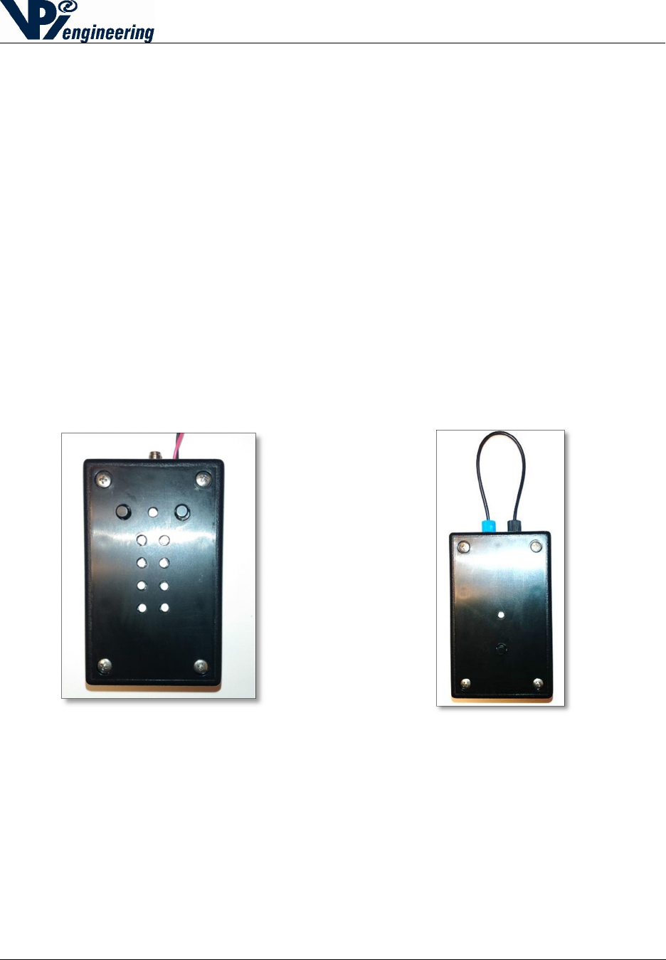
The WOFS system consists of a WOFS Receiver (see Figure 1) in wireless communication with
a WOFS Transmitter (see Figure 2). The Transmitter is connected to a loop of fiber optic cable
that will be wrapped around or through the object to be sealed. Sealed objects can include
equipment racks, panels, doors, or drawers.
If the fiber optic cable is broken, WOFS will trigger an alarm indicating that the seal has been
compromised. The WOFS is also equipped with a security features to resist attempts to “spoof”
the optical signal.
Figure 1 - WOFS Receiver Figure 2 - WOFS Transmitter
2015-07-31
V029627_02_WOFS_Installation_Guide.docx Page 4 of 20
3 Installation of the WOFS Receiver Hardware
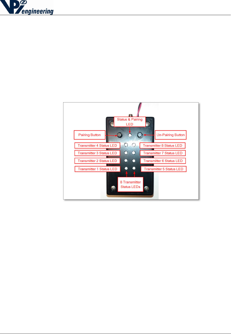
The WOFS Receiver can communicate with up to eight Transmitters (see Figure 3). The
Receiver is typically connected to an alarm panel or to the Integrated Remote Monitoring System
(iRMS).
When the WOFS Receiver is integrated with an iRMS, WOFS supports a user interface at
an operator security station that shows WOFS health, location of alarm, camera video,
and the iRMS can send email and text message notifications.
NOTE: Connecting the WOFS to an alarm panel or to an iRMS will be covered in
Section 5. The functionality of the LEDs and buttons will be covered in Section
14.
Figure 3 - WOFS Receiver
2015-07-31
V029627_02_WOFS_Installation_Guide.docx Page 5 of 20
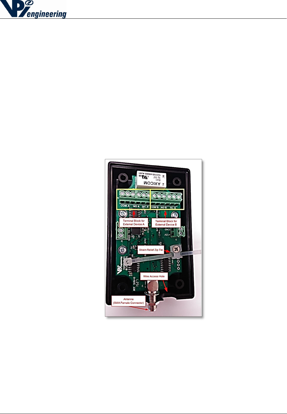
Connecting Power
The Receiver is powered by +12 VDC supplied by the facility where the Receiver is installed.
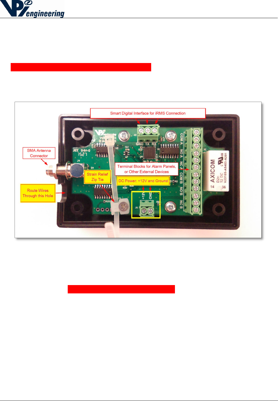
1. Connect power to the terminals by removing the 4 recessed, Phillips-head screws and
open the case to access the terminal blocks.
2. Turn off the source of the facility’s +12VDC.
3. Connect +12 VDC wire and ground wire to Receiver’s DC Power terminals. Run the
wires across the Strain Relief Zip ties, and through the hole next to the SMA antenna
connector (see yellow-highlighted boxes in Figure 4).
Figure 4 - Receiver PC board and terminal blocks
4. Connect the +12VDC wire and ground wire to the facility’s power source, following
NEC guidelines.
NOTE: Do NOT turn on the power source until all of the wiring process is
complete, as instructed later in this manual.
2015-07-31
V029627_02_WOFS_Installation_Guide.docx Page 6 of 20
4 Connecting the Receiver to the iRMS Using the Smart
Digital Interface
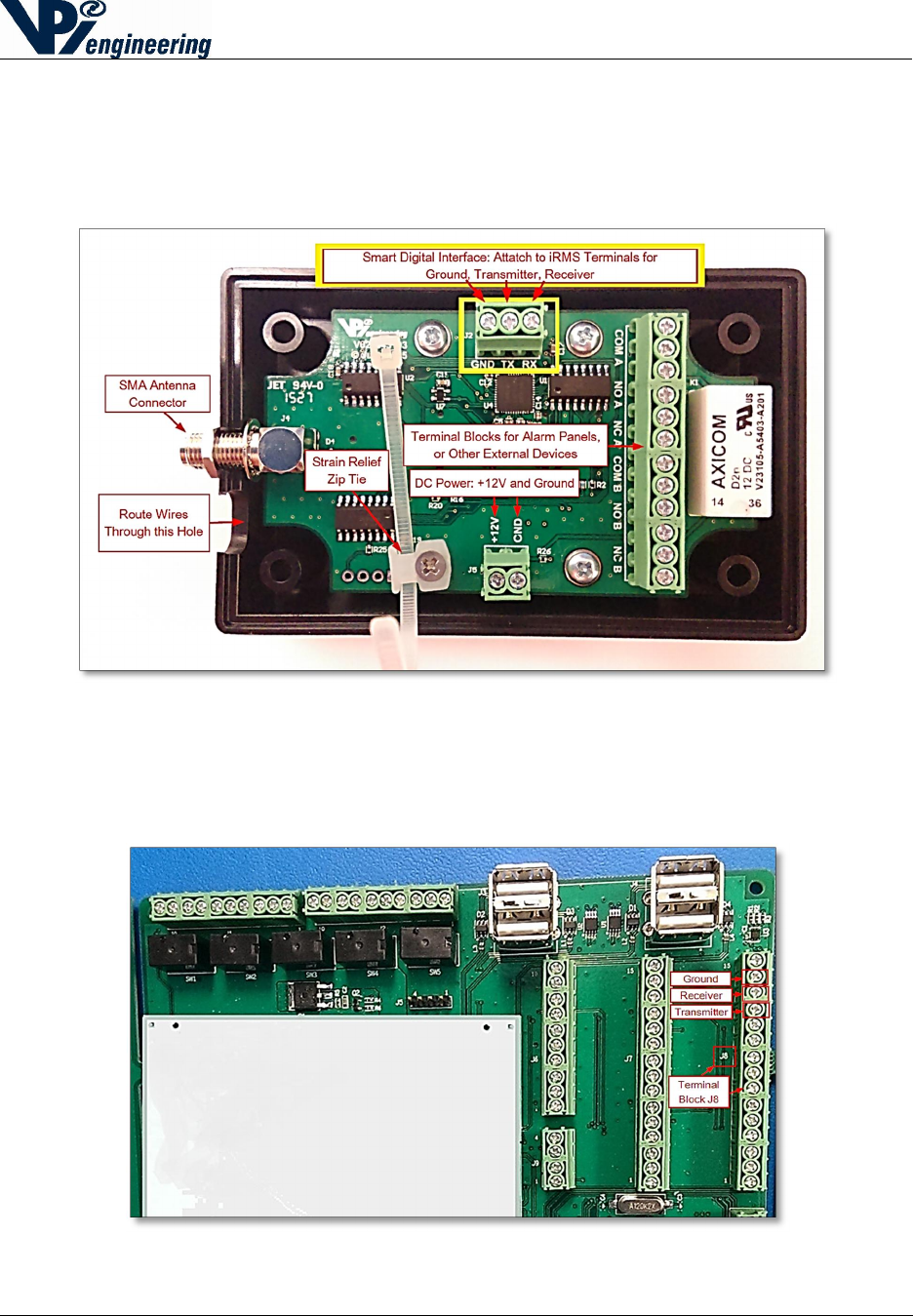
1. On the WOFS Receiver, attach a Ground wire to the Smart Digital Interface (SDI)
Terminal Block to the location labeled GND (see yellow boxes in Figure 5).
Figure 5 - Smart Digital Interface terminal block
2. Open the iRMS unit.
3. Attach the other end of the Ground wire to Terminal Block J8, at location screw #14 (see
Figure 6). For more information, refer to the CHCT manual.
Figure 6 - iRMS terminal Block J8
2015-07-31
V029627_02_WOFS_Installation_Guide.docx Page 7 of 20
4. On the WOFS Receiver, attach the Receiver wire to the Smart Interface Terminal Block
to the location labeled RX (see previous Figure 5).
5. Attach the other end of the Receiver wire to the iRMS Terminal Block J8, at screw #13
(see previous Figure 6).
6. On the WOFS Receiver, attach the Transmitter wire to the Smart Interface Terminal
Block to the location labeled TX (see previous Figure 5).
7. Attach the other end of the Receiver wire to the iRMS Terminal Block J8, at screw #12
(see Figure previous 6).
5 Connecting the Receiver to an Alarm Panel or Other
External Device
The Receiver can also be integrated with an alarm panel or another external device. The
Receiver terminal block has relay terminals for two different devices (device A, and device B),
as shown in Figure 8.
Figure 7 - Receiver's main terminal block, wire access point, zip tie for wires
The PC board labels mean the following:
COM is the common terminal.
NC is the normally closed relay contact (for instances when the relay is not energized).
NO is the normally open relay contact.
To connect external devices to the Receiver:
1. Connect the relay terminal wires inside the WOFS Receiver to the alarm panel (or other
device), following the manufacturer’s directions, using NEC guidelines.

2015-07-31
V029627_02_WOFS_Installation_Guide.docx Page 8 of 20
o Use the terminal jacks that are either Normally Open (N/O) or Normally Closed
(N/C), depending on the configuration of the alarm panel (see section 7 of this
manual for more information on the N/O or N/C requirements).
2. Route the wires from the Receiver terminal block through the hole next to the SMA antenna
connector (see previous Figure 8).
8. Use the zip tie to secure the wires in order to reduce the strain on the terminal block wires
(see previous Figure 8).
9. Reassemble the WOFS Receiver case, and then reattach the Phillips-head screws.
10. Turn on the +12VDC supply to the Receiver.
6 Receiver Antenna
The Receiver has a female SMA connector at the top of the case to connect the 2.4 GHz antenna,
which communicates with the Transmitters. Attach the Receiver Antenna to the Receiver by
placing the antenna carefully on the SMA connector (see previous Figure 8), lining up the center
pin, and turn the antenna clockwise until the antenna is securely attached to the Receiver.
NOTE: The iRMS unit has an antenna external to the iRMS case and can receive transmissions
for the Receiver, or from the Transmitters, using its own iRMS antenna.
2015-07-31
V029627_02_WOFS_Installation_Guide.docx Page 9 of 20
7 Determining if a Device Requires a Normally Open, or
Normally Closed State
Before connecting the Receiver to an alarm panel or other external device, the user must
determine if the alarm system panel (or other device) requires a Normally Open (N/O) or
Normally Closed (N/C) state.
Note: For the rest of this section, it will be assumed that the device being connected is
an alarm panel, but the theory and steps are the same for a different external device.
The external device, such as an alarm panel, when used to connect to the WOFS will dictate
either the use of Normally Closed or Normally Open TID configuration. In some cases, this may
be configurable in the alarm panel.
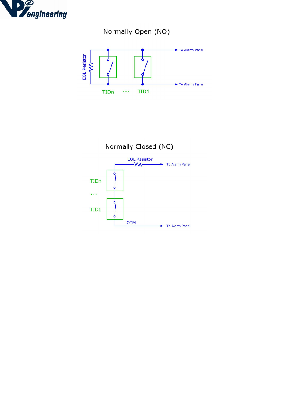
In the N/C case, a high voltage at the alarm panel indicates an alarm (one or more of the
TIDs has opened) or the wiring has been cut. A low voltage at the alarm panel indicates
the wiring has been shorted.
Conversely, in the N/O case, a high voltage indicates a wiring fault (wire has been cut)
and a low voltage indicates an alarm or wire short.
1. In configuring the connection between the WOFS Receivers, and an alarm panel or iRMS,
end-of-line (EOL) resistors are used at the termination of protected loops or “zones” to allow
for differentiation between an active alarm and secure states, in addition to wiring faults or
wire tampering.
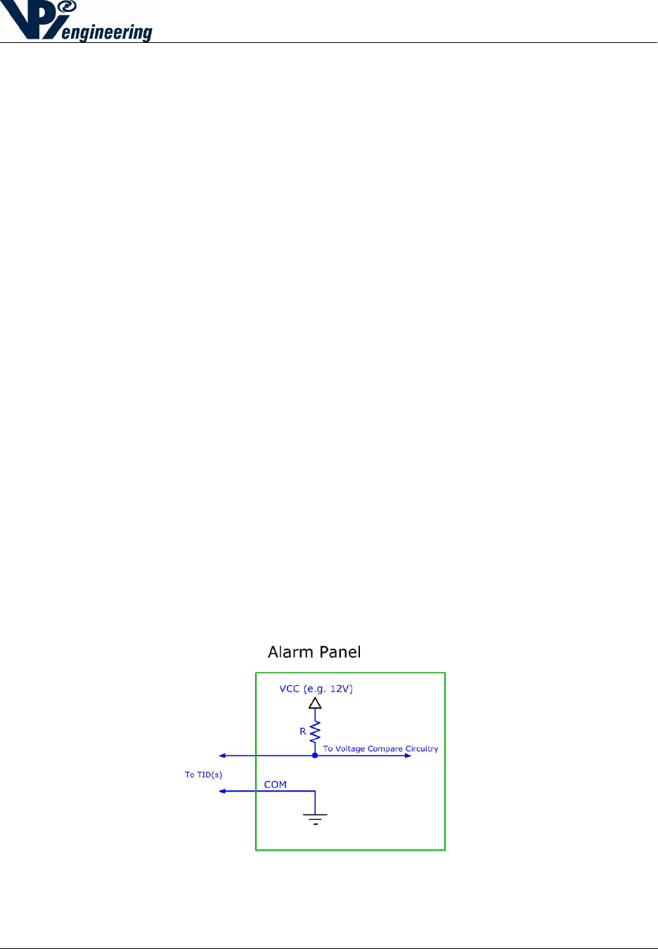
2. As shown in the Figures 9-11, an EOL resistor is used in series with a resistor internal to the
alarm panel to create a voltage divider. Intermediary voltage values indicate a secure (non-
alarming state), high or low voltages indicate an alarm or fault – the actual alarm or fault
state being dictated by whether the Normally Closed (N/C) or Normally Open (N/O)
configuration of the Tamper Indicating Device (TID) is used. The value of the selected EOL
resistor is dependent upon the alarm panel’s specifications.
Figure 8 - Alarm Panel
2015-07-31
V029627_02_WOFS_Installation_Guide.docx Page 10 of 20
Figure 9 - Normally Open configuration
Figure 10 - Normally Closed configuration
2015-07-31
V029627_02_WOFS_Installation_Guide.docx Page 11 of 20
8 Installation of the WOFS Transmitter Hardware
Installation of the WOFS Transmitter Hardware requires three steps:
Installation of the batteries
Mounting the Transmitter to a secured surface
Setting up the Fiber Optic Loop
The WOFS Transmitter is powered by 2 AA-sized batteries. The battery power level is
monitored by the WOFS Receiver.
The Transmitter uses a fiber optic cable to wrap around (or through) the object to be sealed. The
Transmitter is designed to be attached to a flat or cylindrical (minimum 12 inch radius) secured
surface, adjacent to the protected object. In this manner, if an attempt is made to remove the
entire protective enclosure (containing the radioactive material or protected equipment), the
Transmitter will also have to be removed from where it is mounted, and this will send an alarm
to the Receiver.
Tools and Parts Required for Installing the WOFS
Phillips screwdriver
Fiber optic cable: 1mm diameter, with a 2.2mm diameter polyethylene (PE) jacket (e.g.
Industrial Fiber Optics SH4001 Eska series p/n 810004 or equivalent)
o Cable length must be sufficient to secure the protected device, AND allow enough
cable to attach the Transmitter to a nearby, secured surface. Additionally, the
length must include enough cable to allow the cable to be inserted into the cable
terminals at the top of the Transmitter (see Figure 12). The user will provide the
fiber optic cable.
Adhesive mounting tape (included with Transmitter)
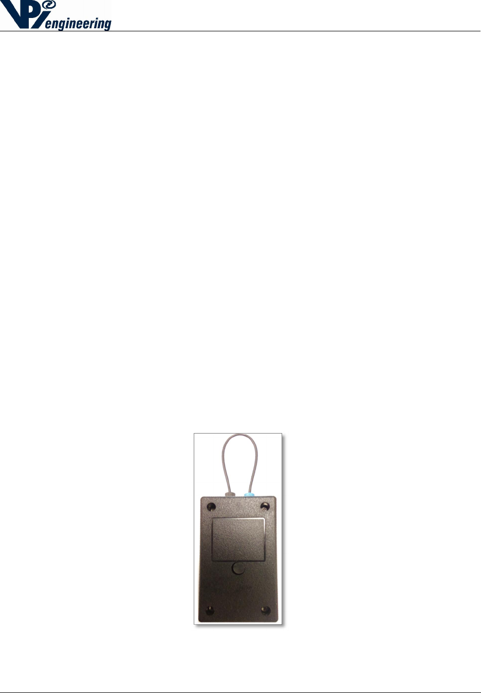
Figure 11 - Transmitter with fiber optic loop (back side)
2015-07-31
V029627_02_WOFS_Installation_Guide.docx Page 12 of 20
9 Installing or Changing Transmitter Batteries
Before mounting the Transmitter to a wall or secured surface, install 2 AA-sized alkaline
batteries using the steps below:
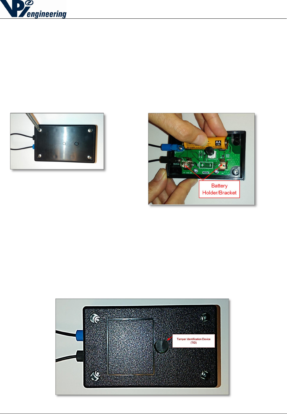
1. Remove the 4 recessed, Phillips-head screws and open the Transmitter case to access the
battery compartment (see Figure 13).
o Remove the old batteries, if applicable.
2. Insert 2 AA-sized alkaline batteries matching the polarity pictured in the battery holder (see
Figure 14).
3. Reassemble the case and reattach the Phillips-head screws.
NOTE: The Transmitter is equipped with a Tamper Identification Device (TID) which will send
an alarm when the Transmitter box is opened or removed from the secured surface (see Figure
15). If the user is changing batteries, the user should notify the Monitor Station(s) that changing
batteries will trigger an alarm.
Figure 14 - Transmitter's Tamper Identification Device (TID)
Figure
13
-
In
serting or removing
batteries: Push the battery into the
battery bracket
Figure
12
-
Removing the four screws to
open the case
2015-07-31
V029627_02_WOFS_Installation_Guide.docx Page 13 of 20
10 Mounting Transmitter on Wall or Secured Surface
Before the WOFS unit is mounted to a secured surface, the user should have determined
how the fiber optic loop is going to be secured around the device to be monitored.
Ensure that the fiber loop surrounding the protected asset can be securely wrapped
around the section necessary to protect, and still reach the WOFS fiber optical
cable terminals.
The Transmitter must be mounted so that the fiber connections to the seal are
inserted and oriented to minimize the strain on the fiber connections.
The Transmitter contains an RF radio and should not be separated from the
Receiver by metal walls or more than 30 ft. Walls or large machinery between
the Transmitter and Receiver will reduce the communication range between the
two devices.
It is recommended to use the included mounting tape, which includes a hole for the TID to
protrude. If using mounting tape included with the WOFS unit, do the following:
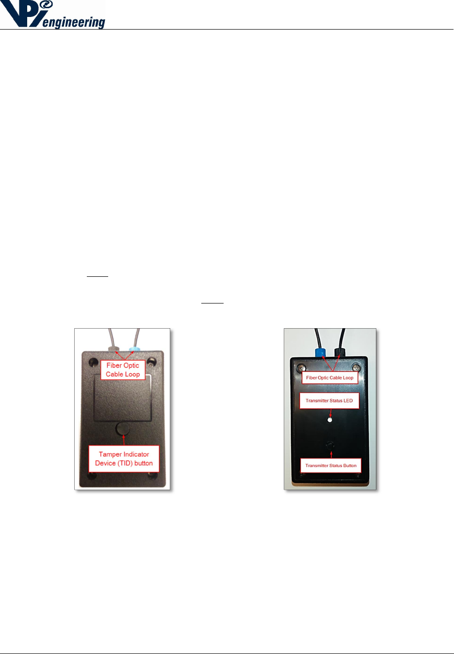
1. Locate the back of the WOFS unit. The back of the unit box has four holes for the
recessed hex nuts, and a Tamper Identification Device (TID) button (See Figure 16). The
back can be differentiated from the front of the Transmitter box, which has Phillips-head
screws, and an LED light (see Figure 17).
Figure 15 - Back of Transmitter with TID button Figure 16 - Front with Status button & Status Led
2015-07-31
V029627_02_WOFS_Installation_Guide.docx Page 14 of 20
2. Peel the paper off one side of the mounting tape.
3. Press the mounting strip onto the back of the Transmitter, making sure to line up the TID
hole on the WOFS unit with the hole in the mounting tape (see Figure 18).
4. Peel the paper from the second side of the mounting tape.
5. Press the WOFS unit onto the pre-determined, secured surface.
11 Setting up the Fiber Loop
The WOFS Transmitter is designed to work with polyethylene-jacketed, 1mm diameter, fiber
optic cable with a 2.2mm diameter jacket, such as Industrial Fiber Optics SH4001 Eska series
(part number 810004 or the equivalent).
The Transmitter has been designed for fiber optic connectors that do not require fiber polishing.
However, if many splices are incorporated in a long fiber loop, polishing will improve optical
transmission and reliability. Polishing may be accomplished using an Industrial Fiber Optics
Polishing Puck (part number 41 0156) along with Polishing Slurry (part number IF 370060).
1. Determine the length of fiber optic loop needed to secure the selected device, AND allow
enough cable to attach the Transmitter to a secured surface. Additionally, provide enough
cable to allow the cable to be inserted into the cable terminals at the top of the
Transmitter.
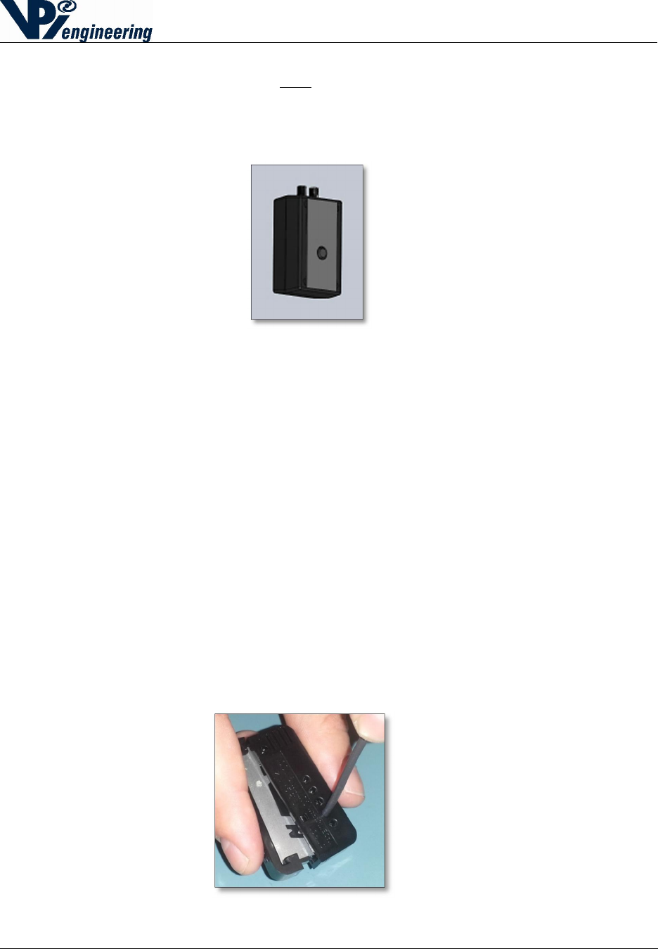
2. Cut the cable using a fiber optic cutter such as the Omron E39-F4 cutter (see Figure 19).
Use Industrial Fiber Optics IF-C-S4 or equivalent splice connectors to splice cable
together, if needed.
Figure
18
-
Fiber optic cutter
(Omron E39-F4)
Figure
17
-
Mounting tape applied to the back of WOFS unit
2015-07-31
V029627_02_WOFS_Installation_Guide.docx Page 15 of 20
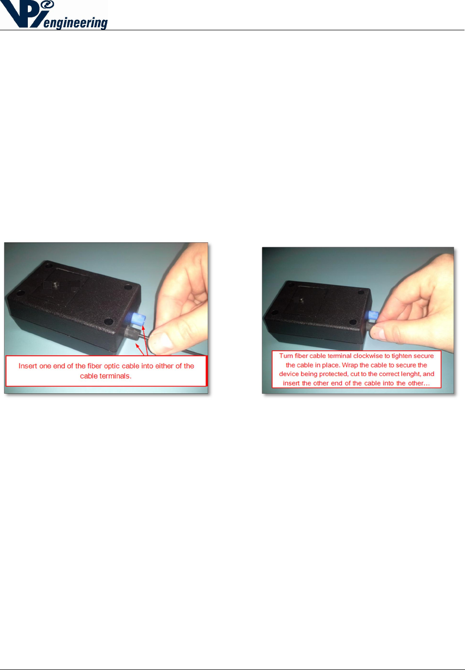
2. Insert one end of the fiber optic cable into the Transmitter screw terminal until fully
seated (see Figure 20).
3. Turn the screw terminal clockwise to secure the cable (see Figure 21). Secure the
protected object (i.e. radioactive material container) with the optic fiber cable, and then
secure other end of the fiber optic loop into the other screw terminal. Either end of the
fiber optic loop can be installed in either screw terminal.
After both ends of the fiber optic loop are connected to the Transmitter, press the Status button
on the Transmitter.
NOTE: If the Transmitter has been paired with a Receiver, and the fiber optic cable is inserted,
the LED light on the Transmitter will turn green for a few seconds. If the Transmitter status light
is red, review the installation process, and make the adjustments needed to correctly install the
fiber optic cable.
Figure 19 - Screwing terminal clockwise to secure cable Figure 20 - Inserting fiber optic cable into terminal

2015-07-31
V029627_02_WOFS_Installation_Guide.docx Page 16 of 20
12 Pairing a WOFS Transmitter to a WOFS Receiver
A Transmitter needs to be paired to a Receiver only once, at the time of installation. The pair will
remain paired thereafter, even after power loss, or during battery replacement. One Receiver can
be paired with (and can monitor) up to 8 Transmitters.
To pair a Transmitter and Receiver:
1. On the Receiver, press and hold the pairing button for 3 seconds. The status LED will start
flashing blue indicating “discovery” mode.
2. On the unpaired Transmitter (be sure the batteries have been installed), press and hold the
Status button for 3 seconds.
o On a previously-paired Transmitter, press and hold the Status button on the
Transmitter for more than 20 seconds, until the status LED rapidly flashes blue, then
continue with step two above.
3. Upon successful pairing, the Transmitter’s status LED and the corresponding Status LED on
the Receiver (number 1, or 2, 3, … through 8) will turn green or red (which indicates
successful pairing and current Transmitter status).
o Repeat this process to pair the next Transmitter.
o When pairing of the Transmitters is complete, press and hold the Receiver’s Pair
button for 3 seconds to take the Receiver out of “discovery” mode.
Caution: If the Transmitter is blinking slowly (1 flash every 2 seconds), the
Transmitter is trying to pair with a different Receiver. The Transmitter must
first be unpaired with its previous Receiver. Follow the process for unpairing
the Transmitter from the first Receiver (see Section 13), and try pairing again
with the second Receiver.
4. It is possible to pair several Transmitters to the Receiver in a more streamline method.
Follow the steps below:
o Hold the Receiver’s Pair button down for at least 3 seconds to enter “discovery”
mode.
o Press and hold the Status button on the Transmitter that will be known as Transmitter
#1. Wait at least 5 seconds for the corresponding status LED to change color.
o Press and hold the Status button on the Transmitter that will be known as Transmitter
#2. Wait at least 5 seconds for the corresponding status LED to change color.
o Press and hold the Status button on the Transmitter that will be known as Transmitter
#3. Wait at least 5 seconds for the corresponding status LED to change color.
o Continue this process until all of the Transmitters are successfully paired. Then, Press
the Receiver’s Pair button for 3 seconds. This will turn off the Receiver’s “discovery”
mode.
o Each paired Transmitter should now have a lit LED on the Receiver, associated with
its Transmitter pair. To check that each have been properly assigned, open and close
the fiber optic loop, and see if the Receiver shows a changing green-to-red-to-green
LED next to the correct number for that transmitter. This will also validate that the
fiber optic loop has been installed correctly.

2015-07-31
V029627_02_WOFS_Installation_Guide.docx Page 17 of 20
13 Unpairing a WOFS Transmitter to a WOFS Receiver
On occasion, the need may arise to unpair a transmitter from its paired receiver. This can be
necessitated when any of the following happens:
A Transmitter may need to be moved to a different location, and paired with a different
Receiver.
A transmitter may not be functioning correctly, and the user may choose to replace one
Transmitter with another.
A Receiver may not be functioning properly, and it will be replaced.
There are several ways to unpair a Transmitter from a Receiver: 1) Use the Receiver to
unpair only one Transmitter, 2) Use the Receiver to unpair all of the Receivers, 3) Use the
Transmitter to unpair from the Receiver. The following instructions explain how to complete
each of these unpairing functions.
1. To unpair ONE Transmitter from a Receiver:
Hold the Receiver’s Unpair button for 15 seconds.
Press the Pair button. At this point, the 1st Transmitter’s Status LED will turn
solid blue.
Release the Unpair button.
Press the Pair button multiple times. This will cause the next Transmitter Status
light to turn solid blue. Continue pressing the Pair button until the desired
Transmitter LED turns solid blue.
Press the Receiver’s Unpair button again for 5 seconds, and the solid blue light
will go out, and the Transmitter is successfully unpaired.
2. To unpair ALL Transmitters from a Receiver:
Hold the Receiver’s Unpair button for at least 30 seconds.
After 30 seconds, the Status LED on the Receiver will flash blue, and then change
to green, and will stay green. All of the other lights on the Receiver will be unlit,
because the Transmitters are no longer paired to the Receiver.
3. To unpair one Transmitter from a Receiver:
Hold down the Transmitter button for more than 20 seconds.
The Status LED on the Transmitter will flash blue rapidly and then will not be lit.
The Transmitter is unpaired from its current Receiver. This can be verified
because Receiver’s Pair Status LED for that particular location will turn red,
because it is looking for a Transmitter.
Caution: Unpairing by using the Transmitter to initiate the process will cause an
alarm, because the Receiver believes the Transmitter has disabled or disturbed.
2015-07-31
V029627_02_WOFS_Installation_Guide.docx Page 18 of 20
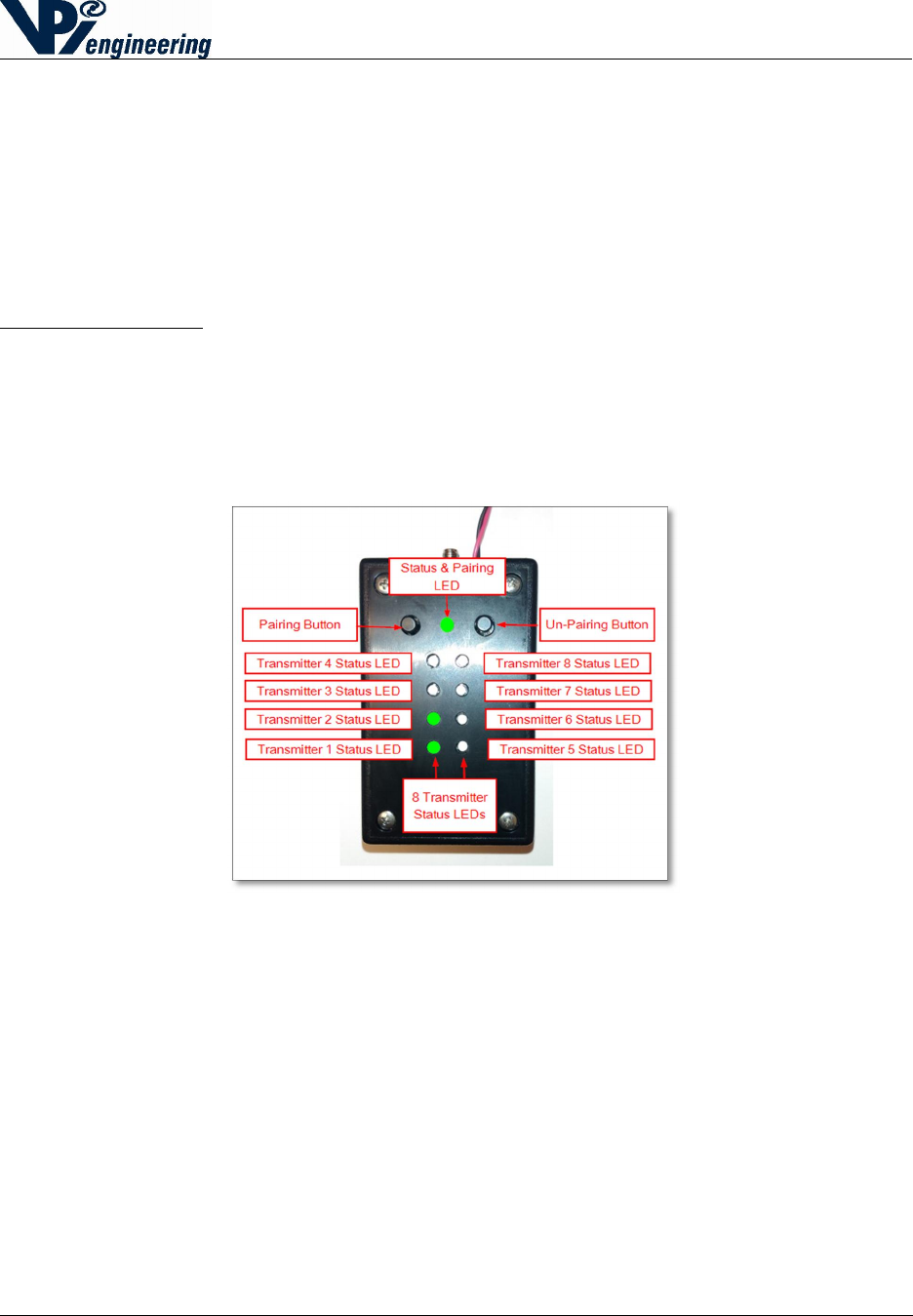
14 Receiver Status Lights
The Receiver’s Status light is on at all times (after correct installation). Any Receiver that has
been paired with a Transmitter will also have its Transmitter Status lights constantly showing for
each paired set.
The Status of a Transmitter paired to the first location on the Receiver is indicated by the LED
labeled 1, the Transmitter paired to the second location is shown by the LED labeled 2, and so
on. LED lights for unused pairs will remain off (see Figure 22).
Receiver Status Light (See Figure 22):
A green light shows the Receiver is functioning correctly.
A red light shows a Transmitter is sending an alarm.
A yellow light shows that a Transmitter is sending an alert, such as a low battery.
A flashing blue light indicates the Receiver is in “discoverable mode” (activated by pressing
the Pairing button).
Figure
21
-
Receiver pair status LEDs and
buttons
2015-07-31
V029627_02_WOFS_Installation_Guide.docx Page 19 of 20
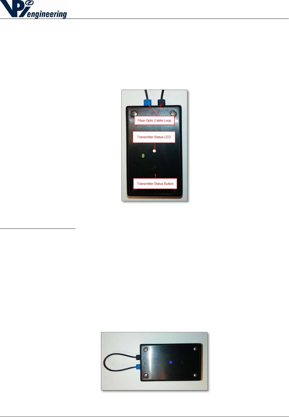
15 Transmitter Status Lights and Checking Transmitter
Status
The Transmitter is designed with a Status Button and an LED light to indicate the Transmitter’s
status (see Figure 23). If the Transmitter has been paired with Receiver (and is within range) the
Status button on the Transmitter can be pressed at any time to check the Transmitter’s status,
lighting up the LED.
Figure 22 - Transmitter Status button and Status LED
Transmitter Status Lights (see Figure 24):
A green light indicates the Transmitter is functioning correctly, and the optic cable is intact.
A red light indicates the Transmitter is sending an alarm (the fiber loop has been
compromised or the tamper indication button has been activated).
A yellow light indicates the Transmitter is sending a low battery alert.
A flashing blue light indicates the Transmitter is searching for a receiver to complete pairing.
There are two different LED states of flashing blue.
o A fast flash (4 flashes per second) shows that the Transmitter is in “open” pairing
mode and can pair to any discoverable Receiver.
o If the LED is blinking slowly (1 flash every two seconds), the Transmitter will only
pair with the Receiver with which it has previously been paired.
Figure 23 - Transmitter Status Lights – in Discovery mode

2015-07-31
V029627_02_WOFS_Installation_Guide.docx Page 20 of 20
16 Regulatory Compliance
FCC Declaration of Conformance
This device complies with part 15 of the FCC rules. Operation is subject to the following two
conditions: (1) This device may not cause harmful interference, and (2) this device must accept
any interference received, including interference that may cause undesired operation. Any
changes or modifications not expressly approved by manufacturer could void the user’s authority
to operate the equipment.
IMPORTANT! Any changes or modifications not expressly approved by the party responsible
for compliance could void the user’s authority to operate this equipment.
FCC Class B Information
NOTE: This equipment has been tested and found to comply with the limits for a Class B digital
device, pursuant to part 15 of the FCC Rules. These limits are designed to provide reasonable
protection against harmful interference in a residential installation. This equipment generates,
uses and can radiate radio frequency energy and, if not installed and used in accordance with the
instructions, may cause harmful interference to radio communications. However, there is no
guarantee that interference will not occur in a particular installation. If this equipment does cause
harmful interference to radio or television reception, which can be determined by turning the
equipment off and on, the user is encouraged to try to correct the interference by one or more of
the following measures:
Reorient or relocate the receiving antenna.
Increase the separation between the equipment and receiver.
Connect the equipment into an outlet on a circuit different from that to which the receiver
is connected.
Consult the dealer or an experienced radio/TV technician for help.
FCC Radiation Exposure Statement
This equipment complies with FCC radiation exposure limits set forth for an uncontrolled
environment. This equipment should be installed and operated with minimum distance 20cm
between the radiator and your body.
CE Conformity
This equipment complies with the essential requirements and other relevant provisions of
Directive 2006/95/EC.