Visiplex VNS22XX Wireless Paging Controller User Manual VNS2210 Manual
Visiplex, Inc. Wireless Paging Controller VNS2210 Manual
Visiplex >
Contents
- 1. VNS2200 Manual
- 2. VNS2210 Manual
- 3. WPRP-1 Manual
VNS2210 Manual

VNS2210 Amplifier & Controller Installation Guide – Version 2.00
VNS2210 Amplifier & Controller Installation Guide
VNS2210 Amplifier & Controller Installation
1. Determine the installation location for the VNS2210 device. Consider the following when determining the installation location:
Standard VNS2210 device is equipped with AC to DC power adaptor and requires a standard 110VAC or 220VAC power
outlet. The power adaptor consists of 6’ DC power cable and 6’ of AC power cord. Consider these cable lengths and the
distance between the power outlet and the VNS2210 device.
For VNS2210 devices equipped with VNS2256 option: The solar panel is equipped with 15’ feet of power cable. Consider
this cable length and the distance between the outdoor solar panel installation location and the VNS2210 device.
For VNS2210 devices equipped with VNS2267, VNS2268, VNS2261 or VNS2263 option: The intercom wall station is
equipped with 25’ feet of data cable. Consider this cable length and the distance between the intercom wall station
installation location and the VNS2210 device.
For VNS2210 devices equipped with VNS2264 option: The ambient noise level sensor is equipped with 10’ feet of data
cable. Consider this cable length and the distance between the ambient noise level sensor installation location and the
VNS2210 device.
2. Position the VNS2210 device on the mounting surface and confirm that it is vertical to the floor.
Note: When the device is installed properly, the LED should be on the left top corner (front view).
3. Secure the VNS2210 device to the wall using screws appropriate for the mounting surface (use 1.5”-2” long screws).
4. If an external antenna (2.5db or 3db gain) is used, install it on the BNC connector.
5. Connect the output devices to their respective port. Below are the available connector types that are installed on your device:
Strobe Lights: Strobe Light or 12VDC Controlled Device (for VNS2282 option, STROBE 1 and STROBE 2 ports)
Speakers: Speaker Audio Output (for VNS2281 option, SPEAKER 1 and SPEAKER 2 ports)
Intercom: Intercom Wall Station or Ambient Noise Level Control (for VNS2267, VNS2268, VNS2261, VNS2263 & VNS2264
options, INTERCOM port)
Audio: Line Level Audio Output with Dry-Contact Closure (for VNS2284 option, AUDIO and RELAY ports)
Relay: Dry-Contact Closure (for VNS2285 option, RELAY ports)
6. Connect the other end of each cable to the appropriate output device and verify proper connections.
7. Connect the power adaptor male connector to the POWER port of the VNS2210 device.
Note: The VNS2210 devices should be protected from direct rain and snow, and if possible, from direct sun. Outdoor installation
should include an overhang to protect the VNS2210 device from direct rain, snow and sun.
VNS2267 & VNS2268 - Two Way Intercom Option
1. Before installation, consider the distance between the VNS2210 device and the VNS2267 or VNS2268 intercom wall station. The
VNS2210 device and the intercom wall station will be connected using the provided CAT5 cable (25’ long).
2. Follow steps 1-7 of the VNS2210 Amplifier & Controller Installation described above.
3. Disconnect the power source connector from the POWER port of the VNS2210 device.
4. Run the data cable between the VNS2210 device and the intercom wall station.
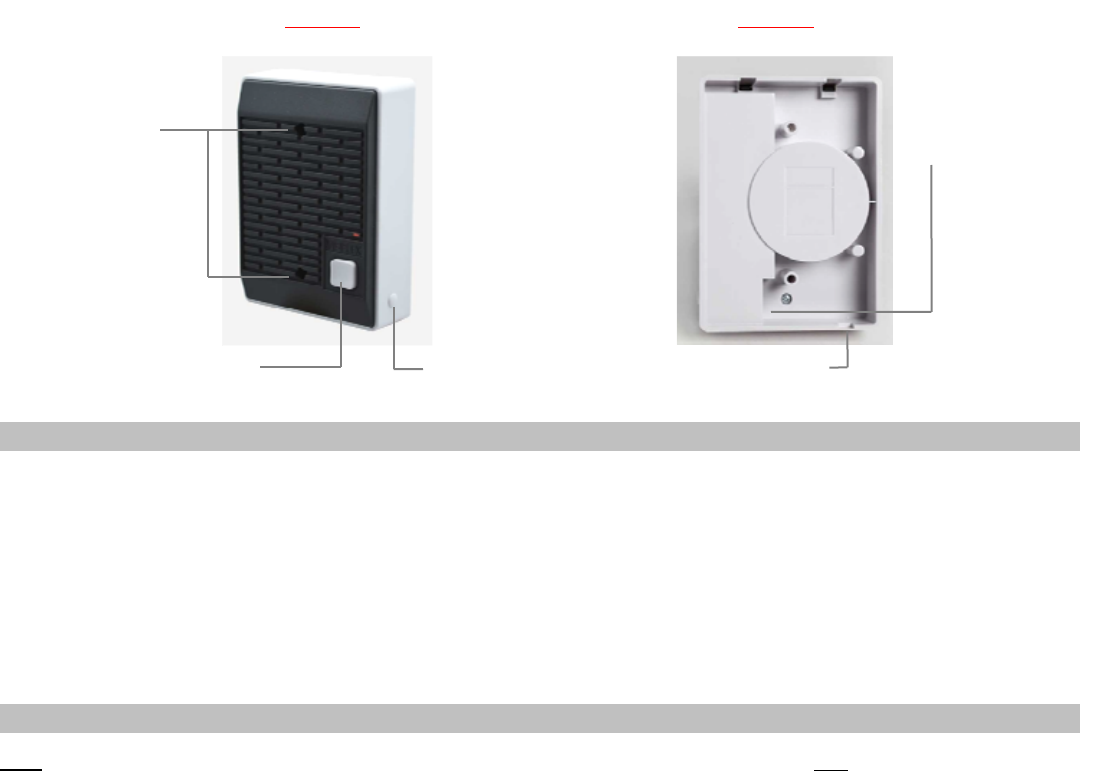
5. Connect the RJ45 data cable to the intercom wall station (Image 3).
6. Attach the intercom wall station to a single gang box using supplied 2 machine screws. For surface installation, use the
metal/wood screws (Image 2).
Note: When mounting directly to wall surface (without gang box), remove the breakable data cable outlet (Image 3) and pass
the cable through the opening at the bottom.
7. Connect the other end of the cable (RJ45 connector) to the INTERCOM port on the VNS2210.
8. Connect the power source connector to the POWER port of the VNS2210 device.
9. Document the location and the serial number of the main VNS2210 device.
Note: The serial number of the VNS2210 device is required for system programming.
10. To test communication with the base station, push the CALL button on the wall station.
VNS2210 Amplifier & Controller Installation Guide – Version 2.00
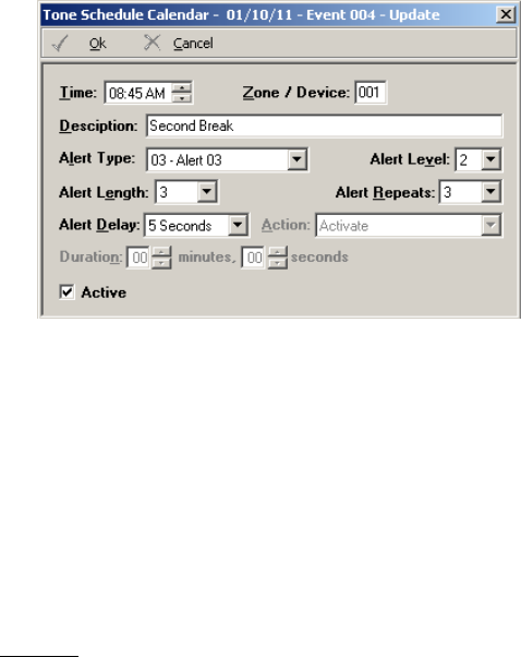
Mounting Holes
Call Button Microphone Sensitivity
Adjustment Breakable Data Cable Outlet
RJ45 Data Cable Connection
Default Pre-Programmed Tones & Alerts
1. Single Tone
2. Dual Siren
3. Voice Message: “Attention! This is a lockdown emergency. Please take refuge immediately. This is not a drill”
4. Voice Message: “Attention! This is an evacuation emergency. Please evacuate the building and follow evacuation procedures”
5. Voice Message: “Attention! The emergency condition has been cleared. Resume to normal condition”
6. Voice Message: “Attention! This is a lockdown drill. Please take refuge in the nearest building and follow lockdown procedures.
This is only a drill”
7. Beep Alert
8. School Bell
9. Long Tone
Programming Custom Audio Messages using VPS or VisiDB Software
Note: The VisiDB software utility is compatible only with older versions of the VNS2210. Use VisiDB only with VNS2210 with versions
earlier than 4.00 and VNS2200 with versions earlier than 3.18.
1. Connect your VNS2210 receiver module to the PC using the special programming power supply. This power supply will have a
serial cable attached to the VNS2210 power port.
2. Make sure a microphone is connected to your PC.
3. Record your WAVE files using a sound recorder software utility or Windows Sound Recorder (located under Start
Menu\Programs\Accessories\Entertainment on Windows XP) or any other audio editing software.
4. Prepare your WAVE files for upload and make sure that they are saved at the correct format:
4.1 Record a wave file or open a pre-recorded file (File, Open).
4.2 Go to File, Save As.
4.3 Enter a file name for the recorded or modified file.
4.4 Click on Change button.
4.5 Set Format to PCM.
4.6 Set Attribute to one of the following: 8.000 kHz, 8 bit, Mono or 11.025 kHz, 8 bit, Mono (Note: Versions 3.05 and
higher may also support 22.050 kHz, 8 bit, Mono).
4.7 Click Save.
4.8 Repeat for all additional WAVE files.
5. Run the VPS or VisiDB software.
6. For VisiDB:
6.1 VisiDB will be connected to the receiver module once it is open. Connected to PA Speaker should be displayed in the
lower right hand corner of the screen.
6.2 Click on Devices menu, Device Programmer, Custom Alerts Programmer. The programmer screen will be
displayed.
7. For VPS (note: VPS software does not support all versions and models):
7.1 VPS will be connected to the receiver module once it is open. Connected to VNS2210 should be displayed in the lower
right hand corner of the screen.
7.2 Click on Wireless Devices menu, VNS2200/VNS2210 Programmer, Alerts. The programmer screen will be
displayed
Ima
g
e 2 Ima
g
e 3
VNS2210 Amplifier & Controller Installation Guide – Version 2.00
8. Click on the Read Configuration button. This will tell you how many alerts the receiver module is set to hold.
9. Click on the Expanded Memory Alerts Configuration drop down menu and select how many alerts the receiver module needs
to hold.
Note: The more alerts a receiver module needs to hold, the shorter the alert needs to be.
10. Click Update Configuration to change the amount of alerts the receiver module will hold.
Note: Updating the memory configuration will erase all existing custom alerts previously programmed.
11. Enable the alert numbers that will hold a file by checking the box to the left.
12. Click on the Browse button and search for your WAV file.
13. Click on your file then click on the Open button to the right.
14. Your WAV file should now be in the File Name box. Repeat Steps 12 and 13 for as many files as necessary.
15. Click the Program button at the top of the programmer to upload your WAV files to your receiver module.
16. Disconnect the VNS2210 receiver.
If required, connect additional VNS2210 receivers and program as described above.
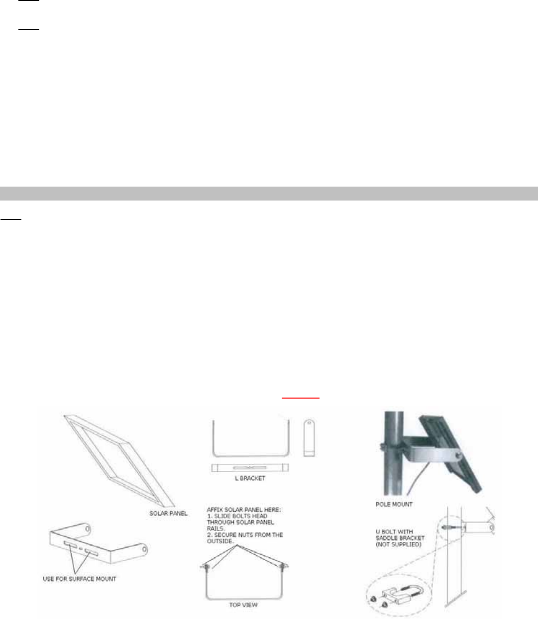
VNS2256 - Solar Charger with Internal Battery - Option
Note: The instructions below are for general reference only. Always review the instructions enclosed with the solar panel before
installation.
1. Follow steps 1-6 of the VNS2210 Amplifier & Controller Installation described above.
2. Secure the mounting bracket to a permanent structure facing the southern sky. Use screws or bolts appropriate for the
mounting surface.
3. Secure the solar panel to the mounting bracket (Image 3).
4. Adjust the solar panel to an angle between 45 and 60 degree from the horizon.
5. Tighten all screws to lock mounting bracket and solar panel in position.
6. Connect the solar panel male connector to the POWER port of the VNS2210 device.
7. Allow 24 hours for battery to recharge.
Ima
g
e 3
VNS2210 Amplifier & Controller Installation Guide – Version 2.00
VS2511 - Weekly Tone & Bell Schedule Option
The weekly tone and bell schedule allows the VNS2210 to activate tones, bells or audible alerts stored in its memory according to a
pre-programmed weekly schedule. The weekly schedule consists of 48 daily events that can activate a respective tone, bell or
audible alert on the wireless receiver. The VNS2210 stores up to four different weekly schedules in its memory with one active
schedule.
Follow these steps to program a weekly schedule (see IMPORTANT NOTES at the end of this section):
1. Download and install the VPS software and USB driver. Make sure the VNS2210 is powered on and connected to the USB port on
the PC.
2. Click on Wireless Devices, VNS2200/VNS2210 Programmer.
3. Click on Read to retrieve the VNS2210 setting. Then, click on Schedule, Weekly Tone & Bell Schedule.
4. The Weekly Tone & Bell Schedule dialog box will be displayed. The last schedule file edited by the user will be retrieved from
the disk and displayed. If this file does not exist, a new file will be created by the VPS software. Below are the fields and functions
description:
Close Close the Weekly Tone & Bell Schedule dialog box.
Edit Display a dialog box that allows updating the highlighted event on the schedule list (see step
5).
Upload Upload the displayed schedule file in to the VNS2210 memory. This command will overwrite
the existing programming of the selected schedule.
Download Download the active schedule from the VNS2210 memory to the PC.
Open Open and display a previously saved schedule file.
Note: The schedule is not active until uploaded to the VNS2210. Use the Upload command to
program this schedule in to the VNS2210.
Save As Save the displayed schedule to a file on the PC for later use.
Displayed Week Day Display the scheduled events for the selected day of the week.
Copy From Copy the daily events of the Displayed Week Day to the selected Week Day (see step 6).
Test Tone Test the tone or function programmed in to the highlighted event on the list.
Slot Set and display the active weekly schedule.
Last Date & Time
Read from Device Last date and time information read from the VNS2210 when the dialog was opened.
Set Date & Time Now Synchronizes the VNS2210 clock to the PC date and time.
File Name Name of schedule file displayed.
Work Offline Allows performing modifications to the schedule file without programming the VNS2210
(usually followed by the Upload command).
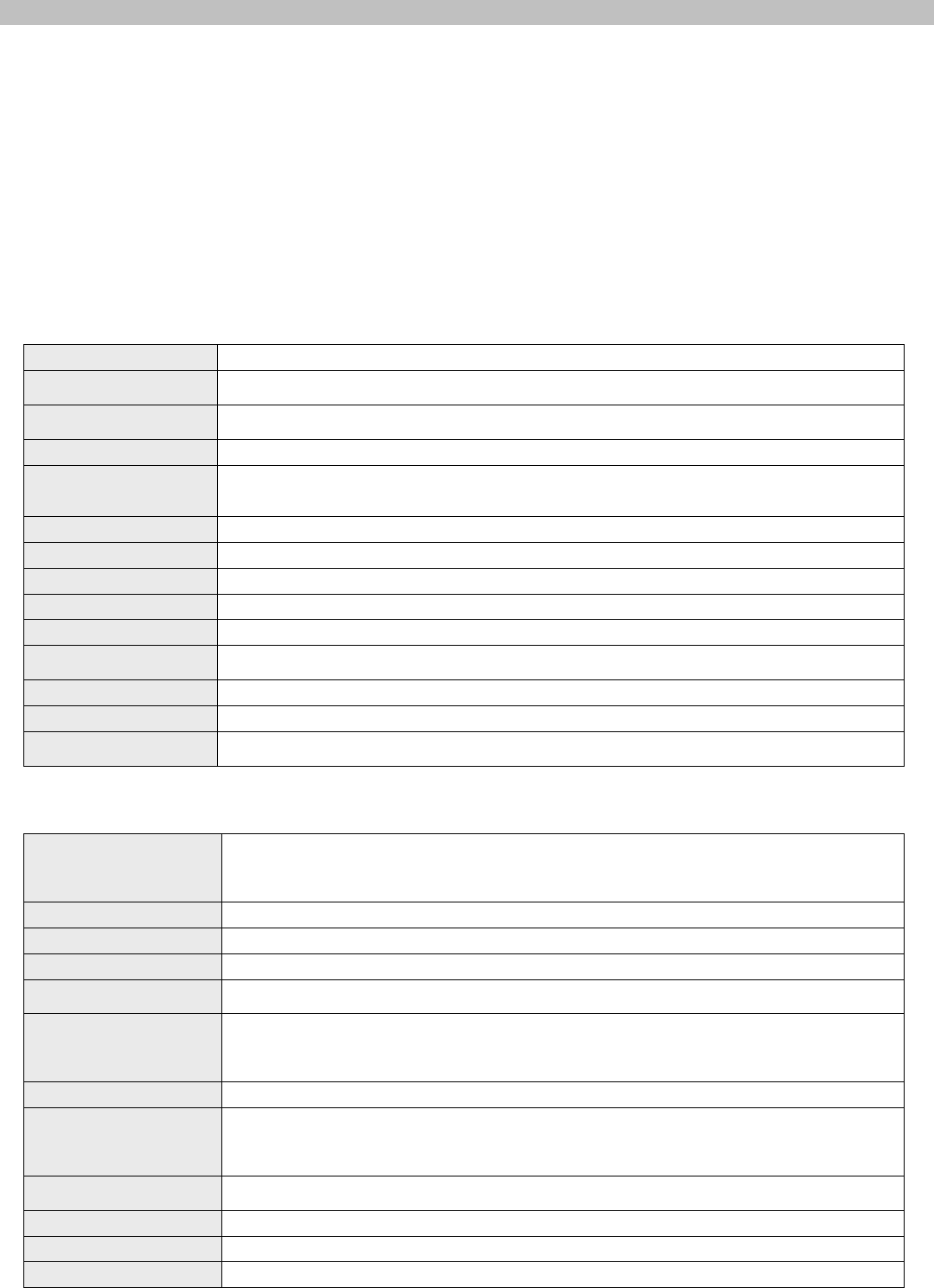
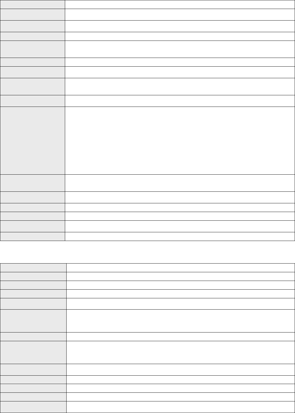
5. If the Edit command is selected, the Weekly Tone & Bell Schedule – Edit dialog box will be displayed. Below are the fields and
functions description:
Save
Update the schedule file and VNS2210 (when Work Offline box is cleared) with changes.
Note: If the Work Offline check box is checked, changes made to the schedule programming
are only saved to the disk and are not written in to the VNS2210 memory. To program the
VNS2210, click on Upload when all changes have been applied.
Cancel Ignore all changes and exit.
Time Time of day when then tone should be generated or an event should be activated.
Zone / Device ID Not applicable to VNS2210. Enter 001.
Description General description for the event.
Note: This field is saved on the PC database only and is not programmed in to the VNS2210.
Alert Type
Type of tone or alert that will be activated by the VNS2210.
Alert 11 and up will activate a customized user-programmed audio alert stored in the
VNS2210.
Note: Alert Type with number higher than 90 are reserved for special operations.
Alert Level Volume of tone played.
Alert Length
Length of tone (in some cases, created by repeating a shorter tone). In some cases, can also
used to determine the length of dry-contact closure or opening.
Note: Alert length 9 (if supported) will send the selected Alert Type three times with a one
second pause between each repeat.
Alert Repeats Number of times to repeat the selected tone sequence (as determined by Type, Level and
Length).
Alert Delay Delay between each repeat of the tone sequence.
Action Determines the type of activation command for alerts 10 and 91-99.
Duration Determines time interval for alerts 9-10 and 91-99.
VNS2210 Amplifier & Controller Installation Guide – Version 2.00
Active Determine if an event is active. Non active events are stored but not executed.
Note: An active events must be assigned with Zone / Device ID larger than 0.
6. If the Copy From command is selected, the schedule will be copied from the selected displayed day to the selected Week Day.
IMPORTANT NOTES
1. When the Weekly Tone & Bell Schedule programming screen is opened, it displays the last file that was edited by the user.
The displayed schedule may be different than the actual schedule data stored in to the VNS2210 (unless the VNS2210 was
previously programmed with that schedule).
2. To ensure the schedule displayed is same as the schedule programmed in to the VNS2210, press Download after opening the
Weekly Tone & Bell Schedule programming screen. This will download and display the active schedule from VNS2210. The
schedule is downloaded and saved by default to the Default.tws file. Use the Save As to save the schedule under a different
name.
3. All changes made are applied to the current active slot that represents the current active weekly schedule. Make sure you select
the correct slot before using the Edit, Download and Upload commands.
4. Every time the Slot is changed, the appropriate schedule is downloaded from the VNS2210 and displayed.
5. Unless the Work Offline check box is cleared, changes made to the schedule DO NOT update the schedule stored in the VNS2210
until the Upload command is used. Always upload the schedule to the VNS2210 after schedule changes are completed.
6. Use the Upload command to program a schedule that was loaded using the Open command.
7. It is recommended that each schedule used will be downloaded from the VNS2210 and saved to the disk with a name that will
describe it appropriately. If required, saved schedules can be loaded to the VPS using the Open command and then programmed
in to the VNS2210 using the Upload command.
8. The execution of the schedule programmed in to the VNS2210 is dependent on the date and time stored in its internal clock. This
internal clock has to be kept accurate by receiving time updates from a PC connected to it via the USB port.
VS2511 - Calendar Tone & Bell Schedule Option
The calendar tone & bell schedule allows the VNS2210 to activate tones, bells or audible alerts stored in its the according to a pre-
programmed annual schedule. The schedule calendar consists of 42 daily events that can activate a respective tone, bell or audible
alert on the VNS2210. Days with active events are marked with an Orange indicators to the left of the date on the calendar.
Unlike the weekly schedule, events have be programmed for each day of the calendar year and there is only one active schedule.
When required, events can be copied from one period to other periods for easy programming.
Follow these steps to program a schedule calendar (see IMPORTANT NOTES at the end of this section):
1. Download and install the VPS software and USB driver. Make sure the VNS2210 is powered on and connected to the USB port on
the PC.
2. Click on Wireless Devices, VNS2200/VNS2210 Programmer.
3. Click on Read to retrieve the VNS2210 setting. Then, click on Schedule, Calendar Tone & Bell Schedule.
4. The Calendar Tone & Bell Schedule dialog box will be displayed. The last schedule file edited by the user will be retrieved from
the disk and displayed. If this file does not exist, a new file will be created by the VPS software.
5. If you prefer to have a schedule that starts with a month other than January, use the Rotate command to change the first month
of the schedule before creating any daily events. Select Rotate 1 Month Forward on the Schedule Rotation drop down list and
click on Rotate until the desired first month is displayed.
VNS2210 Amplifier & Controller Installation Guide – Version 2.00
Below are the fields and functions description:
Close Close the Calendar Tone & Bell Schedule dialog box.
Edit Display a dialog box that allows updating the highlighted event on the schedule list (see step
6).
Upload Upload the displayed schedule file in to the VNS2210 memory. This command will overwrite
the existing programming of the schedule.
Download Download the schedule from the VNS2210 memory to the PC.
Open Open and display previously saved schedule file.
Note: The schedule is not active until uploaded to the VNS2210. Use the Upload command to
program this schedule in to the VNS2210.
Save As Save the displayed schedule to a file on the PC for later use.
Apply as Default Week Copy the events programmed in to the days indicated by the Selected Week field to all other
weeks of the year.
Selected Period Indicate the range of dates of the currently selected calendar days. This range can also be
selected by clicking on the first day of a period, holding the Shift key, and clicking on the last
day of a period.
Copy Copy the events of the days in the Selected Period to the period starting at the Copy to
Period Starting at date.
Schedule Rotation
Rotate the schedule forward or backwards by a day or a month. Use the Rotate command to
apply the required changes.
When the schedule is rotated by one day forward, all events are moved forward by one day
and the events of the last day of the year are copied to the first day of the year.
When the schedule is rotated by one month forward, the first month of the calendar is
removed and a new month is added at the end of the calendar. The events of the removed
month are copied to the added month at the end of the calendar.
When the schedule is rotated by one day backwards, all events are moved backwards by one
day and the events of the first day of the year are copied to the last day of the year.
When the schedule is rotated by one month backwards, the last month of the calendar is
removed and a new month is added at the beginning of the calendar. The events of the
removed month are copied to the added month at the beginning of the calendar.
Apply Allow activation or deactivation of events on a selected day or month as indicated by the
Events drop down list.
Note: Only events with Zone / Device ID larger than 0 can be activated.
Active Events Count
for Display the number of active events on the selected day.
Test Tone Test the tone or function programmed in to the highlighted event on the list.
File Name Name of schedule file displayed.
Last Date & Time
Read from Device Last date and time information read from the supported system when this dialog was opened.
Set Date & Time Now Synchronizes the VNS2210 clock to the PC date and time.
6. If the Edit command is selected, the Calendar Tone & Bell Schedule – Edit dialog box will be displayed. Below are the fields
and functions description:
Save Update the schedule file with changes.
Cancel Ignore all changes and exit.
Time Time of day when then tone should be generated or an event should be activated.
Zone / Device ID Not applicable to VNS2210. Enter 001.
Description General description for the updated event.
Note: This field is saved on the PC database only and is not programmed in to the VNS2210.
Alert Type
Type of tone or alert that will be activated by the VNS2210.
Alert 11 and up will activate a customized user-programmed audio alert stored in the
VNS2210.
Note: Alert Type with number higher than 90 are reserved for special operations.
Alert Level Volume of tone played.
Alert Length
Length of tone (in some cases, created by repeating a shorter tone). In some cases, can also
used to determine the length of dry-contact closure or opening.
Note: Alert length 9 (if supported) will send the selected Alert Type three times with a one
second pause between each repeat.
Alert Repeats Number of times to repeat the selected tone sequence (as determined by Type, Level and
Length).
Alert Delay Delay between each repeat of the tone sequence.
Action Determines the type of activation command for alerts 91-99.
Duration Determines time interval for alerts 91-99.
Active Determine if an event is active. Non active events are stored but not executed.
Note: An active events must be assigned with Zone / Device ID larger than 0.
VNS2210 Amplifier & Controller Installation Guide – Version 2.00
7. If the Copy command is selected, the schedule will be copied from the Selected Period to the period starting at the date
indicated by the Copy to Period Starting at field.
8. If the Rotate command is selected, the schedule will be rotated by one day or one month forward or backwards.
IMPORTANT NOTES
1. When the Calendar Tone & Bell Schedule programming screen is opened, it displays the last file that was edited by the user.
The displayed schedule may be different than the actual schedule data stored in to the VNS2210 (unless the VNS2210 was
previously programmed with that schedule).
2. To ensure the schedule displayed is same as the schedule programmed in to the VNS2210, press Download after opening the
Calendar Tone & Bell Schedule programming screen. This will download and display the schedule from VNS2210. The schedule
is downloaded and saved to the Default.tgc file. Use the Save As to save the schedule under a different name.
3. Changes made to the schedule DO NOT update the schedule stored in the VNS2210 until the Upload command is used. Always
upload the schedule to the VNS2210 after schedule changes are completed.
4. The execution of the schedule programmed in to the VNS2210 is dependent on the date and time stored in its internal clock. This
internal clock has to be kept accurate by receiving time updates from a PC connected to it via the USB port.
VNS2210 Amplifier & Controller Installation Guide – Version 2.00
VNS2210 Amplifier & Controller – Connections and Adjustments
Port Pin Out (Front View, Left to Right)
POWER
Controlled Device
(12VDC) Output Speaker Audio
Output AUDIO RELAY
1 (Center Pin) – VDC (IN) – Strobe 1, GND (GRN) Speaker 1, Wire 1 Audio GND (GRN)
2 – GND + Strobe 1, 12V (PUR) Speaker 1, Wire 2 GND Output (PUR)
– Strobe 2, GND (GRN) Speaker 2, Wire 1
+ Strobe 2, 12V (PUR) Speaker 2, Wire 2
Notice to User Regarding Radio Frequency Interference
Thisdevicecomplieswithpart15oftheFCCRules.Operationissubjecttothefollowingtwoconditions:(1)Thisdevicemay not
causeharmfulinterference,and(2)thisdevicemustacceptanyinterferencereceived,includinginterferencethatmaycause
undesiredoperation.
Changesormodificationsnotexpresslyapprovedbythepartyresponsibleforcompliancecouldvoidtheuser'sauthorityto
operatetheequipment.
NOTE:ThisequipmenthasbeentestedandfoundtocomplywiththelimitsforaClassBdigitaldevicepursuanttoPart15ofthe
FCCRules.Theselimitsaredesignedtoprovidereasonableprotectionagainstharmfulinterferenceinaresidentialinstallation.
Thisequipmentgenerates,uses,andcanradiateradiofrequencyenergyand,ifnotinstalledandusedinaccordancewiththe
instructions,maycauseharmfulinterferencetoradiocommunications.However,thereisnoguaranteethatinterferencewillnot
occurinaparticularinstallation.Ifthisequipmentdoescauseharmfulinterferencetoradioortelevisionreception,whichcanbe
determinedbyturningtheequipmentoffandon,theuserisencouragedtotryandcorrecttheinterferencebyoneormoreofthe
followingmeasures:
‐Reorientorrelocatethereceivingantenna.
‐Increasetheseparationbetweentheequipmentandthereceiver.
‐Connecttheequipmentintoanoutletonacircuitdifferentfromthattowhichthereceiverisconnected.
‐Consultthedealeroranexperiencedradio/TVtechnicianforhelp.
RFRadiationHazardWarning(productswithactivatedtransmitoptiononly):ToensurecompliancewithFCCRFexposure
requirements,thisproductshouldbepositionednolessthan30cmfromyourbodyornearbypersonsduringcontinuoususe.
POWER (DC Jack)
2-Way Intercom or Ambient
Noise Level Control (Optional)
Transmit Antenna (optional)
Receive Antenna (optional)
Status LED
SPEAKER 1 and SPEAKER (Optional)
STROBE 1 and STROBE 2 (Optional)
(
Green: -
,
Pur
p
le: +
)
Manual Volume Adjustment
USB (Programming)
RELAY (Optional)
AUDIO (Optional)