Visonic FLD550PG2 Flood detector User Manual User manual 23018
Visonic Ltd. Flood detector User manual 23018
Visonic >
manual
D-303731 FLD-550 PG2 Installation Instructions 1
FLD-550 PG2
PowerG Wireless Flood Detector
Installation Instructions
1. INTRODUCTION
The FLD-550 PG2 is a fully supervised two-way indoor, PowerG flood detector, used to detect the presence of water based fluids at
any desired location. The FLD-550 PG2 sends the parameters of the specific alarm to the control panel using PowerG two-way
communications protocol.
The FLD-550 PG2 tamper switch is activated when the cover is removed.
A periodic supervision message is transmitted automatically. The control panel is thus informed, at regular intervals, of the unit’s active
participation in the system.
An LED lights whenever alarm or tamper events are reported. The LED does not light while a supervision message is being transmitted.
Operating power is obtained from an on-board 3 V Lithium battery. When the battery voltage is low, a “low battery” message is sent to the
receiver.
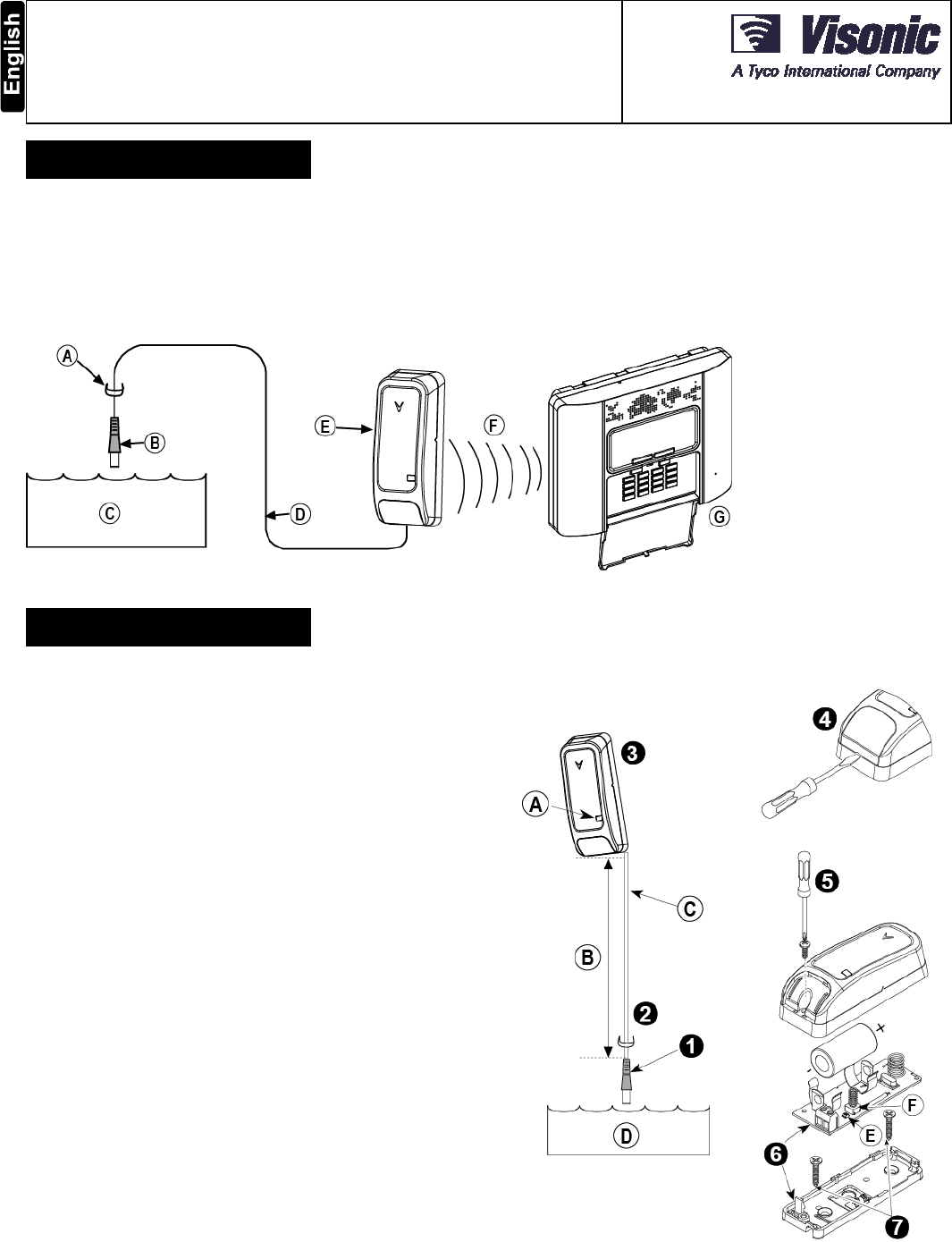
A. Clamp (1 of 3) – attach
slightly above flood
detector
B. Flood sensor
C. Water
D. Flood sensor cable
E. FLD-550 PG2
F. PowerG code alarm
G. Alarm system
Figure 1. Using the FLD-550 PG2
2. INSTALLATION
2.1 Mounting
1. Attach the flood sensor near the floor.
2. Secure the flood sensor and its cable to the wall using the three
wire clamps. One clamp should be fastened immediately above
the flood sensor. The flood sensor should be installed only in a
vertical position, and facing downward. The remaining two
clamps can be used as required (see Figures 1 and 2).
Note: To provide better protection against rats, it is
recommended that the flood sensor cable be placed inside a
metal/plastic pipe.
3. Attach the flood detector to the wall. The flood detector should
be placed as high up as possible on the wall to improve
communication and to prevent the flood detector itself from
coming into contact with water in the event of flooding.
4. Insert a flat-edged screwdriver into the slot and push upward to
remove cover.
5. Remove the screw and separate the cover from the base.
6. Remove the PCB board.
7. Mark and drill 2 holes in the mounting surface and fasten the
base with 2 countersunk screws.
Risk of explosion if battery is replaced by an incorrect type. Dispose
of used battery according to manufacturer's instructions.
Note: 868 MHz device is illustrated in the above example. The
same mounting procedure should be performed for 433 MHz and
915 MHz devices.
A. Transmission LED
B. 2 -3 m (recommended length)
C. Flood Sensor Cable
D. Water
E. Enroll button
F. Tamper switch
Note: Flood sensor height according to required flood detection.
Recommended 0-3 cm from floor.
Figure 2. Correct Mounting of the Flood Detector
2 D-303731 FLD-550 PG2 Installation Instructions
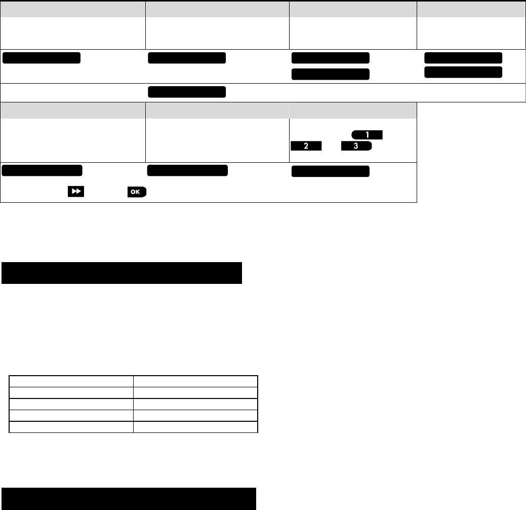
2.2. Enrollment
Refer to the PowerMaster panel's Installer's Guide and follow the procedure under the "02:ZONES/DEVICES" option of the Installer
Menu. A general description of the procedure is provided in the following flow chart.
Step 1 Step 2 Step 3 Step 4
Enter the Installer menu and select
“02:ZONES/DEVICES” Select "ADD NEW DEVICE"
See Note 1
Enroll the device or enter the
device ID Select the desired detector
number for the new flood
detector
Step 5 Step 6 Step 7
Configure Location parameter Enter PARTITIONS.
See Note 2
Assign partitions to the detector
by pressing the ,
and buttons on
the panel
means scroll and select
Notes:
1. If the detector is already enrolled, you can configure the detector location parameter and assign partitions via the “Modify Devices”
option – see Step 2.
2. PARTITIONS will appear only if PARTITIONING was previously enabled in a panel that supports the Partitioning feature (for further
details, see "Partitioning" in the PowerMaster Installer Guide).
3. LOCAL DIAGNOSTICS TEST
Before testing, separate the base from the cover (see Figure 2).
A. Verify that the FLD-550 transmits (the LED lights briefly) and that a tamper message was received by the panel.
B. When you are satisfied that tamper alerts are transmitted properly, put the cover on to return the tamper switch to its normal
(undisturbed) position and then secure the front cover to the base with the screw.
C. Bring the flood sensor into contact with water. Wait a few seconds and verify that the transmitter LED lights, indicating that
transmission is in progress. It is recommended to perform this test every month.
D. After 2 seconds the LED blinks 3 times.
The following table indicates received signal strength indication.
LED response Reception
Green LED blinks Strong
Orange LED blinks Good
Red LED blinks Poor
No blinks No communication
IMPORTANT! Reliable reception must be assured. Therefore, "poor" signal strength is not acceptable. If you receive a "poor" signal
from the device, re-locate it and re-test until a "good" or "strong" signal strength is received.
E. Dry the flood sensor using either blotting paper or a rag, thus restoring it to the undisturbed state, and then observe the LED.
Note: For detailed Diagnostics Test instructions refer to the control panel Installer's Guide.
4. MISCELLANEOUS COMMENTS
Visonic Ltd. wireless systems are very reliable and are tested to high standards. However, due to low transmitting power and limited
range (required by FCC and other regulatory authorities), there are some limitations to be considered:
A. Receivers may be blocked by radio signals occurring on or near their operating frequencies, regardless of the digital code used.
B. A receiver responds only to one transmitted signal at a time.
C. Wireless devices should be tested regularly to determine whether there are sources of interference and to protect against faults.
The user is cautioned that changes or modifications to the unit, not expressly approved by Visonic Ltd., could void the user’s
FCC or other authority to operate the equipment.
The digital circuitry of this device has been tested and found to comply with the limits for a Class B digital device, pursuant to Part 15 of
the FCC Rules. These limits are designed to provide reasonable protection against harmful interference in residential installations. This
equipment generates, uses and can radiate radio frequency energy and, if not installed and used in accordance with the instructions,
may cause harmful interference to radio and television reception. However, there is no guarantee that interference will not occur in a
particular installation. If this device does cause such interference, which can be verified by turning the device off and on, the user is
encouraged to eliminate the interference by one or more of the following measures:
– Re-orient or re-locate the receiving antenna.
– Increase the distance between the device and the receiver.
– Connect the device to an outlet on a circuit different from the one which supplies power to the receiver.
– Consult the dealer or an experienced radio/TV technician
MODIFY DEVICES
Z07.LOCATION Z07.PARTITIONS Z07:P1 P2 P3
ID No. 240-XXXX
Z07:Flood Sens
ENTR ID:XXX-XXXX
ENROLL NOW or ADD NEW DEVICES
02:ZONES/DEVICES
D-303731 FLD-550 PG2 Installation Instructions 3
5. COMPLIANCE WITH STANDARDS
Compliance with Standards
Europe (433, 868 MHz): EN 300220, EN 301489, EN 60950
USA (915 MHz): CFR 47 part 15 (FCC)
Canada (915 MHz): RSS 210
This device complies with Part 15 of the FCC Rules and with Industry Canada license-exempt
RSS standard(s). Operation is subject to the following two conditions: (1) This device may not
cause harmful interference, and (2) this device must accept any interference received, including
interference that may cause undesired operation.
Le présent appareil est conforme aux CNR d'Industrie Canada applicables aux appareils radio
exempts de licence. L'exploitation est autorisée aux deux conditions suivantes :
(1) l'appareil ne doit pas produire de brouillage, et (2) l'utilisateur de l'appareil doit accepter tout
brouillage radioélectrique subi, même si le brouillage est susceptible d'en compromettre le
fonctionnement.
This device complies with the essential requirements and provisions of Directive 1999/5/EC of the
European Parliament and of the Council of 9 March 1999 on radio and telecommunications
terminal equipment.
WARNING! To comply with FCC and IC RF exposure compliance requirements, the device should be
located at a distance of at least 20 cm from all persons during normal operation. The antennas used
for this product must not be co-located or operated in conjunction with any other antenna or
transmitter.
The Power G peripheral devices have two- way communication functionality, providing additional benefits as described in
the technical brochure. This functionality has not been tested to comply with the respective technical requirements and
should therefore be considered outside the scope of the product’s certification.
The technical documentation as required by the European Conformity Assessment procedure is kept at:
UNIT 6 MADINGLEY COURT CHIPPENHAM DRIVE KINGSTON MILTON KEYNES MK10 0BZ. TEL.: +44(0)845 0755800 FAX: +44(0)845 0755801
W.E.E.E. Product Recycling Declaration
For information regarding the recycling of this product you must contact the company from which you orignially purchased it. If you are discarding this product and not
returning it for repair then you must ensure that it is returned as identified by your supplier. This product is not to be thrown away with everyday waste.
Directive 2002/96/EC Waste Electrical and Electronic Equipment.
APPENDIX: SPECIFICATIONS
Frequency Band (MHz) Europe and rest of world: 433-434, 868-869 USA: 912-919
Communication Protocol PowerG
Alarm Input External flood probe
Supervision Signaling at 4-min. intervals
Tamper Alert Reported when a tamper event occurs
Power Supply Type C
Battery type 3 V Lithium CR-123 type battery, Panasonic, Sanyo or GP only.
Battery Life Expectancy 8 years (for typical use)
Battery Supervision Automatic transmission of battery condition data as part of periodic status report and immediately
upon low battery condition detection
Operating Temperature 0C to 49C (32F to 120F)
Humidity Average relative humidity of approximate 75% non-condensing. For 30 days per year relative
humidity may vary between 85 % and 95 % non-condensing
Dimensions (LxWxD) 81 x 34 x 25 mm (3-3/16 x 1-1/4 x 1 in.)
Weight (including battery) 53g (1.9 oz)

4 D-303731 FLD-550 PG2 Installation Instructions
WARRANTY
Visonic Limited (the “Manufacturer") warrants this product only (the "Product") to the original purchaser only (the
“Purchaser”) against defective workmanship and materials under normal use of the Product for a period of twelve
(12) months from the date of shipment by the Manufacturer.
This Warranty is absolutely conditional upon the Product having been properly installed, maintained and operated
under conditions of normal use in accordance with the Manufacturers recommended installation and operation
instructions. Products which have become defective for any other reason, according to the Manufacturers
discretion, such as improper installation, failure to follow recommended installation and operational instructions,
neglect, willful damage, misuse or vandalism, accidental damage, alteration or tampering, or repair by anyone
other than the manufacturer, are not covered by this Warranty.
The Manufacturer does not represent that this Product may not be compromised and/or circumvented or that the
Product will prevent any death and/or personal injury and/or damage to property resulting from burglary, robbery,
fire or otherwise, or that the Product will in all cases provide adequate warning or protection. The Product,
properly installed and maintained, only reduces the risk of such events without warning and it is not a guarantee
or insurance that such events will not occur.
THIS WARRANTY IS EXCLUSIVE AND EXPRESSLY IN LIEU OF ALL OTHER WARRANTIES, OBLIGATIONS
OR LIABILITIES, WHETHER WRITTEN, ORAL, EXPRESS OR IMPLIED, INCLUDING ANY WARRANTY OF
MERCHANTABILITY OR FITNESS FOR A PARTICULAR PURPOSE, OR OTHERWISE. IN NO CASE SHALL
THE MANUFACTURER BE LIABLE TO ANYONE FOR ANY CONSEQUENTIAL OR INCIDENTAL DAMAGES
FOR BREACH OF THIS WARRANTY OR ANY OTHER WARRANTIES WHATSOEVER, AS AFORESAID.
THE MANUFACTURER SHALL IN NO EVENT BE LIABLE FOR ANY SPECIAL, INDIRECT, INCIDENTAL,
CONSEQUENTIAL OR PUNITIVE DAMAGES OR FOR LOSS, DAMAGE, OR EXPENSE, INCLUDING LOSS
OF USE, PROFITS, REVENUE, OR GOODWILL, DIRECTLY OR INDIRECTLY ARISING FROM
PURCHASER’S USE OR INABILITY TO USE THE PRODUCT, OR FOR LOSS OR DESTRUCTION OF
OTHER PROPERTY OR FROM ANY OTHER CAUSE, EVEN IF MANUFACTURER HAS BEEN ADVISED OF
THE POSSIBILITY OF SUCH DAMAGE.
THE MANUFACTURER SHALL HAVE NO LIABILITY FOR ANY DEATH, PERSONAL AND/OR BODILY
INJURY AND/OR DAMAGE TO PROPERTY OR OTHER LOSS WHETHER DIRECT, INDIRECT, INCIDENTAL,
CONSEQUENTIAL OR OTHERWISE, BASED ON A CLAIM THAT THE PRODUCT FAILED TO FUNCTION.
However, if the Manufacturer is held liable, whether directly or indirectly, for any loss or damage arising under this
limited warranty, THE MANUFACTURER'S MAXIMUM LIABILITY (IF ANY) SHALL NOT IN ANY CASE
EXCEED THE PURCHASE PRICE OF THE PRODUCT, which shall be fixed as liquidated damages and not as a
penalty, and shall be the complete and exclusive remedy against the Manufacturer.
When accepting the delivery of the Product, the Purchaser agrees to the said conditions of sale and warranty and
he recognizes having been informed of.
Some jurisdictions do not allow the exclusion or limitation of incidental or consequential damages, so these
limitations may not apply under certain circumstances.
The Manufacturer shall be under no liability whatsoever arising out of the corruption and/or malfunctioning of any
telecommunication or electronic equipment or any programs.
The Manufacturers obligations under this Warranty are limited solely to repair and/or replace at the
Manufacturer’s discretion any Product or part thereof that may prove defective. Any repair and/or replacement
shall not extend the original Warranty period. The Manufacturer shall not be responsible for dismantling and/or
reinstallation costs. To exercise this Warranty the Product must be returned to the Manufacturer freight pre-paid
and insured. All freight and insurance costs are the responsibility of the Purchaser and are not included in this
Warranty.
This warranty shall not be modified, varied or extended, and the Manufacturer does not authorize any person to
act on its behalf in the modification, variation or extension of this warranty. This warranty shall apply to the
Product only. All products, accessories or attachments of others used in conjunction with the Product, including
batteries, shall be covered solely by their own warranty, if any. The Manufacturer shall not be liable for any
damage or loss whatsoever, whether directly, indirectly, incidentally, consequentially or otherwise, caused by the
malfunction of the Product due to products, accessories, or attachments of others, including batteries, used in
conjunction with the Products. This Warranty is exclusive to the original Purchaser and is not assignable.
This Warranty is in addition to and does not affect your legal rights. Any provision in this warranty which is
contrary to the Law in the state or country were the Product is supplied shall not apply.
Warning: The user must follow the Manufacturer’s installation and operational instructions including testing the
Product and its whole system at least once a week and to take all necessary precautions for his/her safety and
the protection of his/her property.
1/08
VISONIC LTD. (ISRAEL): P.O.B 22020 TEL-AVIV 61220 ISRAEL. PHONE: (972-3) 645-6789, FAX: (972-3) 645-6788
VISONIC INC. (U.S.A.): 65 WEST DUDLEY TOWN ROAD, BLOOMFIELD CT. 06002-1376. PHONE: (860) 243-0833, (800) 223-0020. FAX: (860) 242-8094
VISONIC LTD. (UK): UNIT 6 MADINGLEY COURT CHIPPENHAM DRIVE KINGSTON MILTON KEYNES MK10 0BZ.
VISONIC GmbH (D-A-CH): KIRCHFELDSTR. 118, D-40215 DÜSSELDORF, TEL.: +49 (0)211 600696-0, FAX: +49 (0)211 600696-19
VISONIC IBERICA: ISLA DE PALMA, 32 NAVE 7, POLÍGONO INDUSTRIAL NORTE, 28700 SAN SEBASTIÁN DE LOS REYES, (MADRID), ESPAÑA. TEL (34) 91659-3120,
FAX (34) 91663-8468. www.visonic-iberica.es
INTERNET: www.visonic.com
VISONIC LTD. 2012 FLD-550 PG2 D-303731 (REV. 0, 2/12)