Users Manual
D-303404 GSD-442 PG2 Installation Instructions 1
GSD-442 PG2
PowerG Wireless Carbon Monoxide (CO) Detector Installation Instructions
1. INTRODUCTION
The Wireless PowerG Two-way Carbon Monoxide (CO) Detector is designed to monitor the CO gas level in residential dwellings and
give early warning before potentially dangerous levels exist. The CO alarm is transmitted to the PowerMaster control panel and
presented on its display.
The CO gas is considered to be a highly dangerous poisonous gas because it is colorless, odorless, tasteless and very toxic. Presence
of CO gas inhibits the blood's capacity to transport oxygen throughout the body, which can eventually lead to brain damage. CO gas is
produced by incomplete combustion of fuels (such as natural gas, propane, heating oil, kerosene, coal, charcoal, gasoline or wood) that
can occur in any device that depends on burning for energy and heat (such as furnaces, boilers, room heaters, hot water heaters, stoves,
grills and in any gasoline powered vehicle or engine).
Before CO harmful level is reached, the detector's internal buzzer beeps sound periodically
and the detector's red LED flashes. In this condition, the buzzer sound can be stopped for 6
minutes by pressing the TEST/MUTE switch. It will not correct the CO gas problem, but will
temporarily silence the buzzer while you correct the problem. After 6 minutes, the detector
restarts alarm if the CO level remains high.
The detector provides low battery and detector end-of-life indications.
Caution: The detector expiry date is stamped on the detector. After the expiry date, the
detector should not be used - do not wait for end-of-life indication!!
The detector is continuously self-tested and has a TEST button that enables the user to test
the detector anytime.
Note: The TEST/MUTE switch functions as TEST switch (in normal operation) or as MUTE
switch (in alarm condition).
The tamper switch actuator (Figure 3), is pressed against the bracket when the unit is
attached to the bracket. Removal of the unit from the bracket causes the switch contacts to
open, creating a tamper event, which is reported by the transmitter to the alarm system
control panel.
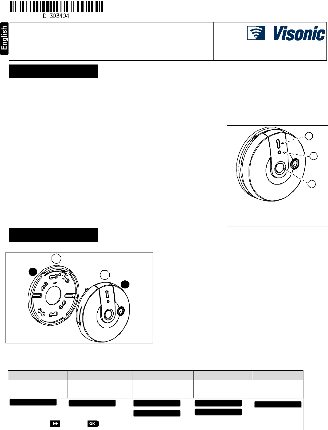
A
B
C
A. Alarm (red) LED
B. Battery (green) / Fault (yellow) LED
C. TEST / MUTE button
Figure 1 - General View
2. PREPARATIONS
2.1 Disassembly
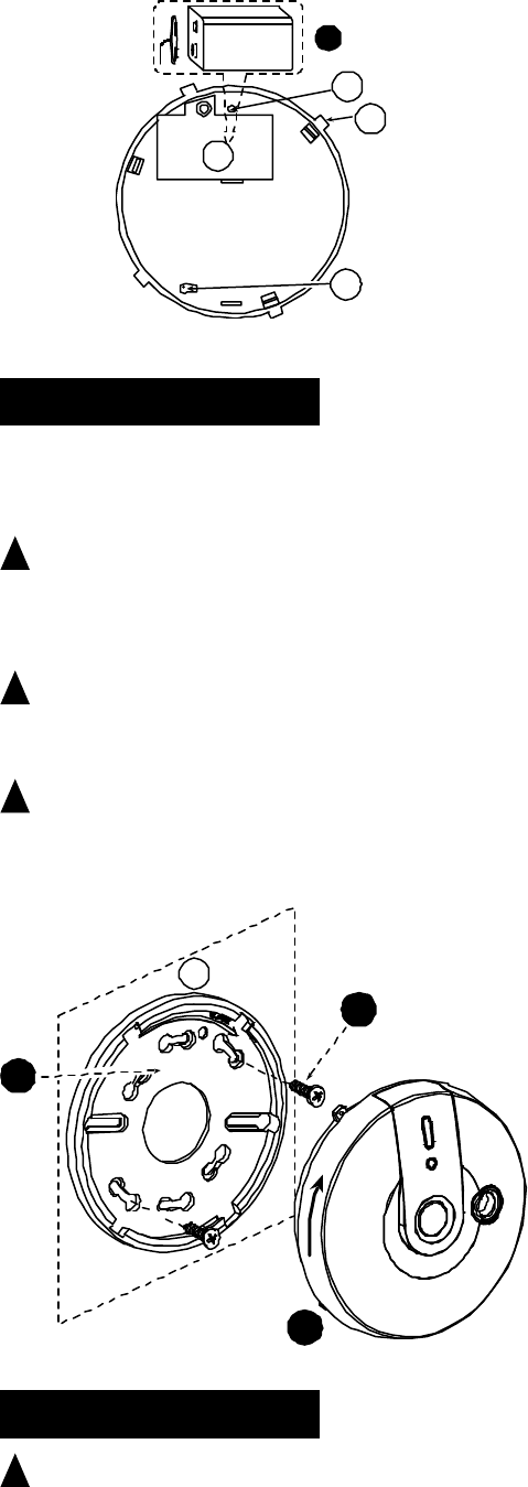
1
2
A
B
1. Hold the bracket with one hand
2. Rotate the detector as shown and pull it from the bracket
A. Bracket
B. Detector
Figure 2. Separating the Detector from Its Bracket
2.2 Enrollment
Refer to the PowerMaster Installer Guide and follow the procedure under the "02:ZONES/DEVICES" option of the Installer Menu. A general
description of the procedure is provided in the following flow chart.
Step 1 Step 2 Step 3 Step 4 Step 5
Enter the Installer menu
and select
“02:ZONES/DEVICES”
Select "ADD NEW
DEVICE" Option
Enroll the device or Enter
the device ID
See Note
Select the desired Zone
Number
Configure the
Location Parameter
means scroll and select
Note:
i) Insert the battery (see Figure 3) to enroll the gas detector.
-or-
ii) Key in the device ID of the gas detector and at a later stage, when the installation makes possible, insert the battery.
Z07.LOCATION
IDNo.220‐XXXX
Z07:GASSensor
ENTRID:XXX‐XXXX
ENROLLNOWor
ADD
NEWDEVICES
02.ZONES/DEVICES
2 D-303404 GSD-442 PG2 Installation Instructions
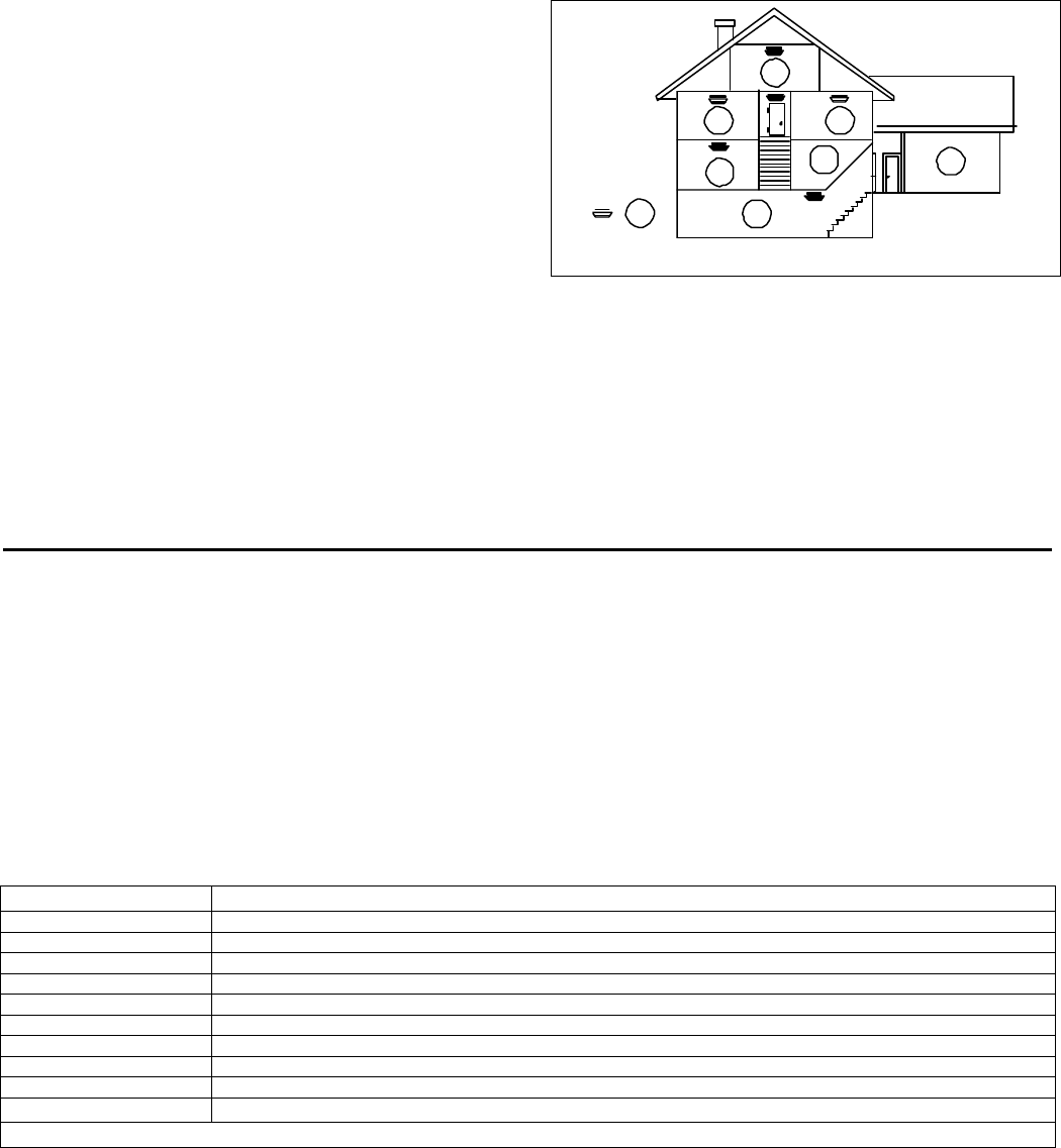
2.3 Inserting Battery
9 volts 1
AC
B
D
Insert battery (see figure 3).
1. Open the battery cover and connect the battery to its terminals without
the insulator. Verify proper polarity.
A. Red button
B. Battery connector
C. Tab (1 of 4)
D. Tamper switch actuator
Caution! Risk of explosion if battery is replaced by an incorrect type.
Dispose of used batteries according to the manufacturer's instructions.
Figure 3. Detector Rear Side
3. INSTALLATION
3.1 Mounting
The detector can be mounted on a wall or ceiling. For EN approved sites, only ceiling installation is allowed.
It must be mounted with its bracket (when it is attached to its bracket the tamper switch is pressed and the detector automatic reset is
performed).
! Warnings
Installation must be performed by a qualified individual. Failure to properly install, test and maintain a CO detector may cause it to fail,
resulting in loss of life!
Installation of the CO detector should not be used as a substitute for proper installation, use and maintenance of fuel burning
appliances, including appropriate ventilation and exhaust systems.
Unauthorized removal of the unit from the bracket will initiate a tamper alert!
! Warning - The battery must be inserted into the detector otherwise you will not be able to close the detector.
3.2 Diagnostic Test
For Diagnostics Test instructions refer to the control panel Installer Guide.
! WARNING: The test switch is the only proper way to test the CO detector. Never use vehicle exhaust! Exhaust may cause
permanent damage and void your warranty.
B. Communication Test
Create a tamper alarm at the installation location and verify that tamper message is received by the control panel / receiver.
1
2
3
UP
A
1. Locate the bracket on the mounting surface so that the word
"UP" appears in the direction shown in Figure 4 (this ensures
that the text on the detector's stickers will be easily readable).
2. Mark and drill 2 holes in the mounting surface. Fasten the
bracket to the mounting surface with 2 screws.
3. Align the detector's tabs (see Figure 3) with the bracket slots
and rotate the detector as shown. Pull the detector outward to
verify that it is securely attached.
A. Mounting Surface
Figure 4. Mounting
4. MAINTENANCE
! Warning: Press the detector's TEST button once every week to ensure proper operation of the detector.
When low battery alarm exists (see specifications) immediately replace the battery (see figure 3).
Once a month, use a vacuum cleaner to clean the air vents occasionally, to keep them free of dust.

D-303404 GSD-442 PG2 Installation Instructions 3
APPENDICES
Appendix A - Specifications
CO DETECTION
Detection Principle Electrochemical cell
Detector Active Life 5 years
Selectable Sensitivity DIP switch in EN mode:
No warning at 30 ppm for 120 minutes, 50 ppm for 60 minutes, 100 ppm for 10 minutes.
Warning at 50 ppm between 60-90 minutes, 100 ppm for 10-40 minutes, 150 ppm within 3 minutes
DIP switch in UL mode:
No warning at 30 ppm for 30 days,, 70 ppm for 60 minutes, 150 ppm for 10 minutes, 400 ppm for 4
minutes.
Warning at 70 ppm between 60-240 minutes, 150 ppm for 10-50 minutes, 400 ppm between 4-15minutes
Audible Alarm Volume >85db at a distance of 3m (10 ft.)
WIRELESS
Frequency Band (MHz) Europe and rest of world: 433-434, 868-869 USA: 912-919
Communication Protocol PowerG
Supervision Automatic signaling at 60-minute intervals (912-919 MHz version), 15-minute intervals (433-434, 868-869
versions) or according to the local standards.
Transmitted Messages CO gas alarm, low battery, tampe
r
, trouble message as a result of sensor end of life or sensor trouble,
supervision.
Tamper Alerts Tamper message is transmitted to the PowerMaster control panel when the detector is removed from its
bracket.
ELECTRICAL DAT
A
Power Source 9 Volt Lithium battery (Ultra Life #U9VL-J-P), or Alkaline battery, Energizer #522.
Note: For UL, use only Energizer #522.
Current Drain 55 μA average current consumption. For UL, 42 μA standby, 22.2 mA in alarm.
Battery Supervision Automatic transmission of battery status data as part of any transmitted message.
Battery Life Expectancy At least 1 year (for typical use)
Audible and Visual
Indications Condition
V
isual Indication (LEDs) Audio
Indication
Red Yellow Green
Alarm 4 flashes (*) - - 4 beeps (*)
End of Life / Fault - 3 flashes every
60 sec.
- one beep every 60
sec.
Battery OK - - Flashes once
every minute
-
Low battery - 1 flash every 60
sec.
- One beep every 60
sec.
MUTE button is
pressed (to silent the
alarm for 6 minutes)
4 flashes (*) - - OFF for 6 minutes (**)
TEST button is
pressed
1 flash (the 1st
LED)
1 flash (the 2nd
LED)
Flashes (the 3rd
LED) If CO circuit
test and battery
are OK - lights
during 2 sec.
1 beep
* Every 5 seconds during the first 4 minutes, every 60 seconds after the first 4 minutes.
** Every 6 minutes the detector restarts the alarm if the CO level remains high.
Note: Long period of low battery condition may cause improper function. In case of End-of-Life/Fault
indication, replace the battery and check if the End-of-Life/Fault indication still exists. If it still exists, stop
using the detector.
PHYSICAL DAT
A
Operatin
g
Temperatures 0°C to 40°C
(
32°F to 104°F
)
Relative Humidity 10% to 93% 2% RH
Dimensions 127 mm (5 in.) x 40 mm (1-9/16 in.)
Wei
g
ht
(
with batter
y)
180
g
(
6.35 oz
)
Compliance with
Standards Europe: EN50291, EN 50130-4, EN 300220, EN 301489.
Note: The apparatus may not prevent the chronic effects of carbon
monoxide exposure, and the apparatus will not fully safeguard individuals at
risk.
Certified by LPCB (UK)
USA (315MHz): UL2075, CFR47 part 15.
4 D-303404 GSD-442 PG2 Installation Instructions
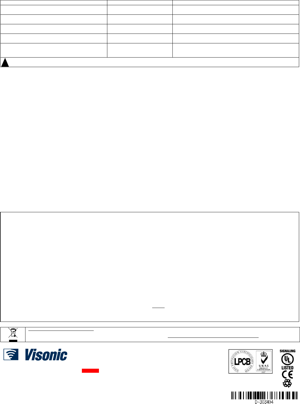
Appendix B - CO Detector Installation Overview
B-1. Selecting Installation Location
Selecting a suitable location is critical for the CO detector. The Consumer Product Safety Commission (CPSC) recommends to use at
least one CO detector per household, located near as possible to sleeping areas of the home, because the human body is most
vulnerable to the CO gas effect during sleeping hours.
For added protection, install additional CO detectors in every separate bedroom and on every level of your home. If your bedroom
hallway is longer than 14 meters (40 feet), install a CO detector at BOTH ends of the hallway. Install an additional detector 6 meters (20
feet) away from the furnace or fuel burning heat source.
For maximum protection, the detector should be also located outside
primary sleeping areas or at each level of your home. Mount the
detector on a firm wall or ceiling (see par. 3.1).
A. Bedroom
B. Living room
C. Kitchen
D. Basement
E. Garage
F. CO detector
BC
D
A
E
A A
F
Figure 5. CO Detectors locations in a Multi-Floor Residence
B-2. Where Not to Install CO Detectors
1. In locations where temperature may be below -10C (14F) or above 40C (104F).
2. In locations where humidity is below 10% or above 93% RH.
3. Near paint thinner fumes.
4. Near air conditioners, furnaces, stoves, fireplaces and any other ventilation source that may interfere with the CO gas entering the
detector.
5. In locations where furniture or draperies may obstruct the air flow.
6. In exhaust streams from gas engines, vents, flues or chimneys.
7. Where dirt or dust could collect and block the sensor and stop its working.
8. In locations that can be reached by children.
9. In turbulent air from ceiling fans.
10. In close proximity to an automobile exhaust pipe - this will damage the detector.
Appendix C - CO Gas Health Effects
C-1. Toxic Effects
Carbon monoxide (CO) is a colorless, odorless non-irritating gas which is classified as a chemical asphyxiate whose toxic action is a
direct result of the hypoxia produced by a given exposure.
CO is rapidly absorbed through the lungs, diffuses across the alveolar capillary membrane and is reversible bound with hemoglobin as
carboxyheoglobin (COHb), however a minute amount is present in the plasma. The affinity of hemoglobin for CO is over 200 times its
affinity for oxygen. This reduces the oxygen carrying of the blood and also has an effect on dissociation of oxyhemoglobin which farther
reduces the oxygen supply to the tissues. CO is chemically unchanged in the body and is eliminated in the expired air. The elimination is
determined by the same factors that are applied during absorption.
If the CO level in the inhaled air is constant, the level of COHb in the blood will approach an equilibrium state after several hours.
However, the rate at which the equilibrium is reached depends on many factors, e.g. lung ventilation rate (physical activity) and alveolar
capillary transfer, cardiac parameters, blood hemoglobin concentration, barometric pressure, oxygen and carbon dioxide concentration in
the inhaled air, but the two most important factors in determining the COHb level are the CO concentration and the duration of exposure.
The effects of different saturation blood COHb levels on healthy adults are shown in Table 1.
Table 1 - Health effects of COHb blood levels on healthy adults
% COHb Effects
03 - 0.7 Normal range in non-smokers due to endogenous production
0.7 - 2.9 No proven physiological changes
2.9 - 4.5 Cardio-vascular changes in cardiac patients
4 - 6 Usual values observed in smokers, impairment in psychomotor tests
7 - 10 Cardio-vascular changes in non-cardiac patients (increased cardiac output and coronary blood flow)
10 - 20 Slight headache, weakness, potential burden on fetus
20 - 30 Severe headache, nausea, impairment in limb movements
30 - 40 Severe headache. irritability, confusion, impairment in visual acuity, nausea, muscular weakness, dizziness
40 -50 Convulsions and unconsciousness
60 - 70 Coma, collapse, death
Source: US Environmental Protection Agency 1984
The following symptoms are related to CO poisoning and are to be discussed with ALL members of the household:
1. Mild Exposure: Slight headache, nausea, vomiting, fatigue (often described as "Flu-like" symptoms).
2. Medium Exposure: Severe throbbing headache, drowsiness, fast heart rate.
3. Extreme Exposure: Unconsciousness, convulsions, cardio respiratory failure, death.
4. Many cases of reported CO poisoning indicate that while victims are aware they are not well, they become so disordered they are
unable to save themselves by either exiting the building or calling for assistance. Young children and household pets are typically first
affected.

D-303404 GSD-442 PG2 Installation Instructions 5
C-2. Chronic Effects on High Risk Group
Individuals with coronary artery disease exposed to low levels of CO showed reduced ability to exercise. The time of onset of exercise-
induced angina pectoris in such patients exposed to low levels of CO is reduced. Carbon monoxide readily crosses the placental barrier
and may endanger the normal development of the fetus.
A number of high risk groups are particularly sensitive to the effects of CO because of various organ impairments or specific changes,
mainly:
a. Those whose oxygen carrying capacity is decreased due to anemia or other hemoglobin disorders.
b. Those with increased oxygen needs such as those encountered in fever, hyperthyroidism or pregnancy.
c. Those with systematic hypoxia due to respiratory insufficiency.
d. Those with heart disease and any vascular insufficiency, such as cerebral ischaemia and peripheral vascular diseases.
C-3. Normal COHb levels
Under normal conditions all humans have low levels of COHb of between 0.3% and 0.7% present within the body. These levels are
considered neither beneficial nor harmful.
C-4. Tobacco Smoking
Tobacco smokers are exposed to significant concentration of CO. In cigarette smokers the COHb concentration varies between 5% - 9%
while heavy smokers it may exceed 10%.
Appendix D - Action to Take When Alarm Sounds
In case of harmful levels of CO gas is detected, your detector will go into continuous full alarm, Try to take the following necessary
actions immediately:
1. Push the detector TEST switch to silence the alarm.
! Warning: Never remove the battery to silence the alarm. Removing the battery removes your protection!
2. Call your emergency service (tel. No. .............), or fire department (tel. No. ............). (Please write the telephone numbers).
3. Immediately move to fresh air - outdoors or by opening door/window. Do a head count to check that all persons are accounted for.
Do not reenter the premises nor move away from the open door/window until the emergency services responders have arrived, the
premises have been aired out, and your alarm remains in normal condition.
4. After following steps 1 - 3, if your alarm reactivates within a 24 hour period, repeat steps 1 - 3 and call a qualified technician
(Tel. No. ........) to investigate for sources of CO gas from fuel burning equipment and appliances, and inspect for proper operation of this
equipment. If problems are identified during this inspection, have the equipment serviced immediately. Note any combustion equipment
not inspected by the technician and consult the manufacturer instructions, or contact the manufacturers directly, for more information
about CO safety and this equipment. Make sure that motor vehicles are not, and have not been, operating in an attached garage or
adjacent to the residence.
! Warning: Normally an activation of the detector indicates the presence of CO gas. However, the CO gas can be extremely fatal, if it
is not detected. The source of the CO gas may come from several possible situations.
Caution: This detector will only indicate the presence of CO gas at the sensor. However, you have to be aware that the CO gas may be
present in other areas in the premises.
Action to be taken after the problem has been corrected
Once the problem about the CO gas presence in the premises has been corrected, the detector's alarm should be off. After waiting for 10
minutes, push the Test button, to verify that the detector is properly working again.
Appendix E - Warnings and Limitations
This product is intended for use in ordinary indoor locations of family living units. It is not designed to measure compliance with Occupational Safety and
Health Administration (OSHA) commercial or industrial standards.
Caution: The detector will only indicate the presence of carbon monoxide gas at the sensor. Carbon monoxide gas may be present in other areas.
Individuals with medical problems may consider using warning devices which provide audible and visual signals for carbon monoxide concentrations under
30 ppm.
The alarm, including the sensor, is not to be located within 1.5m (5 feet) of any cooking appliance.
The detector may not alarm at low carbon monoxide levels. The Occupational Safety and Health Association (OSHA) has established that continuous
exposure levels of 50 ppm should not be exceeded in an 8 hours period. Individuals with medical problem may consider more sensitive detection devices.
The CO gas detector is not suitable as a smoke detector or fire detector. This detector is not suitable to install in an hazardous location as defined in
National Electrical Code.
Carbon monoxide must reach the detector for proper performance of CO gas detection. The detector may not protect people who are at special risk from
carbon monoxide exposure by reason of age, pregnancy or medical condition. In doubt, consult your medical practitioner.
CO detectors may wear out because they contain electronic parts that fail at any time. Test your detector at least every week.
Instruct children never to play with the detector.
Never use detergents or other solvents to clean the detector.
Avoid spraying air fresheners, hair spray, paint or other aerosols near the detector.
Do not paint the detector. Paint will seal the detectors vents and interfere detecting CO gas.
Detailed information on conditions which can result in transient CO situations:
1. Excessive spillage or reverse venting of fuel burning appliances caused by:
a. Outdoor ambient conditions such as wind direction and/or velocity, including high gusts of wind; heavy air in the vent pipes (cold/humid air with
extended periods between cycles).
b. Negative pressure differential resulting from the use of exhaust fans.
c. Simultaneous operation of several fuel burning appliances competing for limited internal air.
d. Vent pipe connection vibrating loose from clothes dryers, furnaces, or water heaters.
e. Obstructions in or unconventional vent pipe designs which amplify the above situations.
2. Extended operation of unvented fuel burning devices (range, oven, fireplace, etc.).
3. Temperature inversions which can trap exhaust gasses near the ground.
4. Car idling in an open or closed attached garage, or near a home.
6 D-303404 GSD-442 PG2 Installation Instructions
Appendix F - Troubleshooting
Problem This means...
Y
ou should...
Every 60 seconds, the yellow LED flashes once and 1
beep is heard.
Low battery warning Replace battery (see SPECIFICATIONS).
When TEST/MUTE button is pressed, the green LED
flashes instead of li
g
htin
g
durin
g
2 seconds.
Detector fault o
r
the battery is
not OK.
Replace battery (see SPECIFICATIONS). If the problem still
exists, replace detecto
r
.
Every 60 seconds, the
r
e are 3 flashes of the yellow
LED and 1 beep is heard.
Detector end of life/ fault. Replace battery (see SPECIFICATIONS). If the problem still
exists, replace detector.
CO detector goes back into alarm 6 minutes after the
TEST/MUTE button is pressed.
CO level indicates a potentially
dan
g
erous situation.
If you are feeling symptoms of CO poisoning, evacuate your
home and call
y
our emer
g
enc
y
service.
CO detector alarms frequently even though no high
levels of CO are revealed in an investigation.
The CO detector may be
improperly located.
Relocate the detector - see appendix B. If frequent alarms
continue, have home rechecked for potential CO problems. You
may experiencing an intermittent CO problem.
! Warning! Changes or modifications to this equipment not expressly approved by Visonic Ltd. could void the user’s authority to operate the
equipment.
Appendix G – Compliance with Standards
WARNING! To comply with FCC and IC RF exposure compliance requirements, the device should be located at a distance of at least 20
cm from all persons during normal operation. The antennas used for this product must not be co-located or operated in conjunction with
any other antenna or transmitter.
Le dispositif doit être placé à une distance d'au moins 20 cm à partir de toutes les personnes au cours de son fonctionnement normal.
Les antennes utilisées pour ce produit ne doivent pas être situés ou exploités conjointement avec une autre antenne ou transmetteur.
The digital circuit of this device has been tested and found to comply with the limits for a Class B digital device, pursuant to part 15 of the
FCC Rules. These limits are designed to provide reasonable protection against harmful interference in a residential installation. This
equipment generates, uses and can radiate radio frequency energy and, if not installed and used in accordance with the instructions,
may cause harmful interference to radio communications. However, there is no guarantee that interference will not occur in a particular
installation. If this equipment does cause harmful interference to radio or television reception, which can be determined by turning the
equipment off and on, the user is encouraged to try to correct the interference by one or more of the following measures:
-Reorient or relocate the receiving antenna.
-Increase the separation between the equipment and receiver.
-Connect the equipment into an outlet on a circuit different from that to which the receiver is connected.
-Consult the dealer or an experienced radio/TV technician for help.
This device complies with FCC Rules Part 15 and with Industry Canada licence-exempt RSS standard(s). Operation is subject to two
conditions: (1) This device may not cause harmful interference, and (2) this device must accept any interference that may be received or
that may cause undesired operation.
Le present appareil est conforme aux CNR d'Industrie Canada applicables aux appareils radio exempts de licence. L'exploitation est
autorisee aux deux conditions suivantes :
(1) l'appareil ne doit pas produire de brouillage, et (2) l'utilisateur de l'appareil doit accepter tout brouillage radioelectrique subi, meme si
le brouillage est susceptible d'en compromettre le fonctionnement.
WARRANTY
Visonic Limited (the “Manufacturer") warrants this product only (the "Product") to the original purchaser only (the
“Purchaser”) against defective workmanship and materials under normal use of the Product for a period of
twelve (12) months from the date of shipment by the Manufacturer.
This Warranty is absolutely conditional upon the Product having been properly installed, maintained and
operated under conditions of normal use in accordance with the Manufacturers recommended installation and
operation instructions. Products which have become defective for any other reason, according to the
Manufacturers discretion, such as improper installation, failure to follow recommended installation and
operational instructions, neglect, willful damage, misuse or vandalism, accidental damage, alteration or
tampering, or repair by anyone other than the manufacturer, are not covered by this Warranty.
The Manufacturer does not represent that this Product may not be compromised and/or circumvented or that the
Product will prevent any death and/or personal injury and/or damage to property resulting from burglary,
robbery, fire or otherwise, or that the Product will in all cases provide adequate warning or protection. The
Product, properly installed and maintained, only reduces the risk of such events without warning and it is not a
guarantee or insurance that such events will not occur.
THIS WARRANTY IS EXCLUSIVE AND EXPRESSLY IN LIEU OF ALL OTHER WARRANTIES,
OBLIGATIONS OR LIABILITIES, WHETHER WRITTEN, ORAL, EXPRESS OR IMPLIED, INCLUDING ANY
WARRANTY OF MERCHANTABILITY OR FITNESS FOR A PARTICULAR PURPOSE, OR OTHERWISE. IN
NO CASE SHALL THE MANUFACTURER BE LIABLE TO ANYONE FOR ANY CONSEQUENTIAL OR
INCIDENTAL DAMAGES FOR BREACH OF THIS WARRANTY OR ANY OTHER WARRANTIES
WHATSOEVER, AS AFORESAID.
THE MANUFACTURER SHALL IN NO EVENT BE LIABLE FOR ANY SPECIAL, INDIRECT, INCIDENTAL,
CONSEQUENTIAL OR PUNITIVE DAMAGES OR FOR LOSS, DAMAGE, OR EXPENSE, INCLUDING LOSS
OF USE, PROFITS, REVENUE, OR GOODWILL, DIRECTLY OR INDIRECTLY ARISING FROM
PURCHASER’S USE OR INABILITY TO USE THE PRODUCT, OR FOR LOSS OR DESTRUCTION OF
OTHER PROPERTY OR FROM ANY OTHER CAUSE, EVEN IF MANUFACTURER HAS BEEN ADVISED OF
THE POSSIBILITY OF SUCH DAMAGE.
THE MANUFACTURER SHALL HAVE NO LIABILITY FOR ANY DEATH, PERSONAL AND/OR BODILY
INJURY AND/OR DAMAGE TO PROPERTY OR OTHER LOSS WHETHER DIRECT, INDIRECT,
INCIDENTAL, CONSEQUENTIAL OR OTHERWISE, BASED ON A CLAIM THAT THE PRODUCT FAILED TO
FUNCTION.
However, if the Manufacturer is held liable, whether directly or indirectly, for any loss or damage arising under
this limited warranty, THE MANUFACTURER'S MAXIMUM LIABILITY (IF ANY) SHALL NOT IN ANY CASE
EXCEED THE PURCHASE PRICE OF THE PRODUCT, which shall be fixed as liquidated damages and not as
a penalty, and shall be the complete and exclusive remedy against the Manufacturer.
When accepting the delivery of the Product, the Purchaser agrees to the said conditions of sale and warranty
and he recognizes having been informed of.
Some jurisdictions do not allow the exclusion or limitation of incidental or consequential damages, so these
limitations may not apply under certain circumstances.
The Manufacturer shall be under no liability whatsoever arising out of the corruption and/or malfunctioning of any
telecommunication or electronic equipment or any programs.
The Manufacturers obligations under this Warranty are limited solely to repair and/or replace at the
Manufacturer’s discretion any Product or part thereof that may prove defective. Any repair and/or replacement
shall not extend the original Warranty period. The Manufacturer shall not be responsible for dismantling and/or
reinstallation costs. To exercise this Warranty the Product must be returned to the Manufacturer freight pre-paid
and insured. All freight and insurance costs are the responsibility of the Purchaser and are not included in this
Warranty.
This warranty shall not be modified, varied or extended, and the Manufacturer does not authorize any person to
act on its behalf in the modification, variation or extension of this warranty. This warranty shall apply to the
Product only. All products, accessories or attachments of others used in conjunction with the Product, including
batteries, shall be covered solely by their own warranty, if any. The Manufacturer shall not be liable for any
damage or loss whatsoever, whether directly, indirectly, incidentally, consequentially or otherwise, caused by the
malfunction of the Product due to products, accessories, or attachments of others, including batteries, used in
conjunction with the Products. This Warranty is exclusive to the original Purchaser and is not assignable.
This Warranty is in addition to and does not affect your legal rights. Any provision in this warranty which is
contrary to the Law in the state or country were the Product is supplied shall not apply.
Warning:The user must follow the Manufacturer’s installation and operational instructions including testing the
Product and its whole system at least once a week and to take all necessary precautions for his/her safety and
the protection of his/her property. 1/08
W.E.E.E. Product Recycling Declaration
For information regarding the recycling of this product you must contact the company from which you orignially purchased it. If you are discarding this product and not
returning it for repair then you must ensure that it is returned as identified by your supplier. This product is not to be thrown away with everyday waste.
Directive 2002/96/EC Waste Electrical and Electronic Equipment.
EMAIL: info@visonic.com
INTERNET: www.visonic.com
VISONIC LTD. 2014 GSD-442 PG2 D-303404 Rev 2 (/14)
Product Certificate Number
512e/01