4 pages
DE1835 1
/2*,&$/2*,&$$0
Dual-Technology Microwave/PIR Intrusion Detectors Installation Instructions
)($785(6
• Cylindrical optics improves detection and false alarm immunity.
• True Motion Recognition™ (TMR) algorithm (patented) distin-
guishes between the true motion of a human body and other
disturbances which invariably cause false alarms
• DRO-stabilized MW microstrip technology (patented)
• MW Motion Simulator simulates the effect of a human body
moving in the MW field (for MW self-test - patent pending)
• Range control for adjusting the MW coverage
• Integral swivel bracket for wall or ceiling installation
• Sealed chamber protects the pyroelectric element from insects.
• PIR self-test by applying a short heat pulse (LOGICA-AM only)
• Programmable motion event
counter (1 or 2 events)
• Simple-to-use, two-position
vertical adjustment
• TEST input to enable/disable
the walk test LED remotely
(per new European standard)
• Open collector trouble output
• Anti-masking protection
(LOGICA-AM only)
• White light protection.
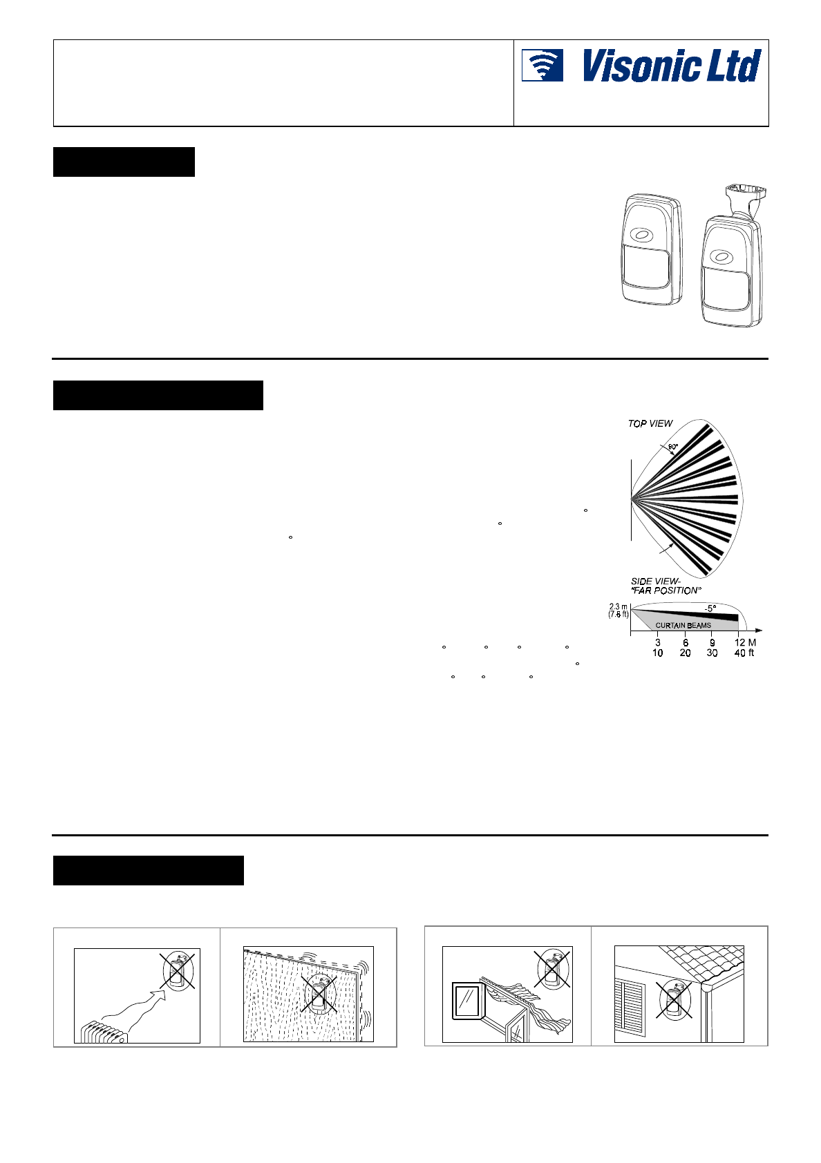
Figure 1. General View
63(&,),&$7,216
Input Voltage: 9 to 16 VDC
Current Drain: About 28 mA @ 12 VDC
PIR SECTION
Detector: Low noise dual-element pyroelectric sensor
Tripping Indication: LED flashes green for up to 5 seconds
Motion Event Verification Counter: Selectable, 1 or 2 events
Lens Data (No. 105DH - see Figure 2)
No. of Beams: 36 in two layers (curtain beams in bottom layer)
Max. Coverage: 12 x 12 m (40 x 40 ft) / 90 field of view
Vertical Adjustment: FAR and NEAR, by sliding the circuit board
along a two-position scale.
MW SECTION
Oscillator: Microstrip DRO-stabilized Doppler module
Frequency: 10.525 or 2.45 GHz
Detection Range: Adjustable from 25% to 100% (3 m to 12 m)
Tripping Indication: LED glows green for up to 5 seconds
ALARM, TAMPER & TROUBLE DATA
Alarm Indication: LED glows red for 1.3 to 5 seconds if both
detectors trip
Relay Contacts: N.C., rated at 0.1 A resistive / 30 VDC; 18 Ω
resistor in series with contacts
Alarm Duration: 1.3 to 5 seconds
Tamper Switch: N.C., rated at 50 mA resistive / 30 VDC
Trouble Output: Open collector, 100 mA max., with 18Ω resistor
in series and 47 kΩ pull-up (see Figure 11)
Masking Detection Delay (LOGICA-AM only): About 60 seconds
Trouble/ Masking Indication: LED alternately flashes green and
red and TRB output pulls LOW until the detector is reset.
MOUNTING
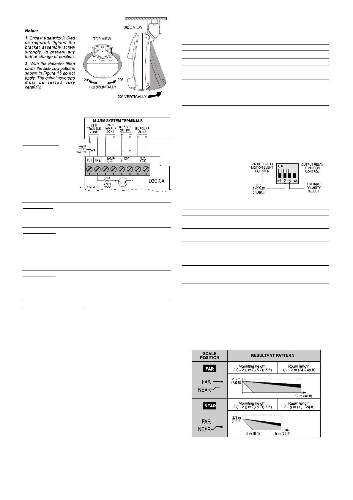
Height: Up to 3.6 m (12 ft)
Room Size: 8 - 12 m (24 -
40 ft) in the “FAR” position;
2 - 8 m (6 - 24 ft) in the NEAR
position.
Bracket Adjustment: 20
downward, 20 left and right.
Installation Options: Surface
or corner (without bracket);
surface or ceiling (with bracket)
ENVIRONMENTAL
RFI Protection: >30 V/m up to
1000 MHz.
Operating Temperatures:
-10 C to 50 C (14 F to 122 F).
Storage Temperatures: -20 C
to 60 C (-4 F to 140 F).
Figure 2. Coverage Pattern
Compliance with Standards: Complies with Part 15 of the FCC
Rules. Meets the European Council Directive EMC 89/336/EEC &
92/31/EEC, and bears the CE mark and certification.
PHYSICAL
Size (H x W x D): 117 x 65 x 47 mm (4-5/8 x 2-9/16 x 1-7/8 in.).
Weight: 109 g (3.85 oz) without bracket, 124 g (4.4 oz) with
bracket.
PATENTS
U.S. Patents 5,237,330 and 5,693,943 (other patents pending)
,167$//$7,21
,QVWDOODWLRQ+LQWV
To minimize false alarms:
Do not aim at heat sources Mount on solid, stable surfaces Do not expose to air drafts Do not install outdoors
2DE1835
Prevent direct sunlight from
reaching the detector Keep wiring away from
electrical power cables
Do not install behind partitions
In addition, a few important rules must be observed while selecting a
mounting location:
A. Microwave radiation passes through glass and non-metallic walls.
Be sure to adjust the MW range so that it does not exceed the
room limits, or else motion in the next room or moving traffic
along the outer side of the wall will cause the MW detector to trip.
B. Large reflecting objects (especially metals) in the coverage area
can distort the microwave detector's coverage pattern.
C. If two LOGICA units are installed in the same room or on opposite
sides of a shared wall, they should not face each other and must
be mounted at least 2 meters apart.
D . Do not install the LOGICA in places where one of the two
detector circuits alarms constantly or intermittently, due to
environmental interference.
E . LOGICA-AM users are advised to mount the unit in locations
where inadvertent approach to less than 1 m (3 ft) from the
detector is unlikely to occur.
0RXQWLQJZLWKRXW6ZLYHO%UDFNHW
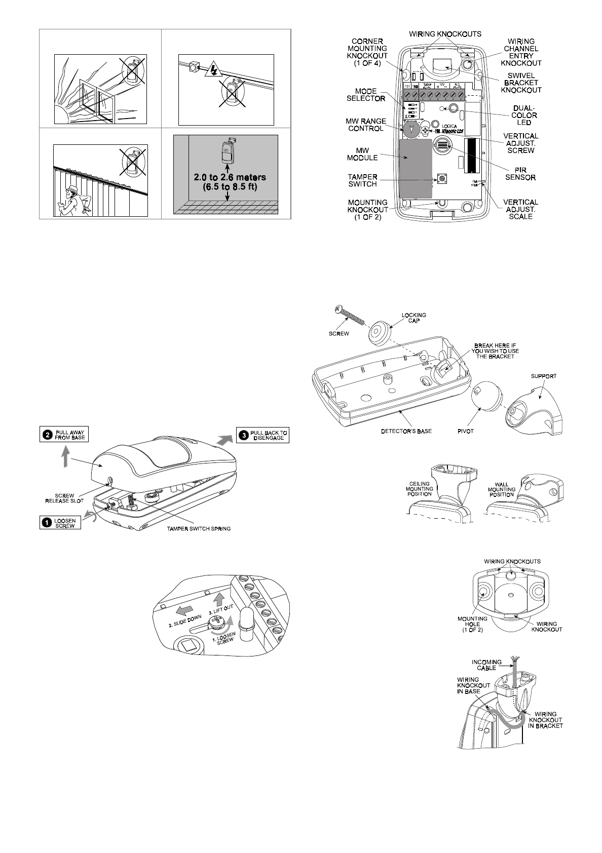
A . Remove the front cover as shown in Figure 3.
Figure 3. Cover Removal
B . Loosen the vertical adjustment screw, slide the PCB down and
remove it via the “keyhole” (see Figure 4).
C . Pull the PCB straight
out and put it aside until
required again.
D . Refer to Figure 5 and
punch out the mounting
knockouts at the rear
wall of the base (for
surface mounting) or at
the angled sides (for
corner mounting).
Figure 4. PCB Removal
E. Punch out any one of the wiring knockouts shown in Figure 5.
F. Hold the base against the wall at the selected installation
location, mark the points for drilling and drill the holes (insert
the plastic dowels supplied if necessary).
G. Pass the wires through the wiring inlets into the base and
attach the base to the wall using the screws supplied.
H. Return the PCB to its place within the base.
I. Proceed to wire the terminal block as instructed in Para. 3.5.
Figure 5. Inside View
0RXQWLQJZLWK6ZLYHO%UDFNHW
A . Remove the front cover as shown in Figure 3.
B . Remove the PCB (see Figure 4) and put it temporarily aside.
C. Punch out the large knockout in the round bulge at the top part of
the base (see Figure 6)
Figure 6. Attaching the Bracket
D . Assemble the
bracket as shown
in Figure 6.
E . Rotate the
bracket to the
desired position
(refer to Figure 7)
but do not yet
tighten the screw
fully.
Figure 7. Wall and Ceiling Positions
F . Punch out the selected wiring
knockouts in the bracket base
(see Fig. 8).
G . Press the bracket against the
mounting surface and mark the
points for drilling. Drill out the
holes and insert plastic dowels,
if necessary. Attach to the wall
with the 2 screws.
Figure 8. Bracket Rear
H . Route the cable through
the bracket and into the
detector as shown in
Figure 9.
I . Attach the bracket to the
mounting surface using the
two screws supplied.
J. Tilt down or swivel the
detector to face the desired
direction. Fig. 10 shows the
various possibilities of tilting
and swiveling.
Figure 9. Routing the Cable
DE1835 3
Figure 10. Tilt/Swivel Limits
:LULQJ
Refer to Figure 11
and connect wires to
the terminal block in
the following order:
Terminal: TAMP
(tamper switch)
Connect to: Normally
closed 24-hour tamper
zone of the control
panel.
Details: Upon remo-
val of the cover, the
tamper contacts will
open.
Figure 11. Terminal Block Wiring
Terminal: NC (alarm relay)
Connect to: Normally closed burglar protection zone.
Details: Upon alarm or power failure, the output relay's normally
closed contacts open.
Terminal: TRB (trouble output)
Connect to: 24-hour trouble zone
Details: The TRB open collector output will be grounded upon
detector malfunction or upon masking (LOGICA-AM only), thus
triggering the trouble zone.
Alternative: A buzzer or an interface relay may be connected across
the TRB output and the 12 VDC (+) terminals.
Terminal: TST (TEST input)
Connect to: +12 VDC or ground potential (depending on the setting
of DIP switch SW-3) via a test switch.
Details: Applying the trigger voltage to the TST input will enable the
dual color LED for walk testing.
Terminals: 12 V (+) and (–)
Connect to: A power source within the range of 9 to 16 VDC.
Details: It is advisable to connect the power source only after all
other connections have been completed and rechecked. Dis- connect
the AC mains from the alarm control panel and verify that the voltage
supplied to the detector is above 9 Volts with the backup battery as
the only power source.
Note: Use RTV to seal the base opening(s) to prevent insects from
entering the detector.
7KH3RZHUXS3URFHVV
After connecting the (+) and (–) terminals to the power source, the
LOGICA starts a 60-second warm-up period, indicated by alternate
flashing of the green and red lights.
Caution! If the alternate flashing of the red and green lights does not
stop within 60 seconds, a failure has been detected by the self-test
circuitry, or, if you are dealing with the LOGICA-AM, the unit may be
masked (refer to Para. 3.6).
:KDW+DSSHQVLQ&DVHRI0DVNLQJ"
If an attempt is made to stick masking material over the lens or put
a masking object close to the lens (LOGICA-AM only), a trouble
alert will result about 60 seconds after masking:
• The LED will flash red and green alternately;
• The TRB output will pull to ground and will remain grounded until
the detector is reset (see Para. 3.14 for procedure).
9LVXDO,QGLFDWLRQV
The dual color LED is used to signal various alarm and trouble
messages as shown in Table 1 below:
Table 1. Interpreting the Visual Indications
Visual Indication Significance
None No detection
Steady green (5 s) MW walk-test detection
Flashing green PIR walk-test detection
Steady red (5 s) Alarm: MW + PIR detection
Flashing red and - Trouble or masking is being
detected by the self test circuitry, or
green (alternately) - Initial warm-up routine (stops 30
seconds after power up).
Notes:
1. During walk testing, the green light glows steadily (MW detection) or flashes
(PIR detection), depending on which one of the two detectors discovered the
movement first. Upon subsequent discovery of the movement by the other
detector, the green light goes off and the red light glows (alarm).
2. If the LED maintains alternate red and green flashing beyond the warm-up
period, a malfunction or masking has been diagnosed. Replace the unit
without delay.
0RGH6HOHFWRU
The DIP switch mode
selector is mounted on
the unit’s PC board (see
Figure 5). It controls four
functions as demons-
trated in Figure 12 and as
detailed in Table 2.
Figure 12. DIP Switch Mode Selector
Table 2. Mode Selector Switch functions
Switch State Function Default
SW-1 OFF One motion event trips the PIR ON
ON Two motion events trip the PIR
SW-2 OFF The walk-test LED is disabled* ON
ON The walk-test LED is enabled
SW-3 OFF Ground potential (–) enables the LED; OFF
floating terminal disables the LED
ON Floating terminal (or +12VDC) enables
the LED; ground potential disables test.
SW-4 OFF Output relay opens upon alarm OFF
ON Output relay opens upon alarm and
also when trouble is detected.
*
The LED may be enabled remotely with a test switch connected to
the TST input as shown in Figure 11.
9HUWLFDO$GMXVWPHQW
The vertical adjustment scale for the PIR detector is located at the
lower right edge of the PC board (refer to Figure 5). Two positions
are available - FAR and NEAR. All new LOGICA units are set to the
FAR position. To adjust, loosen the vertical adjustment screw, slide
the PC board along the vertical slot until the pointer indicates the
required position on the scale (see Figure 13). When done, tighten
the adjustment screw firmly.
Figure 13. Vertical Adjustment
4DE1835
6HWWLQJWKH0RWLRQ(YHQW&RXQWHU
If you wish to set the PIR detector for maximum false alarm
immunity, shift DIP switch No. 1 (SW-1) to ON. In this position, two
consecutive motion events are required to trip the PIR detector. For
faster catch performance, shift SW-1 to OFF. In this position, only
one motion event is required to trip the PIR detector.
3,5:DON7HVW
A. Rotate the MW RANGE control fully counterclockwise to MIN.
B. Verify that DIP switch SW-2 is set to ON (the LED is enabled).
C. Mount the front cover in place.
D. Walk into the detector's field of view at the expected far edge
of the coverage area. The green light should flash for up to 5
seconds each time your motion is detected.
Note: If the green light glows steadily for up to 5 seconds,
your motion has been detected by the MW detector.
E. If PIR detection is not obtained at the far end of the coverage
area, remove the front cover and re-adjust the vertical
position. Replace the cover and retest.
0::DON7HVW
A. Remove the front cover.
B. Verify that the MW RANGE control is set fully counterclockwise
to MIN and that DIP switch SW-2 is set to ON (LED is enabled).
C. Start by moving into the coverage area at the far edge. The
LED should light green for up to 5 seconds each time your
motion is detected.
D. If your motion was not detected at the far edge, advance the
MW RANGE control slightly clockwise toward MAX and try
again until your motion is detected reliably at the far edge.
Caution! The MW detection range must not exceed the far
edge of the desired coverage area.
E. Walk across the coverage area at various ranges and verify
that your motion is consistently detected.
Note: If PIR trips interfere with your test, disable the PIR by
inserting a small piece of cardboard in front of the sensor.
$ODUP:DON7HVW
A. Set DIP switch SW-2 to ON (the LED is enabled).
B. Install the front cover in place.
C. Walk across the detector’s field of view in different directions,
at various distances from the detector, and verify proper
alarming throughout the detector's coverage area (the red
light glows for 1.3 to 5 seconds).
D. When done, remove the cover and set DIP switch SW-2 to
OFF to prevent unauthorized tracing of the coverage pattern.
E. Remount the cover and fasten it to the base using the small
screw at the bottom.
Attention! To assure proper function of the detector, the range
and coverage area should be checked at least twice a year.
Furthermore, it is recommended that users perform a walk test
at the far end of the coverage pattern to assure an alarm signal
prior to each time the alarm system is armed.
5HVHWWLQJDIWHU7URXEOH
In case of trouble alert, proceed as follows:
• Search for masking material on the lens or a masking object in
front of the lens and remove them, if found.
• Reset the detector by walk testing: cross its field of view at the
far end, causing it to alarm several times.
If everything is back to normal, the LED should stop flashing, and
the TRB output should revert to the open-circuit state (dis-
connected from the ground).
Note: If walk testing does not cause the trouble alert to stop,
recheck for masking. Once masking is ruled out, the trouble is
probably due to defective PIR or MW circuitry. Replacing the
detector unit will solve this problem.
0,6&(//$1(286&200(176
This device has been tested and found to comply with the limits for a
Class B digital device, pursuant to Part 15 of the FCC Rules. These
limits are designed to provide reasonable protection against harmful
interference in residential installations. This equipment generates,
uses and can radiate radio frequency energy and, if not installed and
used in accordance with the instructions, may cause harmful
interference to radio and television reception. However, there is no
guarantee that interference will not occur in a particular installation. If
this device does cause such interference, which can be verified by
turning the device off and on, the user is encouraged to eliminate the
interference by one or more of the following measures:
– Re-orient or re-locate the receiving antenna.
– Increase the distance between the device and the receiver.
– Connect the device to an outlet on a circuit different from the one
which supplies power to the receiver.
– Consult the dealer or an experienced radio/TV technician.
Visonic Ltd. and/or its subsidiaries and its affiliates ("the Manufacturer") warrants its
products hereinafter referred to as "the Product" or "Products" to be in conformance with
its own plans and specifications and to be free of defects in materials and workmanship
under normal use and service for a period of twelve months from the date of shipment by
the Manufacturer. The Manufacturer's obligations shall be limited within the warranty
period, at its option, to repair or replace the product or any part thereof. The Manufacturer
shall not be responsible for dismantling and/or reinstallation charges. To exercise the
warranty the product must be returned to the Manufacturer freight prepaid and insured.
This warranty does not apply in the following cases: improper installation, misuse,
failure to follow installation and operating instructions, alteration, abuse, accident or
tampering, and repair by anyone other than the Manufacturer.
This warranty is exclusive and expressly in lieu of all other warranties, obligations or
liabilities, whether written, oral, express or implied, including any warranty of
merchantability or fitness for a particular purpose, or otherwise. In no case shall the
Manufacturer be liable to anyone for any consequential or incidental damages for breach
of this warranty or any other warranties whatsoever, as aforesaid.
This warranty shall not be modified, varied or extended, and the Manufacturer does not
authorize any person to act on its behalf in the modification, variation or extension of this
warranty. This warranty shall apply to the Product only. All products, accessories or
attachments of others used in conjunction with the Product, including batteries, shall be
covered solely by their own warranty, if any. The Manufacturer shall not be liable for any
damage or loss whatsoever, whether directly, indirectly, incidentally, consequentially or
otherwise, caused by the malfunction of the Product due to products, accessories, or
attachments of others, including batteries, used in conjunction with the Products.
The Manufacturer does not represent that its Product may not be compromised and/or
circumvented, or that the Product will prevent any death, personal and/or bodily injury
and/or damage to property resulting from burglary, robbery, fire or otherwise, or that the
Product will in all cases provide adequate warning or protection. User understands that a
properly installed and maintained alarm may only reduce the risk of events such as
burglary, robbery, and fire without warning, but it is not insurance or a guarantee that such
will not occur or that there will be no death, personal damage and/or damage to property
as a result.
The Manufacturer shall have no liability for any death, personal and/or bodily injury
and/or damage to property or other loss whether direct, indirect, incidental,
consequential or otherwise, based on a claim that the Product failed to function.
However, if the Manufacturer is held liable, whether directly or indirectly, for any loss or
damage arising under this limited warranty or otherwise, regardless of cause or origin, the
Manufacturer's maximum liability shall not in any case exceed the purchase price of the
Product, which shall be fixed as liquidated damages and not as a penalty, and shall be the
complete and exclusive remedy against the Manufacturer.
Warning: The user should follow the installation and operation instructions and among
other things test the Product and the whole system at least once a week. For various
reasons, including, but not limited to, changes in environmental conditions, electric or
electronic disruptions and tampering, the Product may not perform as expected. The user
is advised to take all necessary precautions for his/her safety and the protection of his/her
property.
6/91
VISONIC LTD. (ISRAEL): P.O.B 22020 TEL-AVIV 61220 ISRAEL. PHONE: (972-3) 645-6789, FAX: (972-3) 645-6788
VISONIC INC. (U.S.A.): 10 NORTHWOOD DRIVE, BLOOMFIELD CT. 06002-1911. PHONE: (860) 243-0833, (800) 223-0020 FAX: (860) 242-8094
VISONIC LTD. (UK): UNIT 1, STRATTON PARK, DUNTON LANE, BIGGLESWADE, BEDS. SG18 8QS. PHONE: (01767) 600857 FAX: (01767) 601098
Internet Web Site: www.visonic.com
VISONIC LTD. 1999 LOGICA DE1835- (REV. 1, 5/99)