User Manual
D-303015 KP-140 PG2, KP-141 PG2 Installation Instructions 1
KP-140 PG2/KP-141 PG2
Portable Remote Wireless 2-Way Keypad
User’s Guide
1. INTRODUCTION
KP-140 PG2 and KP-141 PG2 are 2-way PowerG wireless keypads for the
PowerMaster family control panels. The KP-141 PG2 is the same as the KP-140
PG2 but also includes a built-in proximity RFID tag reader. Both keypads enable
most common everyday user functions:
Arm and Disarm the alarm system.
Initiate Emergency, Fire and Panic alarms.
Control X-10 devices and PGM output (not to be enabled in UL Listed product).
Perform one of the AUX (auxiliary) predefined functions.
Review system Status.
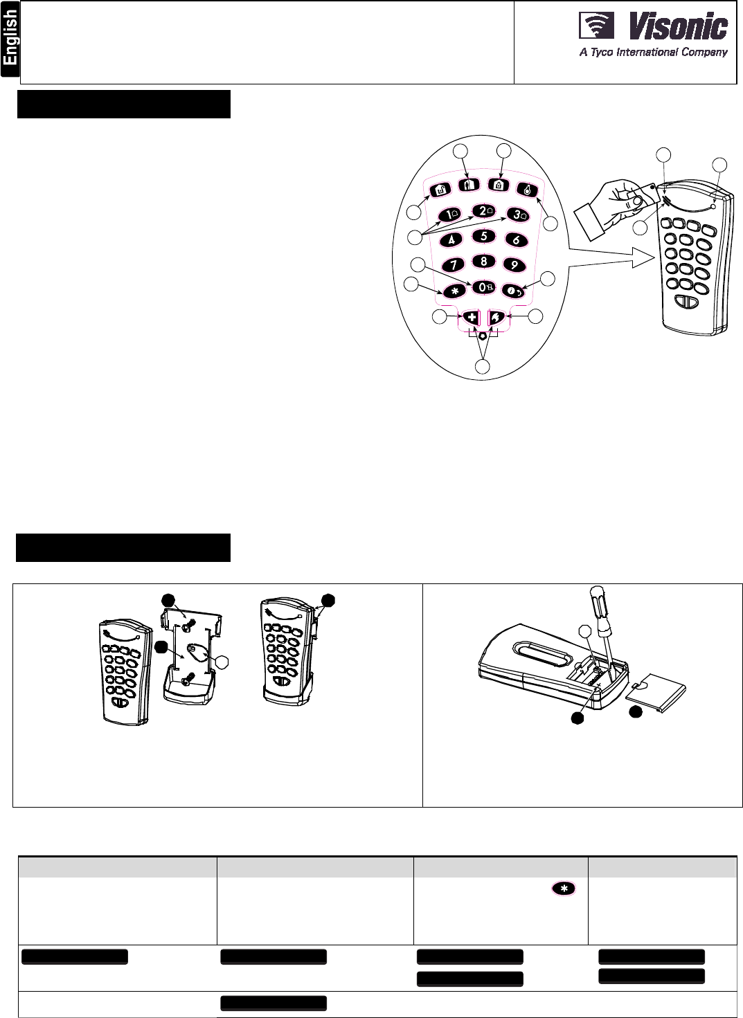
When authorization is required, for example, to arm or disarm the system, the user
can enter his PIN Code via the built-in numerical keypad or alternatively present a
valid proximity tag to the built-in tag reader (only with KP-141PG2) located at "N" in
Figure 1.
In addition, the KP-140 PG2/KP-141 PG2 keypad supports panels featuring
Partitions. Partitioning allows you to have up to three controllable areas; each partition
can be armed and disarmed independently regardless of the status of the other two
partitions by the same or different users (see buttons marked "E" in Figure 1).
The keypads can be wall mounted using the supplied bracket or be used as
portable units. For compliance with various international standards, the keypads
are equipped with two tamper switches that can be configured to detect when the
cover of the battery compartment is removed or when the unit is removed from its
mounting bracket.
Note: For UL Listed Product, unit is not intended to be portable.
Other features of the KP-140 PG2/KP-141 PG2 keypad include:
Status, alarm memory, trouble and Ready / Not-Ready indications.
Automatic reporting of low battery voltage.
Keypad back lighting.
Exit/entry beeps
Tag reader can also be used to enroll proximity tags into the panel.
Long-life 4-5 years battery life expectancy (for typical use), 3 VDC lithium battery.
Note: For UL Listed product, the proximity feature may only be used to arm or
disarm the system.
Note: For UL Listed product, Models KP-140 PG2 and KP-141 PG2 are for
Supplemental Use only.
B
A
C
D
E
F
G
H
IJ
K
L
M
N
A. ARM HOME H. AUX / ENROLLMENT
B. ARM AWAY I. EMERGENCY ALARM
C. DISARM J. FIRE ALARM
D. X-10 / PGM K. PANIC ALARM
E. PARTITION SELECTION L. BUZZER INDICATOR
F. ARM INSTANT M. LED INDICATOR
G. STATUS / ESCAPE N. TAG READER
Figure 1 - External View
2. INSTALLATION
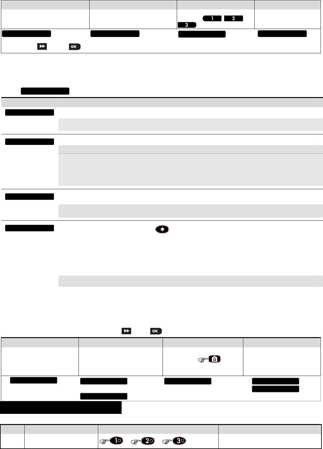
2.1 Mounting and Battery Replacement
3
A
1
2
1. Drill 2 holes in mounting surface, insert wall anchors and fasten the bracket with 2 screws.
2. Place the "Visual Indications" sticker within the frame.
3. Slide the keypad into the bracket.
A. Magnet (activates back tamper when bracket is removed from the wall).
Figure 2 - Mounting
21
A
1. Slide out the cover.
2. Replace the battery (verify proper polarity) and close the cover.
A. Battery compartment tamper switch
Caution!
Risk of explosion if battery is replaced by an incorrect type. Dispose of
used battery according to manufacturer's instructions.
Figure 3 - Battery Replacement
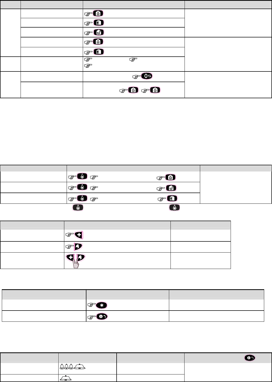
2.2. ENROLLMENT
Refer to the PowerMaster panel's Installer Guide and follow the procedure under the "02:ZONES/DEVICES" option of the Installer Menu a general description of
which is provided in the following flow chart.
Step 1 Step 2 Step 3 Step 4
Enter the Installer menu and select
“02:ZONES/DEVICES”
Select "ADD NEW DEVICE"
See Note 1 Enroll the keypad by holding the
button and release it as soon as the
yellow LED lights. Alternatively, enter the
device ID (printed on the back of the
keypad)
Select the desired keypad
Number for the new keypad
See Note 2
MODIFY DEVICES
ID No. 370-XXXX
K06:Keypad
ENTR ID:XXX-XXXX
ENROLL NOW or ADD NEW DEVICES02:ZONES/DEVICES
2 D-303015 KP-140 PG2, KP-141 PG2 Installation Instructions
Step 5 Step 6 Step 7 Step 8
Configure Location parameter Enter PARTITIONS.
See Note 3
Assign partitions to the keypad by
pressing the , and
buttons on the panel
Continue to section 2.3
means scroll and select
Notes:
1. If the keypad is already enrolled, you can configure the keypad parameters and assign partitions via the “Modify Devices” option – see Step 2.
2. The first three digits of the Device ID No. "370-XXXX" refer to KP-140 PG2. For KP-141 PG2, the first three digits of the device ID No. are "371-XXXX".
3. PARTITIONS will appear only if PARTITIONING was previously enabled in the panel (for further details, see "Partitioning" in the PowerMaster Installer Guide).
2.3. Configuring the Keypad Parameters
Enter the menu and follow the configuration instructions for the KP-140 PG2/KP-141 PG2 keypad as described in the following table.
Option Configuration Instructions
Here you determine which of the two tampers (i.e. battery compartment cover or all of the tampers) will be active.
Optional settings: Disabled (default); all tampers; Battery cover.
Note: For UL Listed product, set to “all tampers”.
Here you determine whether or not the control panel will monitor supervision messages sent by the keypad or not (see Note).
Optional settings: ON (default) or OFF.
Notes:
1. Every 5 minutes the keypad performs a communication test session with the control panel (i.e. "Supervision signal) to check
the integrity and quality of the Radio link. If the keypad does not report a supervision signal at least once within a predefined
time window, a “MISSING” trouble alert is initiated. Therefore, if you intend to take the keypad out of the protected premises you
must switch the Supervision OFF to avoid the trouble alert.
2. For UL Listed product, set to “ON”.
Here you determine whether the keypad will sound the exit and entry beeps, or not, or whether the keypad will sound the beeps only
when the system is armed AWAY and not when it is armed HOME.
Optional settings: ON; OFF (default) and OFF @ Home.
Note: For UL Listed product, the sounder cannot be used as the only annunciator for the system.
Here you select the function of the (AUX) button . Four options are offered:
Status: Control panel displays and announces (applies only to control panels that support voice) the system status.
Stop Beeps: Pressing the AUX button will cause the control panel and other devices in the system (such as keypads, sirens etc.) to
stop beeping (for example during exit or entry delays).
Skip exit delay: Pressing the AUX button will immediately stop the exit delay.
PGM: Pressing the AUX button will activate the PGM output. The functions of the PGM output is configured at the corresponding
sections of the control panel’s Installer Guide (see “OUTPUTS” menu) and User Guide (see “SCHEDULER ” menu).
Not used: No function assigned to AUX button.
Optional settings: Status (default); Stop Beeps; Skip exit delay; PGM; and Not Used.
Note: PGM not to be enabled in UL Listed Product.
2.4 Enrollment of Proximity Tags
The built-in proximity tag reader of the KP-141PG2 can be also used to enroll proximity tags into the PowerMaster panel via the keypad as described in the
corresponding section of the control panel's User or Installer Guide, or as explained in the general description provided below.
Each proximity tag corresponds to its User Code. Therefore, be sure that a corresponding User Code is programmed for each enrolled proximity tag (code "0000" is
not allowed). For example, "T02:Tag <Prox>" must be assigned to User Code 2 and "T14:Tag <Prox>" must be assigned to User Code 14. Partition authorization of
each proximity tag is identical to that of the corresponding User Code. For example, if User Code 3 is set to Partitions 1 and 3, "T03:Tag <Prox>" will also be set to
Partitions 1 and 3. Means scroll and select
Step 1 Step 2 Step 3 Step 4
Enter the Installer menu of the control
panel and select the
“02:ZONES/DEVICES”
Select the "ADD NEW DEVICES" option When "ENROLL NOW" is displayed, press
the AWAY button ( ) on the
KP-141 PG2 keypad - the AWAY button
begins to blink
Present the proximity tag to the KP-141
PG2 keypad within the timeout period.
If the enrollment is successful the display
reads "DEVICE ENROLLED" and then
shows the device details
3. USING THE KEYPAD
3.1 Arming and Disarming the System
Step Basic Arming User Actions Keypad & Panel Response
1 Select a PARTITION (1)
(when Partition is enabled) or or
The selected button lights.
K06.DEV SETTINGS K06.LOCATION K06.PARTITIONS K06:P1 P2 P3
T
01:Tag (Prox)
D
EVICE ENROLLED
E
NROLL NOW
M
ODIFY DEVICES
A
DD NEW DEVICES
0
2.ZONES/DEVICES
B
UTTON (
)
E
XIT
-
E
NTRY Beeps
S
UPERVISION
T
AMPERS
D
EVICE SETTINGS
D-303015 KP-140 PG2, KP-141 PG2 Installation Instructions 3
Step Basic Arming User Actions Keypad & Panel Response
2
Arm AWAY The selected button starts blinking and prompts you
to enter your "User Code" or present your Tag. See
step 3.
Arm HOME
Disarm (OFF)
Quick arm AWAY (2) ( 2 sec.)
The keypad's LED blinks red once to indicate
transmission of the arming command to the control
panel. The control panel's response is then
indicated on the keypad via the LED and the buzzer
– see “Panel Response to Keypad Commands”
section 3.5 below.
Quick arm HOME (2) ( 2 sec.)
3
Enter USER CODE or present
Proximity TAG. (3) (4)
[USER CODE] or [present TAG]
[DURESS CODE] (2580 by default) (5)
4
INSTANT (After arming HOME/ AWAY) (6) (8)
The keypad's LED blinks red once to indicate
transmission of the command to the control panel.
The control panel's response is then indicated on
the keypad via the LED and the buzzer – see
“Panel Response to Keypad Commands” in
section 3.5 below.
LATCHKEY (After arming AWAY) (7) (8)
Notes:
1. If Partition is disabled at the control panel, skip Step 1.
2. The Quick arm functions only if enabled at the control panel.
3. If Quick arm is selected in Step 2, skip Step 3.
4. (a) Pressing a non-valid code causes the control panel to reject the transmission.
(b) If the action is not completed while the selected arming button is blinking, the desired function will not be executed.
5. To use the Duress Code refer to the respective section in the control panel’s User Guide.
6. Press the INSTANT button within maximum 8 seconds timeout period after completing the previous step. This will delete the entry delay for the current arming session.
7. Press the AWAY button TWICE within maximum 8 seconds timeout period after completing the previous step. To use the LATCHKEY arming refer to the
respective section in the control panel’s User Guide.
8. You can perform the LATCHKEY and INSTANT functions, one after the other. The order is not important.
9. Latchkey Arming is supplemental in UL installations.
3.2 Automation
The functions of the PGM and X-10 outputs is configured at the corresponding sections of the control panel’s Installer Guide (see “OUTPUTS” menu) and User Guide
(see “SCHEDULER ” menu).
Note: Automation not to be enabled in UL Listed Product.
Output Function Actions Response
X-10 or PGM device ON [PGM 00] or [X-10 01 to 15]
The keypad's LED blinks red once to
indicate transmission of the command to
the control panel. The control panel's
response is indicated on the keypad via
the LED and the buzzer – see “Panel
Response to Keypad Commands” in
section 3.5 below.
X-10 or PGM device OFF [PGM 00] or [X-10 01 to 15]
X-10 or PGM device TOGGLE [PGM 00] or [X-10 01 to 15]
Note: Long press (more than 2 sec.) of the button initiates the X-10 function. Short press of the button initiates the PGM function.
3.3 Initiating Alarms
Alarm Actions Response
Emergency alarm ( 2 sec.)
See section 3.5.
Fire alarm ( 2 sec.)
See section 3.5.
Panic alarm ( 2 sec.) See section 3.5.
Notes:
1. For SIA CP01 compliance, the Emergency and Fire buttons are disabled. In case of Emergency or Fire, the two Panic alarm buttons should be used.
2. For UL Listed product, Emergency is for ancillary use only.
3.4 Other Functions
Function User Actions Response
AUX Function (1) See section 3.5.
STATUS indication See section 3.6
Note: The function of the AUX button is configured in section 2.3 above
3.5 Panel Response to Keypad Commands
When executing a command, the keypad's LED ("M" in Figure 1) blinks red once to indicate transmission of the command to the control panel. If the operation is
successfully completed, the green LED lights momentarily and a "happy tune" is heard. If the operation fails or cannot be completed, for example, when the
system is "not ready", the red LED lights steadily and a "sad tune" is heard. If a trouble or alarm memory condition exists in the system, or when the system is not-
ready to arm, the Status button (G in Figure 1) flashes for several seconds prompting you to press it to retrieve the status information from the control panel.
Panel Response Buzzer Indication LED Indication Problem Indication
Success: Operation is
successfully completed
Happy (success) beep Momentary GREEN If the panel is Not-Ready or if a Trouble or Alarm
Memory conditions exit, the Status button (G in Fig.1)
flashes for few seconds. To identify the reason, press
the button to retrieve the Status indication - refer to
Fail: Operation failed Sad (failure) beep Momentary RED
4 D-303015 KP-140 PG2, KP-141 PG2 Installation Instructions
Panel Response Buzzer Indication LED Indication Problem Indication
No communication: Control
panel does not respond. None None section 3.6 for further information.
3.6 Retrieving and Displaying System Status
Step Status Request User Actions Keypad & Panel Response
1 Request Status
The keypad's LED blinks red once to indicate transmission of the status
request to the control panel.
2 Look at status / /
The panel's status is indicated on the keypad via the LED and the Arming
Keys and Partition Keys – see below
Arming Status
The system Arming Status is indicated via the respective arming/disarming buttons' LED that light for several seconds. For example, if the system is
armed AWAY, the button will light and if the system is disarmed, the button will also light.
If Partition is enabled, the arming Status of the first partition is displayed concurrently with the corresponding first partition button LED , then the second
partition Status is displayed concurrently with the second partition button LED and then the third partition Status is similarly displayed.
Indication of Ready/Not Ready & Trouble Status
The Ready/Not Ready, Alarm Memory and Trouble indications are provided via the keypad LED (see "M" in Figure 1) as follows:
LED Indication [1] System Status [2] What it Means
Green System READY You can arm the system
Red System NOT- READY One of the zones is not secured. You can not arm the system before the zone is secured or bypassed. [3]
Yellow Trouble or Alarm Memory There was an alarm or there is trouble situation that need to be reviewed and cleared. [3]
Yellow blinking Keypad Low-Battery The battery of the keypad must be replaced as shown in section 2.1.
[1] The LED indication is displayed after the first red blink indicating the status request.
[2] If there is more than one status indication, the LED will display them consecutively.
[3] See respective sections in the control panel's User and Installer's Guides.
APPENDIX A: SPECIFICATIONS
Frequency Band (MHz) Europe and rest of world: 433-434, 868-869 USA: 912-919**
**Note: For UL Listed product, enable this frequency band.
Operating Temperature 0C to 49C (32F to 120F)
Dimensions (LxWxD) 127x70x24mm (5 x 2-3/4 x 31/32 in)
Communication Protocol PowerG Relative humidity 93%
Battery type
Battery Life Expectancy
3V, CR123A type. (GP)
4-5 years* (for typical use).
Weight (including
battery)
107g (3.4 oz)
Low Battery Threshold 2.1 V Color White
* 3 years+, if used with a proximity tag
APPENDIX B: COMPLIANCE WITH STANDARDS
Compliance with Standards
Europe: EN 300220-1, EN 50130-4, EN 50131-1 Grade 2 Class II, EN 50131-3, EN 301489.
The KP-140 and KP-141 PG2 are compatible with the RTTE requirements - Directive 1999/5/EC of the European Parliament and of the Council of 9 March 1999 and
EN50131-1 Grade 2 Class II.
TO14/Belgium certification by the Dutch testing and certification body Telefication BV to the following standards :
EN 50131-3, EN 50131-6, EN 50131-5-3, EN 50130-4, and EN 50130-5.
Telefication BV has certified only the 868 MHz variant of this product.
USA: CFR 47 part 15. Canada: RSS 210. RFID Tags: ISO-18000-2 (125 kHz)
UK: This product is suitable for use in systems installed to conform to PD6662:2010 at Grade 2 and environmental class 2. DD243 and BS8243
The Power G peripheral devices have two- way communication functionality, providing additional benefits as described in the technical brochure. This functionality
has not been tested to comply with the respective technical requirements and should therefore be considered outside the scope of the product’s certification.
EN 50131-1 Security Grade According to EN 50131-1:2006 and A1:2009, this equipment can be applied in installed systems up to and including Security Grade 2.
EN 50131-1 Environmental Class Class II
This device complies with FCC Rules Part 15 and with Industry Canada licence-exempt RSS standard(s).
This equipment complies with FCC and IC RF radiation exposure limits set forth for an uncontrolled environment.
RFID Tags: ISO-18000-2 (125 kHz)
Operation is subject to two conditions: (1) This device may not cause harmful interference, and (2) this device
must accept any interference that may be received or that may cause undesired operation.
The digital circuit of this device has been tested and found to comply with the limits for a Class B digital device,
pursuant to Part 15 of the FCC Rules. These limits are designed to provide reasonable protection against harmful
interference in residential installations. This equipment generates, uses and can radiate radio frequency energy
and, if not installed and used in accordance with the instructions, may cause harmful interference to radio and
television reception. However, there is no guarantee that interference will not occur in a particular installation. If this
device does cause such interference, which can be verified by turning the device off and on, the user is encouraged
to eliminate the interference by one or more of the following measures:
– Re-orient or re-locate the receiving antenna.
– Increase the distance between the device and the receiver.
– Connect the device to an outlet on a circuit different from the one which supplies power to the receiver.
– Consult the dealer or an experienced radio/TV technician.
Changes or modifications not expressly approved by Visonic Ltd. could void the user's authority to operate the
equipment.
WARNING! To comply with FCC and IC RF exposure compliance requirements,
the device should be located at a distance of at least 20 cm from all persons
during normal operation. The antennas used for this product must not be co-
located or operated in conjunction with any other antenna or transmitter.
This device complies with FCC Rules Part 15 and with Industry Canada
license-exempt RSS standard(s). Operation is subject to two conditions: (1)
This device may not cause harmful interference, and (2) this device must
accept any interference that may be received or that may cause undesired
operation.
Le présent appareil est conforme aux CNR d'Industrie Canada applicables
aux appareils radio exempts de licence. L'exploitation est autorisée aux
deux conditions suivantes : (1) l'appareil ne doit pas produire de brouillage,
et (2) l'utilisateur de l'appareil doit accepter tout brouillage radioélectrique
subi, même si le brouillage est susceptible d'en compromettre le
fonctionnement.
W.E.E.E. Product Recycling Declaration
For information regarding the recycling of this product you must contact the company from which you orignially purchased it. If you are discarding this product and not
returning it for repair then you must ensure that it is returned as identified by your supplier. This product is not to be thrown away with everyday waste.
Directive 2002/96/EC Waste Electrical and Electronic Equipment.
The technical documentation as required by the European Conformity Assessment procedure is kept at:
UNIT 6 MADINGLEY COURT CHIPPENHAM DRIVE KINGSTON MILTON KEYNES MK10 0BZ. TEL: (0845) 0755800 FAX: (0845) 0755801
EMAIL: info@visonic.com
INTERNET: www.visonic.com
VISONIC LTD. 2013 D 303015 KP-140 PG2/KP-141 PG2
(
Rev 3, 01/13
)
Please refer to se
p
arate Warrant
y
statement