Visonic MC302ELPG2 MAGNETIC CONTACT DEVICE WITH HARD-WIRED INPUT User Manual D 304537 MC 302EL PG2 Rev 0
Visonic Ltd. MAGNETIC CONTACT DEVICE WITH HARD-WIRED INPUT D 304537 MC 302EL PG2 Rev 0
Visonic >
User Manual
D-304537 MC-302EL PG2 Installation Instructions 1
MC-302EL PG2
Two-way Wireless Magnetic Contact Device with
Hard-wired Input
Installation Instructions
1. INTRODUCTION
The MC-302EL PG2 is a two-way wireless PowerG magnetic contact device that is compatible with
PowerMaster control panels, version X and above. The device includes a built-in reed switch (that
opens upon removal of a magnet placed near it) and an auxiliary hard-wired input, programmable as
either N.O., N.C. or E.O.L., for use with additional sensors – pushbuttons detectors, door contacts,
etc.
The MC-302EL PG2 can be configured through the PowerMaster control panel to allow the installer to
disable the magnet-operated reed switch if only the auxiliary input is needed. The reed switch and the
auxiliary input behave as separate transmitters, although they trigger the same RF transmitter. The
MC-302EL PG2 sends the parameters of the specific alarm to the control panel using PowerG two-
way communications protocol.
The MC-302EL PG2 tamper switch is activated when the cover is removed.
A periodic supervision message is transmitted automatically. The control panel is thus informed, at
regular intervals, of the unit’s active participation in the system.
An LED lights whenever alarm or tamper events are reported. The LED does not light while a
supervision message is being transmitted.
Operating power is obtained from an on-board 3 V Lithium battery. When the battery voltage is low, a
“low battery” message is sent to the receiver.
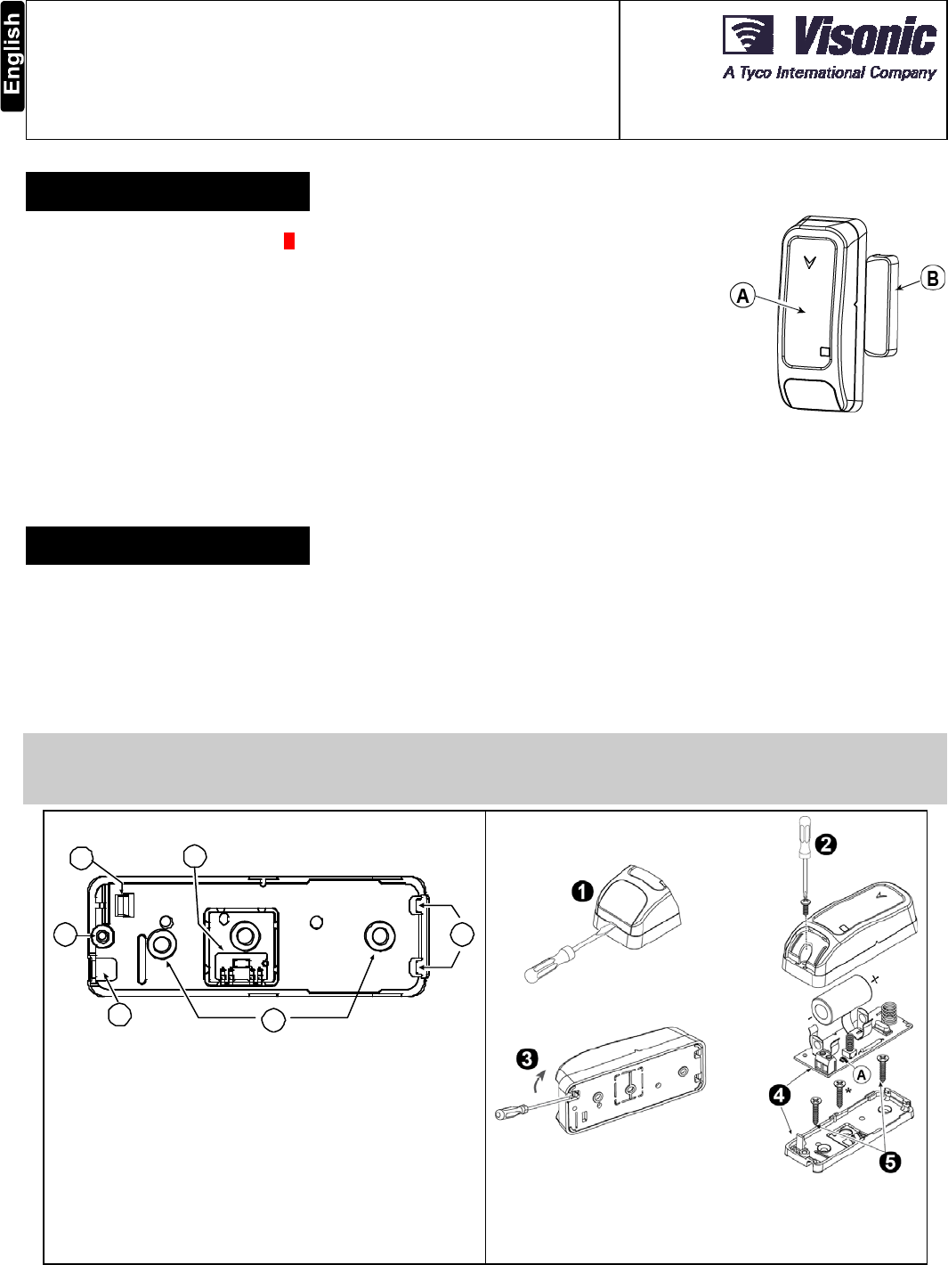
A. Transmission LED
B. Magnet
Figure 1: External View
2. INSTALLATION
2.1 Mounting (Fig. 3a and 3b)
It is highly recommended to attach the transmitter to the top of the door/window on the fixed frame and the magnet to the movable part
(door or window). Make sure that the magnet is located not more than 6 mm (0.25 in.) from the transmitter’s marked side.
Note: Once the cover is removed, a tamper message is transmitted to the receiver. Subsequent removal of the battery prevents
transmission of "TAMPER RESTORE", leaving the receiver in permanent alert. To avoid this, press the tamper switch while you remove
the battery.
Caution!
Risk of explosion if battery is replaced by an incorrect type. Dispose of used battery according to manufacturer's instructions.
Attention! The unit has a back tamper switch (optional) under the PCB. As long as the PCB is seated firmly within the base, the switch
lever will be pressed against a special break-away base segment that is loosely connected to the base (Figures 2 and 3a). Be sure to
fasten the break-away segment to the wall. If the detector unit is forcibly removed from the wall, this segment will break away from the
base, causing the tamper switch to open.
B
A
C
D
E
F
A. Flexible Retainer
B. Break-away base segment (for Back Tamper)
C. P.C. board edge supports
D. Mounting holes
E. Wiring inlet
F. Plastic standoff for case closure screw
Figure 2. Base with P.C. Board Removed
Figure 3a. Mounting
Note: 868 MHz device is illustrated in the above example. The
same mounting procedure should be performed for 433 MHz and
915 MHz devices.
* This screw is used for back tamper only.
2 D-304537 MC-302EL PG2 Installation Instructions
WARNING! To comply with FCC and IC RF exposure
compliance requirements, the magnet contact device should be
located in a distance of at least 20 cm from all persons during
normal operation. The antennas used for this product must not
be co-located or operated in conjunction with any other antenna
or transmitter.
1. Insert a flat-edged screwdriver into
the slot and push upward to
remove cover.
2. Remove screw
3. Separate base from cover.
4. Flex catch and remove P.C. board
5. Mark & drill 2 holes in mounting
surface.
Fasten base with 2 countersunk
screws.
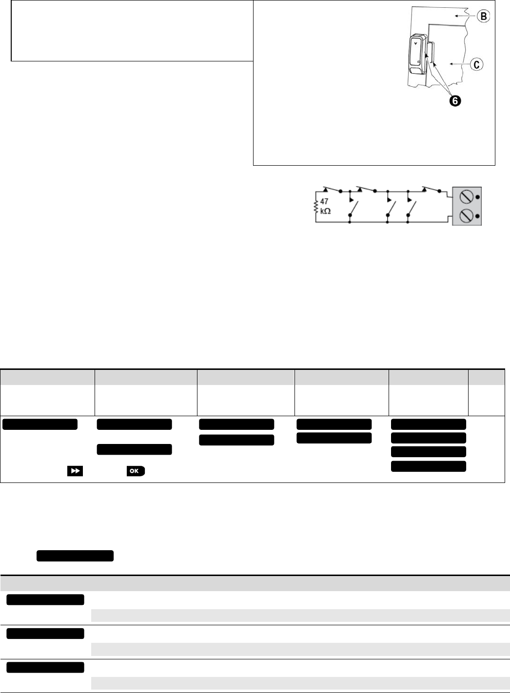
6. Mount the magnet near its location
mark with 2 screws
A. Enroll button
B. Fixed frame
C. Moving part
Figure 3b. Mounting
2.2 Auxiliary Input Wiring (Fig. 4)
A. Connect the auxiliary sensor contacts across the MC-302EL PG2
auxiliary input terminals.
B. If the auxiliary input of the MC-302EL PG2is defined as a Normally
Closed (N.C.) type, series connected N.C. sensor contacts must be
used exclusively. An E.O.L. resistor will not be required.
Figure 4. E.O.L. Wiring Example
C. If the auxiliary input of the MC-302EL PG2is defined as a Normally Open (N.O.) type, parallel connected N.O. sensor contacts must
be used exclusively. An E.O.L. resistor will not be required.
D. For E.O.L. supervision:
Normally Closed (N.C.) sensor contacts can be used, as shown in Figure 4. A 47k E.O.L. resistor must be wired at the far end of the
zone loop.
Note: For UL installations, the device connected to the initiating circuit must be located in the same room as the transmitter.
The drawing below illustrates a N.O. and N.C. alarm circuit with E.O.L. resistor.
Note: An alarm message is transmitted once the loop is opened or short circuited.
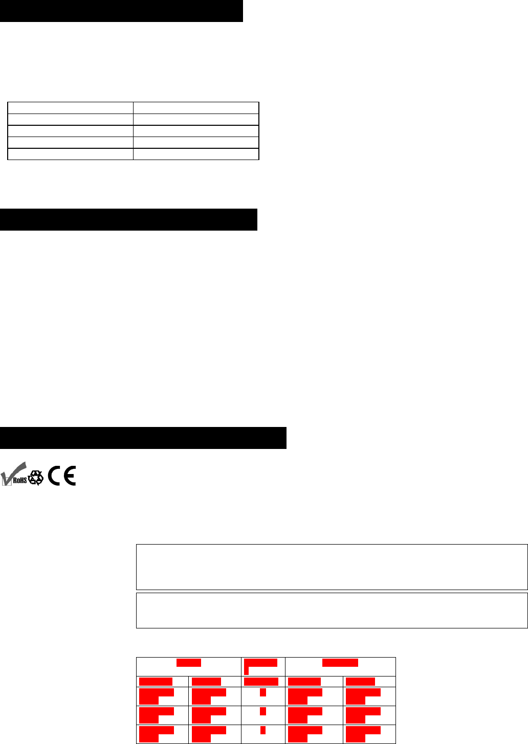
2.3. Enrollment
Refer to the PowerMaster panel's Installer Guide and follow the procedure under the "02:ZONES/DEVICES" option of the Installer Menu.
A general description of the procedure is provided in the following flow chart.
Step 1 Step 2 Step 3 Step 4 Step 5 Step 6
Enter the Installer menu
and select
“02:ZONES/DEVICES”
Select "ADD NEW
DEVICE" Option
See Note [1]
Enroll the device or Enter
the device ID Select the desired Zone
Number Configure Location,
Zone Type &
Chime Parameters
Configure
the
Magnet
means scroll and select See Note
[2]
Notes:
[1] If the magnetic contact device is already enrolled you can configure the magnetic contact device parameters via the “Modify Devices” option
– see Step 2.
[2] Select the "Device Settings" option and refer to section 2.3 to configure the magnetic contact device parameters.
2.4. Configuring the Magnetic Contact Device Parameters
Enter the menu and follow the configuration instructions for the MC-302EL PG2 magnetic contact device as described in
the following table.
Option Configuration Instructions
Determine whether or not the alarm LED indication will be activated.
Optional settings: ON (default) or OFF.
Determine whether to enable or disable the internal reed switch.
Optional settings: Enabled (default) or Disabled.
Define the external input according to the installer's requirements.
Optional settings: Disabled (default), EOL-End Of Line, Normally Open or Normally Closed.
Input #1
Reed Switch #1
Alarm LED
DEVICE SETTINGS
Z06.DEV SETTINGS
Z06.SET CHIME
Z06.ZONE TYPE
Z06.LOCATION
ID No. 104-XXXX
Z06:Contact Sens
ENTR ID:XXX-XXXX
ENROLL NOW or
MODIFY DEVICES
ADD NEW DEVICES
02.ZONES/DEVICES
D-304537 MC-302EL PG2 Installation Instructions 3
3. LOCAL DIAGNOSTICS TEST
Before testing, separate the base from the cover (see Fig. 3a).
A. Press the tamper switch once and release it.
B. Put back the cover to return the tamper switch to its normal (undisturbed) position, and then secure the front cover to the base with
the case closure screw.
C. Momentarily open the door or window and verify the red LED blinks, indicating detection.
D. After 2 seconds the LED blinks 3 times.
The following table indicates received signal strength indication.
LED response Reception
Green LED blinks Strong
Orange LED blinks Good
Red LED blinks Poor
No blinks No communication
IMPORTANT! Reliable reception must be assured. Therefore, "poor" signal strength is not acceptable. If you receive a "poor" signal from
the device, re-locate it and re-test until a "good" or "strong" signal strength is received.
Note: For detailed Diagnostics Test instructions refer to the control panel Installer Guide.
4. MISCELLANEOUS COMMENTS
Visonic Ltd. wireless systems are very reliable and are tested to high standards. However, due to low transmitting power and limited
range (required by FCC and other regulatory authorities), there are some limitations to be considered:
A. Receivers may be blocked by radio signals occurring on or near their operating frequencies, regardless of the digital code used.
B. A receiver responds only to one transmitted signal at a time.
C. Wireless devices should be tested regularly to determine whether there are sources of interference and to protect against faults.
The user is cautioned that changes or modifications to the unit, not expressly approved by Visonic Ltd., could void the user’s
FCC or other authority to operate the equipment.
The digital circuitry of this device has been tested and found to comply with the limits for a Class B digital device, pursuant to Part 15 of
the FCC Rules. These limits are designed to provide reasonable protection against harmful interference in residential installations. This
equipment generates, uses and can radiate radio frequency energy and, if not installed and used in accordance with the instructions,
may cause harmful interference to radio and television reception. However, there is no guarantee that interference will not occur in a
particular installation. If this device does cause such interference, which can be verified by turning the device off and on, the user is
encouraged to eliminate the interference by one or more of the following measures:
– Re-orient or re-locate the receiving antenna.
– Increase the distance between the device and the receiver.
– Connect the device to an outlet on a circuit different from the one which supplies power to the receiver.
– Consult the dealer or an experienced radio/TV technician
5. COMPLIANCE WITH STANDARDS
Compliance with Standards
Europe: EN 301 489-3, EN 50130-4:( 95) & A1 : (98) & A2: (03), EN 300 220-2, EN 60950-1,
EN 50130-5, EN 50131-1, EN 50131-6, , EN 50131-2-6: 2008.
The MC-302EL PG2 is compatible with the RTTE requirements - Directive 1999/5/EC of the European
Parliament and of the Council of 9 March 1999 and EN50131-1 Grade 2 Class II.
EN 50131-2-6, EN 50131-6, EN 50131-5-3, EN 50130-4, and EN 50130-5.
UK: This product is suitable for use in systems installed to conform to PD6662:2010 at Grade 2 and
environmental class 2. DD243 and BS8243
USA: CFR 47 part 15 (FCC)
Canada: RSS 210
This device complies with Part 15 of the FCC Rules and with Industry Canada license-exempt RSS
standard(s). Operation is subject to the following two conditions: (1) This device may not cause
harmful interference, and (2) this device must accept any interference received, including interference
that may cause undesired operation.
This device complies with the essential requirements and provisions of Directive 1999/5/EC of the
European Parliament and of the Council of 9 March 1999 on radio and telecommunications
terminal equipment.
The Power G peripheral devices have two- way communication functionality, providing additional benefits as described in
the technical brochure. This functionality has not been tested to comply with the respective technical requirements and
should therefore be considered outside the scope of the product’s certification.
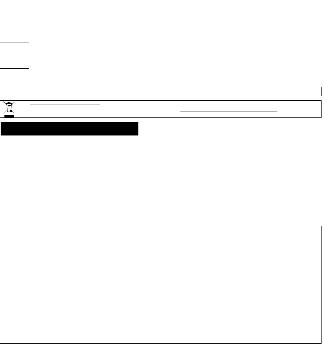
Wood Support
s Soft Iron
Opening Closing Direction Opening Closing
20mm+/-
5mm 14mm+/-
6mm X15mm+/-
5mm 14mm+/-
5mm
14mm+/-
5mm 15mm+/-
5mm Y15mm+/-
5mm 14mm+/-
5mm
25mm+/-
5mm 24mm+/-
5mm Z25mm+/-
5mm 24mm+/-
5mm
4 D-304537 MC-302EL PG2 Installation Instructions
EN 50131-1 Security Grade According to EN 50131-1:2006 and A1:2009, this equipment can be applied in installed systems up to
and includin
g
Securit
y
Grade 2.
EN 50131-1 Environmental
Class Class II
FCC Compliance Statement
The digital circuitry of this device has been tested and found to comply with the limits for a Class B digital device, pursuant to Part 15 of
the FCC Rules. These limits are designed to provide reasonable protection against harmful interference in residential installations. This
equipment generates, uses and can radiate radio frequency energy and, if not installed and used in accordance with the instructions,
may cause harmful interference to radio and television reception. However, there is no guarantee that interference will not occur in a
particular installation. If this device does cause such interference, which can be verified by turning the device off and on, the user is
encouraged to eliminate the interference by one or more of the following measures:
– Re-orient or re-locate the receiving antenna.
– Increase the distance between the device and the receiver.
– Connect the device to an outlet on a circuit different from the one which supplies power to the receiver.
– Consult the dealer or an experienced radio/TV technician
IC statement:
This device complies with Part 15 of the FCC Rules and with Industry Canada license-exempt RSS standard(s). Operation is subject to the
following two conditions: (1) this device may not cause interference, and (2) this device must accept any interference, including interference that
may cause undesired operation of the device.
Le present appareil est conforme aux CNR d'Industrie Canada applicables aux appareils radio exempts de licence. L'exploitation est
autorisee aux deux conditions suivantes :(1) l'appareil ne doit pas produire de brouillage, et (2) l'utilisateur de l'appareil doit accepter tout
brouillage radioelectrique subi, meme si le brouillage est susceptible d'en compromettre le fonctionnement.
WARNING!
To comply with FCC and IC RF exposure compliance requirements, the device should be located at a distance of at least 20 cm from all
persons during normal operation. The antennas used for this product must not be co-located or operated in conjunction with any other
antenna or transmitter.
WARNING!
The user is cautioned that changes or modifications to the unit, not expressly approved by Visonic Ltd., could void the user’s FCC or
other authority to operate the equipment.
The technical documentation as required by the European Conformity Assessment procedure is kept at:
UNIT 6 MADINGLEY COURT CHIPPENHAM DRIVE KINGSTON MILTON KEYNES MK10 0BZ. Telephone number: 0870 7300800, Fax number: 0870 7300801
W.E.E.E. Product Recycling Declaration
For information regarding the recycling of this product you must contact the company from which you orignially purchased it. If you are discarding this product and not
returning it for repair then you must ensure that it is returned as identified by your supplier. This product is not to be thrown away with everyday waste.
Directive 2002/96/EC Waste Electrical and Electronic Equipment.
APPENDIX: SPECIFICATIONS
Frequenc
y
Band
(
MHz
)
Europe and rest of world: 433-434, 868-869 USA: 912-919
Communication Protocol PowerG
Alarm Input One internal
Supe
r
vision Si
g
nalin
g
at 4-min. intervals
Tamper Alert Reported when a tamper event occurs
Power Suppl
y
T
y
pe C
Batter
y
t
y
pe 3 V Lithium CR-123 t
y
pe batter
y
, Panasonic, San
y
o or GP onl
y
.
Batter
y
Life Expectanc
y
8
y
ears
(
for t
y
pical use
)
Battery Supervision Automatic transmission of battery condition data as part of periodic status report and immediately upon
low batter
y
condition detection
Operatin
g
Temperature 0C to 49C
(
32F to 120F
)
Humidity Average relative humidity of approximate 75% non-condensing. For 30 days per year relative
humidit
y
ma
y
var
y
between 85 % and 95 % non-condensin
g
Dimensions
(
LxWxD
)
81 x 34 x 25 mm
(
3-3/16 x 1-1/4 x 1 in.
)
Wei
g
ht
(
includin
g
batter
y)
53
g
(
1.9 oz
)
WARRANTY
Visonic Limited (the “Manufacturer") warrants this product only (the "Product") to the original purchaser only (the
“Purchaser”) against defective workmanship and materials under normal use of the Product for a period of twelve
(12) months from the date of shipment by the Manufacturer.
This Warranty is absolutely conditional upon the Product having been properly installed, maintained and operated
under conditions of normal use in accordance with the Manufacturers recommended installation and operation
instructions. Products which have become defective for any other reason, according to the Manufacturers
discretion, such as improper installation, failure to follow recommended installation and operational instructions,
neglect, willful damage, misuse or vandalism, accidental damage, alteration or tampering, or repair by anyone
other than the manufacturer, are not covered by this Warranty.
The Manufacturer does not represent that this Product may not be compromised and/or circumvented or that the
Product will prevent any death and/or personal injury and/or damage to property resulting from burglary, robbery,
fire or otherwise, or that the Product will in all cases provide adequate warning or protection. The Product,
properly installed and maintained, only reduces the risk of such events without warning and it is not a guarantee
or insurance that such events will not occur.
THIS WARRANTY IS EXCLUSIVE AND EXPRESSLY IN LIEU OF ALL OTHER WARRANTIES, OBLIGATIONS
OR LIABILITIES, WHETHER WRITTEN, ORAL, EXPRESS OR IMPLIED, INCLUDING ANY WARRANTY OF
MERCHANTABILITY OR FITNESS FOR A PARTICULAR PURPOSE, OR OTHERWISE. IN NO CASE SHALL
THE MANUFACTURER BE LIABLE TO ANYONE FOR ANY CONSEQUENTIAL OR INCIDENTAL DAMAGES
FOR BREACH OF THIS WARRANTY OR ANY OTHER WARRANTIES WHATSOEVER, AS AFORESAID.
THE MANUFACTURER SHALL IN NO EVENT BE LIABLE FOR ANY SPECIAL, INDIRECT, INCIDENTAL,
CONSEQUENTIAL OR PUNITIVE DAMAGES OR FOR LOSS, DAMAGE, OR EXPENSE, INCLUDING LOSS
OF USE, PROFITS, REVENUE, OR GOODWILL, DIRECTLY OR INDIRECTLY ARISING FROM
PURCHASER’S USE OR INABILITY TO USE THE PRODUCT, OR FOR LOSS OR DESTRUCTION OF
OTHER PROPERTY OR FROM ANY OTHER CAUSE, EVEN IF MANUFACTURER HAS BEEN ADVISED OF
THE POSSIBILITY OF SUCH DAMAGE.
THE MANUFACTURER SHALL HAVE NO LIABILITY FOR ANY DEATH, PERSONAL AND/OR BODILY
INJURY AND/OR DAMAGE TO PROPERTY OR OTHER LOSS WHETHER DIRECT, INDIRECT, INCIDENTAL,
CONSEQUENTIAL OR OTHERWISE, BASED ON A CLAIM THAT THE PRODUCT FAILED TO FUNCTION.
However, if the Manufacturer is held liable, whether directly or indirectly, for any loss or damage arising under this
limited warranty, THE MANUFACTURER'S MAXIMUM LIABILITY (IF ANY) SHALL NOT IN ANY CASE
EXCEED THE PURCHASE PRICE OF THE PRODUCT, which shall be fixed as liquidated damages and not as a
penalty, and shall be the complete and exclusive remedy against the Manufacturer.
When accepting the delivery of the Product, the Purchaser agrees to the said conditions of sale and warranty and
he recognizes having been informed of.
Some jurisdictions do not allow the exclusion or limitation of incidental or consequential damages, so these
limitations may not apply under certain circumstances.
The Manufacturer shall be under no liability whatsoever arising out of the corruption and/or malfunctioning of any
telecommunication or electronic equipment or any programs.
The Manufacturers obligations under this Warranty are limited solely to repair and/or replace at the
Manufacturer’s discretion any Product or part thereof that may prove defective. Any repair and/or replacement
shall not extend the original Warranty period. The Manufacturer shall not be responsible for dismantling and/or
reinstallation costs. To exercise this Warranty the Product must be returned to the Manufacturer freight pre-paid
and insured. All freight and insurance costs are the responsibility of the Purchaser and are not included in this
Warranty.
This warranty shall not be modified, varied or extended, and the Manufacturer does not authorize any person to
act on its behalf in the modification, variation or extension of this warranty. This warranty shall apply to the
Product only. All products, accessories or attachments of others used in conjunction with the Product, including
batteries, shall be covered solely by their own warranty, if any. The Manufacturer shall not be liable for any
damage or loss whatsoever, whether directly, indirectly, incidentally, consequentially or otherwise, caused by the
malfunction of the Product due to products, accessories, or attachments of others, including batteries, used in
conjunction with the Products. This Warranty is exclusive to the original Purchaser and is not assignable.
This Warranty is in addition to and does not affect your legal rights. Any provision in this warranty which is
contrary to the Law in the state or country were the Product is supplied shall not apply.
Warning: The user must follow the Manufacturer’s installation and operational instructions including testing the
Product and its whole system at least once a week and to take all necessary precautions for his/her safety and
the protection of his/her property.
1/08

D-304537 MC-302EL PG2 Installation Instructions 5
EMAIL: info@visonic.com
INTERNET: www.visonic.com
VISONIC LTD. 2013 D-304537 MC-302EL PG2 (Rev 0, 01/13)