Visonic MC312PG2 Wireless outdoor magnetic contact User Manual GB 502 PG2 Installation Instructions
Visonic Ltd. Wireless outdoor magnetic contact GB 502 PG2 Installation Instructions
UserManual.wiki
>
Visonic
>
MC312PG2 User Manual
Users Manual
Navigation menu
Upload a User Manual
Namespaces
Wiki Guide
HTML
PDF
Info
Views
User Manual
Discussion / Help
Navigation
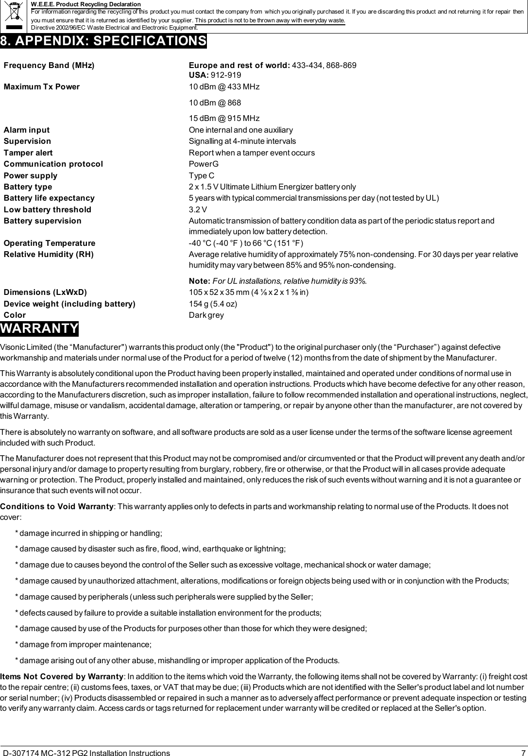
![2.4. Enrolling the MC-312 PG2Refer to the relevant control panel installer guide and follow the procedure under the “02: ZONES/DEVICES” option of the Installer Menu. A generaldescription of the procedure is provided in the following flow chart.Step 1 Step 2 Step 3 Step 4 Step 5 Step 6Enter the installermenu and select 02:ZONES / DEVICESSelect ADD NEWDEVICE. See note [1]Enroll the device orenter the device IDSelect the desiredzone numberConfigure thelocation, zone type,and chimeparametersConfigure thedetector02:ZONES DEVICES >ADD NEW DEVICES > Z06: LOCATIONZ06: ZONE TYPEENROLL NOW orENTERID: XXX-XXXX >Z06: ContactSensor ID No.107-XXXXZ06: SET CHIMEZ06: DEVSETTINGSSee section 2.7Notes:If the magnetic contact device is already enrolled you can configure the magnetic contact deviceparameters using the Modify Devices option (see step 2).Select the Device Settings option and refer to "Configuring the MC-312 PG2device parameters" below toconfigure the device parameters.To enroll the device as noted in step 3, you can power on the device, press the enrollment button, orremove the pull tab on new devices (see Fig. 8). Figure 8 - Enrollment optionsA: Enrollment tabB: Enrollment button2.5. Configuring the MC-312 PG2device parametersEnter the control panel DEVICE SETTINGS menu and follow the configuration instructions for the MC-312 PG2 magnetic contact device as describedin the Table 2.Option Configuration instructionsMagnetic sensor Determine whether to enable or disable the magnetic sensor.Optional settings: Enabled (default) or Disabled.Input #1 Define the external input according to the installer's requirements.Optional settings: Disabled (default), Normally Open,Normally Closed,End of Line, or Double End of Line.Note: DEOL support is dependent on panel software version.Anti-mask Determine whether to enable or disable the anti-masking protection.Optional settings: Enabled or Disabled (default).Note: This feature is dependent on panel software version.Table 2 - Magnetic device parametersD-307174 MC-312 PG2 Installation Instructions 3](https://usermanual.wiki/Visonic/MC312PG2/User-Guide-3955560-Page-3.png)