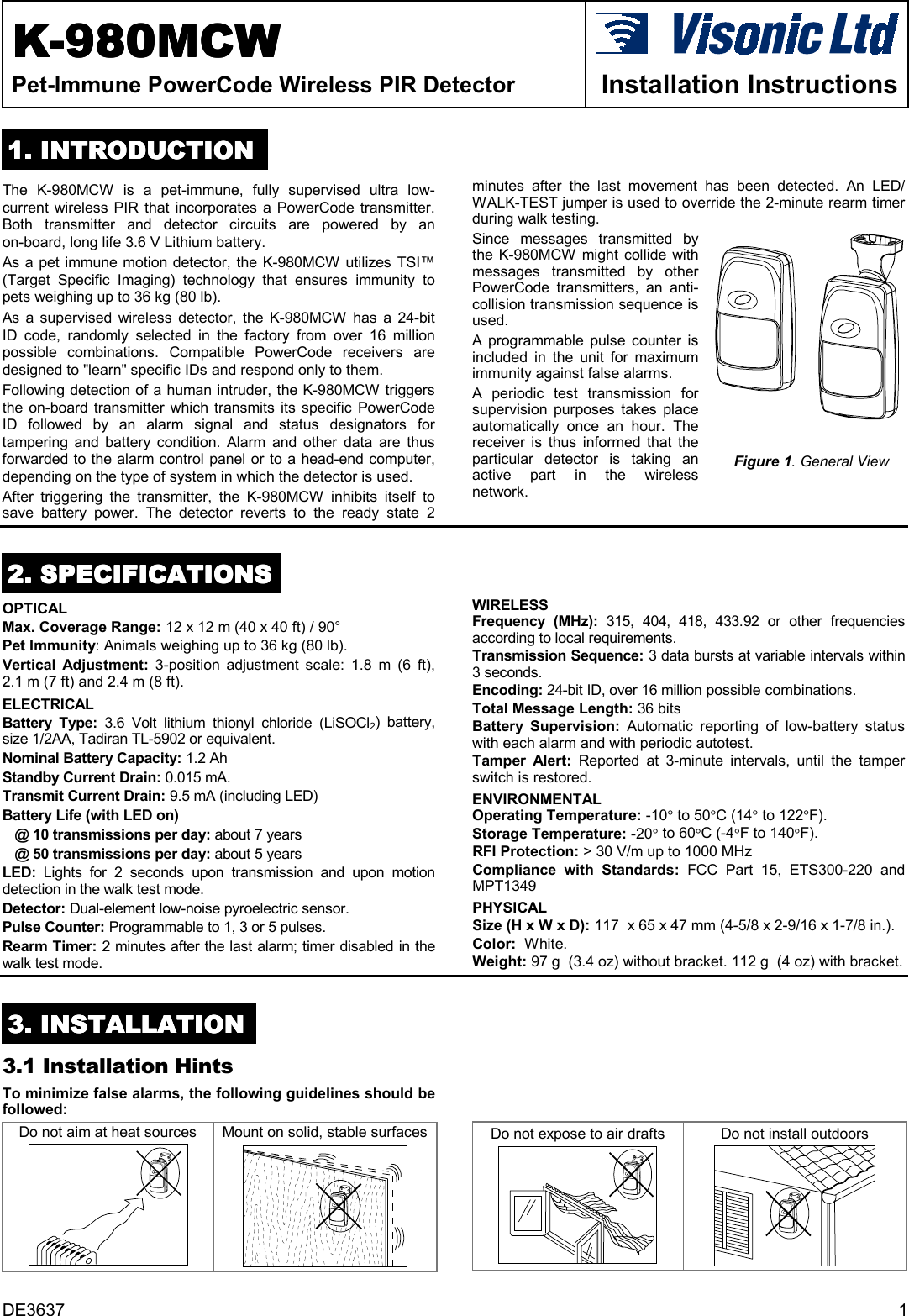
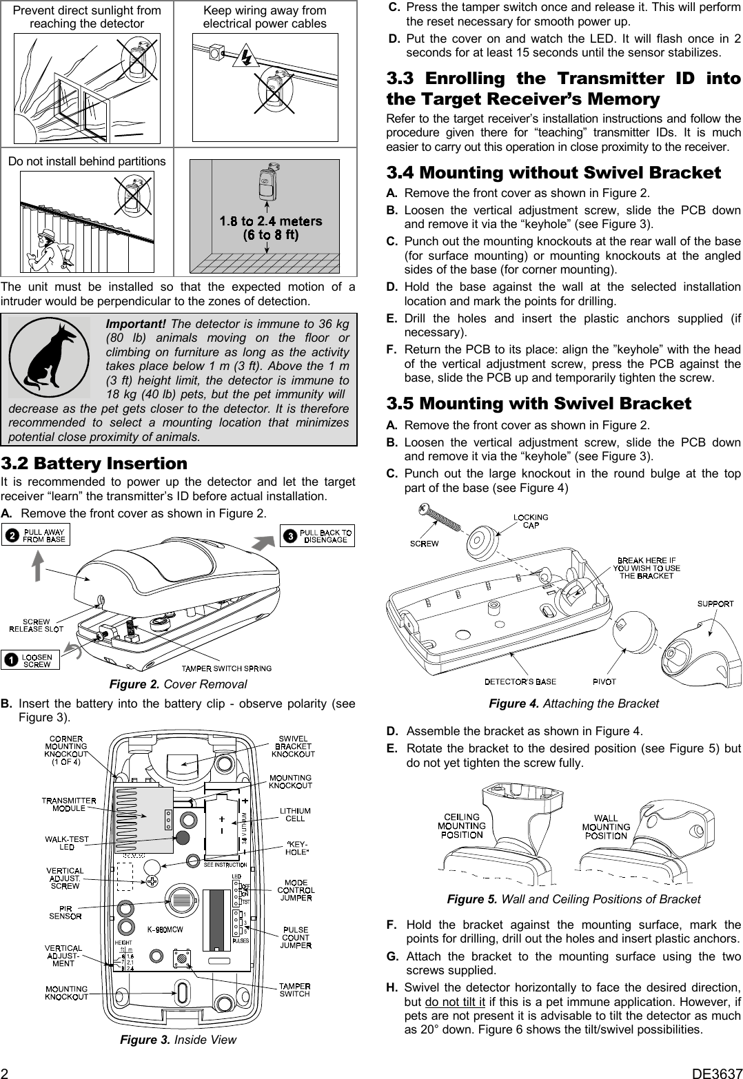
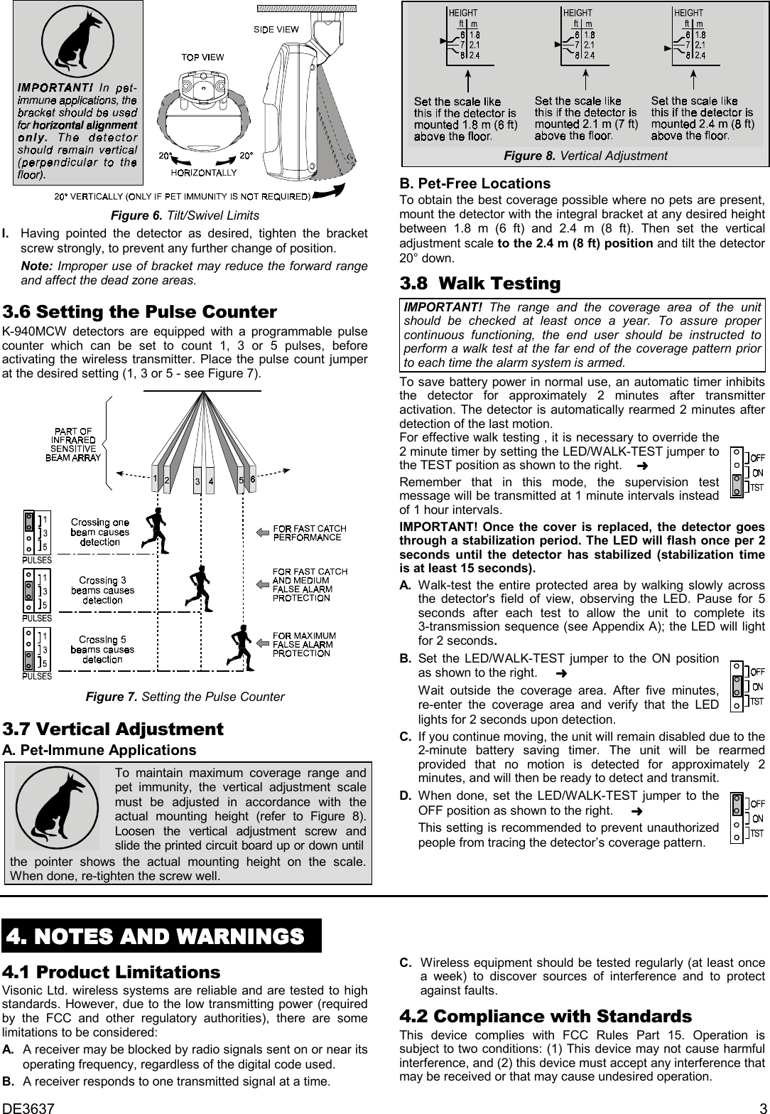
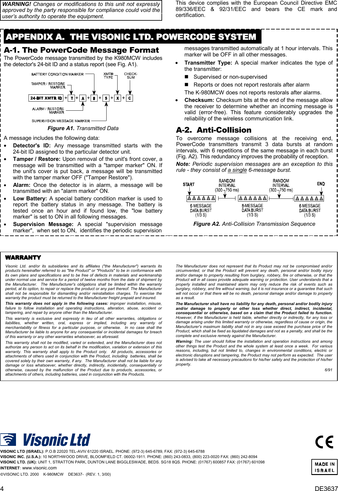
Visonic MCPIR3000 Pet-immune Powercode Wireless PIR Detector K-980 M User Manual DE3637 1

Visonic Inc. Pet-immune Powercode Wireless PIR Detector K-980 M DE3637 1

4 pages

DE3637 1KKKK-980-980-980-980MCWMCWMCWMCWPet-Immune PowerCode Wireless PIR Detector Installation Instructions1111. INTRODUCTION. INTRODUCTION. INTRODUCTION. INTRODUCTIONThe K-980MCW is a pet-immune, fully supervised ultra low-current wireless PIR that incorporates a PowerCode transmitter.Both transmitter and detector circuits are powered by anon-board, long life 3.6 V Lithium battery.As a pet immune motion detector, the K-980MCW utilizes TSI™(Target Specific Imaging) technology that ensures immunity topets weighing up to 36 kg (80 lb).  As a supervised wireless detector, the K-980MCW has a 24-bitID code, randomly selected in the factory from over 16 millionpossible combinations. Compatible PowerCode receivers aredesigned to "learn" specific IDs and respond only to them.Following detection of a human intruder, the K-980MCW triggersthe on-board transmitter which transmits its specific PowerCodeID followed by an alarm signal and status designators fortampering and battery condition. Alarm and other data are thusforwarded to the alarm control panel or to a head-end computer,depending on the type of system in which the detector is used.After triggering the transmitter, the K-980MCW inhibits itself tosave battery power. The detector reverts to the ready state 2minutes after the last movement has been detected. An LED/WALK-TEST jumper is used to override the 2-minute rearm timerduring walk testing.Since messages transmitted bythe K-980MCW might collide withmessages transmitted by otherPowerCode transmitters, an anti-collision transmission sequence isused.A programmable pulse counter isincluded in the unit for maximumimmunity against false alarms.A periodic test transmission forsupervision purposes takes placeautomatically once an hour. Thereceiver is thus informed that theparticular detector is taking anactive part in the wirelessnetwork.Figure 1. General View2222. SPECIFICATIONS. SPECIFICATIONS. SPECIFICATIONS. SPECIFICATIONSOPTICAL  Max. Coverage Range: 12 x 12 m (40 x 40 ft) / 90°Pet Immunity: Animals weighing up to 36 kg (80 lb).Vertical Adjustment: 3-position adjustment scale: 1.8 m (6 ft),2.1 m (7 ft) and 2.4 m (8 ft).ELECTRICALBattery Type: 3.6 Volt lithium thionyl chloride (LiSOCl2) battery,size 1/2AA, Tadiran TL-5902 or equivalent.Nominal Battery Capacity: 1.2 AhStandby Current Drain: 0.015 mA.Transmit Current Drain: 9.5 mA (including LED)Battery Life (with LED on)@ 10 transmissions per day: about 7 years@ 50 transmissions per day: about 5 yearsLED:  Lights for 2 seconds upon transmission and upon motiondetection in the walk test mode.Detector: Dual-element low-noise pyroelectric sensor.Pulse Counter: Programmable to 1, 3 or 5 pulses.Rearm Timer: 2 minutes after the last alarm; timer disabled in thewalk test mode.WIRELESSFrequency (MHz): 315, 404, 418, 433.92 or other frequenciesaccording to local requirements.Transmission Sequence: 3 data bursts at variable intervals within3 seconds.Encoding: 24-bit ID, over 16 million possible combinations.Total Message Length: 36 bitsBattery Supervision: Automatic reporting of low-battery statuswith each alarm and with periodic autotest.Tamper Alert: Reported at 3-minute intervals, until the tamperswitch is restored.ENVIRONMENTALOperating Temperature: -10° to 50°C (14° to 122°F).Storage Temperature: -20° to 60°C (-4°F to 140°F).RFI Protection: > 30 V/m up to 1000 MHzCompliance with Standards: FCC Part 15, ETS300-220 andMPT1349PHYSICALSize (H x W x D): 117  x 65 x 47 mm (4-5/8 x 2-9/16 x 1-7/8 in.).Color:  White.Weight: 97 g  (3.4 oz) without bracket. 112 g  (4 oz) with bracket.3333. INSTALLATION. INSTALLATION. INSTALLATION. INSTALLATION3.1 Installation HintsTo minimize false alarms, the following guidelines should befollowed:Do not aim at heat sources Mount on solid, stable surfaces Do not expose to air drafts Do not install outdoors
2DE3637Prevent direct sunlight fromreaching the detectorKeep wiring away fromelectrical power cablesDo not install behind partitionsThe unit must be installed so that the expected motion of aintruder would be perpendicular to the zones of detection.Important! The detector is immune to 36 kg(80 lb) animals moving on the floor orclimbing on furniture as long as the activitytakes place below 1 m (3 ft). Above the 1 m(3 ft) height limit, the detector is immune to18 kg (40 lb) pets, but the pet immunity will  decrease as the pet gets closer to the detector. It is thereforerecommended to select a mounting location that minimizespotential close proximity of animals.3.2 Battery InsertionIt is recommended to power up the detector and let the targetreceiver “learn” the transmitter’s ID before actual installation.  A .  Remove the front cover as shown in Figure 2.Figure 2. Cover RemovalB. Insert the battery into the battery clip - observe polarity (seeFigure 3).Figure 3. Inside View  C .  Press the tamper switch once and release it. This will performthe reset necessary for smooth power up.  D .  Put the cover on and watch the LED. It will flash once in 2seconds for at least 15 seconds until the sensor stabilizes.3.3 Enrolling the Transmitter ID intothe Target Receiver’s MemoryRefer to the target receiver’s installation instructions and follow theprocedure given there for “teaching” transmitter IDs. It is mucheasier to carry out this operation in close proximity to the receiver.3.4 Mounting without Swivel BracketA. Remove the front cover as shown in Figure 2.B. Loosen the vertical adjustment screw, slide the PCB downand remove it via the “keyhole” (see Figure 3).C. Punch out the mounting knockouts at the rear wall of the base(for surface mounting) or mounting knockouts at the angledsides of the base (for corner mounting).D. Hold the base against the wall at the selected installationlocation and mark the points for drilling.E. Drill the holes and insert the plastic anchors supplied (ifnecessary).F. Return the PCB to its place: align the ”keyhole” with the headof the vertical adjustment screw, press the PCB against thebase, slide the PCB up and temporarily tighten the screw.3.5 Mounting with Swivel BracketA. Remove the front cover as shown in Figure 2.B. Loosen the vertical adjustment screw, slide the PCB downand remove it via the “keyhole” (see Figure 3).C. Punch out the large knockout in the round bulge at the toppart of the base (see Figure 4)  Figure 4. Attaching the Bracket  D .  Assemble the bracket as shown in Figure 4.  E .  Rotate the bracket to the desired position (see Figure 5) butdo not yet tighten the screw fully.      Figure 5. Wall and Ceiling Positions of Bracket    F .  Hold the bracket against the mounting surface, mark thepoints for drilling, drill out the holes and insert plastic anchors.  G .  Attach the bracket to the mounting surface using the twoscrews supplied.H. Swivel the detector horizontally to face the desired direction,but do not tilt it if this is a pet immune application. However, ifpets are not present it is advisable to tilt the detector as muchas 20° down. Figure 6 shows the tilt/swivel possibilities.
DE3637 3Figure 6. Tilt/Swivel LimitsI. Having pointed the detector as desired, tighten the bracketscrew strongly, to prevent any further change of position.Note: Improper use of bracket may reduce the forward rangeand affect the dead zone areas.3.6 Setting the Pulse CounterK-940MCW detectors are equipped with a programmable pulsecounter which can be set to count 1, 3 or 5 pulses, beforeactivating the wireless transmitter. Place the pulse count jumperat the desired setting (1, 3 or 5 - see Figure 7).Figure 7. Setting the Pulse Counter3.7 Vertical AdjustmentA. Pet-Immune ApplicationsTo maintain maximum coverage range andpet immunity, the vertical adjustment scalemust be adjusted in accordance with theactual mounting height (refer to Figure 8).Loosen the vertical adjustment screw andslide the printed circuit board up or down untilthe pointer shows the actual mounting height on the scale.When done, re-tighten the screw well.Figure 8. Vertical AdjustmentB. Pet-Free Locations  To obtain the best coverage possible where no pets are present,mount the detector with the integral bracket at any desired heightbetween 1.8 m (6 ft) and 2.4 m (8 ft). Then set the verticaladjustment scale to the 2.4 m (8 ft) position and tilt the detector20° down.3.8  Walk TestingIMPORTANT!  The range and the coverage area of the unitshould be checked at least once a year. To assure propercontinuous functioning, the end user should be instructed toperform a walk test at the far end of the coverage pattern priorto each time the alarm system is armed.To save battery power in normal use, an automatic timer inhibitsthe detector for approximately 2 minutes after transmitteractivation. The detector is automatically rearmed 2 minutes afterdetection of the last motion.For effective walk testing , it is necessary to override the2 minute timer by setting the LED/WALK-TEST jumper tothe TEST position as shown to the right.    ➜Remember that in this mode, the supervision testmessage will be transmitted at 1 minute intervals insteadof 1 hour intervals.IMPORTANT! Once the cover is replaced, the detector goesthrough a stabilization period. The LED will flash once per 2seconds until the detector has stabilized (stabilization timeis at least 15 seconds).A. Walk-test the entire protected area by walking slowly acrossthe detector's field of view, observing the LED. Pause for 5seconds after each test to allow the unit to complete its3-transmission sequence (see Appendix A); the LED will lightfor 2 seconds.B. Set the LED/WALK-TEST jumper to the ON positionas shown to the right.     ➜Wait outside the coverage area. After five minutes,re-enter the coverage area and verify that the LEDlights for 2 seconds upon detection.  C. If you continue moving, the unit will remain disabled due to the2-minute battery saving timer. The unit will be rearmedprovided that no motion is detected for approximately 2minutes, and will then be ready to detect and transmit.D. When done, set the LED/WALK-TEST jumper to theOFF position as shown to the right.     ➜This setting is recommended to prevent unauthorizedpeople from tracing the detector’s coverage pattern.4444. NOTES AND WARNINGS. NOTES AND WARNINGS. NOTES AND WARNINGS. NOTES AND WARNINGS4.1 Product LimitationsVisonic Ltd. wireless systems are reliable and are tested to highstandards. However, due to the low transmitting power (requiredby the FCC and other regulatory authorities), there are somelimitations to be considered:  A .   A receiver may be blocked by radio signals sent on or near itsoperating frequency, regardless of the digital code used.  B .  A receiver responds to one transmitted signal at a time.  C .  Wireless equipment should be tested regularly (at least oncea week) to discover sources of interference and to protectagainst faults.4.2 Compliance with StandardsThis device complies with FCC Rules Part 15. Operation issubject to two conditions: (1) This device may not cause harmfulinterference, and (2) this device must accept any interference thatmay be received or that may cause undesired operation.
4DE3637WARNING! Changes or modifications to this unit not expresslyapproved by the party responsible for compliance could void theuser’s authority to operate the equipment.This device complies with the European Council Directive EMC89/336/EEC & 92/31/EEC and bears the CE mark andcertification.APPENDIX A.  THE VISONIC LTD. POWERCODE SYSTEMAPPENDIX A.  THE VISONIC LTD. POWERCODE SYSTEMAPPENDIX A.  THE VISONIC LTD. POWERCODE SYSTEMAPPENDIX A.  THE VISONIC LTD. POWERCODE SYSTEMA-1. The PowerCode Message FormatThe PowerCode message transmitted by the K980MCW includesthe detector's 24-bit ID and a status report (see Fig. A1).Figure A1. Transmitted DataA message includes the following data: •    Detector's ID: Any message transmitted starts with the24-bit ID assigned to the particular detector unit. •    Tamper / Restore: Upon removal of the unit's front cover, amessage will be transmitted with a "tamper marker" ON. Ifthe unit's cover is put back, a message will be transmittedwith the tamper marker OFF ("Tamper Restore"). •    Alarm: Once the detector is in alarm, a message will betransmitted with an "alarm marker" ON. •    Low Battery: A special battery condition marker is used toreport the battery status in any message. The battery istested once an hour and if found low, the "low batterymarker" is set to ON in all following messages. •    Supervision Message: A special "supervision messagemarker",  when set to ON,  identifies the periodic supervision  messages transmitted automatically at 1 hour intervals. Thismarker will be OFF in all other messages. •    Transmitter Type: A special marker indicates the type ofthe transmitter: "  Supervised or non-supervised "  Reports or does not report restorals after alarm  The K-980MCW does not reports restorals after alarms. •    Checksum: Checksum bits at the end of the message allowthe receiver to determine whether an incoming message isvalid (error-free). This feature considerably upgrades thereliability of the wireless communication link.A-2.  Anti-CollisionTo overcome message collisions at the receiving end,PowerCode transmitters transmit 3 data bursts at randomintervals, with 6 repetitions of the same message in each burst(Fig. A2). This redundancy improves the probability of reception.Note: Periodic supervision messages are an exception to thisrule - they consist of a single 6-message burst.Figure A2. Anti-Collision Transmission SequenceWARRANTYWARRANTYWARRANTYWARRANTYVisonic Ltd. and/or its subsidiaries and its affiliates ("the Manufacturer") warrants itsproducts hereinafter referred to as "the Product" or "Products" to be in conformance withits own plans and specifications and to be free of defects in materials and workmanshipunder normal use and service for a period of twelve months from the date of shipment bythe Manufacturer.  The Manufacturer's obligations shall be limited within the warrantyperiod, at its option, to repair or replace the product or any part thereof. The Manufacturershall not be responsible for dismantling and/or reinstallation charges. To exercise thewarranty the product must be returned to the Manufacturer freight prepaid and insured.This warranty does not apply in the following cases: improper installation, misuse,failure to follow installation and operating instructions, alteration, abuse, accident ortampering, and repair by anyone other than the Manufacturer.This warranty is exclusive and expressly in lieu of all other warranties, obligations orliabilities, whether written, oral, express or implied, including any warranty ofmerchantability or fitness for a particular purpose, or otherwise.  In no case shall theManufacturer be liable to anyone for any consequential or incidental damages for breachof this warranty or any other warranties whatsoever, as aforesaid.This warranty shall not be modified, varied or extended, and the Manufacturer does notauthorize any person to act on its behalf in the modification, variation or extension of thiswarranty. This warranty shall apply to the Product only.  All products, accessories orattachments of others used in conjunction with the Product, including  batteries, shall becovered solely by their own warranty, if any.  The Manufacturer shall not be liable for anydamage or loss whatsoever, whether directly, indirectly, incidentally, consequentially orotherwise, caused by the malfunction of the Product due to products, accessories, orattachments of others, including batteries, used in conjunction with the Products.The Manufacturer does not represent that its Product may not be compromised and/orcircumvented, or that the Product will prevent any death, personal and/or bodily injuryand/or damage to property resulting from burglary, robbery, fire or otherwise, or that theProduct will in all cases provide adequate warning or protection. User understands that aproperly installed and maintained alarm may only reduce the risk of events such asburglary, robbery, and fire without warning, but it is not insurance or a guarantee that suchwill not occur or that there will be no death, personal damage and/or damage to propertyas a result.The Manufacturer shall have no liability for any death, personal and/or bodily injuryand/or damage to property or other loss whether direct, indirect, incidental,consequential or otherwise, based on a claim that the Product failed to function.  However, if the Manufacturer is held liable, whether directly or indirectly, for any loss ordamage arising under this limited warranty or otherwise, regardless of cause or origin, theManufacturer's maximum liability shall not in any case exceed the purchase price of theProduct, which shall be fixed as liquidated damages and not as a penalty, and shall be thecomplete and exclusive remedy against the Manufacturer.Warning: The user should follow the installation and operation instructions and amongother things test the Product and the whole system at least once a week.  For variousreasons, including, but not limited to, changes in environmental conditions, electric orelectronic disruptions and tampering, the Product may not perform as expected.  The useris advised to take all necessary precautions for his/her safety and the protection of his/herproperty.6/91VISONIC LTD (ISRAEL): P.O.B 22020 TEL-AVIV 61220 ISRAEL. PHONE: (972-3) 645-6789, FAX: (972-3) 645-6788VISONIC INC. (U.S.A.): 10 NORTHWOOD DRIVE, BLOOMFIELD CT. 06002-1911. PHONE: (860) 243-0833, (800) 223-0020 FAX: (860) 242-8094VISONIC LTD. (UK): UNIT 1, STRATTON PARK, DUNTON LANE BIGGLESWADE, BEDS. SG18 8QS. PHONE: (01767) 600857 FAX: (01767) 601098INTERNET: www.visonic.comVISONIC LTD. 2000    K-980MCW    DE3637-  (REV. 1, 3/00)

Navigation menu