Visonic MCT237 Key fob transceiver User Manual
Visonic Inc. Key fob transceiver Users Manual
Visonic >
Users Manual
D-300280 1
MCT
MCTMCT
MCT-
--
-237
237237
237
Wireless CodeSecure™ Two-Way Keyfob Transmitter User Guide
1. INTRODUCTION
1. INTRODUCTION1. INTRODUCTION
1. INTRODUCTION
1.1 Description
The MCT-237 is a miniature CodeSecure™ 6-button keyfob
transmitter, designed for use with the PowerMax Pro unit. The
device enables the user to arm/disarm the alarm system and to
view system status.
For each PowerMax Pro control panel, a maximum of eight
MCT-237 keyfob devices may be enrolled. Operating power is
obtained from an internal 1.5 V alkaline battery. Each transmitter
is supplied with a small keyring.
Transmission is initiated by pressing any one of the six
pushbuttons. Upon pressing a specific button, the keyfob
transmits a CodeSecure™ digital sequence identifiable by the
PowerMax unit, and a 4-bit function code associated with the
button that was pressed.
The next time a button is pressed, the keyfob will transmit a digital
sequence of three transmissions that differs from the one used in
the previous transmission and the respective function code. As a
result, malicious “code grabbing” is virtually impossible.
The main features of the MCT-237 are:
• Status, alarm memory, and trouble data retrieval from PowerMax Pro.
• Visual indications by LCD icon display.
• LCD backlighting activation.
• Various audible signals sounded by the speaker in response to
specific actions.
• 1.5 Volt Alkaline battery.
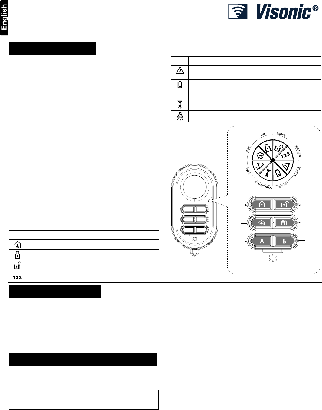
1.2 LCD Icons
The following table provides definitions for each of the eight icons
that appear on the LCD display.
Icon Definition
Lights when the system is in Arm Home mode
Lights when the system is in Arm Away mode
Lights when the system is disarmed
Partition: Not available in this version
Icon Definition
Trouble: Indicates a trouble state is detected within the
PowerMax Pro.
Low Battery: Indicates the battery must be replaced
without delay. In addition, a “low battery” report will be
transmitted with the outgoing digital message.
Communication: Indicates a communication failure
Alarm: Indicates that the alarm has been activated
PANIC
(Press both buttons
simultaneously for 2 seconds)
ARM
HOME
AUX A
DISARM
STATUS
AUX B
Figure 1. External View
2. SPECIFICATIONS
2. SPECIFICATIONS2. SPECIFICATIONS
2. SPECIFICATIONS
Frequency (MHz): 315, 433, 868.95 or according to local requirements
Modulation: ASK (ON-OFF keying)
Coding: CodeSecure
Battery: 1.5 V AAA alkaline battery, type GP or equivalent
Current Consumption: 85 mA during transmission
Battery Life Expectancy: 2 years (for typical use)
Note: If transmission is still possible despite the battery condition,
the unit will send a low battery signal to the receiver.
Control Functions: Home Arming, Away Arming, Disarming,
System Status, AUX 1 and 2
Operating Temperature: 0° to 49°C (32° to 120°F).
Dimensions: 75 x 38 x 18 mm (2-15/16 x 1-1/2 x 11/16 in.).
Weight (including battery): 36 g (1¼ oz).
Color: Black
Compliance with Standards: EN 50131-1 Grade 2, Class II
3. TESTING AND MAINTENANCE
3. TESTING AND MAINTENANCE3. TESTING AND MAINTENANCE
3. TESTING AND MAINTENANCE
3.1 Testing a New Unit
Since the keyfob transmitter is supplied with the battery already
installed, the unit is practically ready to be tested.
IMPORTANT! Before testing, "teach" the PowerMax Pro the
ID code of the keyfob, as instructed in the PowerMax Pro
Installer Guide.
A. Stand near the PowerMax Pro control panel and press the
keyfob button marked with a closed padlock icon.
B. Make sure that the control panel responds as programmed and
as stated in the PowerMax Pro Installer Guide.
C. Operate the keyfob from various locations within the area covered
by the receiver to determine "dead" locations, where transmission
is blocked by walls and large objects, or affected by structural
materials. For optimum operation, point the keyfob directly toward
the PowerMax Pro control panel.
Note: If dead/marginal zones are a problem, relocating the
PowerMax Pro control panel may improve the performance.
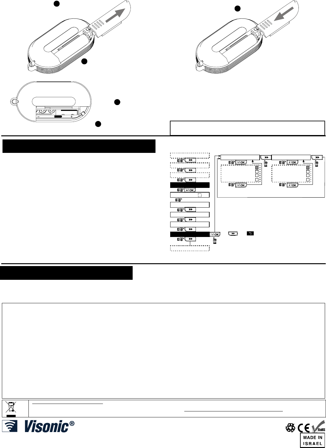
3.2 Replacing the Battery
Caution: Risk of explosion if battery is replaced by an incorrect
type. Dispose of used batteries according to the instructions.
The battery should be replaced upon receiving a low battery LCD
indication. A replacement 1.5 V AAA alkaline battery, such as GP
(or equivalent), should be used. Replace the battery as follows:
2 D-300280
2
1ON THE REVERSE SIDE
OF THE UNIT, SLIDE THE
COVER IN THE
DIRECTION SHOWN
EXTRACT THE BATTERY
FROM ITS HOLDER
Figure 2. Battery Removal
NOTE: INSERT B ATTERY WITH NEGATIVE (--)
EDGE PRESSED AGAINST THE SPRING
( ) ( )
AAA
1
2
INSERT THE
NEW B ATTERY
TEST THE UNIT BY MOMENT
A
RILY
PRESSING ONE OF THE TRANSMIT
SWITCHES. THE LCD DISPLAY
SHOULD LIGHT.
3
SLIDE THE
COVER BACK ON
IN THE DIRECTION
SHOWN
Figure 3. Inserting New Battery
3.3 Cleaning
The transmitter may get dirty if touched with greasy fingers.
Clean it only with a soft cloth or sponge moistened lightly with a
mixture of water and mild detergent, and wipe it dry immediately.
The use of abrasives of any kind is strictly forbidden. Also
never use solvents such as kerosene, acetone or thinner.
4. DEFINING KEYFOB OPTIONS
4. DEFINING KEYFOB OPTIONS4. DEFINING KEYFOB OPTIONS
4. DEFINING KEYFOB OPTIONS
Note: To enroll the MCT-237, refer to the PowerMax Pro User
Guide section 7 (User Settings) – Enrolling Keyfob Transmitters.
Here you select the function of the two AUX buttons on the
transmitter. Four options are offered for each AUX button:
Status: Pressing the AUX button will cause the control panel’s
voice module to announce the system status.
Instant: Pressing the AUX button while the exit delay is in
progress will cause the system to arm “instant” (the entry delay is
canceled).
Skip exit delay: Pressing the AUX button will immediately cause
the system to arm.
PGM / X-10: Pressing the AUX button will activate the PGM
output or X-10 units.
Proceed as shown in the following flow chart.
READY 00:00
USER SETTINGS
NORMAL MODE
ENTER CODE
1. NEW INSTL CODE
2. ENROLLING
3. DEFINE ZONES
[installer code]
INSTALLER MODE
4. DEFINE PANEL
<OK> TO EXIT
Note: The currently saved
options are displayed with
dark box at the right side of
the display. To review the
options, repeatedly click
or on the
PowerMax Pro control
panel until the desired
option is displayed. Then,
click OK (a dark box will be
displayed at the right side).
17: AUX BUTTON A
status
instant
PGM / X-10
skip exit delay
18: AUX B 2-W-KF
status
instant
PGM / X-10
skip exit delay
Figure 4: Performing PowerMax Pro Audio Functions
5. GENERAL COMMENTS
5. GENERAL COMMENTS5. GENERAL COMMENTS
5. GENERAL COMMENTS
This device complies with Part 15 of the FCC Rules. Operation is subject
to the following two conditions: (1) this device may not cause harmful
interference, and (2) this device must accept any interference received,
including interference that may cause undesired operation.
Any changes or modification not expressly approved by the party
responsible could void the uses’ authority to operate the device.
WARRANTY
WARRANTYWARRANTY
WARRANTY
Visonic Ltd. and/or its subsidiaries and its affiliates ("the Manufacturer") warrants its products hereinafter
referred to as "the Product" or "Products" to be in conformance with its own plans and specifications and to
be free of defects in materials and workmanship under normal use and service for a period of twelve
months from the date of shipment by the Manufacturer. The Manufacturer's obligations shall be limited
within the warranty period, at its option, to repair or replace the product or any part thereof. The
Manufacturer shall not be responsible for dismantling and/or reinstallation charges. To exercise the warranty
the product must be returned to the Manufacturer freight prepaid and insured.
This warranty does not apply in the following cases: improper installation, misuse, failure to follow
installation and operating instructions, alteration, abuse, accident or tampering, and repair by anyone other
than the Manufacturer.
This warranty is exclusive and expressly in lieu of all other warranties, obligations or liabilities, whether
written, oral, express or implied, including any warranty of merchantability or fitness for a particular purpose,
or otherwise. In no case shall the Manufacturer be liable to anyone for any consequential or incidental
damages for breach of this warranty or any other warranties whatsoever, as aforesaid.
This warranty shall not be modified, varied or extended, and the Manufacturer does not authorize any
person to act on its behalf in the modification, variation or extension of this warranty. This warranty shall
apply to the Product only. All products, accessories or attachments of others used in conjunction with the
Product, including batteries, shall be covered solely by their own warranty, if any. The Manufacturer shall
not be liable for any damage or loss whatsoever, whether directly, indirectly, incidentally, consequentially or
otherwise, caused by the malfunction of the Product due to products, accessories, or attachments of others,
including batteries, used in conjunction with the Products.
The Manufacturer does not represent that its Product may not be compromised and/or circumvented, or that
the Product will prevent any death, personal and/or bodily injury and/or damage to property resulting from
burglary, robbery, fire or otherwise, or that the Product will in all cases provide adequate warning or
protection. User understands that a properly installed and maintained alarm may only reduce the risk of
events such as burglary, robbery, and fire without warning, but it is not insurance or a guarantee that such
will not occur or that there will be no death, personal damage and/or damage to property as a result.
The Manufacturer shall have no liability for any death, personal and/or bodily injury and/or damage
to property or other loss whether direct, indirect, incidental, consequential or otherwise, based on a
claim that the Product failed to function. However, if the Manufacturer is held liable, whether directly or
indirectly, for any loss or damage arising under this limited warranty or otherwise, regardless of cause or
origin, the Manufacturer's maximum liability shall not in any case exceed the purchase price of the Product,
which shall be fixed as liquidated damages and not as a penalty, and shall be the complete and exclusive
remedy against the Manufacturer.
Warning: The user should follow the installation and operation instructions and among other things test the
Product and the whole system at least once a week. For various reasons, including, but not limited to,
changes in environmental conditions, electric or electronic disruptions and tampering, the Product may not
perform as expected. The user is advised to take all necessary precautions for his /her safety and the
protection of his/her property.
6/91
W.E.E.E. Product Recycling Declaration
For information regarding the recycling of this product you must contact the company from which you orignially purchased it. If you are discarding this product and not
returning it for repair then you must ensure that it is returned as identified by your supplier. This product is not to be thrown away with everyday waste.
Directive 2002/96/EC Waste Electrical and Electronic Equipment.
VISONIC LTD. (ISRAEL): P.O.B 22020 TEL-AVIV 61220 ISRAEL. PHONE: (972-3) 645-6789, FAX: (972-3) 645-6788
VISONIC INC. (U.S.A.): 65 WEST DUDLEY TOWN ROAD, BLOOMFIELD CT. 06002-1376. PHONE: (860) 243-0833, (800) 223-0020. FAX: (860) 242-8094
VISONIC LTD. (UK): FRASER ROAD, PRIORY BUSINESS PARK, BEDFORD MK44 3WH. PHONE: (0870) 7300800 FAX: (0870) 7300801
INTERNET: www.visonic.com
VISONIC LTD. 2007 MCT-237 D-300280 preparation for REV. 1, 09/07)