Visonic MCT320SMA WIRELESS MAGNETIC CONTACT SENSOR User Manual D 303359 MCT 320 SMA Installation Instructions
Visonic Ltd. WIRELESS MAGNETIC CONTACT SENSOR D 303359 MCT 320 SMA Installation Instructions
Visonic >
Users Manual
D-303359 MCT-320 SMA Installation Instructions 1
MCT-320 SMA
Wireless Contact Sensor
Installation Instructions
1. INTRODUCTION
The MCT-320 is a fully supervised, wireless magnetic contact sensor,
for use with iControl control panels. The sensor includes a built-in
reed switch (that opens upon removal of a magnet placed near it).
The MCT-320 tamper switch is activated when the cover is removed or
when the detector is removed from the wall.
A periodic supervision message is transmitted automatically. The target
receiver is thus informed, at regular intervals, of the unit’s active participation
in the system.
Operating power is obtained from an on-board 3 V Lithium battery. When
the battery voltage is low, a “low battery” message is sent to the receiver.
MCT-320 SMA
2. SPECIFICATIONS
WIRELESS
Frequency: Frequency: 2.4 GHz as per IEEE 802.15.4
Tamper Alert: Reported when a tamper event occurs and in any
subsequent message, until the tamper switch is restored.
Supervision Message: Signaling at 24-minute intervals.
ELECTRICAL
Internal Battery: 3V Lithium battery, type CR2. Use Panasonic, GP or
Sanyo only.
Battery Life Expectancy: 3-5 years (for typical use).
Battery Power Test: Performed immediately upon battery insertion and
periodically every several hours.
Battery Supervision: Automatic transmission of battery condition data as
part of any status report.
ENVIRONMENTAL
Operating Temperature: -10C to 55C (14F to 131F).
Dimensions: 51 x 30 x 21 mm (2 x 1-3/16 x 13/16 in.)
Weight (including battery): 36g (1.27 oz)
COMPLIANCE WITH STANDARDS
Designed to comply with UL 639, ULC-S306, Title 47 CFR Part 15, IC
RSS-210
This device complies with Part 15 of the FCC Rules and RSS-210 of Industry
and Science Canada. Operation is subject to the following two conditions: (1)
This device may not cause harmful interference, and (2) this device must
accept any interference received, including interference that may cause
undesired operation.
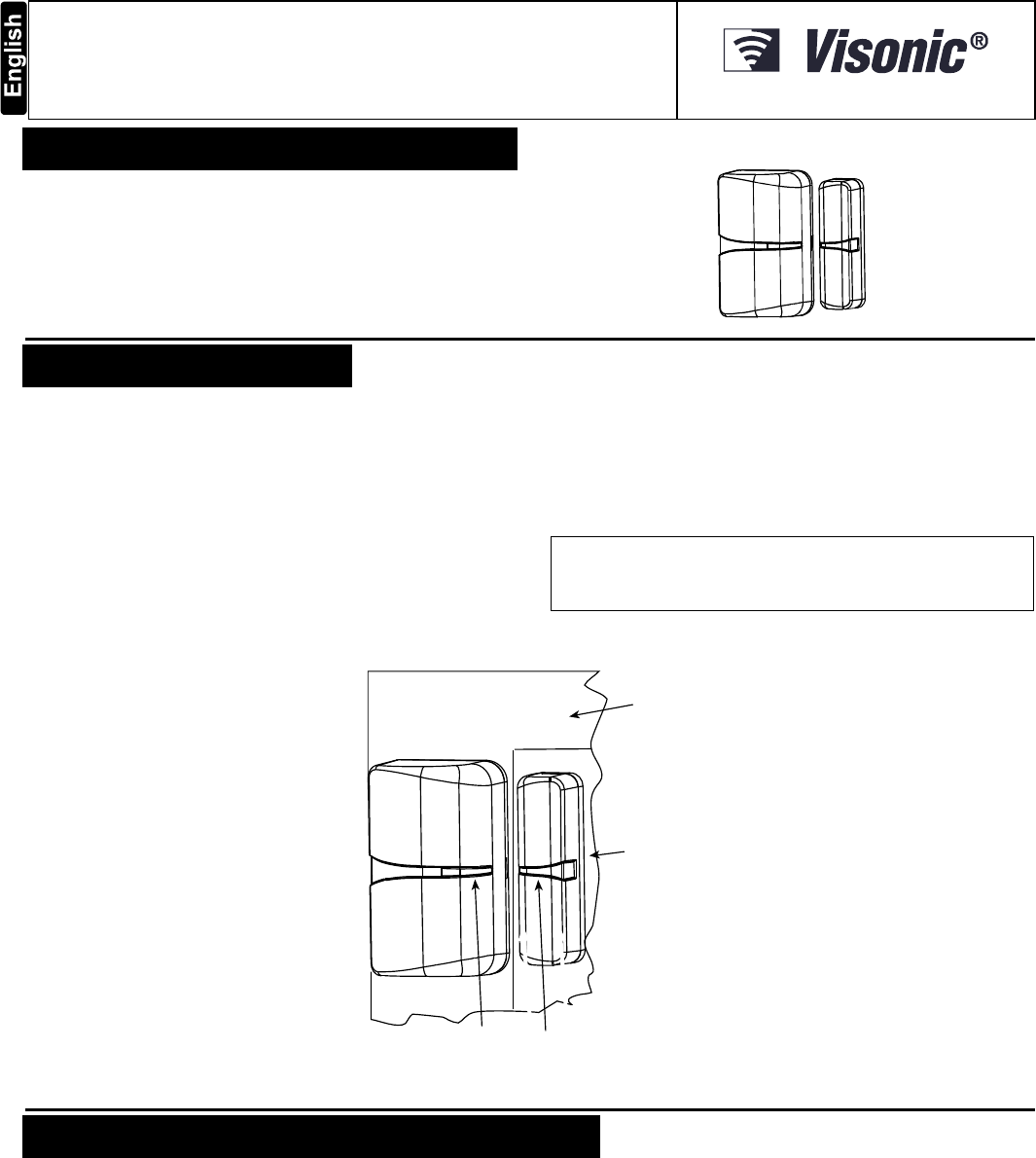
Fixed
frame
Moving
part
Transmitter & magnet
location marks
Fig. 1 – MCT-320 SMA
3. PAIRING/DEFAULTING THE SENSOR
To pair the sensor to the control panel, you must set it to pairing mode.
1. Press and hold down the sensor’s tamper switch.
2. Insert the battery into the sensor.
3. Release the tamper switch and press it again within 4 seconds.
4. Complete the pairing procedure on the control panel (see the pairing
instructions in the control panel’s installation guide).
2 D-303359 MCT-320 SMA Installation Instructions
4. MOUNTING
NOTE: It is highly recommended to attach the transmitter to the top of the door/window on the fixed frame and the magnet to the movable part (door or window).
Make sure that the magnet is located not more than 6 mm (0.25 in.) from the transmitter’s marked side.
The transmitter should be mounted on the fixed surface and the magnet on the moving surface (see Figure 1).
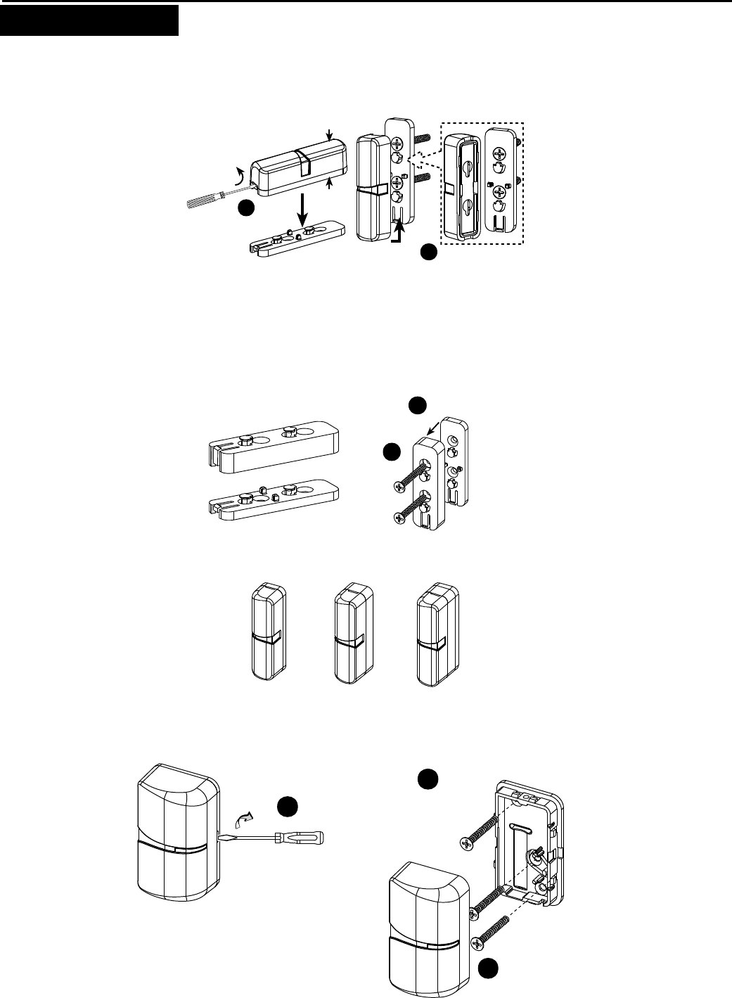
Magnet Mounting
2
A. Fasten the spacer to mounting
surface with 2 serews.
B. Locate the magnet on the spacer at
the correct direction and push it upwards
.
1
Remove
spacer
Magnet
3 mm
spacer
3mm spacer
Fig. 2 – Magnet Mounting
Magnet Mounting with Optional Spacer(s)
Optional spacer(s), 3 mm width, 7mm with, or both, can be used for the magnet mounting.
1
Join the
2 spacers
3 & 7mm
spacers
mounting
7mm spacer
3mm spacer
2
Fasten
Magnet with
3mm spacer Magnet with
7mm spacer Magnet with
3 & 7mm
spacers
Fig. 3 – Magnet Spacers
Sensor Mounting
3
2
Fasten the bracket with 3 screws
Locate and push the
transmitter on the bracket
1
Push screwdriver #2
on the “stair” and turn the
screwdriver clockwise to
separate the transmitter from
its bracket
Fig. 4 – Transmitter Mounting
D-303359 MCT-320 SMA Installation Instructions 3
5. TESTING THE SENSOR
Close the door or window, thus restoring it to the undisturbed state.
6. TROUBLESHOOTING
If you encounter one of the following problems with the MCT-320
SMA, perform the suggested remedy:
Problem Remedy
Attempt to pair the sensor is
unsuccessful. Make sure that the sensor has
been defaulted and is set to
pairing mode (see section 3).
The sensor and the panel do
not communicate. Perform the signal strength
testing procedure described in
the control panel installation
manual. Make sure that the
signal is sufficient. If
necessary, replace the
sensor’s battery.
Problem Remedy
The sensor sends a Low
Battery indication. To ensure continuous proper
operation, replace the battery
within two weeks of the first
Low Battery indication.
Panel does not arm because of
an unrecognized sensor
malfunction
Consult with your installer or
system provider before you
disable a zone.
Disable the detector zone (see
the control panel user manual).
Note that disabling a sensor
zone lowers the overall
security level of your system.
7. PRODUCT LIMITATIONS
Visonic Ltd. wireless systems are very reliable and are tested to high
standards. However, due to low transmitting power and limited range
(required by FCC and other regulatory authorities), there are some
limitations to be considered:
A. Receivers may be blocked by radio signals occurring on or near their
operating frequencies, regardless of the digital code used.
B. A receiver responds only to one transmitted signal at a time.
C. Wireless devices should be tested regularly to determine whether
there are sources of interference and to protect against faults.
The user is cautioned that changes or modifications to the unit, not
expressly approved by Visonic Ltd., could void the user’s FCC or
other authority to operate the equipment.
W.E.E.E. Product Recycling Declaration
For information regarding the recycling of this product you must contact the company from which you orignially purchased it. If you are discarding this product and not returning it
for repair then you must ensure that it is returned as identified by your supplier. This product is not to be thrown away with everyday waste.
Directive 2002/96/EC Waste Electrical and Electronic Equipment.
VISONIC LTD. (ISRAEL): P.O.B 22020 TEL-AVIV 61220 ISRAEL. PHONE: (972-3) 645-6789, FAX: (972-3) 645-6788
VISONIC INC. (U.S.A.): 65 WEST DUDLEY TOWN ROAD, BLOOMFIELD CT. 06002-1376. PHONE: (860) 243-0833, (800) 223-0020. FAX: (860) 242-8094
VISONIC LTD. (UK): UNIT 6 MADINGLEY COURT CHIPPENHAM DRIVE KINGSTON MILTON KEYNES MK10 0BZ. TEL: (0870) 7300800 FAX: (0870) 7300801
PRODUCT SUPPORT: (0870) 7300830
VISONIC GmbH (D-A-CH): KIRCHFELDSTR. 118, D-40215 DÜSSELDORF, TEL.: +49 (0)211 600696-0, FAX: +49 (0)211 600696-19
VISONIC IBERICA: ISLA DE PALMA, 32 NAVE 7, POLÍGONO INDUSTRIAL NORTE, 28700 SAN SEBASTIÁN DE LOS REYES, (MADRID), ESPAÑA. TEL (34) 91659-3120,
FAX (34) 91663-8468. www.visonic-iberica.es
INTERNET: www.visonic.com
VISONIC LTD. 2011 MCT-320 SMA D-303359 (Rev 0, 07/11)