Visonic MCT423 Wireless Smoke Detector User Manual Inst instr new
Visonic Inc. Wireless Smoke Detector Inst instr new
UserManual.wiki
>
Visonic
>
MCT423 User Manual
8 pages
Navigation menu
Upload a User Manual
Namespaces
Wiki Guide
HTML
PDF
Info
Views
User Manual
Discussion / Help
Navigation
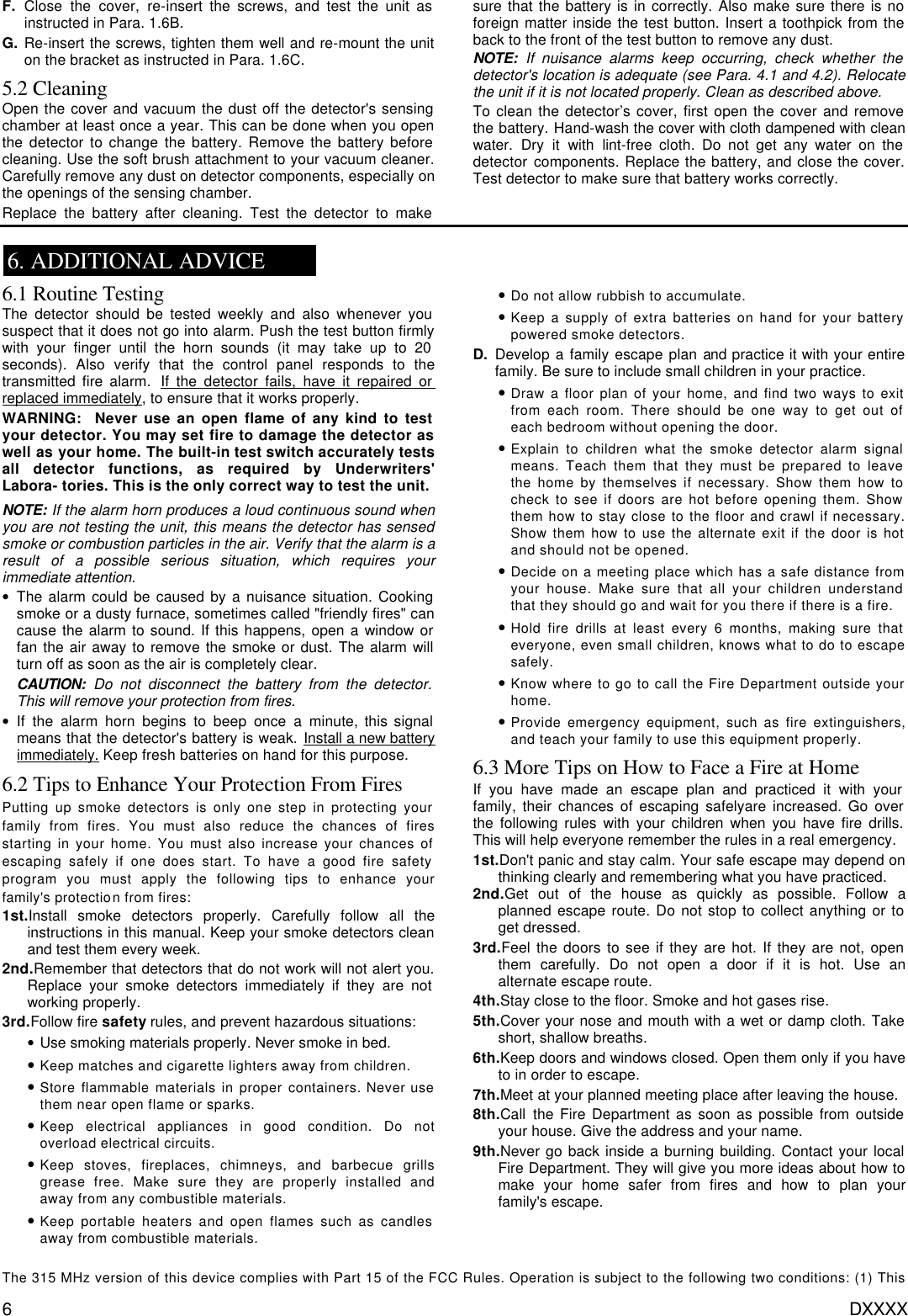
![DE3640 1 MCT-423 Supervised Wireless PowerCode Smoke Detector Installation Instructions 1. INSTALLATION SUMMARY 1.1 Disassembly A. Separate the unit from its mounting bracket as shown in Figure 1. Figure 1. Separating the MCT-423 from its Bracket B. Open the MCT-423 by pulling the cover away from the base at the point indicated by “OPEN HERE” in Figure 2. Figure 2. MCT-423 with Cover Swung Open 1.2 Setting the Function Switch The MCT-423 has a 4-position DIP switch function selector (see Figure 3). The switch levers are numbered 1 to 4, and each switch allows you to select one of two options. Open the cover and set the function switches as desired. The ON position is indicated by the arrow near the switch body. Table 1. Function selector settings Sw- Marking Pos. Selected Option Default SW-1 LED ON OFF LED will light upon transmission LED is disabled ON SW-2 RESTOREON OFF “Restore” events reported “Restore” events not reported ON SW-3 TR-REP ON OFF Alarm reported every 3 min. Alarm reported only once OFF SW-4 BAT ON OFF Lithium battery is being used Alkaline battery is being used OFF Note: Transmissions initiated by “tamper” events will be repeated once every 3 minutes, regardless of SW-3 setting. Figure 3. Transmit Indicator and Function Switch 1.3 Battery Connection and Initial Test CAUTION: The MCT-423 comes with cover latches that will prevent the cover from closing if there is no battery inside. The smoke detector is supplied with a 9V alkaline battery seated within its holder but insulated from the battery terminals. A. Pull the battery out and peel off the insulating material to expose the terminals. B. Match the battery terminals with the flexible contacts on the detector PCB. Be sure to get the polarity right. If you reverse the [+] and [–], the battery will discharge completely within a very short time through the built in protection diode! C. When the terminals are properly matched, push the battery firmly in until it is seated tightly within the holder. Note: When the battery first makes contact with the detector, the alarm horn may sound for one second. This indicates that the battery is positioned properly. D. Close the cover, then press the test button for about 5 seconds until the horn sounds two sequences of a loud 3-beep alarm. This means that the smoke detection section is working properly. 1.4 Resetting the Transmitter Module and Enrolling its PowerCode ID A tamper protection switch is mounted on the transmitter board. The tamper actuator, extending through a hole in the base (see Figure 4), is pressed against the bracket when the unit is attached to the bracket. Removal of the unit from the bracket will cause the switch contacts to open, creating a tamper event, which will be reported by the transmitter to the control panel. Figure 4. Tamper Switch](https://usermanual.wiki/Visonic/MCT423/User-Guide-84701-Page-1.png)