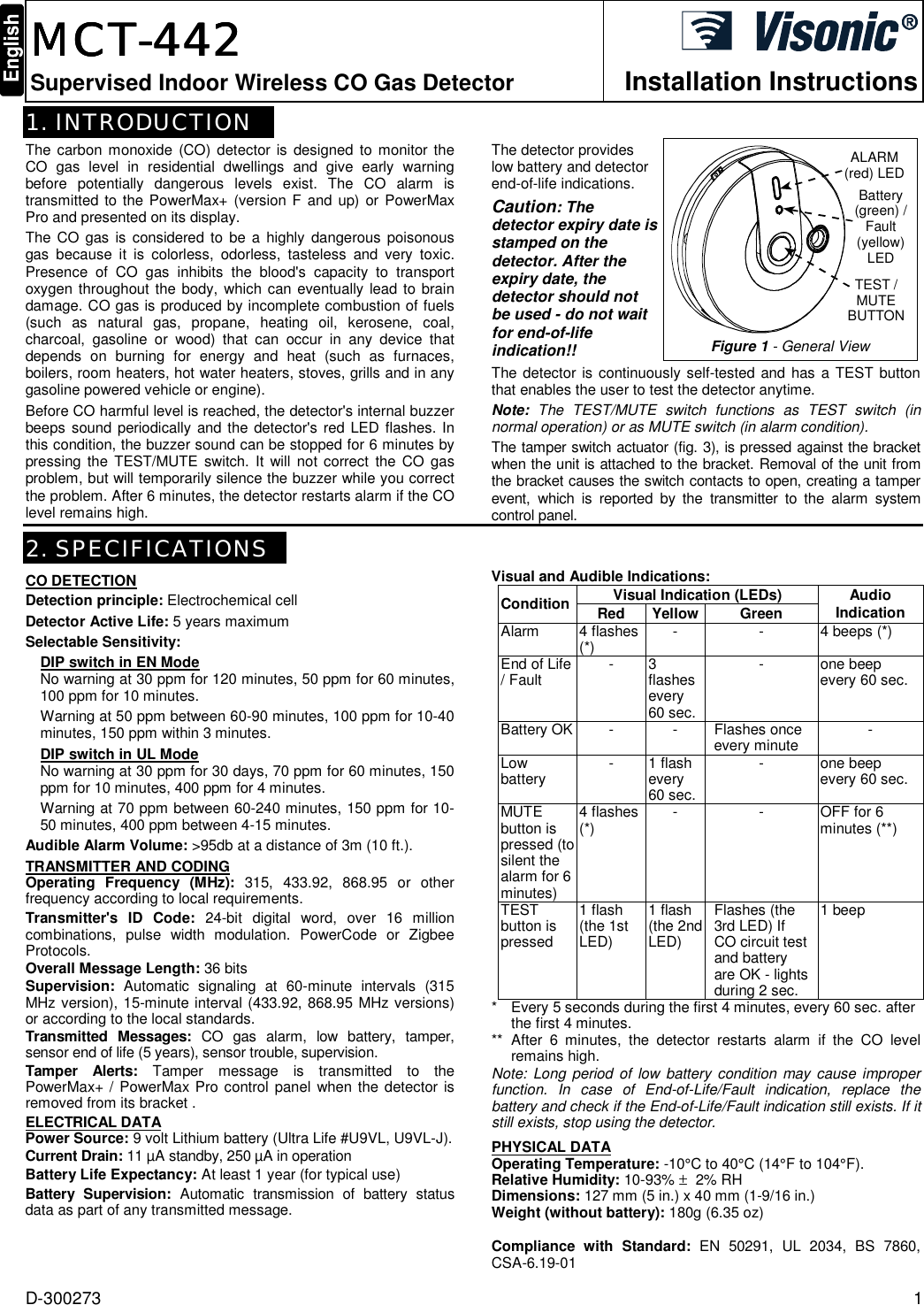
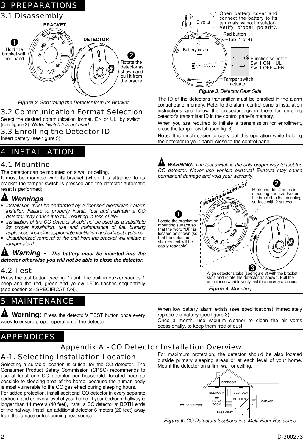
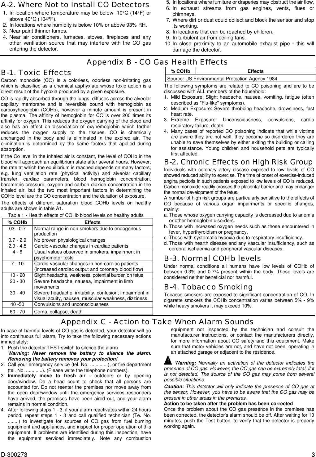
Visonic MCT442 Supervised Indoor Wireless CO Gas Detector User Manual

Visonic Inc. Supervised Indoor Wireless CO Gas Detector Users Manual

Users Manual

D-300273  1  MCTMCTMCTMCT----442442442442    Supervised Indoor Wireless CO Gas Detector Installation Instructions1. INTRODUCTION The carbon monoxide (CO) detector is designed to monitor the CO gas level in residential dwellings and give early warning before potentially dangerous levels exist. The CO alarm is transmitted to the PowerMax+ (version F and up) or PowerMax Pro and presented on its display. The CO gas is considered to be a highly dangerous poisonous gas because it is colorless, odorless, tasteless and very toxic. Presence of CO gas inhibits the blood's capacity to transport oxygen throughout the body, which can eventually lead to brain damage. CO gas is produced by incomplete combustion of fuels (such as natural gas, propane, heating oil, kerosene, coal, charcoal, gasoline or wood) that can occur in any device that depends on burning for energy and heat (such as furnaces, boilers, room heaters, hot water heaters, stoves, grills and in any gasoline powered vehicle or engine).  Before CO harmful level is reached, the detector's internal buzzer beeps sound periodically and the detector's red LED flashes. In this condition, the buzzer sound can be stopped for 6 minutes by pressing the TEST/MUTE switch. It will not correct the CO gas problem, but will temporarily silence the buzzer while you correct the problem. After 6 minutes, the detector restarts alarm if the CO level remains high.  The detector provides low battery and detector end-of-life indications. Caution: The detector expiry date is stamped on the detector. After the expiry date, the detector should not be used - do not wait for end-of-life indication!! Battery(green) /Fault(yellow)LEDTEST /MUTEBUTTONALARM(red) LEDFigure 1 - General View The detector is continuously self-tested and has a TEST button that enables the user to test the detector anytime. Note:  The TEST/MUTE switch functions as TEST switch (in normal operation) or as MUTE switch (in alarm condition). The tamper switch actuator (fig. 3), is pressed against the bracket when the unit is attached to the bracket. Removal of the unit from the bracket causes the switch contacts to open, creating a tamper event, which is reported by the transmitter to the alarm system control panel. 2. SPECIFICATIONS CO DETECTION Detection principle: Electrochemical cell Detector Active Life: 5 years maximum Selectable Sensitivity:  DIP switch in EN Mode No warning at 30 ppm for 120 minutes, 50 ppm for 60 minutes, 100 ppm for 10 minutes. Warning at 50 ppm between 60-90 minutes, 100 ppm for 10-40 minutes, 150 ppm within 3 minutes. DIP switch in UL Mode No warning at 30 ppm for 30 days, 70 ppm for 60 minutes, 150 ppm for 10 minutes, 400 ppm for 4 minutes. Warning at 70 ppm between 60-240 minutes, 150 ppm for 10-50 minutes, 400 ppm between 4-15 minutes. Audible Alarm Volume: >95db at a distance of 3m (10 ft.). TRANSMITTER AND CODING Operating Frequency (MHz): 315, 433.92, 868.95 or other frequency according to local requirements. Transmitter's ID Code: 24-bit digital word, over 16 million combinations, pulse width modulation. PowerCode or Zigbee Protocols. Overall Message Length: 36 bits Supervision: Automatic signaling at 60-minute intervals (315 MHz version), 15-minute interval (433.92, 868.95 MHz versions) or according to the local standards. Transmitted Messages: CO gas alarm, low battery, tamper, sensor end of life (5 years), sensor trouble, supervision. Tamper Alerts: Tamper message is transmitted to the PowerMax+ / PowerMax Pro control panel when the detector is removed from its bracket .  ELECTRICAL DATA Power Source: 9 volt Lithium battery (Ultra Life #U9VL, U9VL-J). Current Drain: 11 µA standby, 250 µA in operation Battery Life Expectancy: At least 1 year (for typical use) Battery Supervision: Automatic transmission of battery status data as part of any transmitted message. Visual and Audible Indications: Visual Indication (LEDs) Condition Red Yellow Green  Audio Indication Alarm 4 flashes (*)  -  -  4 beeps (*)  End of Life / Fault  - 3 flashes every 60 sec. - one beep every 60 sec. Battery OK -  -  Flashes once every minute  - Low battery  - 1 flash every 60 sec. - one beep every 60 sec. MUTE button is pressed (to silent the alarm for 6 minutes) 4 flashes (*)  -  -  OFF for 6 minutes (**) TEST button is  pressed 1 flash (the 1st LED)   1 flash (the 2nd LED) Flashes (the 3rd LED) If CO circuit test and battery are OK - lights during 2 sec. 1 beep *  Every 5 seconds during the first 4 minutes, every 60 sec. after the first 4 minutes. ** After 6 minutes, the detector restarts alarm if the CO level remains high. Note: Long period of low battery condition may cause improper function. In case of End-of-Life/Fault indication, replace the battery and check if the End-of-Life/Fault indication still exists. If it still exists, stop using the detector. PHYSICAL DATA Operating Temperature: -10°C to 40°C (14°F to 104°F). Relative Humidity: 10-93% ±  2% RH Dimensions: 127 mm (5 in.) x 40 mm (1-9/16 in.) Weight (without battery): 180g (6.35 oz)   Compliance with Standard: EN 50291, UL 2034, BS 7860, CSA-6.19-01
2  D-300273 3. PREPARATIONS 3.1 Disassembly BRACKETDETECTOR1Hold thebracket withone hand2Rotate thedetector asshown andpull it fromthe bracket Figure 2. Separating the Detector from Its Bracket 3.2 Communication Format Selection Select the desired communication format, EN or UL, by switch 1 (see figure 3). Note: Switch 2 is not used. 3.3 Enrolling the Detector ID Insert battery (see figure 3). Battery coverFunction selector:Sw. 1 ON = ULSw. 1 OFF = EN9 voltsOpen battery cover andconnect the battery to itsterminals (without insulator).Verify proper polarity.Tamper switchactuatorTab (1 of 4)Red button Figure 3. Detector Rear Side The ID of the detector's transmitter must be enrolled in the alarm control panel memory. Refer to the alarm control panel’s installation instructions and follow the procedure given there for enrolling detector's transmitter ID in the control panel's memory.  When you are required to initiate a transmission for enrollment,  press the tamper switch (see fig. 3). Note: It is much easier to carry out this operation while holding the detector in your hand, close to the control panel.  4. INSTALLATION 4.1 Mounting The detector can be mounted on a wall or ceiling.  It must be mounted with its bracket (when it is attached to its bracket the tamper switch is pressed and the detector automatic reset is performed). ! Warnings • Installation must be performed by a licensed electrician / alarm installer. Failure to properly install, test and maintain a CO detector may cause it to fail, resulting in loss of life! • Installation of the CO detector should not be used as a substitute for proper installation, use and maintenance of fuel burning appliances, including appropriate ventilation and exhaust systems. • Unauthorized removal of the unit from the bracket will initiate a tamper alert! ! Warning -  The battery must be inserted into the detector otherwise you will not be able to close the detector. 4.2 Test Press the test button (see fig. 1) until the built-in buzzer sounds 1 beep and the red, green and yellow LEDs flashes sequentially (see section 2 - SPECIFICATION).   ! WARNING: The test switch is the only proper way to test the CO detector. Never use vehicle exhaust! Exhaust may cause permanent damage and void your warranty. 1Locate the bracket onmounting surface sothat the word “UP” islocated as shown (sothat the detectorsstickers text will beeasily readable)Mark and drill 2 holes inmounting surface. Fastenthe bracket to the mountingsurface with 2 screws.Align detector’s tabs (see figure 3) with the bracketslots and rotate the detector as shown. Pull thedetector outward to verify that it is securely attached.23UP Figure 4. Mounting   5. MAINTENANCE ! Warning: Press the detector's TEST button once every week to ensure proper operation of the detector. When low battery alarm exists (see specifications) immediately replace the battery (see figure 3). Once a month, use vacuum cleaner to clean the air vents occasionally, to keep them free of dust.  APPENDICES Appendix A - CO Detector Installation Overview A-1. Selecting Installation Location Selecting a suitable location is critical for the CO detector. The Consumer Product Safety Commission (CPSC) recommends to use at least one CO detector per household, located near as possible to sleeping area of the home, because the human body is most vulnerable to the CO gas effect during sleeping hours.  For added protection, install additional CO detector in every separate bedroom and on every level of your home. If your bedroom hallway is longer than 14 meters (40 feet), install a CO detector at BOTH ends of the hallway. Install an additional detector 6 meters (20 feet) away from the furnace or fuel burning heat source.   For maximum protection, the detector should be also located outside primary sleeping areas or at each level of your home. Mount the detector on a firm wall or ceiling. BEDROOMBEDROOM BEDROOMLIVINGROOMKITCHENBASEMENTGARAGECO DETECTOR Figure 5. CO Detectors locations in a Multi-Floor Residence
D-300273  3 A-2. Where Not to Install CO Detectors 1. In location where temperature may be below -10°C (14°F) or above 40°C (104°F). 2. In locations where humidity is below 10% or above 93% RH. 3. Near paint thinner fumes. 4. Near air conditioners, furnaces, stoves, fireplaces and any other ventilation source that may interfere with the CO gas entering the detector. 5.  In locations where furniture or draperies may obstruct the air flow. 6. In exhaust streams from gas engines, vents, flues or chimneys. 7. Where dirt or dust could collect and block the sensor and stop its working. 8. In locations that can be reached by children. 9. In turbulent air from ceiling fans. 10. In close proximity to an automobile exhaust pipe - this will damage the detector. Appendix B - CO Gas Health Effects B-1. Toxic Effects Carbon monoxide (CO) is a colorless, odorless non-irritating gas which is classified as a chemical asphyxiate whose toxic action is a direct result of the hypoxia produced by a given exposure. CO is rapidly absorbed through the lungs, diffuses across the alveolar capillary membrane and is reversible bound with hemoglobin as carboxyheoglobin (COHb), however a minute amount is present in the plasma. The affinity of hemoglobin for CO is over 200 times its affinity for oxygen. This reduces the oxygen carrying of the blood and also has an effect on dissociation of oxyhemoglobin which farther reduces the oxygen supply to the tissues. CO is chemically unchanged in the body and is eliminated in the expired air. The elimination is determined by the same factors that applied during absorption.   If the Co level in the inhaled air is constant, the level of COHb in the blood will approach an equilibrium state after several hours. However, the rate at which the equilibrium is reached depends on many factors, e.g. lung ventilation rate (physical activity) and alveolar capillary transfer, cardiac parameters, blood hemoglobin concentration, barometric pressure, oxygen and carbon dioxide concentration in the inhaled air, but the two most important factors in determining the COHb level are the CO concentration and the duration of exposure.  The effects of different saturation blood COHb levels on healthy adults are shown in table A1. Table 1 - Health effects of COHb blood levels on healthy adults % COHb  Effects 03 - 0.7  Normal range in non-smokers due to endogenous production 0.7 - 2.9  No proven physiological changes 2.9 - 4.5  Cardio-vascular changes in cardiac patients 4 - 6  Usual values observed in smokers, impairment in psychomotor tests 7 - 10  Cardio-vascular changes in non-cardiac patients (increased cardiac output and coronary blood flow) 10 - 20  Slight headache, weakness, potential burden on fetus 20 - 30  Severe headache, nausea, impairment in limb movements 30 - 40  Severe headache. irritability, confusion, impairment in visual acuity, nausea, muscular weakness, dizziness 40 -50  Convulsions and unconsciousness 60 - 70  Coma, collapse, death % COHb  Effects Source: US Environmental Protection Agency 1984 The following symptoms are related to CO poisoning and are to be discussed with ALL members of the household: 1.  Mild Exposure: Slight headache, nausea, vomiting, fatigue (often described as "Flu-like" symptoms). 2.  Medium Exposure: Severe throbbing headache, drowsiness, fast heart rate. 3. Extreme Exposure: Unconsciousness, convulsions, cardio respiratory failure, death. 4.  Many cases of reported CO poisoning indicate that while victims are aware they are not well, they become so disordered they are unable to save themselves by either exiting the building or calling for assistance. Young children and household pets are typically first affected. B-2. Chronic Effects on High Risk Group Individuals with coronary artery disease exposed to low levels of CO showed reduced ability to exercise. The time of onset of exercise-induced angina pectoris in such patients exposed to low levels of CO is reduced. Carbon monoxide readily crosses the placental barrier and may endanger the normal development of the fetus. A number of high risk groups are particularly sensitive to the effects of CO because of various organ impairments or specific changes, mainly: a. Those whose oxygen carrying capacity is decreased due to anemia or other hemoglobin disorders. b. Those with increased oxygen needs such as those encountered in fever, hyperthyroidism or pregnancy. c. Those with systematic hypoxia due to respiratory insufficiency. d. Those with hearth disease and any vascular insufficiency, such as cerebral ischaemia and peripheral vascular diseases. B-3. Normal COHb levels Under normal conditions all humans have low levels of COHb of between 0.3% and 0.7% present within the body. These levels are considered neither beneficial nor harmful. B-4. Tobacco Smoking Tobacco smokers are exposed to significant concentration of CO. In cigarette smokers the COHb concentration varies between 5% - 9% while heavy smokers it may exceed 10%.  Appendix C - Action to Take When Alarm Sounds In case of harmful levels of CO gas is detected, your detector will go into continuous full alarm, Try to take the following necessary actions immediately: 1.  Push the detector TEST switch to silence the alarm. Warning: Never remove the battery to silence the alarm. Removing the battery removes your protection! 2.  Call your emergency service (tel. No. .............), or fire department (tel. No. ............). (Please write the telephone numbers). 3.  Immediately move to fresh air - outdoors or by opening door/window. Do a head count to check that all persons are accounted for. Do not reenter the premises nor move away from the open door/window until the emergency services responders have arrived, the premises have been aired out, and your alarm remains in normal condition. 4.  After following steps 1 - 3, if your alarm reactivates within 24 hours period, repeat steps 1 - 3 and call qualified technician (Te. No.  ........) to investigate for sources of CO gas from fuel burning equipment and appliances, and inspect for proper operation of this equipment. If problems are identified during this inspection, have the equipment serviced immediately. Note any combustion equipment not inspected by the technician and consult the manufacturer instructions, or contact the manufacturers directly, for more information about CO safety and this equipment. Make sure that motor vehicles are not, and have not been, operating in an attached garage or adjacent to the residence. ! Warning: Normally an activation of the detector indicates the presence of CO gas. However, the CO gas can be extremely fatal, if it is not detected. The source of the CO gas may come from several possible situations. Caution: This detector will only indicate the presence of CO gas at the sensor. However, you have to be aware that the CO gas may be present in other areas in the premises. Action to be taken after the problem has been corrected Once the problem about the CO gas presence in the premises has been corrected, the detector's alarm should be off. After waiting for 10 minutes, push the Test button, to verify that the detector is properly working again.
4  D-300273 Appendix D - Warnings and Limitations This product is intended for use in ordinary indoor locations of family living units. It is not designed to measure compliance with Occupational Safety and Health Administration (OSHA) commercial or industrial standards. Caution: The detector will only indicate the presence of carbon monoxide gas at the sensor. Carbon monoxide gas may be present in other areas. Individuals with medical problems may consider using warning devices which provide audible and visual signals for carbon monoxide concentrations under 30 ppm. The alarm, including the sensor, is not to be located within 1.5m (5 feet) of any cooking appliance. The detector may not alarm at low carbon monoxide levels. The Occupational Safety and Health Association (OSHA) has established that continuous exposure levels of 50 ppm should not be exceeded in an 8 hours period. Individuals with medical problem may consider more sensitive detection devices. The CO gas detector is not suitable as a smoke detector or fire detector. This detector is not suitable to install in an hazardous location as defined in National Electrical Code. Carbon monoxide must reach the detector for proper performance of CO gas detection. The detector may not protect people who are at special risk from carbon monoxide exposure by reason of age, pregnancy or medical condition. In doubt, consult your medical practitioner.  CO detectors may wear out because they contain electronic parts that fail at any time. Test your detector at least every week. Instruct children never to play with the detector. Never use detergents or other solvents to clean the detector. Avoid spraying air fresheners, hair spray, paint or other aerosols near the detector. Do not paint the detector. Paint will seal the detectors vents and interfere detecting CO gas. Detailed information on conditions which can result in transient CO situations: 1. Excessive spillage or reverse venting of fuel burning appliances caused by: a. Outdoor ambient conditions such as wind direction and/or velocity, including high gusts of wind; heavy air in the vent pipes (cold/humid air with extended periods between cycles). b.  Negative pressure differential resulting from the use of exhaust fans. c. Simultaneous operation of several fuel burning appliances competing for limited internal air. d. Vent pipe connection vibrating loose from clothes dryers, furnaces, or water heaters. e. Obstructions in or unconventional vent pipe designs which amplify the above situations. 2. Extended operation of unvented fuel burning devices (range, oven, fireplace, etc.). 3.  Temperature inversions which can trap exhaust gasses near the ground. 4.  Car idling in an open or closed attached garage, or near a home. Appendix E - Trouble-shooting  Problem  This means...  You should... Every 60 seconds, the yellow LED flashes once and 1 beep is heard.  Low battery warning  Replace battery (see SPECIFICATIONS). When TEST/MUTE button is pressed, the green LED flashes instead of lighting during 2 seconds.  Detector fault or the battery is not OK.  Replace battery (see SPECIFICATIONS). If the problem still exists, replace detector. Every 60 seconds, there are 3 flashes of the yellow LED and 1 beep is heard.  Detector end of life/ fault.  Replace battery (see SPECIFICATIONS). If the problem still exists, replace detector. CO detector goes back into alarm 6 minutes after the TEST/MUTE button is pressed.  CO level indicates a potentially dangerous situation.  If you are feeling symptoms of CO poisoning, evacuate your home and call your emergency service. CO detector alarms frequently even though no high levels of CO are revealed in an investigation.  The CO detector may be improperly located.  Relocate the detector - see appendix A. If frequent alarms continue, have home rechecked for potential CO problems. You may experiencing an intermittent CO problem. Warning! Changes or modifications to this equipment not expressly approved by Visonic Ltd. could void the user’s authority to operate the equipment. The 315 MHz version of this device complies with Part 15 of the FCC Rules. Operation is subject to the following two conditions: (1) This device may not cause harmful interference, and (2) This device must accept any interference received, including interference that may cause undesired operation. The digital circuit of this device has been tested and found to comply with the limits for a Class B digital device, pursuant to Part 15 of the FCC Rules. These limits are designed to provide reasonable protection against harmful interference in residential installations. This equipment generates, uses and can radiate radio frequency energy and, if not installed and used in accordance with the instructions, may cause harmful interference to radio and television reception. However, there is no guarantee that interference will not occur in a particular installation. If this device does cause such interference, which can be verified by turning the device off and on, the user is encouraged to eliminate the interference by one or more of the following measures: –  Re-orient or re-locate the receiving antenna. –  Increase the distance between the device and the receiver. –  Connect the device to an outlet on a circuit different from the one which supplies power to the receiver. –  Consult the dealer or an experienced radio/TV technician.  WARRANTY  Visonic Ltd. and/or its subsidiaries and its affiliates ("the Manufacturer") warrants its products hereinafter referred to as "the Product" or "Products" to be in conformance with its own plans and specifications and to be free of defects in materials and workmanship under normal use and service for a period of twelve months from the date of shipment by the Manufacturer.  The Manufacturer's obligations shall be limited within the warranty period, at its option, to repair or replace the product or any part thereof. The Manufacturer shall not be responsible for dismantling and/or reinstallation charges. To exercise the warranty the product must be returned to the Manufacturer freight prepaid and insured. This warranty does not apply in the following cases: improper installation, misuse, failure to follow installation and operating instructions, alteration, abuse, accident or tampering, and repair by anyone other than the Manufacturer. This warranty is exclusive and expressly in lieu of all other warranties, obligations or liabilities, whether written, oral, express or implied, including any warranty of merchantability or fitness for a particular purpose, or otherwise.  In no case shall the Manufacturer be liable to anyone for any consequential or incidental damages for breach of this warranty or any other warranties whatsoever, as aforesaid. This warranty shall not be modified, varied or extended, and the Manufacturer does not authorize any person to act on its behalf in the modification, variation or extension of this warranty. This warranty shall apply to the Product only.  All products, accessories or attachments of others used in conjunction with the Product, including  batteries, shall be covered solely by their own warranty, if any.  The Manufacturer shall not be liable for any damage or loss whatsoever, whether directly, indirectly, incidentally, consequentially or otherwise, caused by the malfunction of the Product due to products, accessories, or attachments of others, including batteries, used in conjunction with the Products. The Manufacturer does not represent that its Product may not be compromised and/or circumvented, or that the Product will prevent any death, personal and/or bodily injury and/or damage to property resulting from burglary, robbery, fire or otherwise, or that the Product will in all cases provide adequate warning or protection. User understands that a properly installed and maintained alarm may only reduce the risk of events such as burglary, robbery, and fire without warning, but it is not insurance or a guarantee that such will not occur or that there will be no death, personal damage and/or damage to property as a result. The Manufacturer shall have no liability for any death, personal and/or bodily injury and/or damage to property or other loss whether direct, indirect, incidental, consequential or otherwise, based on a claim that the Product failed to function.  However, if the Manufacturer is held liable, whether directly or indirectly, for any loss or damage arising under this limited warranty or otherwise, regardless of cause or origin, the Manufacturer's maximum liability shall not in any case exceed the purchase price of the Product, which shall be fixed as liquidated damages and not as a penalty, and shall be the complete and exclusive remedy against the Manufacturer. Warning: The user should follow the installation and operation instructions and among other things test the Product and the whole system at least once a week.  For various reasons, including, but not limited to, changes in environmental conditions, electric or electronic disruptions and tampering, the Product may not perform as expected.  The user is advised to take all necessary precautions for his /her safety and the protection of his/her property. 6/91   W.E.E.E. Product Recycling Declaration For  information regarding the recycling  of this product  you must contact the  company from which you orignially purchased it. If you are discarding this product and not returning it for repair then you must ensure that it is returned as identified by your supplier. This product is not to be thrown away with everyday waste. Directive 2002/96/EC Waste Electrical and Electronic Equipment.   VISONIC LTD. (ISRAEL): P.O.B 22020 TEL-AVIV 61220 ISRAEL. PHONE: (972-3) 645-6789, FAX: (972-3) 645-6788 VISONIC INC. (U.S.A.): 10 NORTHWOOD DRIVE, BLOOMFIELD CT. 06002-1376. PHONE: (860) 243-0833, (800) 223-0020 FAX: (860) 242-8094 VISONIC LTD. (UK): FRASER ROAD, PRIORY BUSINESS PARK, BEDFORD MK44 3WH. PHONE: (0870) 7300800 FAX: (0870) 7300801 INTERNET: www.visonic.com VISONIC LTD. 2006  MCT-442   D-300273 (REV. 0, 4/06)

Navigation menu