Visonic MCTIR252 Dual RF and IR Transmitter User Manual DE2411U0

Visonic Inc. Dual RF and IR Transmitter DE2411U0

Contents

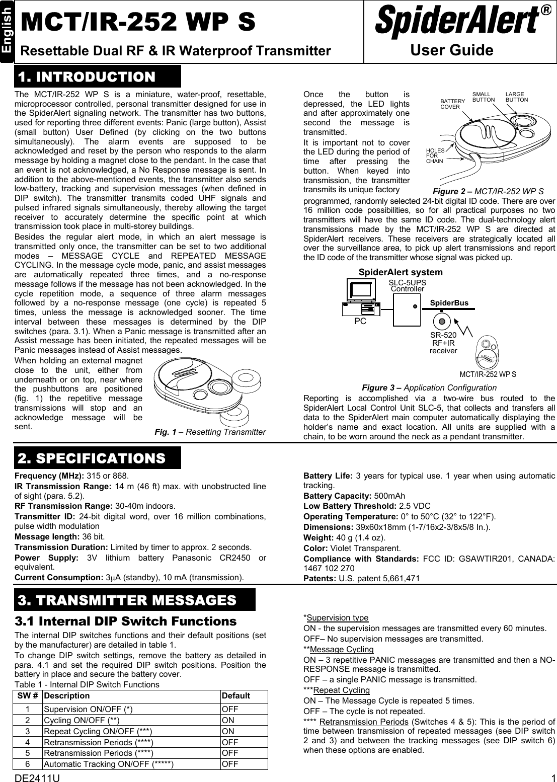
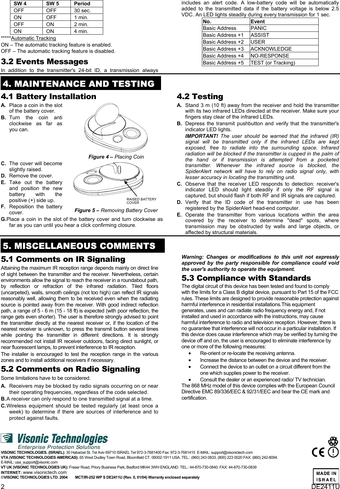
Users Manual Original

DE2411U  1 MCT/IR-252 WP S Resettable Dual RF & IR Waterproof Transmitter   User Guide 1. INTRODUCTIONThe MCT/IR-252 WP S is a miniature, water-proof, resettable, microprocessor controlled, personal transmitter designed for use in the SpiderAlert signaling network. The transmitter has two buttons, used for reporting three different events: Panic (large button), Assist (small button) User Defined (by clicking on the two buttons simultaneously). The alarm events are supposed to be acknowledged and reset by the person who responds to the alarm message by holding a magnet close to the pendant. In the case that an event is not acknowledged, a No Response message is sent. In addition to the above-mentioned events, the transmitter also sends low-battery, tracking and supervision messages (when defined in DIP switch). The transmitter transmits coded UHF signals and pulsed infrared signals simultaneously, thereby allowing the target receiver to accurately determine the specific point at which transmission took place in multi-storey buildings.  Besides the regular alert mode, in which an alert message is transmitted only once, the transmitter can be set to two additional modes – MESSAGE CYCLE and REPEATED MESSAGE CYCLING. In the message cycle mode, panic, and assist messages are automatically repeated three times, and a no-response message follows if the message has not been acknowledged. In the cycle repetition mode, a sequence of three alarm messages followed by a no-response message (one cycle) is repeated 5 times, unless the message is acknowledged sooner. The time interval between these messages is determined by the DIP switches (para. 3.1). When a Panic message is transmitted after an Assist message has been initiated, the repeated messages will be Panic messages instead of Assist messages. When holding an external magnet close to the unit, either from underneath or on top, near where the pushbuttons are positioned (fig. 1) the repetitive message transmissions will stop and an acknowledge message will be sent.    Fig. 1 – Resetting Transmitter Once the button is depressed, the LED lights and after approximately one second the message is transmitted.  It is important not to cover the LED during the period of time after pressing the button. When keyed into transmission, the transmitter transmits its unique factory  LARGEBUTTONSMALLBUTTONBATTERYCOVERHOLESFORCHAIN Figure 2 – MCT/IR-252 WP S programmed, randomly selected 24-bit digital ID code. There are over 16 million code possibilities, so for all practical purposes no two transmitters will have the same ID code. The dual-technology alert transmissions made by the MCT/IR-252 WP S are directed at SpiderAlert receivers. These receivers are strategically located all over the surveillance area, to pick up alert transmissions and report the ID code of the transmitter whose signal was picked up. SpiderAlert systemSLC-5UPSControllerPCSR-520RF+IRreceiverSpiderBusMCT/IR-252 WP S Figure 3 – Application Configuration Reporting is accomplished via a two-wire bus routed to the SpiderAlert Local Control Unit SLC-5, that collects and transfers all data to the SpiderAlert main computer automatically displaying the holder’s name and exact location. All units are supplied with a chain, to be worn around the neck as a pendant transmitter.  2. SPECIFICATIONSFrequency (MHz): 315 or 868. IR Transmission Range: 14 m (46 ft) max. with unobstructed line of sight (para. 5.2). RF Transmission Range: 30-40m indoors. Transmitter ID: 24-bit digital word, over 16 million combinations, pulse width modulation Message length: 36 bit. Transmission Duration: Limited by timer to approx. 2 seconds. Power Supply: 3V lithium battery Panasonic CR2450 or equivalent. Current Consumption: 3µA (standby), 10 mA (transmission). Battery Life: 3 years for typical use. 1 year when using automatic tracking. Battery Capacity: 500mAh Low Battery Threshold: 2.5 VDC Operating Temperature: 0° to 50°C (32° to 122°F). Dimensions: 39x60x18mm (1-7/16x2-3/8x5/8 In.). Weight: 40 g (1.4 oz). Color: Violet Transparent. Compliance with Standards: FCC ID: GSAWTIR201, CANADA: 1467 102 270 Patents: U.S. patent 5,661,471  3. TRANSMITTER MESSAGES3.1 Internal DIP Switch Functions The internal DIP switches functions and their default positions (set by the manufacturer) are detailed in table 1. To change DIP switch settings, remove the battery as detailed in para. 4.1 and set the required DIP switch positions. Position the battery in place and secure the battery cover. Table 1 - Internal DIP Switch Functions SW #  Description  Default  1  Supervision ON/OFF (*)  OFF 2  Cycling ON/OFF (**)   ON 3  Repeat Cycling ON/OFF (***)  ON 4  Retransmission Periods (****)  OFF 5  Retransmission Periods (****)  OFF 6  Automatic Tracking ON/OFF (*****)  OFF *Supervision type ON - the supervision messages are transmitted every 60 minutes. OFF– No supervision messages are transmitted. **Message Cycling ON – 3 repetitive PANIC messages are transmitted and then a NO-RESPONSE message is transmitted. OFF – a single PANIC message is transmitted. ***Repeat Cycling ON – The Message Cycle is repeated 5 times.  OFF – The cycle is not repeated. **** Retransmission Periods (Switches 4 & 5): This is the period of time between transmission of repeated messages (see DIP switch 2 and 3) and between the tracking messages (see DIP switch 6) when these options are enabled.
2  DE2411U SW 4  SW 5  Period  OFF OFF 30 sec. ON OFF 1 min. OFF ON 2 min. ON ON 4 min. *****Automatic Tracking ON – The automatic tracking feature is enabled.  OFF – The automatic tracking feature is disabled. 3.2 Events Messages In addition to the transmitter's 24-bit ID, a transmission always includes an alert code. A low-battery code will be automatically added to the transmitted data if the battery voltage is below 2.5 VDC. An LED lights steadily during every transmission for 1 sec.  No. Event Basic Address  PANIC Basic Address +1  ASSIST Basic Address +2  USER Basic Address +3  ACKNOWLEDGE Basic Address +4  NO-RESPONSE Basic Address +5  TEST (or Tracking)  4. MAINTENANCE AND TESTING 4.1 Battery Installation  A.   Place a coin in the slot of the battery cover.  B.  Turn the coin anti clockwise as far as you can.  Figure 4 – Placing Coin C.   The cover will become slightly raised.  D.   Remove the cover.  E.  Take out the battery and position the new battery with the positive (+) side up.  F.   Reposition the battery cover.   RAISED BATTERYCOVER  Figure 5 – Removing Battery Cover G. Place a coin in the slot of the battery cover and turn clockwise as far as you can until you hear a click confirming closure.   4.2 Testing  A.   Stand 3 m (10 ft) away from the receiver and hold the transmitter with its two infrared LEDs directed at the receiver. Make sure your fingers stay clear of the infrared LEDs.  B.   Depress the transmit pushbutton and verify that the transmitter's indicator LED lights.  IMPORTANT! The user should be warned that the infrared (IR) signal will be transmitted only if the infrared LEDs are kept exposed, free to radiate into the surrounding space. Infrared radiation will be blocked if the transmitter is cupped in the palm of the hand or if transmission is attempted from a pocketed transmitter. Whenever the infrared source is blocked, the SpiderAlert network will have to rely on radio signal only, with lesser accuracy in locating the transmitting unit.  C.  Observe that the receiver LED responds to detection: receiver's indicator LED should light steadily if only the RF signal is captured, but should flash if both RF and IR signals are captured.  D.  Verify that the ID code of the transmitter in use has been registered by the SpiderAlert head-end computer.  E.   Operate the transmitter from various locations within the area covered by the receiver to determine "dead" spots, where transmission may be obstructed by walls and large objects, or affected by structural materials.  5. MISCELLANEOUS COMMENTS  5.1 Comments on IR Signaling  Attaining the maximum IR reception range depends mainly on direct line of sight between the transmitter and the receiver. Nevertheless, certain environments allow the signal to reach the receiver in a roundabout path, by reflection or refraction of the infrared radiation. Tiled floors (uncarpeted), walls, smooth ceilings (not too high) can reflect IR signals reasonably well, allowing them to be received even when the radiating source is pointed away from the receiver. With good indirect reflection path, a range of 5 - 6 m (15 - 18 ft) is expected (with poor reflection, the range gets even shorter). The user is therefore strongly advised to point the transmitter directly at the nearest receiver or, if the location of the nearest receiver is unknown, to press the transmit button several times while pointing the transmitter in different directions. It is strongly recommended not install IR receiver outdoors, facing direct sunlight, or near fluorescent lamps, to prevent interference to IR reception.  The installer is encouraged to test the reception range in the various zones and to install additional receivers if necessary. 5.2 Comments on Radio Signaling  Some limitations have to be considered.  A.   Receivers may be blocked by radio signals occurring on or near their operating frequencies, regardless of the code selected.  B. A receiver can only respond to one transmitted signal at a time.  C. Wireless equipment should be tested regularly (at least once a week) to determine if there are sources of interference and to protect against faults. Warning: Changes or modifications to this unit not expressly approved by the party responsible for compliance could void the user's authority to operate the equipment. 5.3 Compliance with Standards  The digital circuit of this device has been tested and found to comply with the limits for a Class B digital device, pursuant to Part 15 of the FCC rules. These limits are designed to provide reasonable protection against harmful interference in residential installations.This equipment generates, uses and can radiate radio frequency energy and, if not installed and used in accordance with the instructions, may cause harmful interference to radio and television reception. However, there is no guarantee that interference will not occur in a particular installation. If this device does cause interference which may be verified by turning the device off and on, the user is encouraged to eliminate interference by one or more of the following measures: • Re-orient or re-locate the receiving antenna. • Increase the distance between the device and the receiver. • Connect the device to an outlet on a circuit different from the one which supplies power to the receiver. • Consult the dealer or an experienced radio/ TV technician. The 868 MHz model of this device complies with the European Council Directive EMC 89/336/EEC & 92/31/EEC and bear the CE mark and certification.    VISONIC TECHNOLOGIES. (ISRAEL): 30 Habarzel St. Tel Aviv 69710 ISRAEL Tel 972-3-7681400 Fax: 972-3-7681415  E-MAIL: support@visonictech.com VTA (VISONIC TECHNOLOGIES AMERICAS): 65 West Dudley Town Road, Bloomfield CT. 06002-1911 USA. TEL.: (860) 243 0833, (800) 223 0020 FAX: (860) 242-8094.  E-MAIL: usa_support@visonic.com  VT UK (VISONIC TECHNOLOGIES UK): Fraser Road, Priory Business Park, Bedford MK44 3WH ENGLAND. TEL.: 44-870-730-0840; FAX: 44-870-730-0839  INTERNET: www.visonictech.com ©VISONIC TECHNOLOGIES LTD. 2004        MCT/IR-252 WP S DE2411U (Rev. 0, 01/04) Warranty enclosed separately

Navigation menu