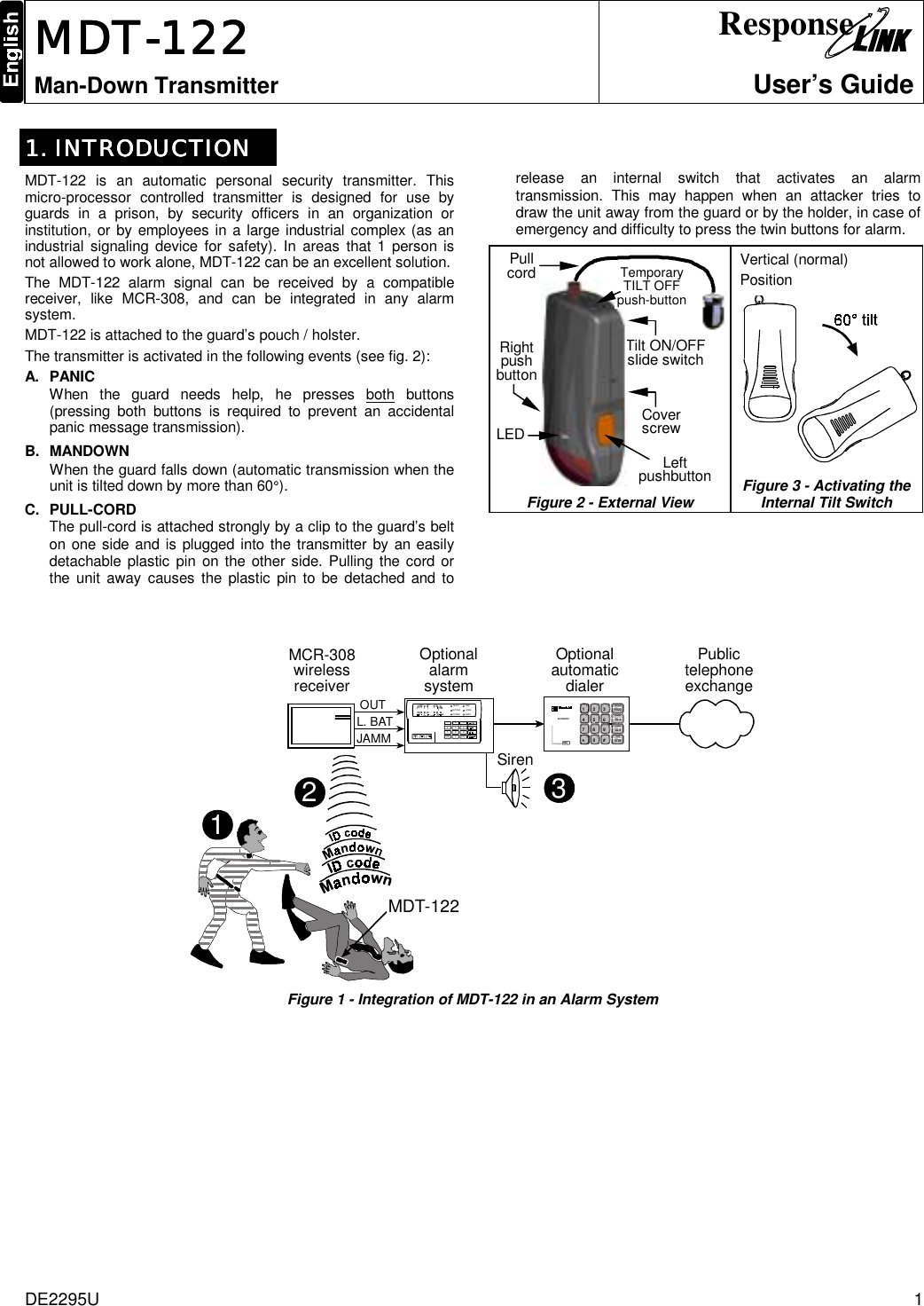
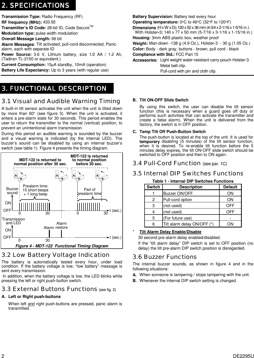
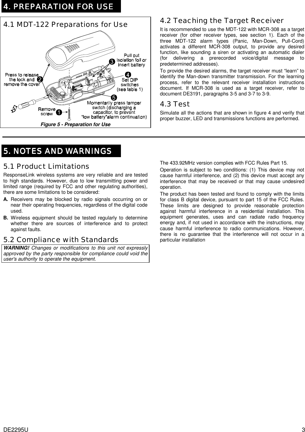
Visonic MDT122 Personal Security Transmitter User Manual

Visonic Inc. Personal Security Transmitter Users Manual

Users Manual

DE2295U  1  MDTMDTMDTMDT----122 122 122 122     Man-Down Transmitter Response  User’s Guide  1. INTRODUCTION1. INTRODUCTION1. INTRODUCTION1. INTRODUCTION    MDT-122 is an automatic personal security transmitter. This micro-processor controlled transmitter is designed for use by guards in a prison, by security officers in an organization or institution, or by employees in a large industrial complex (as an industrial signaling device for safety). In areas that 1 person is not allowed to work alone, MDT-122 can be an excellent solution.  The MDT-122 alarm signal can be received by a compatible receiver, like MCR-308, and can be integrated in any alarm system. MDT-122 is attached to the guard’s pouch / holster. The transmitter is activated in the following events (see fig. 2): A.  PANIC When the guard needs help, he presses both buttons (pressing both buttons is required to prevent an accidental panic message transmission). B.  MANDOWN When the guard falls down (automatic transmission when the unit is tilted down by more than 60°). C.  PULL-CORD  The pull-cord is attached strongly by a clip to the guard’s belt on one side and is plugged into the transmitter by an easily detachable plastic pin on the other side. Pulling the cord or the unit away causes the plastic pin to be detached and to release an internal switch that activates an alarm transmission. This may happen when an attacker tries to draw the unit away from the guard or by the holder, in case of emergency and difficulty to press the twin buttons for alarm.            Figure 2 - External View            Figure 3 - Activating the Internal Tilt Switch   MDT-1222MCR-308wirelessreceiver1PublictelephoneexchangeOUTL. BATJAMMREADYBYPASSPOWERARMHOMEAWAYND147CLR2580369ENTABCD2OptionalalarmsystemOptionalautomaticdialerAUTOM ATIC2 - CHANNELSPEECH DIALERDIALModel: DL-BCDEFA-F APROGSTOPAL-1AL-2PROGRAMALARM-1ALARM-2STOP3456789*0#123Siren Figure 1 - Integration of MDT-122 in an Alarm System   Vertical (normal) Position  Left pushbutton Tilt ON/OFF slide switch  Pull cord  Cover screw  Right push button LED   Temporary TILT OFF push-button
2 DE2295U  2. SPECIFICATIONS2. SPECIFICATIONS2. SPECIFICATIONS2. SPECIFICATIONS    Transmission Type: Radio Frequency (RF) RF frequency (MHz): 433.92 Transmitter’s ID Code: 28-bit ID, Code SecureTM Modulation type: pulse width modulation Overall Message Length: 66 bit Alarm Messages: Tilt activated, pull-cord disconnected, Panic alarm, each with separate ID Power Source: 3.6 V, Lithium battery, size 1/2 AA / 1.2 Ah, (Tadiran TL-2150 or equivalent.)  Current Consumption: 15µA standby, 10mA (operation)  Battery Life Expectancy: Up to 3 years (with regular use) Battery Supervision: Battery test every hour  Operating temperature: 0°C to 49°C (32°F to 120°F) Dimensions (H x W x D): 120 x 52 x 36 mm (4-3/4 x 2-1/16 x 1-5/16 in.)    With Holster-3: 140 x 77 x 50 mm (5-7/16 x 3-1/16 x 1-15/16 in.) Housing: 3mm ABS plastic box, weather proof Weight: Man-down -138 g (4.9 Oz.), Holster-3  - 30 g (1.05 Oz.)  Color: Body - dark gray, buttons - brown, pull cord - black Compliance with Std.: FCC Part 15 Accessories:  Light weight water-resistant carry pouch Holster-3.     Metal belt clip.     Pull-cord with pin and cloth clip.   3. FUNCTIONAL DESCRIPTION3. FUNCTIONAL DESCRIPTION3. FUNCTIONAL DESCRIPTION3. FUNCTIONAL DESCRIPTION    3.1 Visual and Audible Warning Timing A built-in tilt sensor activates the unit when the unit is tilted down by more than 60° (see figure 3). When the unit is activated, it enters a pre-alarm state for 30 seconds. This period enables the user to return the transmitter to the normal (vertical) position, to prevent an unintentional alarm transmission.  During this period an audible warning is sounded by the buzzer and a visual warning is indicated (by the internal LED). The buzzer’s sound can be disabled by using an internal buzzer’s switch (see table 1). Figure 4 presents the timing diagram.  Prealarm time:15 short beeps+ 1 long beepBuzzersound030 t (sec.)MDT-122 is returnedto normal positionbefore 30 sec.030MDT-122 is returned tonormal position after 30 sec.ONOFFPart ofprealarm timeTransmissionand LED030 t (sec.)Alarm AlarmrestoreONOFF  Figure 4 - MDT-122  Functional Timing Diagram 3.2 Low Battery Voltage Indication  The battery is automatically tested every hour, under load condition. If the battery voltage is low, “low battery” message is sent every transmission.  In addition, when the battery voltage is low, the LED blinks while pressing the left or right push-button switch.  3.3 External Buttons Functions (see fig. 2)  A. Left or Right push-buttons When left and right push-buttons are pressed, panic alarm is transmitted.  B. Tilt ON-OFF Slide Switch By using this switch, the user can disable the tilt sensor function (this is necessary when a guard goes off duty or performs such activities that can activate the transmitter and create a false alarm). When the unit is delivered from the factory, the switch is in OFF position. C. Temp Tilt Off Push-Button Switch The push-button is located at the top of the unit. It is used for temporary disabling (5 minutes) of the tilt sensor function, when it is desired. To re-enable tilt function before the 5 minutes delay expires, the tilt ON-OFF slide switch should be switched to OFF position and then to ON again. 3.4 Pull-Cord Function (see par. 1C) 3.5 Internal DIP Switches Functions Table 1 - Internal DIP Switches Functions Switch Description  Default 1 Buzzer ON/OFF  ON 2  Pull-cord option   ON 3 (not used)  OFF 4 (not used)  OFF 5  (For future use)  - 6  Tilt alarm delay ON/OFF (*)  ON *    Tilt Alarm Delay Enable/Disable 30 second pre-alarm delay enabled/disabled. If the “tilt alarm delay” DIP switch is set to OFF position (no delay) the tilt pre-alarm DIP switch position is disregarded. 3.6 Buzzer Functions The internal buzzer sounds, as shown in figure 4 and in the following situations: A.  When someone is tampering / stops tampering with the unit.  B.  Whenever the internal DIP switch setting is changed.
DE2295U  3 4. PREPARATION FOR USE4. PREPARATION FOR USE4. PREPARATION FOR USE4. PREPARATION FOR USE     4.1 MDT-122 Preparations for Use  Figure 5 - Preparation for Use      4.2 Teaching the Target Receiver It is recommended to use the MDT-122 with MCR-308 as a target receiver (for other receiver types, see section 1). Each of the three MDT-122 alarm types (Panic, Man-Down, Pull-Cord) activates a different MCR-308 output, to provide any desired function, like sounding a siren or activating an automatic dialer (for delivering a prerecorded voice/digital message to predetermined addresses). To provide the desired alarms, the target receiver must “learn” to identify the Man-down transmitter transmission. For the learning process, refer to the relevant receiver installation instructions document. If MCR-308 is used as a target receiver, refer to document DE3191, paragraphs 3-5 and 3-7 to 3-9. 4.3 Test Simulate all the actions that are shown in figure 4 and verify that proper buzzer, LED and transmissions functions are performed.    5. NOTES AND WARNINGS5. NOTES AND WARNINGS5. NOTES AND WARNINGS5. NOTES AND WARNINGS    5.1 Product Limitations ResponseLink wireless systems are very reliable and are tested to high standards. However, due to low transmitting power and limited range (required by FCC and other regulating authorities), there are some limitations to be considered: A. Receivers may be blocked by radio signals occurring on or near their operating frequencies, regardless of the digital code used. B. Wireless equipment should be tested regularly to determine whether there are sources of interference and to protect against faults. 5.2 Compliance with Standards WARNING! Changes or modifications to this unit not expressly approved by the party responsible for compliance could void the user's authority to operate the equipment. The 433.92MHz version complies with FCC Rules Part 15. Operation is subject to two conditions: (1) This device may not cause harmful interference, and (2) this device must accept any interference that may be received or that may cause undesired operation. The product has been tested and found to comply with the limits for class B digital device, pursuant to part 15 of the FCC Rules. These limits are designed to provide reasonable protection against harmful interference in a residential installation. This equipment generates, uses and can radiate radio frequency energy and, if not used in accordance with the instructions, may cause harmful interference to radio communications. However, there is no guarantee that the interference will not occur in a particular installation
4  DE2295U  WARRANTY  ResponseLink Ltd. and/or its subsidiaries and its affiliates ("the Manufacturer") warrants its products hereinafter referred to as "the Product" or "Products" to be in conformance with its own plans and specifications and to be free of defects in materials and workmanship under normal use and service for a period of twelve months from the date of shipment by the Manufacturer.  The Manufacturer's obligations shall be limited within the warranty period, at its option, to repair or replace the product or any part thereof. The Manufacturer shall not be responsible for dismantling and/or reinstallation charges. To exercise the warranty the product must be returned to the Manufacturer freight prepaid and insured. This warranty does not apply in the following cases: improper installation, misuse, failure to follow installation and operating instructions, alteration, abuse, accident or tampering, and repair by anyone other than the Manufacturer. This warranty is exclusive and expressly in lieu of all other warranties, obligations or liabilities, whether written, oral, express or implied, including any warranty of merchantability or fitness for a particular purpose, or otherwise.  In no case shall the Manufacturer be liable to anyone for any consequential or incidental damages for breach of this warranty or any other warranties whatsoever, as aforesaid. This warranty shall not be modified, varied or extended, and the Manufacturer does not authorize any person to act on its behalf in the modification, variation or extension of this warranty. This warranty shall apply to the Product only.  All products, accessories or attachments of others used in conjunction with the Product, including  batteries, shall be covered solely by their own warranty, if any.  The Manufacturer shall not be liable for any damage or loss whatsoever, whether directly, indirectly, incidentally, consequentially or otherwise, caused by the malfunction of the Product due to products, accessories, or attachments of others, including batteries, used in conjunction with the Products. The Manufacturer does not represent that its Product may not be compromised and/or circumvented, or that the Product will prevent any death, personal and/or bodily injury and/or damage to property resulting from burglary, robbery, fire or otherwise, or that the Product will in all cases provide adequate warning or protection. User understands that a properly installed and maintained alarm may only reduce the risk of events such as burglary, robbery, and fire without warning, but it is not insurance or a guarantee that such will not occur or that there will be no death, personal damage and/or damage to property as a result. The Manufacturer shall have no liability for any death, personal and/or bodily injury and/or damage to property or other loss whether direct, indirect, incidental, consequential or otherwise, based on a claim that the Product failed to function.  However, if the Manufacturer is held liable, whether directly or indirectly, for any loss or damage arising under this limited warranty or otherwise, regardless of cause or origin, the Manufacturer's maximum liability shall not in any case exceed the purchase price of the Product, which shall be fixed as liquidated damages and not as a penalty, and shall be the complete and exclusive remedy against the Manufacturer. Warning: The user should follow the installation and operation instructions and among other things test the Product and the whole system at least once a week.  For various reasons, including, but not limited to, changes in environmental conditions, electric or electronic disruptions and tampering, the Product may not perform as expected.  The user is advised to take all necessary precautions for his /her safety and the protection of his/her property. 6/91                                                                                                Response RESPONSELINK: 9555 SEMINOLE BLVD. SEMINOLE, FL 33772, U.S.A.  PHONE: 1-800-894-1428 Internet Web Site: www.responselink.com MDT-122 ,  DE2295U (REV. 0,  2/2003).

Navigation menu