Visonic MKP160 Touch screen keyprox User Manual D 303503 MKP 160 User s Guide
Visonic Ltd. Touch screen keyprox D 303503 MKP 160 User s Guide
UserManual.wiki
>
Visonic
>
MKP160 User Manual
manual
Navigation menu
Upload a User Manual
Namespaces
Wiki Guide
HTML
PDF
Info
Views
User Manual
Discussion / Help
Navigation
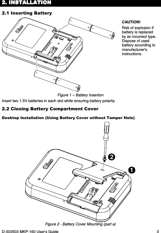
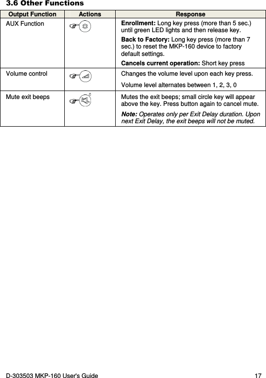
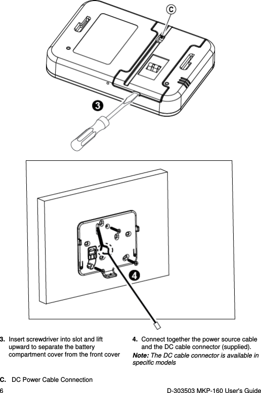
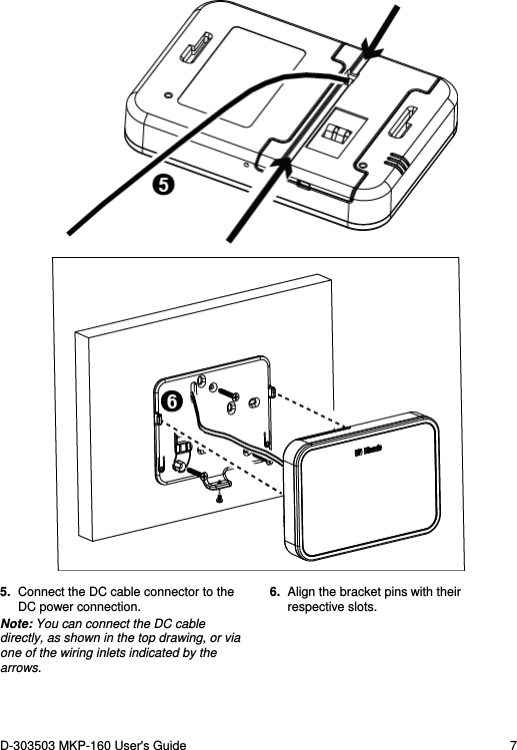
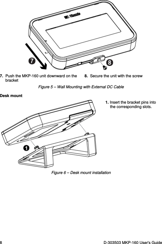
![4 D-303503 MKP-160 User's Guide Wall-mounted Installation [Via Battery Cover without Tamper Hole (see "A")] Figure 3 - Battery Cover Mounting (part b) A. Tamper B. DC Power Connection – use supplied cable in addition to batteries C. Wiring channel for wall installation Note: The DC cable is available in specific models 2.3 Wall Mounting Options The MKP-160 unit mounting options are illustrated in the following drawings. Wall Mounting Figure 4 – Wall Mounting 1. Drill 3 mounting holes 3. Attach the unit to the bracket 2. Position the bracket and secure with 3 screws 4. Secure the unit with the screw A. Hole for DC power source cable installed in wall](https://usermanual.wiki/Visonic/MKP160/User-Guide-1667028-Page-4.png)
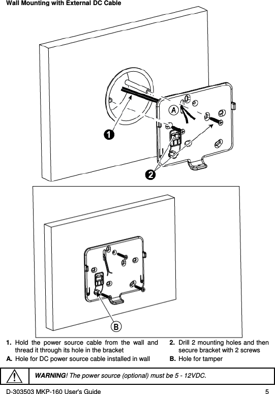
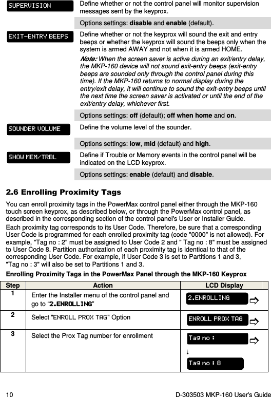
![12 D-303503 MKP-160 User's Guide 3333. USING THE . USING THE . USING THE . USING THE TOUCH SCREEN TOUCH SCREEN TOUCH SCREEN TOUCH SCREEN KEYPROXKEYPROXKEYPROXKEYPROX 3.1 Arming and Disarming the System Step Operation User Actions Keyboard & Panel Response Optional 1 Select a PARTITION (1) (if Partition is enabled) Any combination of The selected Partition blinks. 2 Arm AWAY (2) + [ ] (4) The selected key and the "Present Prox Tag" icon ( ) begin to blink and prompt you to present your Tag (except for Quick Arm). The keyprox's LED blinks red once to indicate transmission of the arming command to the control panel. The LED and the buzzer then indicate the control panel's response – see “System Status and Indications” section 3.3. Arm HOME (2) + [ ] (4) Disarm (OFF) (2) + [ ] (4) Quick arm AWAY (2) (3) (If Quick Arm is enabled) (≈ 2 sec.) Quick arm HOME (2) (3) (If Quick Arm is enabled) (≈ 2 sec.) Optional 3 INSTANT (After arming HOME/ AWAY) (5) (7) LATCHKEY (After arming AWAY) (6) (7) Notes: 1. If Partition is disabled at the control panel, skip Step 1. 2. If Partition is enabled at the control panel and a partition was not selected in Step 1, Step 2 will activate all of the partitions assigned to the user. 3. The Quick arm functions only if enabled at the control panel. 4. If the action is not completed while the selected arming key is blinking, the desired function will not be executed. 5. Press the INSTANT key within maximum 8 seconds timeout period after completing the previous step. This will delete the entry delay for the current arming session. • INSTANT is available only if supported in the PowerMax control panel (refer to the PowerMax Installer Guide). 6. For LATCHKEY activation, press the LATCHKEY key within maximum 8 seconds timeout period after completing the previous step.](https://usermanual.wiki/Visonic/MKP160/User-Guide-1667028-Page-12.png)
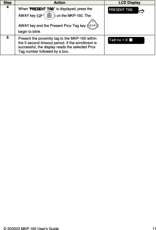
![14 D-303503 MKP-160 User's Guide Arming Indications The table below lists the Arming indication keys and their definition. Icon/Key Indications Arming Indication ARM AWAY ARM HOME DISARM (followed by) (followed by) EXIT DELAY + the "Present Prox Tag" icon and DISARM key blink simultaneously ENTRY DELAY If Partition is enabled, the corresponding (house) icon is displayed according to partition state. General Indications The Ready/Not Ready, Alarm Memory, Trouble and Low Battery indications are provided via the indications in the following table: Number Indication [1] What it Means Instructs the user to present the RFID proximity tag in order to initiate a command. Volume control mode. System is NOT READY; one of the zones is not secured. You cannot arm the system before the zone is secured or bypassed. System is READY but one or more zones are bypassed. No indication System is READY and all zones are secured. + Bypassed ( ) or Open ( ) Zone number / + Selected PGM or X-10 unit number. + Volume level](https://usermanual.wiki/Visonic/MKP160/User-Guide-1667028-Page-14.png)
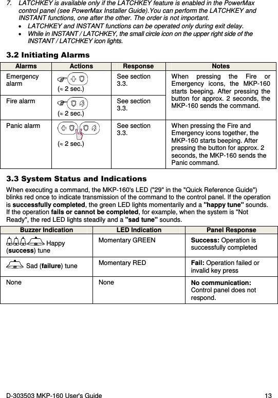
![D-303503 MKP-160 User's Guide 15 Number Indication [1] What it Means PGM/X-10 control mode. System is armed in LATCHKEY mode. Exit beeps are shut off. This mode disables when the exit delay is over. [2] System is armed in the INSTANT mode. A message is waiting in the system. The control panel is presently in "INSTALLER MODE" or "USER SETTINGS". Memory / Alarm in partition or system. The partition / system has an active trouble status that needs to be reviewed and cleared. [3] AC failure. Communication failure: MKP-160 is out of range of the control panel or did not get an acknowledge signal of a command from the control panel. Indicates that the MKP-160 device's battery is low and must be replaced (see section 2.1). [1] The key indication is displayed after the first red LED blinks indicating the status request. [2] Operates only during Exit Delay. [3] See respective sections in the control panel's User and Installer's Guides. [4] If there is more than one status indication at a single time, the keys are displayed simultaneously. Zone Status Indications To view the zone numbers of enrolled detectors that are in NOT READY ( ) or BYPASSED state ( ), repeatedly press the key. Upon each press of the key, the next zone number appears on the Zone # display (marked "4" in the "Quick Reference Guide"). To view the zone numbers that are assigned to a Partition, press the desired Partition number ( / / ) followed by the key. Upon each press of the key, the next zone number assigned to the pressed Partition number appears on the Zone # display.](https://usermanual.wiki/Visonic/MKP160/User-Guide-1667028-Page-15.png)
![16 D-303503 MKP-160 User's Guide Notes: A zone which is BYPASSED and NOT READY is shown as BYPASSED ( ). When "00" appears on the Zone # display, this indicates a NOT READY state in the alarm system that is not related to any detector, for example, "tamper open" in a keypad or control panel. If all zones are READY and "not bypassed", the button is disabled. 3.4 Bypassing Zones A zone can by bypassed by pressing the key until the zone number is shown on the zone # display (marked "4" in the "Quick Reference Guide") followed by the key. Note: Zone bypassing on the MKP-160 unit can be operated only if Bypass was enabled via the control panel (see PowerMax Installer Guide). 3.5 Controlling Home Automation Devices To operate home automation devices, see the table below. Note: Make sure that the relevant PGM and X-10 outputs are configured correctly; refer to the “OUTPUTS” menu in the control panel’s Installer Guide. Step X-10 device ON PGM device ON X-10 or PGM device OFF X-10 or PGM device TOGGLE 1 (~2sec) 2 … [1 to 15] … [P0] [PGM P0] or [X-10 1 to 15] [PGM P0] or [X-10 1 to 15] 3 The keyprox's LED blinks red once to indicate transmission of the command to the control panel. The LED and the buzzer then indicate the control panel's response – see “System Status and Indications” in section 3.3. Note: • Long press (more than 2 sec.) of the button initiates the X-10 function and the PGM/X-10 display (marked "4" in the "Quick Reference Guide") will read "01". This number is incremented by 1 upon each press of the key. • Short press of the button initiates the PGM function and the PGM/X-10 display will read "P0" with the key.](https://usermanual.wiki/Visonic/MKP160/User-Guide-1667028-Page-16.png)