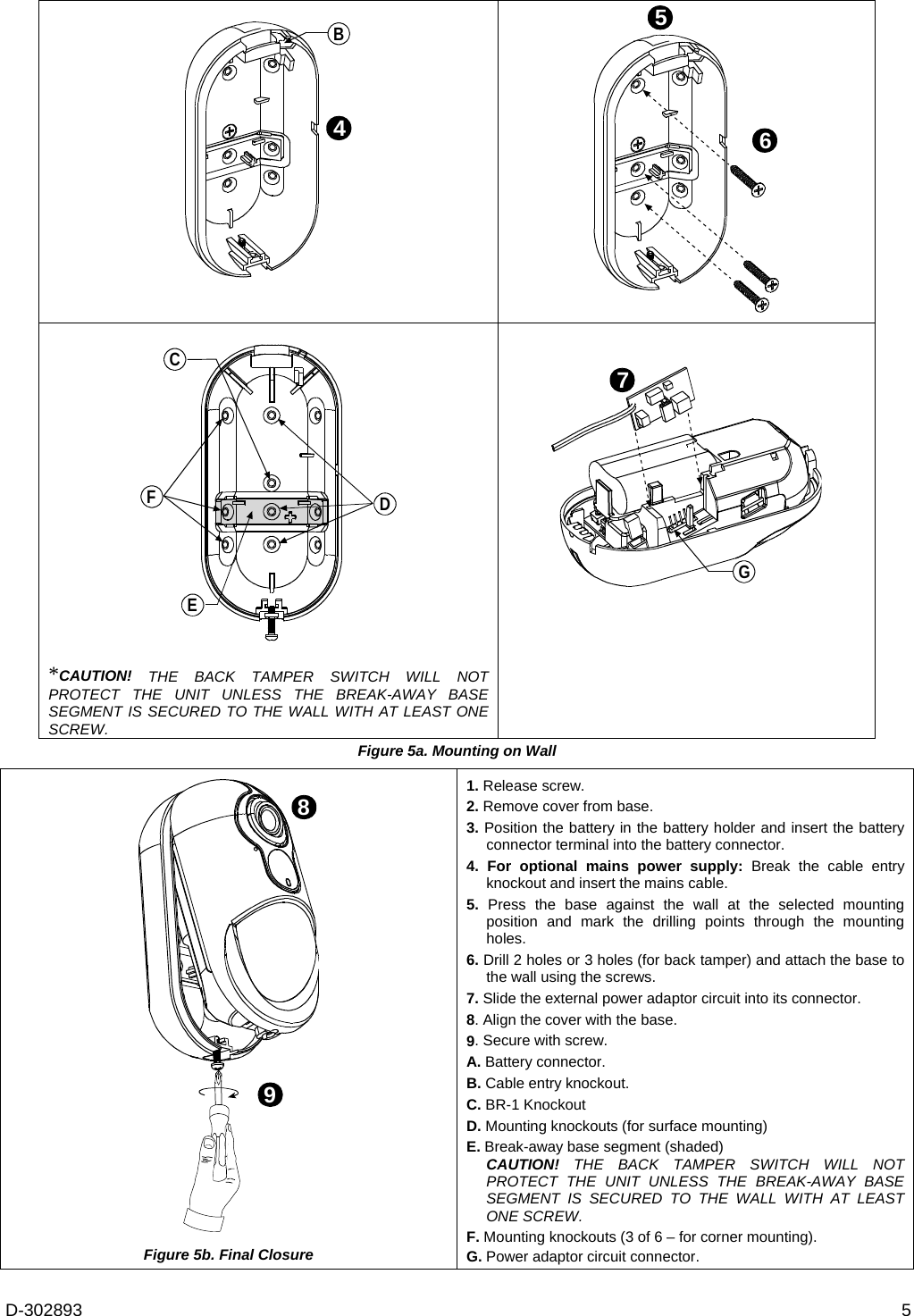
Visonic NEXTCAMPG2 Wireless digital PIR detector with camera User Manual User manual 21026
Visonic Ltd. Wireless digital PIR detector with camera User manual 21026
UserManual.wiki
>
Visonic
>
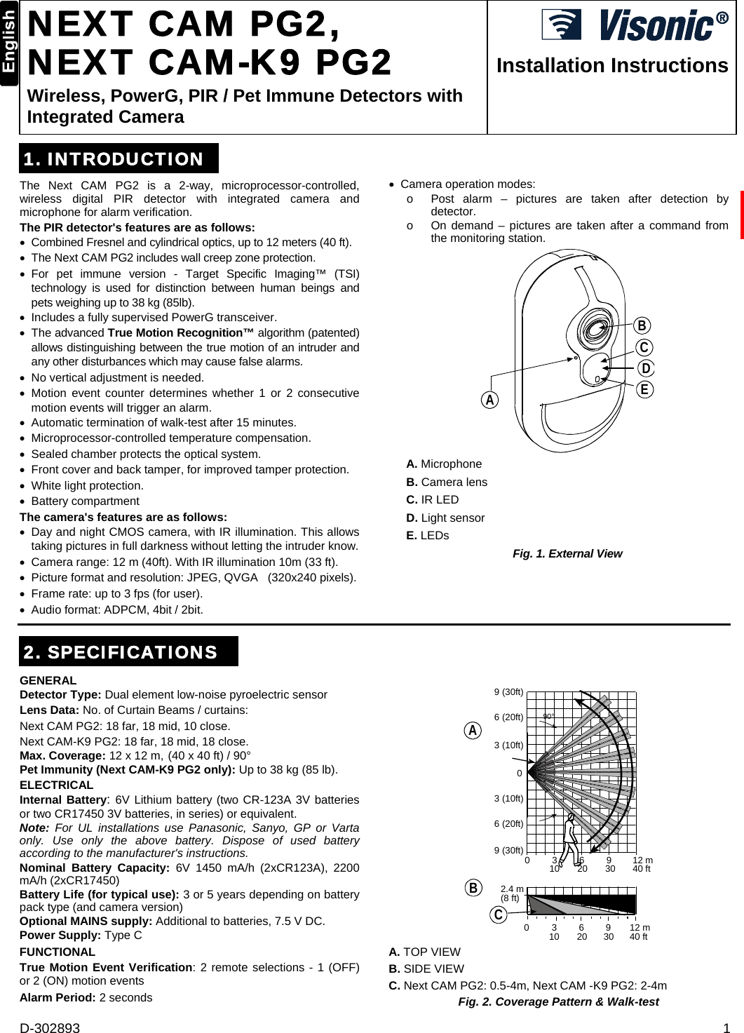
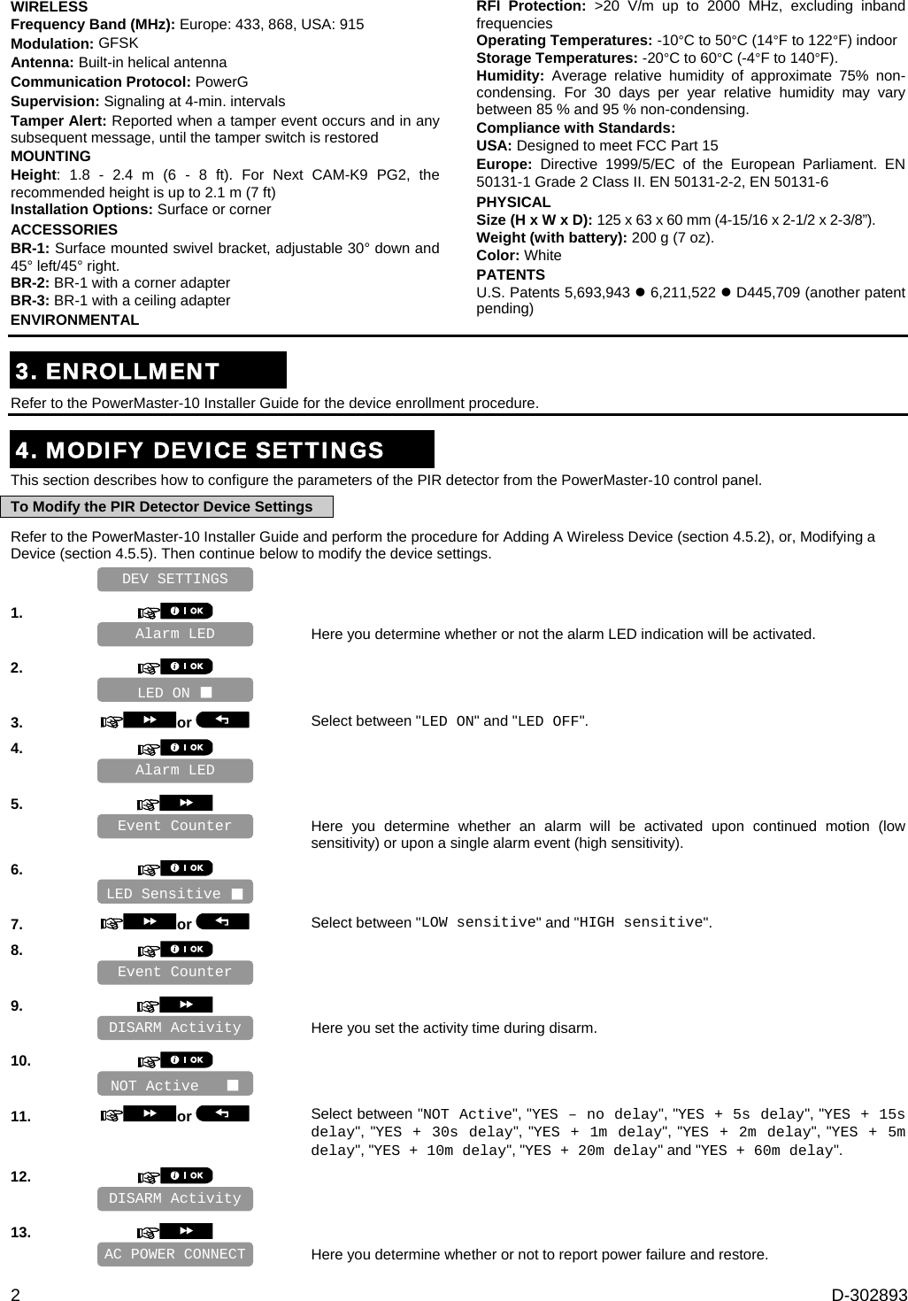
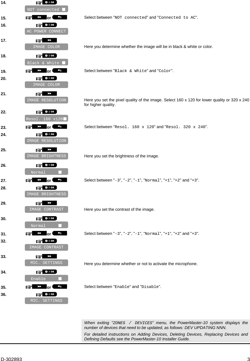
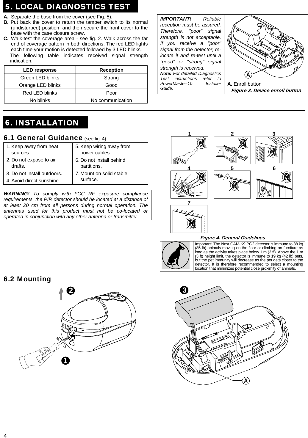
NEXTCAMPG2 User Manual
manual
Navigation menu
Upload a User Manual
Namespaces
Wiki Guide
HTML
PDF
Info
Views
User Manual
Discussion / Help
Navigation