Visonic NEXTDUO Microwave/PIR Motion Sensor User Manual
Visonic Inc. Microwave/PIR Motion Sensor Users Manual
Visonic >
Users Manual
DE1834 1
NEXT DUO
Dual-Technology, Digital MW/PIR Intrusion Detector
Installation Instructions
1. INTRODUCTION
The NEXT DUO is a digital, microprocessor-controlled MW / PIR
detector that can be adapted to the size of the protected area by
use of a model selector. A different digital signal processing (DSP)
is used upon selection of each model, thus optimizing both PIR and
MW performance within the protected area.
The PIR section of the NEXT DUO employs a cylindrical lens with
uniform detection sensitivity beginning at 0.5 m (1.8 ft) away from
the detector up to a distance of 12 meters (40 ft). Advanced True
Motion Recognition™ algorithm (patented) allows the NEXT
DUO to distinguish between the true motion of an intruder and
any other disturbances which cause false alarms.
A Test input permits switching the detector to the walk test mode
remotely without removing the front cover. An on-board motion
event jumper determines whether 1 or 2 consecutive motion
events would trigger an alarm.
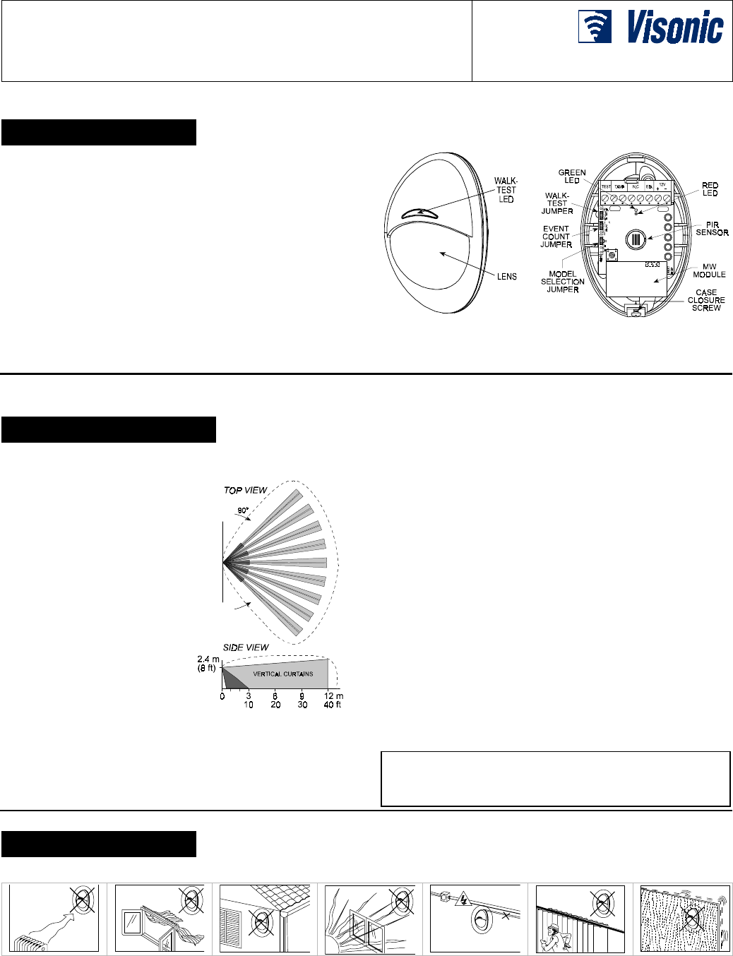
Figure 1. General View
Figure 2. Inside View
2. SPECIFICATIONS
Selectable Models: Models covering 6, 9 and 12 meters (20, 30
and 40 ft), selected upon installation
Input Voltage: 9 to 16 VDC
Current Drain: About 20 mA @
12 VDC
PIR SECTION (see Figure 3)
Lens Data
No. of Curtain Beams: 9 + 5
Max. Coverage: 12 x 12 m
(40 x 40 ft) / 90°
Tripping Indication: Indicator
lights ORANGE for about 3 sec.
MW SECTION
Oscillator Type: Microstrip,
DRO-stabilized
Frequency: 2.45 GHz
Detection Range: Up to 12 m
Tripping Indication: Indicator
lights GREEN for about 3 sec.
Figure 3. Maximum
Coverage Pattern
ALARM and TAMPER
Alarm Output: Solid-state relay, N.C., up to 100 mA / 30 V, ~30 Ω
internal resistance. Circuit opens for 2-3 seconds upon alarm.
Alarm Indication: Indicator lights RED for about 3 seconds.
Event Counter: Selectable, 1 or 2 motion events
Tamper Contacts: Normally closed, 50 mA resistive / 30 VDC
MOUNTING
Surface or corner, at the height of 1.8 to 2.4 m (6 to 8 ft)
Note: Base allows single-sided corner mount at 45° to wall.
ACCESSORIES:
BR-1: Surface mounted swivel bracket, adjustable 30° down and
45° left/45° right.
BR-2: BR-1 with a corner adapter
BR-3: BR-1 with a ceiling adapter
ENVIRONMENTAL
Operating Temperature: –10°C to 50°C (14°F to 122°F)
Storage Temperature: –20°C to 60°C (–4°F to 140°F)
RFI Protection: Greater than 20 V/m (20 MHz to 1000 MHz)
PHYSICAL
Size (H x W x D): 94.5 x 63.5 x 49.0 mm (3-11/16 x 2-1/2 x 1-15/16”)
Weight: Approximately 50 g (1-3/4 oz)
PATENTS
U.S. Patents 5,693,943 and 6,211,522 (another patent pending)
This device complies with the essential requirements and provisions
of Directive 1999/5/EC of the European Parliament and of the Council
of 9 March 1999 on radio and telecommunications terminal equipment.
2.45 GHz has no restriction in any EU member state.
3. INSTALLATION
3.1 General Guidelines
A. Microwave radiation passes through glass and non-metallic
walls. Be sure, therefore, to select the correct model in
accordance with the room size. This is important to minimize
the effect of movements occurring beyond room limits which
might cause the MW section to trip.
B. Large reflecting objects (especially metals) in the coverage
area can distort the microwave detector's coverage pattern.
C. If two NEXT-DUO units are installed in the same room or on
opposite sides of a shared wall, they should not face each
other and must be mounted at least 20 cm (0.6 ft) apart.
Attention! At power up, the detector undergoes a 60-second
stabilization period, indicated by alternate flashing of the red
and green LEDs.
2 DE1834
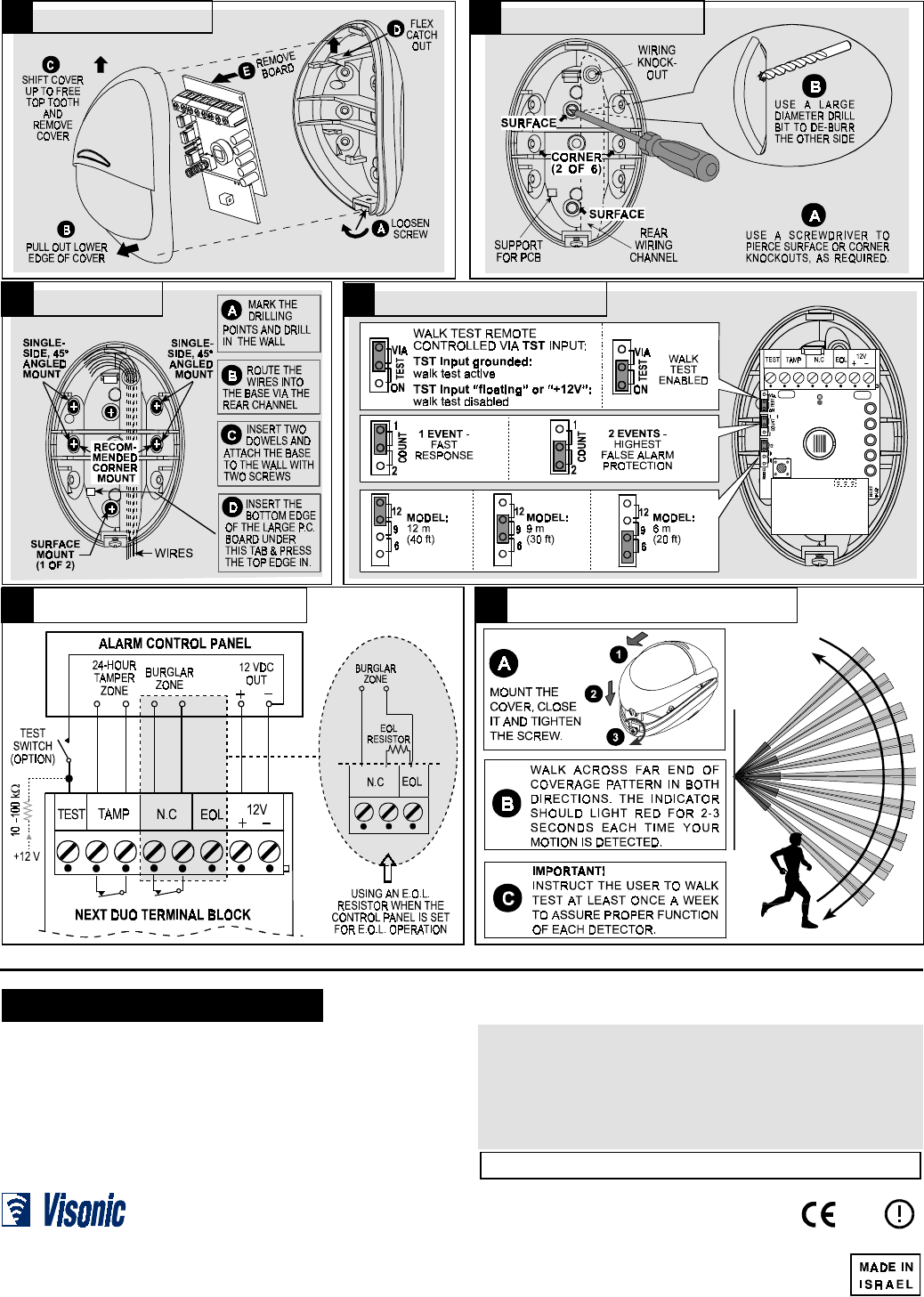
3.2 Illustrated Installation Procedure
4. SPECIAL COMMENTS
Even the most sophisticated detectors can sometimes be defeated or may fail to
warn due to: DC power failure / improper connection, malicious masking of the lens,
tampering with the optical system, decreased sensitivity in ambient tempera- tures
near that of the human body and unexpected failure of a component part.
The above list includes the most common reasons for failure to detect intrusion,
but is by no means comprehensive. It is therefore recommended that the
detector and the entire alarm system be checked weekly, to ensure proper
performance.
An alarm system should not be regarded as a substitute for insurance. Home
and property owners or renters should be prudent enough to continue insuring
their lives and property, even though they are protected by an alarm system.
This device has been tested and found to comply with the limits for a Class B digital device,
pursuant to Part 15 of the FCC Rules. These limits are designed to provide reasonable protection
against harmful interference in residential installations. This equipment generates, uses and can
radiate radio frequency energy and, if not installed and used in accordance with the instructions,
may cause harmful interference to radio and television reception. However, there is no guarantee
that interference will not occur in a particular installation. If this device does cause such interference,
which can be verified by turning the device off and on, the user is encouraged to eliminate the
interference by one or more of the following measures:
– Re-orient or re-locate the receiving antenna.
– Increase the distance between the device and the receiver.
– Connect the device to an outlet on a circuit different from the one that supplies power to the receiver.
– Consult the dealer or an experienced radio/TV technician.
WARNING! Changes or modifications to this unit not expressly approved by the party
responsible for compliance could void the user’s authority to operate the equipment.
VISONIC LTD. (ISRAEL): P.O.B 22020 TEL-AVIV 61220 ISRAEL. PHONE: (972-3) 645-6789, FAX: (972-3) 645-6788
VISONIC INC. (U.S.A.): 10 NORTHWOOD DRIVE, BLOOMFIELD CT. 06002-1911. PHONE: (860) 243-0833, (800) 223-0020 FAX: (860) 242-8094
VISONIC LTD. (UK): UNIT 1, STRATTON PARK, DUNTON LANE BIGGLESWADE, BEDS. SG18 8QS. PHONE: (01767) 600857 FAX: (01767) 601098
INTERNET: www.visonic.com
VISONIC LTD. 2001 NEXT DUO DE1834- (REV. 1, 12/01) Refer to separate warranty statement
0122
1 2
4
3
6 5
Set jumpers as needed
1.8 - 2.4 m (6 - 8 ft) above ground
Open holes in base
Disassemble unit
Mount base
Walk-test the coverage area
Wire up the terminal block