Users Manual
DE3591
1
NEXT MCW
Wireless PowerCode Digital PIR Detector
Installation Instructions
1. INTRODUCTION
The NEXT MCW is a microprocessor-controlled wireless digital
PIR detector, designed for easy installation, free of vertical
adjustment. It features a cylindrical lens with uniform detection
sensitivity throughout its operating range, up to 12 meters (40 ft),
with wall creep zone protection.
The advanced True Motion Recognition™ algorithm
(patented) allows the NEXT MCW to distinguish between the true
motion of an intruder and any other disturbances which may
cause false alarms.
An on-board motion event jumper determines whether 1 or 2
consecutive motion events triggers an alarm.
The NEXT MCW includes the following features:
• Incorporates a fully supervised PowerCode transmitter
• Patented sophisticated motion analysis algorithm - True Motion
Recognition (TMR™)
• Sophisticated frequency domain digital signal processing
• No vertical adjustment is needed
• Programmable motion event counter
• After detection, the detector disarms itself to save battery
power. It rearms (reverts to the ready state) if there is no
subsequent detection throughout the following 2-minute period
• Very low current consumption
• Microprocessor-controlled temperature compensation
• Sealed chamber protects the optical system
• Front cover tamper switch.
• Back tamper switch (option)
• White light protection
• Elegantly styled, sturdy case
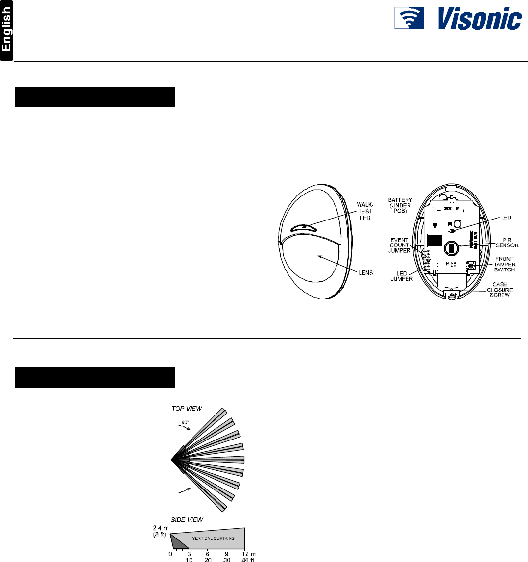
Figure 1. General View
Figure 2. Inside View
2. SPECIFICATIONS
OPTICAL
Detector Type: Dual element
low-noise pyroelectric sensor.
Lens Data
No. of Curtain Beams: 9 + 5
Max. Coverage: 12 x 12 m
(40 x 40 ft) / 90°
ELECTRICAL
Internal Battery: 3 V Lithium
battery, Panasonic CR-123 or
equivalent.
Nominal Battery Capacity:
1450 mA/h.
Standby Current Drain: approx.
0.025 mA.
Transmit Current Drain: 20 mA
(including LED).
Battery Life (with LED on):
Typically over 3 years.
Figure 3. Maximum
Coverage Pattern
Battery Power Test: Performed immediately upon battery
insertion and periodically after every several hours.
FUNCTIONAL
True Motion Event Verification: 2 position selector - 1 (OFF)
or 2 (ON) motion events.
Alarm Period: 3 seconds.
Visual Indications:
LED Lights for about 3 seconds upon transmission of alarm &
tamper messages and upon motion detection in the walk test
mode.
LED Flashes during the power-up stabilization period, or after
restoring (pressing) the tamper switch.
LED Does not light upon transmission of supervision
messages.
Rearm Timer: Rearms the detector 2 minutes after the last
alarm. Timer disabled in the walk test mode.
WIRELESS
Frequency (MHz): 315, 433.92, 868.95, 869.2625 or other
frequencies according to local requirements.
Transmission Sequence: 3 data bursts at variable intervals
within 3 seconds.
Encoding: 24-bit ID, over 16 million possible combinations.
Total Message Length: 36 bits.
Tamper Alert: Reported when a tamper event occurs and in any
subsequent message, until the tamper switch is restored.
Supervision Message: Signaling at 60-minute intervals (U.S.
version) or 15 minute interval (UK version), or according to the
local standards.
MOUNTING
Height: 1.8 - 2.4 m (6 - 8 ft).
Installation Options: Surface or corner.
ACCESSORIES:
BR-1: Surface mounted swivel bracket, adjustable 30° down and
45° left/45° right.
BR-2: BR-1 with a corner adapter
BR-3: BR-1 with a ceiling adapter
ENVIRONMENTAL
RFI Protection: >20 V/m up to 1000 MHz.
Operating Temperatures: -10°C to 50°C (14°F to 122°F).
Storage Temperatures: -20°C to 60°C (-4°F to 140°F).
Compliance with Standards: Designed to meet FCC Part 15
and Directive 1999/5/EC of the European Parliament.
PHYSICAL
Size (H x W x D): 94.5 x 63.5 x 53.0 mm (3-11/16 x 2-1/2 x 2-
1/16”).
Weight (with battery): 70 g (2.5 oz).
Color: White.
PATENTS: U.S. Patents 5,693,943 l 6,211,522 l D445,709
(another patent pending).
2
DE3591
3. INSTALLATION
3.1 General Guidelines
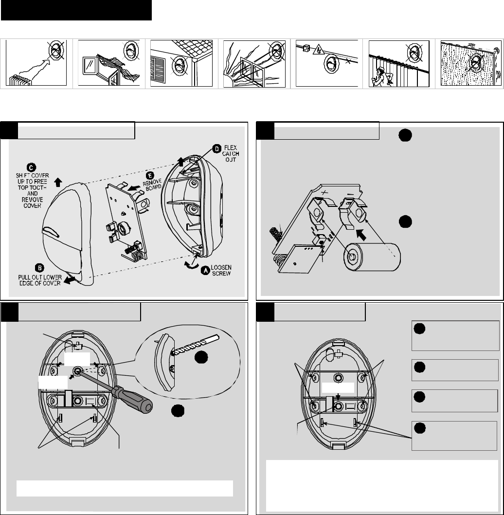
3.2 Illustrated Installation Procedure
RESET: With the battery in
place, press both tamper
switches simultaneously
and release them. The
LED at the front will flash
for about 2 minutes until
the detector sta bilizes.
Note: The de]tector transmits
a low battery signal upon
detection of low battery.
Note: It is recommended to wait
about 1 minute before inserting
the new battery.
A
B
BACK
TAMPER
SWITCH
(OPTION)
FRONT
TAMPER
SWITCH
OBSERVE
POLARITY !
ENROLL: Approach the
control panel and enroll the
detector’s ID into the control
panel’s memory as shown in
the panel’s installation
manual. When required to
transmit, press both tamper
switches again and release
them.
You may enroll the detector’s
ID while the detector’s LED
flashes.
USE A SCREWDRIVER TO PIERCE
SURFACE OR CORNER KNOCK-
OUTS, AS REQUIRED.
A
USE A LARGE
DIAMETER DRILL
BIT TO DE-BURR
THE OTHER SIDE
B
SUPPORTS
FOR BOTTOM
EDGE OF PCB
CORNER
(2 OF 4)
SURFACE
(1 OF 2)
BREAK-AWAY
SEGMENT (BACK TAMPER
SWITCH ACTUATOR - OPTION)
TOP
CATCH
FOR PCB
Attention! Lean the rear part of the break-away segment against a
piece of wood while piercing its knockouts.
B
INSERT TWO DOWELS AND
C
INSERT THE BOTTOM EDGE
D
MARK TWO DRILLING
A
SINGLE-
SIDE, 45°
ANGLED
MOUNT
SURFACE
MOUNT
(1 OF 2)
ATTACH THE BASE TO THE
WALL WITH TWO SCREWS.
OF THE LARGE P.C. BOARD
UNDER THE TABS & PRESS
THE TOP EDGE IN.
POINTS AND DRILL HOLES
IN WALL.
SINGLE-
SIDE, 45°
ANGLED
MOUNT
BREAK-AWAY
SEGMENT
FOR TAMPER PROTECTION,
THE BREAK-AWAY SEGMENT
MUST BE ATTACHED TO
WALL.
1.8 - 2.4 m (6 - 8 ft) above ground
Attention! The unit has a back tamper switch (option) under the PCB. As
long as the PCB is seated firmly within the base, the switch will be pressed
against a metal spring piece attached to the base.
Be sure to fasten the break-away segment to the wall with the screws
going through the metal spring and the break-away base segment. If
the detector is forcibly removed from the wall, this segment will break away
from the base, causing the tamper switch to open and send a tamper alarm.
1 2
3 4
Open holes in the
Disassemble the unit
Install the battery
Mount the base
DE3591
3
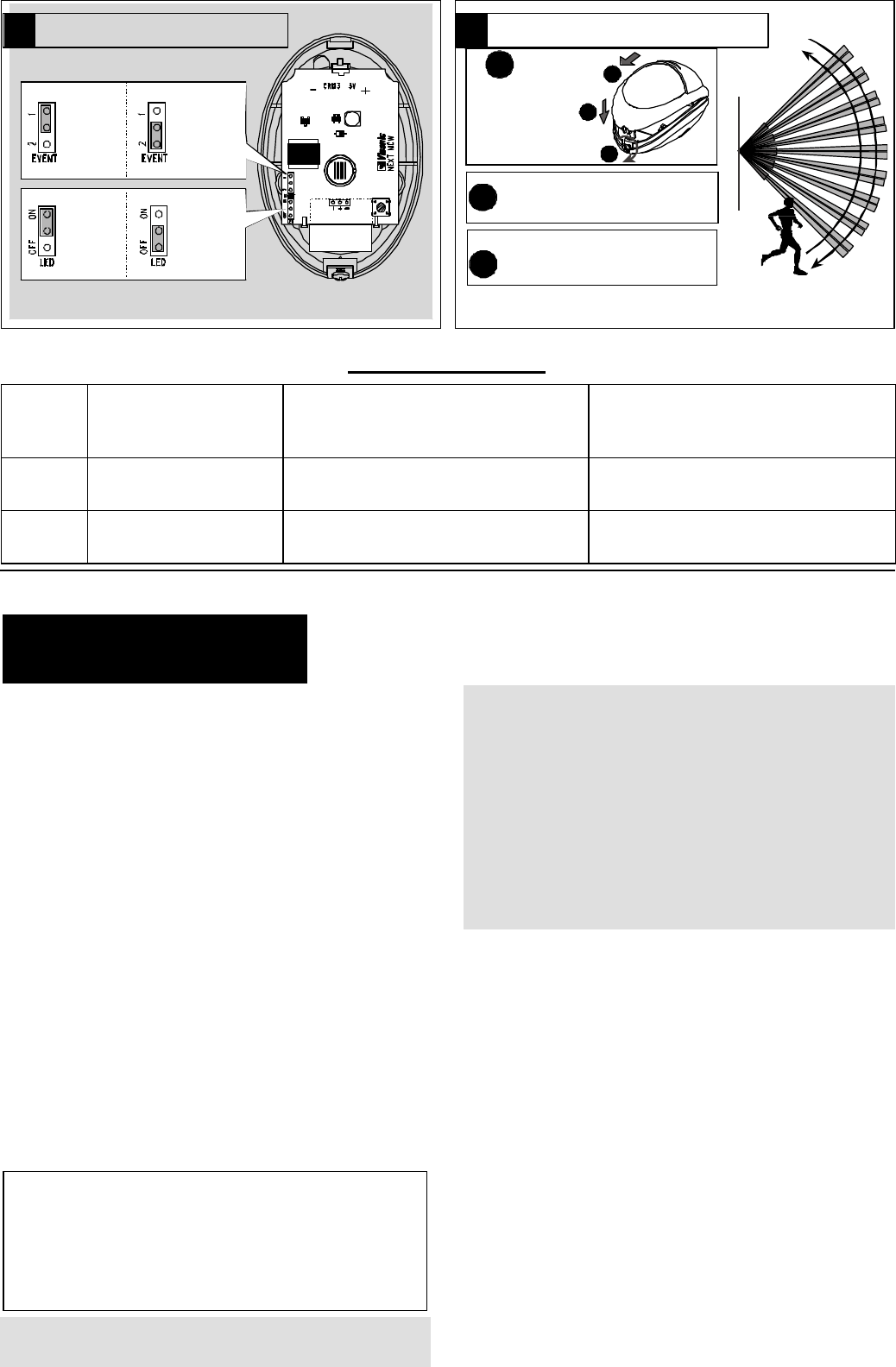
1 EVENT:
FAST
RESPONSE
2 EVENTS:
HIGHEST
FALSE
ALARM
PROTECTION
ON:
LED
ENABLED
OFF:
LED
DISABLED
IMPORTANT!
INSTRUCT THE USER TO WALK- TEST AT
LEAST ONCE A WEEK TO ASSURE PROPER
FUNCTION OF EACH DETECTOR.
BWALK ACROSS THE FAR END OF COVERAGE
PATTERN IN BOTH DIRECTIONS. THE
INDICATOR SHOULD LIGHT FOR 2-3 SECONDS
EACH TIME YOUR MOTION IS DETECTED.
C
A
MOUNT THE COVER,
CLOSE IT AND
TIGHTEN THE
SCREW.
WAIT FOR THE DETECTOR
TO STABILIZE (THE LED
STOPS FLASHING).
1
2
3
Note: After closing the cover the detector enters a 15 minute walk-test mode.
In this mode the LED will flash each time a detection occurs, regardless of LED
jumper settings, and the detector will transmit on the occurrence of each event.
LED Functions Summary
LED
Jumper
Position
First 2-3 Minutes After Closing
Cover Within 15 Minutes After Closing Cover - "Walk
Test Mode"
More than 15 Minutes After Closing Cover -
"Normal Mode"
ON LED Flashes LED lights and the unit sends RF alarm signal on
every detection LED lights, the unit sends RF alarm signal and
enters 2 minutes sleep mode.
OFF LED Flashes LED lights and the unit sends RF alarm signal on
every detection LED does not light! Unit sends RF alarm signal
and enters 2 minutes sleep mode.
4. SPECIAL
COMMENTS
4.1 Product Limitations
Visonic Ltd. wireless systems are very reliable and are tested to
high standards. However, due to their low transmitting power and
limited range (required by FCC and other regulatory authorities),
there are some limitations to be considered:
A. Receivers may be blocked by radio signals on or near their
operating frequencies, regardless of the code selected.
B. A receiver can only respond to one signal at a time.
C. Wireless equipment should be tested regularly to determine
whether there are sources of interference and to protect
against faults.
D. Even the most sophisticated detectors can sometimes be
defeated or may fail to warn due to: DC power failure /
improper connection, malicious masking of the lens,
tampering with the optical system, decreased sensitivity in
ambient temperatures near that of the human body and
unexpected failure of a component part.
The above list includes the most common reasons for failure
to detect intrusion, but is by no means comprehensive. It is
therefore recommended that the detector and the entire alarm
system be checked weekly, to ensure proper performance.
E. An alarm system should not be regarded as a substitute for
insurance. Home and property owners or renters should be
prudent enough to continue insuring their lives and property,
even though they are protected by an alarm system.
4.2 Compliance with Standards
The 315 MHz version of this device complies with Part 15 of the
FCC Rules. Operation is subject to the following two conditions:
(1) This device may not cause harmful interference, and (2)
This device must accept any interference received, including
interference that may cause undesired operation.
WARNING! Changes or modifications to this unit not
expressly approved by the party responsible for compliance
could void the user's authority to operate the equipment.
The digital circuit of this device has been tested and found to
comply with the limits for a Class B digital device, pursuant to Part
15 of the FCC Rules. These limits are designed to provide
reasonable protection against harmful interference in residential
installations. This equipment generates, uses and can radiate
radio frequency energy and, if not installed and used in
accordance with the instructions, may cause harmful interference
to radio and television reception. However, there is no guarantee
that interference will not occur in a particular installation. If this
device does cause such interference, which can be verified by
turning the device off and on, the user is encouraged to eliminate
the interference by one or more of the following measures:
– Re-orient or re-locate the receiving antenna.
– Increase the distance between the device and the receiver.
– Connect the device to an outlet on a circuit different from the
one which supplies power to the receiver.
– Consult the dealer or an experienced radio/TV technician.
4.3 Frequency Allocations for
Wireless Devices in European (EU)
Countries
• 315 MHz is not allowed in any EU member state.
• 433.92 MHz has no restriction in any EU member state.
• 868.95 MHz (wide band) is allowed in all EU member states.
• 869.2625 MHz (narrow band) is not restricted in any EU
member state.
6 5
Set the jumpers as
Walk
-
test the coverage area

4
DE3591
WARRANTY
Visonic Ltd. and/or its subsidiaries and its affiliates ("the Manufacturer") warrants its
products hereinafter referred to as "the Product" or "Products" to be in conformance
with its own plans and specifications and to be free of defects in materials and
workmanship under normal use and service for a period of twelve months from the
date of shipment by the Manufacturer. The Manufacturer's obligations shall be
limited within the warranty period, at its option, to repair or replace the product or
any part thereof. The Manufacturer shall not be responsible for dismantling and/or
reinstallation charges. To exercise the warranty the product must be returned to the
Manufacturer freight prepaid and insured.
This warranty does not apply in the following cases: improper installation, misuse,
failure to follow installation and operating instructions, alteration, abuse, accident or
tampering, and repair by anyone other than the Manufacturer.
This warranty is exclusive and expressly in lieu of all other warranties, obligations or
liabilities, whether written, oral, express or implied, including any warranty of
merchantability or fitness for a particular purpose, or otherwise. In no case shall the
Manufacturer be liable to anyone for any consequential or incidental damages for
breach of this warranty or any other warranties whatsoever, as aforesaid.
This warranty shall not be modified, varied or extended, and the Manufacturer does
not authorize any person to act on its behalf in the modification, variation or
extension of this warranty. This warranty shall apply to the Product only. All
products, accessories or attachments of others used in conjunction with the Product,
including batteries, shall be covered solely by their own warranty, if any. The
Manufacturer shall not be liable for any damage or loss whatsoever, whether directly,
indirectly, incidentally, consequentially or otherwise, caused by the malfunction of
the Product due to products, accessories, or attachments of others, including
batteries, used in conjunction with the Products.
The Manufacturer does not represent that its Product may not be compromised and/or
circumvented, or that the Product will prevent any death, personal and/or bodily
injury and/or damage to property resulting from burglary, robbery, fire or otherwise, or
that the Product will in all cases provide adequate warning or protection. User
understands that a properly installed and maintained alarm may only reduce the risk
of events such as burglary, robbery, and fire without warning, but it is not insurance
or a guarantee that such will not occur or that there will be no death, personal
damage and/or damage to property as a result.
The Manufacturer shall have no liability for any death, personal and/or bodily
injury and/or damage to property or other loss whether direct, indirect, incidental,
consequential or otherwise, based on a claim that the Product failed to function.
However, if the Manufacturer is held liable, whether directly or indirectly, for any loss
or damage arising under this limited warranty or otherwise, regardless of cause or
origin, the Manufacturer's maximum liability shall not in any case exceed the
purchase price of the Product, which shall be fixed as liquidated damages and not
as a penalty, and shall be the complete and exclusive remedy against the
Manufacturer.
Warning: The user should follow the installation and operation instructions and
among other things test the Product and the whole system at least once a week. For
various reasons, including, but not limited to, changes in environmental conditions,
electric or electronic disruptions and tampering, the Product may not perform as
expected. The user is advised to take all necessary precautions for his/her safety
and the protection of his/her property.
6/91
VISONIC LTD. (ISRAEL): P.O.B 22020 TEL-AVIV 61220 ISRAEL. PHONE: (972-3) 645-6789, FAX: (972-3) 645-6788
VISONIC INC. (U.S.A.): 10 NORTHWOOD DRIVE, BLOOMFIELD CT. 06002-1911. PHONE: (860) 243-0833, (800) 223-0020 FAX: (860) 242-8094
VISONIC LTD. (UK): FRASER ROAD, PRIORY BUSINESS PARK, BEDFORD MK44 3WH. PHONE: (0870) 730-0800 FAX: (0870) 730-0801
INTERNET: www.visonic.com
VISONIC LTD. 2003 NEXT MCW DE3591- (REV. 2, 06/03)