Visonic PMASTER360 Control panel of alarm system User Manual D 305736 PowerMaster 360 User s Guide
Visonic Ltd. Control panel of alarm system D 305736 PowerMaster 360 User s Guide
UserManual.wiki
>
Visonic
>
PMASTER360 User Manual
User manual
Navigation menu
Upload a User Manual
Namespaces
Wiki Guide
HTML
PDF
Info
Views
User Manual
Discussion / Help
Navigation

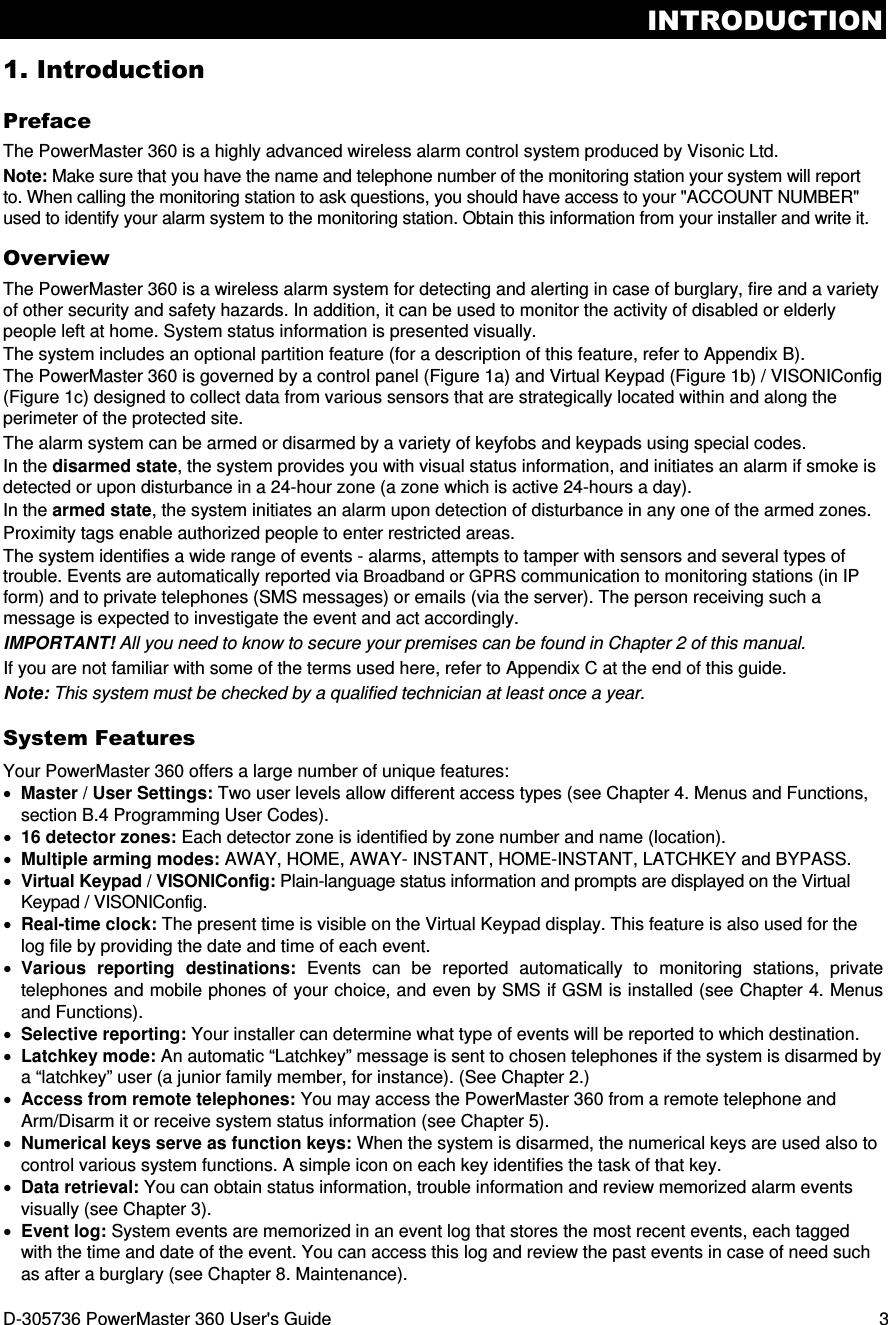
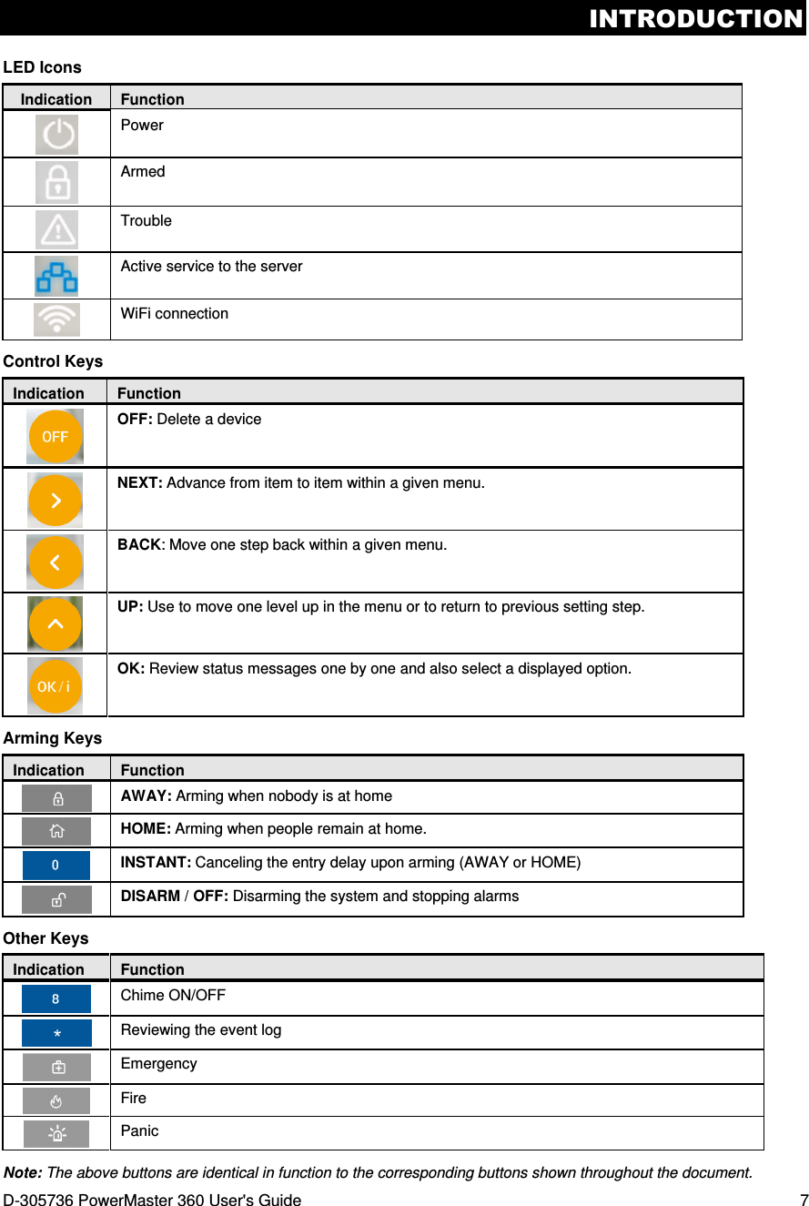
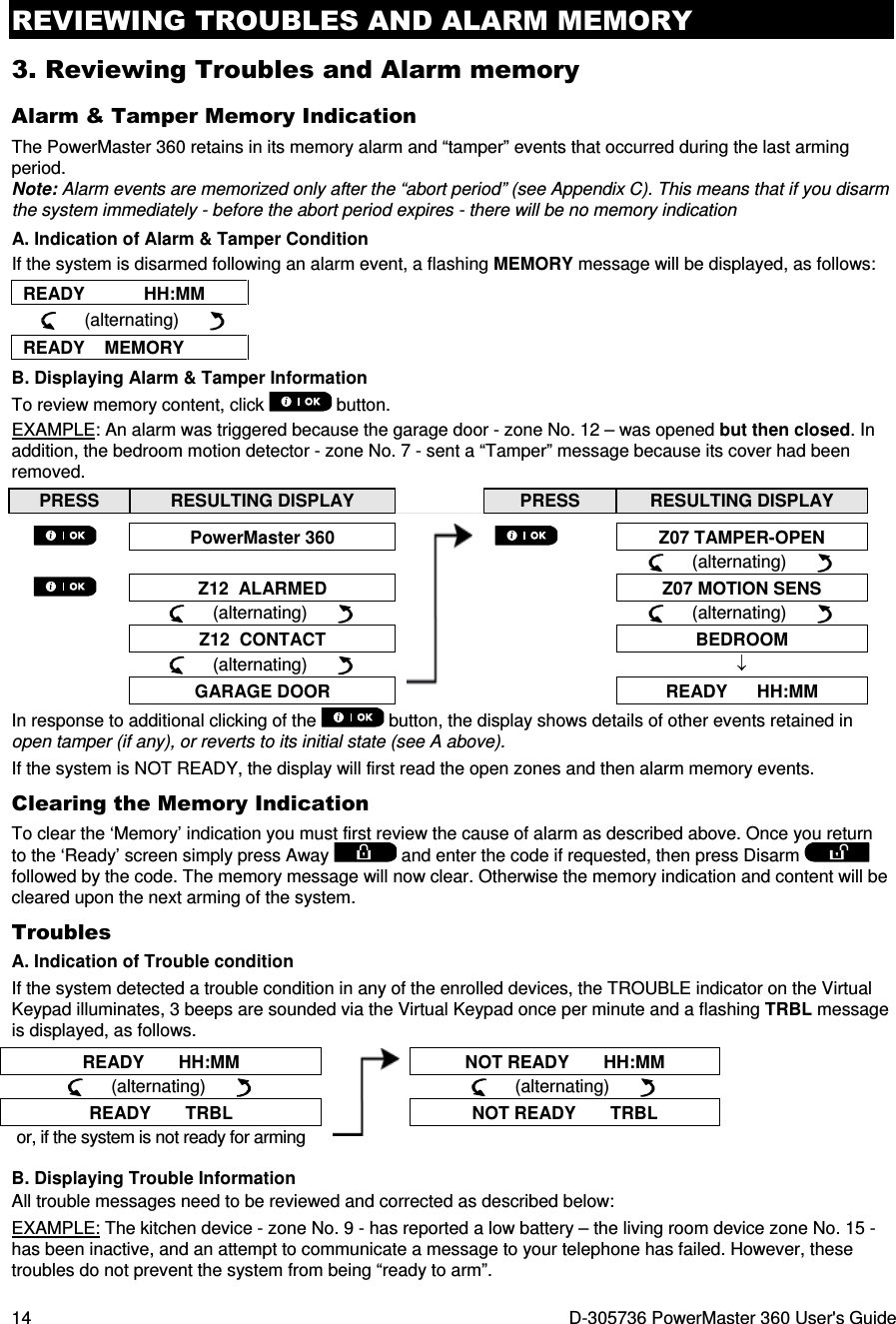
![ELECTRICAL APPLIANCE CONTROL 10 D-305736 PowerMaster 360 User's Guide After disarming, different displays may appear indicating that the system is in a state of alarm MEMORY. The MEMORY message will disappear only upon rearming the system. To disarm the system, proceed as shown: PRESS RESULTING DISPLAY ENTER CODE _ _ _ _ [Enter Code] / [Present tag] Code / Present tag READY HH:MM ARM indicator extinguishes during the disarmed state. Disarming the system also stops the siren alarm, irrespective of whether the alarm was initiated during the armed or the disarmed state. Disarming under Duress If you are forcibly compelled to disarm the system, enter the duress code (2580 by default) or another code set by the installer. Disarming will take place normally but a silent alarm will be transmitted to the monitoring station. Partition Selection Process Access to any desired partition is achieved through the use of an individual code or proximity tag. It is not possible to access the INSTALLER MODE menu if one or more partitions are in the AWAY or HOME modes. Before attempting to perform any operation on any given partition(s), it is necessary to perform the operations below which enable you to select the desired/allowed partition(s) using the individual code or proximity tag: PRESS RESULTING DISPLAY SELECT PARTITION Enter partition # (1 - 3) PARTITION 1 Note: The “Sad Tune” will be heard when selecting a partition to which no sensors / peripherals were enrolled. Special Arming & Disarming Options In addition to basic arming, PowerMaster 360 provides you with several advanced arming and disarming options: Switching from ‘HOME’ to ‘AWAY’ You do not have to disarm the system - just press . The response will be the same as in ARMING AWAY above. Vacate the premises before the exit delay expires. Switching from ‘AWAY’ to ‘HOME’ You do not have to disarm the system - just press . Since this operation reduces the security level, PowerMaster 360 will ask you to key in your master user code or user code, thus making sure that you are an authorized user. PRESS RESULTING DISPLAY ENTER CODE _ _ _ _ [Enter code] / [Present tag] Code / Present tag ARMING HOME Move to interior zone ↓ (Exit delay) ↓ ARM HOME HH:MM ARM indicator flashes during the armed state.](https://usermanual.wiki/Visonic/PMASTER360/User-Guide-2912169-Page-10.png)
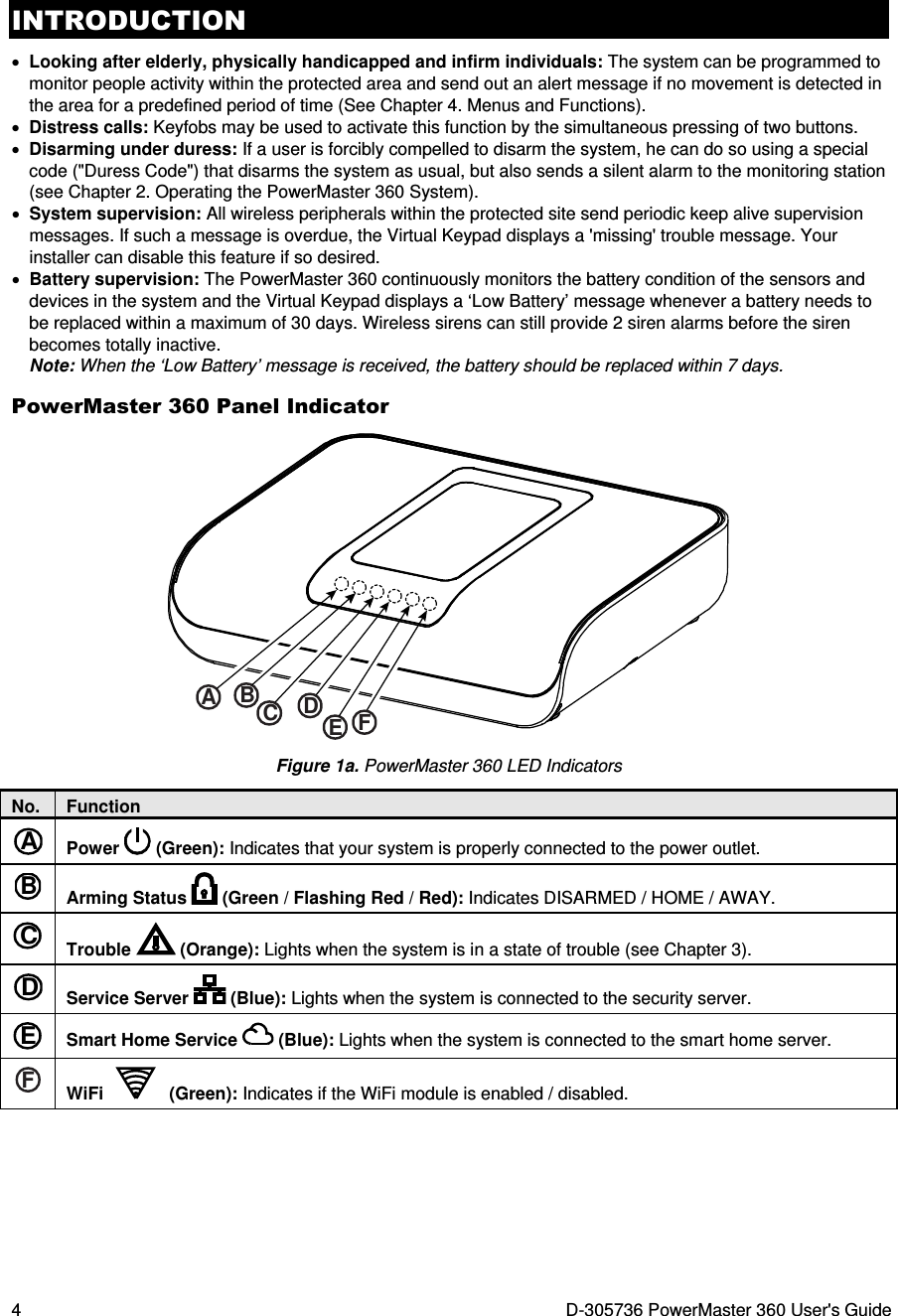
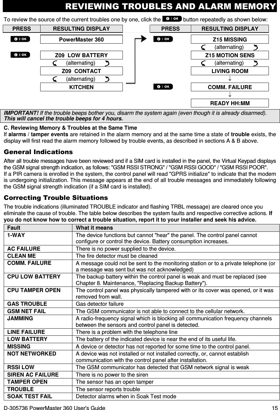
![ELECTRICAL APPLIANCE CONTROL D-305736 PowerMaster 360 User's Guide 11 Arming AWAY or HOME ‘Instant’ Pressing during the exit delay will arm the system in the "Instant' mode, i.e. without an entry delay. Therefore, any detection in any zone will trigger an immediate alarm. To arm AWAY-INSTANT, proceed as follows. PRESS RESULTING DISPLAY ENTER CODE _ _ _ _ Code ARMING AWAY ARMING INSTANT (alternating) PLEASE EXIT NOW Vacate the premises ↓ (Exit delay) ↓ AWAY ARM indicator lights during the armed state. Forced Arming AWAY or HOME Forced arming allows you to arm the system even if the system is "NOT READY". Any open zones will be bypassed for the duration of arming. Note: When forced arming is carried out, the buzzer “protests” by emitting a continuous tone during the exit delay until the last 10 seconds of the delay. You can silence this signal by pressing the arming button again. If forced arming is enabled and you wish to arm the system when NOT READY is displayed, proceed as shown: PRESS RESULTING DISPLAY ENTER CODE _ _ _ _ [Enter code] / [Present tag] Code / Present tag ARMING AWAY PLEASE EXIT NOW (to mute the buzzer) Vacate the premises ↓ (Exit delay) ↓ AWAY ARM indicator lights during the armed state. Remember: Forced arming compromises security!!](https://usermanual.wiki/Visonic/PMASTER360/User-Guide-2912169-Page-11.png)
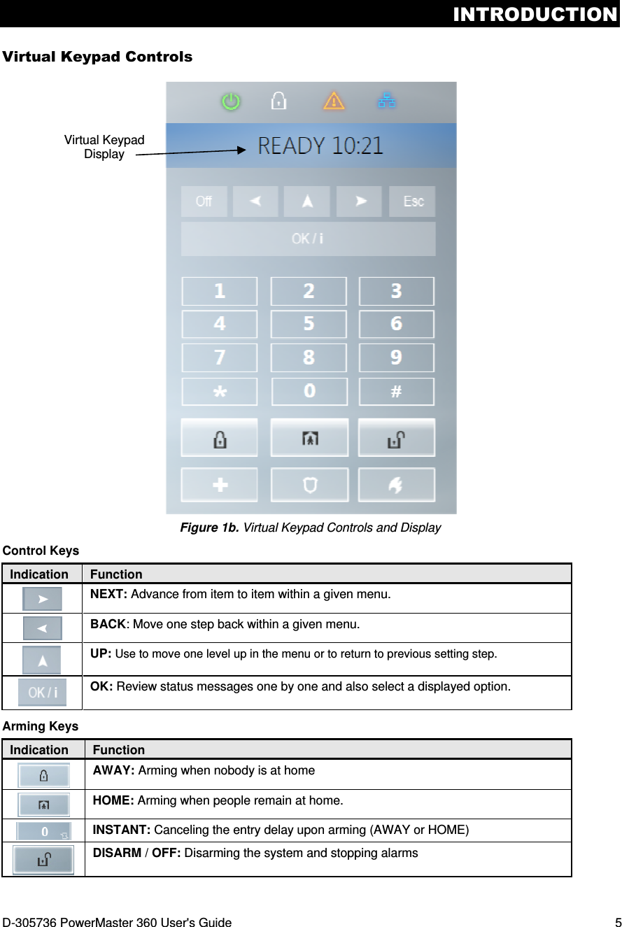
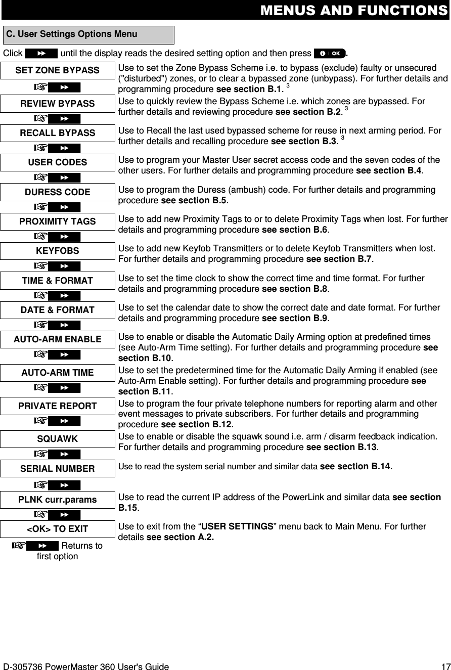
![ELECTRICAL APPLIANCE CONTROL 12 D-305736 PowerMaster 360 User's Guide Forced arming “HOME” is performed in a similar manner, as follows: PRESS RESULTING DISPLAY ENTER CODE _ _ _ _ [Enter code] / [Present tag] Code / Present tag ARMING HOME PLEASE EXIT NOW (to mute the buzzer) Go to interior zone ↓ (Exit delay) ↓ HOME HH:MM ARM indicator flashes during the armed state. Arming in the Latchkey Mode This mode, if enabled by the installer, is useful for a parent at work who wants to be sure that his children have returned from school and have disarmed the system. A special “latchkey” message will be sent out when the system is disarmed by a “latchkey user”. Latchkey users are holders of user codes or users of keyfob transmitters 5 through 8. The latchkey message is considered an alert and not an alarm, and is therefore sent to the private telephones programmed by the user as targets for alert messages. Latchkey arming is possible only when you arm “AWAY”. To arm in the Latchkey mode, proceed as follows: PRESS RESULTING DISPLAY ARMING AWAY ARMING LATCHKEY (Within 2 seconds) (alternating) PLEASE EXIT NOW Vacate the premises ↓ (Exit delay) ↓ AWAY Note: Latchkey must be enabled by your installer. ARM indicator lights during the armed state. Initiating Alarms Following are various methods that may be used for initiating alarms. Initiating Panic Alarm You can generate a panic alarm manually in the disarmed and armed states. The sequence will be as shown: PRESS RESULTING DISPLAY PANIC ALARM simultaneously READY HH:MM To stop the alarm, press the button and then key in your valid user code.](https://usermanual.wiki/Visonic/PMASTER360/User-Guide-2912169-Page-12.png)
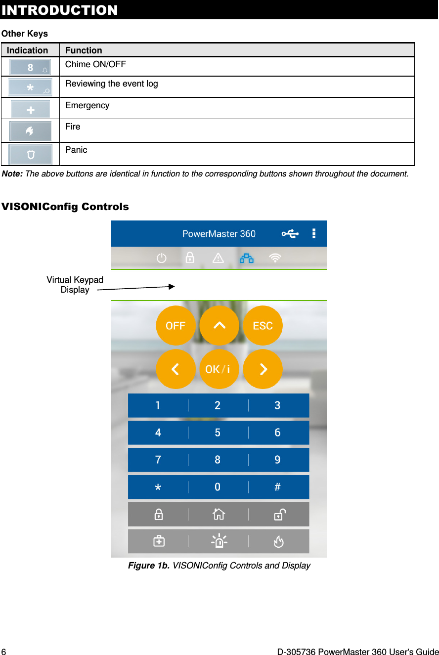
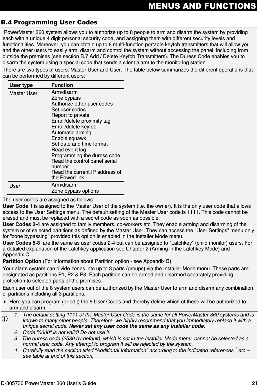
![MENUS AND FUNCTIONS 16 D-305736 PowerMaster 360 User's Guide 4. Menus and Functions This chapter explains the user programming features of your PowerMaster 360 system and allows you to tailor the PowerMaster 360 system according to your specific needs. All menu operations are performed using the Virtual Keypad / VISONIConfig which contains the alarm system’s control keys, numerical keypad and display. The chapter is divided into two sections, as follows: Part A – Guides you how to enter/exit the User Settings menu and how to select the desired setting options. Part B – Guides you to execute the selected settings. A.1 Entering the User Settings Menu & Selecting a Setting Option The following procedure describes how to enter and move within the User Settings menu. Detailed descriptions of the User Settings options are provided at the end of the procedure. To exit the User Settings menu – see section A.2. 1. You can enter the "USER SETTINGS" menu only when the system is disarmed. 2. Carefully read the section titled "Additional Information" according to the indicated references 1 etc – see table at end of this section. A. To Enter the USER SETTINGS Menu 1. READY 00:00 Make sure the system is disarmed and then press the button repeatedly until the display reads [USER SETTINGS]. 1 2. USER SETTINGS Press ENTER CODE: The screen will now prompt you to enter your user code or present your proximity tag. 3. CODE Enter your User Code. 2 SET BYPASS The display reads the first Setting option of the User Settings menu [SET BYPASS]. 3 B. To Select a Setting Option 4. SET BYPASS Click the or button until the display reads the desired setting option, for example, "TIME & FORMAT". or 5. TIME & FORMAT When the desired setting option appears on the display, press the button to enter the setting process. Continue to the selected setting option in B.1 - B.15 The remainder of the procedures for the selected setting options is provided in sections B.1 to B.15. Additional Information (section B.1) 1 Display shown in disarm state when all zones are secured (00:00 or other digits show present time). 2 a. If you have not already changed your personal code number, use the default setting – 1111. b. Master User has access to all User Settings options. Other users have access only to the Bypass options. c. If you enter an invalid user code 5 times, the keypad will be automatically disabled for a pre-defined period of time and the message WRONG PASSWORD will be displayed. 3 The bypass options will be displayed in the User Settings menu only if enabled by the installer. Otherwise, the first User Settings option displayed will be [USER CODES].](https://usermanual.wiki/Visonic/PMASTER360/User-Guide-2912169-Page-16.png)
![MENUS AND FUNCTIONS 18 D-305736 PowerMaster 360 User's Guide A.2 Returning to the Previous Step or Exiting the USER SETTINGS Menu During the setting process it is frequently necessary to return to the previous setting step or option (i.e. "to go one level up") or to exit the User Settings menu. A. To Move One Level Up To move one level up during the setting process, click once or more. Each click will take you one level up or to the previous setting step: B. To Exit the USER SETTINGS Menu Any screen To exit [USER SETTINGS], move up the menu by pressing repeatedly (see above) until the display reads [<OK> TO EXIT], or preferably, press once which brings you immediately to the exit screen [<OK> TO EXIT]. or <OK> TO EXIT When the display reads [<OK> TO EXIT], press READY 12:00 The system exits the [USER SETTINGS] menu and returns to the normal disarm state while showing the READY display. A.3 Buttons used for Navigation & Setting The keypad's buttons are used for various functions when programming. The following table provides a detailed description of the function or use of each button. Button Definition Navigation / Setting Function NEXT Use to move / scroll forward to the next menu options. BACK Use to move / scroll backward to the previous menu options. UP Use to move one level up in the menu or to return to previous setting step. OK Use to select a menu option or to confirm a setting or action. HOME Use to move one level up in the menu or to return to previous setting step. AWAY Use to jump back to the [<OK> TO EXIT] screen to quit programming. OFF Use to cancel, delete, clear or erase setting, data, etc. 0 - 9 Numerical keypad used to enter numerical data. B.1 Setting the Zone Bypass Scheme Bypassing permits arming only part of the system while allowing free movement of people within certain zones when the system is armed. It is also used to temporarily remove from service faulty zones that require repair work or to deactivate a sensor if, for example, you are decorating a room. ♦ Here you can set the Zone Bypass Scheme i.e. to scroll through the list of registered (enrolled) sensors to your PowerMaster 360 system and to Bypass (deactivate) faulty or disturbed sensors (either READY or NOT-READY) or to Clear (reactivate) BYPASSED zones (sensors). Once you have set a Bypass Scheme you can use the following 3 options: > To quickly review the bypassed zones – refer to section B.2. > To quickly clear a bypassed zone i.e. to reactivate the bypassed zone – refer to section B.1. > To repeat (recall) the last used zone bypassing scheme – refer to section B.3.](https://usermanual.wiki/Visonic/PMASTER360/User-Guide-2912169-Page-18.png)
![MENUS AND FUNCTIONS D-305736 PowerMaster 360 User's Guide 19 1. Zones will be bypassed throughout one disarm-arm period only. Disarming the system after arming will suspend the entire bypassing scheme but you can recall and reuse it as described in section B.3. 2. Fire zones cannot be bypassed. 3. Carefully read the section titled "Additional Information" according to the indicated references 1 etc – see table at end of section B.3. REMEMBER – ZONE BYPASSING COMPROMISES SECURITY! A. To Bypass a Zone 1. SET ZONE BYPASS Enter the [USER SETTINGS] menu1, select the [SET ZONE BYPASS]2 option and press . Z01: READY The first zone, Z01, is displayed. 3 Z01: P1 P2 P3 4 Living Room 2. or Click the or button until the display reads the zone you wish to bypass (or clear bypass), for example, "Z04" for Zone 04. After several seconds the LED on the respective device starts flashing indicating "it's me". Z04: NOT READY Z04: P1 P2 P3 4 3. Kitchen When the display reads the zone you wish to bypass press . 4. <OK> TO BYPASS The display now reads [<OK> TO BYPASS]. 5 To bypass the selected zone press 5. Z04: BYPASSED A "Happy Tune" ☺ sounds and the updated zone status is now displayed i.e. [Z04: BYPASSED]. 8 B. To Clear a Bypassed Zone 6. Z04: BYPASSED Repeat steps 1 to 2 above. Z04: P1 P2 P3 4 7. Kitchen When the zone you wish to clear bypass appears on the display (for example, "Z04"), press to confirm. You can also identify the device by looking for the "it's me" LED indication on the displayed device. <OFF> TO CLEAR The display now reads [<OFF> TO CLEAR]. 5 8. To clear the bypassed zone, press the button. Z04: READY A "Happy Tune" ☺ sounds and the updated zone status is now displayed, i.e. [Z04: READY] or [Z04: NOT READY]. 9](https://usermanual.wiki/Visonic/PMASTER360/User-Guide-2912169-Page-19.png)
![MENUS AND FUNCTIONS 20 D-305736 PowerMaster 360 User's Guide B.2 Reviewing the Zone Bypass Scheme ♦ Here you can quickly review the Bypass Scheme i.e. the zones that are set to be bypassed during the next arming session. 1. REVIEW BYPASS Enter the [USER SETTINGS] menu and select the [REVIEW BYPASS]1 option and press . 2 2. BYPASS LIST The display reads [BYPASS LIST] or Click the or buttons repeatedly to review all bypassed zones in ascending numerical order. When done, click to exit. 9 3. Z04: BYPASSED Z04: P1 P2 P3 4 Kitchen B.3 Recalling the Zone Bypass Scheme ♦ Use this option to repeat (recall) the most recent Bypassed Scheme for use during the next arming session. 1. RECALL BYPASS Enter the [USER SETTINGS] menu, select the [RECALL BYPASS] 1 option and press . 2, 6 2. <OK> TO RECALL The display now reads [<OK> TO RECALL]. 7 To recall the last used bypass scheme press . 3. Bypass RECALLED A "Happy Tune" ☺ sounds. The display reads [Bypass RECALLED] and then returns to “USER SETTINGS" step 1. 9 ☺ Return to step 1 Additional Information (section B.1 – B.3) 1 For detailed instructions on how to select User Settings –refer to sections A.1 and A.2. 2 This menu is displayed only if "BYPASS" was previously enabled by the installer. 3 a. The STATUS to the right of the zone number indicates whether the zone is READY, NOT-READY or BYPASSED. b. In the example, the display reads [Z01: READY] alternating with [Living Room]. 4 This display will appear only if PARTITIONING was previously enabled. 5 a. If the zone you selected is "not bypassed", the display prompts you to press [<OK> TO BYPASS]. However, if the zone you selected is already "bypassed", the display prompts you to press [<OFF> TO CLEAR]. b. To abort and return to the previous step press or 6 This menu is not displayed if Partition is enabled. 7 The display now prompts you to press [<OK> TO RECALL] i.e. to repeat the last used bypass scheme. To abort and return to the User Settings menu, press . 8 You can now repeat steps 2 - 5 to bypass or clear another zone. To end this session and to select other menu options or to quit programming - follow the instructions in section A.2. 9 You can now select another option in the User Settings menu (see section A.1), or quit programming (see section A.2).](https://usermanual.wiki/Visonic/PMASTER360/User-Guide-2912169-Page-20.png)
![MENUS AND FUNCTIONS 22 D-305736 PowerMaster 360 User's Guide A. To Program a User Code B. To Set Partitions Authorization* Additional Information (section B.4) 1 For detailed instructions on how to select the setting options – refer to sections A.1 and A.2. 2 The display shows the 1st User Code (Master User) in the list of 8 User Codes. If you have not yet changed the default code 1111, we recommend that you change it now. 3 a. The display shows the user code currently programmed in this location (e.g. 5327). b. The cursor blinks on the first digit of the code. c. If the location is free the display will be blank ( - - - - ). 4 You can move the cursor to the next or previous digit by pressing or . Pressing erases the digit of the cursor + all digits right of the cursor. 5 a. The new code is momentarily displayed without the cursor before reverting to step 3. b. If Partition is enabled, continue to step 6. 6 You can now repeat steps 3 - 5 to program or edit another user code. To end this session and to select other menu options or to quit programming – follow the instructions in section A.2. 7 This setting can be performed only after completing steps 1 - 5 of section B.4A. 8 The symbol now appears next to the newly selected Partitions. 9 You can now repeat steps 3 - 7 to program or edit another user code. * When PARTITIONING is enabled. 1. USER CODES Enter the [USER SETTINGS] menu, select the [USER CODES] option and press . 1 2. User 01 Code The first user code "User 01 Code" is displayed. 2 or At the blinking cursor position, key in the User Code you wish to program , for example, [06] for user code 6, or alternatively click the or button until the display reads, [User 06 Code]. 3. User 06 Code When the user code you wish to program appears on the display, press . 4. User 06 : 234 To program or edit the code, at the blinking cursor position enter the 4 digit code, for example, “1234”, using the numerical keypad. 3, 4 5. When done, press . User 06 : 1234 ☺ Return to step 3 A "Happy Tune" ☺ sounds. The display confirms the saved code. 5, 6 6. SET PARTITIONS The display will read [SET PARTITIONS]. 7 7. U06: P1 P2 P3 Use the keypad keys , , to change the status of the partitions P1, P2 & P3, respectively. 8 U06: P1 P2 P3 When you are satisfied with the setting, for example, User 6 is authorized with Partition 1 and 3 only, press to confirm. ☺ Return to step 3 A "Happy Tune" ☺ sounds. The display confirms the Partition setting. 9](https://usermanual.wiki/Visonic/PMASTER360/User-Guide-2912169-Page-22.png)
![MENUS AND FUNCTIONS D-305736 PowerMaster 360 User's Guide 23 B.5 Programming the Duress Code A. To Program the Duress Code Additional Information (section B.5) 1 For detailed instructions on how to select the setting options – refer to sections A.1 and A.2. 2 The display shows the default duress code (2580). 3 Do not set the duress code the same as an installer or user code. 4 To end this session and to select other menu options or to quit programming – follow the instructions in section A.2. B.6 Add / Delete Proximity Tags A proximity tag may be assigned to each of the user codes 1-8 that can be used instead of the user codes to perform a variety of functions, for example, arming, disarming, reading the event log, etc. Whenever a user code is required you can simply present a valid proximity tag instead of entering the user code. Each tag should be assigned with a serial No. 1-8 that corresponds to the User Code No. 1-8 and enrolled into the system correspondingly. The partition authorization of the tags is identical to their corresponding user codes. For example, proximity tag 3 is assigned to user code 3. ♦ Here you can add (enroll) new proximity tags or delete tags as required. Carefully read the section titled "Additional Information" according to the indicated references1 etc – see table at end of this section. A. To Add (Enroll) a Proximity Tag 1. PROXIMITY TAGS Enter the [USER SETTINGS] menu, select the [PROXIMITY TAGS] option and press . 1 2. ADD NEW TAG The display will read [ADD NEW TAG]. 3 To begin the process of enrolling a new proximity tag, press . 3. ENROLL NOW or ENTR ID:xxx-xxxx Present the proximity tag to the control panel within the timeout period. 4. DEVICE ENROLLED If enrollment was successfully completed, a "Happy Tune" ☺ sounds and the display reads [DEVICE ENROLLED] for a short duration and then changes to read the tag's details. 4 ☺ Go to step 5 5. T01:Tag (Prox) The display shows the allocated tag serial No (user No.), which is always the first free number, for example: [T01:Tag (Prox)]. A duress (ambush) alarm message can be sent to the Monitoring Station if you are forced to disarm the system under violence or menace. To initiate a duress message, you must disarm the system using a duress code (2580 by default). 1. DURESS CODE Enter the [USER SETTINGS] menu, select the [DURESS CODE] option and press . 1 2. DURESS CODE 2580 At the blinking cursor position, key in the Duress Code you wish to program, for example, 6973. 2, 3 3. DURESS CODE 6973 When the duress code you wish to program appears on the display, press . ☺ Return to step 1 A "Happy Tune" ☺ sounds. The display confirms the saved code.4](https://usermanual.wiki/Visonic/PMASTER360/User-Guide-2912169-Page-23.png)
![MENUS AND FUNCTIONS 24 D-305736 PowerMaster 360 User's Guide or To assign the tag to another user, for example, "User No. 5", key in [05] or alternatively click the or button until the display reads [T05:Tag (Prox)] and then press to confirm. T05:Tag (Prox) ☺ Return to step 2 The display reads [DEVICE ENROLLED] a "Happy Tune" ☺ sounds and the display will then change to [T01:Tag (Prox)]. 5 6 B. To Set Partitions Authorization∗∗∗∗ C. To Delete a Proximity Tag 1. PROXIMITY TAGS Enter the [USER SETTINGS] menu, select the [PROXIMITY TAGS] option and press . 1 2. ADD NEW TAG The display will read [ADD NEW TAG]. Click the button until the display reads [DELETE TAG]. 3. DELETE TAG Press . T01:Tag (Prox) The display will read [T01:Tag (Prox)]. 2, 7 4. or Key in the tag number you wish to delete, for example, [05] or alternatively click the or button until the display reads the tag number, [T05:Tag (prox)]. T05:Tag (Prox) When the tag you wish to delete appears on the display, press . 5. <OFF> to delete The display now reads [<OFF> to delete].8 6. To delete the tag press the button. DELETE TAG A "Happy Tune" ☺ sounds and the display reads [DELETE TAG] and returns to step 3. 12 ☺ Go to step 3 Additional Information (section B.6) 1 For detailed instructions on how to select User Settings – refer to sections A.1 and A.2. 2 The display shows the first enrolled Tag (Tag No.1) of the 8 tags. 3 To abort enrollment press the button. 4 If the tag was previously enrolled in the system, the Virtual Keypad display reads [ALREADY ENROLLED] and then switches to the name of the tag alternating with its ID number. 5 If Partition is enabled, continue to step 6. ∗ When PARTITIONING is enabled. 6. T05:PARTITIONS The display will read [T05:PARTITIONS]. 9 7. T05: P1 P2 P3 Use the keypad keys , , to change the status of the partitions P1, P2 & P3, respectively. 10 T05: P1 P2 P3 When you are satisfied with the setting, for example, User 5 is authorized with Partition 1 and 3 only, press to confirm. ☺ Return to step 2 A "Happy Tune" ☺ sounds. The display confirms the Partition setting. 11](https://usermanual.wiki/Visonic/PMASTER360/User-Guide-2912169-Page-24.png)
![MENUS AND FUNCTIONS D-305736 PowerMaster 360 User's Guide 25 6 You can now enroll another proximity tag. You can also select another option in the User Settings menu (see section A.1), or quit programming (see section A.2). 7 If no proximity tag is enrolled in the system, the display reads [NO EXISTING DEV.]. 8 To abort the procedure, press the button. 9 This setting can be performed only after completing steps 1 - 5 of section B.5A. 10 The symbol now appears next to the newly selected Partitions. 11 You can now repeat steps 2 - 7 to program or edit another Proximity tag. 12 You can now add or delete another proximity tag. You can also select another option in the User Settings menu (see section A.1 and section A.2), or quit programming (see section A.3). B.7 Add / Delete Keyfob Transmitters A portable keyfob transmitter may be assigned to each of the user codes 1-8 for better, quicker and safer arming/disarming and other control functions. Each keyfob should be assigned with a serial No. 1-8 and enrolled into the system correspondingly. Partition Option (For information about Partition option - see Appendix B) If the Partition option is enabled in the control panel, each of the 8 keyfobs can be authorized by the Master User to arm and disarm any combination, or all 3 partitions, irrespective of the authorization of its corresponding user code. ♦ Here you can add (enroll) the 8 Keyfob transmitters and define which of the 3 partitions each of the keyfob will be authorized to arm and disarm, or delete keyfobs as required. 1. Before anything else, gather up all keyfob units you intend to enroll and make sure they all have batteries installed and that they are active (the LED blinks upon pressing any of the buttons). 2. Carefully read the section titled "Additional Information" according to the indicated references1 etc – see table at end of this section. A. To Add (Enroll) a Keyfob 1. KEYFOBS Enter the [USER SETTINGS] menu, select the [KEYFOBS] option and press . 1 2. ADD NEW KEYFOB The display will read [ADD NEW KEYFOB]. 4 To enroll a new keyfob press . 3. ENROLL NOW or The display offers you two alternative methods to enroll a keyfob: ENTR ID:xxx-xxxx A: ENROLL NOW: Press and hold the AUX button on the selected keyfob until the LED is constantly on. 2 This procedure completes the enrollment. 4a. DEVICE ENROLLED If enrollment was successfully completed, a "Happy Tune" ☺ sounds and the display reads [DEVICE ENROLLED] for a short duration and then changes to read the keyfob's details. Continue to step 5. ☺ Go to step 5 4b. ID No. 300-5786 B: ENROLLMENT BY DEVICE ID: Enter the 7-digit number that appears on the keyfob sticker and then press to confirm. To complete the enrollment procedure, see Note 9 in the Additional Information table below. ID ACCEPTED If a valid ID was entered, a "Happy Tune" ☺ sounds and the display reads [ID ACCEPTED] for a short duration and then changes to read the keyfob's details. Continue to step 5. ☺ Go to step 5 5. F01:keyfob The display shows the allocated keyfob serial No (user No.), which is always the first free number, and the keyfob's ID number; for example: [F01:Keyfob] alternating with [ID No. 300-5786]. ID No. 300-5786](https://usermanual.wiki/Visonic/PMASTER360/User-Guide-2912169-Page-25.png)
![MENUS AND FUNCTIONS 26 D-305736 PowerMaster 360 User's Guide or To assign the keyfob to another user, for example, "User No. 5", key in [05] or alternatively click the or button until the display reads [F05:Keyfob] and then press to confirm. F05:keyfob ☺ Return to step 2 The display reads [DEVICE ENROLLED] or [ID accepted] if the keyfob was enrolled manually by entering the ID number, a "Happy Tune" ☺ sounds and the display will then change to [F01:Keyfob]. 5 6 B. To Set Partitions Authorization∗∗∗∗ 6. F05:PARTITIONS The display will read [F05:PARTITIONS]. To enter the menu, press . 10 7. F05: P1 P2 P3 Use the keypad keys , , to change the status of the partitions P1, P2 & P3, respectively. 11 F05: P1 P2 P3 When you are satisfied with the setting, for example, User 5 is authorized with Partition 1 and 3 only, press to confirm. ☺ Return to step 2 A "Happy Tune" ☺ sounds. The display confirms the Partition setting. 12 C. To Delete a Keyfob 1. KEYFOBS Enter the [USER SETTINGS] menu, select the [KEYFOBS] option and press . 1 2. ADD NEW KEYFOB The display will read [ADD NEW KEYFOB]. Click the button until the display reads [DELETE KEYFOB]. 3. DELETE KEYFOB Press . F01:keyfob The display will read [F01:Keyfob] alternating with the ID number of the keyfob. 3 4. or Key in the keyfob number you wish to delete, for example, [06] or alternatively click the or button until the display reads the keyfob number, for example, "F06:Keyfob" and "ID No. 300-5799". F06:keyfob When the keyfob you wish to delete appears on the display, press . 7 ID No. 300-6108 5. <OFF> to delete The display now reads [<OFF> TO DELETE]. 8 6. ☺ Go to step 3 To delete the keyfob press the button. 13 DELETE KEYFOB A "Happy Tune" ☺ sounds and the display reads [DELETE KEYFOB] and returns to step 3. 14 ∗ When PARTITIONING is enabled.](https://usermanual.wiki/Visonic/PMASTER360/User-Guide-2912169-Page-26.png)
![MENUS AND FUNCTIONS D-305736 PowerMaster 360 User's Guide 27 Additional Information (section B.7) 1 For detailed instructions on how to select User Settings – refer to sections A.1 and A.2. 2 The LED will extinguish after several seconds. In case of difficulties in communication with the control panel, the LED may blink for several seconds more while trying to establish communication. During this period of time the keyfob keys are disabled. 3 The display shows the first enrolled Keyfob (Keyfob No.1) of the 8 keyfobs . 4 To abort enrollment press the button. 5 If Partition is enabled, continue to step 6. 6 You can now enroll another keyfob. You can also select another option in the User Settings menu (see section A.1), or quit programming (see section A.2). 7 If the keyfob was previously enrolled in the system, the Virtual Keypad display reads "ALREADY ENROLLED" and then switches to the name of the keyfob alternating with its ID number. 8 Before you delete a keyfob, identify the keyfob either by the keyfob No., for example, F06, or by the ID number of the keyfob that appears on the display, and then make sure that it is the keyfob you wish to delete. 9 Enrollment by Device ID: Step 4b enables you to register the device ID and to complete the programming process without being in possession of the device itself (can also be performed off-site by the installer). Enrollment can then be completed at a later stage by following the same enrollment procedure described in Step 3 without entering the User Settings menu. 10 This setting can be performed only after completing steps 1 - 5 of section B.7A. 11 The symbol now appears next to the newly selected Partitions. 12 You can now repeat steps 2 - 7 to program or edit another keyfob. 13 To abort the procedure, press the button. 14 You can now add or delete another keyfob, select another option in the User Settings menu or quit programming (see sections A.1 A.2). B.8 Setting the Time & Time Format ♦ Here you can program or adjust the built-in-clock to show the correct time in the desired time format. ♦ You can select between a 24 hour and a 12 hour (AM/PM) time format. Carefully read the section titled "Additional Information" according to the indicated references1 etc – see table at end of this section. A. To Set the Time Format 1. TIME & FORMAT Enter the [USER SETTINGS] menu and select the [TIME & FORMAT] option and press . 1 2. EU FORMAT-24H The display shows the currently selected time format. 2 or Click the or button until the display shows the desired time format, for example, "US FORMAT-12H" and press to confirm . US FORMAT-12H 3.](https://usermanual.wiki/Visonic/PMASTER360/User-Guide-2912169-Page-27.png)
![MENUS AND FUNCTIONS 28 D-305736 PowerMaster 360 User's Guide B. To Set the Time 5 4. TIME 12:40P At the blinking cursor position, enter the correct time, for example, “8:55A”, using the numerical keypad. 3, 4 5. When you are satisfied with the setting, press to confirm. TIME 08:55A A "Happy Tune" ☺ sounds, the display reads the set time, returns to step 2 and then reads the selected time format. 6, 7 ☺ Return to step 2 Additional Information (section B.8) 1 For detailed instructions on how to select User Settings – refer to sections A.1 and A.2.. 2 a. The display shows the currently selected format (indicated by a symbol), for example, "24 Hrs". b. You can now select either the 12 Hrs or 24 Hrs time format using the or buttons. 3 The display shows the Time in the selected Time Format, for example, "12:40 PM", with the cursor blinking on the first hour digit "1". The letter that follows the displayed time indicates one of the following: "A" = AM; "P" = PM and "none" for 24 Hrs time format. When the curser is positioned on the AM/PM digit, you can set to "AM" with the button and the "PM" with the button 4 You can move the cursor to the next or previous digit using the or buttons. 5 This setting can be performed only after completing steps 1 – 3 of section B.8A. 6 The time saved is displayed without the cursor, for example, "08:55 A" followed by the selected time format. 7 You can now select another option in the User Settings menu (see section A.1 and section A.2), or quit programming (see section A.3). B.9 Setting the Date & Date Format ♦ Here you can program or adjust the built-in-calendar to show the correct date in the desired date format. ♦ You can select between a "mm/dd/yyyy" and a "dd/mm/yyyy" date format. Carefully read the section titled "Additional Information" according to the indicated references1 etc – see table at end of this section. A. To Set the Date Format 1. DATE & FORMAT Enter the [USER SETTINGS] menu and select the [DATE & FORMAT] option and press . 1 DATE DD/MM/YYYY The display shows the currently selected date format. 2 2. or Click the or button until the display reads the desired date format, for example, "MM/DD/YYYY" and press to confirm. DATE MM/DD/YYYY 3. B. To Set the Date 7 4. DATE 04/20/2014 At the blinking cursor position, enter the correct date, for example, “04/20/2014”, using the numerical keypad. 3, 4, 5 5. When you are satisfied with the setting, press to confirm. DATE 04/20/2014 A "Happy Tune" ☺ sounds, the display shows the set date and returns to step 2 and shows the selected date format. 6 ☺ Return to step 2](https://usermanual.wiki/Visonic/PMASTER360/User-Guide-2912169-Page-28.png)
![MENUS AND FUNCTIONS D-305736 PowerMaster 360 User's Guide 29 Additional Information (section B.9) 1 For detailed instructions on how to select User Settings – refer to sections A.1 and A.2. 2 The display shows the currently selected format (indicated by a symbol), for example, "MM/DD/YYYY". You can now select either the "MM/DD/YYYY" or "DD/MM/YYYY" date format by pressing or . 3 The display shows the Date and selected Date Format, for example, "30.12.2014", with the cursor blinking on the first digit. 4 You can move the cursor to the next or previous digit using the or button. 5 For the year, enter the two last digits only. 6 You can now select another option in the User Settings menu (see section A.1 and section A.2), or quit programming (see section A.3). 7 This setting can be performed only after completing steps 1 – 3 of section B.9A. B.10 Enabling / Disabling Auto-Arming The PowerMaster 360 system can be programmed to automatically arm itself on a daily basis at a predetermined time. This feature is useful especially in commercial applications, such as in stores, to ensure that the system is always armed and without having to assign security codes to employees. ♦ Here you can enable (activate) and disable (stop) the Auto-Arming. To set the Auto-Arming time – see section B.11. ♦ Auto-arming can arm a "NOT READY" system only if forced arming is enabled by the installer while programming your system. Carefully read the section titled "Additional Information" according to the indicated references1 etc – see table at end of this section. 1. AUTO-ARM ENABLE Enter the [USER SETTINGS] menu, select the [AUTO-ARM ENABLE] option and press . 1 disable autoarm The display shows the currently selected setting. 2 2. or Click the or button until the display reads the desired setting, for example, [enable autoarm] and press to confirm. enable autoarm 3. ☺ Return to step 1 A "Happy Tune" ☺ sounds. The display confirms the saved setting, and then returns to the User Settings menu, step 1. 3 B.11 Setting the Auto-Arming Time ♦ Here you can program the exact time of the Auto-Arming. 1. AUTO-ARM TIME Enter the [USER SETTINGS] menu, select the [AUTO-ARM TIME] option and press . 1 2. arm time 12:00P The display shows the current setting of the Auto-Arm Time. At the blinking cursor position, enter the correct time, for example, “8:30A”, using the numerical keypad. 4 3. When you are satisfied with the setting, press to confirm. TIME 08:30A A "Happy Tune" ☺ sounds. The display confirms the saved time and then returns to the User Settings menu, step 1. 5, 6 ☺ Return to step 1](https://usermanual.wiki/Visonic/PMASTER360/User-Guide-2912169-Page-29.png)
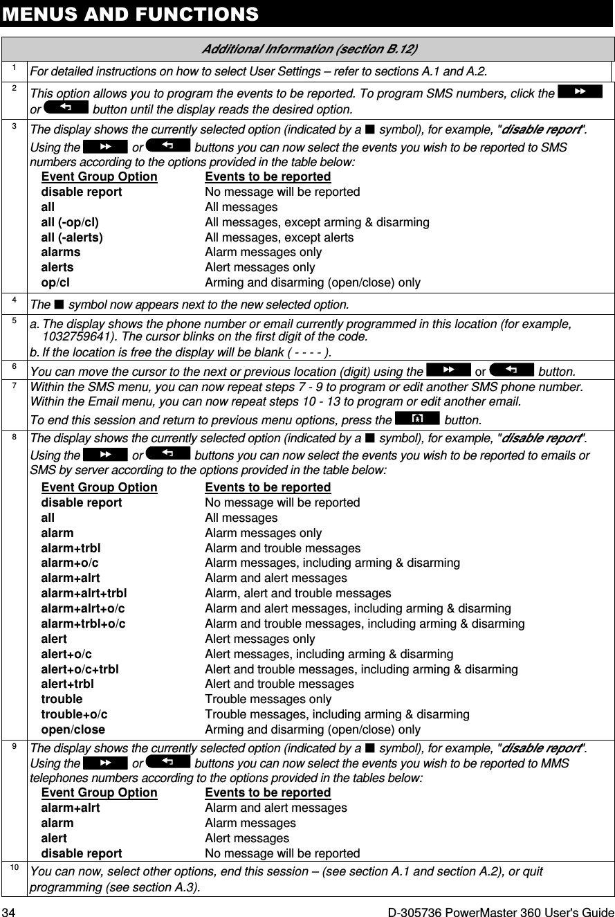
![MENUS AND FUNCTIONS 30 D-305736 PowerMaster 360 User's Guide Additional Information (section B.10 - B.11) 1 For detailed instructions on how to select User Settings – refer to sections A.1 and A.2. 2 The display shows the current setting (indicated by a symbol), for example, [enable autoarm]. You can now select either to enable or disable auto-arming using the or button. 3 The symbol now appears next to the newly selected option. 4 The display shows the current setting of the Auto-Arm Time, for example, "12:00 PM", with the cursor blinking on the first hour digit "1". For detailed explanation of how to set the time - refer to Section B.8 B. 5 The saved auto arm time is displayed without the cursor, for example, "08:30 A". 6 You can now select another option in the User Settings menu (see section A.1 and section A.2), or quit programming (see section A.3). B.12 Programming Email, MMS and SMS Reporting The PowerMaster 360 system can be programmed to send various event notification messages such as alarm, arming or trouble events, to 4 SMS telephone numbers (if a GSM option is installed). In addition, for users who are connected to the PowerManage server, event notification messages can be sent to 4 private emails as well as to 4 private MMS and SMS telephone numbers via the server. These reports can be programmed either instead of or in addition to the reports transmitted to the monitoring company. Further details about the event notification by SMS are provided in Chapter 5. Event Reporting and Control by SMS. Here you can program: ♦ The specific events you wish the system to report. ♦ The 1st, 2nd, 3rd, and 4th MMS, SMS numbers and emails for reporting alarm and other event messages to private subscribers. Carefully read the section titled "Additional Information" according to the indicated references1 etc – see table at end of this section. SMS REPORT A. To Program Events to be Reported by SMS 1. PRIVATE REPORT Enter the [USER SETTINGS] menu, select the [PRIVATE REPORT] option and press . 1 2. SMS REPORT The display will read [SMS REPORT]. To enter this option, press . 3. REPORTED EVENTS When the display reads [REPORTED EVENTS] press . 2 disable report The display shows the currently selected option. 4. or Click the or button until the display reads the event group you wish to be reported via SMS, for example, [alarms]. 3 alarms 5. When you are satisfied with the setting, press to confirm. alarms A "Happy Tune" ☺ sounds. The display confirms the set events to be reported, and returns to step 3. 4, 10 ☺ Return to step 3](https://usermanual.wiki/Visonic/PMASTER360/User-Guide-2912169-Page-30.png)
![MENUS AND FUNCTIONS D-305736 PowerMaster 360 User's Guide 31 B. To Program SMS Telephone Numbers 6. REPORTED EVENTS Click the or button until the display reads the SMS phone number you wish to program or edit (out of 4 SMS numbers), for example, "2nd SMS tel#", and press . or 7. 2nd SMS tel# 8. 080168593 To program or edit the phone number, at the blinking cursor position enter the SMS phone number, for example, “5080168593”, using the numerical keypad. 5, 6 9. When done, press to confirm. 8032759333 A "Happy Tune" ☺ sounds, the display confirms the SMS phone number and returns to step 7. 7, 10 ☺ Return to step 7 EMAIL BY SERVER A. To Program Events to be Reported by Email via the server 1. PRIVATE REPORT Enter the [USER SETTINGS] menu, select the [PRIVATE REPORT] option and press . 1 2. SMS REPORT When the display reads [SMS REPORT] press . 3. EMAIL BY SERVER To enter this option, press . The display reads [1st E-MAIL]. 4. 1st E-MAIL Click the or button until the display reads the email you wish to program (out of 4 emails), for example, [2nd E-MAIL] and then press . or 2nd E-MAIL Address The display reads [Address]. 5. Click the button. The display reads [E-MAIL Events]. 6. E-MAIL Events Press the button. disable report The display shows the currently selected option. 7. or Click the or button until the display reads the event group you wish to be reported via email, for example, [alarm]. 8 alarm 8. When you are satisfied with the setting, press to confirm. alarm A "Happy Tune" ☺ sounds. The display confirms the set events to be reported, and returns to step 6. 4, 10 ☺ Return to step 6 B. To Program Emails 9. Continue from step 4 in the previous section. 10. 1st E-MAIL Click the or button until the display reads the email you wish to program or edit, for example, "2nd E-Mail", and press . or 2nd E-MAIL](https://usermanual.wiki/Visonic/PMASTER360/User-Guide-2912169-Page-31.png)
![MENUS AND FUNCTIONS 32 D-305736 PowerMaster 360 User's Guide 11. Address When the display reads [Address], press . 12. info@visonic.com To program or edit the email, at the blinking cursor position enter the email, for example, “info@visonic.com”, using the alphanumerical keypad. 5, 6 13. When done, press to confirm. info@visonic.com A "Happy Tune" ☺ sounds, the display confirms the email and returns to step 11. 7, 10 ☺ Return to step 11 SMS/MMS BY SERVER A. To Program Events to be Reported by SMS via the server 1. PRIVATE REPORT Enter the [USER SETTINGS] menu, select the [PRIVATE REPORT] option and press . 1 2. SMS REPORT When the display reads [SMS REPORT] press repeatedly until the display reads [SMS/MMS BY SRVR]. 3. SMS/MMS BY SRVR To enter this option, press . The display reads [1st SMS/MMS]. 4. 1st SMS/MMS Click the or button until the display reads the SMS phone number you wish to program (out of 4 SMS numbers), for example, [2nd SMS/MMS], and press .. or 2nd SMS/MMS Telephone num. The display reads [Telephone num.]. 5. Click the button. The display reads [SMS Events]. 6. SMS Events Press the button. disable report The display shows the currently selected option. 7. or Click the or button until the display reads the event group you wish to be reported via SMS, for example, [alarm]. 8 alarm 8. When you are satisfied with the setting, press to confirm. alarm A "Happy Tune" ☺ sounds. The display confirms the set events to be reported, and returns to step 6. 4, 10 ☺ Return to step 6 B. To Program Events to be Reported by MMS via the server 9. PRIVATE REPORT Enter the [USER SETTINGS] menu, select the [PRIVATE REPORT] option and press . 1 10. SMS REPORT When the display reads [SMS REPORT] press repeatedly until the display reads [SMS/MMS BY SRVR]. 11. SMS/MMS BY SRVR To enter this option, press . The display reads [1st SMS/MMS].](https://usermanual.wiki/Visonic/PMASTER360/User-Guide-2912169-Page-32.png)
![MENUS AND FUNCTIONS D-305736 PowerMaster 360 User's Guide 33 12. 1st SMS/MMS Click the or button until the display reads the MMS phone number you wish to program (out of 4 MMS numbers), for example, [2nd SMS/MMS], and press . or 2nd SMS/MMS Telephone num. The display reads [Telephone num.]. 13. Click the button repeatedly until the display reads [MMS Events]. 14. MMS Events Press the button. disable report The display shows the currently selected option. 15. or Click the or button until the display reads the event group you wish to be reported via MMS, for example, [alarm]. 9 alarm 16. When you are satisfied with the setting, press to confirm. alarm A "Happy Tune" ☺ sounds. The display confirms the set events to be reported, and returns to step 14. 4, 10 ☺ Return to step 14 C. To Program MMS and SMS Telephone Numbers 17. Continue from step 4 in section A. “To Program Events to be Reported by SMS via the server” 18. 1st SMS/MMS Click the or button until the display reads the SMS/MMS telephone number you wish to program or edit (out of 4 SMS/MMS numbers), for example, "2nd SMS/MMS", and press . or 2nd SMS/MMS 19. Telephone num. When the display reads [Telephone num.], press 20. 895283584 To program or edit the MMS/SMS number, at the blinking cursor position enter the MMS/SMS telephone number, for example, “895283584”, using the alphanumerical keypad. 5, 6 21. When done, press to confirm. 895283584 A "Happy Tune" ☺ sounds, the display confirms the MMS/SMS telephone number and returns to step 19. 10 ☺ Return to step 19](https://usermanual.wiki/Visonic/PMASTER360/User-Guide-2912169-Page-33.png)
![MENUS AND FUNCTIONS D-305736 PowerMaster 360 User's Guide 35 B.13 Enabling / Disabling the Squawk Option The PowerMaster 360 system (and its wireless sirens) can be set to produce a short "Squawk" of audible feedback to assist you when you use your keyfob to arm (1 beep) and disarm (2 beeps) the PowerMaster 360 system (operates in a similar manner to a car alarm). ♦ Here you can enable / disable the Squawk. Carefully read the section titled "Additional Information" according to the indicated references1 etc – see table at end of this section. 1. SQUAWK Enter the [USER SETTINGS] menu, select the [SQUAWK] option and press . 1 Squawk ON The display shows the currently selected setting. 2 2. or Click the or button until the display reads the desired setting, for example, "Squawk OFF" and press the button to confirm. Squawk OFF 3. Squawk OFF A "Happy Tune" ☺ sounds. The display confirms the saved setting, and then returns to the User Settings menu, step 1. 3, 4 ☺ Return to step 1 Additional Information (section B.13) 1 For detailed instructions on how to select User Settings – refer to sections A.1 and A.2. 2 a. The display shows the currently selected setting (indicated by a symbol), for example, [Squawk ON]. b. You can now enable (ON) or disable (OFF) the Squawk option using the or button. 3 The symbol now appears next to the new selected option. 4 You can now select another option in the User Settings menu (see section A.1 and section A.2), or quit programming (see section A.3). B.14 Serial Number The SERIAL NUMBER menu enables reading the system serial number and similar data for support purposes only. ♦ Here you can read the system serial number and other relevant data. Carefully read the section titled "Additional Information" according to the indicated references1 etc – see table at end of this section. 1. SERIAL NUMBER Enter the [USER SETTINGS] menu, select the [SERIAL NUMBER] option and press . 1 2. 090703000 Displays the control panel serial number. 3. JS702766 L18.154 Displays the control panel software version. 4. Panel ID: 100005 Displays the control panel ID for PowerManage connectivity. 5. J-702770 L18.154 Displays the control panel default version. 6. JS702767 L01.023 Displays the control panel boot version.](https://usermanual.wiki/Visonic/PMASTER360/User-Guide-2912169-Page-35.png)
![MENUS AND FUNCTIONS 36 D-305736 PowerMaster 360 User's Guide 7. JS702768 L02.003 Displays the control panel Remote Software Upgrade downloader version. 8. PL8.0.10 1111 Displays the PowerLink software version. ☺ Return to step 2 2, 3 Additional Information (section B.14) 1 For detailed instructions on how to select the Setting Options – refer to sections A.1 and A.2. 2 To end this session and return to previous menu options, press the button. 3 You can now select another option in the User Settings menu (see section A.1 and section A.2), or quit programming (see section A.3). B.15 PowerLink Parameters* The PLNK curr.params menu enables reading the current IP address, subnet mask and default gateway of the PowerLink for support purposes only. ♦ Here you can read the current IP address of the PowerLink and other relevant data. Carefully read the section titled "Additional Information" according to the indicated references1 etc – see table at end of this section. 1. PLNK curr.params Enter the [USER SETTINGS] menu, select the [PLNK curr.params] option and press . 1 2. Curr.IP address Displays the current PowerLink IP address. xxx.xxx.xxx.xxx 3. Curr.subnet mask Displays the current PowerLink subnet mask. xxx.xxx.xxx.xxx 4. Current Gateway Displays the current PowerLink default gateway. xxx.xxx.xxx.xxx ☺ Return to step 2 2, 3 Additional Information (section B.15) 1 For detailed instructions on how to select the Setting Options – refer to sections A.1 and A.2. 2 To end this session and return to previous menu options, press the button. 3 You can now select another option in the User Settings menu (see section A.1 and section A.2), or quit programming (see section A.3). * If the Broadband Module is not registered to the PowerMaster, this menu will not be displayed.](https://usermanual.wiki/Visonic/PMASTER360/User-Guide-2912169-Page-36.png)
![TESTING THE SYSTEM 40 D-305736 PowerMaster 360 User's Guide 7. Testing the System Periodic Test The components of your security system are designed to be maintenance-free as much as possible. Nevertheless, it is mandatory to test the system at least once a week and after an alarm event to verify that all system sirens, detectors, keyfobs, keypads and other peripherals function properly. Proceed as described in this section and if there is any problem, notify your installer at once. The test is performed in four parts: Siren Test: Each siren of the system is automatically activated for 3 seconds (outdoor sirens with low volume). In addition, the system tests the siren of enrolled smoke sensors. Temperature Sensor Test: When Temperature Sensors are enrolled in the system, the Virtual Keypad displays the temperature of each zone in Celsius or Fahrenheit. Other Device Test: Each of the other devices in the system is activated by the user and the display indicates which devices were not yet tested. The "it's me" indication helps to identify the untested devices if necessary. A counter also indicates the number of devices that remain untested. Email Test: Generates an event to be sent to the predefined private email addresses (see Chapter 4, section B.12) Carefully read the section titled "Additional Information" according to the indicated references1 etc – see table at end of this section. A. To Enter the Periodic Test Menu 1. READY 00:00 Make sure the system is disarmed and then press the button repeatedly until the display reads "PERIODIC TEST" and press . 1 PERIODIC TEST 2. ENTER CODE: The screen will now prompt you to enter your user code. 3. CODE Enter your User Code. 2 3 ☺ Go to step 4 B. To Test the Sirens 4. SIRENS TEST The display now reads [SIRENS TEST]. 5. To initiate the siren test press . Immediately after pressing , all 5 LEDs on the panel should light (LED test). 4 SIREN N The display now reads [SIREN N], where "N" indicates the zone location assigned to the siren that is currently being tested. The first siren enrolled in the panel sounds for 3 seconds after which the PowerMaster 360 system will automatically repeat the procedure for the next siren enrolled in the system until all sirens are tested. 5 You should listen to the sirens sounds and make sure that all sirens sound. Once all the sirens have been tested, the control panel will now test the sirens of smoke sensors that are enrolled in the alarm system. The display now reads [Zxx: SMOKE SIREN], where "Zxx" indicates the zone number of the smoke sensor, and alternates with [<OK> TO CONTINUE]. During this time, the siren of the tested smoke sensor will sound for up to one minute. Press to test the siren of the next smoke sensor. 6. SIRENS TESTS END When all the sirens test is complete, the display reads [SIREN TESTS END]. Press the or the button to confirm the test and then move to the next step for zone temperature display. or C. To Display the Temperature 7. TEMPERATURE TEST The display now reads [TEMPERATURE TEST]. 8. To display the temperature of zones on the control panel, press . 6](https://usermanual.wiki/Visonic/PMASTER360/User-Guide-2912169-Page-40.png)
![TESTING THE SYSTEM D-305736 PowerMaster 360 User's Guide 41 Z01 24.5°°°°C The Virtual Keypad reads the temperature of each zone. The display alternates between the temperature, the sensor number and the sensor location. 7 Repeatedly click the button to review the temperature of each zone (by Temperature Sensor). Z01:Temp. Sensor Guest room 9. DEVICE TESTS END When the temperature of all zones has been reviewed, the display reads [DEVICE TESTS END]. Press the or the button to confirm the test and then move to the next step to test the other devices. or D. To Test all other Devices TEST ALL DEVICES The display now reads [TEST ALL DEVICES]. 10. To enter the devices test procedure, press . 11. NOT ACTIVE NNN The display reads [NOT ACTIVE NNN]. NNN indicates the number of enrolled devices in the panel that have not been tested yet. This number automatically drops one count for every tested device. To initiate devices test, press . Z01 NOT ACTIVE NNN The display shows the 1st device in the list of untested devices. The display alternates between the device number, the device type (e.g. magnetic contact, keyfob, keypad, etc.), and the device location. The test is performed by activating each device as explained in point 8 in the Additional Information table below. Z01 CONTACT FRONT DOOR 12. Click to scroll through the list of all untested devices. 9 13. DEVICE TESTS END When all devices have been activated, the display reads [DEVICE TESTS END] followed by [READY 00:00]. READY 00:00 or Press the or the button to confirm the test and then move to the next step to test the email. E. To Test Emails 14. E-MAIL TEST The display now reads [E-MAIL TEST]. 10 15. To enter the email test procedure, press . Please wait… 16. Pls chck MailBox Check the private email inbox to view the sent email. ☺ Return to step 14 Additional Information (Periodic Test) 1 Display shown in disarm state when all zones are secured (00:00 or other digits show present time). 2 If you have not already changed your personal code number, use the default setting – 1111. 3 If the INSTALLER CODE is used to enter the Periodic Test instead of the USER CODE, the devices LED will also provide the link quality indication – see PowerMaster 360 Installer's Guide. 4 To skip the SIRENS TEST and select the other devices TEST, press . 5 The Periodic test can be performed on a maximum of two wireless sirens and the sirens of enrolled smoke sensors. Outdoor sirens are activated with low volume. 6 If no temperature sensor is enrolled in the system, the display reads "NO EXISTING DEV.".](https://usermanual.wiki/Visonic/PMASTER360/User-Guide-2912169-Page-41.png)
![TESTING THE SYSTEM 42 D-305736 PowerMaster 360 User's Guide 7 The displayed temperature can be in Celsius or Fahrenheit according to the programmed settings of the Temperature Sensor. 8 To activate system devices during the "Periodic Test"; make sure the device LED lights when activated: Contact sensor: Open or close the door or window protected by the contact. Motion sensors: Perform a "walk test" of the detector as explained in the detector's datasheet. Smoke sensors: Perform a "Diagnostic test" as explained in the detector's datasheet. Keyfob: Activate any of the keyfob buttons. Keypads: Perform a disarm or arm routine or press any other key that activates the LED. Repeater: Follow the "Diagnostic Tests" described in the repeater's datasheet. Other devices: In general, follow the "Diagnostic Tests" described in the device's datasheet or activate any of its functions. 9 a. Three seconds after the device is displayed, the device LED blinks to assist you to identify ("it's me"). b. To end the session, press the button until the display reads [<OK> TO EXIT] and then press . 10 Testing emails must first be configured (see Chapter 4, B.12 “EMAIL BY SERVER”). Periodic Test per Partition In addition to the regular Periodic Test, you can also test zones for enrolled sensors (excluding temperature sensors and sirens) that are assigned to a selected partition. A. To Conduct the Periodic Test per Partition 1 1. P1:R P2:N P3:- Make sure the selected partition is disarmed and the other partitions are not in exit or entry delay and then press the partition ( ) button. MEMORY TROUBLE 2. SELECT PARTITION When the display reads [SELECT PARTITION], press the partition number of the zones you wish to test, for example, (Partition 1). 3. Partition 1 4. Press the button repeatedly until the display reads [PERIODIC TEST] and press . PERIODIC TEST 5. ENTER CODE: The screen will now prompt you to enter your Master user code. 6. CODE Enter your Master user code. 2 P1 SENSORS TEST 3 7. To enter the devices test procedure per partition, press . 8. NOT ACTIVE NNN The display reads [NOT ACTIVE NNN]. NNN indicates the number of enrolled devices in the panel that have not been tested yet. This number automatically drops one count for every tested device. Test per partition is performed by activating each device as explained in point 4 in the Additional Information table below. After a device has been activated, the control panel reads [Zxx IS ACTIVATED] and the "N" indicator drops one count. After all devices have been tested, the control panel reads [DEVICE TESTS END]. ↓↓↓↓ DEVICE TESTS END 9. Press . 5 ☺ Return to step 3](https://usermanual.wiki/Visonic/PMASTER360/User-Guide-2912169-Page-42.png)
![TESTING THE SYSTEM D-305736 PowerMaster 360 User's Guide 43 Additional Information (Periodic Test per Partition) 1 Partitioning must be enabled by your installer. 2 If you have not already changed your personal code number, use the default setting – 1111. 3 To abort, press the button; the display reads [<OK> TO END]. Press the button. 4 To activate system devices during the "Periodic Test Per Partition"; make sure the device LED lights when activated: Contact sensor: Open or close the door or window protected by the contact. Motion sensors: Perform a "walk test" of the detector as explained in the detector's datasheet. Smoke sensors: Perform a "Diagnostic test" as explained in the detector's datasheet. 5 Periodic test per partition will be interrupted (the panel returns to selected partition display) upon occurrence of one of the following: 1) Disarm event by keyfob, keypad or pendant assigned to a selected partition; 2) PANIC, FIRE or EMERGENCY event.](https://usermanual.wiki/Visonic/PMASTER360/User-Guide-2912169-Page-43.png)
![MAINTENANCE D-305736 PowerMaster 360 User's Guide 45 READY 00:00 1. ENTER CODE:_ 2. CODE When the Virtual Keypad display reads [ENTER CODE: _], enter the current master user code. LIST OF EVENTS The "Happy Tune" will sound and the Virtual Keypad display will read [LIST OF EVENTS]. (see Important Note!) 3. Click the button. The latest event will be shown. Z13 alarm The event is displayed in two parts, for example, "Z13 alarm" then "09/02/10 3:37 P". The two displays will be shown alternately until clicking again to move to the next event or until the event log times out (4 minutes). 09/02/10 3:37 P 4. Click the button as many times as necessary to read all the required data. Important Note! Entering an incorrect code 5 times in a row will initiate a 30-second penalty lockout of the keypad. Attention: The system will not allow you to erase the event log. Only the installer is authorized to view and perform this function. Exiting the Event Log 1. or Click the or button from anywhere within the event log. The Virtual Keypad display will read [<OK> TO EXIT]. <OK> TO EXIT 2. Click the button. READY 00:00 The system reverts to the normal operating mode.](https://usermanual.wiki/Visonic/PMASTER360/User-Guide-2912169-Page-45.png)
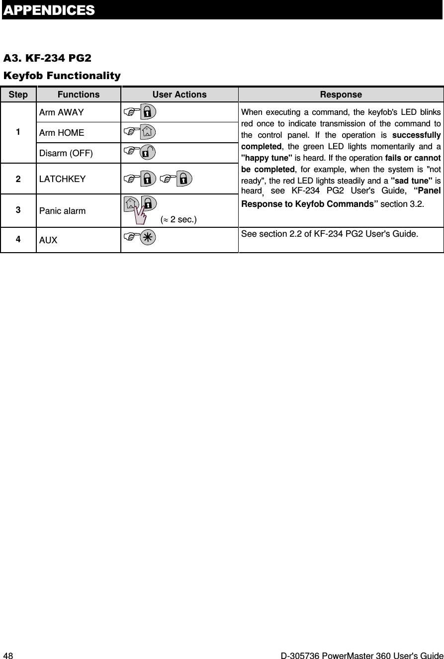
![APPENDICES 46 D-305736 PowerMaster 360 User's Guide APPENDIX A. FUNCTIONS OF CONTROLLING DEVICES A1. KP-160 PG2 Arming and Disarming the System Step Operation User Actions Keyboard & Panel Response Optional 1 Select a PARTITION (if Partition is enabled) Any combination of The selected key blinks. 2 Arm AWAY + [ ] The selected key and the "Present Prox Tag" icon ( ) begin to blink and prompt you to present your Tag. The keypad's LED blinks red once to indicate transmission of the arming command to the control panel. The LED and the buzzer then indicate the control panel's response – see KP-160 PG2 User's Guide, “System Status and Indications” section 3.3. Arm HOME + [ ] Disarm (OFF) + [ ] Optional 3 Quick arm AWAY (If Quick Arm is enabled) (≈ 2 sec.) Quick arm HOME (If Quick Arm is enabled) (≈ 2 sec.) Optional 4 INSTANT (After arming HOME/ AWAY) LATCHKEY (After arming AWAY) Initiating Alarms Alarms Actions Response Notes Emergency alarm (≈ 2 sec.) See section 3.3. in KP-160 PG2 User's Guide When pressing the Fire or Emergency icons, the KP-160 PG2 starts beeping. After pressing the button for approx. 2 seconds, the KP-160 PG2 sends the command. Fire alarm (≈ 2 sec.) Panic alarm (≈ 2 sec.) When pressing the Fire and Emergency icons together, the KP-160 PG2 starts beeping. After pressing the button for approx. 2 seconds, the KP-160 PG2 sends the Panic command. Zone Status Alarms Response Notes For NOT READY ( ) / BYPASSED ( ) Upon each press of the key, the next zone number appears on the zone # display, . Zone Status when working with Partitions Alarms Response Notes For NOT READY ( ) / BYPASSED ( ) / / Upon each press of the key, the next zone number assigned to the pressed Partition number appears on the zone # display, .](https://usermanual.wiki/Visonic/PMASTER360/User-Guide-2912169-Page-46.png)
![APPENDICES D-305736 PowerMaster 360 User's Guide 47 A2. KP-140/141 PG2 Arming and Disarming the System Step Basic Arming User Actions Keypad & Panel Response 1 Select a PARTITION (Partition enabled) or or The selected button lights. 2 Arm AWAY The selected button starts blinking and prompts you to enter your "User Code" or present your Tag. See step 3. Arm HOME Disarm (OFF) Quick arm AWAY (≈ 2 sec.) The keypad's LED blinks red once to indicate transmission of the arming command to the control panel. The control panel's response is then indicated on the keypad via the LED and the buzzer – see KP-140 PG2 User's Guide, “Panel Response to Keypad Commands” section 3.5 Quick arm HOME (≈ 2 sec.) 3 Enter USER CODE or present Proximity TAG. [USER CODE] or [present TAG] [DURESS CODE] (2580 by default) 4 INSTANT (After arming HOME/ AWAY) The keypad's LED blinks red once to indicate transmission of the command to the control panel. The control panel's response is then indicated on the keypad via the LED and the buzzer – see KP-140 PG2 User's Guide, “Panel Response to Keypad Commands” section 3.5. LATCHKEY (After arming AWAY) Initiating Alarms Other Functions Alarm Actions Response Function User Actions Response Emergency alarm (≈ 2 sec.) See KP-140 PG2 User's Guide, “Panel Response to Keypad Commands” section 3.5 AUX Function (see Note) See section 3.5 of KP-140 PG2 User's Guide. Fire alarm (≈ 2 sec.) STATUS indication See section 3.6 of KP-140 PG2 User's Guide. Panic alarm (≈ 2 sec.) Note: For the AUX button configuration, see the KP-140 PG2 Installation Instructions.](https://usermanual.wiki/Visonic/PMASTER360/User-Guide-2912169-Page-47.png)