Visonic PWRMCOMPLETE Wireless alarm control system User Manual
Visonic Inc. Wireless alarm control system
UserManual.wiki
>
Visonic
>
PWRMCOMPLETE User Manual
>
User Manual
Contents
1.
User Manual
2.
User manual
User Manual
Navigation menu
Upload a User Manual
Namespaces
Wiki Guide
HTML
PDF
Info
Views
User Manual
Discussion / Help
Navigation
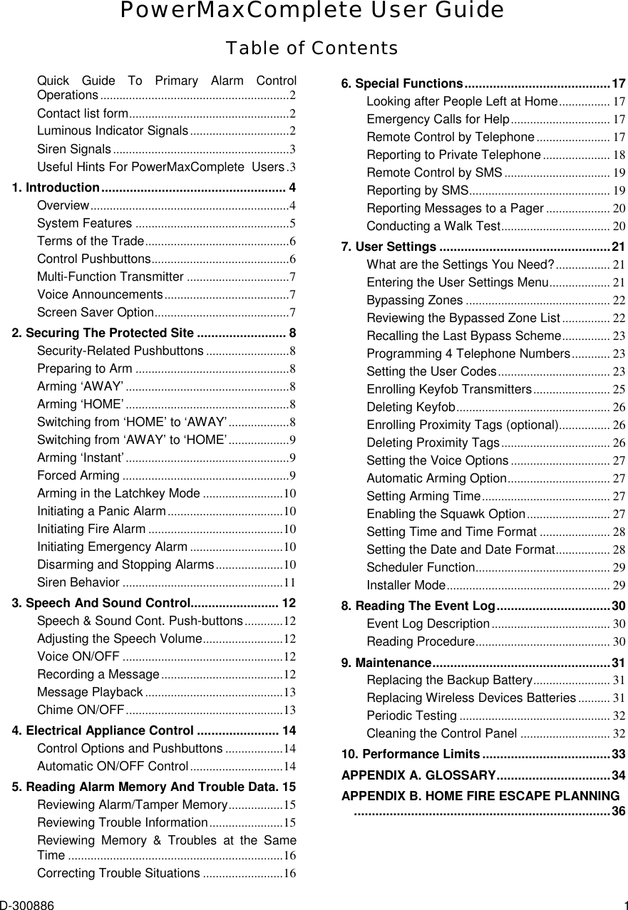
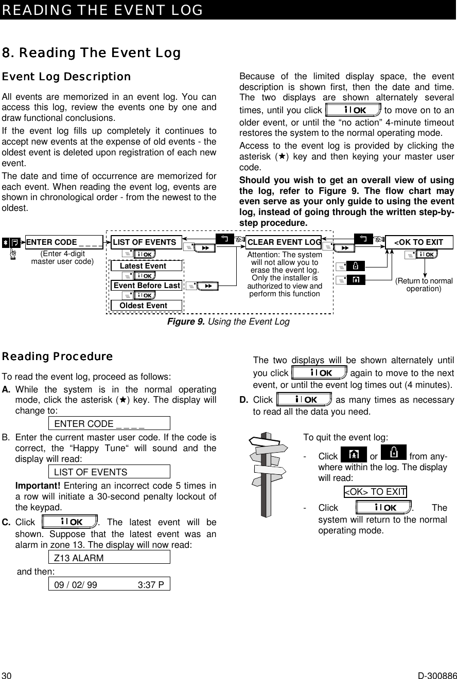
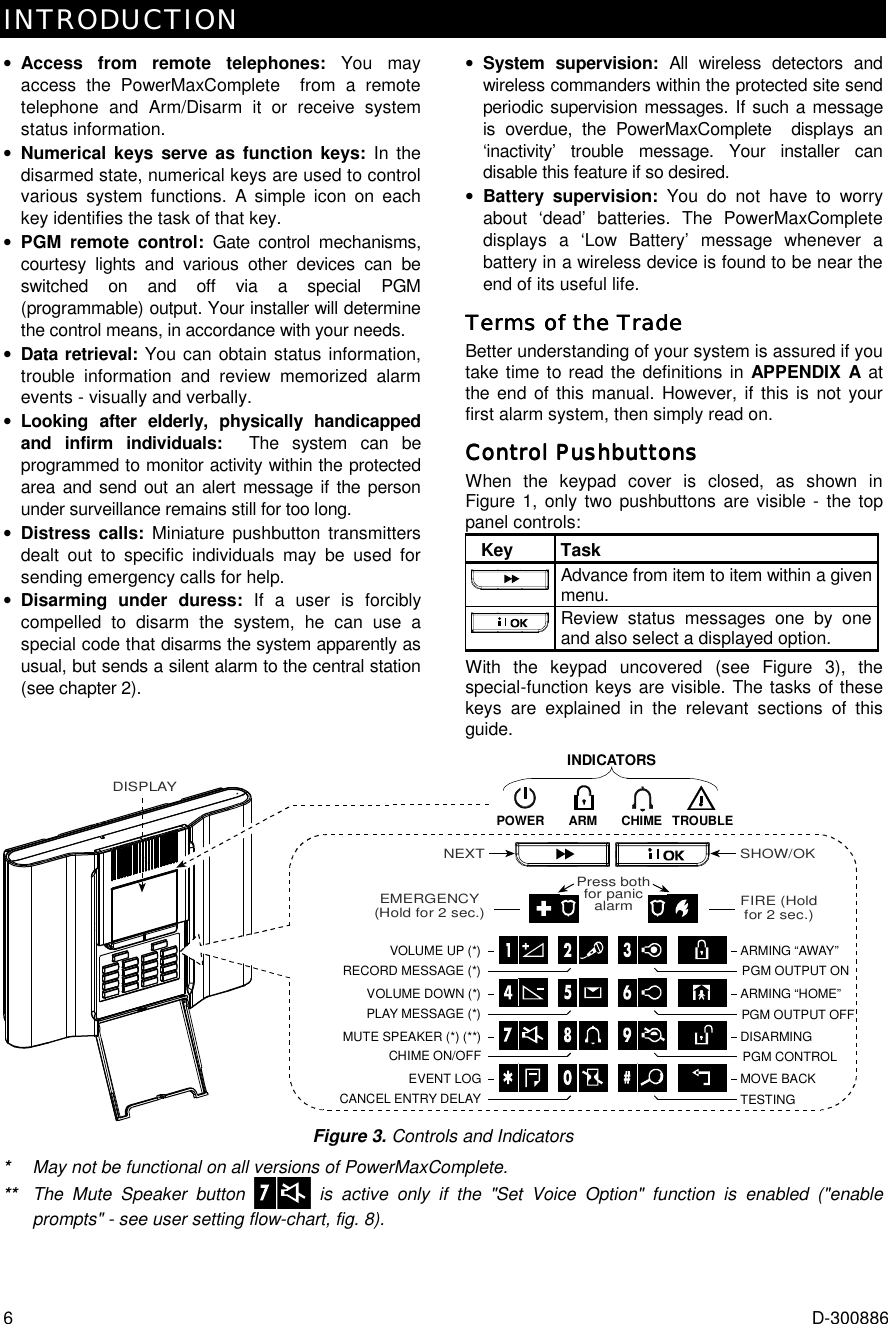
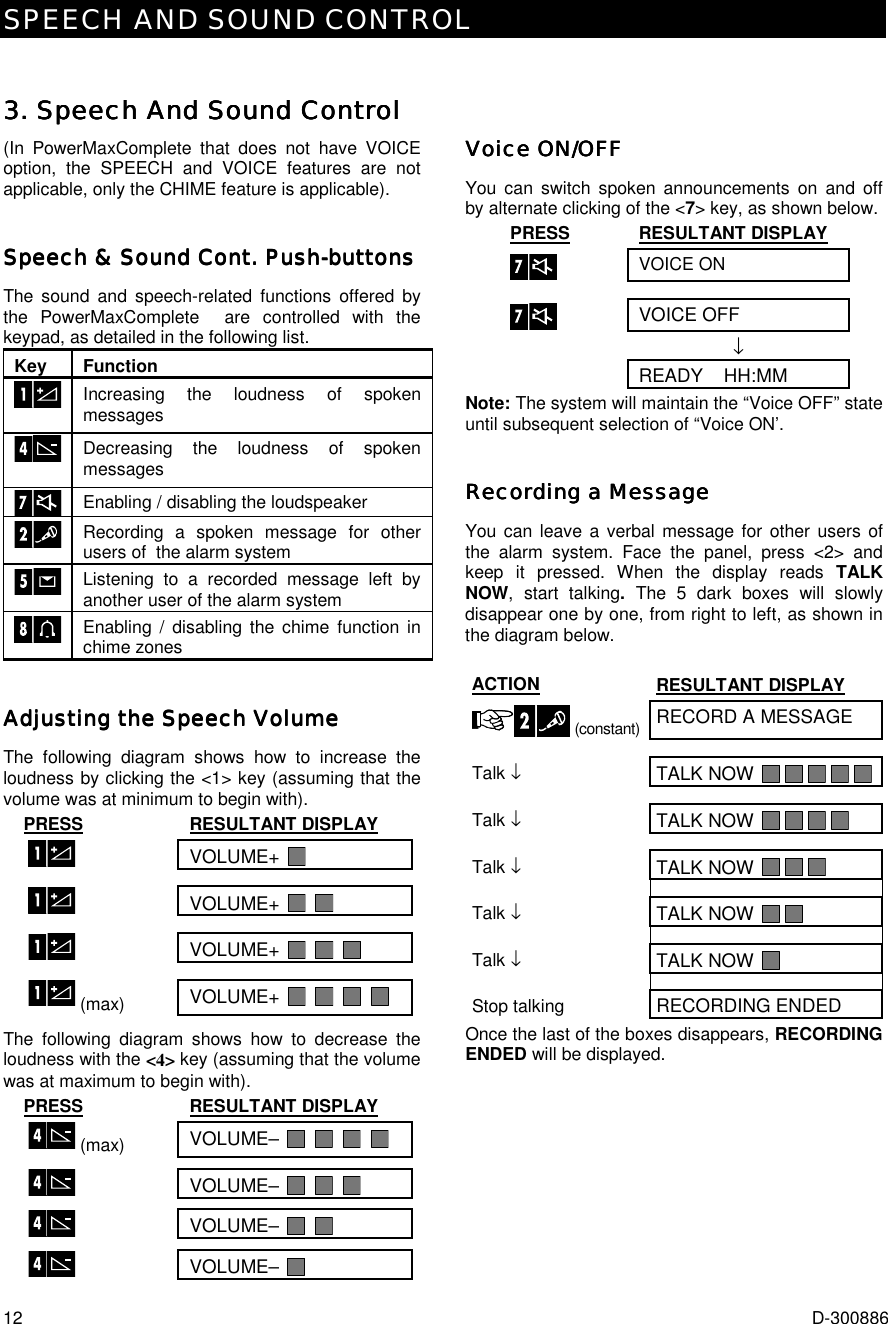
![2 D-300886 Quick Guide To Primary Alarm Control OperationsQuick Guide To Primary Alarm Control OperationsQuick Guide To Primary Alarm Control OperationsQuick Guide To Primary Alarm Control Operations QUICK REFERENCE TO PRIMARY ALARM CONTROL OPERATIONS Arming AWAY ........................................+ + [Code]* Arming AWAY-INSTANT ........................+ + [Code]* + + Arming HOME ........................................+ + [Code]* Arming HOME-INSTANT .......................+ + [Code]* + + Arming AWAY-LATCHKEY ...................+ + [Code]* + + Force Arming AWAY (system not ready) + + [Code]* + + (to silence the protest buzz) Force Arming HOME (system not ready)+ + [Code]* + + (to silence the protest buzz) Disarming and stopping alarms............+ + [Code] * The factory default master user code is 1 1 1 1. The code is not required if quick arming has been permitted by the installer. Change the factory default code to a secret code without delay (see section 7) Contact list formContact list formContact list formContact list form Dear Customer, Thank you for choosing PowerMaxComplete, a highly advanced wireless alarm control system produced by Visonic Ltd. Please note below the installer's telephone number to facilitate obtaining assistance. Company Name: ____________________________ Telephone Number: __________________________ Person to Contact: ___________________________ Also please make sure that you have the name and telephone number of the central station your system will report to. If you ever call the central station to ask questions, you should be able to come up with your "ACCOUNT NUMBER" used to identify your alarm system to the central station. Obtain this information from your installer and write it. Monitoring Station’s Name _____________________ Telephone Number: __________________________ My Account Number: _________________________ If your system was set by the installer to contact private telephone numbers, note down the 4 telephone numbers that your installer programmed to be called: Phone No. 1: _______________________________ Phone No. 2: _______________________________ Phone No. 3: _______________________________ Phone No. 4: _______________________________ Luminous Indicator SignalsLuminous Indicator SignalsLuminous Indicator SignalsLuminous Indicator Signals Indicator Behavior Significance (red) Lights steadily Flashes No light The system is in the armed state (AWAY MODE) The system is in the armed state (HOME MODE) The system is presently in the disarmed state (orange) Lights steadily No light A state of trouble is presently being detected No trouble - all is well (green) Lights steadily No light The chime function is active - chime zones will chime when disturbed. The chime function is inactive - chime zones will not chime when disturbed. (green) Lights steadily No light AC power is supplied to the control panel The system is operating on backup battery power](https://usermanual.wiki/Visonic/PWRMCOMPLETE.User-Manual/User-Guide-973248-Page-2.png)
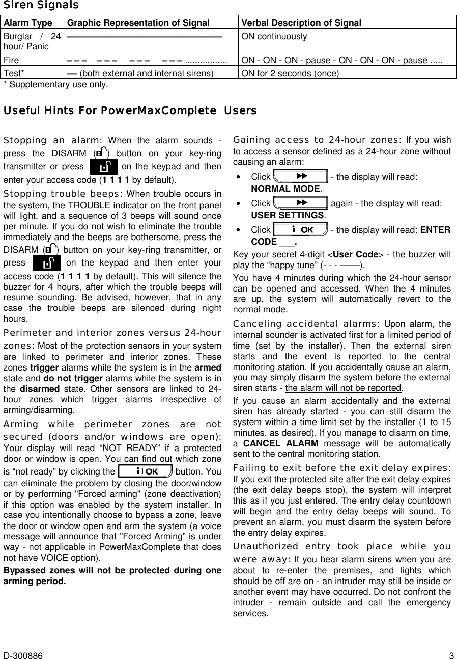
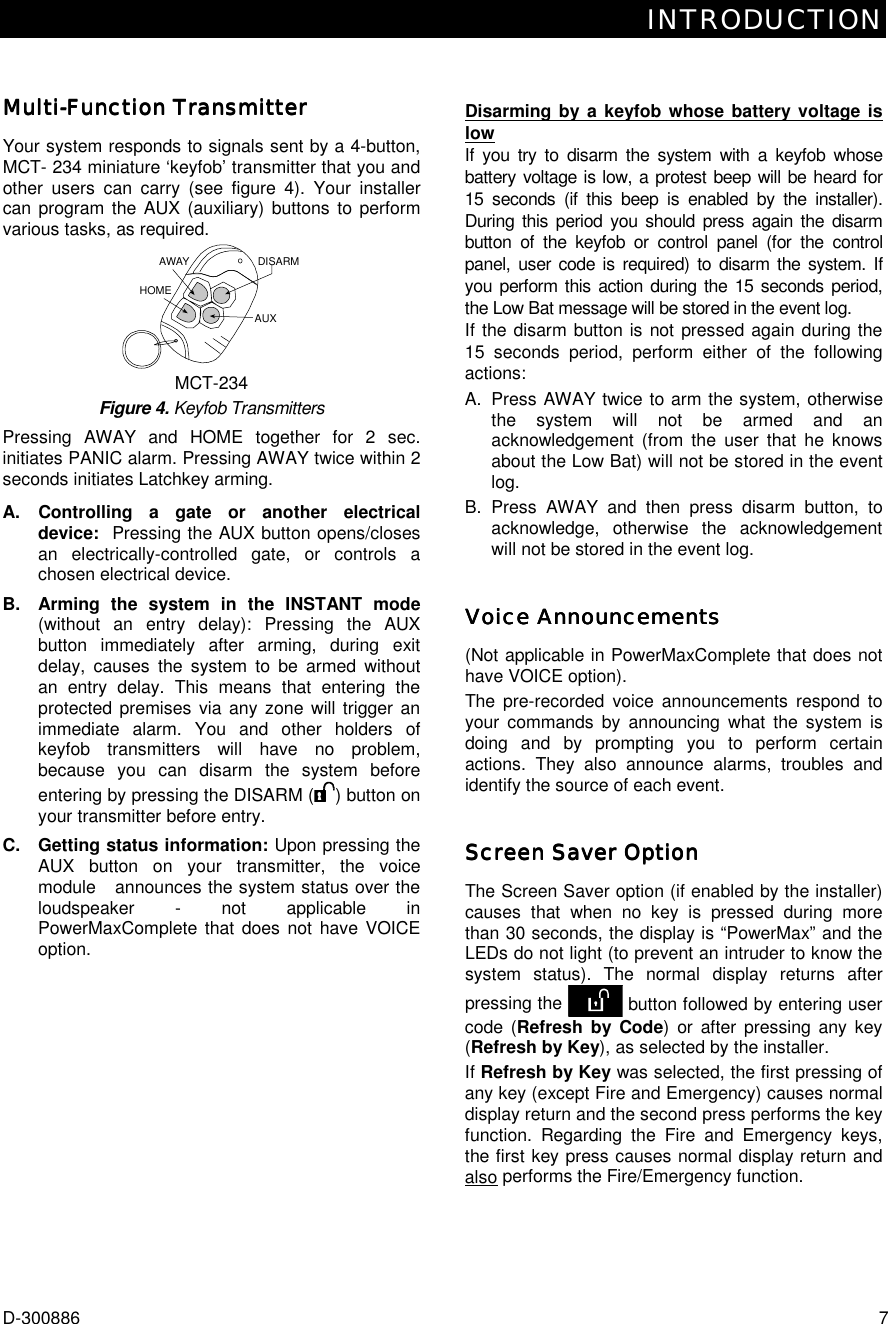
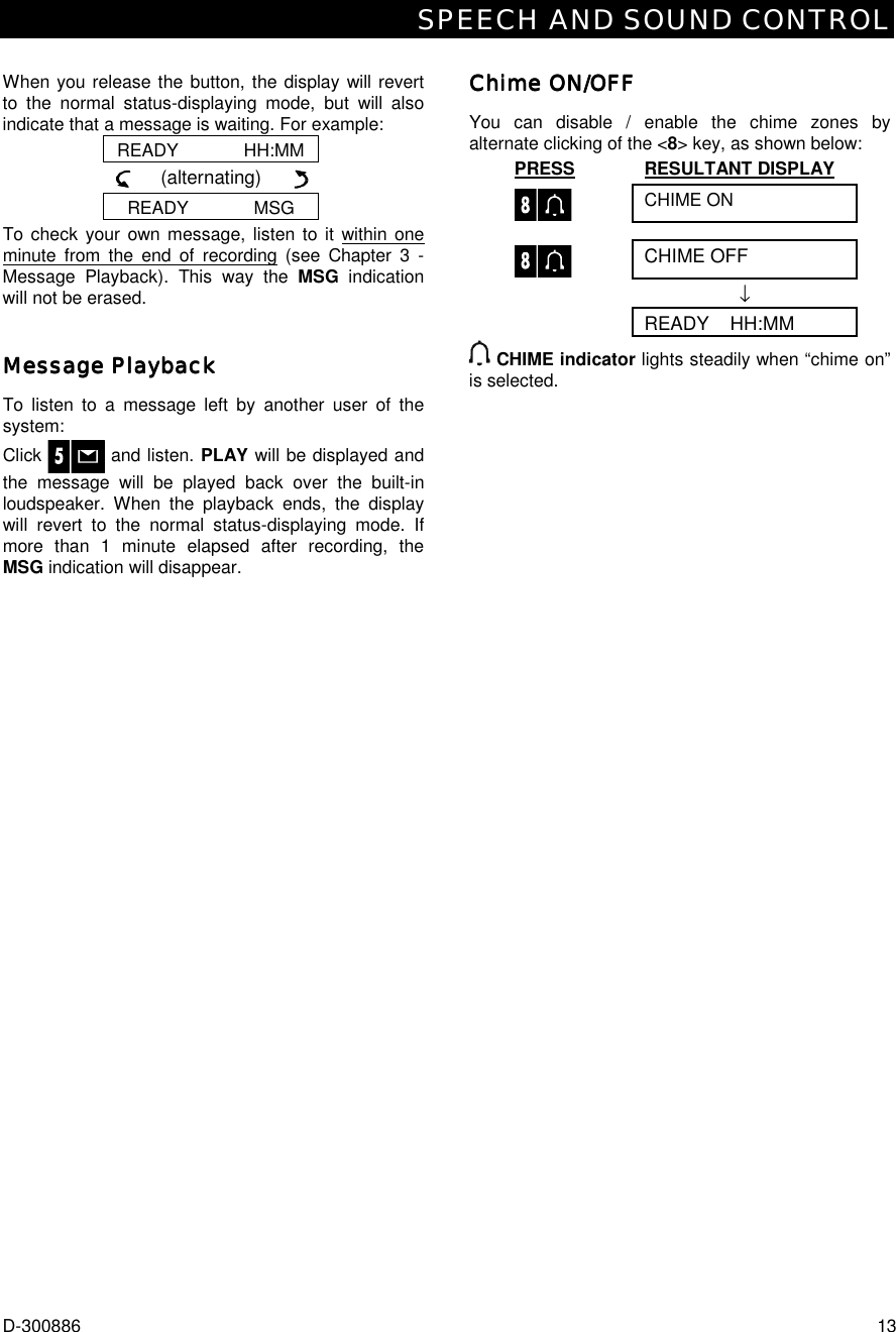
![SECURING THE PROTECTED SITE D-300886 9 Switching from ‘AWASwitching from ‘AWASwitching from ‘AWASwitching from ‘AWAY’ to ‘HOME’Y’ to ‘HOME’Y’ to ‘HOME’Y’ to ‘HOME’ Do not disarm the system - just press . Since this operation reduces the security level, the PowerMaxComplete will ask you to key in your master user code or user code, thus making sure that you are an authorized user. PRESS RESULTANT DISPLAY ENTER CODE _ _ _ ARMING HOME ↓ (Exit delay) ↓ [Enter code] Move to interior zone ARM HOME HH:HH ARM indicator flashes during the armed state. If an alarm occurred while the system was armed in the AWAY mode, the display will respond differently: PRESS RESULTANT DISPLAY ENTER CODE _ _ _ [Enter code] ARMING HOME ↓ (Exit delay) ↓ Move to interior zone HOME HH:HH (alternating) ARM HOME MEMORY ARM indicator flashes during the armed state. Arming ‘InsArming ‘InsArming ‘InsArming ‘Instant’tant’tant’tant’ You may arm AWAY or HOME without an entry delay - any detection in any zone will trigger an immediate alarm. If you wish to arm AWAY-INSTANT, proceed as follows. PRESS RESULTANT DISPLAY ARMING AWAY ARMING INSTANT (alternating) PLEASE EXIT NOW ↓ (Exit delay) ↓ Vacate the premises AWAY ARM indicator lights during the armed state. If you wish to arm HOME-INSTANT, proceed as follows: PRESS RESULTANT DISPLAY ARMING HOME ARMING INSTANT (alternating) ARMING HOME ↓ (Exit delay) ↓ ARM HOME HH:HH (alternating) Go to an internal zone ARM HOME INSTANT ARM indicator flashes during the armed state. Forced ArmingForced ArmingForced ArmingForced Arming Forced arming allows you to arm the system even though one zone or several zones are disturbed, and the NOT READY message is displayed. Automatic forced arming only works if the installer allowed this option while programming your system. Disturbed zones will be bypassed - they will not be armed. The protected site will not have maximum protection. Note: When forced arming is carried out, the buzzer “protests” by emitting a continuous tone during the exit delay until the last 10 seconds of the delay. You can silence this signal by pressing the arming button again. When NOT READY is displayed, Forced arming “AWAY” is performed as follows: PRESS RESULTANT DISPLAY ARMING AWAY ↓ PLEASE EXIT NOW ↓ (Exit delay) ↓ (to mute the buzzer) AWAY ARM indicator lights during the armed state. When NOT READY is displayed, Forced arming “HOME” is performed as follows: PRESS RESULTANT DISPLAY ARMING HOME ↓ (Exit delay) ↓ HOME HH:HH (To mute the buzzer)Go to interior zone ARM indicator flashes during the armed state.](https://usermanual.wiki/Visonic/PWRMCOMPLETE.User-Manual/User-Guide-973248-Page-9.png)
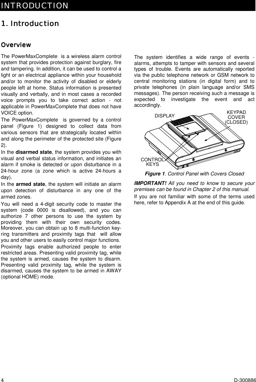
![SECURING THE PROTECTED SITE 10 D-300886 Arming in Arming in Arming in Arming in the Latchkey Modethe Latchkey Modethe Latchkey Modethe Latchkey Mode This mode is useful for a parent at work who wants to be sure that his children have returned from school and have disarmed the system. Arming in the “latchkey” mode means that a special “latchkey” message will be sent out when the system is disarmed by a “latchkey user”. Latchkey users are holders of user codes 5 through 8 or users of Keyfob transmitters 5 through 8. The latchkey message is considered an alert and not an alarm, and is therefore sent to the private telephones programmed by the user as targets for alert messages. Latchkey arming is possible only when you arm “AWAY”. To arm in the Latchkey mode, proceed as follows: PRESS RESULTANT DISPLAY ARMING AWAY ARMING LATCHKEY (Within 2 seconds) (alternating) PLEASE EXIT NOW Vacate the premises ↓ (Exit delay) ↓ AWAY ARM indicator lights during the armed state. Initiating a Panic AlarmInitiating a Panic AlarmInitiating a Panic AlarmInitiating a Panic Alarm You can generate a panic alarm manually in the disarmed and armed states alike. If this feature has been enabled by the installer (consult your installation company to determine if it has been enabled).The sequence will be as shown: PRESS RESULTANT DISPLAY PANIC ALARM Then, if or when the system is in the disarmed state: (Pressed simultaneously) READY HH:MM Note: If you are using a key-ring transmitter, press both AWAY and HOME buttons simultaneously for 2 seconds. To stop the alarm, press and then key in your valid user code. Initiating Fire AlarmInitiating Fire AlarmInitiating Fire AlarmInitiating Fire Alarm (This function is disabled in ACPO compliant version). You can generate a fire alarm manually (depends on the purchased PowerMaxComplete version - see PowerMaxComplete door label) in disarmed & armed states, as follows: PRESS RESULTANT DISPLAY FIRE Then, if or when the system is in the disarmed state: READY HH:MM To stop the alarm, press and then key in your valid user code. Initiating Emergency AlarmInitiating Emergency AlarmInitiating Emergency AlarmInitiating Emergency Alarm You can generate an emergency alarm manually (depends on the purchased system version - see PowerMaxComplete door label) in the disarmed and armed states as follows: PRESS RESULTANT DISPLAY EMERGENCY Then, if or when the system is in the disarmed state: READY HH:MM To stop the alarm, press and then key in your valid user code. Disarming and Stopping AlarmsDisarming and Stopping AlarmsDisarming and Stopping AlarmsDisarming and Stopping Alarms (This function is disabled in ACPO compliant version). Disarming the system stops the siren before it stops automatically, irrespective of whether the alarm was initiated in the armed or the disarmed state. After disarming, different displays may appear, depending on the current status of the system: A. Disarming - no events: After an uneventful armed term, the disarming operation will progress as shown: PRESS RESULTANT DISPLAY CODE _ _ _ [Enter code] READY HH:MM ARM indicator extinguishes B. Disarming after alarm, with all zones ready: If the zone that alarmed in the armed state is back to normal, the disarming operation will as shown: PRESS RESULTANT DISPLAY CODE _ _ _ code READY HH:MM (alternating) READY MEMORY ARM indicator extinguishes.](https://usermanual.wiki/Visonic/PWRMCOMPLETE.User-Manual/User-Guide-973248-Page-10.png)
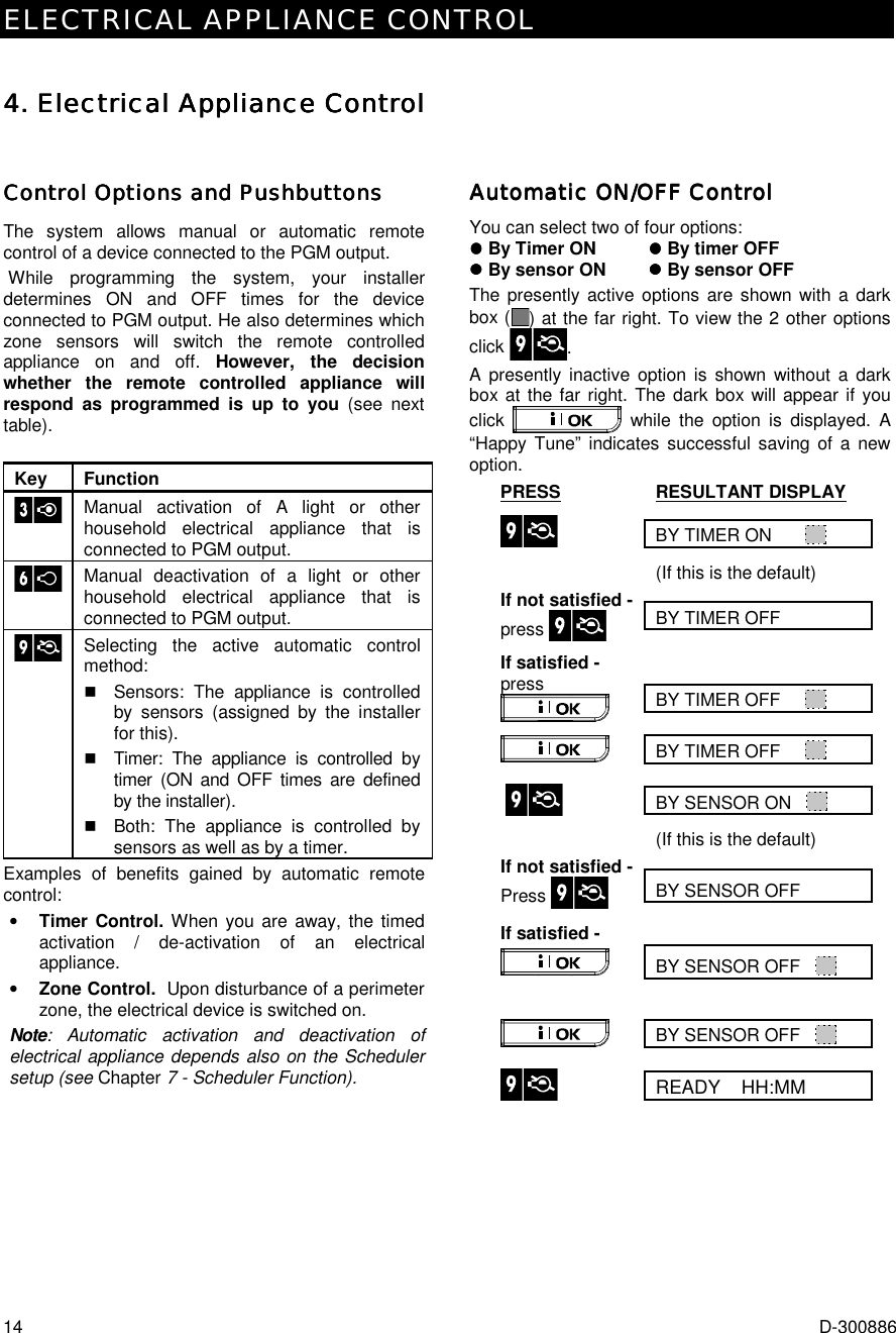
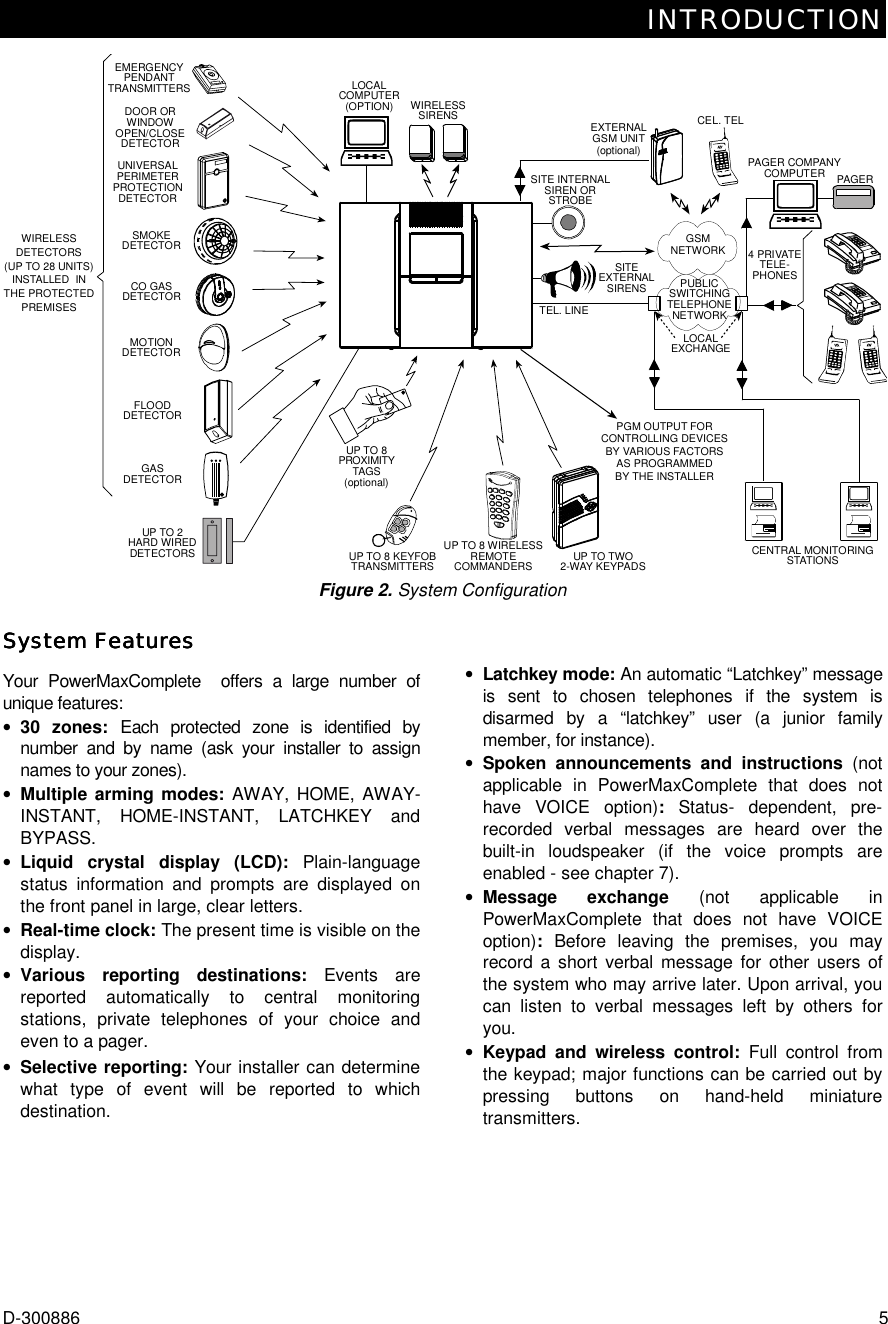
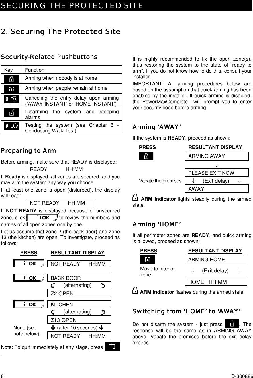
![SPECIAL FUNCTIONS D-300886 17 6. Special Functions6. Special Functions6. Special Functions6. Special Functions Looking after People Left at HomeLooking after People Left at HomeLooking after People Left at HomeLooking after People Left at Home An important characteristic of the PowerMaxComplete is its ability to function in a mode contrary to the usual behavior of an alarm system. When the system is in the disarmed state (or even when armed “HOME” with perimeter protection only), it can keep track of in-house activity and will report lack of motion in interior zones if there is no detection of motion within predetermined time limits. To use this characteristic, you must ask your installer to program a specific time limit beyond which lack of motion will be reported as a “not active” alert. To make things clear, let us assume that an elderly, sick or handicapped person is left unattended in a protected site. This person, disabled or sick as he may be, will not stay entirely still for hours. It is only natural that even while being asleep he will turn over in his bed from time to time. He might also wander into the kitchen to eat or drink, or to the bathroom for other necessities. Upon doing so, the bedroom, bathroom and kitchen motion detectors will detect his movement. If, for example, the “lack of motion” time limit is set by your installer to 6 hours, a virtual 6-hour clock will carry out a 6-hour “countdown”. If motion is detected within the 6-hour time frame, the countdown will restart from the beginning (the virtual 6-hour clock will be “reset”) and no alert message will be sent out. If no motion is detected within the 6-hour time frame in any interior zone, the control panel will send a “not-active” alert message to the central monitoring station or to private telephones designated by the installer. IMPORTANT! In addition, you may provide the person confined to interiors with a single-button transmitter for distress situations, see next paragraph. Emergency Calls for HelpEmergency Calls for HelpEmergency Calls for HelpEmergency Calls for Help Suppose the disabled person discussed above has an accident such as falling in the bathtub without being able to get up. It might take hours before the “No Active” alert is sent out, but he (or she) must be assisted much sooner. Even though the odds for such an accident are not high, it is advisable to provide the disabled person with a miniature, single-button pendant-type or wristwatch-type transmitter. Pressing the button on this transmitter will cause the PowerMaxComplete to send an “emergency call” to the central monitoring station or to private telephones designated by the installer. To make this possible, ask your installer to define one of the 28 zones of the PowerMaxComplete as an emergency zone. Then, obtain one of the transmitters listed below and link this transmitter’s ID code to the emergency zone. Compatible distress transmitters are (see Fig. 5): MCT-201 - pendant-type MCT-211 - wristwatch-type MCT-101 - pocket-type MCT-201 MCT-211 MCT-101 Figure 5. Single-button Emergency Transmitters Remote Control by TelephoneRemote Control by TelephoneRemote Control by TelephoneRemote Control by Telephone controlpanel A. Establishing Telephone Communication You can access the PowerMaxComplete system from a remote telephone and perform arming and disarming, activation and deactivation of electrical devices and the auxiliary output (PGM), record, playback and erase a voice message, and investigate the system status. The process is shown in the next illustration. 1. Dial the PowerMaxComplete tel. No. 2. Wait for 2-4 rings then hang up. 3. Wait 12-30 sec. 4. Redial PowerMaxComplete tel. No. (Sound will be heard for 10 sec.). Not applicable when dialing to the GSM number of the PowerMaxComplete. Proceed to step 5. 5. [*} (to stop the sound) 1 6. [user code], [#] 2 7. [Desired command, see next table] 3 Notes (1) The PowerMaxComplete responds in a similar way if you just dial once and wait until you hear telephone rings (in USA, for example, 11 rings). (2) Entering of user code is required once only. (3) If you wait more that 50 seconds (may change according to setup / use) without keying a command, the PowerMaxComplete will disconnect the line.](https://usermanual.wiki/Visonic/PWRMCOMPLETE.User-Manual/User-Guide-973248-Page-17.png)
![SPECIAL FUNCTIONS 18 D-300886 B. Executable Commands Command Keying Sequence Disarming [$]%[1]%[#] Arming Home [$]%[2]%[#] Arming Home-Instant [$]%[2]%[1]%[#] Arming Away [$]%[3]%[#] Arming Away-Instant [$]%[3]%[1]%[#] Arming Away-Latchkey [$]%[4]%[#] Arming Away-Instant-Latchkey [$]%[4]%[1]%[#] Activating PGM output [$]%[5]%[0]% [0]%[1]%[#] Deactivating PGM output [$]%[5]%[0]% [0]%[0]%[#] Two-way voice communication (see sub-par. C) [$]%[7]%[#] Recorded message playback [$]%[8]%[1] %[#] Recorded message start record [$]%[8]%[2] %[#] Recorded message stop record [$]%[8]%[3] %[#] Recorded message erase message [$]%[8]%[4] %[#] Investigating system status [$]%[9]%[#] Quit (end communication) [$]%[9]%[9]%[#] C. Two-Way Voice Communication Perform steps 1-6 in Establishing Telephone Communication above and continue as follows: 1. [$$$$]%%%%[7]%%%%[#] 2. Wait for 2 beeps 3. [3] or [1] or [6] (see below) The system will start to function in the "LISTEN IN" mode, letting you hear the sounds within your residence for 50 seconds. If the person under surveillance happens to speak or cry then, you will hear this. You can switch the system to Listen-In, Speak Out or Full Duplex, as shown in the next table. Command KeyListen-in (listening to the person at home) (*) [3] Speak-out (speaking to the person at home) (*) [1] Full-duplex (listening & speaking) (*) [6] Note: To prolong the communication session by 50 seconds, press [3], [1] or [6] again, as required. * The 2-way communication can be terminated by anyone close to the PowerMaxComplete, by disarming the system. Remark Regarding Listen-in & Speak-out modes Listen-in & Speak-out modes allow one way speech at a time. Back and forth exchange of uninterrupted speech between two parties is a method normally used in military, commercial and amateur radio communication. Once you finish talking you should say “Go Ahead” or “Over” and then switch from speak-out to listen in. When the person at home finishes talking he should also say “Over”, as a cue to you to switch back from Listen-in to speak out. EXAMPLE: You (at remote telephone): [1], “Hey, George, can you hear me? Are you in any trouble? Over”.... [3] Person at home: “Yes, I am. I had a dizzy spell while trying to get out of bed and fell on the floor. I am unable to get up and my thigh hurts. Can you help me? Over”... You (at remote telephone): [1], “Sure, I will send someone right away, stay put - over”.. [3]. Person at home: “Thanks, please hurry, over”. You (at remote telephone): [1], “All right, over and out”..... [$]%9]%[9] (END OF SESSION) Important! If you wish to exit the two-way communication mode and execute another command, just press [$] and then key your user code followed by the command (see “keying sequences” in Executable Commands table above). Reporting to Private TelephoneReporting to Private TelephoneReporting to Private TelephoneReporting to Private Telephone controlpanel The PowerMaxComplete can be programmed by the installer for selective transmission of messages to private telephone subscribers. Messages are divided by type into 3 groups: Group Events Reported 1 Fire (*), Burglary (**), Panic, Tamper 2 Arming AWAY, Arming HOME, Disarming 3 No-activity, Emergency (***), Latchkey Note: In control panel with no-voice option, the following siren signal will be sent to private telephone upon event reporting: * FIRE: ON - ON - ON - pause.... (- - - - - - ......). ** BURGLAR: ON continuously ( ...) *** EMERGENCY: 2-tone siren; like an ambulance. Group 1 has the highest priority and group 3 has the lowest priority. When the called party answers a call initiated by the PowerMaxComplete, he will hear a verbal message composed of the “house identity” and the type of event that occurred. For example, once smoke is detected in the Smith residence, the message will be: [The Smith Residence - Fire Alarm].](https://usermanual.wiki/Visonic/PWRMCOMPLETE.User-Manual/User-Guide-973248-Page-18.png)
![SPECIAL FUNCTIONS D-300886 19 If a person under surveillance in the Watkins residence has been inactive, the message will be: [The Watkins Residence - No Activity]. The called party must acknowledge the message (as explained later on), but if he does not respond, the message will be transmitted repeatedly as many times as possible within a 45-second time limit. When the 45 seconds are up, the PowerMaxComplete will disengage the line and call the next private telephone number on its list. The called party can acknowledge the message by pressing a key on the telephone keypad, as follows. Command Key Acknowledge only: The PowerMaxComplete disengages the line and considers the event duly reported. 2 Acknowledge and listen-in: The protected site is “bugged” for sound for 50 seconds. The called party may prolong the listening session by pressing [3] again before the PowerMaxComplete disengages the line, or by pressing [1] to speak. 3 Acknowledge and speak out: The called party may speak for 50 seconds to whoever is in the protected site. The called party may prolong the “speak out” session by pressing [1] again before the PowerMaxComplete disengages the line, or by pressing [3] to listen. 1 Acknowledge and 2-way conversation: You and the called party can speak and listen without any necessity to switch the system from "listen-in" to "speak-out" and vice versa for 50 sec. (extendable). 6 Acknowledge and request a status report: The PowerMaxComplete will issue a verbal report of system status. For example: [Disarm - ready to arm] or [Disarm - back door open] or [Disarm - alarm in memory]. 9 Remote ControlRemote ControlRemote ControlRemote Control by SMS by SMS by SMS by SMS PowerMaxComplete system with an optional internal/external GSM unit can respond to SMS commands from any cellular GSM telephone, only if the “REM ACCESS ON” command was pre-selected by the system installer. The various SMS commands are detailed in the following table (the detailed SMS message sending process is described in the cellular telephone user’s guide). In this table, “<code>” means 4-digit user code and blank space simply means blank space. SMS Command List Command SMS Format 1 Arm AWAY “AWAY <code>” or “AW <code>” 2 Arm AWAY instant “AWAY INST <code>” or “AWI <code>” 3 Arm AWAY Latchkey “LATCHKEY <code>” or “LK <code>” 4 Arm AWAY Latchkey instant “LATCHKEY INST <code>” or “LKI <code>” 5 Arm HOME “HOME <code>” or “HM <code>” 6 Arm HOME instant “HOME INST <code>”or “HMI <code>” 7 Disarm “DISARM <code>” or “DA <code>” 8 Turn PGM on “PGM ON <code>” 9 Turn PGM off “PGM OFF <code>” 10 Define custom house identity (see note) “HOUSE NAME <code> <house ID>” or “HN <code> <house ID>” 11 Query system status “STATUS <code>” or “ST <code>” Note: House ID includes up to 16 characters, for example JOHN'S HOUSE. Reporting by SMSReporting by SMSReporting by SMSReporting by SMS This option is applicable only if the GSM Module is installed. The PowerMaxComplete system can send SMS messages to a registered SMS telephones (up to 4). (The SMS telephone registration is preselected by the system installer). The reported SMS messages are quite clear and self-explanatory and therefore are not detailed in this guide. Example of the reported SMS messages: • JOHN’S HOME **AWAY** • JOHN’S HOME **DISARM** • JOHN’S HOUSE POWERMAX: LOW BATTERY GARAGE: LOW BATTERY • JOHN’S HOUSE STATUS MESSAGE 01 (Event list is displayed) Note Status messages can be sent only to a calling telephone whose identity number is not blocked by the user!](https://usermanual.wiki/Visonic/PWRMCOMPLETE.User-Manual/User-Guide-973248-Page-19.png)
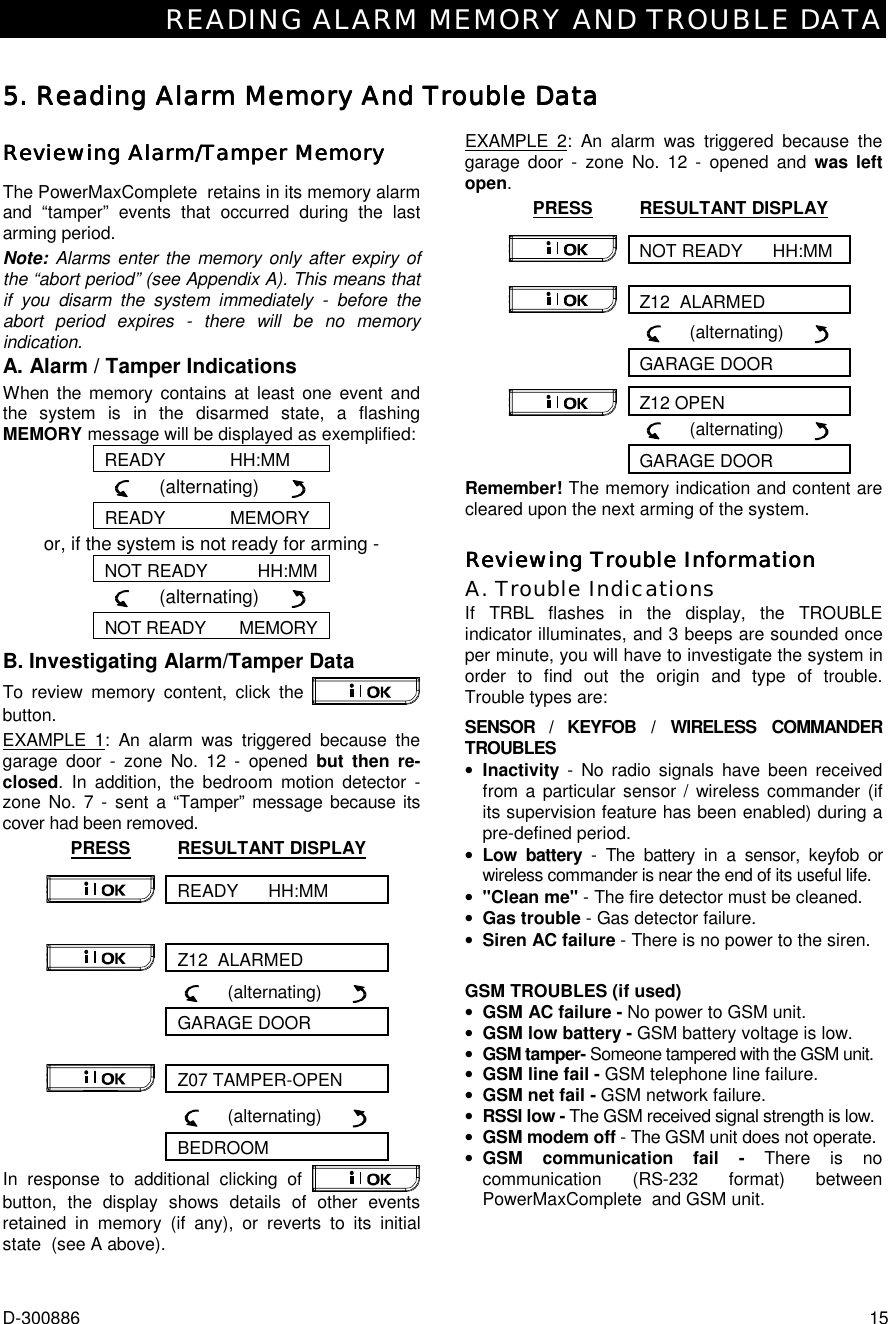
![SPECIAL FUNCTIONS 20 D-300886 Reporting Messages to a PagerReporting Messages to a PagerReporting Messages to a PagerReporting Messages to a Pager MPagerControlpanel Since the PowerMaxComplete can be programmed to report events to a pager, the user of the pager must be informed on how to interpret the numerical message that his pager displays. Communication with a pager takes place as follows: • The PowerMaxComplete dials the pager’s phone number, waits 5 seconds and sends the numerical message. • The message transmitted by the PowerMaxComplete to the pager is actually a string of digits, as follows: [XXXXXXXXXXXXXXXX][YYY][0ZZ#]Pager’s PIN No. - Up to 16 digitsProgrammed by the Installer Zone orUser No.Event Type Figure 6. Pager Message Structure The person receiving the message sees only the “YYY -0ZZ#” part of the message, which he can interpret by using the following legend: Events types (YYY) are coded as follows: Event Code Event Code Alarm 919 Fire 515 Trouble 818 Close 101 Emergency 717 Open 102 Panic 616 Latchkey 103 ZZ is the zone number in which the event occurred, or the user number in case of Close, Open and Latchkey events. Example 1: Message reads “919-003”: This means an alarm occurred in Zone No. 3. Example 2: Message reads “101-008”: This means the system was closed (armed) by user No. 8. Conducting a Walk TestConducting a Walk TestConducting a Walk TestConducting a Walk Test The walk test is an indispensable operation by which you verify that all detectors function properly, without disturbing the neighbors with loud sirens. The test must be performed at least once a week, and should include all detectors in all zones. Before performing walk test, all the detectors must be in normal state. Normal state is achieved when no motion is made for at least 2 minutes. Note: During the test period, 24-hour zones will not cause an alarm if violated, but a fire zone will function normally. A typical test will take place as follows: A. Press the test button . B. The display will prompt you for your user code: ENTER CODE _ _ _ _ C. Enter your code. The siren will sound for 2 seconds and the display will change to: TESTING D. Walk throughout the protected area and make sure you trigger every detector with no exception (move across the field of view of motion detectors and open/close doors and windows). Each time a detector is triggered: • The “Happy Tune” will sound, • The zone name and number will be displayed briefly, EXAMPLE 1: You triggered a motion detector in the living room (zone 11). The display will show: LIVING ROOM ! Z11 VIOLATED After 5 seconds the display will revert to: TESTING EXAMPLE 2: You opened a window in the guest room (zone 13). The display will show: GUEST ROOM ! Z13 OPEN After 5 seconds the display will revert to: TESTING E. When done, click the button repeatedly. The display will show the test results, zone after zone, in ascending numerical order. For example: GUEST ROOM (alternating) Z13 OK or: “Z13 NOT OK” if there was no response from Z13. F. To resume testing, click . To quit the test mode, click . The display will then read: <OK> TO EXIT G. Click . The display will revert to its normal state.](https://usermanual.wiki/Visonic/PWRMCOMPLETE.User-Manual/User-Guide-973248-Page-20.png)
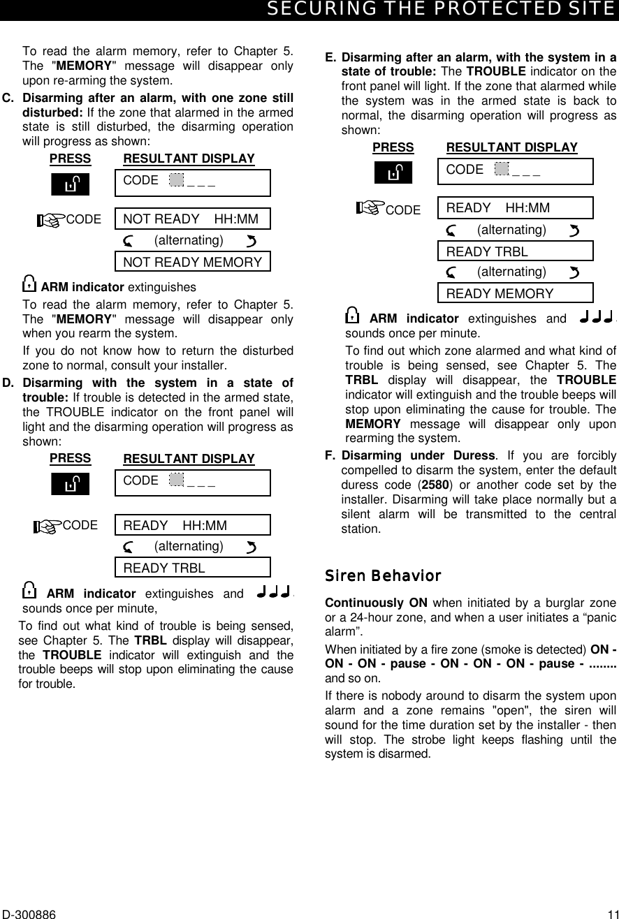
![USER SETTINGS D-300886 21 7. User Settings7. User Settings7. User Settings7. User Settings What are the Settings You Need?What are the Settings You Need?What are the Settings You Need?What are the Settings You Need? The installer provides you a ready-to-use alarm system, but a few settings and adjustments will still be needed. Note: Although the user settings are your responsibility, you may request your installer to perform them for you (except for the user codes, which you would like to keep secret). The user settings include: • Bypassing zones - determining which zones will be bypassed (disabled) during the present disarm period and the next armed period. • Reviewing the bypass list - "show bypass" - displaying the numbers and names of bypassed zone one by one. • Recalling the last bypassing scheme - "recall bypass" - re-using the previous bypassing scheme, which becomes suspended after disarming but is still saved in the PowerMaxComplete memory. • Programming the 4 telephone numbers* - determining the 1st, 2nd, 3rd and 4th telephone numbers to which the system will report event messages that were defined by the system installer. • Setting user codes* - programming a security code for yourself and additional 7 codes for other system users. Codes 5 through 8 are “Latchkey” user codes (see Chapter 2 - Arming in the Latchkey Mode for additional details). • Enrolling keyfob transmitters* - teaching the PowerMaxComplete system to recognize the ID code of each keyfob transmitter (multi-button, Code-Secure™ type, wireless transmitter), so that the PowerMaxComplete can respond to commands transmitted by them. • Enrolling proximity tags (optional) - Teaching the PowerMaxComplete to recognize the ID of each proximity tag so that the PowerMaxComplete can respond to proximity tags presentation. • Setting voice options* (not applicable in PowerMaxComplete that does not have VOICE feature) - Enabling or disabling verbal announcements (prompts). • Auto arm option* - enabling or disabling automatic arming (at a predefined time). • Setting auto arm time - selecting automatic arming time. • Using squawk option* - enabling/disabling LOW/MID/HI squawk (short siren sound) upon arming and disarming. All the options are applicable for wireless siren. For wired siren, refer to LOW, MID and HI options as "squawk enable". • Setting the time and time format* - adjusting the built-in clock to show the correct time and time format. • Setting the date and date format* - adjusting the built-in calendar date and date format. • Setting the scheduler* - setting schedule for devices start/stop activation. * This option can be accessed only if master user code has been entered. Entering the User Settings MenuEntering the User Settings MenuEntering the User Settings MenuEntering the User Settings Menu Figure 7 describes how to enter User Settings menu. 2Display in disarm state when allzones are secured (”00:00 orother digits show present time).1Instruction: click keyResultant displayInstruction: Enter 4-digit masteruser code (default “1111”), oruser code (see note below).43ENTER CODE _ _ _ _&&&READY 00:00NORMAL MODEUSER SETTINGS[master/ user code]&SHOW BYPASSRECALL BYPASSSET PHONE NUMBER'SET USER CODES'''(*)(*)SET BYPASSThese menu items are displayedonly if “bypass” was enabled bythe installer.'ENROLL KEYFOB(*)'ENROLL PROX TAG(*)'AUTO ARM OPTIONAUTO ARM TIMESQUAWK OPTIONSET TIME&FORMATSET DATE&FORMATSET VOICE OPTION''''(*)(*)(*)(*)(*)'(*)'SET VOICE OPTION is Notaplicable in PowerMax LE thatdoes not have VOICE feature.* Menu items that are markedwith an asterisk can beaccessed only if masteruser code has been entered.** INSTALLER MODE isdisplayed only if USERPERMIT ENABLE wasselected by the installer.Optional<OK> TO EXIT''(**)INSTALLER MODE(*)SCHEDULER(*) Figure 7 - Entering User Settings Menu The next paragraphs include User Settings instructions, step-by-step. However, if you want to get an overall view of the entire User Settings menu, refer to figure 8 - User Setting flow-chart. You can use the flow chart as your only guide along the user settings process, instead of going through the step-by-step instructions.](https://usermanual.wiki/Visonic/PWRMCOMPLETE.User-Manual/User-Guide-973248-Page-21.png)
![USER SETTINGS D-300886 23 Recalling the Last Bypass SchemeRecalling the Last Bypass SchemeRecalling the Last Bypass SchemeRecalling the Last Bypass Scheme Arming the alarm system with several zones in the bypassed state is in fact "partial arming". An identical partial arming may be repeated by recalling the last bypassing scheme (that was suspended and memorized upon disarming the system). Having entered your user code successfully (see above - Entering to the User Settings Menu), the display will read: SET BYPASS Click twice to change the display into: RECALL BYPASS At this point proceed as follows: ACTION RESULTANT DISPLAY <OK> TO RECALL RECALL BYPASS You may now select any other item on the USER SETTINGS menu or quit programming by clicking . When <OK> TO EXIT is displayed - click . Programming 4 Telephone NumbersProgramming 4 Telephone NumbersProgramming 4 Telephone NumbersProgramming 4 Telephone Numbers Here you determine the 1st, 2nd, 3rd and 4th telephone numbers to which the system will report event messages that were defined by the system installer. You can ask the installer to set part or all the four telephone numbers. Having entered your Master User Code successfully (see above - Entering the User Settings Menu), click button repeatedly (if necessary) until the display will read: SET PHONE NUMBER You are allowed to program the 4 numbers as follows: PRESS RESULTANT DISPLAY 1st private tel# XXXXXXXXX [Enter Tel. No.] XXXXXXXXX XXXXXXXXX 1st private tel# 2nd private tel# Continue the same way up to telephone number 4. You may now switch to any other item on the USER SETTINGS menu or quit programming by clicking until <OK> TO EXIT is displayed and then clicking . Setting the User CodesSetting the User CodesSetting the User CodesSetting the User Codes A maximum of eight 4-digit codes can be defined out of a total of (10)4 = 10000 user code possibilities. Having entered your Master User Code successfully (see above - Entering the User Settings Menu), click until the display reads: SET USER CODES User Code 1 replaces the factory default master user code, and should be assigned to the master user of the system. This code can not be erased. User Codes 2, 3 and 4 can be assigned to additional users - family members, co-workers etc. Codes 5 through 8 are assigned to “Latchkey Users” (see Chapter 2 - Arming in the Latchkey Mode, for an explanation of the latchkey mode). CAUTION! Code “0000” is not valid! Do not use it. Note: The duress code set by the installer (2580 by default) cannot be selected as a normal user code. Any attempt to program it will be rejected by the PowerMaxComplete. To program the codes, proceed as follows: PRESS RESULTANT DISPLAY user code 1: _ _ _ _ user code1: 0 0 0 0 user code 1: 6854 [4-digit user code] e.g. 6854) user code 1: 6854 user code 2 Continue the same way up to Code 8. user code 8: 5537 SET USER CODES You may now select any other item on the USER SETTINGS menu or quit programming by clicking . When <OK> TO EXIT is displayed - click .](https://usermanual.wiki/Visonic/PWRMCOMPLETE.User-Manual/User-Guide-973248-Page-23.png)
![USER SETTINGS 24 D-300886 RECALL BYPASS(5)SET PHONE NUMBER(1)SET USER CODES(1)AUTO ARM OPTIONAUTO ARM TIME(1)(1)SET VOICE OPTION(1)(6)ENROLL KEYFOB(1)'''''''ENROLL PROX TAG(1)'SHOW BYPASSSET BYPASSREADY 00:00(5)(5)''SQUAWK OPTIONSET TIME&FORMAT US FORMAT - 12H EU FORMAT - 24HTIME _ _:_ _A TIME _ _:_ _'[time] e.g. 07:55P '[time] e.g. 19:55DATE DD/MM/YYYY DATE MM/DD/YYYYSET DATE&FORMAT(1)(1)(1)(4)if not satisfied'if not satisfied''''''''''TIME 07:55 P TIME 19:55''squawk disablesqwk low volumesqwk mid volumesqwk hi volume(To review options, use or button)'Moving forwardMoving backwardMoving one levelup in the menuReturn to“<OK> TO EXIT”To move within most ofthe menus, the followingkeys can be used:Show / confirmdataDATE: _ _/_ _/_ _ _ _DATE:_ _/_ _/_ _ _ _'(date)(2)'(date)(2)''DATE 30/12/2000 DATE 12/30/2000''(e.g. 30/12/2000) (e.g. 12/30/2000)<OK> TO EXIT'(see detail “A”in next page)SCHEDULER''INSTALLER MODE(1)(1)<OK> TO RECALLuser code 1 0 0 0 0(for next user code 2,3....8)[code]user code 1 user code1(example)disable autoarm enable autoarm(if it is the current option)'[time]arm time _ _: _ _A(See format & example in“SET TIME&FORMAT” )enable prompts(if it is the current option)Keyfob No : TRANSMIT NOW KEYFOB No : 1''disable prompts disable promptsenable autoarmenter keyfob #for next (up) or previous (down) keyfob enrollment''''(press any key)''''1st private tel# 2nd private tel# 3rd private tel# 4th private tel#PRESENT TAG(for next prox tags 2,3....8)Tag no : 1(example)'Tag no : 1BYPASS LIST(3)NORMAL MODE<OK> TO BYPASS Z01: BYPASSEDZ01: OPENKITCHENAlternatingKITCHENAlternating(for checking stateof next zone)ENTER CODE _ _ _ _INSTALLER MODE(example)[4-digit master/user code]USER SETTINGS''&&Tel. No.&&&Tel. No.&&&Tel. No.&&&Tel. No.&if notsatisfiedif notsatisfied(First display isREADY / NOT READY)Entrance to INSTALLERMODE (described inthe installer guide)Optional Notes: (1) Function inside black rectangles are accessible only if master user code was entered. (2) For the year, enter the two last digits only. (3) Press to display the number, state and name of first bypassed zone. Press repeatedly to view all the bypassed zones. (4) To enter "A" (AM) press (or one of the 3 keys above it), to enter "P" (PM) press (or one of the 3 keys above it). (5) SET/SHOW/RECALL BYPASS menus are accessible only if "manual bypass has been selected by the installer. (6)Applicable in PowerMaxComplete that has VOICE feature - In the SET VOICE OPTION, if you select "enable prompts", the Control Panel mute speaker button is active. Figure 8 - Users Settings Flow Chart](https://usermanual.wiki/Visonic/PWRMCOMPLETE.User-Manual/User-Guide-973248-Page-24.png)
![USER SETTINGS D-300886 27 Note that the dark box at the far right has disappeared. It is now possible to enroll a new ID. It is also possible to leave the cleared zone or memory location free and simply exit to the main menu. Setting the VoSetting the VoSetting the VoSetting the Voice Optionsice Optionsice Optionsice Options (Not applicable in PowerMaxComplete that does not have VOICE option) Remember: Voice prompts are heard over the built-in loudspeaker subject to two conditions: - The voice option is enabled as shown below - The loudspeaker is enabled by pressing the “7” key (see Chapter 3 - Voice ON-OFF) Here you may select one of two options: Enable prompts: Voice announcements Disable prompts: No voice announcements The presently programmed option will be shown, with a dark selection box ( ) at the far right of the display. You may view the other option (that does not have a dark box at the far right) by clicking . A dark box will appear if you click while the other option is displayed. To set the voice option, proceed as follows: Having entered your Master User Code successfully (see above - Entering the User Settings Menu), click the button until the display reads: SET VOICE OPTIONS From here, proceed as follows: PRESS RESULTANT DISPLAY enable prompts (if this is the current option) disable prompts If not satisfied disable prompts If satisfied - SET VOICE OPTION You may now select any other item on the USER SETTINGS menu or quit programming by clicking . When <OK> TO EXIT is displayed - click . Note: When using the Model MCT-234 keyfob with the PowerMaxComplete, the voice prompts must be enabled. Automatic Arming OptionAutomatic Arming OptionAutomatic Arming OptionAutomatic Arming Option You can determine that the system will be automatically armed at any desired time. Having entered master user code successfully, click until AUTO ARM OPTION is displayed. From here, proceed as follows: PRESS RESULTANT DISPLAY enable autoarm (if this is the current option) disable autoarm If not satisfied press disable autoarm AUTO ARM OPTION You may now select any other item on USERS SETTINGS menu or quit programming process by clicking . When "<OK> TO EXIT" is displayed, click . Setting Arming TimeSetting Arming TimeSetting Arming TimeSetting Arming Time Having entered your Master User Code successfully (see above - Entering the User Settings Menu), click button (repeatedly, if necessary) until the display will read: AUTO ARM TIME From here, proceed as follows: PRESS RESULTANT DISPLAY arm time_ _ : _ _ A arm time 12:55 A [time digits] (e.g. 12:55 A) arm time 12:55 A AUTO ARM TIME Notes: 1. For 12h/24h time format selection, refer to Setting Time and Time Format below. 2. Press "(" to enter A (AM), or press "#" to enter P (PM). Enabling the Squawk OptionEnabling the Squawk OptionEnabling the Squawk OptionEnabling the Squawk Option You can determine that the system will activate (or not activate) high/mid/low siren sound, for a short time, upon arming (1 beep) and disarming (2 beeps), by keyfob only. Having entered your Master User Code successfully (see above - Entering the User Settings Menu), click the button (repeatedly, if necessary) until the display will read: SQUAWK OPTION](https://usermanual.wiki/Visonic/PWRMCOMPLETE.User-Manual/User-Guide-973248-Page-27.png)
![USER SETTINGS 28 D-300886 From here, proceed as follows: PRESS RESULTANT DISPLAY squawk disable (if this is the current option) squawk low volume If not satisfied - squawk mid volume If not satisfied - squawk hi volume If not satisfied squawk hi volume If satisfied For wired siren, refer to "low", "mid" and "hi" options as "squawk enable". You may now select any other item on the USERS SETTINGS menu or quit the programming process by clicking . When "<OK> TO EXIT" is displayed, click . Setting Time and Time FormatSetting Time and Time FormatSetting Time and Time FormatSetting Time and Time Format Having entered your Master User Code successfully (see Entering the User Settings Menu, above), click until the display reads: SET TIME&FORMAT A. If 12h format is desired, continue as follows: PRESS RESULTANT DISPLAY US FORMAT - 12H (if this is the current option) TIME _ _ : _ _ A TIME 12:55A (time digits] (e.g. 12:55A) TIME HH:MM A Note: To enter “A” - press [(] or to enter “P” - press [#]. B. If 24h format is desired, continue as follows: PRESS RESULTANT DISPLAY US FORMAT - 12H EU FORMAT - 24H TIME _ _ : _ _ TIME 19:55 [time digits] (e.g. 19:55) TIME 19:55 TIME HH:MM You may now select any other item on the USER SETTINGS menu or quit programming by clicking . When <OK> TO EXIT is displayed - click . Setting tSetting tSetting tSetting the Date and Date Formathe Date and Date Formathe Date and Date Formathe Date and Date Format Having entered your Master User Code successfully (see above - Entering the User Settings Menu), click button (repeatedly, if necessary) until the display will read SET DATE&FORMAT. From here, proceed as follows: PRESS RESULTANT DISPLAY DATE MM/DD/YYYY DATE DD/MM/YYYY If not satisfied press DATE _ _ / _ _ /_ _ _ _ DATE 01/01/2002 [Enter date] (e.g. 01/01/2002) DATE 01/01/2002 DATE DD/MM/YYYY You may now select any other item on the USER SETTINGS menu or quit programming by clicking . When <OK> TO EXIT is displayed - click .](https://usermanual.wiki/Visonic/PWRMCOMPLETE.User-Manual/User-Guide-973248-Page-28.png)