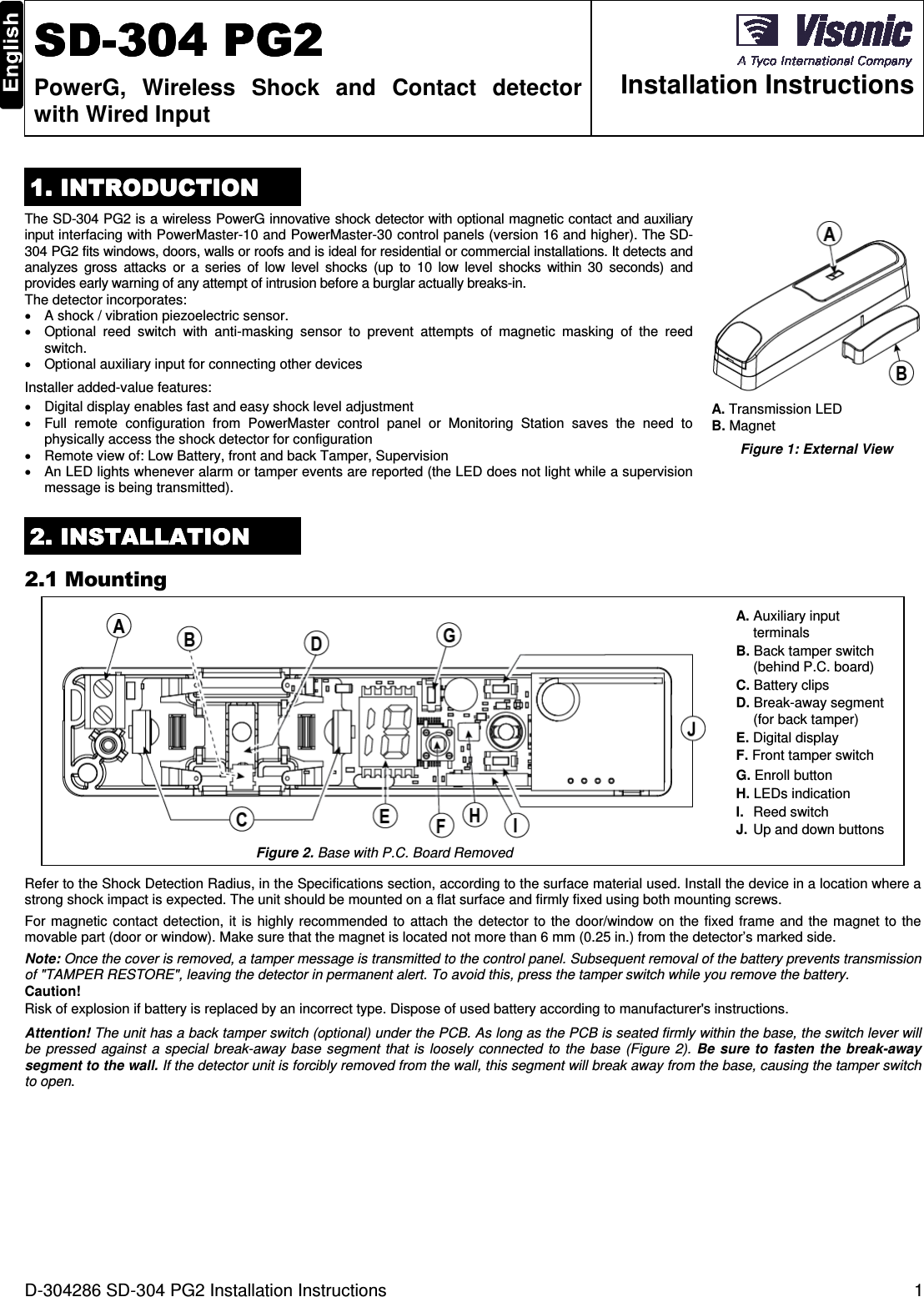
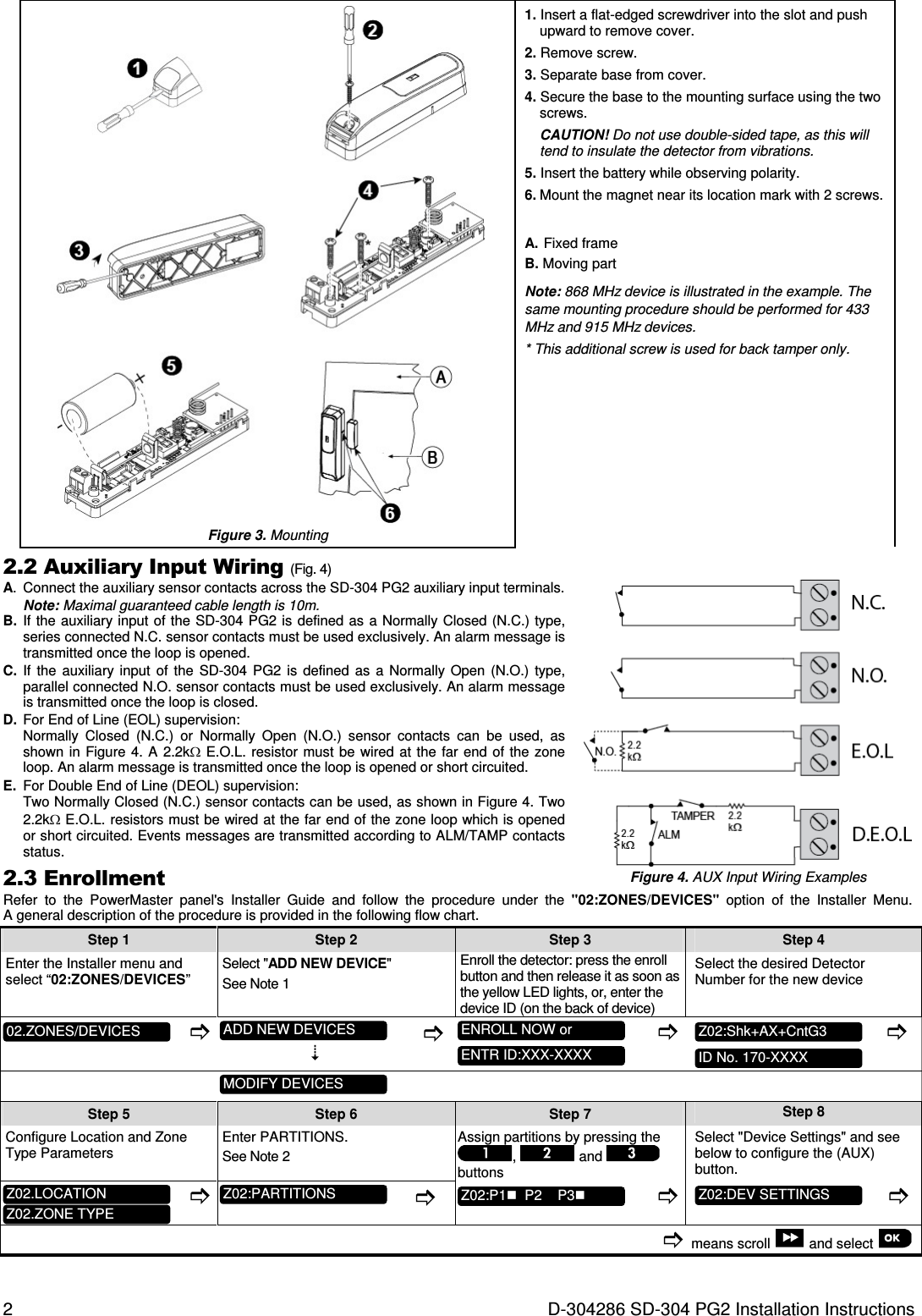
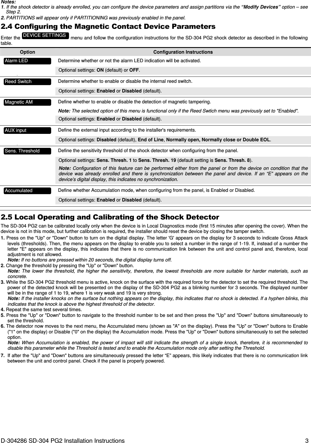
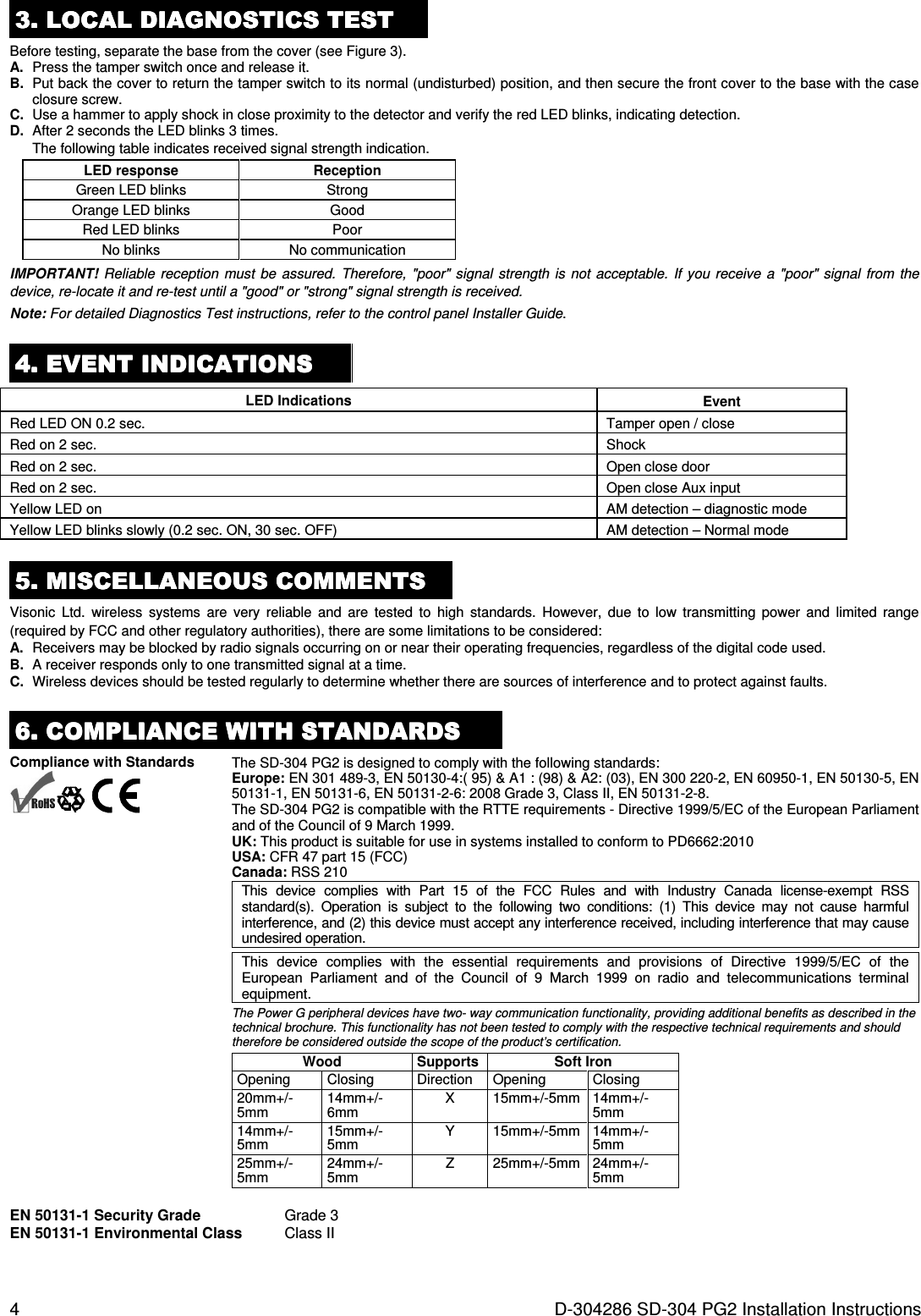
Visonic SD304CPG2 SHOCK DETECTOR User Manual D 304286 SD 304 PG2 Installation Instructions

Visonic Ltd. SHOCK DETECTOR D 304286 SD 304 PG2 Installation Instructions

User Manual

D-304286 SD-304 PG2 Installation Instructions  1  SDSDSDSD----304 PG2304 PG2304 PG2304 PG2    PowerG,  Wireless  Shock  and  Contact  detector with Wired Input  Installation Instructions 1. INTRODUCTION1. INTRODUCTION1. INTRODUCTION1. INTRODUCTION    The SD-304 PG2 is a wireless PowerG innovative shock detector with optional magnetic contact and auxiliary input interfacing with PowerMaster-10 and PowerMaster-30 control panels (version 16 and higher). The SD-304 PG2 fits windows, doors, walls or roofs and is ideal for residential or commercial installations. It detects and analyzes  gross  attacks  or  a  series  of  low  level  shocks  (up  to  10  low  level  shocks  within  30  seconds)  and provides early warning of any attempt of intrusion before a burglar actually breaks-in. The detector incorporates: •  A shock / vibration piezoelectric sensor. •  Optional  reed  switch  with  anti-masking  sensor  to  prevent  attempts  of  magnetic  masking  of  the  reed switch. •  Optional auxiliary input for connecting other devices  Installer added-value features: •  Digital display enables fast and easy shock level adjustment •  Full  remote  configuration  from  PowerMaster  control  panel  or  Monitoring  Station  saves  the  need  to physically access the shock detector for configuration  •  Remote view of: Low Battery, front and back Tamper, Supervision •  An LED lights whenever alarm or tamper events are reported (the LED does not light while a supervision message is being transmitted).  A. Transmission LED  B. Magnet Figure 1: External View 2222. INSTALLATION. INSTALLATION. INSTALLATION. INSTALLATION    2.1 Mounting  A. Auxiliary input terminals B. Back tamper switch (behind P.C. board)  C. Battery clips D. Break-away segment (for back tamper) E. Digital display F. Front tamper switch G. Enroll button H. LEDs indication  I.  Reed switch J.  Up and down buttons Figure 2. Base with P.C. Board Removed Refer to the Shock Detection Radius, in the Specifications section, according to the surface material used. Install the device in a location where a strong shock impact is expected. The unit should be mounted on a flat surface and firmly fixed using both mounting screws. For magnetic contact  detection, it  is  highly  recommended  to attach the  detector  to the  door/window on  the fixed frame and  the  magnet to  the movable part (door or window). Make sure that the magnet is located not more than 6 mm (0.25 in.) from the detector’s marked side. Note: Once the cover is removed, a tamper message is transmitted to the control panel. Subsequent removal of the battery prevents transmission of "TAMPER RESTORE", leaving the detector in permanent alert. To avoid this, press the tamper switch while you remove the battery. Caution! Risk of explosion if battery is replaced by an incorrect type. Dispose of used battery according to manufacturer's instructions. Attention! The unit has a back tamper switch (optional) under the PCB. As long as the PCB is seated firmly within the base, the switch lever will be  pressed  against  a  special  break-away  base  segment  that  is  loosely  connected  to  the base (Figure  2).  Be sure  to  fasten  the break-away segment to the wall. If the detector unit is forcibly removed from the wall, this segment will break away from the base, causing the tamper switch to open.
2  D-304286 SD-304 PG2 Installation Instructions  Figure 3. Mounting 1. Insert a flat-edged screwdriver into the slot and push upward to remove cover. 2. Remove screw. 3. Separate base from cover. 4. Secure the base to the mounting surface using the two screws. CAUTION! Do not use double-sided tape, as this will tend to insulate the detector from vibrations. 5. Insert the battery while observing polarity. 6. Mount the magnet near its location mark with 2 screws. A.  Fixed frame B. Moving part Note: 868 MHz device is illustrated in the example. The same mounting procedure should be performed for 433 MHz and 915 MHz devices. * This additional screw is used for back tamper only. 2.2 Auxiliary Input Wiring (Fig. 4) A.  Connect the auxiliary sensor contacts across the SD-304 PG2 auxiliary input terminals. Note: Maximal guaranteed cable length is 10m.  B.  If the  auxiliary input of the SD-304 PG2 is defined as a Normally Closed (N.C.) type, series connected N.C. sensor contacts must be used exclusively. An alarm message is transmitted once the loop is opened. C.  If  the  auxiliary  input  of  the  SD-304  PG2  is  defined  as  a  Normally Open  (N.O.)  type, parallel connected N.O. sensor contacts must be used exclusively. An alarm message is transmitted once the loop is closed. D.  For End of Line (EOL) supervision: Normally  Closed  (N.C.)  or  Normally  Open  (N.O.)  sensor  contacts  can  be  used,  as shown in  Figure  4. A  2.2kΩ  E.O.L. resistor  must  be wired  at the  far  end of the  zone loop. An alarm message is transmitted once the loop is opened or short circuited. E.  For Double End of Line (DEOL) supervision: Two Normally Closed (N.C.) sensor contacts can be used, as shown in Figure 4. Two 2.2kΩ E.O.L. resistors must be wired at the far end of the zone loop which is opened or short circuited. Events messages are transmitted according to ALM/TAMP contacts status. 2.3 Enrollment  Figure 4. AUX Input Wiring Examples Refer  to  the  PowerMaster  panel's  Installer  Guide  and  follow  the  procedure  under  the  "02:ZONES/DEVICES"  option  of  the  Installer  Menu. A general description of the procedure is provided in the following flow chart. Step 1 Step 2 Step 3 Step 4   Enter the Installer menu and select “02:ZONES/DEVICES” Select "ADD NEW DEVICE"  See Note 1 Enroll the detector: press the enroll button and then release it as soon as the yellow LED lights, or, enter the device ID (on the back of device) Select the desired Detector Number for the new device                  Step 5 Step 6 Step 7 Step 8 Configure Location and Zone Type Parameters Enter PARTITIONS. See Note 2 Assign partitions by pressing the ,   and   buttons Select "Device Settings" and see below to configure the (AUX) button.               means scroll   and select   Z02:DEV SETTINGS  Z02:P1  P2    P3  Z02:PARTITIONS  Z02.ZONE TYPE  Z02.LOCATION  ID No. 170-XXXX  Z02:Shk+AX+CntG3  ENTR ID:XXX-XXXX  ENROLL NOW or  MODIFY DEVICES  ADD NEW DEVICES  02.ZONES/DEVICES
D-304286 SD-304 PG2 Installation Instructions  3 Notes: 1. If the shock detector is already enrolled, you can configure the device parameters and assign partitions via the “Modify Devices” option – see Step 2. 2. PARTITIONS will appear only if PARTITIONING was previously enabled in the panel. 2.4 Configuring the Magnetic Contact Device Parameters Enter the   menu and follow the configuration instructions for the SD-304 PG2 shock detector as described in the following table. Option  Configuration Instructions   Determine whether or not the alarm LED indication will be activated. Optional settings: ON (default) or OFF. •     Determine whether to enable or disable the internal reed switch. Optional settings: Enabled or Disabled (default).     Define whether to enable or disable the detection of magnetic tampering. Note: The selected option of this menu is functional only if the Reed Swtich menu was previously set to "Enabled". Optional settings: Enabled or Disabled (default).     Define the external input according to the installer's requirements. Optional settings: Disabled (default), End of Line, Normally open, Normally close or Double EOL. •     Define the sensitivity threshold of the shock detector when configuring from the panel. Optional settings: Sens. Thresh. 1 to Sens. Thresh. 19 (default setting is Sens. Thresh. 8). Note: Configuration of  this  feature  can  be performed  either  from the  panel or  from the  device  on  condition  that the device  was  already  enrolled  and  there  is  synchronization  between  the  panel  and  device.  If  an  “E”  appears  on  the device’s digital display, this indicates no synchronization.     Define whether Accumulation mode, when configuring from the panel, is Enabled or Disabled. Optional settings: Enabled or Disabled (default).         2.5 Local Operating and Calibrating of the Shock Detector The SD-304 PG2 can be calibrated locally only when the device is in Local Diagnostics mode (first 15 minutes after opening the cover). When the device is not in this mode, but further calibration is required, the installer should reset the device by closing the tamper switch. 1. Press on the "Up" or "Down" button to turn on the digital display. The letter 'G' appears on the display for 3 seconds to indicate Gross Attack levels (thresholds). Then, the menu appears on the display to enable you to select a number in the range of 1-19. If, instead of a number the letter "E"  appears on  the display, this indicates  that there is no communication  link between the unit and control panel  and, therefore, local adjustment is not allowed.  Note: If no buttons are pressed within 20 seconds, the digital display turns off.  2. Change the threshold by pressing the "Up" or "Down" button.  Note:  The  lower  the  threshold,  the  higher  the  sensitivity,  therefore,  the  lowest  thresholds  are  more  suitable  for  harder  materials,  such  as concrete. 3. While the SD-304 PG2 threshold menu is active, knock on the surface with the required force for the detector to set the required threshold. The power of the detected knock will be presented on the display of the SD-304 PG2 as a blinking number for 3 seconds. The displayed number will be in the range of 1 to 19, where 1 is very weak and 19 is very strong. Note: If the installer knocks on the surface but nothing appears on the display, this indicates that no shock is detected. If a hyphen blinks, this indicates that the knock is above the highest threshold of the detector. 4. Repeat the same test several times. 5. Press the "Up" or "Down" button to navigate to the threshold number to be set and then press the "Up" and "Down" buttons simultaneously to set the threshold. 6. The detector now moves to the next menu, the Accumulated menu (shown as "A" on the display). Press the "Up" or "Down" buttons to Enable ("1" on the display) or Disable ("0" on the display) the Accumulation mode. Press the "Up" or "Down" buttons simultaneously to set the selected option. Note: When Accumulation  is  enabled,  the power  of impact  will  still  indicate  the strength  of  a single knock,  therefore, it is  recommended to disable this parameter while the Threshold is tested and to enable the Accumulation mode only after setting the Threshold. 7.  If after the "Up" and "Down" buttons are simultaneously pressed the letter “E” appears, this likely indicates that there is no communication link between the unit and control panel. Check if the panel is properly powered.  Sens. Threshold Magnetic AM Reed Switch  Alarm LED Accumulated AUX input DEVICE SETTINGS
4  D-304286 SD-304 PG2 Installation Instructions 3333. . . . LOCAL DIAGNOSTICS TESTLOCAL DIAGNOSTICS TESTLOCAL DIAGNOSTICS TESTLOCAL DIAGNOSTICS TEST    Before testing, separate the base from the cover (see Figure 3). A.  Press the tamper switch once and release it.  B.  Put back the cover to return the tamper switch to its normal (undisturbed) position, and then secure the front cover to the base with the case closure screw. C.  Use a hammer to apply shock in close proximity to the detector and verify the red LED blinks, indicating detection. D.  After 2 seconds the LED blinks 3 times.  The following table indicates received signal strength indication. LED response Reception  Green LED blinks Strong  Orange LED blinks Good  Red LED blinks Poor  No blinks No communication IMPORTANT! Reliable reception must  be  assured.  Therefore,  "poor"  signal strength  is not  acceptable.  If  you  receive  a  "poor" signal from  the device, re-locate it and re-test until a "good" or "strong" signal strength is received. Note: For detailed Diagnostics Test instructions, refer to the control panel Installer Guide. 4. E4. E4. E4. EVENT INDICATIONSVENT INDICATIONSVENT INDICATIONSVENT INDICATIONS    LED Indications  Event Red LED ON 0.2 sec.  Tamper open / close Red on 2 sec.  Shock  Red on 2 sec.  Open close door  Red on 2 sec.  Open close Aux input  Yellow LED on   AM detection – diagnostic mode Yellow LED blinks slowly (0.2 sec. ON, 30 sec. OFF)  AM detection – Normal mode 5555. . . . MISCELLANEOUS COMMENTSMISCELLANEOUS COMMENTSMISCELLANEOUS COMMENTSMISCELLANEOUS COMMENTS    Visonic  Ltd.  wireless  systems  are  very  reliable  and  are  tested  to  high  standards.  However,  due  to  low  transmitting  power  and  limited  range (required by FCC and other regulatory authorities), there are some limitations to be considered: A.  Receivers may be blocked by radio signals occurring on or near their operating frequencies, regardless of the digital code used. B.  A receiver responds only to one transmitted signal at a time. C.  Wireless devices should be tested regularly to determine whether there are sources of interference and to protect against faults. 6666. . . . COMPLIANCE WITH STANDARDSCOMPLIANCE WITH STANDARDSCOMPLIANCE WITH STANDARDSCOMPLIANCE WITH STANDARDS    Compliance with Standards The SD-304 PG2 is designed to comply with the following standards:       Europe: EN 301 489-3, EN 50130-4:( 95) & A1 : (98) & A2: (03), EN 300 220-2, EN 60950-1, EN 50130-5, EN 50131-1, EN 50131-6, EN 50131-2-6: 2008 Grade 3, Class II, EN 50131-2-8. The SD-304 PG2 is compatible with the RTTE requirements - Directive 1999/5/EC of the European Parliament and of the Council of 9 March 1999. UK: This product is suitable for use in systems installed to conform to PD6662:2010  USA: CFR 47 part 15 (FCC) Canada: RSS 210 This  device  complies  with  Part  15  of  the  FCC  Rules  and  with  Industry  Canada  license-exempt  RSS standard(s).  Operation  is  subject  to  the  following  two  conditions:  (1)  This  device  may  not  cause  harmful interference, and (2) this device must accept any interference received, including interference that may cause undesired operation. This  device  complies  with  the  essential  requirements  and  provisions  of  Directive  1999/5/EC  of  the European  Parliament  and  of  the  Council  of  9  March  1999  on  radio  and  telecommunications  terminal equipment. The Power G peripheral devices have two- way communication functionality, providing additional benefits as described in the technical brochure. This functionality has not been tested to comply with the respective technical requirements and should therefore be considered outside the scope of the product’s certification. Wood Supports Soft Iron Opening  Closing  Direction  Opening  Closing 20mm+/-5mm 14mm+/-6mm X  15mm+/-5mm 14mm+/-5mm 14mm+/-5mm 15mm+/-5mm Y  15mm+/-5mm 14mm+/-5mm 25mm+/-5mm 24mm+/-5mm Z  25mm+/-5mm 24mm+/-5mm   EN 50131-1 Security Grade  Grade 3 EN 50131-1 Environmental Class  Class II
D-304286 SD-304 PG2 Installation Instructions  5 FCC Compliance Statement The digital circuitry of this device has been tested and found to comply with the limits for a Class B digital device, pursuant to Part 15 of the FCC Rules.  These  limits  are  designed  to  provide  reasonable  protection  against  harmful  interference  in  residential  installations.  This  equipment generates, uses and can  radiate radio  frequency energy and,  if not installed and  used in  accordance with  the instructions,  may cause  harmful interference  to  radio  and  television  reception. However,  there  is  no  guarantee  that interference will  not  occur  in  a particular installation. If  this device does cause such interference, which can be verified by turning the device off and on, the user is encouraged to eliminate the interference by one or more of the following measures: –  Re-orient or re-locate the receiving antenna. –  Increase the distance between the device and the receiver. –  Connect the device to an outlet on a circuit different from the one which supplies power to the receiver. – Consult the dealer or an experienced radio/TV technician IC statement: This device complies with Part 15 of the FCC Rules and with Industry Canada license-exempt RSS standard(s). Operation is subject to the following two conditions: (1) this device may not cause interference, and (2) this device must accept any interference, including interference that may cause undesired operation of the device. Le present appareil est conforme aux CNR d'Industrie Canada applicables aux appareils radio exempts de licence. L'exploitation est autorisee aux deux conditions suivantes :(1) l'appareil ne doit pas produire de brouillage, et (2) l'utilisateur de l'appareil doit accepter tout brouillage radioelectrique subi, meme si le brouillage est susceptible d'en compromettre le fonctionnement. WARNING!  To comply with FCC and IC RF exposure compliance requirements, the device should be located at a distance of at least 20 cm from all persons during  normal  operation.  The  antennas  used  for  this  product  must  not  be  co-located  or  operated  in  conjunction  with  any  other  antenna  or transmitter. WARNING!  The user is cautioned that changes or modifications to the unit, not expressly approved by Visonic Ltd., could void the user’s FCC or other authority to operate the equipment.  The technical documentation as required by the European Conformity Assessment procedure is kept at:  UNIT 6 MADINGLEY COURT CHIPPENHAM DRIVE KINGSTON MILTON KEYNES MK10 0BZ. TEL.: +44(0)845 0755800  FAX: +44(0)845 0755801   W.E.E.E. Product Recycling Declaration For   information regarding  the recycling   of  this product  you  must  contact  the  company from  which you orignially purchased  it. If you are  discarding this product and not returning it for repair then you must ensure that it is returned as identified by your supplier. This product is not to be thrown away with everyday waste. Directive 2002/96/EC Waste Electrical and Electronic Equipment. APPENDIXAPPENDIXAPPENDIXAPPENDIX::::    SPECIFICATIONSSPECIFICATIONSSPECIFICATIONSSPECIFICATIONS    Frequency Band (MHz) Europe and rest of world: 433-434, 868-869 USA: 912-919 Communication Protocol PowerG Alarm Input One auxiliary Tamper Front and back Supervision Signaling at 4-min. intervals Tamper Alert Reported when a tamper event occurs Power Supply Type C Battery type 3 V Lithium CR-123A type battery, Panasonic, Sanyo or GP only. Battery Life Expectancy 5 years (for typical use) with all sensors enabled Shock Detection Radius Window  4m PVC double glass TBD Wood  3.5m Brick/concrete walls 2.5m  Operating Temperature -10°C to 55°C (14°F to 131°F) Storage Temperature -20°C to 60°C (-4°F to 140°F) Humidity Average relative humidity of approximate 75% non-condensing. For 30 days per year relative humidity may vary between 85 % and 95 % non-condensing Auxiliary Input Cable Length 10m max. Auxiliary Input EOL Resistor 2.2 KΩ Dimensions (LxWxD) 118 x 27 x 30 mm (4-5/8 x 1-1/8 x 1-3/16 in.) Weight (including battery) 130g (4.6 oz)
6  D-304286 SD-304 PG2 Installation Instructions WARRANTY  Visonic Limited (the “Manufacturer") warrants this product only (the "Product") to the original purchaser only (the “Purchaser”) against defective workmanship and materials under normal use of the Product for a period of twelve (12) months from the date of shipment by the Manufacturer.   This Warranty is absolutely conditional upon the Product having been properly installed, maintained and operated under  conditions of  normal use  in accordance  with the  Manufacturers  recommended installation and  operation instructions.    Products  which  have  become  defective  for  any  other  reason,  according  to  the  Manufacturers discretion, such as  improper installation, failure to  follow recommended installation and operational instructions, neglect,  willful  damage,  misuse  or  vandalism,  accidental  damage,  alteration or  tampering,  or  repair  by anyone other than the manufacturer, are not covered by this Warranty. The Manufacturer does not represent that this Product may not be compromised and/or circumvented or that the Product will prevent any death and/or personal injury and/or damage  to property resulting from burglary, robbery, fire  or  otherwise,  or  that  the  Product  will  in  all  cases  provide  adequate  warning  or  protection.      The  Product, properly installed and maintained, only reduces the risk of such events without warning and it is not a guarantee or insurance that such events will not occur.  THIS WARRANTY IS EXCLUSIVE AND EXPRESSLY IN LIEU OF ALL OTHER WARRANTIES, OBLIGATIONS OR  LIABILITIES, WHETHER  WRITTEN,  ORAL, EXPRESS  OR IMPLIED,  INCLUDING  ANY WARRANTY OF MERCHANTABILITY OR FITNESS FOR A PARTICULAR PURPOSE, OR OTHERWISE.  IN NO CASE SHALL THE MANUFACTURER BE LIABLE TO ANYONE FOR ANY CONSEQUENTIAL OR INCIDENTAL DAMAGES FOR BREACH OF THIS WARRANTY OR ANY OTHER WARRANTIES WHATSOEVER, AS AFORESAID. THE  MANUFACTURER  SHALL  IN  NO  EVENT  BE  LIABLE  FOR  ANY  SPECIAL,  INDIRECT,  INCIDENTAL, CONSEQUENTIAL  OR PUNITIVE  DAMAGES OR  FOR LOSS,  DAMAGE, OR EXPENSE,  INCLUDING LOSS OF  USE,  PROFITS,  REVENUE,  OR  GOODWILL,  DIRECTLY  OR  INDIRECTLY  ARISING  FROM PURCHASER’S  USE  OR  INABILITY  TO  USE  THE  PRODUCT,  OR  FOR  LOSS  OR  DESTRUCTION  OF OTHER PROPERTY OR FROM ANY OTHER CAUSE, EVEN IF MANUFACTURER HAS BEEN ADVISED OF THE POSSIBILITY OF SUCH DAMAGE. THE  MANUFACTURER  SHALL  HAVE  NO  LIABILITY  FOR  ANY  DEATH,  PERSONAL  AND/OR  BODILY INJURY AND/OR DAMAGE TO PROPERTY OR OTHER LOSS WHETHER DIRECT, INDIRECT, INCIDENTAL, CONSEQUENTIAL OR OTHERWISE, BASED ON A CLAIM THAT THE PRODUCT FAILED TO FUNCTION.  However, if the Manufacturer is held liable, whether directly or indirectly, for any loss or damage arising under this limited warranty, THE MANUFACTURER'S MAXIMUM LIABILITY (IF ANY) SHALL NOT IN ANY CASE EXCEED THE PURCHASE PRICE OF THE PRODUCT, which shall be fixed as liquidated damages and not as a penalty, and shall be the complete and exclusive remedy against the Manufacturer.  When accepting the delivery of the Product, the Purchaser agrees to the said conditions of sale and warranty and he recognizes having been informed of. Some jurisdictions do not allow the exclusion or limitation of incidental or consequential damages, so these limitations may not apply under certain circumstances.  The Manufacturer shall be under no liability whatsoever arising out of the corruption and/or malfunctioning of any telecommunication or electronic equipment or any programs. The  Manufacturers  obligations  under  this  Warranty  are  limited  solely  to  repair  and/or  replace  at  the Manufacturer’s  discretion any Product or  part  thereof that  may prove defective.  Any repair and/or  replacement shall not extend the original Warranty  period.   The Manufacturer shall not be responsible for dismantling and/or reinstallation costs.  To exercise this Warranty the Product must be returned to the Manufacturer freight pre-paid and insured.   All freight  and  insurance  costs are the responsibility of the Purchaser and are not included in this Warranty. This warranty shall not be modified, varied or extended, and the Manufacturer does not authorize any person to act  on  its  behalf  in  the  modification,  variation  or  extension  of  this  warranty.  This  warranty  shall  apply  to  the Product only.  All products, accessories or attachments of others used in conjunction with the Product, including batteries,  shall  be  covered  solely  by  their  own  warranty,  if  any.    The  Manufacturer  shall  not  be  liable  for  any damage or loss whatsoever, whether directly, indirectly, incidentally, consequentially or otherwise, caused by the malfunction  of  the  Product due  to  products, accessories,  or  attachments  of others,  including  batteries,  used  in conjunction with the Products. This Warranty is exclusive to the original Purchaser and is not assignable.  This  Warranty  is  in  addition  to  and  does  not  affect  your  legal  rights.  Any  provision  in  this  warranty  which  is contrary to the Law in the state or country were the Product is supplied shall not apply.  Warning: The user must follow the Manufacturer’s installation and operational instructions including testing the Product and its whole system at least once a week and to take all necessary precautions for his/her safety and the protection of his/her property. 1/08                                                                EMAIL: info@visonic.com INTERNET: www.visonic.com VISONIC LTD. 2012      D-304286  SD-304 PG2  (Rev 2, 12/12)

Navigation menu