Visonic SR730PG2 Wireless outdoor siren User Manual User manual 21126
Visonic Ltd. Wireless outdoor siren User manual 21126
UserManual.wiki
>
Visonic
>
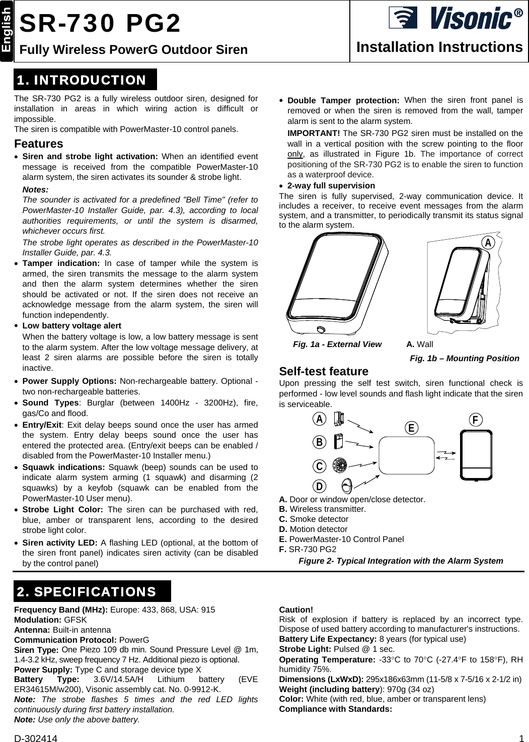
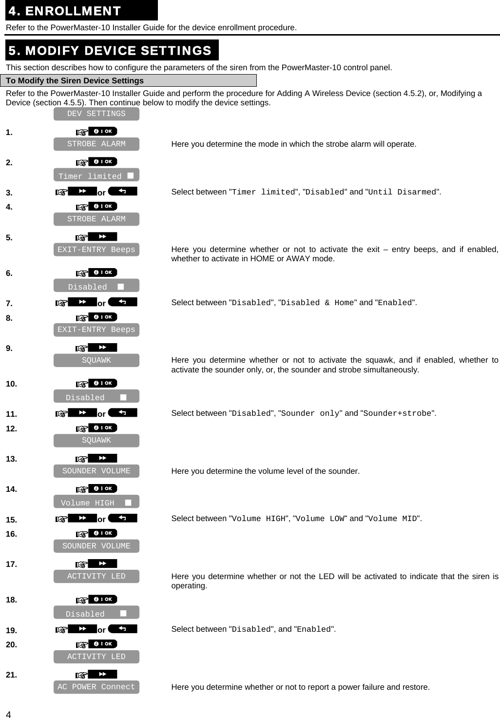
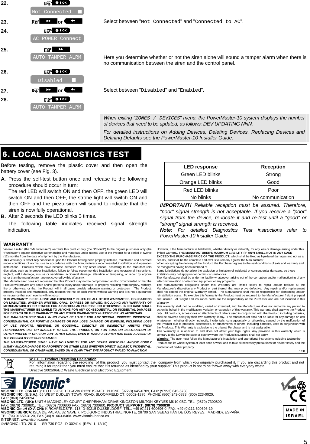
SR730PG2 User Manual
manual
Navigation menu
Upload a User Manual
Namespaces
Wiki Guide
HTML
PDF
Info
Views
User Manual
Discussion / Help
Navigation