Visonic TMD560PG2 Temperature detector User Manual D 303471 TMD 560 PG2 Installation Instructions
Visonic Ltd. Temperature detector D 303471 TMD 560 PG2 Installation Instructions
UserManual.wiki
>
Visonic
>
TMD560PG2 User Manual
manual
Navigation menu
Upload a User Manual
Namespaces
Wiki Guide
HTML
PDF
Info
Views
User Manual
Discussion / Help
Navigation
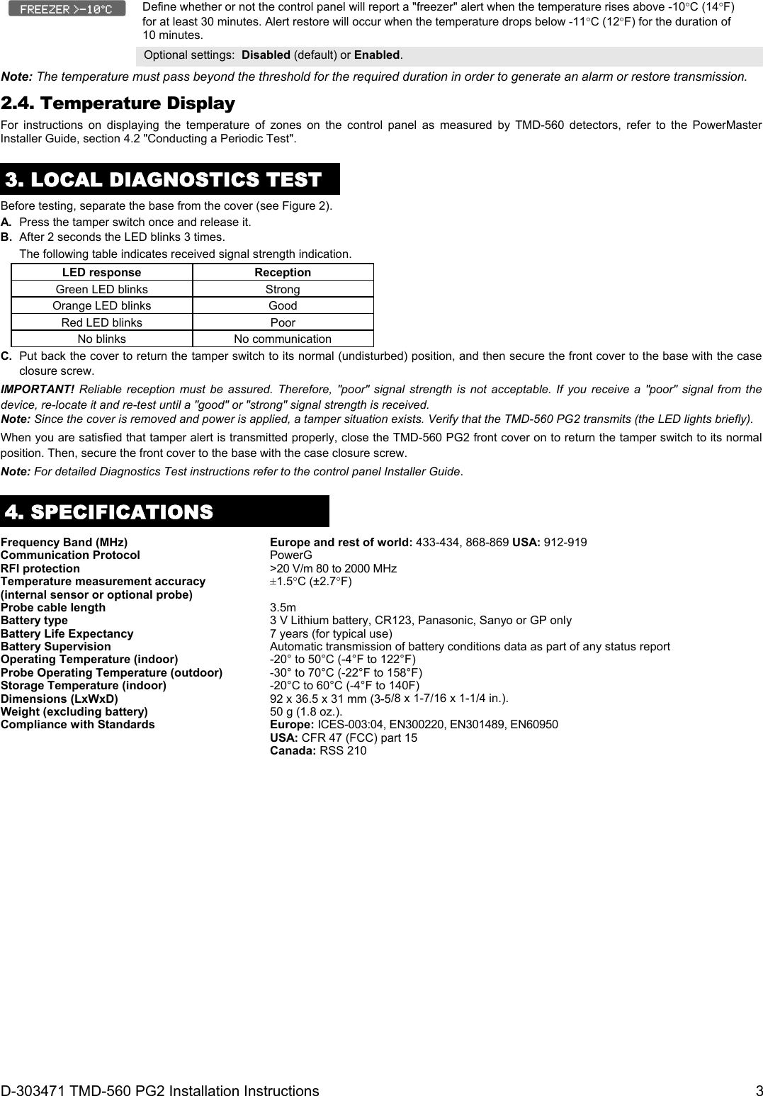
![2 D-303471 TMD-560 PG2 Installation Instructions Figure 2. Mounting Figure 3. Temperature Probe Mounting 1. Insert a flat-edged screwdriver into the slot and push upward to remove cover. 2. Remove screw. 3. Separate base from cover. 4. Flex catch and remove P.C. board. 5. Mark and drill 2 holes in the mounting surface. Fasten base with 2 countersunk screws. 6. Reinsert P.C. board into base and connect the two wires of the probe to the terminal block. A. Terminal Jumper B. Enroll button C. LED D. Internal Temperature Sensor 2.2. Enrollment Refer to the PowerMaster panel's Installer Guide and follow the procedure under the "02:ZONES/DEVICES" option of the Installer Menu. A general description of the procedure is provided in the following flow chart. Step 1 Step 2 Step 3 Step 4 Step 5 Step 6Enter the Installer menu and select “02:ZONES/DEVICES” Select "ADD NEW DEVICE" Option See Note [1] Enroll the device or Enter the device ID Select the desired Zone Number Configure Location, Zone Type & Chime Parameters Configure the Detector means scroll and select See Note [2] Notes: [1] If the temperature detector device is already enrolled you can configure the temperature detector device parameters via the “Modify Devices” option – see Step 2. [2] Select the "Device Settings" option and refer to section 2.3 to configure the temperature detector device parameters. 2.3. Configuring the Temperature Device Parameters Enter the menu and follow the configuration instructions for the TMD-560 PG2 temperature detector device as described in the following table. Option Configuration Instructions Set the detector to detect temperatures in either Celsius or Fahrenheit. Optional settings: Celsius C (default) or Fahrenheit F. Define whether or not the control panel will report a "very hot" alert when the temperature rises above 35C (95F) for at least 10 minutes. Alert restore will occur when the temperature drops below 34C (93F) for the duration of 10 minutes. Optional settings: Disabled (default) or Enabled. Define whether or not the control panel will report a "cold" alert when the temperature drops below 19C (66F) for at least 10 minutes. Alert restore will occur when the temperature rises above 20C (68F) for the duration of 10 minutes. Optional settings: Disabled (default) or Enabled. Define whether or not the control panel will report a "freezing" alert when the temperature drops below 7C (45F) for at least 10 minutes. Alert restore will occur when the temperature rises above 8C (48F) for the duration of 10 minutes. Optional settings: Disabled (default) or Enabled. FREEZING <7ºC COLD < 19C VERY HOT > 35C TEMPERATURE C/F DEVICE SETTINGS Z06.DEV SETTINGS Z06.SET CHIME Z06.ZONE TYPE Z06.LOCATION ID No. 250-XXXX Z06:Temp. Sensor ENTR ID:XXX-XXXX ENROLL NOW or MODIFY DEVICES ADD NEW DEVICES 02.ZONES/DEVICES](https://usermanual.wiki/Visonic/TMD560PG2/User-Guide-1708645-Page-2.png)