Visonic TOWER32PG2 POWERG WIRELESS PIR MOTION MIRROR DETECTOR WITH ANTI-MASKING User Manual
Visonic Ltd. POWERG WIRELESS PIR MOTION MIRROR DETECTOR WITH ANTI-MASKING
UserManual.wiki
>
Visonic
>
TOWER32PG2 User Manual
User Manual
Navigation menu
Upload a User Manual
Namespaces
Wiki Guide
HTML
PDF
Info
Views
User Manual
Discussion / Help
Navigation
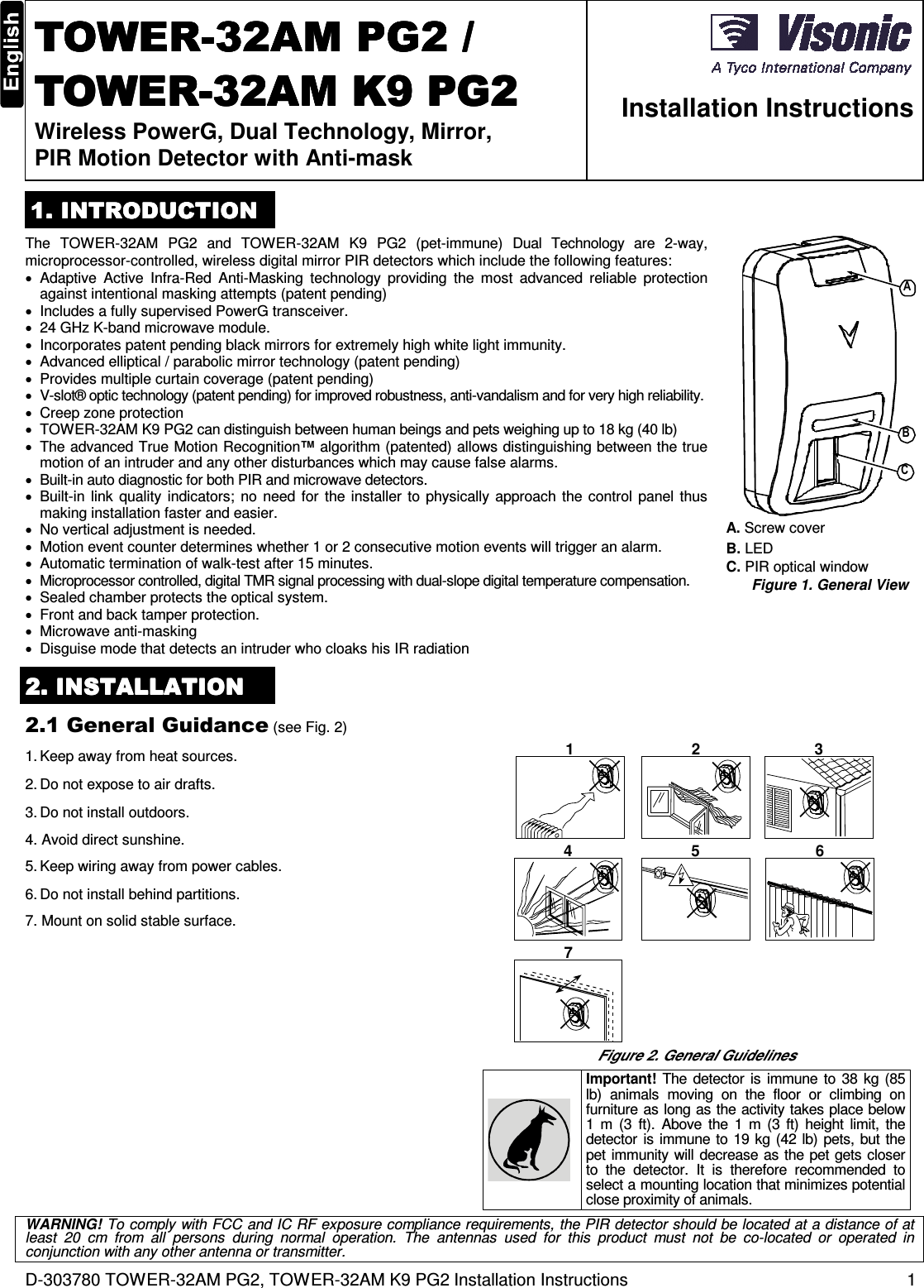
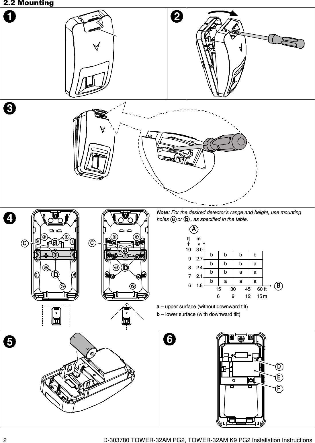
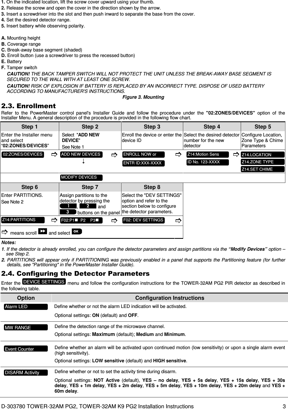
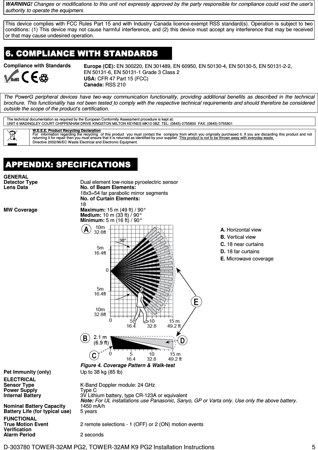
![4 D-303780 TOWER-32AM PG2, TOWER-32AM K9 PG2 Installation Instructions Define the activity and the sensitivity level of the PIR anti-masking. Optional settings: LOW sensitive (default), HIGH sensitive and disabled. Define whether to enable or disable the anti-masking of the microwave sensor. Optional settings: disabled (default), and enabled. Disguise mode is used to detect movement of an intruder who cloaks his IR radiation to avoid detection. Define whether to enable or disable this mode. Optional settings: disabled (default), and enabled. 3333. . . . LOCAL DIAGNOSTICS TESTLOCAL DIAGNOSTICS TESTLOCAL DIAGNOSTICS TESTLOCAL DIAGNOSTICS TEST A. Separate the base from the cover (see Fig. 3). B. Put back the cover to return the tamper switch to its normal (undisturbed) position, and then secure the front cover to the base with the case closure screw. C. The TOWER-32AM PG2 will enter a 2 min. stability period. During this time the red LED blinks. D. Walk-test the coverage area - see Figure 4. Walk across the far end of coverage pattern in both directions; the red LED lights each time your motion is detected followed by 3 LED blinks. The following table indicates the received signal strength indication. LED response Reception Green LED blinks Strong Orange LED blinks Good Red LED blinks Poor No blinks No communication IMPORTANT! Reliable reception must be assured. Therefore, "poor" signal strength is not acceptable. If you receive a "poor" signal from the detector, re-locate it and re-test until a "good" or "strong" signal strength is received. Note: For detailed Diagnostics Test instructions refer to the control panel Installer Guide. 4. EVENT 4. EVENT 4. EVENT 4. EVENT INDICATIONSINDICATIONSINDICATIONSINDICATIONS LED Indications Event Red LED blinks Stabilization (warm-up 120 sec) Red LED ON 0.2 sec. Tamper open / close Red on 2 sec. Intruder alarm Yellow LED on AM detection – diagnostic mode Yellow LED blinks slowly (0.2 sec. ON, 30 sec. OFF) AM detection – Normal mode Yellow and red LED blink simultaneously (0.2 sec. ON [both], 0.2 sec. OFF) Self-test failure – Diagnostic mode Yellow and red LED blink simultaneously slowly (0.2 sec. ON [both], 30 sec. OFF) Self-test failure – Normal mode Green LED blinks PIR detection – Diagnostic mode Green LED on Microwave detection – diagnostic mode 5555. . . . SPECIAL COMMENTSSPECIAL COMMENTSSPECIAL COMMENTSSPECIAL COMMENTS Even the most sophisticated detectors can sometimes be defeated or may fail to warn due to: DC power failure / improper connection, malicious masking of the lens, tampering with the optical system, decreased sensitivity in ambient temperatures close to that of the human body and unexpected failure of a component part. The above list includes the most common reasons for failure to detect intrusion, but is by no means comprehensive. It is therefore recommended that the detector and the entire alarm system be checked weekly, to ensure proper performance. An alarm system should not be regarded as a substitute for insurance. Home and property owners or renters should be prudent enough to continue insuring their lives and property, even though they are protected by an alarm system. This device has been tested and found to comply with the limits for a Class B digital device, pursuant to Part 15 of the FCC Rules. These limits are designed to provide reasonable protection against harmful interference in residential installations. This equipment generates uses and can radiate radio frequency energy and, if not installed and used in accordance with the instructions, may cause harmful interference to radio and television reception. However, there is no guarantee that interference will not occur in a particular installation. If this device does cause such interference, which can be verified by turning the device off and on, the user is encouraged to eliminate the interference by one or more of the following measures: – Re-orient or re-locate the receiving antenna. – Increase the distance between the device and the receiver. – Connect the device to an outlet on a circuit different from the one that supplies power to the receiver. – Consult the dealer or an experienced radio/TV technician. MW ANTI MASKING ANTI MASKING DISGUISE MODE](https://usermanual.wiki/Visonic/TOWER32PG2/User-Guide-1900110-Page-4.png)