Visonic ZBT PCA ZBT (2.4 GHz) RF ZIGBEE MODULE User Manual
Visonic Ltd. PCA ZBT (2.4 GHz) RF ZIGBEE MODULE Users Manual
Visonic >
Users Manual
D-303360 CLIP SMA Installer's Guide 1
CLIP SMA
Wireless Curtain-Type Infrared Detector
Installation Instructions
1. INTRODUCTION
The CLIP SMA is the smallest and most elegant wireless curtain-
pattern PIR detector for indoor use and designed for easy
installation. Its function is based on new and sophisticated,
patented FM data acquisition and digital signal processing.
Modern technology is used to include 3 different detectors in a
single case, each programmable for optimized performance at
the specific mounting location. This results in better catch
performance and virtually no false alarms.
The superiority in performance of this detector is achieved by
applying an improved version of the patented True Motion
Recognition™ (TMR) algorithm. This advanced motion analysis
method allows the CLIP SMA to distinguish between the true
motion of the human body and any other disturbances that cause
false alarms.
After detection, the detector disarms itself to save battery power.
It rearms (reverts to the ready state) if there is no subsequent
detection throughout the following 2-minute period.
The CLIP SMA includes the following features:
Very low current consumption
Microprocessor-controlled temperature compensation
Sealed chamber protects the optical system
Front cover tamper switch
White light protection
Elegantly styled, sturdy case
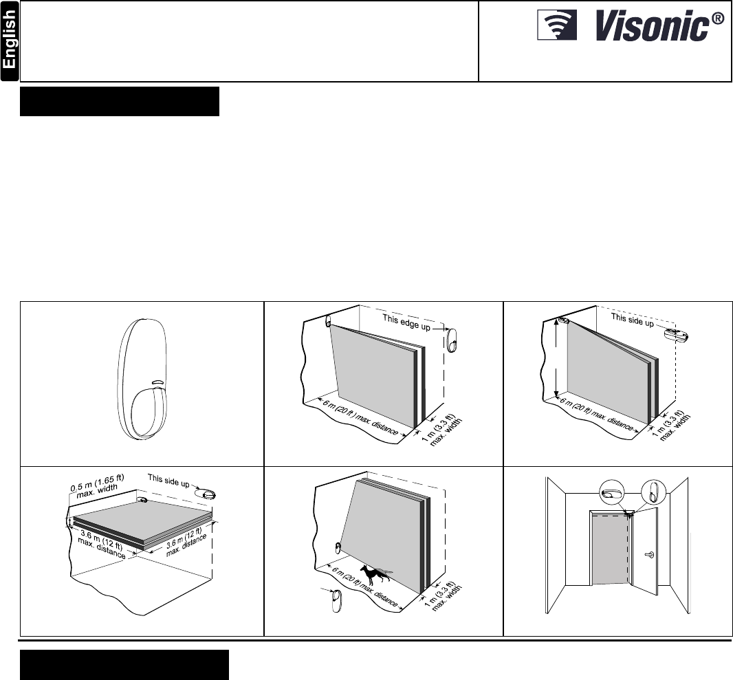
Detailed coverage patterns and mounting alternatives are
illustrated in Figures 2 through 6.
Figure 1. CLIP SMA General View
Figure 2. Wall-Mount Curtain
2.4m
Figure 3. Ceiling-Mount Curtain
Figure 4. Overhead Curtain
This
side
up
Figure 5. Curtain / Pet Alley
OPTION A OPTION B
DETECTION
CURTAIN
Figure 6. CLIP SMA on Internal Doorframe
2. SPECIFICATIONS
OPTICAL
Detector Type: Dual-element low noise pyroelectric sensor.
Number of Curtain Beams: 2
Mounting Positions: See Figures 2 through 6.
Range Settings: Long (6 m/18 ft), Medium (4 m/12 ft) and Short (1.2 -
2m/6 ft) (Jumper-selected).
ELECTRICAL
Internal Battery: 3V Lithium battery, type CR123A. For UL installations,
use Panasonic, GP or Sanyo only.
Nominal Battery Capacity: 1450 mAh.
Battery Life: 3 years (for typical use).
Note: Inability to connect with wireless network, or wireless link quality no
higher than 20% may significantly reduce the expected battery life.
Battery Power Test: Performed immediately upon battery insertion
and periodically every several hours.
Microprocessor: 8-bit, low power CMOS.
FUNCTIONAL
Visual Indications (red LED):
LED lights for about 3 seconds upon transmission of alarm & tamper
messages and upon motion detection in the walk test mode.
LED flashes during the power-up stabilization period (approx. 2
min), or after restoring the cover (by pressing the tamper switch).
LED does not light upon transmission of supervision messages.
Alarm Period: Approx. 3 seconds.
Rearm Timer: Rearms the detector 2 minutes after the last alarm.
WIRELESS
Frequency: 2.4 Ghz as per IEEE 802.15.4
Tamper Alert: Reported when a tamper event occurs and in any
subsequent message, until the tamper switch is restored.
Supervision Message: Signaling at 24-minute intervals.
MOUNTING
Height: 1.8 - 2.4 m (6 - 8 ft). See Figures 2 – 6.
Installation Options: See Figures 2 – 6.
ENVIRONMENTAL
Operating Temperature: -10°C to 50°C (14°F to 122°F).
Storage Temperature: -20°C to 60°C (-4°F to 140°F).
RFI Protection: > 20 V/m to 1000 MHz.
Compliance with standards:
USA: CFR 47 part 15, Canada: RSS 210.
ANSI/UL 639, ULC – S306
PHYSICAL
Dimensions (H x W x D): 105 x 35 x 30 mm (4-1/8 x 1-3/8 x
1-3/16 in.).
Weight (with battery): 60 g (2.1 oz).
Color: White.
PATENTS U.S. Patent 5,693,943 (other patents pending)
2 D-303360 CLIP SMA Installer's Guide
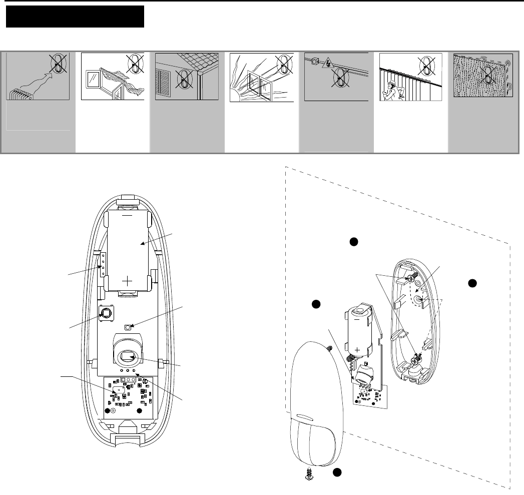
3. INSTALLATION
3.1 General Guidelines
Do not install
near sources of
heating/cooling.
Do not aim at
windows.
Do not install
outdoors.
Do not install
where direct
sunlight can
strike the unit.
Do not install
near high-
voltage electrical
lines.
Do not install
behind any
obstruction.
Do not mount
on unstable
surfaces.
3.2 Regular Mounting
FRONT
TAMPER
SWITCH
SENSOR
RANGE
SELECT
J
UMPE
R
3 VOLT
LITHIUM
BATTERY
BACK
TAMPER
SWITCH
(OPTIONAL)
RF
MODULE
LEDS
Figure 7. Internal View
BREAK-AWAY
SEGMENT
ATTENTION: The back tamper
switch becomes functional
only when the break-away
segment is secured to the
wall with a scre w .
MOUNTING SUR
FACE
INSERT SCREW TO
SECURE COVER
WITH BASE
4
3
POSITION THE
PCB IN ITS
PLACE IN THE
BASE
1
DRILL TWO HOLES
IN THE MOUNTING
SURFACE AND
SECURE BASE
WITH TWO
SCREWS 2
FOR BACK TAMPER
(OPTIONAL), DRIL L
TWO HOLES
AND SECURE
WITH TWO SCREW
Figure 8. Surface Mounting
Notes:
1) After mounting, be sure that no gaps remain in the detector
housing, for example, in the area around the screw holes.
2) Remove the battery using your fingers, and not with a screwdriver.
3.3 Bracket Mounting
Note: When mounting using the bracket, the back tamper is not
functional.
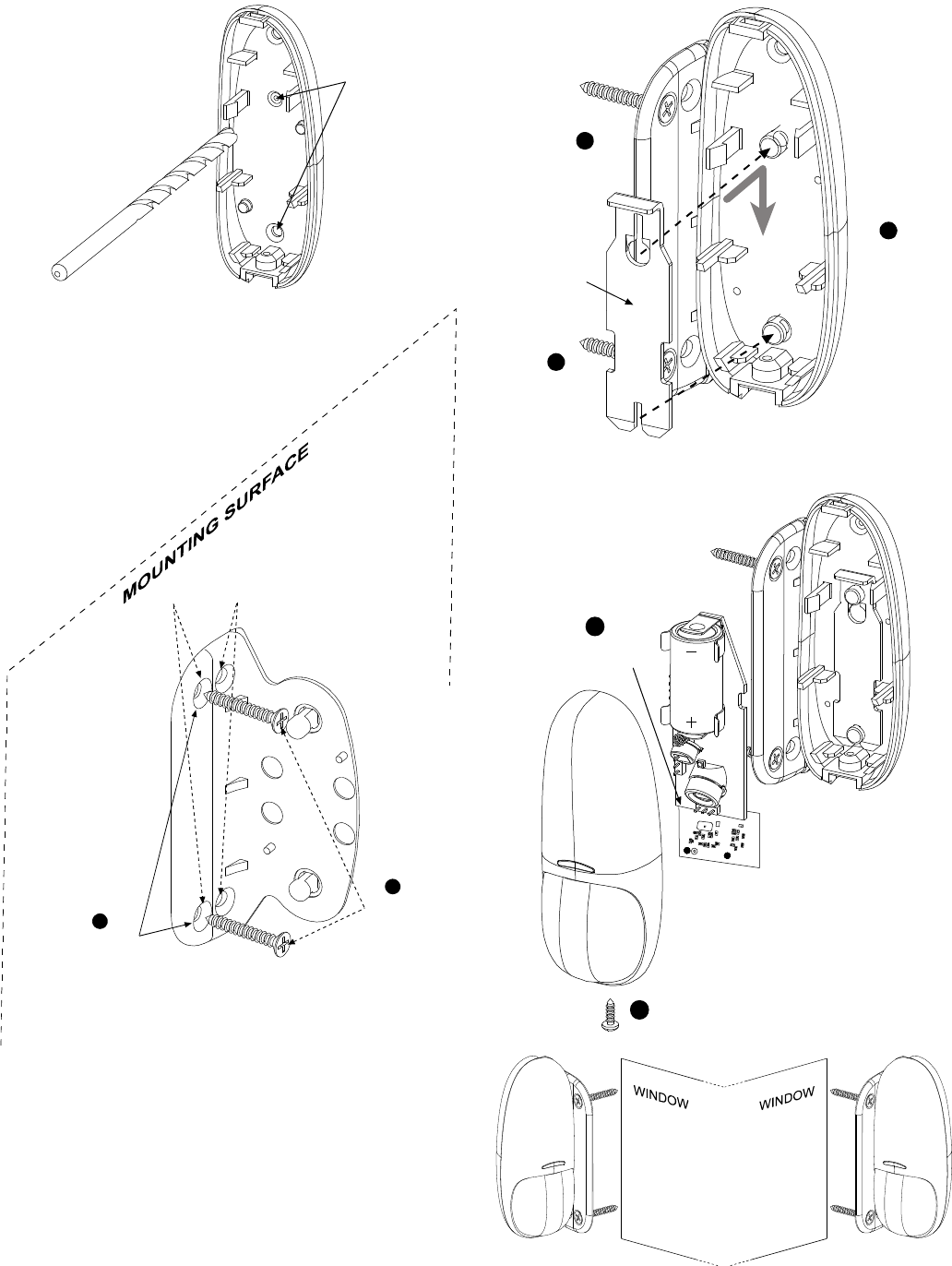
D-303360 CLIP SMA Installer's Guide 3
DRILL TWO
7 mm (1/4“)
HOLES
AT THE
MARKED
SPOTS
Figure 9. Drilling Holes
NOTE: THE BRACKET PROVIDES TWO MOUNTING OPTIONS
FOR OPTIMUM ANGLE COVERAGE .
USE THESE TWO HOLES TO INCREASE
THE COVERAGE RANGE BY 5
USE THESE TWO HOLES TO INCREASE THE
COVERAGE RANGE BY 10
DRILL TWO
HOLES IN THE
MOUNTING
SURFACE
1
SECURE
BRACKET
WITH TWO
SCREWS
2
***
Figure 10. Mounting Bracket to Surface
PLACE THE
LOCKING PLATE
OVER THE TWO
PINS
2
SECURE THE
LOCKING
PLATE BY
PRESSING
DOWNWARD
3
LOCKING
PLATE
PLACE THE
BASE SLOTS
OVER THE
TWO
BRACKET
PINS
1
Figure 11. Securing Locking Plate to Base
POSITIONTHE
PCB CORRECTLY
IN THE BASE
1
INSERT SCREWTO
SECURE COVER
WITH BASE
2
Figure 12. Mounting Cover to Base
Note: The CLIP SMA can be mounted on either side of a window.
Figure 13. Mounting on Both Sides of a Window
4 D-303360 CLIP SMA Installer's Guide
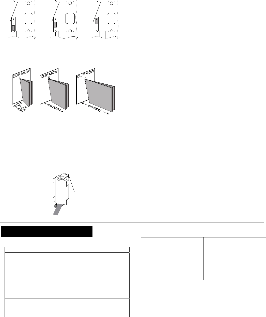
3.4 Setting the Coverage Range
A 4-pin jumper is used to select 3 ranges, according to the type of
installation, for the curtain beams (see Figures 2-6 and 15).
Short range -
approx.
2 m (6 ft)
Medium range -
approx.
4 m (12 ft)
Long range -
approx.
6 m (18 ft)
Figure 14. Range Jumper Settings
Short Range Medium Range Long Range
Figure 15. Range Setting Diagram
The purpose of the range setting is to ensure optimal signal
processing and high immunity against false alarms.
Mount the range jumper in the desired position and make sure
that the protected area is within the selected coverage range (see
figure 15). Carry out a walk test (see Para. 3.7) to verify proper
performance.
3.5 Activating the Detector
To activate, pull the strip that protrudes from the battery
compartment.
Figure 16. Activation Strip
3.6 Pairing/Defaulting the Detector
To pair the detector to the control panel, you must set it to pairing
mode.
A. Press and hold down the detector’s tamper switch.
B. Insert the battery into the detector. Wait for the RF
module’s green LED to light.
C. Release the tamper switch and press it again within 4
seconds. When the detector is in pairing mode, the
green LED starts to blink.
D. Complete the pairing procedure on the control panel
(see the pairing instructions in the control panel’s
installation guide).
3.7 Walk Testing
A. Mount the cover and tighten the screw. Wait for the detector
to stabilize (the LED stops flashing approx. two minutes after
the cover is closed).
B. Walk slowly across the far end of the curtain pattern (in
opposite directions). The LED indicator lights for approx. 3
seconds whenever you enter or exit a curtain beam.
Important: Perform walk test at least once a week to assure
proper function of the detector.
Note: After closing the cover the detector enters a 15 minute
walk-test mode. In this mode the LED will flash each time a
detection occurs, regardless of LED jumper settings, and the
detector will transmit on the occurrence of each detection event.
4. TROUBLESHOOTING
If you encounter one of the following problems with the CLIP
SMA, perform the suggested remedy:
Problem Remed
y
Attempt to pair the sensor is
unsuccessful. Make sure that the sensor has
been defaulted and is set to
pairing mode (see section 3.6).
The sensor and the panel do
not communicate. Perform the signal strength
testing procedure described in
the control panel installation
manual. Make sure that the
signal is sufficient. If
necessary, replace the
sensor’s battery.
The sensor sends a Low
Battery indication. To ensure continuous proper
operation, replace the battery
within two weeks of the first
Low Battery indication.
Problem Remed
y
Panel does not arm because of
an unrecognized sensor
malfunction
Consult with your installer or
system provider before you
disable a zone.
Disable the sensor zone (see
the control panel user manual).
Note that disabling a sensor
zone lowers the overall security
level of your system.

D-303360 CLIP SMA Installer's Guide 5
5. SPECIAL COMMENTS
5.1 Product Limitations
Visonic Ltd. wireless systems are very reliable and are tested to
high standards. However, due to their low transmitting power and
limited range (required by FCC and other regulatory authorities),
there are some limitations to be considered:
A. Receivers may be blocked by radio signals on or near their
operating frequencies, regardless of the code selected.
B. A receiver can only respond to one signal at a time.
C. Wireless equipment should be tested regularly to determine
whether there are sources of interference and to protect
against faults.
D. Even the most sophisticated detectors can sometimes be
defeated or may fail to warn due to: DC power failure /
improper connection, malicious masking of the lens,
tampering with the optical system, decreased sensitivity in
ambient temperatures near that of the human body and
unexpected failure of a component part.
The above list includes the most common reasons for failure
to detect intrusion, but is by no means comprehensive. It is
therefore recommended that the detector and the entire alarm
system be checked weekly, to ensure proper performance.
E. An alarm system should not be regarded as a substitute for
insurance. Home and property owners or renters should be
prudent enough to continue insuring their lives and property,
even though they are protected by an alarm system.
5.2 Compliance with Standards
FCC
This device complies with Part 15 of the FCC Rules and RSS-210 of
Industry and Science Canada. Operation is subject to the following two
conditions: (1) This device may not cause harmful interference, and (2) this
device must accept any interference received, including interference that
may cause undesired operation.
This device complies with Industry Canada license-exempt RSS
standard(s). Operation is subject to the following two conditions: (1) this
device may not cause interference, and (2) this device must accept any
interference, including interference that may cause undesired operation of
the device.
Le présent appareil est conforme aux CNR d'Industrie Canada
applicables aux appareils radio exempts de licence. L'exploitation est
autorisée aux deux conditions suivantes : (1) l'appareil ne doit pas
produire de brouillage, et (2) l'utilisateur de l'appareil doit accepter tout
brouillage radioélectrique subi, même si le brouillage est susceptible
d'en compromettre le fonctionnement.
WARNING! Changes or modifications to this unit not expressly
approved by the party responsible for compliance could void
the user's authority to operate the equipment.
The digital circuit of this device has been submitted for testing in
order to comply with the limits for a Class B digital device,
pursuant to Part 15 of the FCC Rules. These limits are designed
to provide reasonable protection against harmful interference in
residential installations. This equipment generates uses and can
radiate radio frequency energy and, if not installed and used in
accordance with the instructions, may cause harmful interference
to radio and television reception. However, there is no guarantee
that interference will not occur in a particular installation. If this
device does cause such interference, which can be verified by
turning the device off and on, the user is encouraged to eliminate
the interference by one or more of the following measures:
– Re-orient or re-locate the receiving antenna.
– Increase the distance between the device and the receiver.
– Connect the device to an outlet on a circuit different from the
one which supplies power to the receiver.
– Consult the dealer or an experienced radio/TV technician.
Visonic Ltd, M/N: E203826
FCC ID: WP3ZBT
IC: 1467C-ZBT
ANSI/UL
Complies with ANSI/UL 639, ULC – S306

6 D-303360 CLIP SMA Installer's Guide
WARRANTY
Visonic Limited (the “Manufacturer") warrants this product only (the "Product") to the original purchaser only
(the “Purchaser”) against defective workmanship and materials under normal use of the Product for a
period of twelve (12) months from the date of shipment by the Manufacturer.
This Warranty is absolutely conditional upon the Product having been properly installed, maintained and
operated under conditions of normal use in accordance with the Manufacturers recommended installation
and operation instructions. Products which have become defective for any other reason, according to the
Manufacturers discretion, such as improper installation, failure to follow recommended installation and
operational instructions, neglect, willful damage, misuse or vandalism, accidental damage, alteration or
tampering, or repair by anyone other than the manufacturer, are not covered by this Warranty.
The Manufacturer does not represent that this Product may not be compromised and/or circumvented or
that the Product will prevent any death and/or personal injury and/or damage to property resulting from
burglary, robbery, fire or otherwise, or that the Product will in all cases provide adequate warning or
protection. The Product, properly installed and maintained, only reduces the risk of such events without
warning and it is not a guarantee or insurance that such events will not occur.
THIS WARRANTY IS EXCLUSIVE AND EXPRESSLY IN LIEU OF ALL OTHER WARRANTIES,
OBLIGATIONS OR LIABILITIES, WHETHER WRITTEN, ORAL, EXPRESS OR IMPLIED, INCLUDING
ANY WARRANTY OF MERCHANTABILITY OR FITNESS FOR A PARTICULAR PURPOSE, OR
OTHERWISE. IN NO CASE SHALL THE MANUFACTURER BE LIABLE TO ANYONE FOR ANY
CONSEQUENTIAL OR INCIDENTAL DAMAGES FOR BREACH OF THIS WARRANTY OR ANY OTHER
WARRANTIES WHATSOEVER, AS AFORESAID.
THE MANUFACTURER SHALL IN NO EVENT BE LIABLE FOR ANY SPECIAL, INDIRECT,
INCIDENTAL, CONSEQUENTIAL OR PUNITIVE DAMAGES OR FOR LOSS, DAMAGE, OR EXPENSE,
INCLUDING LOSS OF USE, PROFITS, REVENUE, OR GOODWILL, DIRECTLY OR INDIRECTLY
ARISING FROM PURCHASER’S USE OR INABILITY TO USE THE PRODUCT, OR FOR LOSS OR
DESTRUCTION OF OTHER PROPERTY OR FROM ANY OTHER CAUSE, EVEN IF MANUFACTURER
HAS BEEN ADVISED OF THE POSSIBILITY OF SUCH DAMAGE.
THE MANUFACTURER SHALL HAVE NO LIABILITY FOR ANY DEATH, PERSONAL AND/OR BODILY
INJURY AND/OR DAMAGE TO PROPERTY OR OTHER LOSS WHETHER DIRECT, INDIRECT,
INCIDENTAL, CONSEQUENTIAL OR OTHERWISE, BASED ON A CLAIM THAT THE PRODUCT
FAILED TO FUNCTION.
However, if the Manufacturer is held liable, whether directly or indirectly, for any loss or damage arising
under this limited warranty, THE MANUFACTURER'S MAXIMUM LIABILITY (IF ANY) SHALL NOT IN
ANY CASE EXCEED THE PURCHASE PRICE OF THE PRODUCT, which shall be fixed as liquidated
damages and not as a penalty, and shall be the complete and exclusive remedy against the Manufacturer.
When accepting the delivery of the Product, the Purchaser agrees to the said conditions of sale and
warranty and he recognizes having been informed of.
Some jurisdictions do not allow the exclusion or limitation of incidental or consequential damages, so these
limitations may not apply under certain circumstances.
The Manufacturer shall be under no liability whatsoever arising out of the corruption and/or malfunctioning
of any telecommunication or electronic equipment or any programs.
The Manufacturers obligations under this Warranty are limited solely to repair and/or replace at the
Manufacturer’s discretion any Product or part thereof that may prove defective. Any repair and/or
replacement shall not extend the original Warranty period. The Manufacturer shall not be responsible for
dismantling and/or reinstallation costs. To exercise this Warranty the Product must be returned to the
Manufacturer freight pre-paid and insured. All freight and insurance costs are the responsibility of the
Purchaser and are not included in this Warranty.
This warranty shall not be modified, varied or extended, and the Manufacturer does not authorize any
person to act on its behalf in the modification, variation or extension of this warranty. This warranty shall
apply to the Product only. All products, accessories or attachments of others used in conjunction with the
Product, including batteries, shall be covered solely by their own warranty, if any. The Manufacturer shall
not be liable for any damage or loss whatsoever, whether directly, indirectly, incidentally, consequentially or
otherwise, caused by the malfunction of the Product due to products, accessories, or attachments of
others, including batteries, used in conjunction with the Products. This Warranty is exclusive to the original
Purchaser and is not assignable.
This Warranty is in addition to and does not affect your legal rights. Any provision in this warranty which is
contrary to the Law in the state or country were the Product is supplied shall not apply.
Warning: The user must follow the Manufacturer’s installation and operational instructions including testing
the Product and its whole system at least once a week and to take all necessary precautions for his/her
safety and the protection of his/her property.
1/08
W.E.E.E. Product Recycling Declaration
For information regarding the recycling of this product you must contact the company from which you orignially purchased it. If you are discarding this product and not
returning it for repair then you must ensure that it is returned as identified by your supplier. This product is not to be thrown away with everyday waste.
Directive 2002/96/EC Waste Electrical and Electronic Equipment.
VISONIC LTD (ISRAEL): P.O.B 22020 TEL-AVIV 61220 ISRAEL. PHONE: (972-3) 645-6789, FAX: (972-3) 645-6788
VISONIC INC. (U.S.A.):
65 WEST DUDLEY TOWN ROAD
, BLOOMFIELD CT. 06002-1376. PHONE: (860) 243-0833, (800) 223-0020 FAX: (860) 242-8094
VISONIC LTD. (UK): FRASER ROAD, PRIORY BUSINESS PARK, BEDFORD MK44 3WH. TEL.: +44(0)845 0755800 FAX: +44(0)845 0755801
PRODUCT SUPPORT: +44(0)845 755802
INTERNET: www.visonic.com
VISONIC LTD. 2011 CLIP SMA D-303360 - (Rev. 3, 10/11).
D-303365 MCT-302 SMA Installation Instructions 1
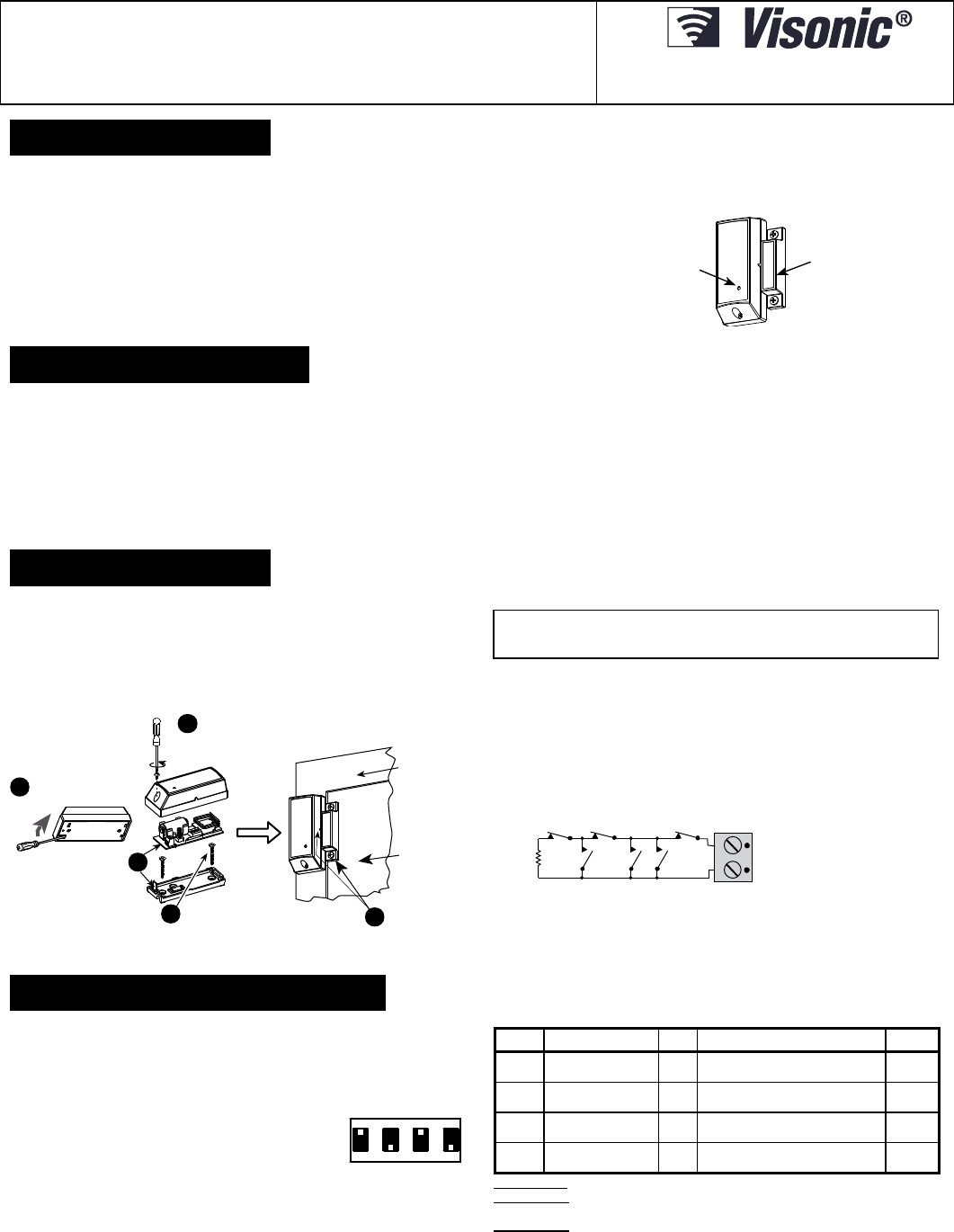
MCT-302 SMA
Magnetic Contact Wireless Sensor
Installation Instructions
1. INTRODUCTION
The MCT-302 SMA is a fully supervised, wireless magnetic contact sensor. The sensor
includes a built-in reed switch (that opens upon removal of a magnet placed near it) and
an auxiliary hard-wired input, programmable as either N.C. or E.O.L., for use with
additional sensors - pushbuttons, detectors, door contacts etc.
An on-board DIP switch allows the installer to disable the magnet- operated reed
switch if only the auxiliary input is needed.
The reed switch and the auxiliary input behave as separate transmitters, although they
trigger the same RF transmitter. Each input has a unique ID.
The MCT-302 SMA tamper switch is activated when the cover is removed.
A periodic supervision message is transmitted automatically. The target receiver is thus
informed, at regular intervals, of the unit’s active participation in the system.
An LED lights whenever alarm or tamper events are reported. The LED does not light
while a supervision message is being transmitted.
Operating power is obtained from an on-board 3V Lithium battery. When the battery
voltage is low, a “low battery” message is sent to the receiver.
MAGNET
TRANSMISSION LED
Fig. 1 - MCT-302 SMA
2. SPECIFICATIONS
Frequency: 2.4 Ghz as per IEEE 802.15.4
Alarm Inputs: 2, one internal and one external, with a separate sensor ID each.
Auxiliary Input Circuit Type: N.C. / E.O.L., selected with DIP switch
E.O.L. Resistor Required: 47 k
Message Repetition: Repetitive transmission (once every 3 minutes) or one-shot, as
selected with on-board DIP switch.
Supervision: Signaling at 24-min. intervals.
Response to Tamper Event: Tamper report every 3 minutes (until the tamper switch
is restored).
Power Source: 3 V Lithium CR-2 type battery, Panasonic, Sanyo or GP only.
Battery Life Expectancy: 3 years (for typical use)
Note: Inability to connect with wireless network, or wireless link quality no higher than
20% may significantly reduce the expected battery life.
Battery Supervision: Automatic transmission of battery condition data as part of any
status report.
Operating Temperature: 0C to 49C (32F to 120F).
Dimensions: 81 x 32 x 25 mm (3-3/16 x 1-1/4 x 1 in.)
Weight: 53g (1.9 oz)
Standards: USA: CFR 47 part 15, Canada: RSS 210.
ANSI/UL 639, ULC – S306
.
3. INSTALLATION
3.1 Mounting (Fig. 2)
It is highly recommended to attach the sensor to the top of the door/window on the fixed
frame and the magnet to the movable part (door or window). Make sure that the magnet is
located not more than 6 mm (0.25 in.) from the sensor’s marked side.
Note: Once the cover is removed, a tamper message is transmitted to the receiver.
Subsequent removal of the battery prevents transmission of "TAMPER RESTORE",
leaving the receiver in permanent alert. To avoid this, during the enrolling process,
press the tamper switch while you remove the battery.
BASE WITH
P.C . BOA RD
2
SEPARATE BASE
FROM COVER
MARK & DRILL 2 HOLES IN MOUNTING SURFACE.
FASTEN BASE WITH 2 COUNTERSUNK SCREWS.
4
3
FLEX CATCH AND
REMOVE BOARD
FIXED FRAME
MOVING PART
MOUNT THE MAGNET NEAR ITS
LOCATION MARK WITH 2 SCREWS.
5
1
REMOVE SCREW
Figure 2 – Mounting the Sensor
3.2 Auxiliary Input Wiring (Fig. 3)
Remember! If your application does not require the auxiliary input, be sure to set
DIP switch SW2 to OFF and to short the input terminals together with a piece of
jumper wire.
A. Connect the auxiliary sensor contacts across the MCT-302 SMA auxiliary input
terminals.
B. If the auxiliary input of the MCT-302 SMA is defined as a Normally Closed (N.C.)
type (SW2 set to OFF), series connected N.C. sensor contacts must be used
exclusively. An E.O.L. resistor will not be required.
C. For E.O.L. supervision, set SW2 to ON.
Normally Closed (N.C.) as well as Normally Open (N.O.) sensor contacts can be
used, as show in figure 3. A 47k E.O.L. resistor must be wired at the far end of
the zone loop.
Note: For UL installations, the device connected to the initiating circuit must be
located in the same room as the sensor.
47
k
N.O. AND N.C. ALARM CIRCUI T
WITH E.O. L RESIS TOR
Figure 3 - E.O.L Wiring Example
NOTE - An alarm message is transmitted once the loop is opened or short circuited.
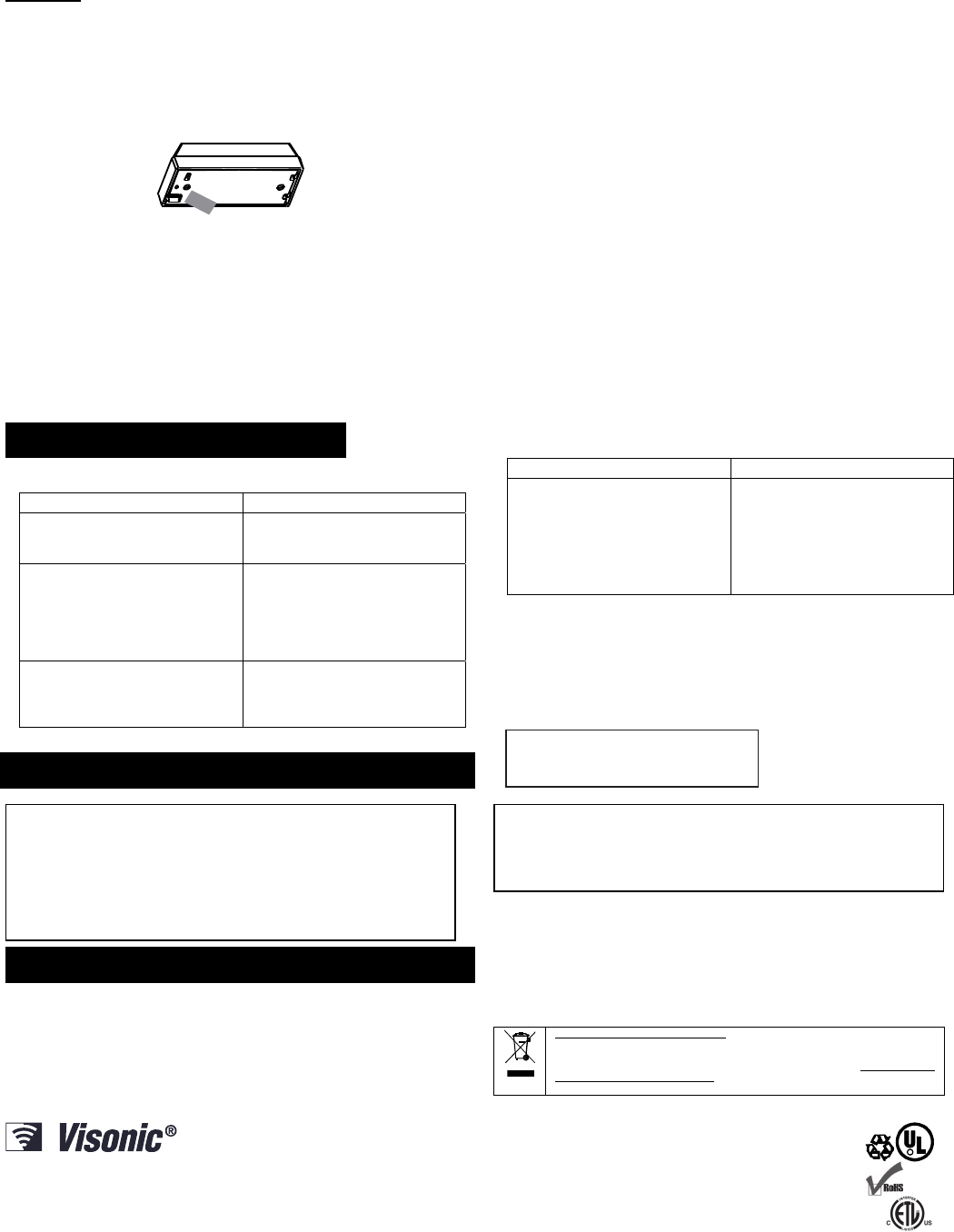
4. PREPARATION FOR USE
4.1 The Function Switches
A. Switch Tasks
The MCT-302 SMA has a 4-position DIP switch function selector. Each switch lever
allows you to select one of two options.
B. Setting the Switches
Set the function switches as desired prior to applying
power. Use a ball point pen or another pointed object to
shift the switch levers. The ON position is indicated by
the arrow on the switch body.
ON
1234
Function Selector
Table 1. Getting acquainted with the function selector
Sw- Function Pos. Selected Option Default
SW1 Reed switch input
enable/disable
ON
OFF
Reed switch input is enabled
Reed switch input is disabled
ON
SW2 Aux. input type
selector
ON
OFF
Aux. input is E.O.L. (47 k
)
Aux. input is N.C.
OFF
SW3 Restore reports
enable/disable
ON
OFF
Restore events reported
Restore events not reported
ON
SW4 Transmit mode
selector
ON
OFF
Alarms reported every 3 min.
Alarms reported only once
OFF
SWITCH SW1: Determines whether the reed switch input will be active or inactive.
SWITCH SW2: Determines whether the auxiliary input will behave as an end-of-line
(E.O.L.) input or as a normally closed (N.C.) input.
SWITCH SW3: Determines whether the sensor will report a restore event when an
input restores from an alarm condition.
2 D-303365 MCT-302 SMA Installation Instructions
Note: Selecting the ON position enables you to find out whether the door or window
under surveillance are open or closed.
Note: For UL installations, SW3 must be set to On position.
SWITCH SW4: In non-supervised systems, it is sometimes required to report an alarm
repeatedly at short intervals, until the disturbed input reverts to its normal
(undisturbed) state. SW4 is used to select between repetitive and one-shot
transmission.
Note: Transmissions initiated by “tamper” events will be repeated once every 3
minutes, regardless of SW4 setting.
When done, install the battery as directed in Para. 4.4.
4.2 Activating the Sensor
To activate, pull the strip that protrudes from the back of the sensor.
Fig. 4 – Activation Strip
4.3 Pairing/Defaulting the Sensor
To pair the sensor to the control panel, you must set it to pairing mode.
1. Press and hold down the sensor’s tamper switch.
2. Insert the battery into the sensor. Wait for the RF module’s green LED to light.
3. Release the tamper switch and press it again within 4 seconds. When the sensor
is in pairing mode, the green LED starts to blink.
4. Complete the pairing procedure on the control panel (see the pairing instructions
in the control panel’s installation guide).
4.4 Testing the Unit
Before testing, set DIP switches SW1 through SW4 as required for the particular
application (Para. 4.1).
A. Insert the battery between the battery clips, at the correct polarity. For proper
operation, only Lithium battery (Panasonic, Sanyo, or GP type CR2) should be
used.
Caution: Risk of explosion if battery is replaced by an incorrect type. Dispose used
battery according to manufacturer's instructions.
B. Press the tamper switch once and release it.
Note: Since the cover is removed and power is applied, a tamper situation exists.
Verify that the MCT-302 SMA transmits (the LED lights briefly) once every 3
minutes.
C. When you are satisfied that tamper signals are transmitted properly, put the cover
on to return the tamper switch to its normal (undisturbed) position. Wait slightly
over 3 minutes to verify that tamper transmissions cease. If operation is normal,
secure the front cover to the base with the case closure screw.
D. Momentarily open the door or window and verify that the sensor LED lights,
indicating that transmission is in progress.
If SW4 is ON, wait 3 minutes to verify that the transmission is repeated at 3-
minute intervals.
E. Close the door or window, thus restoring it to the undisturbed state and watch the
LED. If SW3 is set to ON, a “restore” transmission will now take place.
F. If the auxiliary input is used, momentarily activate the detector connected to it and
check for a response similar to that described in D above. Then restore the input
loop to its undisturbed state. The response should be as in E above.
Note Regarding Tamper Message Transmission:
- If the reed switch input is enabled (SW1 is ON), the tamper message will be sent
with the reed switch’s ID.
- If the reed switch input is disabled (SW1 is OFF), the tamper message will be
sent with the auxiliary input’s ID.
5. TROUBLESHOOTING
If you encounter one of the following problems with the MCT-302 SMA, perform
the suggested remedy:
Problem Remedy
Attempt to pair the sensor is
unsuccessful.
Make sure that the sensor has been
defaulted and is set to pairing mode
(see para 4.3).
The sensor and the panel do not
communicate.
Perform the signal strength testing
procedure described in the control
panel installation manual. Make sure
that the signal is sufficient. If
necessary, replace the sensor’s
battery.
The sensor sends a Low Battery
indication.
To ensure continuous proper
operation, replace the battery within
two weeks of the first Low Battery
indication.
Problem Remedy
Panel does not arm because of an
unrecognized sensor malfunction
Consult with your installer or
system provider before you disable
a zone.
Disable the sensor zone (see the
control panel user manual). Note that
disabling a sensor zone lowers the
overall security level of your system.
6. COMPLIANCE WITH STANDARDS
FCC
This device complies with Part 15 of the FCC Rules and RSS-210 of Industry and
Science Canada. Operation is subject to the following two conditions: (1) This device may
not cause harmful interference, and (2) this device must accept any interference received,
including interference that may cause undesired operation.
This device complies with Industry Canada license-exempt RSS standard(s). Operation is
subject to the following two conditions: (1) this device may not cause interference, and (2)
this device must accept any interference, including interference that may cause undesired
operation of the device.
Le présent appareil est conforme aux CNR d'Industrie Canada applicables aux
appareils radio exempts de licence. L'exploitation est autorisée aux deux conditions
suivantes : (1) l'appareil ne doit pas produire de brouillage, et (2) l'utilisateur de
l'appareil doit accepter tout brouillage radioélectrique subi, même si le brouillage est
susceptible d'en compromettre le fonctionnement.
ANSI/UL
Complies with ANSI/UL 639, ULC – S306
7. MISCELLANEOUS COMMENTS
Visonic Ltd. wireless systems are very reliable and are tested to high standards.
However, due to low transmitting power and limited range (required by FCC and other
regulatory authorities), there are some limitations to be considered:
A. Receivers may be blocked by radio signals occurring on or near their operating
frequencies, regardless of the digital code used.
B. A receiver responds only to one transmitted signal at a time.
C. Wireless devices should be tested regularly to determine whether there are
sources of interference and to protect against faults.
The user is cautioned that changes or modifications to the unit, not expressly
approved by Visonic Ltd., could void the user’s FCC or other authority to
operate the equipment.
W.E.E.E. Product Recycling Declaration
For information regarding the recycling of this product you must contact the company from
which you orignially purchased it. If you are discarding this product and not returning it for
repair then you must ensure that it is returned as identified by your supplier. This product is not
to be thrown away with everyday waste.
European Directive 2002/96/EC Waste Electrical and Electronic Equipment.
VISONIC LTD. (ISRAEL): P.O.B 22020 TEL-AVIV 61220 ISRAEL. PHONE: (972-3) 645-6789, FAX: (972-3) 645-6788
VISONIC INC. (U.S.A.): 65 WEST DUDLEY TOWN ROAD, BLOOMFIELD CT. 06002-1376. PHONE: (860) 243-0833, (800) 223-0020. FAX: (860) 242-8094
VISONIC LTD. (UK): UNIT 6 MADINGLEY COURT CHIPPENHAM DRIVE KINGSTON MILTON KEYNES MK10 0BZ. TEL.: +44(0)845 0755800 FAX: +44(0)845 0755801
PRODUCT SUPPORT: +44(0)845 755802
VISONIC GmbH (D-A-CH): KIRCHFELDSTR. 118, D-40215 DÜSSELDORF, TEL.: +49 (0)211 600696-0, FAX: +49 (0)211 600696-19
VISONIC IBERICA: ISLA DE PALMA, 32 NAVE 7, POLÍGONO INDUSTRIAL NORTE, 28700 SAN SEBASTIÁN DE LOS REYES, (MADRID), ESPAÑA. TEL (34) 91659-3120,
FAX (34) 91663-8468. www.visonic-iberica.es
INTERNET: www.visonic.com
VISONIC LTD. 2011 D-303365 MCT-302 SMA
(
Rev 3, 10/11
)
R
Visonic Ltd, M/N: E203826
FCC ID: WP3ZBT
IC: 1467C-ZBT
D-303364 MCT-427 SMA Installation Guide 1
MCT-427 SMA
Supervised Wireless Smoke / Heat Detector
Installation Instructions
1. DESCRIPTION AND APPLICATIONS
MCT-427 SMA (heat and smoke detector) are automatic fire detectors
with integral audible signal for open area protection, designed to
sense heat or smoke (not flame) and fitted with an iControl compliant
wireless transceiver.
MCT-427 SMA provides early warning of developing fire by sounding
an alarm with its built-in alarm horn, and by transmitting a coded
alarm signal to an iControl compliant control panel.
MCT-427 SMA will activate a fire alarm upon either smoke or heat
(temperature rate-of-rise) condition. With two fire sensors (heat and
smoke), the MCT-427 SMA detector may shorten the time to fire
alarm activation.
It must be borne in mind, though that effective prewarning of fire
accidents is only possible if the detector is located, installed and
maintained as described here.
In alarm condition, the buzzer sound can be stopped for 12 minutes by
pressing the TEST/MUTE switch. It will not restore the alarm condition,
but will temporarily silence the buzzer while you correct the condition.
After 12 minutes, the detector restarts the alarm buzzer sound.
Note: The TEST/MUTE switch functions as TEST switch (in normal
operation) or as MUTE switch (in alarm condition).
The tamper switch actuator (Fig. 3a/3b) is pressed against the bracket
when the unit is attached to the bracket. Removal of the unit from the
bracket causes the switch contacts to open, creating a tamper event,
which is reported by the transmitter to the alarm system control panel.
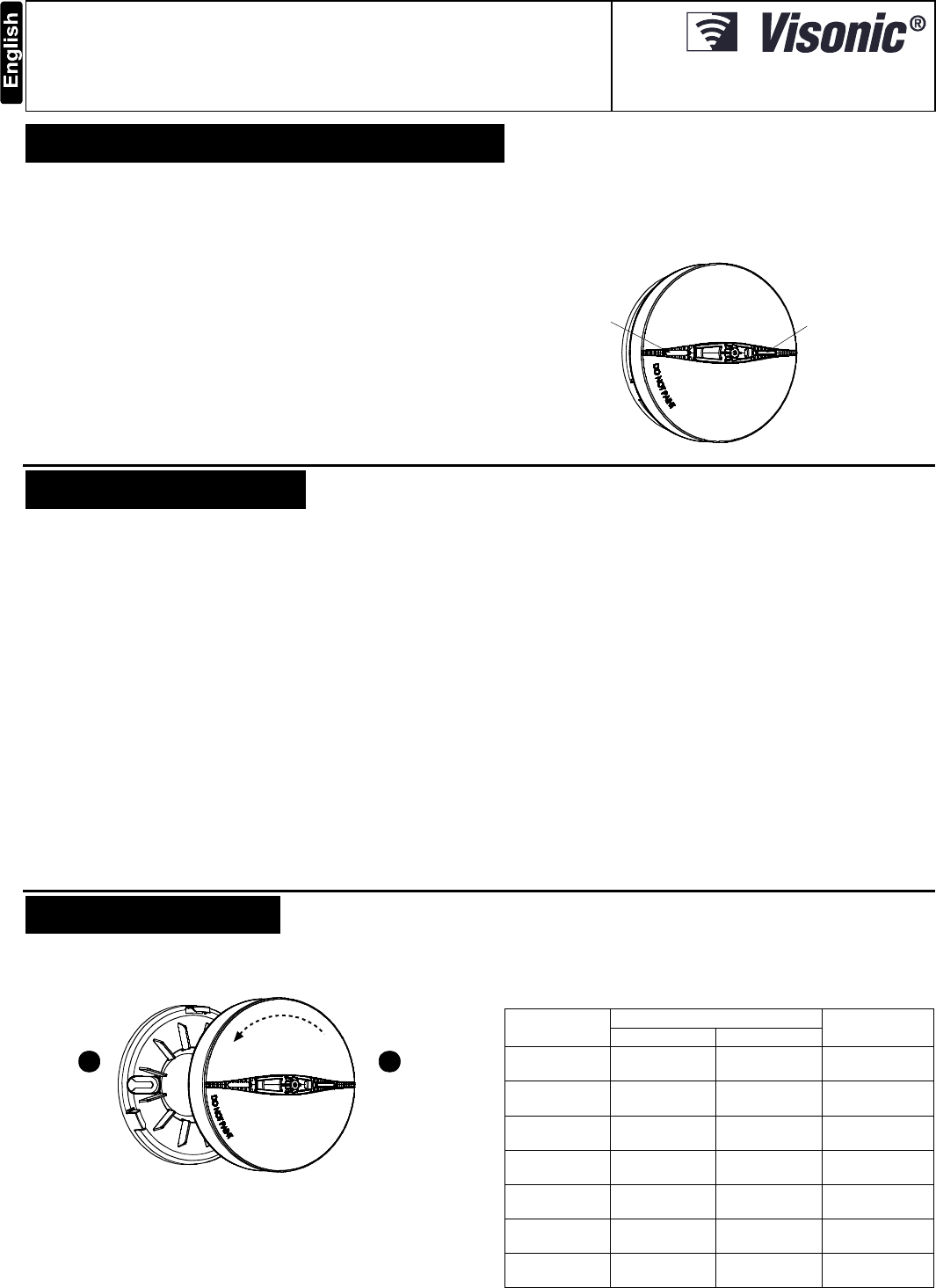
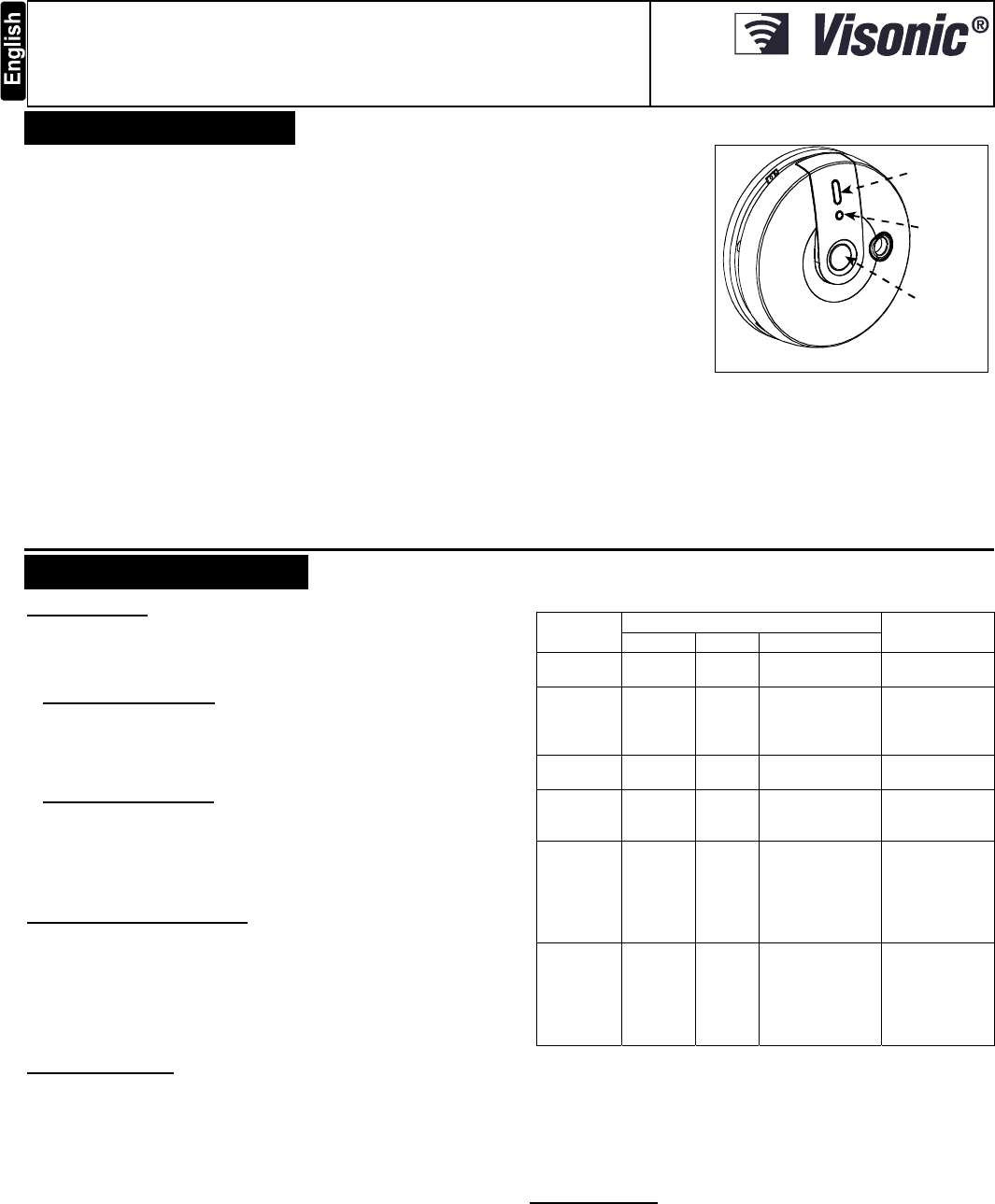
BUZZER
HOLE TEST / MUTE
BUTTON
&
LEDS
Figure 1. General View (MCT-427)
2. SPECIFICATIONS
Alarm Sound Level: 85 dB at 3 m (10 feet)
TRANSMITTER AND CODING
Operating Frequency: 2.4 GHz as per IEEE 802.15.4
Supervision: Automatic signaling at 24-minute intervals.
Tamper Alerts: Tamper event (removal of the unit from its bracket) is
reported once. Tamper restore is reported when the tamper switch is
restored.
Transmission Indicator: Yellow LED lights upon transmission
(visible only when LED function is pre-defined, see par. 3.7).
ALARM REPORT:
Every 20 seconds for the first 3 minutes. Then, every 3 minutes until
30 minutes have elapsed.
Alarm stops reporting after 30 min., or if the detector goes into "alarm
restore".
After 30 minutes, an alarm bit will be sent as part of the supervision
message.
ELECTRICAL DATA
Power Source: 3 Volt CR123A / CR17450 lithium.
Panasonic/GP/Sanyo recommended
Operation Voltage: From 2.7 V to 3 V.
Current Drain: 18 µA standby, 70 mA max. in operation
Smoke Density: 1.44%/ft to 2.74%/ft
Cover Range: 50 – 100 cubic meters (1770 – 3530 cubic ft.)
Battery Supervision: Automatic transmission of battery status data as
part of any transmitted message.
Battery Life Expectancy: Battery life exceeds the minimum life required by
UL 268. Visonic warrantees the life of the battery for 5 years for typical use.
Note: Inability to connect with wireless network, or wireless link
quality no higher than 20% may significantly reduce the expected
battery life.
Audible and Visual Low Battery Warning: Built-in horn beeps every
30 seconds simultaneously with red LED flashing (for up to 30 days
when the battery voltage drops).
Audible and Visual Degraded Chamber Sensitivity Warning: Built-
in horn beeps every 30 seconds in the middle of red LED flashing
intervals – indicates that the detector must be replaced.
Clean Warning Transmission: A clean (maintenance) signal is
transmitted when the detector's chamber becomes stained, causing the
detector to operate at high sensitivity.
PHYSICAL DATA
Operating Temperature: -10C to 50C (14F to 122F).
Relative Humidity: 10% to 85%
Dimensions: 120 mm (4.7") x 63 mm (2.5")
Weight (including battery): 165 g (5.8 oz)
Compliance with Standards:
USA: CFR 47 part 15, Canada: RSS 210.
ANSI/UL 639, ULC – S306
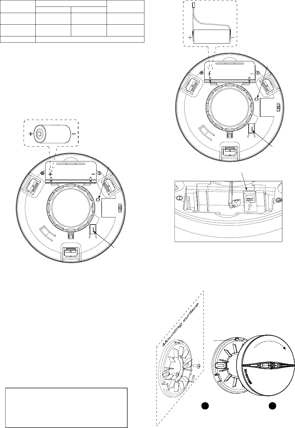
3. INSTALLATION
3.1 Disassembly
Separate the unit from its mounting bracket as shown in Figure 2.
BRACKET DETECTOR
1
Hold the
bracket with
one hand
2
Rotate the
detector
anticlockwise
and pull it from
the bracket
Figure 2. Separating the Detector from Its Bracket
3.2 Audible and Visual Indications
The dual color LED and buzzer are used to signal various alarm and
trouble messages as shown in Table 1 below:
Table 1. Visual and Audible Indications
Condition Visual Indication (LEDs) Audio
Indication
Red Yellow
Smoke alarm Flash every
500ms - 3 long beeps every
4 sec.
Heat alarm(***) Flash every
500ms - Long beep every
2 sec.
Tamper
alarm(*) - - Long beep every
2 sec.
Standby Flash every 30
sec. - -
Low battery Flash every 30
sec. - Short beep every
30 sec.
Smoke sensor
trouble Flash every 60
sec. 3 Flashes every
60 sec. Short beep every
60 sec.
Low sensitivity
alarm Flash every 30
sec.(**) - Short beep every
30 sec.
2 D-303364 MCT-427 SMA Installation Guide
Condition Visual Indication (LEDs) Audio
Indication
Red Yellow
Heat sensor
trouble Flash every 60
sec. 5 Flashes every
60 sec. Short beep every
60 sec.
Need to clean 2 flashes every
30 sec. - 2 short beeps
every 30 sec.
Test See par. 3.6
* The tamper alarm will mute for 3 minutes at first power on, and
will revert to normal mode when the tamper switch condition is
changed.
** Delay of 15 sec. between buzzer beep and LED operation
3.3 Battery Connection and Initial Test
Caution! Risk of explosion if battery is replaced by an incorrect type.
Dispose of used batteries according to the manufacturer's instructions.
Attention: The detector battery cover is fitted with a red button that
prevents the detector from locking onto bracket if there is no battery
inside.
The smoke detector is supplied with a 3V CR123A / CR17450 battery.
Battery connection for both types of batteries is illustrated in Figure 3a
and 3b below.
Battery cover
Open battery cover and
connect the battery to its
terminals (without
insulator). Verify proper
polarity.
3 volts CR123A
Tamper
switch
Transmission
LED ON/OFF
button
Figure 3a. Battery Connection for CR123A
Battery cover
Open battery cover and connect the battery to its terminals.
3 volts CR17450
Tamper
switch
Transmission
LED ON/OFF
button
Figure 3b. Battery Connection for CR17450
Note: When the battery first makes contact, the alarm horn may
sound for one second. This indicates that the battery is connected
properly.
Close the cover, then press the test button (see fig. 1) for about 5
seconds, (for further details see par. 3.6)
.
3.4 Pairing/Defaulting the Detector
Note: It is much easier to carry out this operation while holding the
MCT-427 in your hand, close to the control panel.
To pair the detector to the control panel, you must set it to pairing
mode.
A. Press and hold down the detector’s tamper switch.
B. Insert the battery into the detector. Wait for the RF
module’s green LED to light.
C. Release the tamper switch within 4 seconds and press it
again. When the detector is in pairing mode, the green
LED starts to blink.
D. Complete the pairing procedure on the control panel (see
the pairing instructions in the control panel’s installation
guide).
3.5 Mounting
1
Mark and drill 2 holes in
the mounting surface.
Fasten the bracket to the
mounting surface with 2 screws.
2
Align bracket tabs with the
detector slots and rotate the detector
as shown. Pull the detector outward to
verify that it is securely attached.
BRACKET DETECTOR
tab
(1 of 3)
Figure 4. Mounting the Detector
Notes
1. A battery must be inserted into the detector
before the detector can be mounted onto the
bracket.
2. Unauthorized removal of the unit from the bracket
will initiate a tamper alert!
D-303364 MCT-427 SMA Installation Guide 3
3.6 Test
Enter the test mode by pressing the test button. In this mode, the
detector will test smoke, heat and battery functions. If all functions are
good, the red LED lights 0.5s, off 0.5s, the yellow LED lights 0.5s, off
0.5s followed by a loud 3-beep alarm and the red LED flashes
simultaneously. Otherwise, the detector produces the warning signals
as detailed in Table 1.
3.7 LED Transmission Procedure
The yellow LED can be set to ON or OFF by pressing the
Transmission LED (yellow) ON/OFF button (see Figure 3a), as
indicated in Table 2 below.
Table 2. Interpreting the Transmission ON/OFF Button
Transmission LED ON/OFF
button (yellow) press
LED (yellow) Status during
transmission
Press and release, flashes once ON
Press and release, flashes twice OFF
4. SMOKE DETECTOR INSTALLATION OVERVIEW
4.1 Where to Install Smoke Detectors
Smoke detectors should be installed in accordance with the NFPA
Standard 74 (National Fire Protection Association, Batterymarch
Park, Quincy, MA 02169). For complete coverage in residential units,
smoke detectors should be installed in all rooms, halls, storage
areas, basements and attics in each family living unit. Minimum
coverage is one detector on each floor and one in each sleeping area
and attics in each family living unit. For maximum protection, a
smoke detector should be located outside primary sleeping areas or
on each level of your home. Here are a few useful tips for you:
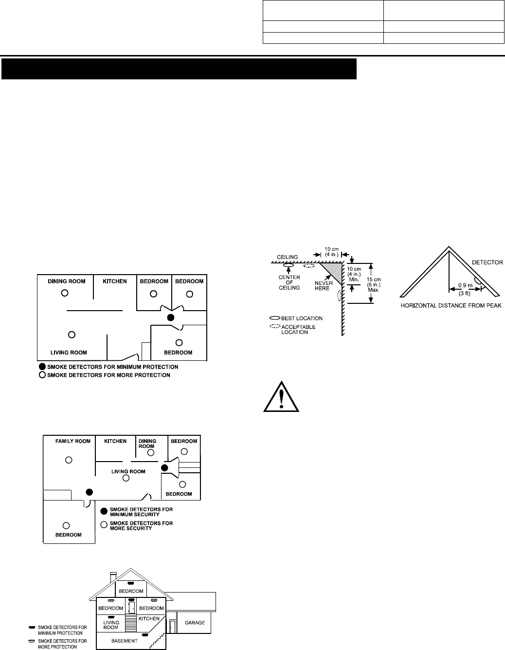
Install a smoke detector in the hallway outside every separate
bedroom area, as in Figure 5. Two detectors are required in homes
with two bedroom areas, as in Figure 6.
Install a smoke detector on every floor of a multi-floor home or
apartment, as shown in Figure 7.
Install a minimum of two detectors in any household.
Install a smoke detector inside every bedroom.
Install smoke detectors at both ends of a bedroom hallway if the
hallway is more than 12 meters (40 feet) long.
Figure 5. Locations for Placing Smoke Detectors in a Single
Residence with only One Sleeping Area
Install a smoke detector inside every room where one sleeps with
the door partly or completely closed, since smoke could be blocked
by the closed door and a hallway alarm may not wake up the
sleeper if the door is closed.
Figure 6. Locations for Placing Smoke Detectors in Single-Floor
Residence with More than One Sleeping Area.
Figure 7. Placing Smoke Detectors in a Multi-Floor Residence
Install basement detectors at the bottom of the basement stairwell.
Install second-floor detectors at the top of the first-to-second floor
stairwell.
Be sure no door or other obstruction blocks the path of smoke to
the detector.
Install additional detectors in your living room, dining room, family
room, attic, utility and storage rooms.
Install smoke detectors as close to the center of the ceiling as
possible. If this is not practical, put the detector on the ceiling, at
least 10 cm (4 inches) away from any wall or corner, as shown in
Figure 8.
If ceiling mounting is not possible and wall mounting is permitted by
your local and state codes, locate the detectors between 10 - 15
cm (4 - 6 inches) from the ceiling, also see Figure 8.
If some of your rooms have sloped, peaked, or gabled ceilings, try
to mount detectors 0.9 meter (3 feet) measured horizontally from
the highest point of the ceiling as shown in Figure 9.
Figure 8. Recommended Best
and Acceptable Locations to
Mount Smoke Detectors
Figure 9. Recommended
Location to Mount Smoke
Detectors in Rooms with
Sloped, Gabled or Peaked
Ceiling
CAUTION (As required by the California State Fire
Marshall)
"Early warning fire detection is best achieved by the
installation of fire detection equipment in all rooms and
areas of the household as follows:
(1) A smoke detector installed in each separate sleeping area (in the
vicinity, but outside the bedrooms), and (2) Heat or smoke detectors
in the living rooms, dining rooms, bedrooms, kitchens, hallways,
attics, furnace rooms, closets, utility and storage rooms, basements
and attached garages."
4.2 Where Not to Install Smoke Detectors
False alarms occur when smoke detectors are installed where they
will not work properly. To avoid false alarms, do not install smoke
detectors in the following situations:
Combustion particles are by-products of something burning. Do not
install smoke detectors in or near areas where combustion particles
are present, such as kitchens with few windows or poor ventilation,
garages where there may be vehicle exhaust, near furnaces, hot
water heaters and space heaters.
Do not install smoke detectors less than 6 meters (20 feet) away
from places where combustion particles are normally present, like
kitchens. If a 20-foot distance is not possible, try to install the
detector as far away from the combustion particles as possible,
preferably on the wall. To prevent false alarms, provide good
ventilation in such places.
IMPORTANT: Never try to avoid false alarms by disabling the
detector.
4 D-303364 MCT-427 SMA Installation Guide
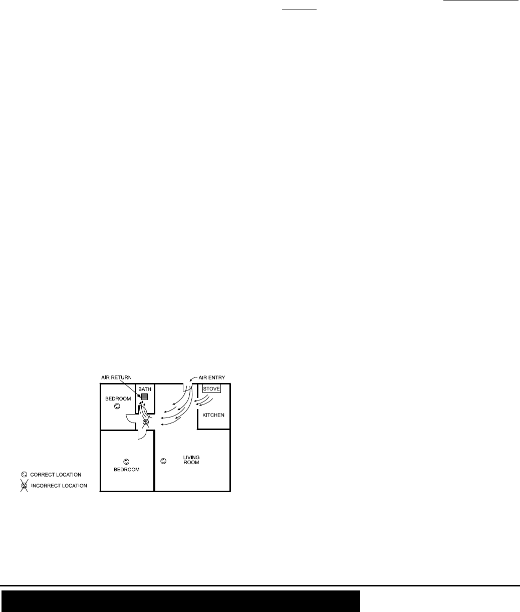
Do not mount smoke detectors in the path of fresh air intake. The
flow of fresh air in and out can drive smoke away from the smoke
detector; thus reducing its efficiency. Figure 10 indicates the correct
and incorrect locations concerning this problem.
Near pain thinner fumes.
In close proximity to an automobile exhaust pipe; this will damage
the detector.
In damp or very humid areas or near bathrooms with showers.
Moisture in humid air can enter the sensing chamber, then turns
into droplets upon cooling, which can cause false alarms. Install
smoke detectors at least 3 meters (10 feet) away from bathrooms.
In very cold or very hot areas, including unheated buildings or
outdoor rooms. If the temperature goes above or below the
operating range of smoke detector, it will not work properly. Verify
that the temperature range of the detector falls within the Operating
Temperature, (see chapter 2. Specifications).
In very dusty or dirty areas, dirt and dust can build up on the
detector's sensing chamber, to make it overly sensitive.
Additionally, dust or dirt can block openings to the sensing
chamber and keep the detector from sensing smoke.
Near fresh air vents or very drafty areas like air conditioners,
heaters or fans. Fresh air vents and drafts can drive smoke away
from smoke detectors.
Dead air spaces are often at the top of a peaked roof, or in the
corners between ceilings and walls. Dead air may prevent smoke
from reaching a detector. See Figures 8 and 9 for recommended
mounting locations.
In insect-infested areas. If insects enter a detector's sensing
chamber, they may cause a false alarm. Where bugs are a
problem, get rid of them before putting up a detector.
Near fluorescent lights, electrical "noise" from fluorescent lights
may cause false alarms. Install smoke detectors at least 1.5 meters
(5 feet) from such lights.
Smoke detection depends on the smoke density present in a
room. Smoke density is greater in small rooms, for the same
amount of smoke, than in large rooms.
In small rooms less than 25 cubic meters (883 cubic ft.) in size,
a small amount of smoke may activate a smoke alert. For
example, smoking or bathroom steam may activate a smoke
alert.
Figure 10. Recommended Smoke Detector Locations to Avoid Air
Streams with Combustion Particles
WARNING: Never remove batteries to stop a false alarm. Open a
window or fan the air around the detector to get rid of the smoke. The
alarm will turn itself off when the smoke is gone. If false alarms persist,
attempt to clean the detector as described in this manual.
WARNING: Do not stand close to the detector when the alarm is
sounding. The alarm is loud in order to wake you in an emergency.
Too much exposure to the horn at close range may be harmful to your
hearing.
4.3 Smoke Detector Limitations
A. This smoke detector is designed for use in a single residential unit
or offices, which means that it should be used inside a single
family home or apartment or office.
B. Please refer to NFPA 101, the Life Safety Code, NFPA72 for smoke
detector requirements for fire protection in buildings not defined as
"households".
C. The smoke detector will not sense a fire if the smoke does not
reach the sensor. In order for a smoke detector to sense smoke, it
must be installed in the immediate vicinity of the fire.
In addition, smoke from fires in chimneys, in walls, on roofs, in remote
parts of the building, or on another level from where the smoke detector
is located, may not reach the smoke detector quickly enough for
occupants to escape unharmed. For this reason, installer shall install
smoke detectors on every level, in every sleeping area and in every
bedroom of the household.
D. Smoke detector may not be heard. The alarm horn in this smoke
detector meets or exceeds current Underwriter’s Laboratories
standards. However, if the smoke detector is not located in the same
room as the occupant or if it is blocked by a closed door or normal
noise, the alarm horn may not be heard. In addition, sound sleepers,
or persons who are under the influence of drugs or alcohol may not
hear the alarm or be able to react to it. Therefore, locate this
smoke detector, which has a sounder rated at 85 dB at 10 feet,
on every level, in every sleeping area and in every bedroom of
the household.
E. This detector, if used as a stand-alone unit, will not alert people
who are hard of hearing.
F. In general, detectors may not always warn you about fires
caused by carelessness and safety hazards like smoking in bed,
violent explosions, escaping gas, improper storage of flammable
materials, overloaded electrical circuits, children playing with
matches or arson.
G Smoke detectors are not fool-proof. Like all electronic devices,
smoke detectors have limitations. No type of smoke detector
can sense every kind of fire every time. In addition, smoke
from slow, smoldering fires rises slowly and may not reach
the smoke detector until actual flame breaks out. This type of
smoke may not reach the smoke detector in time for
occupants to escape unharmed.
H. Smoke detectors are not a substitute for life or property
insurance. Though smoke detectors have been responsible for
saving many lives, they are not warranted or implied to protect
lives or property in the event of fire.
I. These wireless systems are very reliable and are tested to high
standards. However, due to their low transmitting power and
limited range (required by the regulatory authorities), there are
some limitations to be considered:
i) Receivers may be blocked by radio signals on or near their
operating frequencies, regardless of the code selected.
ii) A receiver can only respond to one transmitted signal at a time.
iii) Wireless equipment should be tested regularly to determine
whether there are sources of interference and to protect
against faults
.
5. TAKING CARE OF THE MCT-427 SMA
5.1 Battery Replacement
The MCT-427 SMA was designed to be as maintenance-free as
possible. To keep the smoke detector in good working order, you must
test it weekly, as instructed in Para. 6.1 below.
Make it a rule to replace the detector’s battery (lithium) once every
8 years even if there is no indication that the battery is weak. Also
be sure to replace it immediately upon reception of a low battery
message via your control panel.
If you disregard this message, an audible reminder in the form of
once-per-minute "beep" will sound after a few days. The low-
battery "beep" should last at least 30 days before the battery dies
out completely.
NOTE: For best performance, use only lithium batteries as
replacement batteries (see specifications). Carbon zinc batteries are
not acceptable.
Caution! Risk of explosion if battery is replaced by an incorrect type.
Dispose of used batteries according to the manufacturer's instructions.
Replace the battery as follows:
A. Separate the detector from its bracket (see figure 2).

D-302151 5
B. Replace battery (see Figure 3a or Figure 3b according to the
battery used).
5.2 Maintenance
It is necessary to maintain the detector frequently to ensure it working
properly. Follow these tips for taking care of your detector:
Use a vacuum cleaner to clean the air vents occasionally to keep
them free of dust. When a "Clean Warning" transmission is
received, the detector should be cleaned. When a trouble event is
received, the detector should be removed (see Table 1 for visual
and audible indications).
Perform detector functional test (see par. 3.6) weekly.
A clean (maintenance) signal is transmitted when the detector's
chamber sensitivity becomes degraded.
Note: This transmission applies to the PowerMax+ control panel
only.
Note: If false alarms keep occurring, check whether the detector's
location is adequate (see Para. 4.1 and 4.2). Relocate the unit if it is
not located properly. Clean as described above.
6. ADDITIONAL ADVICE
6.1 Routine Testing
The detector should be tested weekly and also whenever you suspect
that it does not go into alarm. Push the test button firmly with your finger
until the horn sounds (it may take up to 20 seconds, for further details
see par. 3.6). Also verify that the control panel responds to the
transmitted fire alarm. If the detector fails, have it repaired or replaced
immediately, to ensure that it works properly.
Every 3 months the smoke detector must be checked by using smoke
detectors test sprayer.
WARNING: Never use an open flame of any kind to test your
detector. You may set fire to damage the detector as well as your
home. The built-in test switch accurately tests all detector
functions, as required by Underwriters' Laboratories. This is the
only correct way to test the unit.
NOTE: If the alarm horn produces a loud continuous sound and the
red LED flashes when you are not testing the unit, this means the
detector has sensed smoke or combustion particles in the air. Verify
that the alarm is a result of a possible serious situation, which
requires your immediate attention.
The alarm could be caused by a false situation. Cooking smoke or
a dusty furnace, sometimes called "friendly fires" can cause the
alarm to sound. If this happens, open a window or fan the air away
to remove the smoke or dust. The alarm will turn off as soon as the
air is completely clear.
CAUTION: Do not disconnect the battery from the detector. This
will remove your protection from fires.
If there is any question as to the cause of an alarm, it should
be assumed that the alarm is due to an actual fire and the
residence should be evacuated immediately.
If the alarm horn begins to beep once every 30 sec (for further
details, see par. 3.2), this signal means that the detector's battery is
weak. Install a new battery immediately. Keep fresh batteries on
hand for this purpose.
6.2 Tips to Enhance Your Protection
From Fires
Putting up smoke detectors is only one step in protecting your family
from fires. You must also reduce the chances of fires starting in your
home. You must also increase your chances of escaping safely if one
does start. To have a good fire safety program you must apply the
following tips to enhance your family's protection from fires:
A. Install smoke detectors properly. Carefully follow all the
instructions in this manual. Keep your smoke detectors clean
and test them every week.
B. Remember that detectors that do not work will not alert you.
Replace your smoke detectors immediately if they are not
working properly.
C. Follow fire safety rules, and prevent hazardous situations:
Use smoking materials properly. Never smoke in bed.
Keep matches and cigarette lighters away from children.
Store flammable materials in proper containers. Never use them
near open flame or sparks.
Keep electrical appliances in good condition. Do not overload
electrical circuits.
Keep stoves, fireplaces, chimneys, and barbecue grills grease
free. Make sure they are properly installed and away from any
combustible materials.
Keep portable heaters and open flames such as candles away
from combustible materials.
Do not allow rubbish to accumulate.
Keep a supply of extra batteries on hand for your battery
powered smoke detectors.
D. Develop a family escape plan and practice it with your entire
family. Be sure to include small children in your practice.
Draw a floor plan of your home, and find two ways to exit from
each room. There should be one way to get out of each
bedroom without opening the door.
Explain to children what the smoke detector alarm signal means.
Teach them that they must be prepared to leave the home by
themselves if necessary. Show them how to check to see if doors
are hot before opening them. Show them how to stay close to the
floor and crawl if necessary. Show them how to use the alternate
exit if the door is hot and should not be opened.
Decide on a meeting place which has a safe distance from your
house. Make sure that all your children understand that they
should go and wait for you there if there is a fire.
Hold fire drills at least every 6 months, making sure that everyone,
even small children, knows what to do to escape safely.
Know where to go to call the Fire Department outside your home.
Provide emergency equipment, such as fire extinguishers, and
teach your family to use this equipment properly.
6.3 More Tips on How to Face a Fire at
Home
If you have made an escape plan and practiced it with your family,
their chances of escaping safely are increased. Go over the following
rules with your children when you have fire drills. This will help
everyone remember the rules in a real emergency.
A. Don't panic and stay calm. Your safe escape may depend on
thinking clearly and remembering what you have practiced.
B. Get out of the house as quickly as possible. Follow a planned escape
route. Do not stop to collect anything or to get dressed.
C. Feel the doors to see if they are hot. If they are not, open them
carefully. Do not open a door if it is hot. Use an alternate escape
route.
D. Stay close to the floor. Smoke and hot gases rise.
E. Cover your nose and mouth with a wet or damp cloth. Take short,
shallow breaths.
F. Keep doors and windows closed. Open them only if you have to in
order to escape.
G. Meet at your planned meeting place after leaving the house.
H. Call the Fire Department as soon as possible from outside your
house. Give the address and your name.
I. Never go back inside a burning building. Contact your local Fire
Department. They will give you more ideas about how to make your
home safer from fires and how to plan your family's escape.
6 D-303364 MCT-427 SMA Installation Instructions
7. TROUBLESHOOTING
If you encounter one of the following problems with the MCT-427
SMA, perform the suggested remedy:
Problem Remed
y
Attempt to pair the sensor is
unsuccessful. Make sure that the sensor has
been defaulted and is set to
pairing mode (see section 3.4).
The sensor and the panel do
not communicate. Perform the signal strength
testing procedure described in
the control panel installation
manual. Make sure that the
signal is sufficient. If
necessary, replace the
sensor’s battery.
The sensor sends a Low
Battery indication. To ensure continuous proper
operation, replace the battery
within two weeks of the first
Low Battery indication.
Panel does not arm because of
an unrecognized sensor
malfunction
Consult with your installer or
system provider before you
disable a zone.
Disable the sensor zone (see
the control panel user manual).
Note that disabling a sensor
zone lowers the overall
security level of your system.
8. STATEMENTS OF COMPLIANCE
FCC
This device complies with Part 15 of the FCC Rules and RSS-210 of
Industry and Science Canada. Operation is subject to the following two
conditions: (1) This device may not cause harmful interference, and (2) this
device must accept any interference received, including interference that
may cause undesired operation.
This device complies with Industry Canada license-exempt RSS
standard(s). Operation is subject to the following two conditions: (1) this
device may not cause interference, and (2) this device must accept any
interference, including interference that may cause undesired operation of
the device.
Le présent appareil est conforme aux CNR d'Industrie Canada
applicables aux appareils radio exempts de licence. L'exploitation est
autorisée aux deux conditions suivantes : (1) l'appareil ne doit pas
produire de brouillage, et (2) l'utilisateur de l'appareil doit accepter tout
brouillage radioélectrique subi, même si le brouillage est susceptible
d'en compromettre le fonctionnement.
WARNING! Changes or modifications to this unit not expressly
approved by the party responsible for compliance could void the
user's authority to operate the equipment
The digital circuit of this device has been tested and found to comply
with the limits for a Class B digital device, pursuant to Part 15 of the
FCC Rules. These limits are designed to provide reasonable
protection against harmful interference in residential installations. This
equipment generates, uses and can radiate radio frequency energy
and, if not installed and used in accordance with the instructions, may
cause harmful interference to radio and television reception.
However, there is no guarantee that interference will not occur in a
particular installation. If this device does cause such interference,
which can be verified by turning the device off and on, the user is
encouraged to eliminate the interference by one or more of the
following measures:
– Re-orient or re-locate the receiving antenna.
– Increase the distance between the device and the receiver.
– Connect the device to an outlet on a circuit different from the one
which supplies power to the receiver.
– Consult the dealer or an experienced radio/TV technician.
ANSI/UL
Complies with ANSI/UL 639, ULC – S306
WARRANTY
Visonic Limited (the “Manufacturer") warrants this product only (the "Product") to the original purchaser only (the
“Purchaser”) against defective workmanship and materials under normal use of the Product for a period of twelve
(12) months from the date of shipment by the Manufacturer.
This Warranty is absolutely conditional upon the Product having been properly installed, maintained and operated
under conditions of normal use in accordance with the Manufacturers recommended installation and operation
instructions. Products which have become defective for any other reason, according to the Manufacturers
discretion, such as improper installation, failure to follow recommended installation and operational instructions,
neglect, willful damage, misuse or vandalism, accidental damage, alteration or tampering, or repair by anyone
other than the manufacturer, are not covered by this Warranty.
The Manufacturer does not represent that this Product may not be compromised and/or circumvented or that the
Product will prevent any death and/or personal injury and/or damage to property resulting from burglary, robbery,
fire or otherwise, or that the Product will in all cases provide adequate warning or protection. The Product,
properly installed and maintained, only reduces the risk of such events without warning and it is not a guarantee
or insurance that such events will not occur.
THIS WARRANTY IS EXCLUSIVE AND EXPRESSLY IN LIEU OF ALL OTHER WARRANTIES, OBLIGATIONS
OR LIABILITIES, WHETHER WRITTEN, ORAL, EXPRESS OR IMPLIED, INCLUDING ANY WARRANTY OF
MERCHANTABILITY OR FITNESS FOR A PARTICULAR PURPOSE, OR OTHERWISE. IN NO CASE SHALL
THE MANUFACTURER BE LIABLE TO ANYONE FOR ANY CONSEQUENTIAL OR INCIDENTAL DAMAGES
FOR BREACH OF THIS WARRANTY OR ANY OTHER WARRANTIES WHATSOEVER, AS AFORESAID.
THE MANUFACTURER SHALL IN NO EVENT BE LIABLE FOR ANY SPECIAL, INDIRECT, INCIDENTAL,
CONSEQUENTIAL OR PUNITIVE DAMAGES OR FOR LOSS, DAMAGE, OR EXPENSE, INCLUDING LOSS
OF USE, PROFITS, REVENUE, OR GOODWILL, DIRECTLY OR INDIRECTLY ARISING FROM
PURCHASER’S USE OR INABILITY TO USE THE PRODUCT, OR FOR LOSS OR DESTRUCTION OF
OTHER PROPERTY OR FROM ANY OTHER CAUSE, EVEN IF MANUFACTURER HAS BEEN ADVISED OF
THE POSSIBILITY OF SUCH DAMAGE.
THE MANUFACTURER SHALL HAVE NO LIABILITY FOR ANY DEATH, PERSONAL AND/OR BODILY
INJURY AND/OR DAMAGE TO PROPERTY OR OTHER LOSS WHETHER DIRECT, INDIRECT, INCIDENTAL,
CONSEQUENTIAL OR OTHERWISE, BASED ON A CLAIM THAT THE PRODUCT FAILED TO FUNCTION.
However, if the Manufacturer is held liable, whether directly or indirectly, for any loss or damage arising under this
limited warranty, THE MANUFACTURER'S MAXIMUM LIABILITY (IF ANY) SHALL NOT IN ANY CASE
EXCEED THE PURCHASE PRICE OF THE PRODUCT, which shall be fixed as liquidated damages and not as a
penalty, and shall be the complete and exclusive remedy against the Manufacturer.
When accepting the delivery of the Product, the Purchaser agrees to the said conditions of sale and warranty and
he recognizes having been informed of.
Some jurisdictions do not allow the exclusion or limitation of incidental or consequential damages, so these
limitations may not apply under certain circumstances.
The Manufacturer shall be under no liability whatsoever arising out of the corruption and/or malfunctioning of any
telecommunication or electronic equipment or any programs.
The Manufacturers obligations under this Warranty are limited solely to repair and/or replace at the
Manufacturer’s discretion any Product or part thereof that may prove defective. Any repair and/or replacement
shall not extend the original Warranty period. The Manufacturer shall not be responsible for dismantling and/or
reinstallation costs. To exercise this Warranty the Product must be returned to the Manufacturer freight pre-paid
and insured. All freight and insurance costs are the responsibility of the Purchaser and are not included in this
Warranty.
This warranty shall not be modified, varied or extended, and the Manufacturer does not authorize any person to
act on its behalf in the modification, variation or extension of this warranty. This warranty shall apply to the
Product only. All products, accessories or attachments of others used in conjunction with the Product, including
batteries, shall be covered solely by their own warranty, if any. The Manufacturer shall not be liable for any
damage or loss whatsoever, whether directly, indirectly, incidentally, consequentially or otherwise, caused by the
malfunction of the Product due to products, accessories, or attachments of others, including batteries, used in
conjunction with the Products. This Warranty is exclusive to the original Purchaser and is not assignable.
This Warranty is in addition to and does not affect your legal rights. Any provision in this warranty which is
contrary to the Law in the state or country were the Product is supplied shall not apply.
Warning:The user must follow the Manufacturer’s installation and operational instructions including testing the
Product and its whole system at least once a week and to take all necessary precautions for his/her safety and
the protection of his/her property.
1/08
W.E.E.E. Product Recycling Declaration
For information regarding the recycling of this product you must contact the company from which you orignially purchased it. If you are discarding this product and not
returning it for repair then you must ensure that it is returned as identified by your supplier. This product is not to be thrown away with everyday waste.
Directive 2002/96/EC Waste Electrical and Electronic Equipment.
The technical documentation as required by the European Conformity Assessment procedure is kept at:
UNIT 6 MADINGLEY COURT CHIPPENHAM DRIVE KINGSTON MILTON KEYNES MK10 0BZ. Telephone number: 0870 7300800, Fax number: 0870 7300801
VISONIC LTD. (ISRAEL): P.O.B 22020 TEL-AVIV 61220 ISRAEL. PHONE: (972-3) 645-6789, FAX: (972-3) 645-6788
VISONIC INC. (U.S.A.): 65 WEST DUDLEY TOWN ROAD, BLOOMFIELD CT. 06002-1376. PHONE: (860) 243-0833, (800) 223-0020. FAX: (860) 242-8094
VISONIC LTD. (UK): UNIT 6 MADINGLEY COURT CHIPPENHAM DRIVE KINGSTON MILTON KEYNES MK10 0BZ. TEL.: +44(0)845 0755800 FAX: +44(0)845 0755801
PRODUCT SUPPORT: +44(0)845 755802
VISONIC GmbH (D-A-CH): KIRCHFELDSTR. 118, D-40215 DÜSSELDORF, TEL.: +49 (0)211 600696-0, FAX: +49 (0)211 600696-19
VISONIC IBERICA: ISLA DE PALMA, 32 NAVE 7, POLÍGONO INDUSTRIAL NORTE, 28700 SAN SEBASTIÁN DE LOS REYES, (MADRID), ESPAÑA. TEL (34) 91659-3120,
FAX (34) 91663-8468. www.visonic-iberica.es
INTERNET: www.visonic.com
VISONIC LTD. 2011 MCT-427 SM
A
D-303364 Rev 3
(
10/11
)
TCC 2
BOSEC
9213
Visonic Ltd, M/N: E203826
FCC ID: WP3ZBT
IC: 1467C-ZBT
D-303363 MCT-442 SMA Installation Guide 1
MCT-442 SMA
Supervised Indoor Wireless CO Gas Detector Installation Instructions
1. INTRODUCTION
The carbon monoxide (CO) detector is designed to monitor the
CO gas level in residential dwellings and give early warning
before potentially dangerous levels exist. The CO alarm is
transmitted to the iControl control panel.
The CO gas is considered to be a highly dangerous poisonous
gas because it is colorless, odorless, tasteless and very toxic.
Presence of CO gas inhibits the blood's capacity to transport
oxygen throughout the body, which can eventually lead to brain
damage. CO gas is produced by incomplete combustion of fuels
(such as natural gas, propane, heating oil, kerosene, coal,
charcoal, gasoline or wood) that can occur in any device that
depends on burning for energy and heat (such as furnaces,
boilers, room heaters, hot water heaters, stoves, grills and in any
gasoline powered vehicle or engine).
Before CO harmful level is reached, the detector's internal buzzer
beeps sound periodically and the detector's red LED flashes. In
this condition, the buzzer sound can be stopped for 6 minutes by
pressing the TEST/MUTE switch. It will not correct the CO gas
problem, but will temporarily silence the buzzer while you correct
the problem. After 6 minutes, the detector restarts alarm if the CO
level remains high.
The detector provides
low battery and detector
end-of-life indications.
Caution: The detector
expiry date is stamped
on the detector. After
the expiry date, the
detector should not be
used - do not wait for
end-of-life indication!!
Battery
(green) /
Fault
(yellow)
LED
TEST /
MUTE
BUTTON
ALARM
(red) LED
Figure 1 - General View
The detector is continuously self-tested and has a TEST button
that enables the user to test the detector anytime.
Note: The TEST/MUTE switch functions as TEST switch (in
normal operation) or as MUTE switch (in alarm condition).
The tamper switch actuator (fig. 3), is pressed against the bracket
when the unit is attached to the bracket. Removal of the unit from
the bracket causes the switch contacts to open, creating a tamper
event, which is reported by the transmitter to the alarm system
control panel.
2. SPECIFICATIONS
CO DETECTION
Detection principle: Electrochemical cell
Detector Active Life: 5 years
Selectable Sensitivity:
DIP switch in EN Mode
No warning at 30 ppm for 120 minutes, 50 ppm for 60 minutes,
100 ppm for 10 minutes.
Warning at 50 ppm between 60-90 minutes, 100 ppm for 10-40
minutes, 150 ppm within 3 minutes.
DIP switch in UL Mode
No warning at 30 ppm for 30 days, 70 ppm for 60 minutes, 150
ppm for 10 minutes, 400 ppm for 4 minutes.
Warning at 70 ppm between 60-240 minutes, 150 ppm for 10-
50 minutes, 400 ppm between 4-15 minutes.
Audible Alarm Volume: >85db at a distance of 3m (10 ft.).
TRANSMITTER AND CODING
Operating Frequency: 2.4 GHz as per IEEE 802.15.4.
Supervision: Automatic signaling at 24-minute intervals.
Transmitted Messages: CO gas alarm, low battery, tamper,
sensor end of life, sensor trouble, supervision.
Tamper Alerts: Tamper message is transmitted to the
PowerMax+ / PowerMax Pro control panel when the detector is
removed from its bracket.
ELECTRICAL DATA
Power Source: 9 volt Lithium battery (Ultra Life #U9VL, U9VL-J),
or Alkaline battery, Energizer #522.
Battery Life Expectancy: At least 1 year (for typical use)
Note: Inability to connect with wireless network, or wireless link
quality no higher than 20% may significantly reduce the expected
battery life.
Battery Supervision: Automatic transmission of battery status
data as part of any transmitted message.
Visual and Audible Indications:
Condition
V
isual Indication (LEDs) Audio
Indication
Red Yellow Green
Alarm 4 flashes
(*) - - 4 beeps (*)
End of Life
/ Fault -3
flashes
every
60 sec.
- one beep
every 60 sec.
Battery OK - - Flashes once
every minute -
Low
battery - 1 flash
every
60 sec.
- one beep
every 60 sec.
MUTE
button is
pressed (to
silent the
alarm for 6
minutes)
4 flashes
(*) - - OFF for 6
minutes (**)
TEST
button is
pressed
1 flash
(the 1st
LED)
1 flash
(the 2nd
LED)
Flashes (the
3rd LED) If
CO circuit test
and battery
are OK - lights
during 2 sec.
1 beep
* Every 5 seconds during the first 4 minutes, every 60 sec. after
the first 4 minutes.
** After 6 minutes, the detector restarts alarm if the CO level
remains high.
Note: Long period of low battery condition may cause improper
function. In case of End-of-Life/Fault indication, replace the
battery and check if the End-of-Life/Fault indication still exists. If it
still exists, stop using the detector.
PHYSICAL DATA
Operating Temperature: 0C to 40C (32F to 104F).
Relative Humidity: 10-93% 2% RH
Dimensions: 127 mm (5 in.) x 40 mm (1-9/16 in.)
Weight (without battery): 180g (6.35 oz)
Compliance with Standards:
USA: CFR 47 part 15, Canada: RSS 210.
ANSI/UL 639, ULC – S306
.
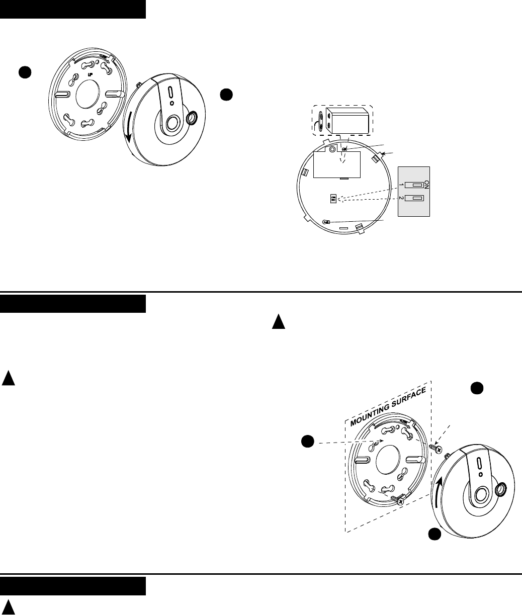
2 D-303363 MCT-442 SMA Installation Guide
3. PREPARATIONS
3.1 Disassembly
BRACKET
DETECTOR
1
Hold the
bracket with
one hand
2
Rotate the
detector as
shown and
pull it from
the bracket
Figure 2. Separating the Detector from Its Bracket
3.2 Communication Format Selection
Verify that the function selector switch 1 is set to ON (UL
communication format). (see figure 3). Note: Switch 2 is not used.
3.3 Pairing/Defaulting the Detector
Note: It is much easier to carry out this operation while holding
the detector in your hand, close to the control panel.
To pair the detector to the control panel, you must set it to pairing
mode.
A. Press and hold down the detector’s tamper switch.
B. Insert the battery into the sensor. Wait for the RF
module’s green LED to light.
C. Release the tamper switch and press it again within 4
seconds. When the sensor is in pairing mode, the green
LED starts to blink.
D. Complete the pairing procedure on the control panel
(see the pairing instructions in the control panel’s
installation guide).
Battery cover
Function selector:
Sw. 1 ON = UL
Sw. 1 OFF = EN
9 volts
Open battery cover and
connect the battery to its
terminals (without insulator).
Verify proper polarity.
Tamper switch
actuator
Tab (1 of 4)
Red button
Figure 3. Detector Rear Side
4. INSTALLATION
4.1 Mounting
The detector can be mounted on a wall or ceiling.
It must be mounted with its bracket (when it is attached to its
bracket the tamper switch is pressed and the detector automatic
reset is performed).
! Warnings
Installation must be performed by a qualified individual. Failure
to properly install, test and maintain a CO detector may cause
it to fail, resulting in loss of life!
Installation of the CO detector should not be used as a substitute
for proper installation, use and maintenance of fuel burning
appliances, including appropriate ventilation and exhaust systems.
Unauthorized removal of the unit from the bracket will initiate a
tamper alert!
The battery must be inserted into the detector otherwise you
will not be able to close the detector.
4.2 Test
A. Local Test
Press the test button (see fig. 1) until the built-in buzzer sounds 1
beep and the red, green and yellow LEDs flash sequentially (see
section 2 - SPECIFICATION). This means that the local test is
successful. If additional or other signals exist, refer to section 2 -
SPECIFICATION.
! WARNING: The test switch is the only proper way to test the
CO detector. Never use vehicle exhaust! Exhaust may cause
permanent damage and void your warranty.
B. Communication Test
Create a tamper alarm at the installation location and verify that
tamper message is received by the control panel / receiver.
1
Locate the bracket on
mounting surface so
that the word “UP” is
located as shown (so
that the detectors
stickers text will be
easily readable)
Mark and drill 2 holes in
mounting surface. Fasten
the bracket to the mounting
surface with 2 screws.
Align detector’s tabs (see figure 3) with the bracket
slots and rotate the detector as shown. Pull the
detector outward to verify that it is securely attached.
2
3
UP
Figure 4. Mounting the MCT-442 SMA
5. MAINTENANCE
! Warning: Press the detector's TEST button once every
week to ensure proper operation of the detector.
When low battery alarm exists (see specifications) immediately
replace the battery (see figure 3).
Once a month, use vacuum cleaner to clean the air vents
occasionally, to keep them free of dust.
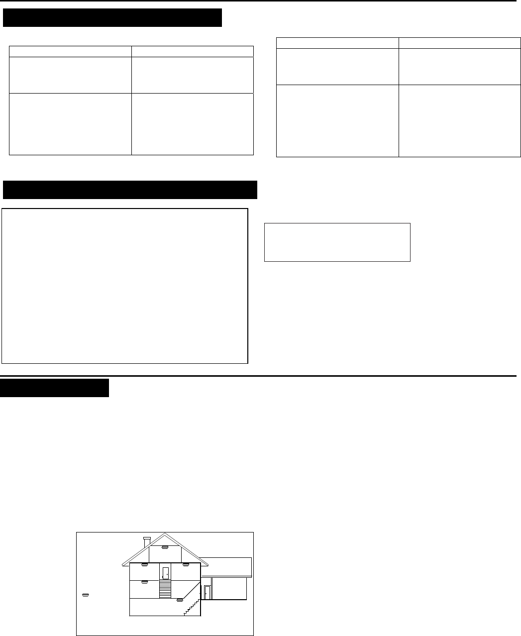
D-303363 MCT-442 SMA Installation Guide 3
6. TROUBLESHOOTING
If you encounter one of the following problems with the MCT-442
SMA, perform the suggested remedy:
Problem Remedy
Attempt to pair the detector is
unsuccessful. Make sure that the detector
has been defaulted and is set
to pairing mode (see section
3.3).
The detector and the panel do
not communicate. Perform the signal strength
testing procedure described in
the control panel installation
manual. Make sure that the
signal is sufficient. If
necessary, replace the
detector’s battery.
Problem Remedy
The detector sends a Low
Battery indication. To ensure continuous proper
operation, replace the battery
within two weeks of the first
Low Battery indication.
Panel does not arm because of
an unrecognized detector
malfunction
Consult with your installer or
system provider before you
disable a zone.
Disable the sensor zone (see
the control panel user manual).
Note that disabling a detector
zone lowers the overall
securit
y
level of
y
our s
y
stem.
7. COMPLIANCE WITH STANDARDS
FCC
This device complies with Part 15 of the FCC Rules and RSS-210 of
Industry and Science Canada. Operation is subject to the following two
conditions: (1) This device may not cause harmful interference, and (2) this
device must accept any interference received, including interference that
may cause undesired operation.
This device complies with Industry Canada license-exempt RSS
standard(s). Operation is subject to the following two conditions: (1) this
device may not cause interference, and (2) this device must accept any
interference, including interference that may cause undesired operation of
the device.
Le présent appareil est conforme aux CNR d'Industrie Canada
applicables aux appareils radio exempts de licence. L'exploitation est
autorisée aux deux conditions suivantes : (1) l'appareil ne doit pas
produire de brouillage, et (2) l'utilisateur de l'appareil doit accepter tout
brouillage radioélectrique subi, même si le brouillage est susceptible
d'en compromettre le fonctionnement.
Visonic Ltd, M/N: E203826
FCC ID: WP3ZBT
IC: 1467C-ZBT
ANSI/UL
Complies with ANSI/UL 639, ULC – S306
APPENDICES
Appendix A - CO Detector Installation Overview
A-1. Selecting Installation Location
Selecting a suitable location is critical for the CO detector. The
Consumer Product Safety Commission (CPSC) recommends to
use at least one CO detector per household, located near as
possible to sleeping area of the home, because the human body
is most vulnerable to the CO gas effect during sleeping hours.
For added protection, install additional CO detector in every separate
bedroom and on every level of your home. If your bedroom hallway is
longer than 14 meters (40 feet), install a CO detector at BOTH ends
of the hallway. Install an additional detector 6 meters (20 feet) away
from the furnace or fuel burning heat source.
For maximum
protection, the
detector should
be also located
outside primary
sleeping areas or
at each level of
your home. Mount
the detector on a
firm wall or ceiling
(see par. 4.1).
BEDROOM
BEDROOM BEDROOM
LIVING
ROOM
KITCHEN
BASEMENT
GARAGE
CO DETECTOR
Figure 5. CO Detectors locations in a
Mult
i
-
Floor Residence
A-2. Where Not to Install CO Detectors
1. In location where temperature may be below -10C (14F) or
above 40C (104F).
2. In locations where humidity is below 10% or above 93% RH.
3. Near paint thinner fumes.
4. Near air conditioners, furnaces, stoves, fireplaces and any
other ventilation source that may interfere with the CO gas
entering the detector.
5. In locations where furniture or draperies may obstruct the air flow.
6. In exhaust streams from gas engines, vents, flues or
chimneys.
7. Where dirt or dust could collect and block the sensor and stop
its working.
8. In locations that can be reached by children.
9. In turbulent air from ceiling fans.
10. In close proximity to an automobile exhaust pipe - this will
damage the detector.
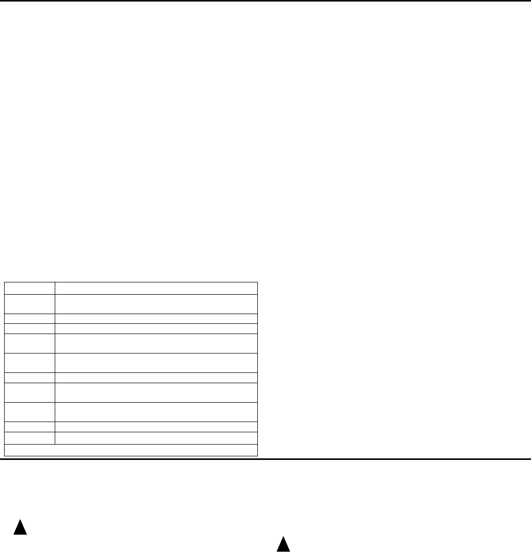
4 D-303363 MCT-442 SMA Installation Guide
Appendix B - CO Gas Health Effects
B-1. Toxic Effects
Carbon monoxide (CO) is a colorless, odorless non-irritating gas
which is classified as a chemical asphyxiate whose toxic action is a
direct result of the hypoxia produced by a given exposure.
CO is rapidly absorbed through the lungs, diffuses across the alveolar
capillary membrane and is reversible bound with hemoglobin as
carboxyheoglobin (COHb), however a minute amount is present in
the plasma. The affinity of hemoglobin for CO is over 200 times its
affinity for oxygen. This reduces the oxygen carrying of the blood and
also has an effect on dissociation of oxyhemoglobin which farther
reduces the oxygen supply to the tissues. CO is chemically
unchanged in the body and is eliminated in the expired air. The
elimination is determined by the same factors that applied during
absorption.
If the Co level in the inhaled air is constant, the level of COHb in the
blood will approach an equilibrium state after several hours. However,
the rate at which the equilibrium is reached depends on many factors,
e.g. lung ventilation rate (physical activity) and alveolar capillary
transfer, cardiac parameters, blood hemoglobin concentration,
barometric pressure, oxygen and carbon dioxide concentration in the
inhaled air, but the two most important factors in determining the
COHb level are the CO concentration and the duration of exposure.
The effects of different saturation blood COHb levels on healthy
adults are shown in table A1.
Table 1 - Health effects of COHb blood levels on healthy adults
% COHb Effects
03 - 0.7 Normal range in non-smokers due to endogenous
production
0.7 - 2.9 No proven physiological changes
2.9 - 4.5 Cardio-vascular changes in cardiac patients
4 - 6 Usual values observed in smokers, impairment in
psychomotor tests
7 - 10 Cardio-vascular changes in non-cardiac patients
(increased cardiac output and coronary blood flow)
10 - 20 Slight headache, weakness, potential burden on fetus
20 - 30 Severe headache, nausea, impairment in limb
movements
30 - 40 Severe headache. irritability, confusion, impairment in
visual acuity, nausea, muscular weakness, dizziness
40 -50 Convulsions and unconsciousness
60 - 70 Coma, collapse, death
Source: US Environmental Protection Agency 1984
The following symptoms are related to CO poisoning and are to be
discussed with ALL members of the household:
1. Mild Exposure: Slight headache, nausea, vomiting, fatigue (often
described as "Flu-like" symptoms).
2. Medium Exposure: Severe throbbing headache, drowsiness, fast
heart rate.
3. Extreme Exposure: Unconsciousness, convulsions, cardio
respiratory failure, death.
4. Many cases of reported CO poisoning indicate that while victims
are aware they are not well, they become so disordered they are
unable to save themselves by either exiting the building or calling
for assistance. Young children and household pets are typically
first affected.
B-2. Chronic Effects on High Risk Group
Individuals with coronary artery disease exposed to low levels of CO
showed reduced ability to exercise. The time of onset of exercise-induced
angina pectoris in such patients exposed to low levels of CO is reduced.
Carbon monoxide readily crosses the placental barrier and may endanger
the normal development of the fetus.
A number of high risk groups are particularly sensitive to the effects of
CO because of various organ impairments or specific changes,
mainly:
a. Those whose oxygen carrying capacity is decreased due to anemia
or other hemoglobin disorders.
b. Those with increased oxygen needs such as those encountered in
fever, hyperthyroidism or pregnancy.
c. Those with systematic hypoxia due to respiratory insufficiency.
d. Those with hearth disease and any vascular insufficiency, such as
cerebral ischaemia and peripheral vascular diseases.
B-3. Normal COHb levels
Under normal conditions all humans have low levels of COHb of
between 0.3% and 0.7% present within the body. These levels are
considered neither beneficial nor harmful.
B-4. Tobacco Smoking
Tobacco smokers are exposed to significant concentration of CO. In
cigarette smokers the COHb concentration varies between 5% - 9%
while heavy smokers it may exceed 10%.
Appendix C - Action to Take When Alarm Sounds
In case of harmful levels of CO gas is detected, your detector will go
into continuous full alarm, Try to take the following necessary actions
immediately:
1. Push the detector TEST switch to silence the alarm.
! Warning: Never remove the battery to silence the alarm.
Removing the battery removes your protection!
2. Call your emergency service (tel. No. .............), or fire department
(tel. No. ............). (Please write the telephone numbers).
3. Immediately move to fresh air - outdoors or by opening
door/window. Do a head count to check that all persons are
accounted for. Do not reenter the premises nor move away from
the open door/window until the emergency services responders
have arrived, the premises have been aired out, and your alarm
remains in normal condition.
4. After following steps 1 - 3, if your alarm reactivates within 24 hours
period, repeat steps 1 - 3 and call qualified technician (Tel. No.
........) to investigate for sources of CO gas from fuel burning
equipment and appliances, and inspect for proper operation of this
equipment. If problems are identified during this inspection, have
the equipment serviced immediately. Note any combustion
equipment not inspected by the technician and consult the
manufacturer instructions, or contact the manufacturers directly,
for more information about CO safety and this equipment. Make
sure that motor vehicles are not, and have not been, operating in
an attached garage or adjacent to the residence.
! Warning: Normally an activation of the detector indicates the
presence of CO gas. However, the CO gas can be extremely fatal, if it
is not detected. The source of the CO gas may come from several
possible situations.
Caution: This detector will only indicate the presence of CO gas at
the sensor. However, you have to be aware that the CO gas may be
present in other areas in the premises.
Action to be taken after the problem has been corrected
Once the problem about the CO gas presence in the premises has
been corrected, the detector's alarm should be off. After waiting for 10
minutes, push the Test button, to verify that the detector is properly
working again.
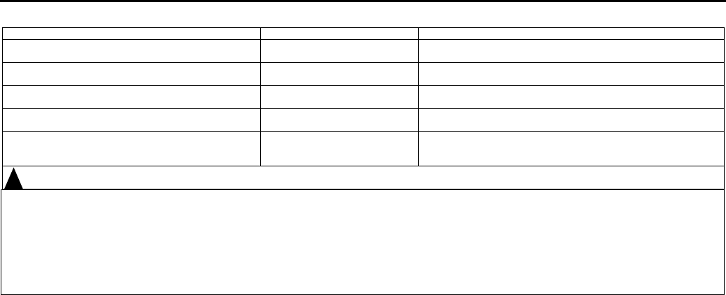
D-303363 MCT-442 SMA Installation Guide 5
Appendix D - Warnings and Limitations
This product is intended for use in ordinary indoor locations of family living
units. It is not designed to measure compliance with Occupational Safety
and Health Administration (OSHA) commercial or industrial standards.
Caution: The detector will only indicate the presence of carbon monoxide
gas at the sensor. Carbon monoxide gas may be present in other areas.
Individuals with medical problems may consider using warning devices
which provide audible and visual signals for carbon monoxide
concentrations under 30 ppm.
The alarm, including the sensor, is not to be located within 1.5m (5 feet) of
any cooking appliance.
The detector may not alarm at low carbon monoxide levels. The
Occupational Safety and Health Association (OSHA) has established that
continuous exposure levels of 50 ppm should not be exceeded in an 8
hours period. Individuals with medical problem may consider more
sensitive detection devices.
The CO gas detector is not suitable as a smoke detector or fire detector.
This detector is not suitable to install in an hazardous location as defined
in National Electrical Code.
Carbon monoxide must reach the detector for proper performance of CO
gas detection. The detector may not protect people who are at special risk
from carbon monoxide exposure by reason of age, pregnancy or medical
condition. In doubt, consult your medical practitioner.
CO detectors may wear out because they contain electronic parts that fail
at any time. Test your detector at least every week.
Instruct children never to play with the detector.
Never use detergents or other solvents to clean the detector.
Avoid spraying air fresheners, hair spray, paint or other aerosols near the
detector.
Do not paint the detector. Paint will seal the detectors vents and interfere
detecting CO gas.
Detailed information on conditions which can result in transient CO
situations:
1. Excessive spillage or reverse venting of fuel burning appliances
caused by:
a. Outdoor ambient conditions such as wind direction and/or velocity,
including high gusts of wind; heavy air in the vent pipes (cold/humid
air with extended periods between cycles).
b. Negative pressure differential resulting from the use of exhaust
fans.
c. Simultaneous operation of several fuel burning appliances
competing for limited internal air.
d. Vent pipe connection vibrating loose from clothes dryers, furnaces,
or water heaters.
e. Obstructions in or unconventional vent pipe designs which amplify
the above situations.
2. Extended operation of unvented fuel burning devices (range, oven,
fireplace, etc.).
3. Temperature inversions which can trap exhaust gasses near the ground.
4. Car idling in an open or closed attached garage, or near a home.
Appendix E - Trouble-shooting
Problem This means...
Y
ou should...
Every 60 seconds, the yellow LED flashes once and 1
beep is heard. Low battery warning Replace battery (see SPECIFICATIONS).
When TEST/MUTE button is pressed, the green LED
flashes instead of li
g
htin
g
durin
g
2 seconds. Detector fault o
r
the battery is
not OK. Replace battery (see SPECIFICATIONS). If the problem still
exists, replace detecto
r
.
Every 60 seconds, there are 3 flashes of the yellow
LED and 1 beep is heard. Detector end of life/ fault. Replace battery (see SPECIFICATIONS). If the problem still
exists, replace detector.
CO detector goes back into alarm 6 minutes after the
TEST/MUTE button is pressed. CO level indicates a potentially
dan
g
erous situation. If you are feeling symptoms of CO poisoning, evacuate your
home and call
y
our emer
g
enc
y
service.
CO detector alarms frequently even though no high
levels of CO are revealed in an investigation. The CO detector may be
improperly located. Relocate the detector - see appendix A. If frequent alarms
continue, have home rechecked for potential CO problems. You
may experiencing an intermittent CO problem.
! Warning! Changes or modifications to this equipment not expressly approved by Visonic Ltd. could void the user’s authority to operate the equipment.
The digital circuit of this device has been tested and found to comply with the limits for a Class B digital device, pursuant to Part 15 of the FCC Rules.
These limits are designed to provide reasonable protection against harmful interference in residential installations. This equipment generates, uses and
can radiate radio frequency energy and, if not installed and used in accordance with the instructions, may cause harmful interference to radio and
television reception. However, there is no guarantee that interference will not occur in a particular installation. If this device does cause such interference,
which can be verified by turning the device off and on, the user is encouraged to eliminate the interference by one or more of the following measures:
– Re-orient or re-locate the receiving antenna.
– Increase the distance between the device and the receiver.
– Connect the device to an outlet on a circuit different from the one which supplies power to the receiver.
– Consult the dealer or an experienced radio/TV technician.
6 D-303363 MCT-442 SMA Installation Guide
WARRANTY
Visonic Limited (the “Manufacturer") warrants this product only (the "Product") to the original purchaser only (the
“Purchaser”) against defective workmanship and materials under normal use of the Product for a period of
twelve (12) months from the date of shipment by the Manufacturer.
This Warranty is absolutely conditional upon the Product having been properly installed, maintained and
operated under conditions of normal use in accordance with the Manufacturers recommended installation and
operation instructions. Products which have become defective for any other reason, according to the
Manufacturers discretion, such as improper installation, failure to follow recommended installation and
operational instructions, neglect, willful damage, misuse or vandalism, accidental damage, alteration or
tampering, or repair by anyone other than the manufacturer, are not covered by this Warranty.
The Manufacturer does not represent that this Product may not be compromised and/or circumvented or that the
Product will prevent any death and/or personal injury and/or damage to property resulting from burglary,
robbery, fire or otherwise, or that the Product will in all cases provide adequate warning or protection. The
Product, properly installed and maintained, only reduces the risk of such events without warning and it is not a
guarantee or insurance that such events will not occur.
THIS WARRANTY IS EXCLUSIVE AND EXPRESSLY IN LIEU OF ALL OTHER WARRANTIES,
OBLIGATIONS OR LIABILITIES, WHETHER WRITTEN, ORAL, EXPRESS OR IMPLIED, INCLUDING ANY
WARRANTY OF MERCHANTABILITY OR FITNESS FOR A PARTICULAR PURPOSE, OR OTHERWISE. IN
NO CASE SHALL THE MANUFACTURER BE LIABLE TO ANYONE FOR ANY CONSEQUENTIAL OR
INCIDENTAL DAMAGES FOR BREACH OF THIS WARRANTY OR ANY OTHER WARRANTIES
WHATSOEVER, AS AFORESAID.
THE MANUFACTURER SHALL IN NO EVENT BE LIABLE FOR ANY SPECIAL, INDIRECT, INCIDENTAL,
CONSEQUENTIAL OR PUNITIVE DAMAGES OR FOR LOSS, DAMAGE, OR EXPENSE, INCLUDING LOSS
OF USE, PROFITS, REVENUE, OR GOODWILL, DIRECTLY OR INDIRECTLY ARISING FROM
PURCHASER’S USE OR INABILITY TO USE THE PRODUCT, OR FOR LOSS OR DESTRUCTION OF
OTHER PROPERTY OR FROM ANY OTHER CAUSE, EVEN IF MANUFACTURER HAS BEEN ADVISED OF
THE POSSIBILITY OF SUCH DAMAGE.
THE MANUFACTURER SHALL HAVE NO LIABILITY FOR ANY DEATH, PERSONAL AND/OR BODILY INJURY
AND/OR DAMAGE TO PROPERTY OR OTHER LOSS WHETHER DIRECT, INDIRECT, INCIDENTAL,
CONSEQUENTIAL OR OTHERWISE, BASED ON A CLAIM THAT THE PRODUCT FAILED TO FUNCTION.
However, if the Manufacturer is held liable, whether directly or indirectly, for any loss or damage arising under
this limited warranty, THE MANUFACTURER'S MAXIMUM LIABILITY (IF ANY) SHALL NOT IN ANY CASE
EXCEED THE PURCHASE PRICE OF THE PRODUCT, which shall be fixed as liquidated damages and not as
a penalty, and shall be the complete and exclusive remedy against the Manufacturer.
When accepting the delivery of the Product, the Purchaser agrees to the said conditions of sale and warranty
and he recognizes having been informed of.
Some jurisdictions do not allow the exclusion or limitation of incidental or consequential damages, so these
limitations may not apply under certain circumstances.
The Manufacturer shall be under no liability whatsoever arising out of the corruption and/or malfunctioning of any
telecommunication or electronic equipment or any programs.
The Manufacturers obligations under this Warranty are limited solely to repair and/or replace at the
Manufacturer’s discretion any Product or part thereof that may prove defective. Any repair and/or replacement
shall not extend the original Warranty period. The Manufacturer shall not be responsible for dismantling and/or
reinstallation costs. To exercise this Warranty the Product must be returned to the Manufacturer freight pre-paid
and insured. All freight and insurance costs are the responsibility of the Purchaser and are not included in this
Warranty.
This warranty shall not be modified, varied or extended, and the Manufacturer does not authorize any person to
act on its behalf in the modification, variation or extension of this warranty. This warranty shall apply to the
Product only. All products, accessories or attachments of others used in conjunction with the Product, including
batteries, shall be covered solely by their own warranty, if any. The Manufacturer shall not be liable for any
damage or loss whatsoever, whether directly, indirectly, incidentally, consequentially or otherwise, caused by the
malfunction of the Product due to products, accessories, or attachments of others, including batteries, used in
conjunction with the Products. This Warranty is exclusive to the original Purchaser and is not assignable.
This Warranty is in addition to and does not affect your legal rights. Any provision in this warranty which is
contrary to the Law in the state or country were the Product is supplied shall not apply.
Warning:The user must follow the Manufacturer’s installation and operational instructions including testing the
Product and its whole system at least once a week and to take all necessary precautions for his/her safety and
the protection of his/her property. 1/08
W.E.E.E. Product Recycling Declaration
For information regarding the recycling of this product you must contact the company from which you orignially purchased it. If you are discarding this product and not
returning it for repair then you must ensure that it is returned as identified by your supplier. This product is not to be thrown away with everyday waste.
Directive 2002/96/EC Waste Electrical and Electronic Equipment.
VISONIC LTD. (ISRAEL): P.O.B 22020 TEL-AVIV 61220 ISRAEL. PHONE: (972-3) 645-6789, FAX: (972-3) 645-6788
VISONIC INC. (U.S.A.): 65 WEST DUDLEY TOWN ROAD, BLOOMFIELD CT. 06002-1376. PHONE: (860) 243-0833, (800) 223-0020. FAX:
(860) 242-8094
VISONIC LTD. (UK): UNIT 6 MADINGLEY COURT CHIPPENHAM DRIVE KINGSTON MILTON KEYNES MK10 0BZ.
TEL.: +44(0)845 0755800 FAX: +44(0)845 0755801 PRODUCT SUPPORT: +44(0)845 755802
VISONIC IBERICA: ISLA DE PALMA, 32 NAVE 7, POLÍGONO INDUSTRIAL NORTE, 28700 SAN SEBASTIÁN DE LOS REYES, (MADRID),
ESPAÑA. TEL (34) 91659-3120, FAX (34) 91663-8468. www.visonic-iberica.es
INTERNET: www.visonic.com
VISONIC LTD. 2011 MCT-442 SMA D-303363 Rev 3 (10/11)
Product
Certificate Number 512e/01
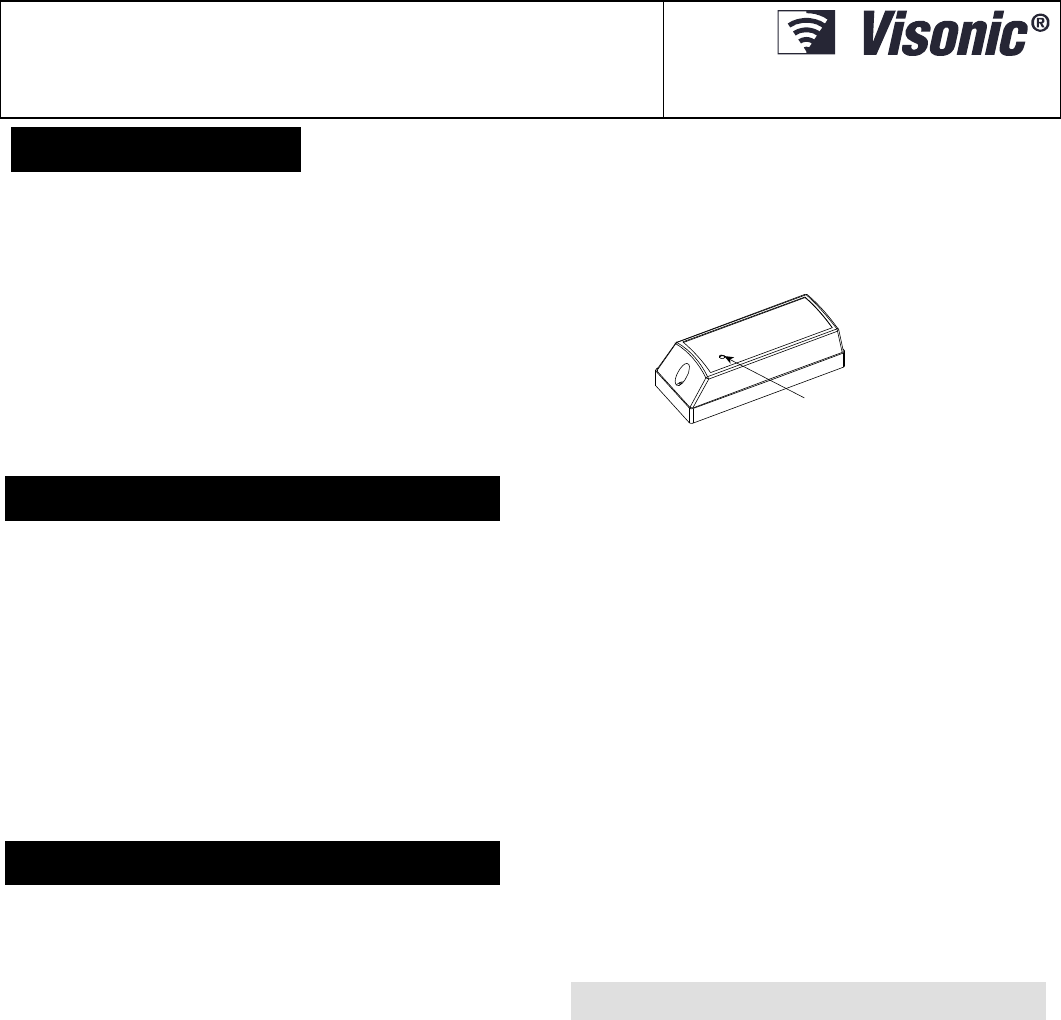
D-303362 MCT-550 SMA Installer's Guide 1
MCT-550 SMA
Supervised Wireless Flood Detector
Installation Instructions
1. INTRODUCTION
The MCT-550 SMA is a fully supervised indoor wireless flood
detector, used to detect the presence of water based fluids at
any desired location.
The MCT-550 SMA transmitter is designed for wall mounting.
The flood sensor is placed in a location where the presence of
water based fluids, as a result of leakage or flooding, is probable.
Upon flood detection, a digital message is transmitted, composed of
the detectors’ ID followed by various status and other messages.
Alarm and other data are thus forwarded to the alarm system.
An on-board tamper switch is opened when the cover is
removed. In a tamper situation, a tamper message is
transmitted.
A periodic supervision message is transmitted automatically (see
specifications) to inform the alarm system at regular intervals, of
the unit’s active participation in the system.
An LED lights whenever alarm or tamper events are reported. The
LED does not light while a supervision message is being
transmitted.
Operating power is obtained from an on-board 3 V Lithium battery.
A weak battery will cause a “low battery” report to be added to any
message transmitted.
TRANSMISSION LED
Fig. 1 - MCT-550 SMA
2. SPECIFICATIONS
Frequency: 2.4 Ghz as per IEEE 802.15.4
Message Repetition: One-shot transmission (default) or once
every 3 minutes (selectable).
Supervision: Signaling at 24-minute intervals.
Response to Tamper Event: Tamper report every 3 minutes
(until the tamper switch is restored).
Power Source: 3V Lithium battery, Panasonic/GP/Sanyo type CR2
or equivalent.
Note: Dispose of used batteries according to the manufacturer's
instructions.
Nominal Battery Capacity: 750 mAh
Current Drain: 6µA STBY, Maximum 100mA during transmission
Battery Life with LED on: 3 years (for typical use)
Note: Inability to connect with wireless network, or wireless link
quality no higher than 20% may significantly reduce the expected
battery life.
Battery Supervision: Automatic reporting of battery condition
data as part of any transmission.
ALARM REPORT:
Every 20 sec. for the first 3 minutes.
Every 3 min. for the next 27 minutes.
After this period the supervision message will include alarm
signal until the event comes to an end.
Length of Flood Sensor Cable: 3 meters (10 ft)
Weight of Flood Sensor Cable: Approx. 60 gr.
Operating Temperature: 0C to 49C (32F to 120F).
Dimensions: 81 x 22 x 23.5 mm (3-3/16 x 7/8 x 15/16 in.).
Weight (including battery, without cable): 45 g (1.6 oz)
Standards: USA: CFR 47 part 15, Canada: RSS 210.
ANSI/UL 639, ULC – S306
3. INSTALLATION
A. Attach the flood sensor near the floor.
B. Secure the flood sensor and its cable to the wall using the three
wire clamps. One clamp should be fastened immediately above
the flood sensor. The flood sensor should be installed only in a
vertical position, and facing downward. The remaining two
clamps can be used as required (Figures 2 and 3).
Note: To provide better protection against rats, it is recommended
that the flood sensor cable be placed inside a metal/plastic pipe.
C. Attach the transmitter to the wall. The transmitter should be
placed as high up as possible on the wall to improve
communication and to prevent the transmitter itself from coming
into contact with water in the event of flooding.
D. Remove the case closure screw (Figure 4), then remove the
unit's cover (Figure 5).
E. Flex out the circuit board retainer (Figure 6) and detach the
circuit board from the base.
F. Hold the base against the mounting surface and mark the 2
drilling points through the mounting holes.
G. Drill the holes and fix the base to the wall using the 2 screws
with countersunk heads supplied in the package.
CAUTION! Screws with other type or size of head may short
circuit the bottom side of the printed circuit board.
H. Insert the edge of the P.C. board with the RF module into the
edge supports, and press the other edge against the flexible
retainer until it snaps home with a click.
I. Clamp the two wires of the flood sensor cable into the
auxiliary input terminals, as shown in Figure 7 (the wires can
be inserted in any order).
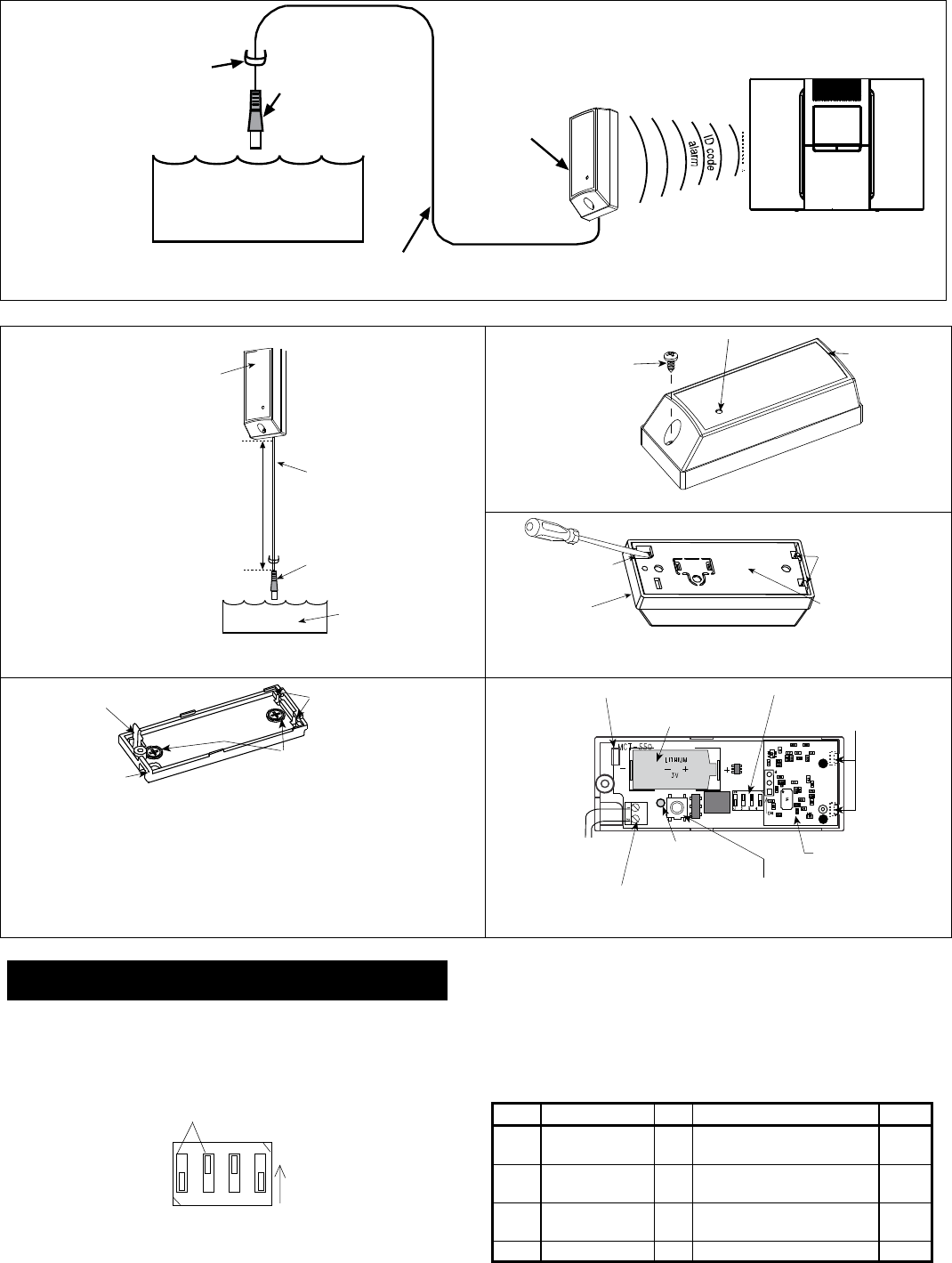
2 D-303362 MCT-550 SMA Installer's Guide
MCT-550
FLOOD SENSOR CABLE
The MC
T
-550 transmits a coded alarm message immediatel
y
following detection of water contact with the food senso r.
CLAMP (1 OF 3)
Attach slightly above Flood Sensor
WATER
ALARM SYSTEM
FLOOD SENSOR
Fig. 2 – Using the MCT-550 SMA
N
ote: Flood sensor height according to
r
equired food detection. Recommende
d
0-3cm from fo
o
r.
TRANSMITTER
FLOOD SENSOR CABLE
2 - 3 m (recommended length)
FLOOD SENSOR
WATER
Fig. 3 – Correct Mounting of the Flood Detector
CLOSURE SCREW
TRANSMISSION LE
D
COVER
Fig. 4 – Removing the Case Closure Screw
BASE WITHP.C. BOARD
WIRING INLET
COVER
BASE CATCHES
Fig. 5 – Separating the Cover from the Base
WIRING INLET
FLEXIBLE RETAINER P.C.BOARD EDGE SUPPORTS
MOUNTING SCREWS
Fig. 6 – Base with P.C. Board Removed
FUNCTIONSELECTOR
TRANSMITTERRF MODULE
TAMPERSWITCH
AUX. INPUT TERMINALS
3 V LITHIUMBATTERY
LED
FLEXIBLERET
A
INER
P.C. BOARDSUPPORTS
W
IRESTO FLOOD SENSOR
Fig. 7 – P.C. Board
4. PREPARATION FOR USE
4.1 The Function Switches
A. Switch Functions
The MCT-550 SMA has a 4-position DIP switch function selector
(see Figure 8).
on
12 43
FIXED SETTINGS
ON
Fig. 8 – Function Selector
B. Setting the Switches
Set the function switches as desired prior to applying power. Use a
ball point pen or other pointed object to shift the switch levers. The
ON position is indicated by the arrow on the switch body.
Table 1. Getting acquainted with the function selector
Sw- Function Pos. Selected Option Default
SW1 - -
SW1 should remain always in
OFF position
OFF
SW2 - -
SW2 should remain always in
ON position
ON
SW3 Restore reports
enable/disable
ON
OFF Restore events reported
Restore events not reported
ON
SW4 - - - -
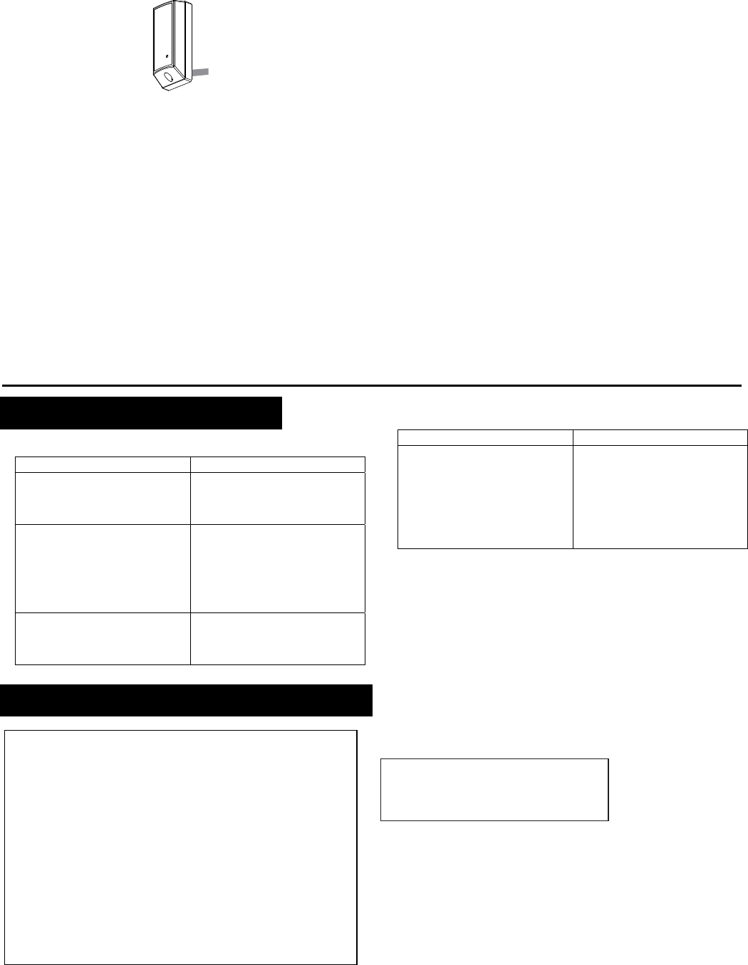
D-303362 MCT-550 SMA Installer's Guide 3
4.2 Activating the Detector
To activate, pull the strip that protrudes from the back of the
detector.
Fig. 9 – Activation Strip
4.3 Pairing/Defaulting the Detector
To pair the detector to the control panel, you must set it to pairing
mode.
A. Press and hold down the detector’s tamper switch.
B. Insert the battery into the detector. Wait for the RF
module’s green LED to light.
C. Release the tamper switch and press it again within 4
seconds. When the detector is in pairing mode, the
green LED starts to blink.
D. Complete the pairing procedure on the control panel
(see the pairing instructions in the control panel’s
installation guide).
4.4 Testing the Unit
Before testing, set DIP switches SW3 and SW4 as required for
the particular application (see Para. 4.1).
A. Insert the battery between the battery clips, at the correct
polarity. For proper operation, only Lithium battery
(Panasonic type CR-2 or equivalent) should be used.
B. Press the tamper switch once and release it.
Note: Since the cover is removed and power is applied, a
tamper situation exists. Verify that the MCT-550 SMA
transmits (the LED lights briefly) once every 3 minutes,
regardless of SW4 setting.
C. When you are satisfied that tamper alerts are transmitted
properly, put the cover on to return the tamper switch to its
normal (undisturbed) position. Wait slightly over 3 minutes to
verify that tamper transmissions cease. If all went well, secure
the front cover to the base with the case closure screw.
D. Clean the flood sensor thoroughly with a rag. Bring the flood
sensor into contact with water and verify that the transmitter
LED lights, indicating that transmission is in progress. If SW4
is ON, wait 3 minutes to verify that the transmission is
repeated at 3-minute intervals.
E. Dry the flood sensor using either blotting paper or a rag, thus
restoring it to the undisturbed state and observe the LED. If
SW3 is set to ON, a “restore” transmission will now take place.
F. Refer to the target receiver’s installation instructions, and let
the receiver “learn” the ID code associated with the detector.
4.5 Maintenance
To ensure proper detector's operation, clean the flood sensor
thoroughly with a rag once a month and perform test.
5. TROUBLESHOOTING
If you encounter one of the following problems with the MCT-550
SMA, perform the suggested remedy:
Problem Remed
y
Attempt to pair the detector is
unsuccessful. Make sure that the detector
has been defaulted and is set
to pairing mode (see section
4.3).
The detector and the panel do
not communicate. Perform the signal strength
testing procedure described in
the control panel installation
manual. Make sure that the
signal is sufficient. If
necessary, replace the
detector’s battery.
The detector sends a Low
Battery indication. To ensure continuous proper
operation, replace the battery
within two weeks of the first
Low Battery indication.
Problem Remed
y
Panel does not arm because of
an unrecognized detector
malfunction
Consult with your installer or
system provider before you
disable a zone.
Disable the detector zone (see
the control panel user manual).
Note that disabling a sensor
zone lowers the overall security
level of your system.
6. COMPLIANCE WITH STANDARDS
FCC
This device complies with Part 15 of the FCC Rules and RSS-210 of
Industry and Science Canada. Operation is subject to the following two
conditions: (1) This device may not cause harmful interference, and (2) this
device must accept any interference received, including interference that
may cause undesired operation.
This device complies with Industry Canada license-exempt RSS
standard(s). Operation is subject to the following two conditions: (1) this
device may not cause interference, and (2) this device must accept any
interference, including interference that may cause undesired operation of
the device.
Le présent appareil est conforme aux CNR d'Industrie Canada
applicables aux appareils radio exempts de licence. L'exploitation est
autorisée aux deux conditions suivantes : (1) l'appareil ne doit pas
produire de brouillage, et (2) l'utilisateur de l'appareil doit accepter tout
brouillage radioélectrique subi, même si le brouillage est susceptible
d'en compromettre le fonctionnement.
Visonic Ltd, M/N: E203826
FCC ID: WP3ZBT
IC: 1467C-ZBT
ANSI/UL
Complies with ANSI/UL 639, ULC – S306

4 D-303362 MCT-550 SMA Installer's Guide
7. MISCELLANEOUS COMMENTS
Visonic Ltd. wireless systems are very reliable and are tested to
high standards. However, due to low transmitting power and
limited range (required by FCC and other regulatory authorities),
there are some limitations to be considered:
A. Receivers may be blocked by radio signals occurring on or
near their operating frequencies, regardless of the digital code
used.
B. A receiver responds only to one transmitted signal at a time.
C. Wireless devices should be tested regularly to determine whether
there are sources of interference and to protect against faults.
The user is cautioned that changes or modifications to the
unit, not expressly approved by Visonic Ltd., could void the
user’s FCC or other authority to operate the equipment.
W.E.E.E. Product Recycling Declaration
For information regarding the recycling of this product you must contact
the company from which you orignially purchased it. If you are discarding
this product and not returning it for repair then you must ensure that it is
returned as identified by your supplier. This product is not to be thrown
away with everyday waste.
European Directive 2002/96/EC Waste Electrical and Electronic Equipmen
t
.
WARRANTY
Visonic Limited (the “Manufacturer") warrants this product only (the "Product") to the original purchaser only (the
“Purchaser”) against defective workmanship and materials under normal use of the Product for a period of twelve
(12) months from the date of shipment by the Manufacturer.
This Warranty is absolutely conditional upon the Product having been properly installed, maintained and operated
under conditions of normal use in accordance with the Manufacturers recommended installation and operation
instructions. Products which have become defective for any other reason, according to the Manufacturers
discretion, such as improper installation, failure to follow recommended installation and operational instructions,
neglect, willful damage, misuse or vandalism, accidental damage, alteration or tampering, or repair by anyone
other than the manufacturer, are not covered by this Warranty.
The Manufacturer does not represent that this Product may not be compromised and/or circumvented or that the
Product will prevent any death and/or personal injury and/or damage to property resulting from burglary, robbery,
fire or otherwise, or that the Product will in all cases provide adequate warning or protection. The Product,
properly installed and maintained, only reduces the risk of such events without warning and it is not a guarantee
or insurance that such events will not occur.
THIS WARRANTY IS EXCLUSIVE AND EXPRESSLY IN LIEU OF ALL OTHER WARRANTIES,
OBLIGATIONS OR LIABILITIES, WHETHER WRITTEN, ORAL, EXPRESS OR IMPLIED, INCLUDING ANY
WARRANTY OF MERCHANTABILITY OR FITNESS FOR A PARTICULAR PURPOSE, OR OTHERWISE. IN
NO CASE SHALL THE MANUFACTURER BE LIABLE TO ANYONE FOR ANY CONSEQUENTIAL OR
INCIDENTAL DAMAGES FOR BREACH OF THIS WARRANTY OR ANY OTHER WARRANTIES
WHATSOEVER, AS AFORESAID.
THE MANUFACTURER SHALL IN NO EVENT BE LIABLE FOR ANY SPECIAL, INDIRECT, INCIDENTAL,
CONSEQUENTIAL OR PUNITIVE DAMAGES OR FOR LOSS, DAMAGE, OR EXPENSE, INCLUDING LOSS
OF USE, PROFITS, REVENUE, OR GOODWILL, DIRECTLY OR INDIRECTLY ARISING FROM
PURCHASER’S USE OR INABILITY TO USE THE PRODUCT, OR FOR LOSS OR DESTRUCTION OF
OTHER PROPERTY OR FROM ANY OTHER CAUSE, EVEN IF MANUFACTURER HAS BEEN ADVISED OF
THE POSSIBILITY OF SUCH DAMAGE.
THE MANUFACTURER SHALL HAVE NO LIABILITY FOR ANY DEATH, PERSONAL AND/OR BODILY
INJURY AND/OR DAMAGE TO PROPERTY OR OTHER LOSS WHETHER DIRECT, INDIRECT, INCIDENTAL,
CONSEQUENTIAL OR OTHERWISE, BASED ON A CLAIM THAT THE PRODUCT FAILED TO FUNCTION.
However, if the Manufacturer is held liable, whether directly or indirectly, for any loss or damage arising under this
limited warranty, THE MANUFACTURER'S MAXIMUM LIABILITY (IF ANY) SHALL NOT IN ANY CASE
EXCEED THE PURCHASE PRICE OF THE PRODUCT, which shall be fixed as liquidated damages and not as a
penalty, and shall be the complete and exclusive remedy against the Manufacturer.
When accepting the delivery of the Product, the Purchaser agrees to the said conditions of sale and warranty and
he recognizes having been informed of.
Some jurisdictions do not allow the exclusion or limitation of incidental or consequential damages, so these
limitations may not apply under certain circumstances.
The Manufacturer shall be under no liability whatsoever arising out of the corruption and/or malfunctioning of any
telecommunication or electronic equipment or any programs.
The Manufacturers obligations under this Warranty are limited solely to repair and/or replace at the
Manufacturer’s discretion any Product or part thereof that may prove defective. Any repair and/or replacement
shall not extend the original Warranty period. The Manufacturer shall not be responsible for dismantling and/or
reinstallation costs. To exercise this Warranty the Product must be returned to the Manufacturer freight pre-paid
and insured. All freight and insurance costs are the responsibility of the Purchaser and are not included in this
Warranty.
This warranty shall not be modified, varied or extended, and the Manufacturer does not authorize any person to
act on its behalf in the modification, variation or extension of this warranty. This warranty shall apply to the
Product only. All products, accessories or attachments of others used in conjunction with the Product, including
batteries, shall be covered solely by their own warranty, if any. The Manufacturer shall not be liable for any
damage or loss whatsoever, whether directly, indirectly, incidentally, consequentially or otherwise, caused by the
malfunction of the Product due to products, accessories, or attachments of others, including batteries, used in
conjunction with the Products. This Warranty is exclusive to the original Purchaser and is not assignable.
This Warranty is in addition to and does not affect your legal rights. Any provision in this warranty which is
contrary to the Law in the state or country were the Product is supplied shall not apply.
Warning: The user must follow the Manufacturer’s installation and operational instructions including testing the
Product and its whole system at least once a week and to take all necessary precautions for his/her safety and
the protection of his/her property.
1/08
VISONIC LTD. (ISRAEL): P.O.B 22020 TEL-AVIV 61220 ISRAEL. PHONE: (972-3) 645-6789, FAX: (972-3) 645-6788
VISONIC INC. (U.S.A.): 65 WEST DUDLEY TOWN ROAD, BLOOMFIELD CT. 06002-1376. PHONE: (860) 243-0833, (800) 223-0020. FAX: (860) 242-8094
VISONIC LTD. (UK): FRASER ROAD, PRIORY BUSINESS PARK, BEDFORD MK44 3WH. TEL.: +44(0)845 0755800 FAX: +44(0)845 0755801
PRODUCT SUPPORT: +44(0)845 755802
VISONIC IBERICA SEGURIDAD, SL: C/ ISLA DE PALMA, 32 - NAVE 7, POLÍGONO INDUSTRIAL NORTE, 28700 SAN SEBASTIÁN DE LOS REYES, (MADRID), ESPAÑA.
TEL (34) 91659-3120, FAX (34) 91663-8468. www.visonic-iberica.com
VISONIC SICHERHEITSTECHNIK GMBH ROMANEYER STR. 31, 51467 BERGISCH GLADBACH, TEL.: 02202-104930 FAX: 02202-104959
INTERNET: www.visonic.com
VISONIC LTD. 2011 MCT-550 SMA D-303362 (REV. 3, 10/11)
D-303361 NEXT® PLUS K9-85 SMA Installation Instructions 1
NEXT® PLUS K9-85 SMA
Wireless Digital Pet Immune PIR Detector
Installation Instructions
1. INTRODUCTION
The NEXT® PLUS K9-85 SMA (pet immune) is a microprocessor-
controlled wireless digital PIR detector.
The detector’s features are as follows:
Cylindrical lens with uniform detection sensitivity throughout its
operating range, up to 15 meters (49 ft).
Target Specific Imaging™ (TSI) technology is used for distinction
between humans and pets weighing up to 38 kg (85lb).
Incorporates an iControl-compatible wireless transceiver.
The advanced True Motion Recognition™ algorithm (patented)
allows distinguishing between the true motion of an intruder and any
other disturbances which may cause false alarms.
Sophisticated frequency domain digital signal processing.
No vertical adjustment is needed.
An on-board motion event jumper determines whether 1 or 2
consecutive motion events trigger an alarm.
After detection, the detector disarms itself to save battery power. It
rearms (reverts to the ready state) if there is no subsequent
detection throughout the following 2-minute period.
Very low current consumption.
Microprocessor-controlled temperature compensation.
Sealed chamber protects the optical system.
Front cover tamper switch.
White light protection.
Elegantly styled, sturdy case.
For UL installations: The detector is for use with UL listed control
unit only. Pet immunity has not been evaluated by UL.
Walk-Test LED
Lens
Fig. 1 - NEXT PLUS K9-85 SMA
2. SPECIFICATIONS
Detector Type: Dual element low-noise pyro-electric sensor.
Lens Data
No. of Curtain Beams: 18 far, 18 mid, 18 close
Max. Coverage: 15 x 15 m, (49 x 49 ft) / 90°
Pet Immunity: Up to 38 kg (85 lb).
ELECTRICAL
Internal Battery: 3V Lithium battery, type CR-123A. For UL installations, use
Panasonic, Sanyo and GP only.
Nominal Battery Capacity: 1450 mAh.
Battery Life (with LED on): Typically over 3 years.
Note: Inability to connect with wireless network, or wireless link
quality no higher than 20% may significantly reduce the expected
battery life.
Battery Power Test: Performed immediately upon battery insertion
and periodically after every several hours.
FUNCTIONAL
True Motion Event Verification: 2 position selector - 1 (OFF) or 2
(ON) motion events.
Alarm Period: 3 seconds
Visual Indications:
LED Lights for about 3 seconds upon transmission of alarm &
tamper messages and upon motion detection in the walk test
mode.
LED Flashes during the power-up stabilization period, or after
restoring (pressing) the tamper switch.
LED Does not light upon transmission of supervision messages.
Rearm Timer: Rearms the detector 2 minutes after the last alarm.
Timer disabled in the walk test mode.
WIRELESS
Frequency: 2.4 Ghz as per IEEE 802.15.4.
Tamper Alert: Reported when a tamper event occurs and in any
subsequent message, until the tamper switch is restored.
Supervision Message: Signaling at 24 minutes interval.
MOUNTING
Height: Up to 2.1 m (7 ft)
Installation Options: Surface or corner.
ACCESSORIES:
BR-1: Surface mounted swivel bracket, adjustable 30° down and 45°
left/45° right.
BR-2: BR-1 with a corner adapter
BR-3: BR-1 with a ceiling adapter
ENVIRONMENTAL
RFI Protection: >20 V/m up to 1000 MHz.
Operating Temperatures: -10°C to 50°C (14°F to 122°F)
Storage Temperatures: -20°C to 60°C (-4°F to 140°F).
COMPLIANCE WITH STANDARDS
USA: CFR 47 part 15, Canada: RSS 210.
ANSI/UL 639, ULC – S306
PHYSICAL
Size (H x W x D): 94.5 x 63.5 x 53.0 mm (3-11/16 x 2-1/2 x 2-1/16”).
Weight (with battery): 70 g (2.5 oz).
Color: White.
PATENTS: U.S. Patents 5,693,943 6,211,522 D445,709 (another
patent pending).
3. INSTALLATION
3.1 General Guidance
12 34 5 6 7
Fig. 2 - General Guidelines
Do not install near
sources of
heating/cooling.
Do not aim at
windows. Do not install
outdoors.
Do not install
where direct
sunlight can strike
the unit.
Do not install near
high-voltage
electrical lines.
Do not install
behind any
obstruction.
Do not mount on
unstable surfaces.
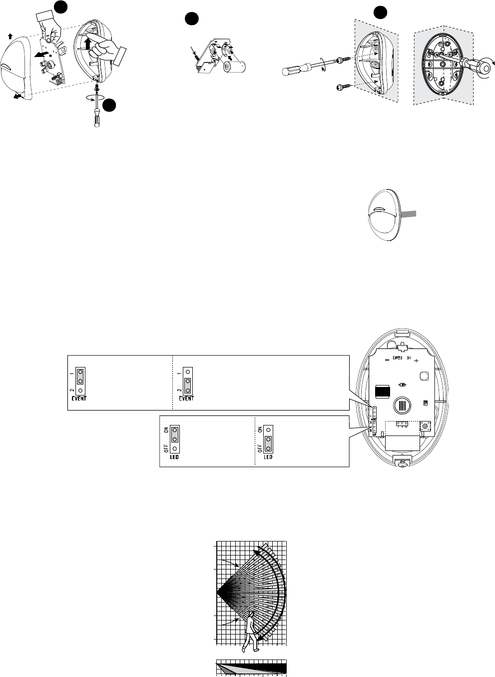
2 D-303361 NEXT® PLUS K9-85 SMA Installation Instructions
3.2 Installation Procedure
1. For battery installation, see steps 1-3 below. 2. For mounting the detector, see step 4 below.
1
2
Push catch and remove board
On surface In corner
4
Mounting
3
Insert battery
Front Tamper switch
Release screw and
remove cover
Fig. 3 – Battery Installation and Mounting
Note: The detector transmits a low battery signal upon detection of
low voltage. It is recommended to wait about 1 minute after battery
removal, before inserting the new battery.
3.3 Activating the Detector
To activate, pull the strip that protrudes from the back of the detector.
Then, close the opening by pasting the supplied sticker over it.
Fig. 3a – Activation Strip
3.3 Pairing the Detector
To pair the detector to the control panel, you must set it to pairing
mode.
1. Press and hold down the detector’s tamper switch.
2. Insert the battery into the detector.
3. Release the tamper switch and press it again within 4 seconds.
4. Complete the pairing procedure on the control panel (see the pairing
instructions in the control panel’s installation guide).
3.4 Jumper Settings
2 events - Highest false alarm protection
1 event - fast response
ON - LED enabled OFF - LED disabled
Fig. 4 - Jumper Settings
3.5 Walk Testing
Walk across the far end of coverage pattern in both directions.
The LED should light for 2-3 seconds each time your motion is
detected.
Important! Instruct the user to walk test at least once a week to
verify proper function of the detector.
5 10 15 m
0
2.1 m
(6.9 ft)
16.4 32.8 49.2 ft
90°
5
0
16.4
0
15 m
49.2 ft
10
32.8
5m
16.4ft
5m
16.4ft
10m
32.8ft
10m
32.8ft
Top view
Side view
Fig. 5 - Coverage Pattern Walk-Test
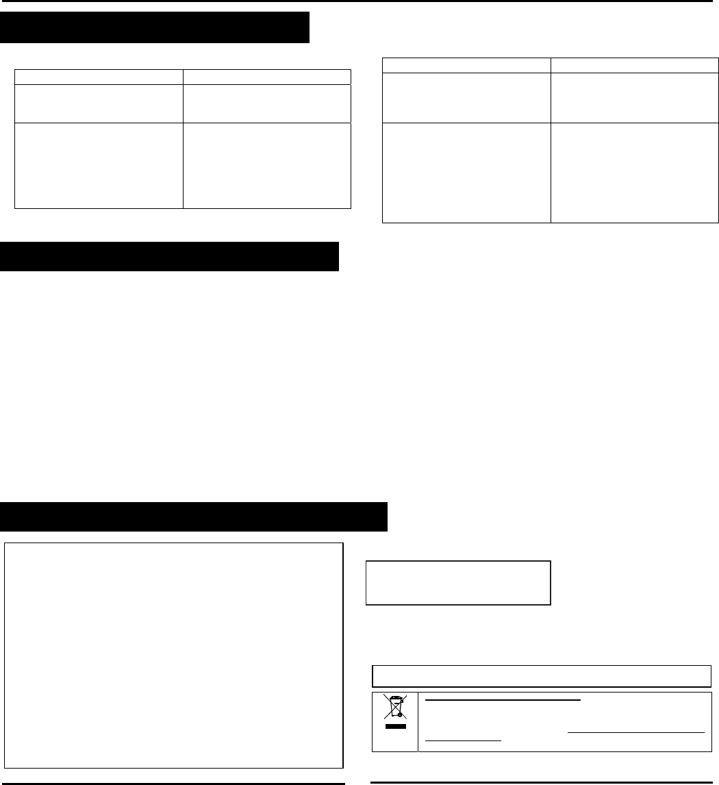
D-303361 NEXT® PLUS K9-85 SMA Installation Instructions 3
4. TROUBLESHOOTING
If you encounter one of the following problems with the NEXT
PLUS K9-85 SMA, perform the suggested remedy:
Problem Remed
y
Attempt to pair the sensor is
unsuccessful. Make sure that the sensor has
been defaulted and is set to
pairing mode (see section 3.5).
The sensor and the panel do
not communicate. Perform the signal strength
testing procedure described in
the control panel installation
manual. Make sure that the
signal is sufficient. If
necessary, replace the
sensor’s battery.
Problem Remed
y
The sensor sends a Low
Battery indication. To ensure continuous proper
operation, replace the battery
within two weeks of the first
Low Battery indication.
Panel does not arm because of
an unrecognized sensor
malfunction
Consult with your installer or
system provider before you
disable a zone.
Disable the sensor zone (see
the control panel user manual).
Note that disabling a sensor
zone lowers the overall security
level of your system.
5. SPECIAL COMMENTS
Even the most sophisticated detectors can sometimes be defeated or
may fail to warn due to: DC power failure / improper connection,
malicious masking of the lens, tampering with the optical system,
decreased sensitivity in ambient temperatures close to that of the
human body and unexpected failure of a component part.
The above list includes the most common reasons for failure to detect
intrusion, but is by no means comprehensive. It is therefore
recommended that the detector and the entire alarm system be
checked weekly, to ensure proper performance.
An alarm system should not be regarded as a substitute for
insurance. Home and property owners or renters should be prudent
enough to continue insuring their lives and property, even though they
are protected by an alarm system.
This device has been tested and found to comply with the limits for a
Class B digital device, pursuant to Part 15 of the FCC Rules. These
limits are designed to provide reasonable protection against harmful
interference in residential installations. This equipment generates,
uses and can radiate radio frequency energy and, if not installed and
used in accordance with the instructions, may cause harmful
interference to radio and television reception. However, there is no
guarantee that interference will not occur in a particular installation. If
this device does cause such interference, which can be verified by
turning the device off and on, the user is encouraged to eliminate the
interference by one or more of the following measures:
– Re-orient or re-locate the receiving antenna.
– Increase the distance between the device and the receiver.
– Connect the device to an outlet on a circuit different from the one
that supplies power to the receiver.
– Consult the dealer or an experienced radio/TV technician.
Even the most sophisticated detectors can sometimes be defeated or
may fail to warn due to: DC power failure / improper connection,
malicious masking of the lens, tampering with the optical system,
decreased sensitivity in ambient temperatures close to that of the
human body and unexpected failure of a component part.
6. COMPLIANCE WITH STANDARDS
FCC
This device complies with Part 15 of the FCC Rules and RSS-210 of
Industry and Science Canada. Operation is subject to the following two
conditions: (1) This device may not cause harmful interference, and (2) this
device must accept any interference received, including interference that
may cause undesired operation.
This device complies with Industry Canada license-exempt RSS
standard(s). Operation is subject to the following two conditions: (1) this
device may not cause interference, and (2) this device must accept any
interference, including interference that may cause undesired operation of
the device.
Le présent appareil est conforme aux CNR d'Industrie Canada
applicables aux appareils radio exempts de licence. L'exploitation est
autorisée aux deux conditions suivantes : (1) l'appareil ne doit pas
produire de brouillage, et (2) l'utilisateur de l'appareil doit accepter tout
brouillage radioélectrique subi, même si le brouillage est susceptible
d'en compromettre le fonctionnement.
Visonic Ltd, M/N: E203826
FCC ID: WP3ZBT
IC: 1467C-ZBT
ANSI/UL
Complies with ANSI/UL 639, ULC – S306
WARNING! Changes or modifications to this unit not expressly approved by the party
responsible for compliance could void the user’s authority to operate the equipment.
W.E.E.E. Product Recycling Declaration
For information regarding the recycling of this product you must contact
the company from which you orignially purchased it. If you are discarding
this product and not returning it for repair then you must ensure that it is
returned as identified by your supplier. This product is not to be thrown away
with everyday waste.
Directive 2002/96/EC Waste Electrical and Electronic Equipment.

4 D-303361 NEXT® PLUS K9-85 SMA Installation Instructions
WARRANTY
Visonic Limited (the “Manufacturer") warrants this product only (the "Product") to the original purchaser only
(the “Purchaser”) against defective workmanship and materials under normal use of the Product for a
period of twelve (12) months from the date of shipment by the Manufacturer.
This Warranty is absolutely conditional upon the Product having been properly installed, maintained and
operated under conditions of normal use in accordance with the Manufacturers recommended installation
and operation instructions. Products which have become defective for any other reason, according to the
Manufacturers discretion, such as improper installation, failure to follow recommended installation and
operational instructions, neglect, willful damage, misuse or vandalism, accidental damage, alteration or
tampering, or repair by anyone other than the manufacturer, are not covered by this Warranty.
The Manufacturer does not represent that this Product may not be compromised and/or circumvented or
that the Product will prevent any death and/or personal injury and/or damage to property resulting from
burglary, robbery, fire or otherwise, or that the Product will in all cases provide adequate warning or
protection. The Product, properly installed and maintained, only reduces the risk of such events without
warning and it is not a guarantee or insurance that such events will not occur.
THIS WARRANTY IS EXCLUSIVE AND EXPRESSLY IN LIEU OF ALL OTHER WARRANTIES,
OBLIGATIONS OR LIABILITIES, WHETHER WRITTEN, ORAL, EXPRESS OR IMPLIED, INCLUDING
ANY WARRANTY OF MERCHANTABILITY OR FITNESS FOR A PARTICULAR PURPOSE, OR
OTHERWISE. IN NO CASE SHALL THE MANUFACTURER BE LIABLE TO ANYONE FOR ANY
CONSEQUENTIAL OR INCIDENTAL DAMAGES FOR BREACH OF THIS WARRANTY OR ANY OTHER
WARRANTIES WHATSOEVER, AS AFORESAID.
THE MANUFACTURER SHALL IN NO EVENT BE LIABLE FOR ANY SPECIAL, INDIRECT,
INCIDENTAL, CONSEQUENTIAL OR PUNITIVE DAMAGES OR FOR LOSS, DAMAGE, OR EXPENSE,
INCLUDING LOSS OF USE, PROFITS, REVENUE, OR GOODWILL, DIRECTLY OR INDIRECTLY
ARISING FROM PURCHASER’S USE OR INABILITY TO USE THE PRODUCT, OR FOR LOSS OR
DESTRUCTION OF OTHER PROPERTY OR FROM ANY OTHER CAUSE, EVEN IF MANUFACTURER
HAS BEEN ADVISED OF THE POSSIBILITY OF SUCH DAMAGE.
THE MANUFACTURER SHALL HAVE NO LIABILITY FOR ANY DEATH, PERSONAL AND/OR BODILY
INJURY AND/OR DAMAGE TO PROPERTY OR OTHER LOSS WHETHER DIRECT, INDIRECT,
INCIDENTAL, CONSEQUENTIAL OR OTHERWISE, BASED ON A CLAIM THAT THE PRODUCT
FAILED TO FUNCTION.
However, if the Manufacturer is held liable, whether directly or indirectly, for any loss or damage arising
under this limited warranty, THE MANUFACTURER'S MAXIMUM LIABILITY (IF ANY) SHALL NOT IN
ANY CASE EXCEED THE PURCHASE PRICE OF THE PRODUCT, which shall be fixed as liquidated
damages and not as a penalty, and shall be the complete and exclusive remedy against the Manufacturer.
When accepting the delivery of the Product, the Purchaser agrees to the said conditions of sale and
warranty and he recognizes having been informed of.
Some jurisdictions do not allow the exclusion or limitation of incidental or consequential damages, so these
limitations may not apply under certain circumstances.
The Manufacturer shall be under no liability whatsoever arising out of the corruption and/or malfunctioning
of any telecommunication or electronic equipment or any programs.
The Manufacturers obligations under this Warranty are limited solely to repair and/or replace at the
Manufacturer’s discretion any Product or part thereof that may prove defective. Any repair and/or
replacement shall not extend the original Warranty period. The Manufacturer shall not be responsible for
dismantling and/or reinstallation costs. To exercise this Warranty the Product must be returned to the
Manufacturer freight pre-paid and insured. All freight and insurance costs are the responsibility of the
Purchaser and are not included in this Warranty.
This warranty shall not be modified, varied or extended, and the Manufacturer does not authorize any person to act on
its behalf in the modification, variation or extension of this warranty. This warranty shall apply to the Product only.
All products, accessories or attachments of others used in conjunction with the Product, including batteries, shall be
covered solely by their own warranty, if any. The Manufacturer shall not be liable for any damage or loss whatsoever,
whether directly, indirectly, incidentally, consequentially or otherwise, caused by the malfunction of the Product due
to products, accessories, or attachments of others, including batteries, used in conjunction with the Products. This
Warranty is exclusive to the original Purchaser and is not assignable.
This Warranty is in addition to and does not affect your legal rights. Any provision in this warranty which is
contrary to the Law in the state or country were the Product is supplied shall not apply.
Warning: The user must follow the Manufacturer’s installation and operational instructions including testing
the Product and its whole system at least once a week and to take all necessary precautions for his/her
safety and the protection of his/her property.
1/08
VISONIC LTD. (ISRAEL): P.O.B 22020 TEL-AVIV 61220 ISRAEL. PHONE: (972-3) 645-6789, FAX: (972-3) 645-6788
VISONIC INC. (U.S.A.): 65 WEST DUDLEY TOWN ROAD, BLOOMFIELD CT. 06002-1376. PHONE: (860) 243-0833, (800) 223-0020. FAX: (860) 242-8094
VISONIC LTD. (UK): UNIT 6 MADINGLEY COURT CHIPPENHAM DRIVE KINGSTON MILTON KEYNES MK10 0BZ. TEL.: +44(0)845 0755800 FAX: +44(0)845 0755801
PRODUCT SUPPORT: +44(0)845 755802
VISONIC GmbH (D-A-CH): KIRCHFELDSTR. 118, D-40215 DÜSSELDORF, TEL.: +49 (0)211 600696-0, FAX: +49 (0)211 600696-19
VISONIC IBERICA: ISLA DE PALMA, 32 NAVE 7, POLÍGONO INDUSTRIAL NORTE, 28700 SAN SEBASTIÁN DE LOS REYES, (MADRID), ESPAÑA. TEL (34) 91659-3120,
FAX (34) 91663-8468. www.visonic-iberica.es
INTERNET: www.visonic.com
VISONIC LTD. 2011 NEXT PLUS K9-85 SMA D-303361 (Rev 4. 10/11)