Visteon Electronics Germany DBMFA2C5 Rear Seat Infotainment System User Manual 00 Installation Guide MFA2 v10
Visteon Electronics Germany GmbH Rear Seat Infotainment System 00 Installation Guide MFA2 v10
Contents
- 1. Integration Instructions
- 2. Regulatory Text Instructions
- 3. Installation Instructions
Installation Instructions

1
Visteon Electronics Germany GmbH
An der RaumFabrik 33b
D-76227 Karlsruhe
Germany
+49 (0) 721-4766-1900
+49 (0) 721-4766-1263
www.visteon.com
Installation of the MFA2
Fixing of the Device into the Vehicle:
The MFA2 is professionally OEM-installed as a silver box, without driver access, either in
the recessed area behind the instrument panel / center console or in a molded enclosure under
the driver seat, dependent on the vehicle.
Once fixed; all connectivity to other units or to the user equipment must be done via the
CAN-bus and LVDS connections (see Electrical Connections section under the Factory
Process).
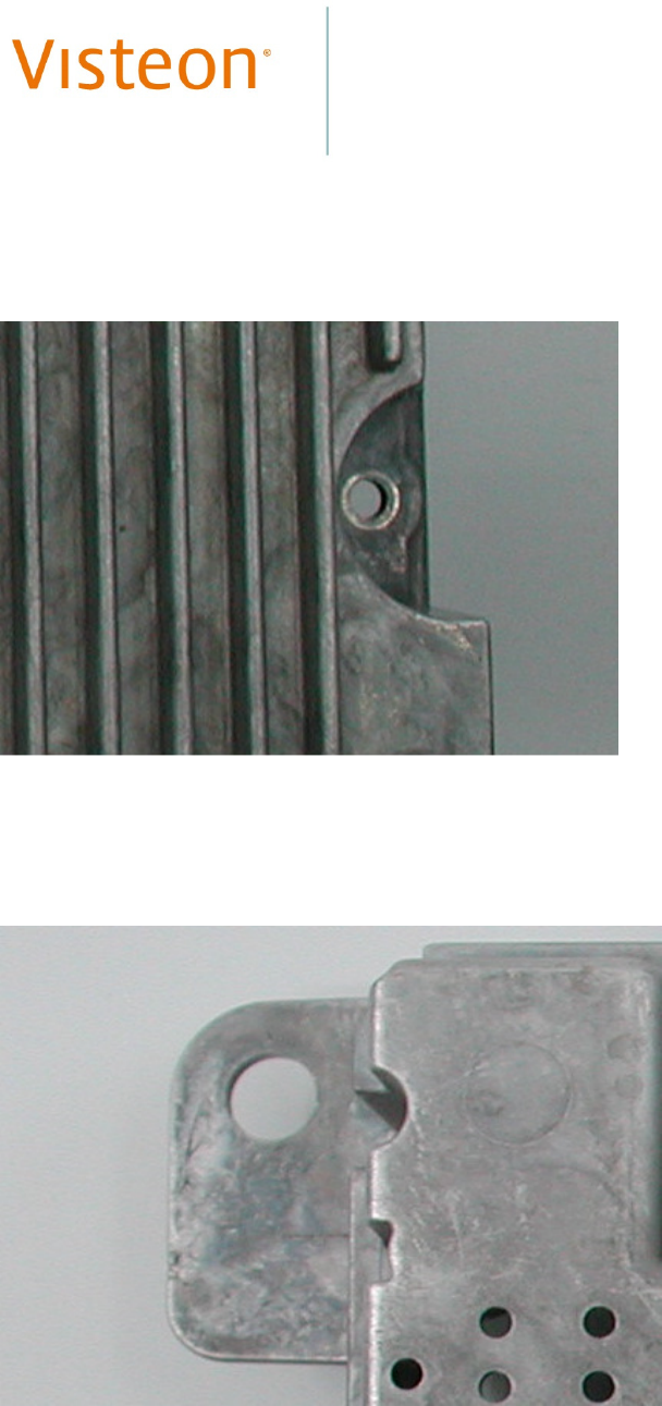
Mounting of the MFA2 Device
In the case of the mounting behind the center console, the device’s casing must be bolted to
the surface of the recessed area, using the industry-standard bolts. These bolts must pass
through the eyes and notches molded into the silver box casing for this purpose (see Figures 1
and 2 for a typical notch, eye and flange details). Use torque wrenches to ensure the correct
tightening of all bolts.
In the case of the truck variants, the specially-shaped metal retaining brackets must also be
installed, to securely bolt the silver box casing into place and to provide the required
additional resistance to vibrations. Here also, use torque wrenches to ensure the correct
tightening of all bolts.
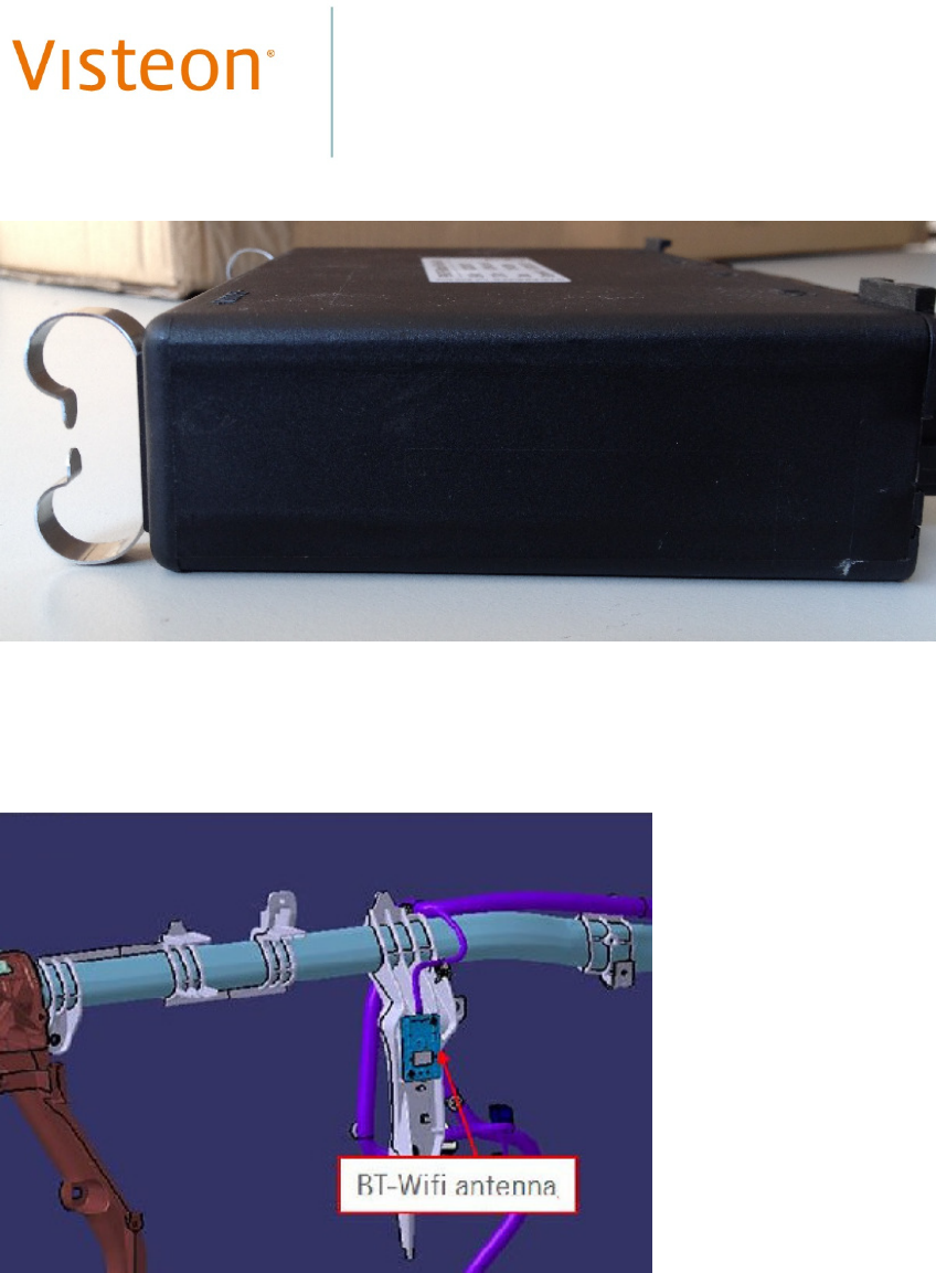
For mounting in the under-seat molded enclosure (see Figure 3), the MFA2 device is first
connected to the electrical connectors and antenna cables then pushed backwards into place.
The retaining collar is then put into place and bolted to the enclosure.
The Factory Process
Handling
• Work with clean gloves (changed on a regular basis).
• Unpack the MFA2 device as close as possible to the production line.
• Do not stack, hit or scratch in any way the unpacked MFA2 device.
• Do not push or pull on any connectors during the placement and fixing of the device.
Instead, push on the sturdy sides or edges of the casing while positioning and fixing
the device.
• Do not scratch, tear or remove the pre-fitted labels.

2
• While installing cables, make sure that no cable is pinched or damaged at any point
along its length.
• When fixed, ensure that the heat sink portion of the device’s casing is free and not
blocked by any obstruction, including by the retaining brackets, if fitted.
• If any MFA2 device is dropped or falls down, it must be scrapped.
Electrical Connections
• Check that the connectors of the vehicle are not damaged and that no connector wires
are entangled.
• After connection, ensure that all connectors are fully and properly inserted into the
corresponding connector sockets. Where connectors are supplied with retaining clips,
ensure that those connectors are securely clipped.
Antenna cables
Antenna cables of at least the prescribed minimum length of 61.0cm are to be fitted, such that
all BT/WLAN antennas are affixed on skeins or metal girders on the surfaces of the vehicle’s
bulkheads, the specific fixing mechanism is dependent on the vehicle’s model (see Figure 4
under Annexes for a typical antenna fixture).
For vans and trucks, the mountings to be used for antenna cables are on the roof of the
vehicle, whereas for cars they are on the bulkhead separating the engine area from the car’s
interior. In all cases, a separation of >20cm must be maintained between the antenna and the
occupants of the vehicle.
Connection Recommendations
• Once laid, cables must not touch any part of the MFA2 casing, including the heat sink
area.
• Once laid, cables must not hamper thermal dissipation from the MFA2 device.
• All cables must be protected against wear and tear caused by friction with any parts of
their surroundings.
3
Annexes
Figure 1: Typical Notch and Eye Construct On Silver Box Casing
Figure 2: Typical Flange and Eye Construct On Silver Box Casing
4
Figure 3: Under-Seat Enclosure For MFA2 Including Retaining Clips
Figure 4: BT/WLAN Antenna Mounted On an Iron Girder