Vita Spa Portable Users Manual Voyager 03 0509 Pdf
Portable Spa to the manual b233d3bb-6769-4e1d-9d64-d60cc5cace55
2015-02-05
: Vita-Spa Vita-Spa-Portable-Spa-Users-Manual-457251 vita-spa-portable-spa-users-manual-457251 vita-spa pdf
Open the PDF directly: View PDF ![]() .
.
Page Count: 33
“The Ultimate Portable Spa”
OWNERS
MANUAL
OWNERS
MANUAL
MIAMI FLORIDA
VOYAGER
CUSTOMER
SERVICE
877-240-9457
M-F 8 to 5 EST
VOYAGER
CUSTOMER
SERVICE
877-240-9457
M-F 8 to 5 EST
Important Operating Instructions
Please Read
Voyager Manual 03-0509 Rev.1

GENERAL INFORMATION
• Owner's Record and Service Information.............1
• Important Safety Instructions..................................2-3
• Manufacturer's Do's and Don'ts................................3
SET UP AND INSTALLATION
• Site Selection......................................................................4
• Electrical Requirements and Installation ................4
• Packing List..........................................................................4
• Part Identification Diagram...........................................5
• Assembly Instructions.................................................6-7
• Cover Installation...............................................................8
• Step Assembly Instructions ........................................9
(Optional Accessory)
OPERATION
• Connecting the Pump Suction Line......................10
• Priming the Pump.........................................................10
• Testing the GFCI .............................................................10
• Top Side Digital Control..............................................10
A. Displaying Time and Temperature...............11
B. Setting the Temperature & Time ..................11
C. Auto Heat Operation..........................................11
D. Jets Operation.......................................................11
E. Filtration Cycles......................................................12
F. Memory.....................................................................13
G. Resetting Your Spa..............................................13
• Air Control Operation...................................................12
Jet layout / use / adjustment .............................12
Jet flow control...........................................................12
• Safety Features................................................................13
A. Freeze Protection .................................................13
B. Flow Protection.....................................................13
C. Overheat Protection ...........................................13
MAINTENANCE
• Liner .....................................................................................13
• Cover ...................................................................................13
• Filter Cartridge Removal and Cleaning ................13
• Winterizing your Spa.....................................................13
• Draining and Disassembling your spa .................14
• Water Level.......................................................................14
• Important Maintenance Procedures .....................14
WATER MAINTENANCE
• Balancing the Spa Water.....................................15-16
• Water Maintenance DO's and DON'TS...............17
• Spa Water Troubleshooting................................18-19
SPA TROUBLESHOOTING
• Troubleshooting.......................................................20-22
• Service Center Information .......................................22
• Diagnostic Specification Messages........................23
SPECIFICATIONS................................................24
OPTIONAL ACCESSORIES.......................25
PACK REMOVAL INSTRUCTIONS
Instructions....................................................................26-27
Part Numbers / Diagram ..............................................28
WARRANTY...............................................................29
MAINTENANCE LOG......................................30
TABLE OF CONTENTS
PAGE 1
CAUTION
When installing the Voyager spa indoors, use care to install in areas that
can withstand exposure to water and are well ventilated.
WARNING
Findings in the “Journal of the American Medical Association” show that
women who are planning a pregnancy or are experiencing the first
months of pregnancy should avoid hot tubs and saunas. Please consult
your physician before using the Voyager spa if you are pregnant or think
you may be. For further information, see page 2 and 3.
If you have any questions regarding any of the information on the use and maintenance of your spa, please
contact DM Industries, Ltd. at (877) 240-9457 or (305) 908-8187. Mon.-Fri. 8 am-5 pm EST
Owners Record
Date Purchased: ____________________________________________________________________________
Purchased From:____________________________________________________________________________
Address:___________________________________________________________________________________
Telephone:_________________________________________________________________________________
Serial #: ___________________________________________________________________________________
Serial Number is located on lower right hand side of therapy unit
Congratulations!
Thank you for the purchase of your new Voyager spa. You are now the owner of the most portable and
comfortable spa made.
The Voyager spa has been designed to be simple to own and operate. With a little care, it will give you
many years of economical, trouble free use. This manual will guide you through the proper installation and
maintenance of your Voyager spa. Please take sufficient time to familiarize yourself with it.
We are always interested in your comments and suggestions. Please share them with us via telephone,
letter or e-mail.
Sincerely,
Eric Dormoy,
President
DM Industries, Ltd.

PAGE 2
When installing and using this electrical equipment,
basic safety precautions should always be followed,
including the following:
1. READ AND FOLLOW ALL INSTRUCTIONS.
2. WARNING - To reduce the risk of injury.
Do not permit children to use this product
unless they are closely supervised at all times.
3. A grounding wire connector is provided under
the motor unit to permit connection of a
minimum No. 8 AWG (8.4 mm) solid copper
conductor between this point and any metal
equipment, metal enclosure or electrical
equipment, metal water pipe, or conduit within
5 feet (1.5 m) of the unit.
4. DANGER - Risk of injury.
A. Replace damaged cord immediately.
B. Do not bury cord.
C. Connect to a grounded, grounding type
receptacle only.
5. WARNING - This appliance is provided with a
Ground-Fault Circuit-Interrupter (located near
the end of the power cord). The GFCI must be
tested before each use. With the plug
connected to the power outlet and with the unit
operating, push the test button. The unit should
stop operating. Push the reset button. The unit
should now operate normally. If the interrupter
fails to operate in this manner, there is ground
current flowing, indicating the possibility of an
electrical shock. Disconnect the plug from the
outlet until the fault has been identified and
corrected.
6. DANGER - Risk of Accidental Drowning.
Extreme caution must be exercised to prevent
unauthorized access by children. To avoid
accidents, ensure that children cannot use this
spa unless they are supervised at all times.
7.DANGER - Risk of injury. The filter in this spa
is sized to match the specific water flow created
by the pump. Should the need arise to replace
the filter or the pump, be sure that the flow
rates are compatible. Never operate the spa if
the filter is broken or missing. Never replace a
filter with one rated less than the flow rate on
the original filter.
8. DANGER - Risk of Electric Shock. Install at
least 5 feet (1.5 m) from all metal surfaces. A
spa may be installed within 5 feet of metal
surfaces if each metal surface is permanently
connected by a minimum No. 8 AWG (8.4)
solid copper conductor to the wire connector
under the motor unit which is provided for this
purpose.
9. DANGER - Risk of Electric Shock. Do not
permit any electric appliance, such as a light,
telephone, radio, or television, within 5 feet
(1.5 m) of a spa.
10. WARNING - To reduce the risk of injury:
A. The water in a spa should never exceed
40˚ C (104˚ F). Water temperatures
between 38˚ C (100˚ F) and 40˚ C
(104˚ F) are considered safe for a healthy
adult. Lower water temperatures are
recommended for young children and
when spa use exceeds 10 minutes.
B. Since excessive water temperatures have a
high potential for causing fetal damage
during the early months of pregnancy,
pregnant or possibly pregnant women
should limit spa water temperatures to
38˚ C (100˚ F).
C. Before entering a spa the user should
measure the water temperature with an
accurate thermometer since the tolerance
of water temperature-regulating devices
varies.
D. The use of alcohol, drugs, or medication
before or during spa use may lead to
unconsciousness with the possibility of
drowning.
E. Persons suffering from obesity or with a
medical history of heart disease, low or
high blood pressure, circulatory system
problems, or diabetes should consult a
physician before using a spa.
F.Persons using medication should consult a
physician before using a spa since some
medication may induce drowsiness while
other medication may affect heart rate,
blood pressure, and circulation.
11.WARNING - Prolonged immersion in water
that is warmer than normal body temperature
can result in a dangerous condition known as
IMPORTANT SAFETY INSTRUCTIONS
PAGE 3
HYPERTHERMIA. The causes, symptoms, and
effects of hyperthermia may be described as
follows: Hyperthermia occurs when the internal
temperature of the body reaches a level several
degrees above the normal body temperature of
98.6 degrees F. The symptoms of hyperthermia
include dizziness, fainting, drowsiness, lethargy,
and an increase in the internal temperature of
the body. The effects of hyperthermia include:
(1) unawareness of impending hazard,
(2) failure to perceive heat, (3) failure to
recognize the need to exit the spa, (4) physical
inability to exit the spa, (5) fetal damage in
pregnant women, and (6) unconsciousness
resulting in a danger of drowning.
12. WARNING
•The use of alcohol, drugs, or medication
can greatly increase the risk of fatal
hyperthermia in hot tubs and spas.
•Persons taking medications which induce
drowsiness such as tranquilizers,
antihistamines or anticoagulants should
not use the spa.
•Pregnant women and persons with a
medical history of heart disease, circulatory
problems, diabetes or high blood pressure
should consult their physician before using
the spa.
•Children are especially sensitive to hot
water. At no time should children have
unsupervised access to the spa. The use of
elevated decking may encourage children
to climb onto the thermal cover — IT IS
NOT DESIGNED AS A SAFETY OR
CHILD RESISTANT COVER! The Voyager
comes with a thermal cover which is
provided with locking straps. INSTALL the
locks for your child’s safety.
13. SAFETY SIGN
Included with this spa is a safety sign suitable
for indoor or outdoor use. The prominent
display of this sign is important to occasional
users of the spa who should be familiar with
these warnings. This sign can be easily
attached using the mounting hole in the top of
the sign. For additional copies of this sign at no
charge, contact the Voyager Service Center
at (877) 240-9457 or (305) 908-8187
Reading and understanding these warnings will
allow you to reduce the risk of causing inadvertent
damage to your spa, your surroundings, or yourself.
Read these warnings carefully.
1. DO - The water level must be 1” above all jets.
The jets can spray water out of the tub if the
water level becomes too low.
2. DO - Always unplug your motor unit before
draining and while filling.
3. DO NOT operate without the GFCI located at
the end of the power cord. This safety device
shuts off the power in a fraction of a second in
the event of an electrical short.
4. DO NOT use an extension cord to connect
the motor unit to the power source.
An extension cord will cause a voltage drop
which may cause damage to the pump motor
and controls.
5. DO - Maintain proper water pH (7.4-7.6).
The vinyl liner can be damaged by an improper
pH balance.
6. DO NOT fill the spa through any water
softening device as this could damage the liner.
7.DO- Place only on surfaces that can withstand
the floor loading requirements of your tub. If
you do not know the rating of your floor, consult
an architect or engineer before filling. See
specifications on page 22
8. DO - Install the Voyager spa only on floors or
areas that can withstand repeated exposure to
water (tile, brick, etc.).
WARNING: The use of alcohol, drugs, or
medication can greatly increase the risk of
fatal hyperthermia.
SAVE THESE INSTRUCTIONS
MANUFACTURER’S DO’S AND DON’TS
PAGE 4
SITE SELECTION
Your Voyager spa is completely self-contained.
It can be set up on a patio, deck, and indoor with
special consideration.
Structure: The Voyager spa should always be
placed on a structurally strong, relatively smooth
and level surface. Concrete, bricks, stepping stone
or treated wood deck are acceptable permanent
surfaces. See specifications on page 22 for loading
capacity.
Drainage: Do not place the Therapy module in
an area where water will "puddle" around it. A self
draining surface sloped 1 inch per 10 feet would
be ideal.
Indoor installation
Please give special consideration to the following
issues when installing your Voyager spa indoor.
1. Install your spa on water resistant, non-slip floor,
preferably with a drain to remove the water that
is splashed from the spa. Do not install on
carpet or other material that will be damaged by
moisture.
2. Take into consideration the room humidity
which will exist due to high temperatures.
Providing natural or forced ventilation in the
room will help maintain comfort and minimize
moisture damage to the surrounding environ-
ment and remove chemical odor in the air.
3. Indoor second story above finished living space
should be avoided due to the possibility of
water and humidity damage.
4. Allow full access to the spa equipment for
service.
Outdoor Installation
Please take into account the following when
considering outdoor installation.
1. Local Building Codes.
2. Provide a smooth surface (tile, concrete, wood,
brick or sand) and verify that there are no sharp
objects under the spa prior to set up.
3. Place your spa away from areas where debris
and dirt may be tracked into the spa.
4. Consider privacy, sun exposure, and wind
shielding. A sheltered environment can result in
lower operating and maintenance costs.
5. It is recommended that the spa be placed in a
location where it can be easily supervised when
in use by children.
ELECTRICAL REQUIREMENTS AND
INSTALLATION
Allow easy access to the Ground Fault Circuit
Interrupter (GFCI) which is located on the end of
the power cord. The 110 Volt GFCI and the outlet it
is plugged into should be protected from extreme
weather, landscape sprinklers and accidental spills.
A pressure clamp wire connector is provided in the
underside of the pump motor to permit connection
of a minimum No.8 AWG (8.4mm) solid copper
bonding conductor between this point and any
metal equipment, metal enclosures or electrical
equipment, metal water pipe or conduit, within 5
feet (1.5m) of the unit as needed to comply with
local requirements.
Your Voyager spa has been carefully engineered to
provide maximum safety against electrical shock.
Installation must be within 15 feet of a three wire
grounded 110V 15A outlet. The outlet should be a
minimum of 5 feet from the spa. Connecting the
Voyager spa to an improperly wired circuit, or using
an extension cord may cause damage to the
equipment that is not covered under warranty.
PACKING LIST
SET UP AND INSTALLATION
BOX TYPE QUANTITY CONTENT
KEEP THE THERAPY MODULE’S ORIGINAL
BOX. IT WILL BE NEEDED TO SHIP THE
MODULE TO A WARRANTY STATION OR THE
FACTORY IN THE UNLIKELY EVENT THE
MODULE NEEDS SERVICING.
A11 Therapy Module
1 Floor Pad
B3Each Box contains
2 Wall Sections
2 Connecting Rods
C3Each Box contains
2 Seats
D1Accessory Parts
- Subject to Change -
PAGE 5
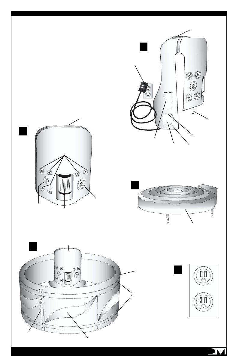
(1)
(3)
(5)
BELTS
WALL SECTIONS
INTERLOCKING
PIN
RESET
TEST
Outlet A
Outlet B
THERAPY MODULE
FILTER
GFCI
DIGITAL TOP SIDE
CONTROL PANEL
HEATER
GROUND
CLAMP
2 SPEED
PUMP
CONTROL BOX
CIRCULATION
PORT
SPA COVER
(4)
BLUE LINER
DEEP EURO CLUSTER
MASSAGE JETS
TURBO
WHIRLPOOL
JET
DIRECTIONAL DEEP
MASSAGE JET
(2)
DIGITAL TOP SIDE
CONTROL PANEL
PART IDENTIFICATION DIAGRAM
1. Therapy Module (side view)
2. Therapy Module (front view)
3. Spa
4. Spa Cover
5. Correct Outlet Types:
Outlet A—15 Amp 115 Volt
Outlet B—20 Amp 115 Volt
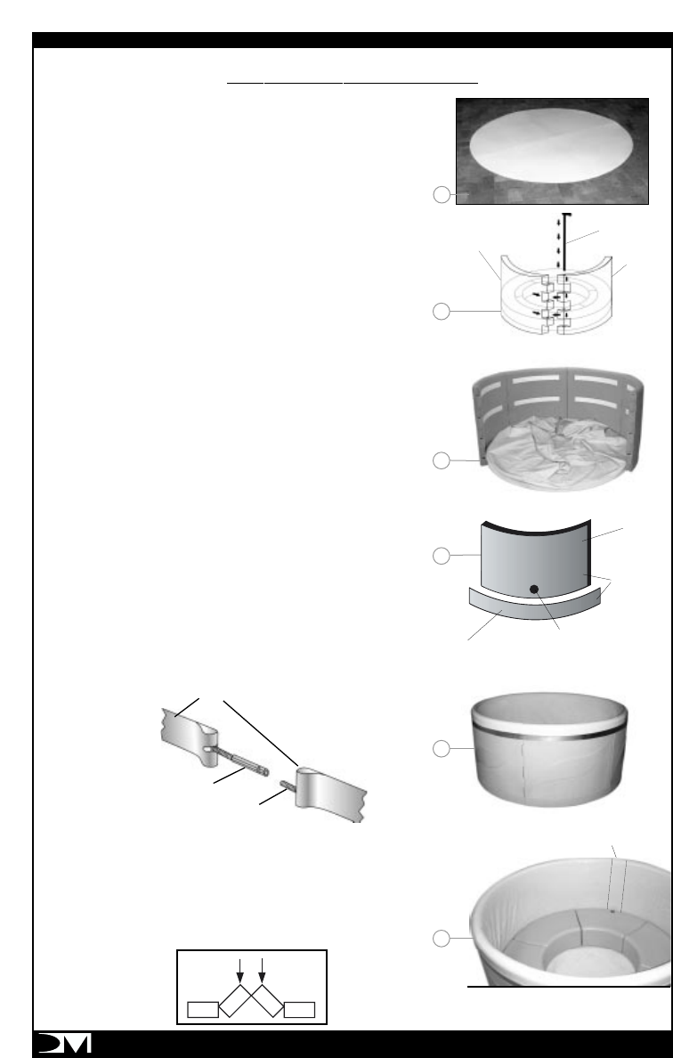
1. PLACE BOTTOM PAD on a clean, smooth, level surface.
Please see SITE SELECTION: Structure on page 4.
2. STRETCH OUT LINER. If liner is stiff, warm in the sun.
3. SET UP WALLS and install locking pins.
4. INSTALL THE LINER
a) Note that the liner has a patterned side. Place the liner so that
the patterned side faces the inside of the spa .
b) Note that the therapy module, the liner seam, the belt spindles,
and the seat with the punched hole, need to be aligned for the
therapy module to cover the seam and the belt spindles and for
the cover straps to fall in the center of the wall sections. All seats
have a knockout whole. Use a screwdriver to remove the hole
cap in the seat that will be located under the therapy module.
c) Choose location of the therapy module, taking into
consideration accessibility and electrical requirements. Refer to
SITE SELECTION on page 4.
d) Place the liner seam in the center of the wall section you would
like to put the therapy module on.
e) Stretch the liner over the top rim of the spa. Stretching the liner
into its final position will take about five minutes and may require
three or more persons.
5. INSTALL THE TOP BAND locating the belt spindle at the
liner seam. Inline with only the seat suction hole.
6. INSERT THE SEATS, aligning the seat with the punched hole
with the liner seam. To assist in the installation of the seats, it may
be necessary to position 2 seats like a pyramid (see diagram
below). Gently press down on the apex and they will all register in
place.
PAGE 6
ASSEMBLY INSTRUCTIONS
1
5
SPINDLE
BELT
BOLT
TO TIGHTEN AND TURN
USE 3/8" BOX WRENCH
3
PIN
SPA WALLS
SEAT
ASSEMBLY
4b
4a
BENCH
ALIGN
BENCH
TO WALLS
KNOCK-OUT HOLE WHERE
THERAPY MODULE SUCTION
IS TO BE INSTALLED
WALL SECTION
6
SEAM LOCATION
LOOKING DOWN
RESET
TEST
7
PAGE 7
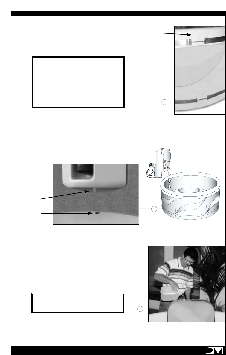
7. I NSTALL THE BOTTOM BELT aligning the belt spindle
with the top one.
8. PLACE THE THERAPY MODULE over the wall, the belt
spindles and the seat with the punched hole. When placing the
module, make sure the inside lower edges of the module are kept
away from the liner to prevent tearing it.
9. FILL UP SPA and follow the instructions listed in
“Initial Start Up Procedures.”
SEAM
PUNCHED
HOLE
INTAKE
TUBE
8
IMPORTANT: THE SPA WALLS AND
INTERLOCKING PINS HAVE NOT BEEN
DESIGNED TO SUPPORT THE WEIGHT OF THE
WATER OVER EXTENDED PERIODS OF TIME.
THE BANDS MUST BE INSTALLED TO PROVIDE
THE STRUCTURAL AND LOAD SUPPORT TO THE
SPA WALLS. FAILURE TO INSTALL THE BELTS
COULD CAUSE TEARING AT THE WALL HINGES
AND WILL VOID THE WARRANTY.
DO NOT PLUG IN THE THERAPY MODULE
UNTIL THE SPA HAS BEEN FILLED AND
PRIMED PROPERLY.
9
PAGE 8
Never cover your Voyager with a transparent
plastic covering. The UV rays from the sunlight
may cause your liner to change color and
shorten its life.
COVER INSTALLATION
1. Inflate cover with air pump provided. Do not
over inflate.
2. Place cover on filled spa. Be sure it is correctly
positioned.
3. Position the tie-down hardware on the side of
the spa so that they are easily reached by the
cover tie-down straps.
4. Allow for about a 1/2” to 3/4” slack in the tie-
down strap to make it easy to insert the strap
into hardware and to compensate for vinyl
shrinkage in cold weather.
5. Attach hardware with screws provided.
6. Keep cover fastened down at all times when
not in use. The cover locking hardware may be
locked with a key (provided).
CAUTION: FAILURE TO FOLLOW THE ABOVE
INSTRUCTIONS MAY RESULT IN INJURY OR
DROWNING. DO NOT STAND, SIT OR LIE ON OR
PERMIT ANY HEAVY WEIGHT TO REST ON THE
COVER. THE INFLATABLE COVER IS NOT A
FLOATATIO N D EVICE AN D IS MADE AS AN
INSULATING DEVICE AND SHOULD NOT BE
USED FOR ANY OTHER PURPOSE.
DOWN STRAP
LOCK
COVER
Parts Check List:
(2) Side Panels
(2) Step Treads (one curved, one straight)
(1) Strip of Foam Squares
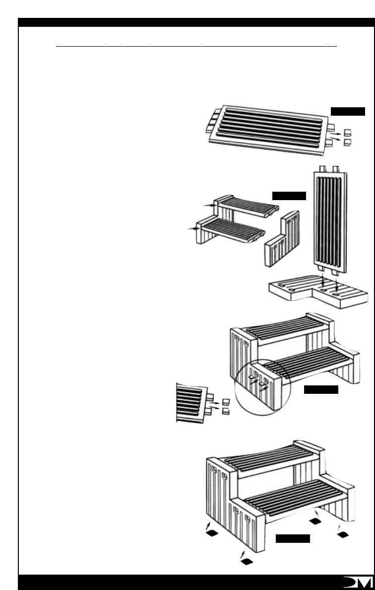
1. USING SHARP KNIFE, carefully cut the
two locking wedges off the ends of the steps and save.
(see figure 1).
2. LAY ONE OF THE SIDE PANELS
DOWN. Push the end of the step into the
openings on the side panel making sure the front
edge of the step is flush with the front edge of the
side panel. Repeat for second step. (See figure 2)
Note: top step is curved.
3. SECURE EACH STEP by tapping a locking wedge
in between the side panel and the top surface of the step. (See
figure 3).
4. PEEL OFF A FOAM SQUARE and
apply one to each of the bottom four corners to prevent
the step from slipping. (See figure 4).
PAGE 9
STEP ASSEMBLY INSTRUCTIONS (Optional Accessory)
FIGURE 1
FIGURE 2
FIGURE 3
FIGURE 4
PAGE 10
CONNECTING THE PUMP
SUCTION LINE
PRIMING THE PUMP
1. Fill the Voyager till the water is approximate-
ly 4” over the jets. Do not overfill.
2. Remove the
access door from
the module and
locate the prim-
ing hose system.
3. Remove the
valve cap.
Note: the prim-
ing valve has an
open (inline),
closed (across)
valve handle.
4. Attach by threading onto the priming valve
the male to male hose adapter.
5. Connect your garden hose to the adapter.
6. Open priming valve (inline position) and
start the water flow from your hose.
7. Plug in the voyager GFCI protected cord and
follow start up and programming directions.
8. Once the pump “starts” and you note a con-
tinuous flow of water at the jets-the Voyager
priming phase is complete.
9. Shut off water to hose.
10. Close (across position) prime valve handle.
11. Replace valve cap.
12. Store for future use the adapter.
TESTING THE GFCI
Plug in the Ground Fault Circuit Interrupter (GFCI)
into a standard 110V-15A outlet (See correct type
of outlets on page 5 ).Now is a good time to test
the GFCI. Please do so as follows:
The GFCI is a very important safety device.
The GFCI shuts off the electricity in a fraction of a
second if there is a short anywhere in the system.
The GFCI plug fits conventional 110V
outlets. It is recommended that the GFCI be
tested prior to each use. Test as follows:
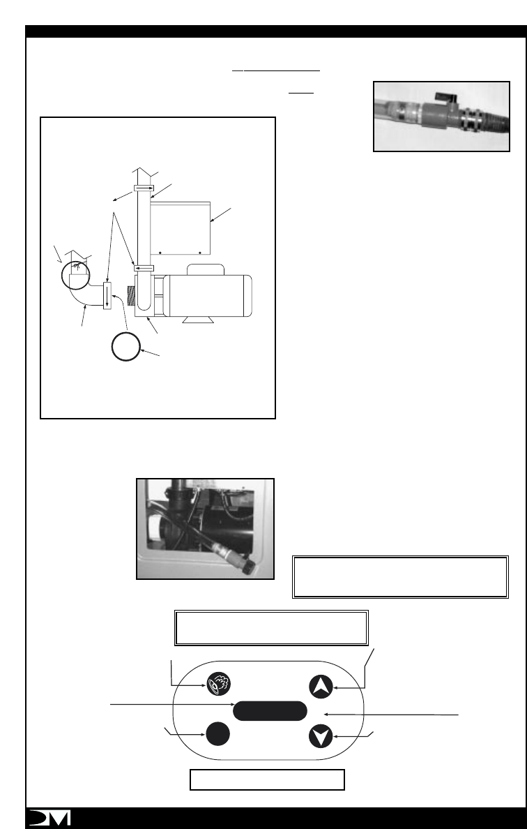
OPERATION
PROG
HEAT AM
PM
JET BUTTON:
Controls Hydro jets
• Low Speed
• High Speed
• Off
UP BUTTON
• Raises Temperature
• Forwards Time
• Reverts to Factory Defaults
(Temperature = 102°F - Time = 12PM)
If Held Down For 5 Seconds
DOWN BUTTON
• Lowers Temperature
• Sets Back Time
• Re-Boots System
If Held Down For 5 Seconds
PROGRAM "PROG" BUTTON
• Switches Display From Time
To Temperature and Vice Versa
• Initiates Temperature and Time Settings
if Held Down For 5 Seconds
LED DISPLAY
Shows Time
and Temperature
AM/PM
Indicator
TOP SIDE DIGITAL CONTROL
VOYAGER LV15 TOP SIDE CONTROL
See Next Page For Instructions
REMINDER: DO NOT USE AN EXTENSION CORD.
DOING SO MAY CAUSE DAMAGE THAT WILL
NOT BE COVERED UNDER THE WARRANTY.
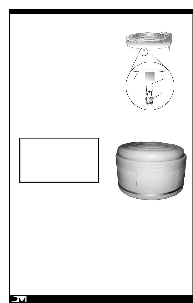
UNION
HEATER
CONTROL
PACK
MOTOR
"O"-RING TIED
TO PIPE FOR
SHIPPING ONLY
SUCTION
PIPE PUMP
"O"-RING
REMOVE O-RING TIED TO PIPE FOR SHIPPING AND INSTALL
THE "O"-RING INTO THE GROOVE ON THE UNION OF THE
SUCTION PIPE UNION. MATE THE UNION TO THE PUMP AND
ROTATE CLOCKWISE UNTIL SNUG. HAND TIGHT ONLY.
IMPORTANT
TIGHTEN UNIONS BEFORE
INSTALLING UNIT INTO SPA
PAGE 11
1. Push the TEST button on the GFCI. The
RESET button will trip out, the GFCI
indicator window will turn white and the top
side digital control LED display will go out. If
this does not happen, DO NOT USE THE
VOYAGER. CALL DM INDUSTRIES LTD'S
SERVICE CENTER FOR ASSISTANCE.
2. If the GFCI tests properly, firmly push the
RESET button back into place. The GFCI
indicator window will turn red and the top side
digital control LED display will come back on.
If this does not happen, DO NOT USE THE
VOYAGER. CALL DM INDUSTRIES LTD'S
SERVICE CENTER FOR ASSISTANCE.
3. If the GFCI trips by itself at any time, firmly
press the RESET button back into place and
perform the above tests. If this happens more
than once, DO NOT USE THE VOYAGER.
CALL DM INDUSTRIES LTD'S SERVICE
CENTER FOR ASSISTANCE.
Once the Voyager is properly powered, the digital
control will start the pump after a few seconds
and water should start flowing through the jets. If
no water is coming through, unplug the GFCI and
repeat the priming procedure or see the trouble
shooting chart on page 18.
Your Voyager spa has been designed to be simple
to operate and maintain. It is equipped with state-of-
the art digital control with LED readout (see
previous page) to show temperature and time. The
digital control has been factory programmed for
your convenience. Once properly connected, the
filtration pump and heater will automatically come
on and heat the spa to 102
A. Displaying Time or Water Temperature.
Pressing the "PROG" button will switch the
display between time and water temperature.
B. Setting Temperature and Time
1. Press and hold down the "PROG" button for 5
seconds until the display starts flashing. Note
that the display will be flashing during this
procedure.
2. Press the "UP" or "DOWN" arrow to select the
desired temperature.
3. Press the "PROG" button to show the "Hours".
4. Press the "UP" or "DOWN" arrow to select the
current hour. Note the AM and PM indicators.
5. Press the "PROG" button to show the Minutes.
6. Press the "UP" or "DOWN" arrow to select the
current minute.
7.Press "PROG" button to exit the programming
mode or wait 30 seconds for normal display to
appear
C. Auto Heat Operation.
Your spa is equipped with a 2-speed pump. The low
speed operates during filtration and heating cycles. Your
selected water temperature will be maintained
automatically 24 hours a day. The electronic thermostat
will monitor your water temperature at the top of each
hour by cycling the low speed pump for 2 minutes. If the
spa water temperature is below the set temperature, the
heater will be activated until the water temperature
reaches the set temperature, at which point both low
speed pump and heater will turn off. If the water
temperature is at the set temperature, the low speed
pump will turn off at the end of the 2 minutes..
The spa water will heat at about 2 deg F per hour. Your
selected water temperature will be maintained 24 hours
a day. The maximum temperature is set at 104° F. Note
that the heater will turn off when you are using the spa
on therapy mode (Hi-speed of the pump). The heater
only operates on low speed.
In case of an electrical power failure or if you disconnect
your spa, the selected temperature and current time will
be stored in memory. Once the power is restored, your
spa will continue to operate as per your original choice.
The time setting will obviously have to be corrected.
D. Jet Operation
The Voyager is equipped with a 2-speed
or 2-mode therapy pump. The soft-mode
(low speed) provides soft Relaxation Therapy and
the power mode (hi-speed) provides vigorous
Power Therapy.
JET Button:
1. Press "JET" to activate the Relaxation
Therapy mode. (Low speed pump).
2. Press "JET" a second time to activate the
Power Therapy mode. (High speed pump).
3. Press "JET" a third time to turn the pump off.
Note that the heater will turn off during therapy
mode (hi-speed) to allow the spa to continue to
operate on 15A 110V outlet. For safety, all jet
modes will automatically turn off after 30 minutes. If
needed, reactivate any therapy mode as indicated
above. Remember that the low-speed mode is also
controlled by the thermostat and the filtration cycle
timer. The low-speed pump will remain on if the
thermostat calls for heat or if you are operating
the spa during the auto filtration cycle (8am to
11am & 4pm to 7pm).
ALWAYS CHECK THE WATER TEMPERATURE
PRIOR TO ENTERING INTO YOUR SPA.
PAGE 12
E. Filtration Cycles
Your spa digital control has an electronic timer that
has been pre-programmed to automatically run the
filtration low speed pump 3 hours twice a day for a
total of 6 hours, from 8am to 11am, and from 4pm
to 7pm. The heater will come on as needed during
those hours. Note that filtration will also be provided
during the heating cycles, when the spa electronic
thermostat starts the low speed pump and the
heater to maintain the desired temperature.
F. Memory
The temperature setting that is entered into your spa
digital topside control are permanently retained in its
solid state memory. In the event of a power failure,
the temperature setting will be captured and held
until power returns. The temperature setting at the
time of the power failure will be restored when
power returns.
G. Resetting Your Spa
Like your PC at home, your spa electronics could get
corrupted by electrical surges or other interference
resulting in improper operations. To properly reset or
reboot your spa, unplug the GFCI and plug it back
in after 5 full minutes. Then press and hold the
“UP” arrow button for 5 seconds. The topside dis-
play will show 12:00 PM as soon as you release
the “UP” button and the temperature will be reset
to 102ºF, indicating a successful system reset.
AIRCONTROL OPERATION
AIRCONTROL OPERATION -Open to regulate
air to jets. When finished with spa, return pump
to low speed. Close so air induction does not
fight the heater.
JET LAYOUT / USE / ADJUSTMENT - All jets
have flow control “dial” adjustment. By rotating
the jet face, changing the combination of jets,
and adjusting to what extent they are open or
closed, you have the ability to “customize” each
bank of jets to your individual hydro-massage
needs of flow and pressure.
Remember, as you turn off or reduce the flow of
water out of one jet, you also increase the
pressure and flow through the others. An
important feature of this jet adjustment ability, is
to enhance specific water currents in the Voyager
Spa. For example, if you shut off one entire bank
or jet side of the module and open the other, you
can create a “true” whirlpool effect in the spa
within a few minutes.
Remember that the Voyager has a 2 speed pump.
You can further vary the massage and water
current sensations by changing speeds which
changes the amount of water flow through the
jets.
This is also true of the air control / jet relationship.
IMPORTANT: Always leave at least 2 jets on or
opened so that the pump is not back-pressured.
When finished with the use of the spa, put the
pump into low speed and close the air control.
Directional jet eyes can
be positioned as desired.
Open Closed
Directions for increasing
flow through jets.

PAGE 13
SAFETY FEATURES
A. Freeze Protection
If the temperature in the spa plumbing falls
below 50 degrees Fahrenheit (10 degrees
celsius), the water pump will turn on low speed
and run for one minute. After one minute, if the
water is still at 50 F, the heater will turn on and
raise the temperature 10 Degrees. The top side
control will display the message "ICE" to
indicate potential freeze conditions.
B. Flow Protection
If the flow of water through the heater is
insufficient, the spa controller will automatically
turn off the heater to prevent overheating. The
display will show "FLO", indicating a flow
restriction caused by a clogged filter or pump
impeller, a malfunction of the pressure switch or
a defective pump motor. Refer to the Trouble
Shooting Chart. If you cannot pinpoint the
cause, Call DM Industries Ltd's Service Center
for technical assistance.
C. Overheat Protection.
If a malfunction occurs and the spa water
temperature reaches 112F, the pump and
heater will turn off. DO NOT ENTER THE
WATER. Remove the cover and allow the
water temperature to cool down to 104 F.
Reset the system using the procedure on
page 11, section G: Resetting Your Spa.
The pump and heater will start normal opera-
tion when the water temperature reaches
104F. If this happens a second time in a row,
UNPLUG THE SPA AND CALL DM INDUS-
TRIES SERVICE CENTER FOR ASSISTANCE.
If there is an overheat condition in the spa heater,
the display will show the message "HILI". DO
NOT ENTER THE WATER. Remove the cover
and allow the water to cool down to 104F. Then
reset the system by holding down the "DOWN"
button for 5 seconds. If the "HILI" message
returns, UNPLUG THE SPA AND CALL DM
INDUSTRIES LTD'S SERVICE CENTER FOR
ASSISTANCE.
MAINTENANCE
LINER
Your spa liner will last many years when properly
used and maintained. The primary cause of failure is
the improper care of the water. A regular program of
water treatment as outlined in "Important
Maintenance Procedures" is essential. Avoid a low
pH. as this will cause unsightly wrinkles to form in
the liner.
Cleanliness - Empty your voyager and refill with
clean water every 2 to 3 months or when it becomes
cloudy and proper water chemistry does not clear it
up. While empty, use a mild non-foaming soap
solution or mild detergent to wipe away any soil or
stains on the liner. Rinse thoroughly before refilling
the spa. Do not use cleaning aids such as steel wool,
stiff bristle brushes or abrasive cleaners.
Storage - Always dry the liner if you want to move
the Voyager or store it for a period of time. It is
recommended to store the liner in a warm dry place.
Repair - If your liner gets torn or punctured, a repair
Vinyl Kit can be bought from your retailer or obtained
by calling DM Industries Ltd.'s Service Center. A
secure, unnoticeable repair can usually be made.
COVER -
Fading and discoloration will occur with
extended exposure to the sun and water chemicals.
This will not affect its integrity and its insulation value.
We recommend to clean the cover monthly to
maintain its original appearance. Just hose it down
and scrub it using a sponge with a mild soap
solution. Rinse it thoroughly and let it dry prior to
placing it back on the spa. If your cover is punctured,
repair it with the repair kit provided.
Filter Cartridge Removal and Cleaning
Clean your filter every 4 to 6 weeks depending on
usage. Turn the spa off by unplugging the GFCI and
proceed as follows:
1. Remove the filter by pulling it down.
2. Rinse the filter using a garden hose. Rotate and
separate the filter pleats while spraying water to
remove all debris possible. Let the filter dry and
then look for calcium deposits (scaling) or an oil
film. If you find these, you will need to deep clean
the filter cartridge with a filter cleaning solution to
break down and remove mineral deposits and
oils. The filter cartridge should be replaced with a
new cartridge every 6 to 9 months.
3. Place the filter cartridge back by pushing it
upward into its adapter. It is recommended to
have a second filter as spare part. Filter cartridges
and cleaning solutions are available at your
retailer.
Winterizing your Spa.
The Voyager is designed to be operated year round.
If you decide not to use your spa during the winter
or during an extended period of time, it is
recommended to disassemble it and store it in a dry
and warm place. Remember to clean and dry the
liner as outlined previously.
If you decide to keep and use your spa outside
during the winter, keep it at the desired temperature,
making sure to keep the cover on. The added
"Freeze Protection" safety feature will insure a safe
operation.
PAGE 14
Draining and Disassembling your Spa
Empty and clean your Voyager spa every 2 to 3
months. Unplug the GFCI and proceed as follows:
1. Use a hose to siphon the water or a
submersible pump. Make sure not to allow the
suction end of the hose or the submersible
pump to contact the vinyl. This may cause
damage to the liner not covered under the
warranty. Note that you can utilize one of the
jets to prime a garden hose. Place the hose in
front of a jet until the water starts coming out of
the other end. Place the hose at the bottom of
the spa and unplug the GFCI immediately.
2. Remove the Therapy Module and loosen the
lower union nut of the pump. All the water
remaining in the module will run out.
3. Disassemble the rest of the spa by reversing the
Assembly Instructions outlined on page 6.
4. Store your spa in a dry and warm place.
Water Level
Always keep the water level about 1" above the
highest jet. This will ensure that the jets will not
spray water out of the spa.
DAILY
Check water level. Keep water 1" above the highest jet.
Check and adjust chlorine level to 1.0 to 3.0 ppm if chlorine is used as
sanitizer. If Bromine is used, check weekly. Sodium dichlor is the
recommended type of sanitizer.
WEEKLY
Test the spa water using 3-way water test strips
Adjust pH and total alkalinity.PH: 7.4 to 7.6 (ideal 7.6). Total Alkalinity:
80 to 120 PPM
Maintain 1.0 to 3.0 ppm bromine or free chlorine.
Add 1 ounce of SPA DEFENDER to prevent calcium build up. Calcium
hardness: 50 to 150 ppm.
Shock treat with 2 ounces of RENEW, a non chlorine shock
MONTHLY
Inspect and clean the spa filter cartridge. It is very important to maintain
your spa filter cartridge and keep it clean and free of particles which can
restrict water flow. If the filter is not cleaned on a regular basis, the filter may
clog and restrict water flow, which causes improper filtration and poor jet
performance. See "Filter Cleaning" instructions.
Drain your spa. Follow the procedures outlined in "Draining Your Spa" page
12 and clean it following the procedures in " Cleaning The Spa Liner" page
11. When refilling your spa, be sure to follow the procedures outlined in
"Priming the Pump" page 8 and in "Balancing Your Spa Water" page 13-14.
MAINTENANCE
IMPORTANT MAINTENANCE PROCEDURES
Caution must be used with the latter
approach. In the event of electrical power
interruption, regardless of the cause, the
heater and pump will stop operating and
freeze protection will be lost,
possibly resulting in freeze damage to the
Therapy Module.
3 days a week
Four to six weeks
Two to three months
Once a week
PAGE 15
Water treatment is an important factor in the
enjoyment of your Voyager. Proper water sanitation
is essential for the health of your friends, family as
well as permitting years of trouble-free use of your
spa. The most common water chemistry problems
that can damage your spa liner are:
1. Improper pH maintenance. pH balance is critical
to proper water maintenance. Too low of a pH
level will result in excessive wrinkles and
damage of the vinyl liner as well as corrosion in
the Therapy Module.
2. Not pre-dissolving chemicals before adding to
the water.
3. Use of improper chemicals.
4. Over chlorinization. Sodium dichlor is the
recommended type of sanitizer. Sodium dichlor
dissolves easily and has a neutral pH, which
minimizes the effect that the addition of a
sanitizer has on the pH balance. Trichlor
compounds are not recommended because
they have a very low pH, are very potent and
difficult to dissolve.
BALANCING YOUR SPA WATER
The instructions below will assist you with balancing
the spa water for the first time. You will need the
following items to balance your spa water.
1. “3-WAY TEST STRIPS”
2. “PH-UP” and “PH-DOWN” for pH control.
3. “MINERAL SURFACE PROTECTOR” for Calcium
and Scale control.
4. “METAL INHIBITOR” for breakdown of mineral
deposits.
5. “POTASSIUM PEROXY MONOSULFATE” for
shock treatment.
6. “BROMINE” or CHLORINE” for sanitizing the spa
water.
Please read “WATER MAINTENANCE” then follow
these easy steps:
1. Fill your spa until the water level is 1” above the
highest jet. It is NOTadvisable to use softened
water in your spa, as it may be corrosive.
2. Add a 1/2 pint of Spa Metal Inhibitor to prevent
iron or copper deposits from staining the finish
of your spa. If your water is known to contain
high concentrations of these metals it may
be necessary to add an additional quantity of
Spa Metal Inhibitor.
3. Use a 3-Way Spa Water Test Strip or test kit to
measure the pH and Alkalinity of your water. The
following instructions utilize test strips for testing.
Immerse the test strip in the spa water, following
the instructions on the test strip container label.
Compare the test strip to the label to determine
the condition of the spa water.
4. If the Alkalinity is not within the acceptable range
(80 to 120 ppm) it should be adjusted first. If it
is low, raise the alkalinity by adding PH-UP 1 oz.
at a time, retesting until the alkalinity reaches
120 ppm. If the alkalinity is high, it should be
lowered by using PH-DOWN 1 oz. at a time.
5. After the alkalinity is properly adjusted, the pH is
next. If the pH is above 7.8, use PH-DOWN
(1 oz. at a time) to lower it to the acceptable
range. If the pH is below 7.2, add PH-UP to bring
it into the acceptable range. It is extremely
important to NEVER allow the pH of your spa
water to be under 7.0, as this can severely
damage your equipment and will void the
warranty.
6. Add Sanitizer, either chlorine or bromine. For
Chlorine: Follow the directions on the bottle.
Chlorine dissolves rapidly; you should get a
reading on the test strip within minutes of
application. For Bromine: Follow the directions
on your floating brominator. It is necessary to
add sodium bromine only when the spa is being
filled. Bromine tablets erode slowly, and it may
take several hours before you will get a reading
on the test strip. It may be necessary to adjust
the floating brominator.
7.To properly maintain the chemical balance of
your spa, follow the 3 day a week program
outlined in page 12.
WATER MAINTENANCE
BROMINE
TEST PAD
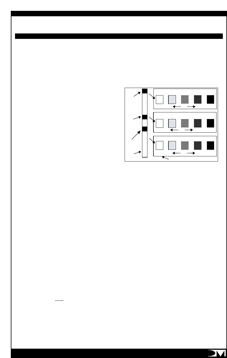
ALKALINITY
TEST PAD
pH TEST
PAD
TEST
STRIP LABEL ON TEST STRIP CONTAINER
OK
VERY LOW HIGH
HIGH
HIGH VERY HIGH
VERY LOW
VERY LOW
6.4 6.8
ppm PH (PAD NEAREST)
ppm TOTAL ALKALINITY (MIDDLE PAD)
ppm TOTAL BROMINE (END PAD)
7.2 7.6 8.4
080
120 180 240
013510
OK
OK
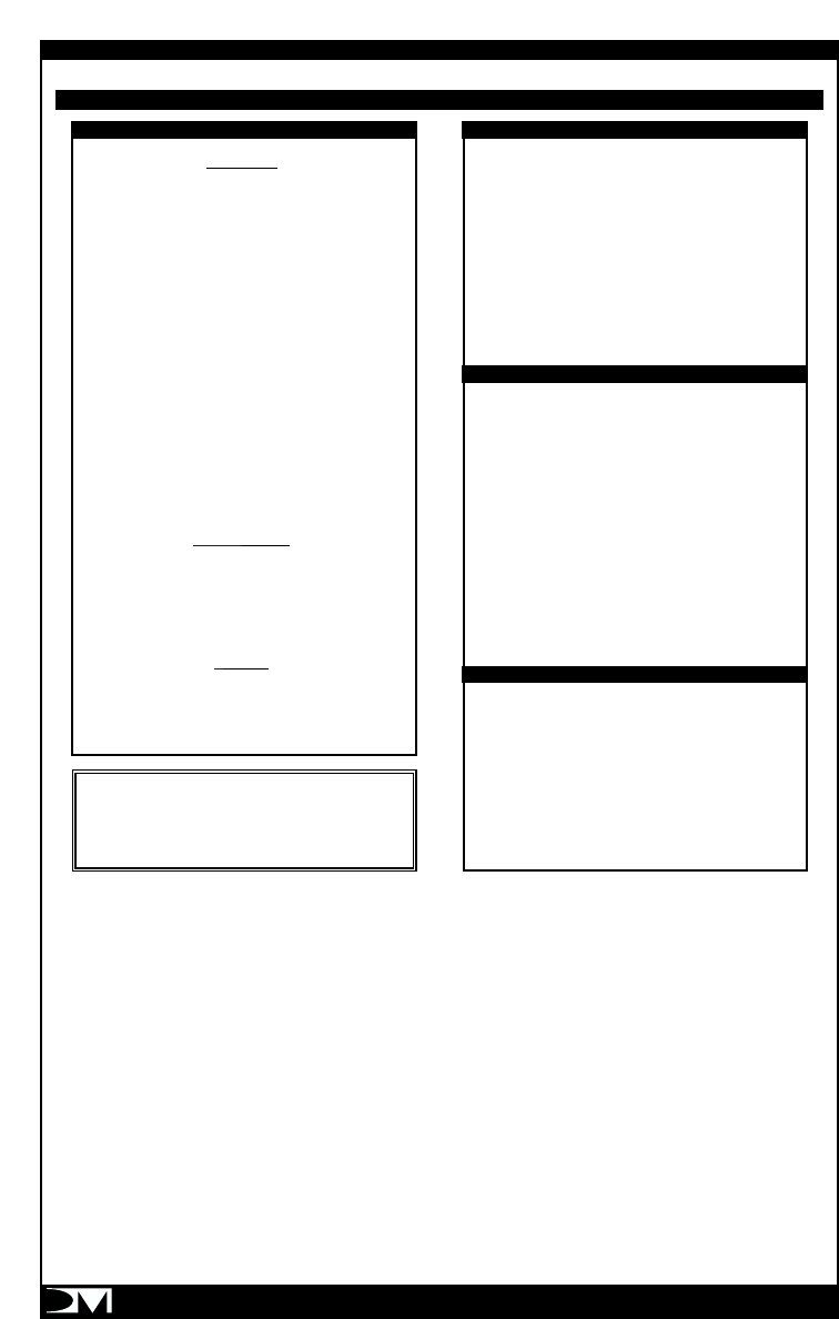
BALANCING THE SPA WATER
PAGE 16
BALANCING THE SPA WATER
3 DAY A WEEK SPA CARE PROGRAM
MONDAY
1. TEST THE WATER USING “3-WAY SPA WATER
TEST STRIPS”.
2. Adjust pH and total alkalinity - Refer to pH
and total alkalinity on label of “PH-UP” and
“PH- DOWN”.
3. Maintain 1.0 to 3.0 ppm Bromine or free
Chlorine.
4. Add 1 ounce of “METAL SURFACE
PROTECTOR” to prevent calcium build up.
5. Shock treat with 2 ounces of “POTASSIUM
PEROXY MONOSULFATE”, a non-chlorine
shock, every week as needed.
WEDNESDAY
1. Nothing required if Bromine is used as
sanitizer. Check and adjust Chlorine level if
Chlorine is used.
FRIDAY
1. Nothing required if Bromine is used as
sanitizer. Check and adjust Chlorine level if
Chlorine is used.
ALKALINITY
ADD SODIUM
BICARBONATE TO
INCREASE
IDEAL
ADD SODIUM
BISULFATE TO
DECREASE
VERY LOW
ACCEPTABLE
ZONE
HIGH
VERY HIGH
0
80
120
180
240
pH LEVEL
ADD pH DECREASER
TO LOWER pH
IDEAL
ADD pH INCREASER
TO RAISE pH
TOO ALKALINE
SCALING ZONE
COMFORT ZONE
TOO ACIDIC
CORROSIVE
ZONE
8.4
8.2
7.8
7.6
7.4
7.2
7.0
6.8
SANITIZER LEVEL
DO NOT USE SPA UNTIL TEST
KIT READING IS BELOW 5.0 ppm
RECOMMENDED LEVEL
SAFE
DO NOT USE SPA
ADD SANITIZER TO REACH
RECOMMENDED LEVEL
ppm
5.0 -
4.0 -
3.0 -
2.0 -
1.0 -
0 -
Note: The above table is an example only.
Actual spa usage will determine the amount of
chemicals required to maintain proper
chemical balance.
PAGE 17
DO Add all chemicals slowly with the hydro jets
operating in high speed.
DO Use care when handling chemicals.
DO Store granulated chlorine in a cool, dry place to
maintain the chlorine’s freshness. Granulated
chlorine will degrade if stored improperly or for a
long period of time. Do not store in sunlight.
DO Maintain total alkalinity level within the
recommended range of 80 to 120 ppm. The
calcium hardness level should be maintained in the
120 to 250 ppm range.
DO Maintain the pH level within the
recommended range of 7.4 to 7.6.
DO Maintain proper chemical balance to reduce
the risk of catching or spreading infection.
DO Use granulated chlorine/bromine produced
specifically for portable spas.
DO NOTUse swimming pool chemicals in your
spa.
DO NOTUse household bleach (liquid sodium
hypochlorine).
DO NOTUse swimming pool (muriatic) acid to
lower pH. Many swimming pool water care
products can cause damage to spa liner and
equipment.
DO NOT Allow anyone to be in the spa while
chemicals are being added or dissolving.
DO NOT Use incorrect products such as Trichlor,
which has a very low pH (2.6), dissolves very
slowly, is highly concentrated, and was designed for
concrete or plaster swimming pools. It will cause
damage to your spa!
CHEMICAL SAFETY INSTRUCTIONS
When using chemicals, read labels carefully and
follow directions precisely. Though chemicals
protect you and your spa when used correctly, they
may be hazardous in a concentrated form. Observe
these guidelines:
DO Accurately measure and use the exact
quantities specified, never more.
DO Handle all containers with care. Store in a cool,
dry, well ventilated place.
DO Keep chemical containers closed at all times
when not in use. Replace caps on proper
containers.
DO Allow only a responsible person to handle spa
chemicals. Keep them out of the reach of children.
DO Follow the emergency advice on the product
label in case of accidental contact, or if the chemical
is swallowed. Call a doctor or local Poison Control
Center. If a doctor is needed, take the product
container along so that the substance can be
identified.
DO NOT inhale fumes or let chemicals come in
contact with your eyes, nose or mouth. Wash your
hands after use.
DO NOT Let chemicals get on surrounding
surfaces or landscaping. Don’t use a vacuum
cleaner to clean up chemical spills.
DO NOT Smoke around chemicals. Fumes may be
highly flammable.
WATER MAINTENANCE DO’S AND DON’TS
DO NOT USE HYDROGEN PEROXIDE
OR HYDROCHLORIDE BASE CHEMICALS.

PAGE 18
SPA WATER TROUBLESHOOTING
SYMPTOM PROBABLE CAUSE SOLUTIONS
Cloudy Water Inadequate filtration/dirty filter Clean filter with a filter cleaner or degreaser.
Excessive oils/organic matter Shock the spa with “POTASSIUM PEROXY
MONOSULFATE”.
Improper sanitation Increase sanitizer to recommended level.
High pH and/or high alkalinity Adjust pH; add “PH-DOWN”.
Suspended particles/organic matter Use clarifier.
Overused or old water Drain the spa, clean and refill.
Water Odor Excessive organics Shock the spa with “POTASSIUM PEROXY
/too many chloramines/ MONOSULFATE”
bromamines - insufficient free
available chlorine
Improper sanitation Increase sanitizer level to
recommended level.
Low pH Raise pH with “PH-UP”.
Chlorine Odor Too many chloramines-insufficient Shock the spa with “POTASSIUM PEROXY
free available chlorine MONOSULFATE”
Low pH Adjust pH; raise pH with “PH-UP”
Musty Odor Bacterial or algae growth Shock the spa. If problem is visible,
draining and cleaning may be required.
Foaming Buildup of body oils, Add defoamer; or drain and refill.
lotion and chemicals
resulting in soap or detergent
Overused or old water Drain and refill.
Excessive organics Shock with “POTASSIUM PEROXY
MONOSULFATE”.
Organic Buildup/ Body oils and dirtWipe off scum with a clean rag or use mild
Scum Ring detergent. If needed, drain, refill spa, and
Around The Tub adjust water.
Inadequate filtration Clean filter with a filter cleaner or degreaser.

PAGE 19
SYMPTOMPROBABLE CAUSE SOLUTIONS
Algae High pH Shock with “POTASSIUM PEROXY
MONOSULFATE”; adjust pH.
Low free chlorine/bromine Shock with “POTASSIUM PEROXY
MONOSULFATE”; maintain sanitizer at
recommended level
Eye Irritation Low pH Raise pH with “PH-UP”.
Insufficient free available Shock with “POTASSIUM PEROXY
chlorine/bromine MONOSULFATE”.
Skin Irritation/Rash Unsanitary/polluted water Maintain recommended sanitizer residual at
all times; super-chlorinate.
Chlorine/bromine level too high Allow chlorine/bromine level to drop below
(above 5ppm FAC) 5 ppm before using spa.
Stains pH or total alkalinity too low Adjust pH and total alkalinity; use
sequestering agent; drain and clean with
appropriate product.
High iron or copper in water source Use sequestering agent for metals;
adjust water
Scale Too much calcium dissolved Adjust total alkalinity and pH levels by
in water-pH adding the appropriate sodium bisulfate
product; with concentrated scale deposits,
drain the spa, clean the liner as outlined in
Liner Clean Up), refill the spa and balance
the water.

PAGE 20
I. RESETTING YOUR SPA
The first step to take to troubleshoot your spa is
to reboot its electronic system. Like your PC at
home, your spa electronics could get corrupted
by electrical surges or other interference resulting
in improper operations. Before you call for
service, please reset or reboot your spa to see if
the malfunction disappears. To properly reset
your spa, unplug the GFCI and plug it back after
5 full minutes. Then press and hold down the
“UP” arrow button for 5 seconds. The topside
display will show 12:00PM as soon as you
release the “UP” button, the temperature will be
reset to 102ºF, indicating a successful system
reset.
II. PUMP WILL NOT OPERATE AND TOP
SIDE L.E.D. DISPLAY IS OFF
Cause:
There is no power to the spa.
Solution:
Check GFCI as outlined in "Testing GFCI"
page 8.
1. If the GFCI tests properly, call the Service
Center for assistance and mention code
"GFCI-1".
2. If the GFCI is inoperative, unplug the
GFCI and test the electrical outlet using a
110v appliance such as a lamp or hair
dryer.
a. If the appliance does not operate, your
main panel circuit breaker has tripped.
Reset it.
Note: If your breaker trips frequently,
make sure your spa is not connected to
an extension cord or that the electrical
circuit your outlet is on does not have a
major appliance connected to it. Poor
household wiring and/or bad connection
can cause low voltage and trip your circuit
breaker. Make sure you have at least
110V at the outlet when the spa operate
with the heater on. You might have to
move your spa to connect it to a different
outlet or ask a licensed electrician to run
a dedicated circuit for it.
We suggest you spray the equipment
system once every 2 months with WD-
40, a silicone spray that is very helpful in
protecting the equipment and electrical
box from rust and moisture intrusion.
b. If the appliance operates, the GFCI
is defective. DO NOT USE YOUR SPA.
Call the Service Center for assistance and
mention the code "GFCI-2".
III. PUMP WILL NOT OPERATE AND TOP
SIDE L.E.D. DISPLAY IS ON
Cause:
Your system software could have been corrupted
by electrical noise, spike or interference.
Solution:
Unplug the GFCI and plug it back in after 3-5 full
minutes. Then press and hold down the "UP"
arrow button for 5 seconds to reboot the system.
The topside display will show 12:00PM as soon
as you release the "UP" button. The temperature
will be reset to 102F.
If the pump operates properly, set your desired
water temperature and current time as outline in
"Setting Time and Temperature" on page 8-9. If
the pump does not operate and the topside is
operative (pressing "PROG" button will switch
time and temperature back and forth), the pump
could have overheated and shut down. Wait a
couple of hours for it to cool down. If the pump
does not become operative within 4 hours, call
the Service Center for assistance and mention
the code "PUMP-1".
IV. GFCI TRIPS WHEN TRYING TO OPERATE
THE SPA DO NOT USE THE SPA.
Call Service Center for assistance and mention
code "GFCI-0"
TROUBLESHOOTING

PAGE 21
V.SPA WILL NOT HEAT TO DESIRED
TEMPERATURE
NOTE that the pump needs to be operating
on LOW SPEED for the heater to come on. If
the pump does not operate, refer to items I
and II.
1. Pump operates on low speed and there
are no diagnostic messages shown on
the display.
Cause:
Temperature is set too low
Solution:
Set the temperature higher. The spa water
temperature will rise about 2 degree F.
per hour depending on the season and if it is
indoor or outdoor. Allow enough time for the spa
to reach the desired temperature. Maximum
allowed temperature is 104F.
Cause:
Spa cover is improperly positioned.
Solution:
Your spa needs to be covered properly if it is to
heat properly, especially outdoors in cold climate.
Cause:
Filter cartridge could be dirty and restricting the
water flow intermittently. The diagnostic message
"FLO" will appear when this happens but you
might not see it because it is intermittent.
Solution:
Remove the filter cartridge and clean as
outlined in "Filter Cartridge Removal and
Clean Up" page 13. If this does not solve the
situation, call Service Center for assistance
and mention the code "LOW HEAT-1"
2. Pump operates on low speed and there
is a "FLO" diagnostic message: "FLO"
indicates a low water flow or pressure
condition resulting from an obstruction in
the plumbing. Note that the heater is
disabled for safety during that condition.
Cause:
Obstruction in the plumbing.
Solution:
a. Remove the filter cartridge and clean it.
See instruction on page 11 If the
condition persists, there could be an
obstruction in the impeller of the
pump. This condition could happen
if the spa is operated without a filter
cartridge. It is important to follow
the "Filter Cartridge Removal and
Cleaning" instruction of turning the
spa off when removing the filter.
Objects up to 1-1/2" in size could be
sucked through and obstruct the line
or pump impeller.
b. Unplug the therapy module, lift it from
the spa and inspect the plumbing by
opening the unions for blocking
materials such as hair, leaves, string,
plastic bags, etc.
c. If no blocking objects were found
and the FLO message still shows,
there could be a defective or
out-of-calibration pressure switch.
Call Service Center for assistance and
mention the code "FLO-1"
3. Pump low or high speeds do not
operate and there is a "FLO" message.
Call Service center for assistance and
mention the code "FLO-2".
4. Pump operates on low speed and there
is a "LS=0, LS=S, SS=0 or SS=S"
diagnostic message. This indicates a
non-functional water or High Limit
temperature sensor. Call the Service
Center for assistance and mention the
code indicated.
VI. NO WATER FLOW AT JETS AND THE
PUMP IS OPERATING.
Cause:
Loss of prime in the module
Solution:
Prime module by following Priming Instruction on
page 10. (Check the pump unions to make sure
they are not loose.) If this does not solve the
problem, call Service Center for assistance and
mention code "NO FLOW-1"

VII. LACK OF PRESSURE AT ONE OR
SEVERAL OF THE JETS
Cause:
Jet(s) could be closed.
Solution:
Open jet(s). The flow of the jets is controlled by
the jet finger ring. Adjust the ring to direct the
water to the desired jets. See instructions on
page 12.
Cause:
Obstruction in plumbing.
Solution:
Remove the jet face(s), clean and
re-install. See section on HYDROTHERAPY JETS.
If any of the above does not solve the
problem, (page 12) call Service Center and
mention code "LOW FLOW-1"
IX. THERAPY MODULE LEAKS
Cause:
Loose union(s) at the pump.
Solution:
Unplug the module. Remove door to the unions.
Hand tighten. Do not use pliers. If the leak is
anywhere else, call Service Center for assistance.
X. WATER LEAK THROUGH THE LINER
Cause:
Puncture of the liner.
Solution:
Patch the hole using a vinyl patch kit. A vinyl
patch kit can be obtain at your retailer or by call-
ing the Service Center. In the unlikely event that
the leak is at the seam, call the Service Center to
order your replacement liner.
XI. WATER NOT CLEAR
Cause:
Dirty filter cartridge.
Solution:
Clean or replace the cartridge.
Cause:
Improper water chemistry.
Solution:
See "Balancing your spa water" and "Water
Maintenance" sections on page 13-15.
Cause:
High content of solid in water.
Solution:
Use clarifier or drain and refill the spa.
SERVICE CENTER
Your Voyager Therapy Module has been
designed to minimize service requirements.
There are no user serviceable parts in the
module.
9am - 5pm Mon.-Fri. EST
Toll Free: (877) 240-9457
or (305) 908-8187
Fax: (305) 685-9794
e-mail:
voyager@dmindustries.com
Attn: Voyager Service Center
PAGE 22
Do not try to service the module or the GFCI.
If you have an operation problem, go carefully
through the troubleshooting steps outlined in
the troubleshooting section of this manual. If
you cannot correct the problem, contact DM
Industries Ltd.'s Service Center for assistance
or for the nearest Service Center to you.

PAGE 23
FLO Flow Protection - If the flow of water through the heater is insufficient, the spa controller
will automatically turn off the heater to prevent overheating. The display will show
"FLO", indicating a flow restriction caused by a clogged filter or pump impeller, a malfunction
of in the pressure switch or a defective pump motor. Refer to the Trouble Shooting Chart.
If you cannot pinpoint the cause, Call the Service Center for assistance.
HILIOverheat Protection - If a malfunction occurs and the spa water temperature reaches
112F, the pump and heater will turn off. DO NOT ENTER THE WATER. Remove the cover
and allow the water temperature to cool down to 104 F. The pump and heater will start
normal operation when the water temperature reaches 104F. If his happens a second time
in a row, UNPLUG THE SPA AND CALL THE SERVICE CENTER FOR ASSISTANCE.
If there is an overheat condition in the spa heater (118F), the display will show the message
"HILI". DO NOT ENTER THE WATER. Remove the cover and allow the water to cool down
to 104F. Then reset the system by holding down the "DOWN" button for 5 seconds.
If the "HILI" message returns, UNPLUG THE SPA AND CALL THE SERVICE CENTER
FOR ASSISTANCE.
ICE Freeze Protection - If the temperature in the spa plumbing falls below 50 degrees
Fahrenheit (10 degrees Celsius), the topside will display the message "ICE" to indicate
potential freeze conditions. The water pump will turn on low speed and run for one minute.
After one minute, if the water is still at 50 F, the heater will turn on and raise the temperature
10 degrees. The topside control will display the message "ICE" to indicate potential
freeze conditions.
LS=0 Open Sensor - The water temperature sensor is non-functional. Call the Service Center for
assistance and mention the displayed code.
SS=0, Open Sensor - The High Limit temperature sensor is non-functional.
SS=S Call the Service Center for assistance and mention the displayed code.
DIAGNOSTIC MESSAGES
LS=S

PAGE 24
Capacity
Seating 4-6 Adults
Water (average fill) 400 Gallons
Spa
Outside Dimensions 72 inches
Inside Dimensions 66 inches
Overall Height 34 inches
Water Depth (average fill) 28 inches
Therapy Module
Number of Jets 8
Directional 2
Turbo Whirlpool 1
Pump Single phase,
110V/60HZ 2 speed
Heater 1.5kw 110V
Digital Control LV15 – 12V
Filter 25 sq. ft. Remay Polyester
Module Rating 110V 15A
Weights
Spa complete dry 280 lbs
1 each, Box A: Therapy Unit 76 lbs
3 each, Boxes B: Wall (2 walls/box) 40 lbs each box
3 each, Boxes C: Seat (2 seats/box) 21 lbs each box
1 Box accessory parts:
Liner-Bands-Warranty instructions 36 lbs.
Spa with water at 28" * Approx. 3600 lbs * *
Spa with water at 34" * * * Approx. 4300 lbs. * *
Dead Weight Floor Loading
With water at 28" 150 lbs per square foot
With water at 34" 180 lbs per square foot
* Minimal utilization height - 1” above highest Jet.
* * Weight of users not included
* * * Maximum water height
All sizes are approximate. Specifications subject to change without notice.
SPECIFICATIONS
PAGE 25
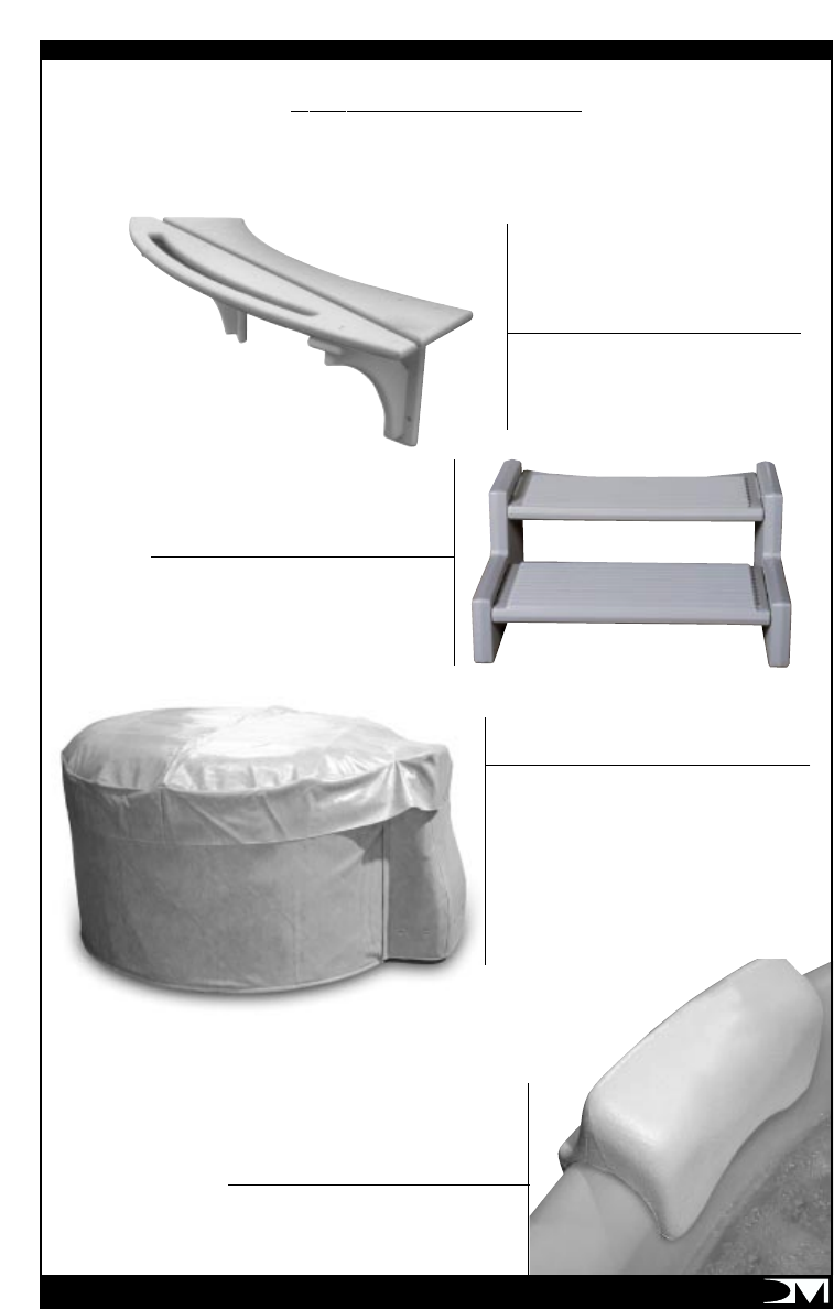
OPTIONAL ACCESSORIES
REPOSITIONAL HEADREST
STEPS
COLD WEATHER INSULATING
SYSTEM
To purchase these optional accessories, contact your local dealer or call DM Industries, Ltd.’s
Service Center at 305.908.8187 or Toll Free 877.240.9457. Fax us at 305.685.9794 or
E-mail us at voyager@dmindustries.com.
Made of wood for strength.
Easily attaches to spa wall.
Two slip resistant treads for
easy entry. Made of the same
material as your Voyager Spa.
SHELF & TOWEL RACK
Four piece “blanket” sections easily installs with
Velcro, completely enclosing the spa. Outer jacket
is an attractive grey marine naugahyde that
matches the Voyager. This is sewn to Reflective ®,
the same five-layer space age material used in
survival blankets and sunshades. Controls 97% of
radiant heat loss and also serves as an additional
thermal barrier.
For extra head and neck
support.
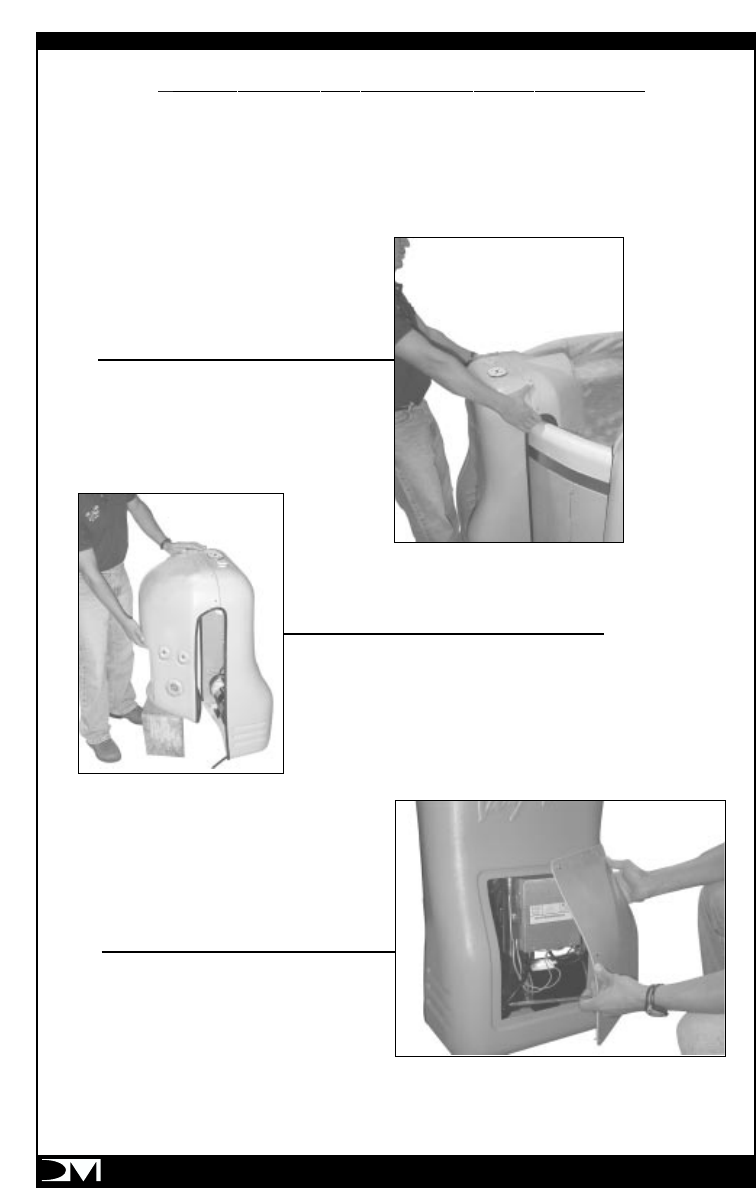
VOYAGER PACK REMOVAL INSTRUCTIONS:
If at anytime during the life of your Voyager unit, it is found necessary to repair the control sys-
tem, by following the steps below, the system can easily be removed and brought to a service
center.
1. Disconnect power to spa by unplugging the unit.
2. Lift the therapy unit from out of the spa.
3. Set the therapy unit down on a level surface.
4. Open the small access door to view the
control box.
PAGE 26
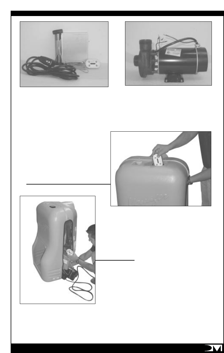
FIG. A FIG. B
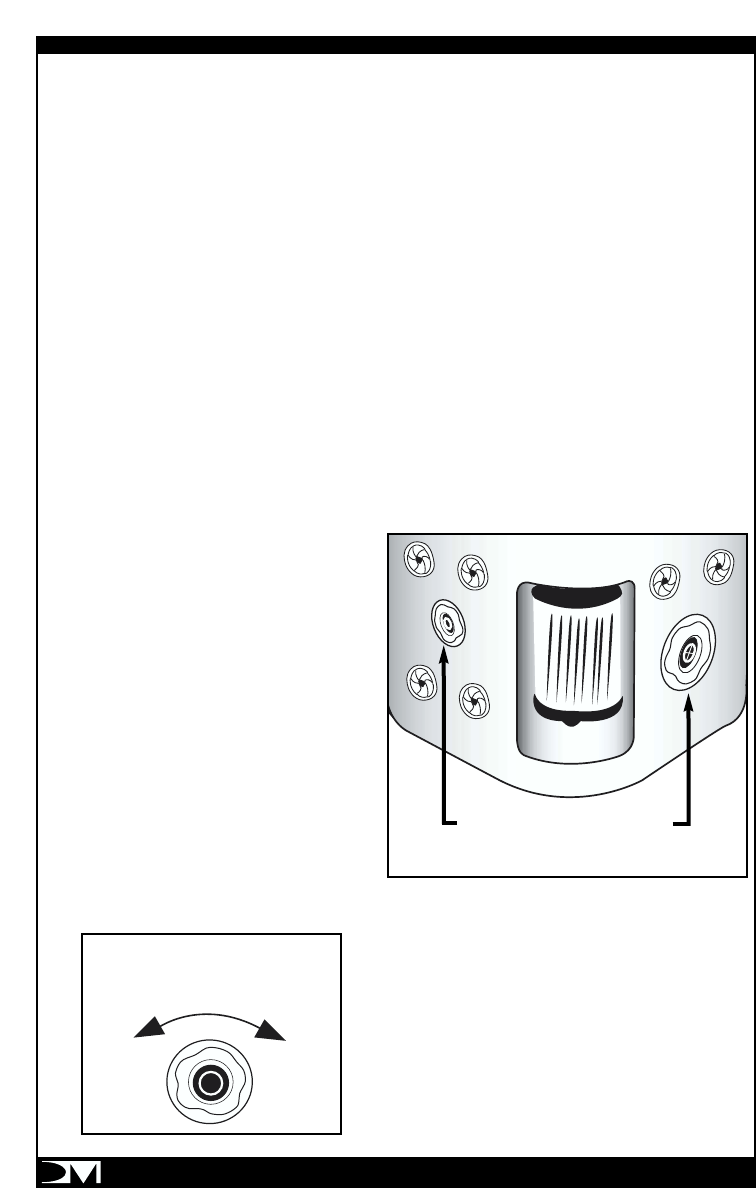
5. Three different assemblies can be removed for service.
a. The control system including the control panel. (FIG. A)
b. The pump assembly. ( FIG B )
c. The entire equipment assembly (Control System and Pump Assembly)
6.REMOVAL OF THE CONTROL SYSTEM
a. Lift the topside control pad from the
cowling by prying it up and feed through
the opening under it into the therapy
module.
b. Disconnect the pump power supply cord
from the metal control box.
c. Reach through the access door and
loosen the 2 heater nuts (1 & 2 FIG. A)
7. Reach through the side of the therapy unit and lift
and remove the control system with the control panel
and power cord.
8. Package the equipment so that no damage may be done to the control pad wiring or the
sensors attached to the heater assembly. Leave the GFCI power cord attached to the
equipment and carefully coil it so that no damage may occur during shipping.
9. When the equipment is returned, replace it by reversing the order of removal.
PAGE 27
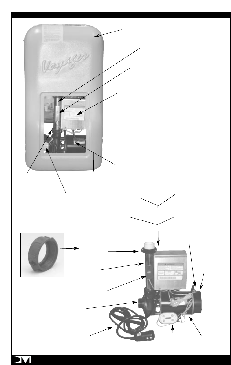
Therapy Module
615100
Pack
469583
Water Temp Sensor
Part No. LX-LW500
Motor
422102
Box Only
467587
Box/Heater
468596
Box/Heater
468596
Circuit Board
451104
Heater
411093
Heater Sensor
451126
Pump / Motor
420431
Wet End
423013
Wet End
423013
Power Cord
460904
Split Nut (2)
411054
Split Nut (2)
411054
Heater
411093
Heater Sensor
451126
Pack Complete
469583
Box Only
467587
Water Sensor
Part No. LX-LW500
Spa Side
451105
Motor
422102
Pump / Motor
420431
PAGE 28

DM Industries Ltd warrants the VOYAGER SPA to
be free of defects in material and workmanship
from the periods indicated below from the date of
purchase.
Component Warranted for
Wall Sections ..............3 Years
Seats.....................3 Years
Vinyl Liner ................3 Years
Therapy Module ...........1 Year
Cover ....................1 Year
Extent of Warranty:
This warranty extends only to the original
purchaser of the Voyager and terminates upon
transfer of ownership. The warranty does not
extend to commercial, institutional or rental use or
installation. The warranty applies only to Voyagers
installed within the United States. This warranty is
an "Over-the-Counter" replacement warranty. All
freight charges are the responsibility of the
purchaser. All warranted repairs will be performed
at no charge during the warranty periods.
Components requiring servicing under this
warranty will be repaired or replaced at
DM Industries Ltd’s sole discretion. Repair work
done by DM Industries Ltd or its Authorized
Service Centers is guaranteed for 90 days or
for the remainder of the warranty period, which
ever is longer.
Warranty Process:
All warranty inquiries should be addressed to DM
Industries Ltd ‘s Service Center at toll free number
(M-F, 8:30am to 5pm EST) or by Fax at (305)
685-9794 or by E-mail at dmindustries.com Attn:
Voyager Service Center or in writing to 2320 NW
147 Street, Miami, FL 33054. An RGA
(Return Good Authorization) number will be
issued and components requiring services shall
be returned to DM Industries Ltd. or its Authorized
Service Center, freight prepaid.
Exclusion:
This warranty is void if DM Industries Ltd
determines that the spa has been subjected to
any alterations or repairs by anyone other than an
authorized service center, or that the spa has
been subjected to misuses, negligence, improper
installation or operations other than in accordance
with the instructions in the owner’s manual,
including but not limited to damage to
components caused by improper pH balance or
other improper water chemistry maintenance, or
by failure to maintain and clean the filtration
systems;damage to the components or the vinyl
liner caused by operating the spa without water
or at the improper water level, filling or operating
the spa with water at temperature below 40 deg
F or above 104º F, using an extension cord, or
allowing undissolved or concentrated chemicals
to lie on the vinyl surface, or leaving the spa
empty in direct sunlight
Disclaimer.
Except as expressly provided, there shall be no
other warranty or obligation, expressed or implied,
oral or statutory. No retailer or other person has
the authority to make any warranties or
representations covering DM Industries Ltd or its
products. DM Industries Ltd and its
representatives shall not be liable for any injury,
loss, cost or other damage, including but not
limited to, loss of use, inconvenience, cost of
removal of a permanent installation, or any other
incidental or consequential costs, expenses, or
damages. Under no circumstances shall DM
Industries Ltd or any of its representatives be held
liable for injury to any persons or damage to
property, however arising. Some states do not
allow exclusions or limitations of incidental or
consequential damages, so the aforementioned
limitations or exclusions may not apply to you.
This warranty gives us specific legal rights, and you
may also have other rights that vary from state to
state. All specifications are subject to change
without notice.
LIMITED REPLACEMENT WARRANTY
DM Industries Ltd.'s Service Center
Toll Free at: (877) 240-9457 or (305) 908-8187
Fax: (305) 685-9794
or e-mail us at: voyager@dmindustries.com
Attn: Voyager Service Center

Maintenance Log
PAGE 30
_____________________________________________________
_____________________________________________________
_____________________________________________________
_____________________________________________________
_____________________________________________________
_____________________________________________________
_____________________________________________________
_____________________________________________________
_____________________________________________________
_____________________________________________________
_____________________________________________________
_____________________________________________________
_____________________________________________________
_____________________________________________________
_____________________________________________________
_____________________________________________________
_____________________________________________________
_____________________________________________________
_____________________________________________________
_____________________________________________________
_____________________________________________________
_____________________________________________________
Use this page to keep a record of when you perform any maintenance on your spa.

© 2003 DM Industries, Ltd., 2320 Northwest 147th Street, Miami, Florida 33054
VOY03-0509
DM Industries Ltd.'s Service Center
Toll Free at
(877) 240-9457
or
(305) 908-8187
Fax:
(305) 685-9794
or e-mail us at
voyager@dmindustries.com
Attn:
Voyager Service Center
