Vitec Group Communications CEL-BP VITEC CellCom 10 Digital Wireless Intercom User Manual
Vitec Group Communications Limited VITEC CellCom 10 Digital Wireless Intercom
UserManual.wiki
>
Vitec Group Communications
>
CEL BP User Manual
User manual
Navigation menu
Upload a User Manual
Namespaces
Wiki Guide
HTML
PDF
Info
Views
User Manual
Discussion / Help
Navigation

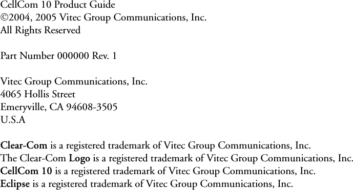
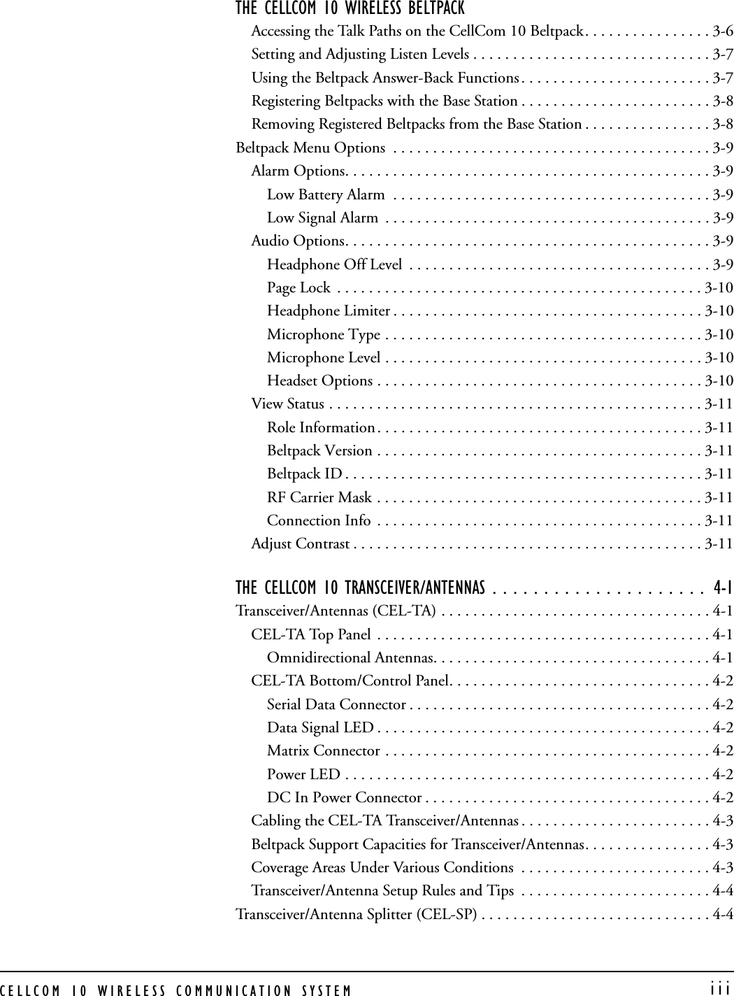


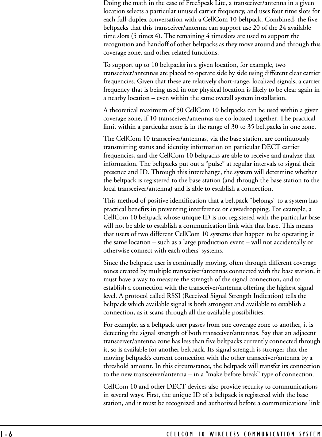


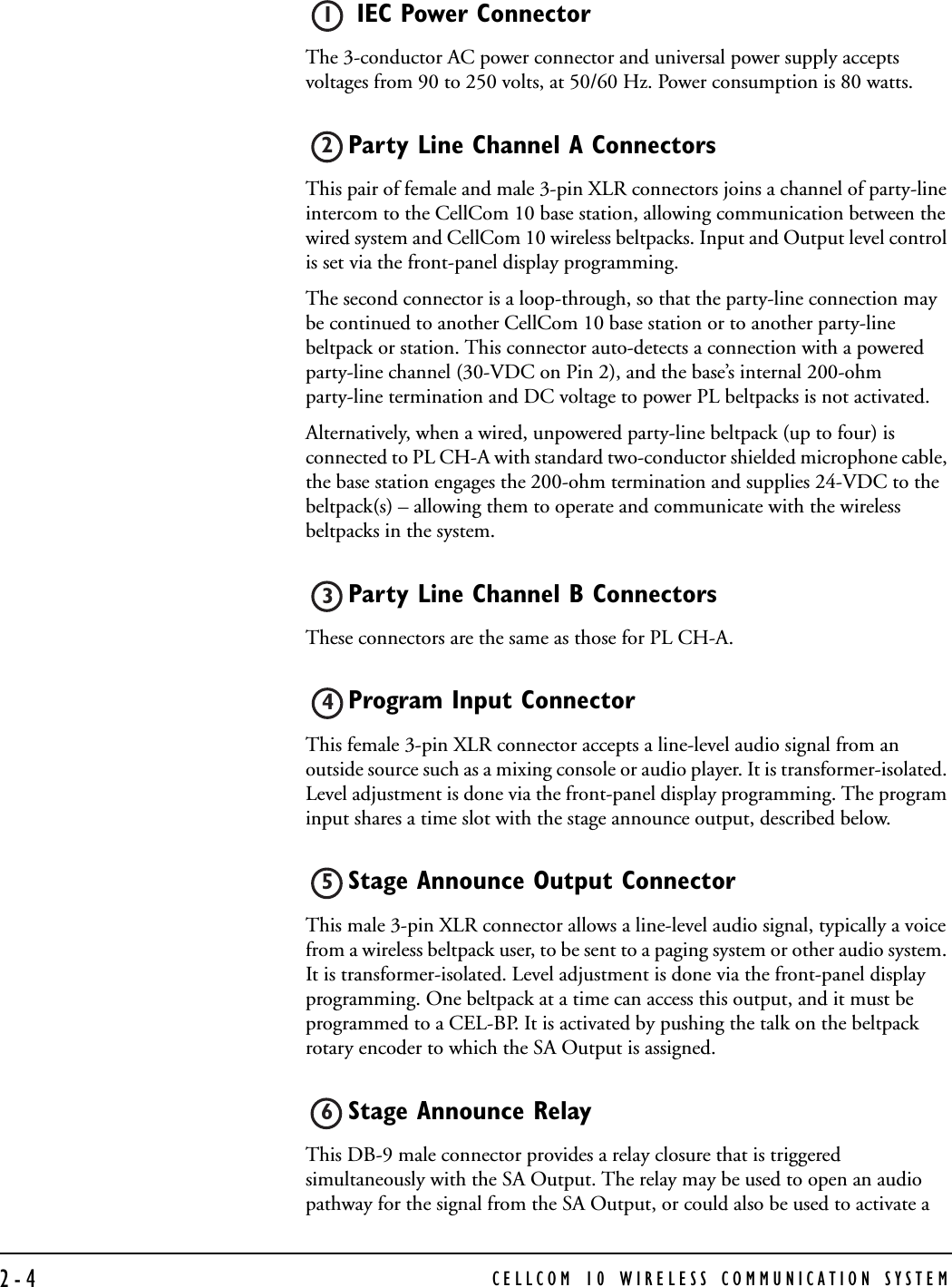
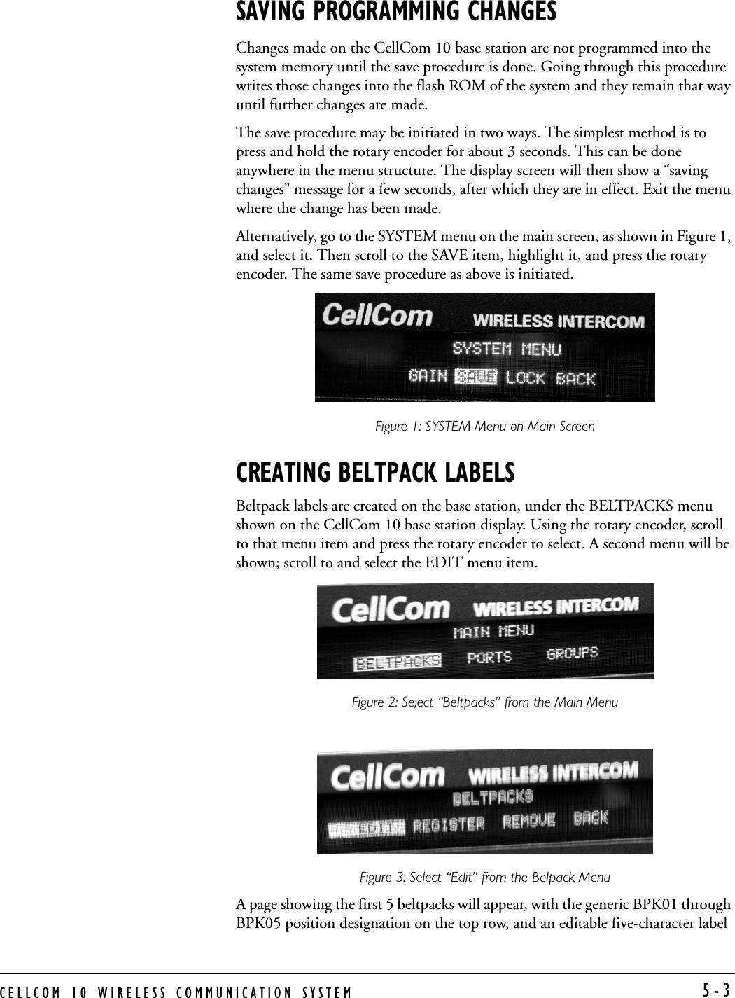
![CELLCOM 10 WIRELESS COMMUNICATION SYSTEM 2-3Display Screen The display screen shows all of the menus and programming options that are available within the CellCom 10 system. The user can select a particular beltpack and view all of its current talk/listen assignments, or see all of the current members of a particular group. Via the screen and rotary encoder, labels (5-character user names) can be created and/or changed, new members assigned to groups, input and output levels adjusted, and so on. Scroll/Enter Knob The scroll/enter knob is used to scroll through the various menu options within the CellCom 10 base, in order to discover specific information regarding users or to program communications routes and groups. Turning the knob clockwise scrolls display items toward the right, and turning the knob counterclockwise scrolls display items toward the left. When a desired menu item is highlighted, pushing the scroll/enter knob inward will select that item. The lists of available beltpacks and groups typically span two or more screens, so when the highlight is at the leftmost or rightmost part of the screen and the user continues to turn the rotary encoder in that direction, the display will jump to the next screen selections [Example: in the beltpack sections, the first screen shows beltpacks 1 through 5, and the second shows 6 through 10.]. The “BACK” menu button can only be reached by turning the scroll/enter knob clockwise. Power Switch The power switch will turn the CEL-BASE base station on and off.BASE STATION REAR PANELFigure 2: CellCom 10 Base Station Rear Panel8910POWER PL CH-A PL CH-BPRGM INSA OUTSA RLY4-WIRE / ECLIPSE PORTS1234BASELOOPLANPC PROGRAMTRANSCEIVER1290-260V, 50/60Hz80 Watts12345678910 111 Power Connector2 Party Line Channel A Connectors 3 Party Line Channel B Connectors4 Program Input 5 Stage Announce Output 6 Stage Announce Relay 7 4-Wire Matrix Ports 8 Base Loop Connector 9 LAN Connector 10 PC Connector 11 Transceiver Connectors](https://usermanual.wiki/Vitec-Group-Communications/CEL-BP/User-Guide-598461-Page-21.png)
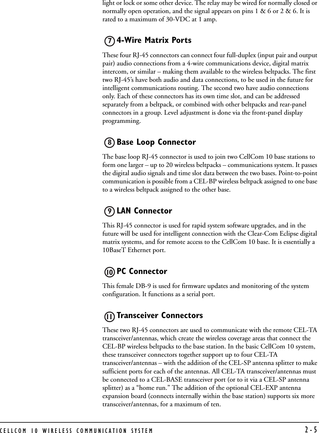


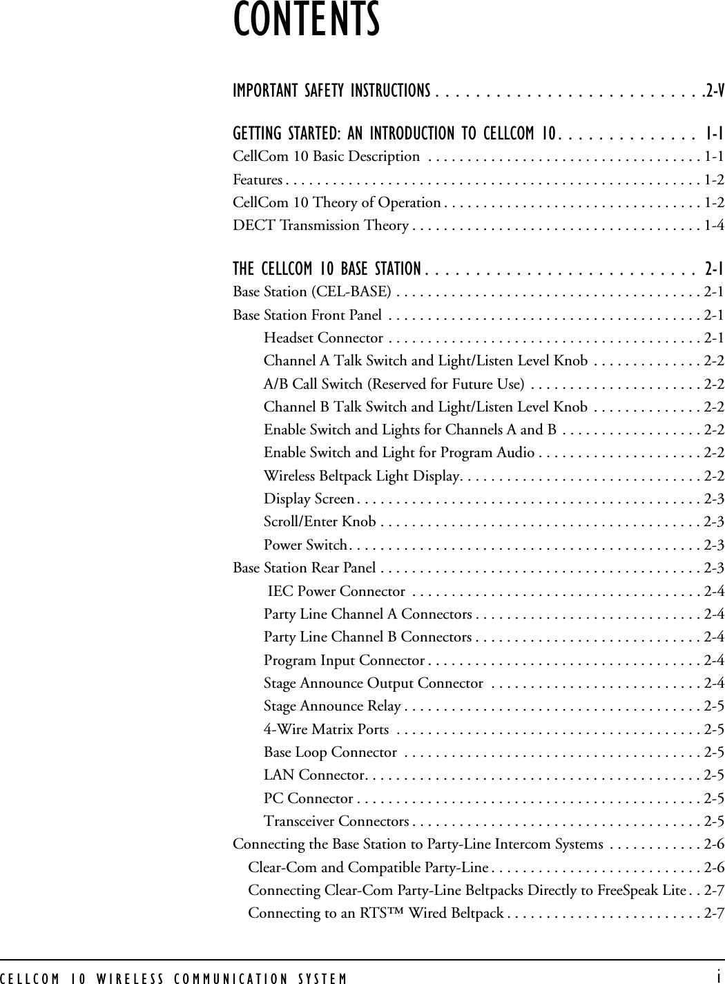
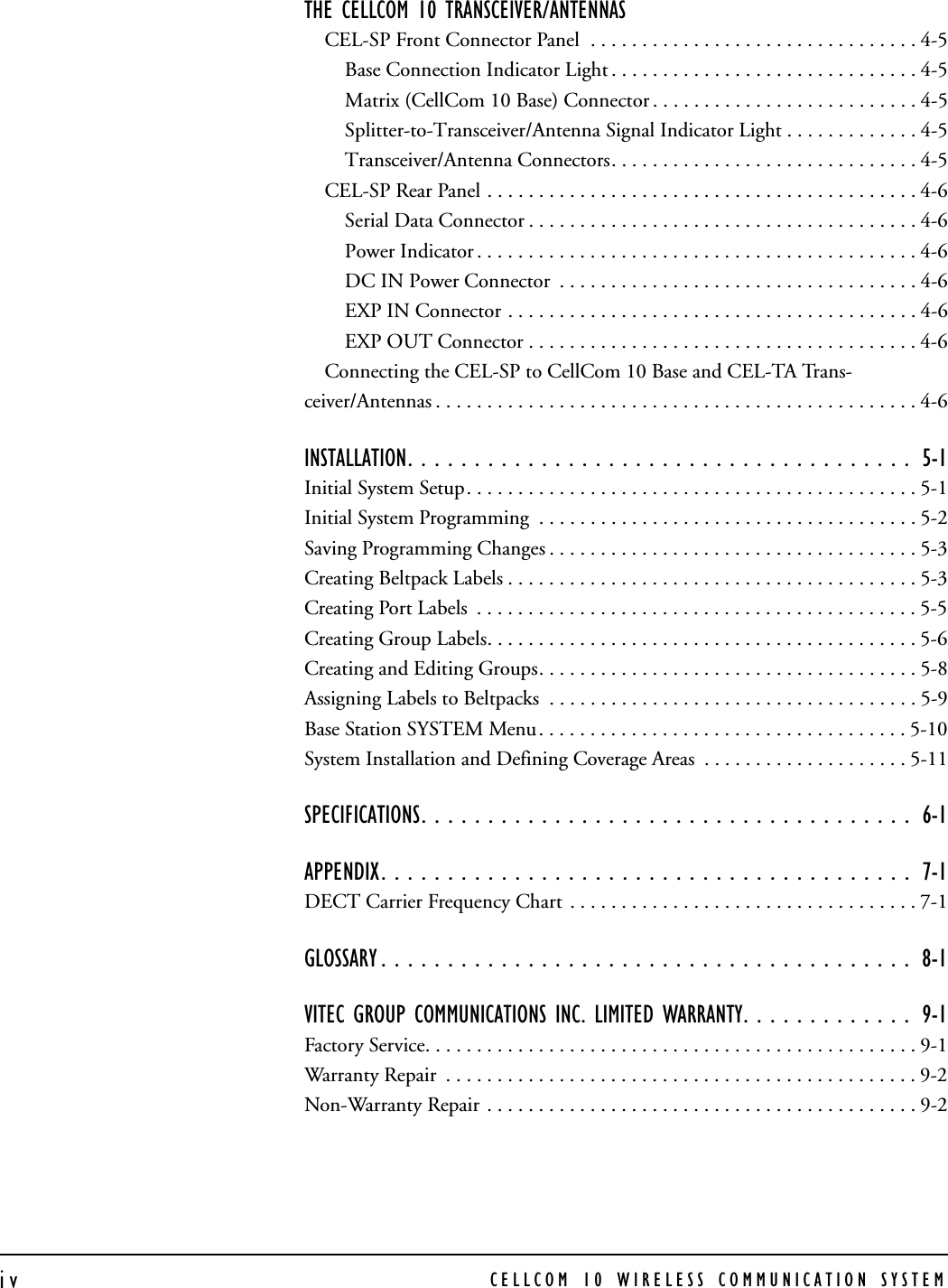
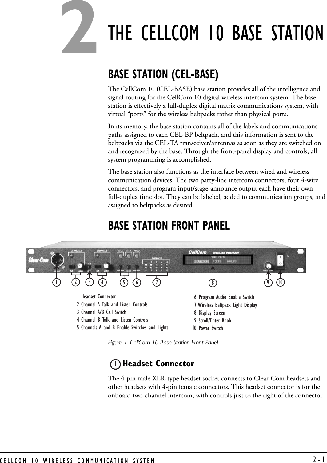
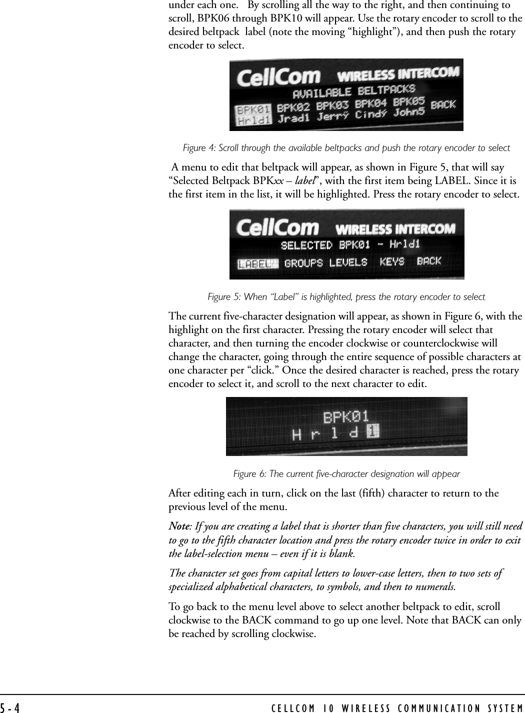
![CELLCOM 10 WIRELESS COMMUNICATION SYSTEM 5-1INSTALLATION INITIAL SYSTEM SETUP A CellCom 10 system can work out of the box, as long as the beltpacks are registered to the base, using the generic user labels for the beltpacks and the rear-panel connections. The first stage in setup is placing the base station in a convenient location, knowing that it is the central routing unit of the CellCom 10 system. It is also the means of programming the system, creating and changing user labels, and creating and modifying the groups and communications paths within the overall system. You will want to make it accessible.At this stage, if they are unregistered, you may want to register the beltpacks, or at least one or two for system setup and testing, with the base station. Follow the instructions in the section titled Registering Beltpacks with the Base Station in the CEL-BP beltpack section of the manual.The next step is to determine where the CEL-TA transceiver/antennas will be located to provide the necessary coverage areas for all of the beltpacks [See section below on System Installation and Defining Coverage Areas]. What areas will have more than 5 active beltpack users in them at any time? Co-locate a second CEL-TA there. Is there a central place to locate a transceiver/antenna so that it will provide omnidirectional (all directions / circular) coverage? Are there balcony areas, corridors, or other rooms or areas that will require coverage with transceiver/antennas? Then figure out where the CEL-SP splitter(s) that feed these transceiver/antennas will be safely located. [For systems with only one or two CEL-TA transceiver/antennas, the cable runs will go directly from the two transceiver ports on the base station.]Run 4-pair CAT-5 cable from the CellCom 10 base to the splitter, and determine that the splitter is showing both power (green LED lit) and signal (yellow LED lit when the base station is on). Run 4-pair CAT-5 cable from the splitter to each of the CEL-TA transceiver/antennas. Make sure that the local power supplies are plugged into the CEL-TA’s, unless they are close enough to the base station to draw power from the attached CAT-5 cable. You will know that the CEL-TA has sufficient power from the cable if the green power LED and the yellow data LED light up. If you have several longer runs and are attempting to power the transceiver/antennas from the base / splitter connection, check each one again when the are all connected. The local powering for the CEL-TA is recommended in most cases to provide the most reliable long-term CellCom 10 installation.Note that 4-pair CAT-5 cable with RJ-45 connectors on each end is specified for connection between the CEL-BASE base station and the CEL-TA 5](https://usermanual.wiki/Vitec-Group-Communications/CEL-BP/User-Guide-598461-Page-51.png)
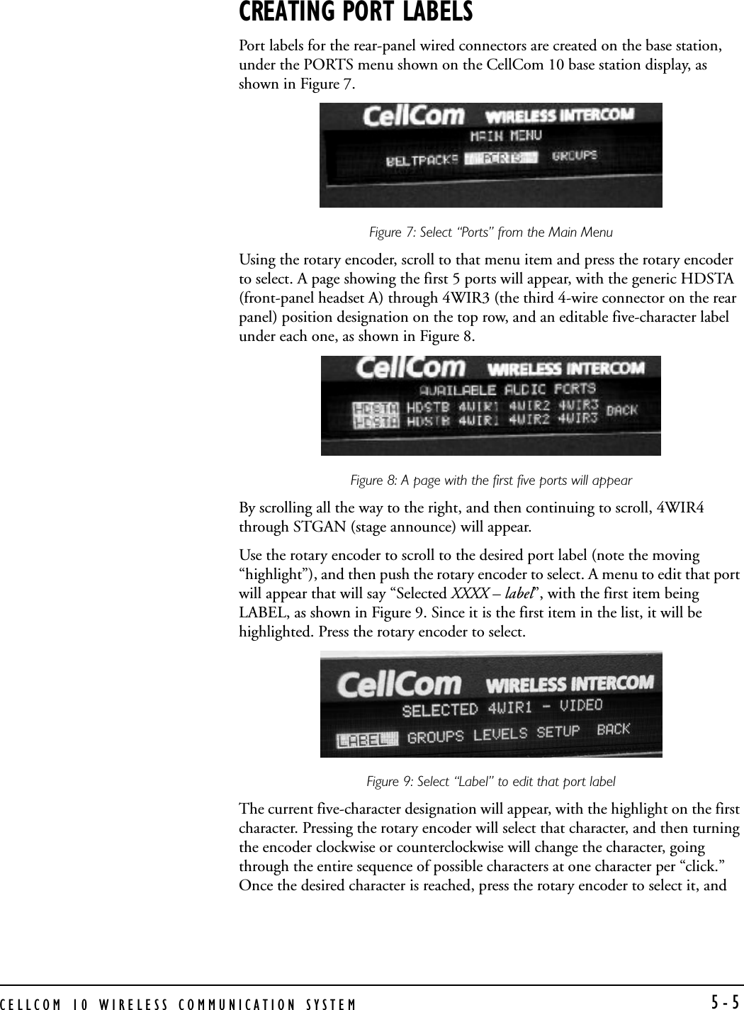
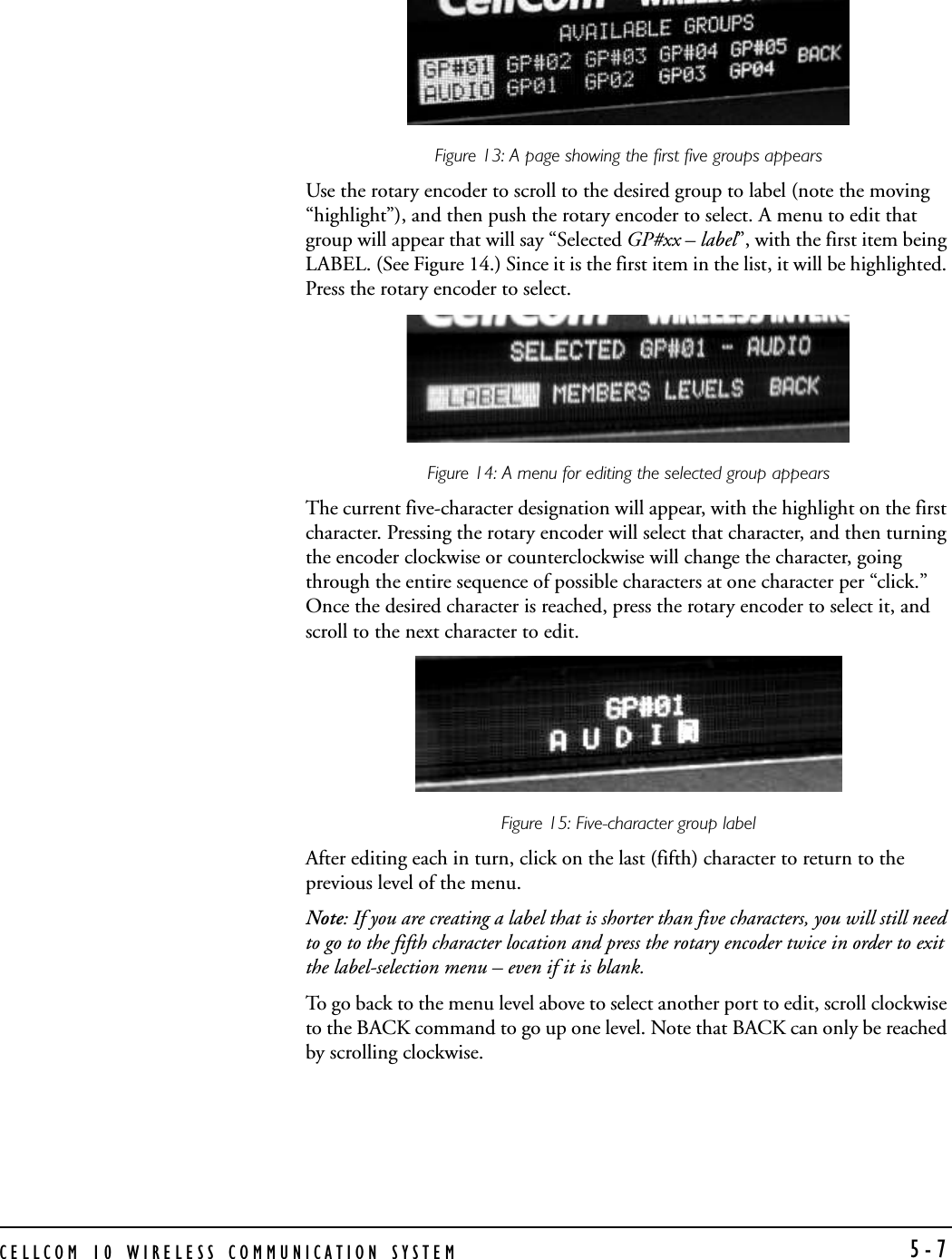
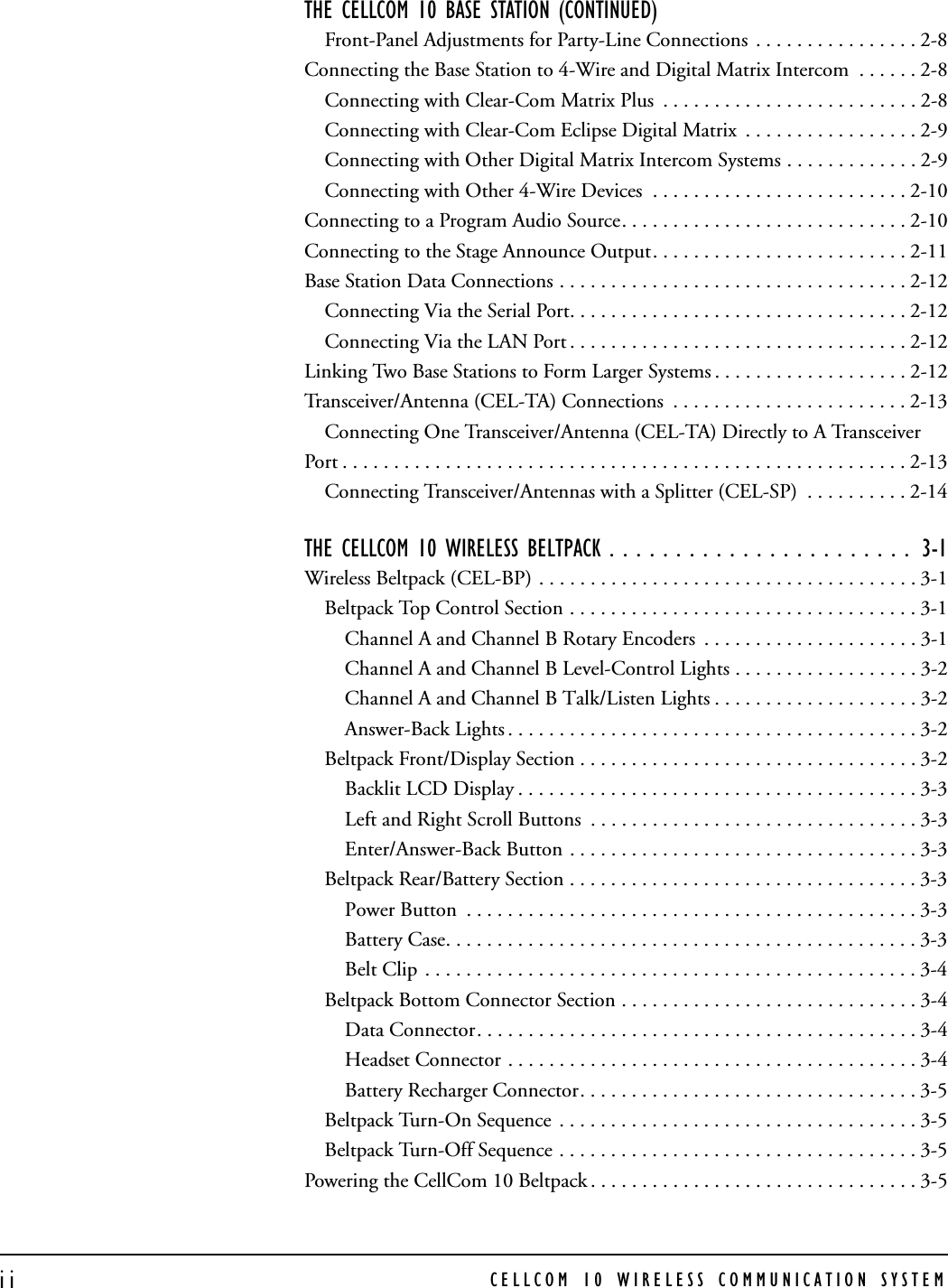
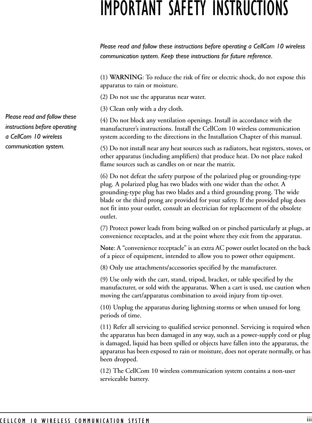
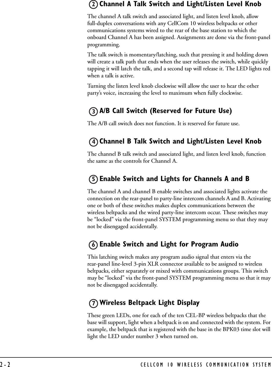
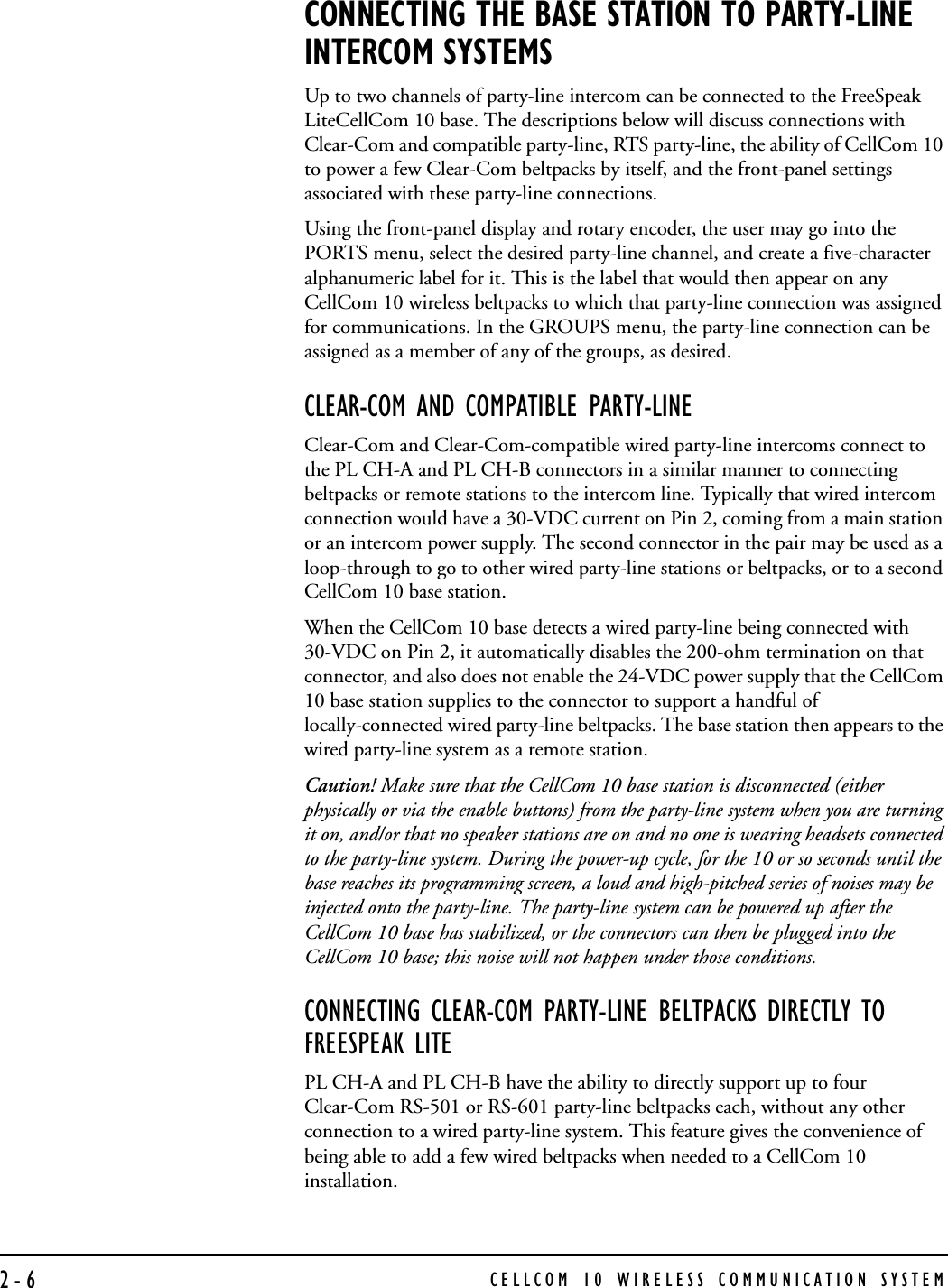
![CELLCOM 10 WIRELESS COMMUNICATION SYSTEM5-6scroll to the next character to edit. A five-character editable label is shown in Figure 10.Figure 10: Five-character editable label After editing each in turn, click on the last (fifth) character to return to the previous level of the menu, as shown in Figure 11.Figure 11: After editing the label, return to the previous menuNote:If you are creating a label that is shorter than five characters, you will still need to go to the fifth character location and press the rotary encoder twice in order to exit the label-selection menu – even if it is blank]. To go back to the menu level above to select another port to edit, scroll clockwise to the BACK command to go up one level. Note that BACK can only be reached by scrolling clockwise.CREATING GROUP LABELSGroup labels that combine selected individual beltpack and rear-panel labels are created on the base station, under the GROUPS menu shown on the CellCom 10 base station display. (See Figure 12.) Using the rotary encoder, scroll to that menu item, and press the rotary encoder to select.Figure 12: Select “Groups” from the Main Menu A page showing the first 5 groups will appear, with the generic GP#01 (first group, initially labeled GP00 in the editable field) through GP#05 position designation on the top row, and an editable 5-character label under each one. (See Figure 13.) By scrolling all the way to the right, and then continuing to scroll, GP#06 through GP#10 will appear.](https://usermanual.wiki/Vitec-Group-Communications/CEL-BP/User-Guide-598461-Page-56.png)