Vivint AP02 Indoor/Outdoor Wireless Access Point User Manual
Vivint. Inc. Indoor/Outdoor Wireless Access Point Users Manual
Vivint >
Users Manual

SR1430
Outdoor Wireless AP
Installation and User Guide
Version 0.01
4931 NORTH 300 WEST
PROVO, UT 84604
T: 801.377.9111
F: 801.377.4116
SR1430 Installation and User Guide Page 2
SR1430 Installation and User Guide Ver. 0.01
Record of Changes
Manual Version /
Date Description
0.01 Aug 31, 2014 Preliminary version

SR1430 Installation and User Guide Page 3
SR1430 Installation and User Guide Ver. 0.01
Notices
This product contains software proprietary to Vivint and protected by US and International copyright law.
Unauthorized reproduction or disclosure, in whole or in part, is strictly prohibited.
The software and methods implemented in this product may be protected by US Patents:
Patent Application Name Patent
Application
Number
Jurisdiction of
Grant
DYNAMIC ROUTING WITHIN A
WIRELESS MESH NETWORK 61/794,869 U.S.
DYNAMIC ADJUSTMENT OF
QUALITY OF SERVICE
PARAMETERS IN RESPONSE
TO CHANGING NETWORK
CONDITIONS
61/785,074 U.S.
SYSTEM FOR MINIMIZING
INTERFERENCE THROUGH
SIMULTANEOUS CHANNEL
SWITCHING WITHIN A MESH
NETWORK, AND METHODS,
DEVICES, SOFTWARE, AND
COMPUTER-READABLE MEDIA
ASSOCIATED THEREWITH
61/784,795 U.S.
MULTICAST TRAFFIC
MANAGEMENT WITHIN A
WIRELESS MESH NETWORK
61/794,968 U.S.
BANDWIDTH ESTIMATION
BASED ON LOCATION IN A
WIRELESS NETWORK
61/793,415 U.S.
SYSTEMS AND METHODS FOR
EXTENDING BROADBAND
ACCESS THROUGH A
WIRELESS MESH NETWORK
61/793,177 U.S.
This device complies with FCC Part 15 of the FCC Rules. Operation is subject to the
following two conditions: (1) this device may not cause harmful interference, and (2)
this device must accept any interference received, including interference that may
cause undesired operation.
Caution, changes or modifications not expressly approved by Vivint could void the
user’s authority to operate the equipment.
Note: This equipment has been tested and found to comply with the limits for a Class
B digital device, pursuant to Part 15 of the FCC Rules. These limits are designed to
provide reasonable protection against harmful interference when the equipment is
operated in a residential environment. This equipment generates, uses, and can

SR1430 Installation and User Guide Page 4
SR1430 Installation and User Guide Ver. 0.01
radiated radio frequency energy and, if not installed and used in accordance with the
instruction manual, may cause harmful interference to radio communications.
However, there is no guarantee that interference will not occur in a particular
installation. If this equipment does cause harmful interference to radio or television
reception, which can be determined by turning the equipment off and on, the user is
encouraged to try to correct the interference by one or more of the following
measures:
Reorient or relocate the receiving antenna.
Increase the separation distance between the equipment and receiver.
Connect the equipment into an outlet on a circuit different from that to which
the receiver is connected.
Consult the dealer or an experienced radio/TV technician for help.
RF Exposure: In order to comply with radio frequency (RF) exposure limits, the
antennas for this product should be positioned no less than 20 cm from your body or
nearby persons.

SR1430 Installation and User Guide Page 5
SR1430 Installation and User Guide Ver. 0.01
Copyright
SR1430 Outdoor Wireless AP Router, Installation and User Guide, Version 0.01
© 2013. Vivint Wireless All right reserved.

SR1430 Installation and User Guide Page 6
SR1430 Installation and User Guide Ver. 0.01
TABLEOFCONTENTS
1.0INTRODUCTION 7
1.1.1DATA RATES 8
1.1.2RADIO PATH PLANNING 8
1.1.3DEVICE HEIGHT 9
1.1.4ANTENNA POSITION AND POLARIZATION 9
1.1.5RADIO INTERFERENCE 10
1.1.6WEATHER CONDITIONS 10
1.2ETHERNET CABLING 10
1.3GROUNDING 11
SYSTEM SETUP 13
1.4ADMINISTRATION 13
1.4.1ADDING USERS & CHANGING PASSWORD 13
1.4.2UPGRADING FIRMWARE 13
1.5SYSTEM LOG 14
1.5.1ENABLING SYSTEM LOGGING 14
2.0HARDWARE INSTALLATION 15
2.1BEFORE INSTALLING 15
2.1.1TESTING BASIC LINK OPERATION 16
3.0SPECIFICATIONS 16
3.1PRODUCT FEATURES 16
3.2ETHERNET COMPATIBILITY 16
3.3POWER OVER ETHERNET 16
3.4RADIO CHARACTERISTICS 16

SR1430 Installation and User Guide Page 7
SR1430 Installation and User Guide Ver. 0.01
1.0 Introduction
The Vivint SR1430 is an 802.11n beamforming indoor/outdoor-rated wireless Access Point
(AP) /Wireless Distribution System (WDS) designed for the deployment of advanced IEEE
802.11 wireless services in harsh environments. SR1430 is a POE device.
The SR1430 is capable of filtering, classifying, shaping, forwarding Layer 3 traffic.
The SR1430 devices are NOT sold through authorized or non-retail distribution channels. They
are installed and commissioned by professional Vivint Installer / Qualified Network
Administrator/Vivint-NOC. The professional Installer ensures that the configuration and
operation of AP’s complies with local regulations, frequencies, channels and output power.
Product Improvements and Upgrades
Vivint reserves the right to make changes and/or improvements to its products, without
notification and without incurring any obligation to incorporate such changes or improvements
in products previously sold or shipped.
SR1430 Installation and User Guide Page 8
SR1430 Installation and User Guide Ver. 0.01
1.1.1 Data rates
Under ideal deployment conditions (low line of sight, low interference, and low moisture
content), the SR1430 router can operate over a range of up to 1 km or provide a high-speed
connection of 100 Mbps The range also depends on the type of antenna used. The maximum
data rate for a link decreases as the operating range increases.
When planning a wireless router link, take into account the maximum distance and data rates
for the various antenna options.
.
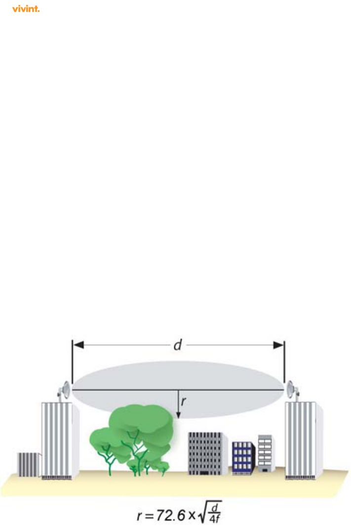
1.1.2 Radio Path Planning
The wireless router link requires a “radio line of sight” between the two antennas for optimum
performance.
The concept of radio line of sight involves the area along a link through which the bulk of the
radio signal power travels. This area is known as the first Fresnel Zone of the radio link. For a
radio link, no object (including the ground) must intrude within 60% of the first Fresnel Zone.
The following figure illustrates the concept of a good radio line of sight.
If there are obstacles in the radio path, there may still be a radio link but the quality and
strength of the signal would be affected. Calculating the maximum clearance from objects on a
path is important as it directly affects the decision on antenna placement and height. It is
especially critical for long-distance links, where the radio signal could easily be lost.
NOTE: For wireless links less than 500 m, the IEEE 802.11a radio signal will tolerate some
obstacles in the path and may not even require a visual line of sight between the antennas.
When planning the radio path for a wireless router link, consider these factors:
SR1430 Installation and User Guide Page 9
SR1430 Installation and User Guide Ver. 0.01
Avoid any partial line of sight between the antennas
Be cautious of trees or other foliage that may be near the path, or may grow and obstruct the
path
Be sure there is enough clearance from buildings and that no building construction may
eventually block the path
Check the topology of the land between the antennas using topographical maps, aerial photos,
or even satellite image data (software packages are available that may include this
information for your area)
Install the device at the customer home rooftop at a spot that meets the above requirements.
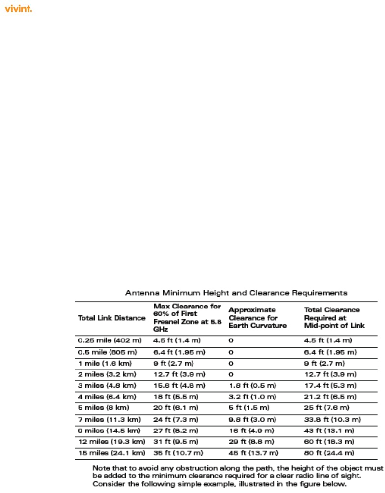
1.1.3 Device Height
A reliable wireless link is achieved by mounting the antennas at each end, high enough for a
clear radio LOS (line of sight) between them. The minimum height required depends on the
distance of the link, obstacles that may be in the path, topology of the terrain, and the curvature
of the earth (for links over 3 miles). Use the following table to estimate the required minimum
clearance above the ground or path obstruction.
1.1.4 Antenna Position and Polarization
Once the required antenna height has been determined, other factors affecting the precise
position of the AP to be considered are given below.
Ensure that there are no other radios/antennas within 2 m (6 ft) of the wireless router. These include
other WLAN radios/antennas.
Place the wireless router away from power and telephone lines
Avoid placing the AP too close to any metallic reflective surfaces, such as roof-Installed air-
conditioning equipment, tinted windows, wire fences, or water pipes. Ensure that there is at least 5
feet clearance from such objects
For maximum throughput, the AP and CPE should be aligned/matched polarization.

SR1430 Installation and User Guide Page 10
SR1430 Installation and User Guide Ver. 0.01
1.1.5 Radio Interference
The avoidance of radio interference is an important part of wireless link planning. Interference
is caused by other radio transmissions using the same or an adjacent channel frequency. You
should first scan your proposed site using a spectrum analyzer to determine if there are any
strong radio signals using the 802.11a/n channel frequencies and for the presence of TDWR
transmissions. Vivint professional installer then passes on the site survey details to the Vivint-
NOC, which in turn verifies the same prior to configuring the SR1430.
1.1.6 Weather Conditions
When planning wireless links, you must take into account any extreme weather conditions that
are known to affect your location. Consider these factors:
Temperature — The SR1430 is tested for normal operation in temperatures from -33°C to 55°C.
Operating in temperatures outside of this range may cause the unit to fail.
Wind Velocity — The SR1430 can operate in winds up to 90 miles per hour and survive higher wind
speeds up to 125 miles per hour. You must consider the known maximum wind velocity and direction
at the site and be sure that any supporting structure, such as a pole, mast, or tower, is built to
withstand this force.
Lightning — The SR1430 includes its own built-in lightning protection via chassis grounding.
However, you should make sure that the unit, any supporting structure, and cables are all properly
grounded. Additional protection using lightning rods, lightning arrestors, or surge suppressors may
also be employed.
Rain — The SR1430 is weatherproof. Also, prolonged heavy rain has no significant effect on the
radio signal. However, it is recommended to use weatherproof boots on cables connecting to the
SR1430 or to apply weatherproof sealing tape around connectors for extra protection. If moisture
enters a connector, it may cause a degradation in performance or even a complete failure of the link.
Snow and Ice — Falling snow, like rain, has no significant effect on the radio signal. However, a
buildup of snow or ice on antennas may cause the link to fail. In this case, the snow or ice
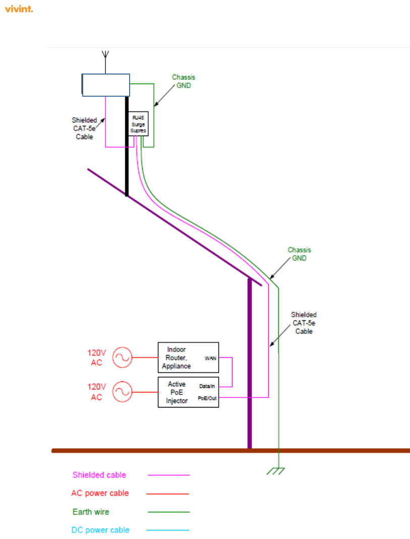
1.2 Ethernet Cabling
When a suitable antenna location has been determined, you must plan a cable route from the
SR1430 wireless router outdoors to the equipment indoors. If a power injector/adapter module
is used, it is for indoor Installation only. Consider these points:
The Ethernet cable length should never be longer than 90 m (295 ft)
Determine a building entry point for the cable
Determine if conduits, bracing, or other structures are required for safety or protection of the cable
For lightning protection at the power injector end of the cable, consider using Surge protectors.
SR1430 Installation and User Guide Page 11
SR1430 Installation and User Guide Ver. 0.01
Example Installation is shown below.
1.3 Grounding
It is important that the wireless router, cables, and any supporting structures are properly
grounded. The wireless router unit includes a grounding screw for attaching a ground wire. Be
sure that grounding is available and that it meets local and national electrical codes.
SR1430 Installation and User Guide Page 12
SR1430 Installation and User Guide Ver. 0.01
The Installation sequence is given below.
AP
SR1430

SR1430 Installation and User Guide Page 13
SR1430 Installation and User Guide Ver. 0.01
System Setup
The SR1430 is setup by the Vivint professional Installer/technician and governed by the Vivint-NOC
(Network Operations Center). The Vivint-NOC configures the device including the IP address
assignment, operating channel allocation etc. It also ensures that if the service area is within 35Km of
TDWR locations, then SR1430 is configured to avoid operation within 30MHz for each of the TDWR’s
located within the service area.
After commissioning, the Vivint-NOC also registers the service area location information in the
following link - http://udia.spectrumbridge.com/udia/home.aspx).
1.4 Administration
1.4.1 Adding Users & Changing Password
The administration of the SR1430 is governed by the Vivint-NOC (Network Operations Center)
Usage: adduser [OPTIONS] user_name
Add an user
Options:
-h DIR Home directory
-g GECOS GECOS field
-s SHELL Login shell
-G GROUP Add user to existing group
-S Create a system user
-D Do not assign a password
-H Do not create home directory
Usage: passwd
Change password of an user
1.4.2 Upgrading Firmware
The SW/FW upgradation is governed by the Vivint-NOC (Network Operations Center) and the end-
user doesn’t have access to the device.
1. Mount the AP on its fixture without touching the pins of the Radio RJ45 connector.
2. Patch cable from radio to Citel (SPD) - Make a shielded CAT5e cable such that its shielding foil is grounded to the
metal shielding of the RJ45 connectors at either end as shown in slide#10
3. Connect one end of the cable to the radio and the other end to the “IN” port on the Citel surge suppressor
4. Use 12AWG wire to connect the surge suppressor center ground ping to building common ground
5. Make another shielded CAT5e cable that has RJ45 shielded connectors at both ends. Connect one end to
the remaining RJ45 port on Citel suppressor, and the other end to the PoE injector as shown in slide #12
6. Check for GND continuity as shown in slide#12
7. Power up the PoE injector last and check functionality.

SR1430 Installation and User Guide Page 14
SR1430 Installation and User Guide Ver. 0.01
1.5 System Log
/var/log/message keeps a circular log in memory, no filesystem activity involved.
1.5.1 Enabling System Logging
To read the logfile from syslogd you should use the logread command, which outputs the
messages in syslogd's circular buffer.
Logging is always enabled.

SR1430 Installation and User Guide Page 15
SR1430 Installation and User Guide Ver. 0.01
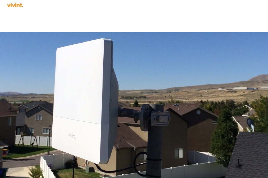
2.0 Hardware Installation
The SR1430, is a wireless AP device is designed to be deployed outdoors, exposed to all
elements (extreme heat or sun, rain, snow, ice, cold) and mounted on a wall, pole, or mast.
The SR1430 is supplied complete with its own mounting hardware kit for attaching the unit to a
1-2.5” diameter metal pole or tube or as part of a radio mast or tower structure.
The supplied SR1430 48V power supply is suitable for outdoor use.
The optional SR1430 indoor-rated Power over Ethernet injector (Vivint part #9004H49000)
must be deployed indoors, or within an enclosure protecting it from the elements.
Hardware Installation of the wireless router involves these steps:
1. Mount the SR1430 unit as shown in section 1.2 (example installation).
2. Connect a grounding wire to the SR1430 unit.
3. Connect the Ethernet cable to the SR1430 unit.
4. Connect the power supply to the SR1430, and to an AC power source.
5. Connect the power injector (if used) to the Ethernet cable, a local LAN switch, and
an AC power source.
6. Align antennas at both ends of the link.
Before mounting antennas to set up your wireless links, be sure you have selected appropriate
locations for each antenna. Follow the guidance and information in “Link Planning.”
Also before mounting units in their intended locations, you should first configure the devices as
described in Section 0 “System Setup” and Section Error! Reference source not found. ,
“System Configuration.” You should also test the basic operation of the wireless router links in
a controlled environment over a very short range, as described in “Testing Basic Link
Operation”, Section 2.1.1.
2.1 Before Installing
Before Installing the SR1430, verify the following:
Outdoor Ethernet cable of required length of 50 meters (164 feet), or a cable meeting the pin-out
configuration specification to the required length (not to exceed 90 meters total), shielded CAT-5
Ethernet 8-pin DIN to RJ-45
Power supply shipped with the SR1430
An appropriate and APble mounting location
A suitable electrical grounding point (on AP mounting mast/pole)
Appropriate tools (wrench for mounting bolts, Phillips head screwdriver, DC voltmeter (if RSSI-
based link alignment is to be performed))
Mounting items not supplied with the SR1430 — screws, bolts, and straps — should be
available and at hand prior to Installation.
Due to the typically inaccessible location often best suited to deploying an outdoor wireless
router (for example, on rooftops, sides of buildings, or on a radio tower) it is recommended that

SR1430 Installation and User Guide Page 16
SR1430 Installation and User Guide Ver. 0.01
the network administrator pre-provision the SR1430 system to be Installed (taking note of
settings, passwords, Channel, MAC and IP addresses) prior to physical Installation, and
confirm that the device is fully operational and free from fault.
2.1.1 Testing Basic Link Operation
Set up the units over a very short range (15 to 25 feet), either outdoors or indoors. Connect the
units as indicated in this chapter and be sure to perform all the basic configuration tasks
outlined in “System Setup.” When you are satisfied that the links are operating correctly,
proceed to mount the units in their intended locations.
3.0 Specifications
3.1 Product features
IEEE802.11n Wireless AP, 40MHz operation.
Seamless connectivity to wired LANs augment existing networks quickly and easily
3.2 Ethernet Compatibility
The SR1430 Outdoor Wireless AP attaches to 10/100 Mbps Ethernet (FE) LAN segments that
utilize 10Base-T/100Base-TX (twisted-pair) wiring. The device appears as an Ethernet node
and performs a routing function by moving packets between the wired LAN and remote
workstations on the wireless infrastructure.
3.3 Power Over Ethernet
The SR1430 Outdoor Wireless AP supports non-standard Power Over Ethernet (POE)
3.4 Radio Characteristics
The SR1430 is an IEEE802.11n compliant outdoor Wireless AP.
802.11n provides a high data rate and reliable wireless connectivity. IEEE 802.11n operation uses
a radio modulation technique known as Orthogonal Frequency Division Multiplexing (OFDM),
and a shared collision domain (CSMA/CA). It operates in the 5 GHz Unlicensed National
Information Infrastructure (UNII) band. Data is transmitted over a half-duplex radio channel
operating at up to 300 Megabits per second (Mbps)