Vivint AP03 Indoor/Outdoor Wireless Access Point User Manual
Vivint. Inc. Indoor/Outdoor Wireless Access Point Users Manual
UserManual.wiki
>
Vivint
>
AP03 User Manual
Users Manual
Navigation menu
Upload a User Manual
Namespaces
Wiki Guide
HTML
PDF
Info
Views
User Manual
Discussion / Help
Navigation
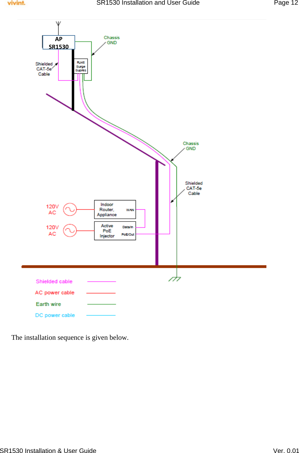
![SR1530 Installation and User Guide Page 13 SR1530 Installation & User Guide Ver. 0.01 System Setup The SR1530 is setup by the Vivint professional installer/technician. 1.4 Administration 1.4.1 Adding Users & Changing Password The administration of the SR1530 is governed by the Vivint-NOC (Network Operations Center) Usage: adduser [OPTIONS] user_name Add an user Options: -h DIR Home directory -g GECOS GECOS field -s SHELL Login shell -G GROUP Add user to existing group -S Create a system user -D Do not assign a password -H Do not create home directory Usage: passwd Change password of an user 1.4.2 Upgrading Firmware The SW/FW upgradation is governed by the Vivint-NOC (Network Operations Center) and the end-user doesn’t have access to the device. 1.5 System Log /var/log/message keeps a circular log in memory, no filesystem activity involved. 1.5.1 Enabling System Logging To read the logfile from syslogd you should use the logread command, which outputs the messages in syslogd's circular buffer. Logging is always enabled. 1. Mount the AP on its fixture without touching the pins of the Radio RJ45 connector. 2. Patch cable from radio to Citel - Make a shielded CAT5e cable such that its shielding foil is grounded to the metal shielding of the RJ45 connectors at either end as shown in slide#10 3. Connect one end of the cable to the radio and the other end to the “IN” port on the Citel surge suppressor 4. Use 12AWG wire to connect the surge suppressor center ground ping to building common ground 5. Make another shielded CAT5e cable that has RJ45 shielded connectors at both ends. Connect one end to the remaining RJ45 port on Citel suppressor, and the other end to the PoE injector as shown in slide #12 6. Check for GND continuity as shown in slide#12 7. Power up the PoE injector last and check functionality.](https://usermanual.wiki/Vivint/AP03/User-Guide-2706605-Page-13.png)