Users Manual

SETUP GUIDE
Smart Hub
Panel
a

© 2016 Vivint, Inc. All rights reserved.
VivintanditsrespectivelogosareregisteredtrademarksortrademarksofVivint,Inc.intheUnitedStatesand
othercountries.Allothertrademarksarethepropertyoftheirrespectiveowners.
DISCLAIMER:Nopartofthismaterialmaybeexcerpted,reproduced,redistributed,published,broadcast,transmitted,translated,orutilized
inanyformorbyanymeans,electronic,mechanical,photocopying,recording,orotherwise,withoutpriorwrittenpermissionofVivint,Inc..
Vivintdoesnotwarrantthatthisdocumentiserrorfreeandretainstherighttomakechangestothisdocumentorrelatedproduct
specifications,drawings,anddescriptionsatanytimewithoutnotice.Vivintdoesnotassumeanyobligationtoupdatetheinformation
containedherein.Thisdocumentisprovided"ASIS"andwithoutanyguaranty,warranty,orlicense,expressorimplied,includingbutnot
limitedto:fitnessforaparticularpurpose,merchantability,non-infringementofintellectualproperty,orotherrightsofanythirdparty.
AnyVivintproductsreferencedinthisdocumentarenotintendedforuseinmedical,lifesaving,orlifesustainingapplications.
Thirdpartiesmayhaveintellectualpropertyrightsrelevanttothisdocumentandthetechnologiesdiscussedherein.
Setup Guide
Released:10/17/2016
DocumentPartNumberP/N:77-600017-001—RevA.0
PanelPartNumberP/N:V-SH1
PanelComplianceModelNumberM/N:CP02

- 1 -
Contents
Contents 1
Introduction 3
About this Guide 3
SystemOverview 4
About the System 4
System Configuration Diagram 5
Control Panel Features 6
Control Panel Display Screens 10
SystemSetup 11
System Setup Outline and Summary 11
ConfigureSystemSettings 12
System Settings Configuration Outline 12
System Settings Complete List 13
Security Sensor Numbers and Types 14
Wireless Zones Configuration 17
Wired Zones Configuration 24
Key Fobs Configuration 28
Keypads Configuration 33
Entry and Exit Settings 36
Installer Settings 39
Key Fob Behavior Settings 42
Central Station Settings 43
Reporting and Troubles Settings 45
Emergency Buttons Settings 55
System Options Settings 56
System Registration Settings 59
Z-Wave Settings 60
Networking Settings 63
Cameras Settings 65
System Testing Settings 68
Cellular Settings 71
Sensor Bypass Settings 72
Bell Cutoff Settings 73

- 2 -
Update Settings 74
RegulatoryInformation 75
Where To Find Regulatory Compliance Declarations 75
FCC and IC Regulatory Compliance Declarations 76
Wireless Product Notice 77
Operating Temperature and Humidity Range Notice 77
Important Power Supply Notice 78
Internal Backup Battery Notice 78
Regulatory Notes 79
Applicable Warnings for Technicians 80
Default Settings for SIA CP-01-2014 Compliance 81
FCC and IC ID Numbers for System Devices 83
Fire Protection and Safety Information 84
Service and Warranty Information 88
Specifications 89
Introduction: About this Guide
- 3 -
Introduction
About this Guide
TheVivintSmartHub™panelisthehuboftheVivintSmartHome™system,afully-supervised,integrated,and
intelligenthomesecurityandautomationsystem.
Thesystem—whichincludesthecontrolpanelandvarioussecuritysensorsandperipheraldevices—
incorporatesthemostadvancedandsophisticatedfeaturesandtechnologyavailabletoday.Thesystemcanbe
expandedandcustomizedtofiteveryindividualhomeenvironmentandcustomerneed.
ThisguideprovidesanoverviewoftheentireVivintSmartHomesystem,informationabouthowthedifferent
componentsofthesystemworktogether,importantsafetystandardsandregulatorycompliancedeclarations,
andanoutlineoftheinstallation,setup,andsettingsconfigurationtasks.
Thefollowingtopicsarecoveredinthisguide:
l Learn about the control panelandoverallsystemfunctionality.
l Set up the control panelincludingplugginginthepowersupply,waitingforthepaneltobootup,andthen
followingtheonscreeninstructionsonthepanel'stouchscreendisplaythatstepsyouthroughtheprocess
ofaddingdevices(i.e.,sensors,cameras,etc.)andverifyingsuccessfuldeviceandpanelconnection.
l Configure system settingsforthepanel,securitysensors,andothersmarthomedevices.
NOTE:Somecitiesandmunicipalitiesmayrequireanalarmsystempermit.Checkwiththelocal
authoritiesbeforeinstallingthesystem.
IMPORTANT:AnychangesormodificationsnotapprovedbyVivintcouldvoidtheuser’sauthorityto
operatetheequipment.

Smart Hub Setup Guide
- 4 -
System Overview
About the System
ThissectionprovidesabriefsummaryofthemaincomponentsandfeaturesoftheVivintSmartHubsystem.
Control Panel
TheSmartHubpanelfeaturesacapacitive,colortouchscreendisplaythatallowscontrolofallsystemfunctions
andconfiguration.ThetouchscreendisplayshowstheVivintSmartHomeProtechnician(andthecustomer)
importantinformationsuchassystemanddevicestatus.Thecontrolpanelofferstouchnavigationthatmakes
systeminstallation,configuration,andoperationquickandeasy.
Thecontrolpanelhassystemsoftwareinstalledthatcanbeupdatedwiththelatestreleaseversionthatcan
includefeatureenhancements,fixes,andnewfunctionality.
Security Sensors
Thesystemcansupportupto100wirelesssensorsofvarioustypes(doorandwindowsensors,glassbreak
detectors,motiondetectors,etc.),aswellas20keyfobs,30keypads,and15sensorresponsetypes.
ThecontrolpanelreportssystemalarmsandtroublealertstotheVivintCentralStation(i.e.,MonitoringStation)
viaeithercellularorbroadbandIPnetworkcommunication.Two-wayvoicecommunicationbetweenthepaneland
theCentralStation(VivintLive)isalsoenabledthroughcellularcommunications.
A345MHznarrow-bandradioreceiverinsidethepaneldetectssignalstransmittedfromthewirelesssensors.
Z-Wave Devices
Thepanelhasabuilt-inZ-Waveradiomodulethatprovidessecure,encryptedcommunicationbetweenthepanel
andothersecurity-enabledZ-Wavedevices.Thepanel'sZ-Wavetechnologyallowsthecontrollingandmonitoring
ofvarioushomeautomationdevicessuchasdoorlocks,thermostats,andlightingcontroloutletmodules.
ThecontrolpanelwillworkwithanycompatibleZ-Wavedeviceregardlessofthemanufacturer.
User Accounts
TheVivintsystemsupports50useraccountsincludingasingleDuressUserandoneormoreAdminusers.The
Adminuserscanadd,delete,ormodifytheotherusers.NotethatalluserPINcodesmustbeunique.
TheInstallerPINcodeisassociatedwiththeonlyuseraccountthathasaccesstotheInstaller Toolboxscreens
(usedforconfiguringpanel,device,andsystemsettings).The default Installer PIN code is 2203.
Panel Buttons
ThepanelhasanEmergency buttonandaHome buttonthatfunctionasbothcontrolsandindicators.
Pressingthe buttonatanytimedisplaystheEmergencyscreenwithbuttonsforPanic,Emergency,andFire
alarmactivation(eachbuttonhasconfigurableoptionsandcanbeenabledanddisabledintheInstaller Toolbox).
Pressingthe buttonatanytimedisplaystheHomescreen.
System Overview: System Configuration Diagram
- 5 -
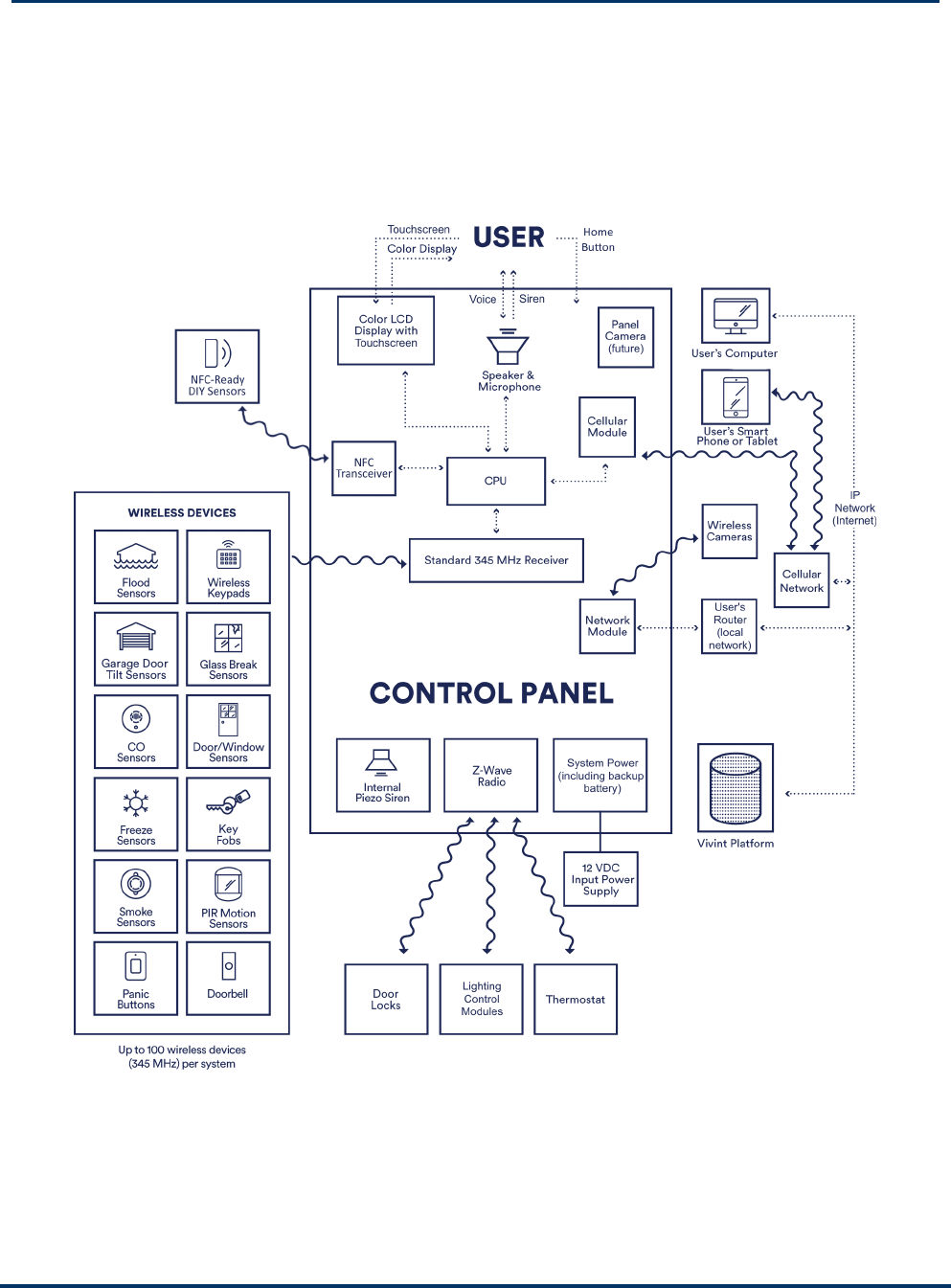
System Configuration Diagram
Thediagrambelowshowstheconfigurationofanoverallsystem—fortheVivintSmartHub™panel—andhow
itsvariouscomponentscommunicateandinteract,includingthecontrolpanel,userinputandinteractionfeatures,
internalmodules,wirelesssecuritysensors,NFC-readysensors(forDIYsetup),Z-Wavedevices,wireless
cameras,remoteaccessandcontroldevices(smartphone,tablet,laptop,etc.)viamobileandwebapps,power
supply,Wi-FicellularandbroadbandIPnetworks,andtheVivintPlatform.
Vivint Smart Hub Panel System
Smart Hub Setup Guide
- 6 -
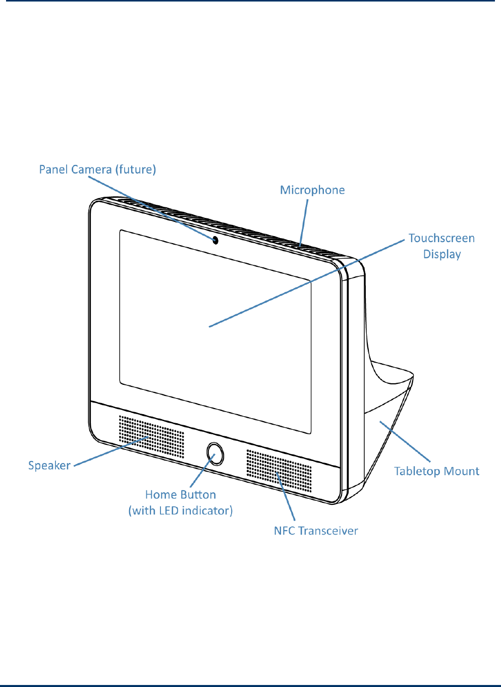
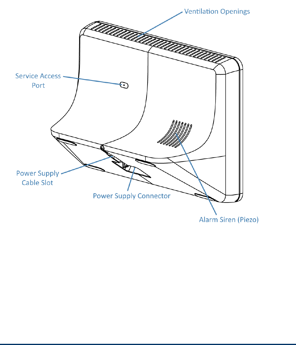
Control Panel Features
ThefollowingdrawingsshowtwoviewsoftheSmartHubcontrolpanel,withsomeofthemainfeaturescalledout.
First,anexternalfrontview;andsecond,anexternalbackviewofthepanel.
Panel Front View
System Overview: Control Panel Features
- 7 -
Panel Back View

Smart Hub Setup Guide
- 8 -
System Status as Indicated by the Home Button Display
TheHomebuttonLEDcanindicatethestatusofsystemfunctionsandconditions,asdescribedbelow.
Secur ity Sensor Status
l GlowsGreenwhenallofthesensorsareclosedandthesystemisreadytoarm.
l Notlitwhenanysensorisopenandthesystemisnotreadytoarm.
Ar mi ng Status
l GlowsRedwhilethesystemisarmed(ineitherStayorAwaymode).
l FlashesRedduringtheEntryDelaytimeperiod.
Al arm Status
l FlashesRedduringanalarm.
l FlashesRedafteranalarmwhilesystemisstillarmed.
Power Outage Status (on Backup Battery Power)
l FlashesGreenwhenallofthesensorsareclosedandthesystemisreadytoarm.
l FlashesOrangewhenanysensorisopenandthesystemisnotreadytoarm.
l FlashesRedwhilethesystemisarmed(ineitherStayorAwaymode).
System Overview: Control Panel Features
- 9 -
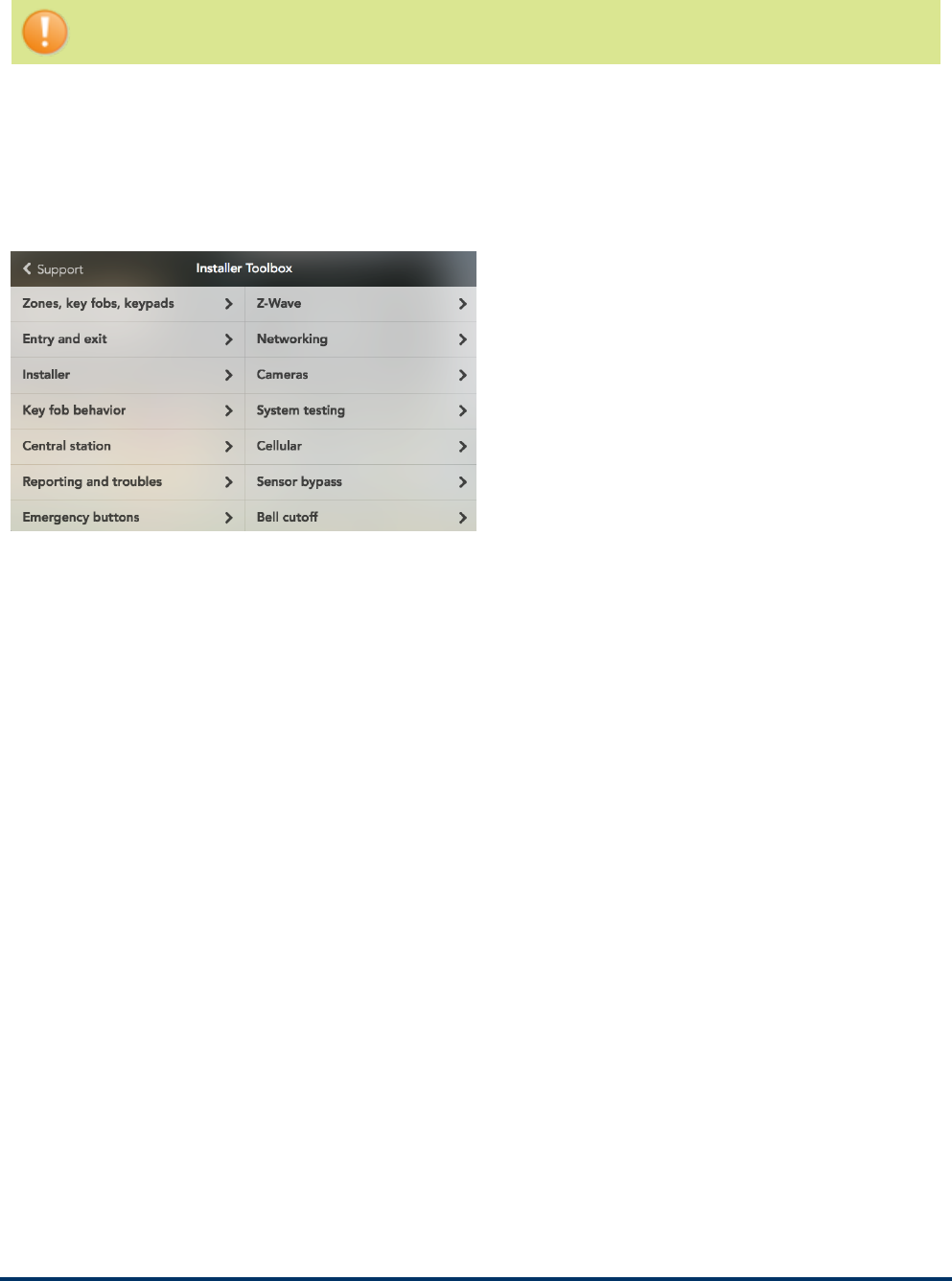
Installer Toolbox Screens
IMPORTANT:ThecompletesetofInstaller ToolboxscreensisaccessibleonlytoaVivintSmart
HomeProstechnicianwhoenterstherequiredInstallerPINcode.
UsetheInstaller Toolboxscreenstoconfiguresystemsettings.TheVivintSmartHomeProtechnicianmust
enteravalidInstallerPINcodetoaccessthistoolbox.Themainscreendisplaysasetofsystemconfiguration
andtestingtools.Usethesetoolstoconfigureallofthesystemsettings,testsystemfunctionality,andreset
systemoptionstodefaultvalues(fordetails,see"ConfigureSystemSettings"onpage12).
FromtheHomescreen,presstheMenubutton>Settings>entertheInstallerPINcode(thedefaultcodeis
2203)>andthenpressInstaller Toolbox.
Smart Hub Setup Guide
- 10 -
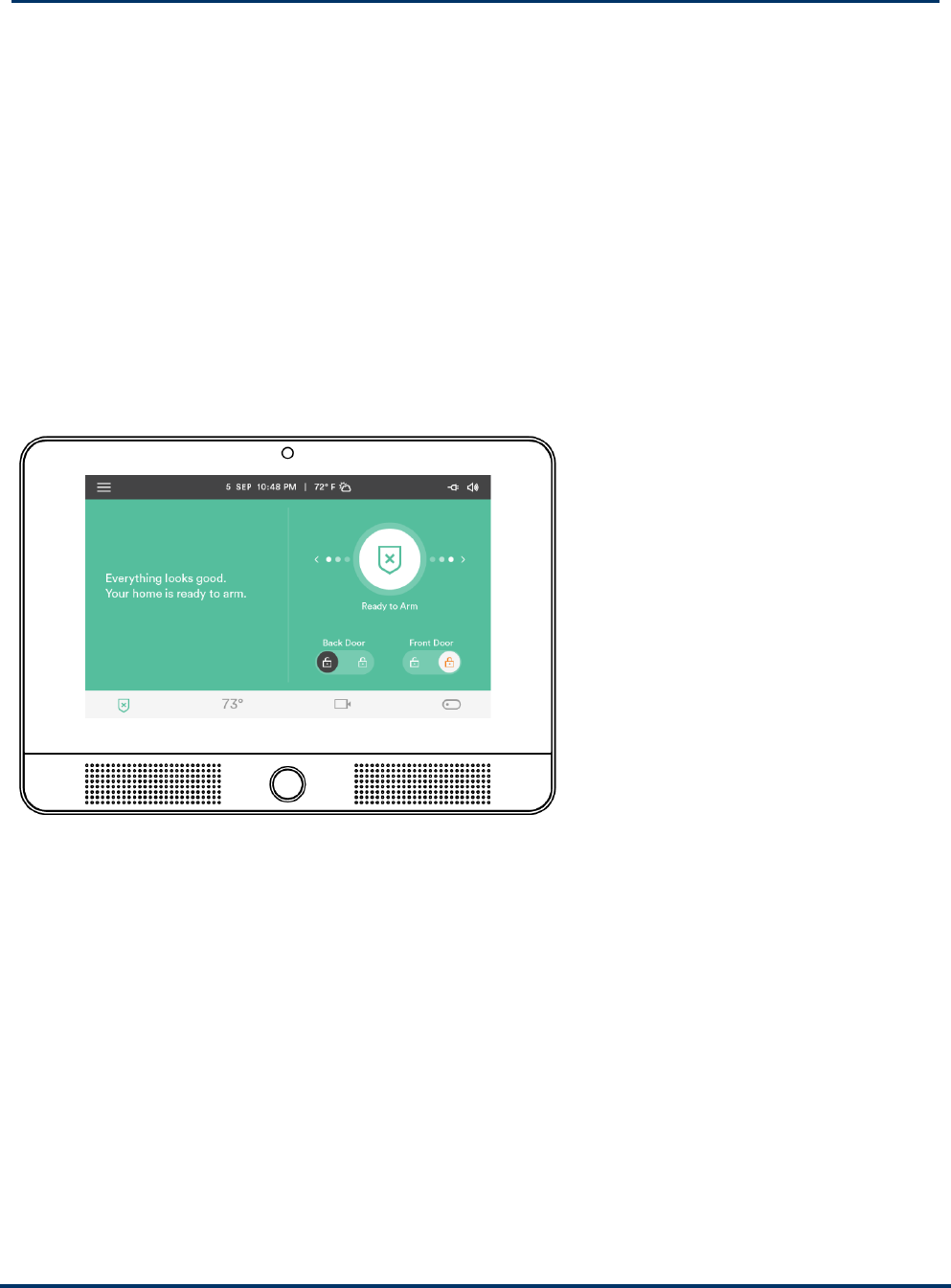
Control Panel Display Screens
TheVivintSmartHubpanelisconfiguredandoperatedusingthetouchscreendisplay.Thedisplayshowscritical
systeminformationandprovidesaccesstothenumerousfeaturesusedtoconfigure,monitor,andcontrolthe
homesecurityandautomationsystembyboththeVivintSmartHomeProtechnicianandthehomeowner.
Thestatus baratthetopofthetouchscreenprovidesMenuaccess,andshowssysteminformationsuchasthe
dateandtimeandweatherinformation,aswellasstatusiconsforalerts,messages,power(AC/battery),and
sound.
Thenavigation baratthebottomofthetouchscreenshowsthesecuritymode,andprovidesaccesstothe
connecteddevicessuchasdoorlocks,thermostats,cameras,lightingcontrols,andmore.
TheMenubuttonintheupperleftcornerofthetouchscreenletsyouaccessthefollowingscreens:Emergency,
Settings(includingtheInstaller Toolbox),andSupport.
Home Screen
Atanytime,presstheHomebuttononthetouchscreentoreturntotheHomescreen.

System Setup: System Setup Outline and Summary
- 11 -
System Setup
System Setup Outline and Summary
Thefollowingoutlineprovidesahigh-levelsummaryofallthetasksthatcomprisethesetupofaVivintSmartHub
panelandsystem.
1. Unpack the box.
UnpacktheSmartHubpanelboxandidentifythecontents.Thepackageshouldcontainthecontrolpanel,
powersupply,quicksetupcard,(NOTE:Youcanunpacktheotherdevices,suchassensorsand
cameras,atthistimebutdonotinstallthemyet.)
2. Locate an unswitched outlet for the power supply.
Identifyanunswitchedwalloutletwhereyoucanpluginthepowersupplyforthecontrolpanel.
3. Plug the power supply into the wall outlet.
Plugthepowersupplyintothepreviouslyidentifiedunswitchedwalloutlet.
4. Connect the power supply to the control panel.
Connectthepowersupplycabletotheportonthebacksideofthepanel,andthentuckthecablesnugly
intotheslot.
5. Wait for the panel to start up.
Waitforthepaneltoloadthefirmwareandforthetouchscreeninterfacetoappear.Donotinstallorplace
theperipheraldevicesyet(sensors,cameras,etc.),astheinitialpartofthesystemsetupisdescribedon
thepanelitselfviaonscreeninstructions.Pleasewaitforthepaneltobootupfirst,andforthatinitialsetup
screentoappear.Thisprocessmaytakeafewminutes.
6. Follow the onscreen instructions to add and configure devices.
Oncethepanelisfinishedbooting,followtheonscreeninstructionsthatwillguideyouthroughaddingand
configuringdevices,andfinishingthepanelsetup.
(Formoredetails,seetheseparatedocumententitled"SkyHubPanelDIYOnscreenSetupInstructions")

Smart Hub Setup Guide
- 12 -
Configure System Settings
System Settings Configuration Outline
IMPORTANT:ThecompletesetofInstaller ToolboxscreensisaccessibleonlytoaVivintSmart
HomeProstechnicianwhoenterstherequiredInstallerPINcode.Thissectiondescribesthecomplete
setofsystemsettings(whichmaynotbeavailabletothecustomerviatheUserSettingsinterface).
AstheVivinttechnician,youconfiguresystemsettingsatthecontrolpanelviatheInstaller Toolboxscreens.
Everysystemyouinstallrequiresthatyouconfiguresettingsforcertaininstalledmodulesinthepanel,security
sensorsandotherperipheraldevices,inadditiontospecificsystemfeaturesservices.
Thissectiondescribeshowtoconfigurethesesystemsettings,andprovidesdetailedinformationabouteachof
thesettingsincludingdefaultvalues,functionality,andcompliancerequirementsfortheAmerican National
Standards Institute / Security Industry Association,ANSI/SIA CP-01-2014standard,hereafterreferredtoin
itsabbreviatedformasSIA CP-01-2014.
Somesystemsettingsarecommonacrossallinstallations(forexample,allcontrolpanelsreporttothesame
CentralStation).Othersettings,suchasaccountnumberandsensoranddeviceconfiguration,areuniquetoeach
installation.Followtheprocedurebelowtoguideyouthroughthesystemsettingsconfiguration.
To configure system settings
1. AtthepanelHomescreen,presstheMenubutton>andthenpressSettings.
2. EntertheInstallerPINcode(thedefaultcodeis2203).
3. PressInstaller Toolbox.
4. Tobeginconfiguringthesystem,pressZones, Key Fobs, Keypads,andthenpressWireless Zonesto
addandthenconfigurethewirelesssecuritysensorsthatareincludedinthisinstallation.
Formoreinformation,see"WirelessZonesConfiguration"onpage17.
5. Ifyou'reinstallinganywiredsensors,pressWired Zonestoaddandthenconfigurethosesensors.
Formoreinformation,see"WiredZonesConfiguration"onpage24.
6. Ifthesystemincludeskeyfobsand/orkeypads,addandthenconfigurethosedevices.
Formoreinformation,see"KeyFobsConfiguration"onpage28,and"KeypadsConfiguration"onpage33.
7. IMPORTANT:Keepinmindthateveryinstallationisunique—basedonthelocalnetwork,numberand
typeofsensorsandperipheraldevicesbeinginstalled,environmentalfactors,theresultingoptimalsystem
designandconfiguration,andotherconsiderations.Refertothecompletelistofsettingsbelowfor
informationabouthowtoconfigureeachcomponentandfeatureavailablefortheentiresystem.
Formoreinformation,see"SystemSettingsCompleteList"onthefacingpage.
8. Afterconfiguringallofthesettingsrequiredforthisinstallation,presstheHomebuttontoreturntothe
Homescreen.(NOTE:Allsettingschangesareautomaticallysavedinsystemmemoryinrealtimewhen
thechangeismade.)

Configure System Settings: System Settings Complete List
- 13 -
System Settings Complete List
Usethelistbelowasaquickreferencetodetailedinformationaboutallofthesystemsettings.
Toaccessthesecuritysensorandremotecontroldevicesettingsfromthecontrolpanel,goto:
Menu > Settings > Installer Toolbox > Zones, Key Fobs, Keypads
Andthenselectfromthefollowing:
l "WirelessZonesConfiguration"onpage17
l "WiredZonesConfiguration"onpage24
l "KeyFobsConfiguration"onpage28
l "KeypadsConfiguration"onpage33
Formoreinformationaboutconfiguringsensors,see"SecuritySensorNumbersandTypes"onthenextpage.
Toaccessallothersystemsettings,goto:
Menu > Settings > Installer Toolbox
Andthenselectfromthefollowing:
l "EntryandExitSettings"onpage36
l "InstallerSettings"onpage39
l "KeyFobBehaviorSettings"onpage42
l "CentralStationSettings"onpage43
l "ReportingandTroublesSettings"onpage45
l "EmergencyButtonsSettings"onpage55
l "SystemOptionsSettings"onpage56
l "SystemRegistrationSettings"onpage59
l "Z-WaveSettings"onpage60
l "NetworkingSettings"onpage63
l "CamerasSettings"onpage65
l "SystemTestingSettings"onpage68
l "CellularSettings"onpage71
l "SensorBypassSettings"onpage72
l "BellCutoffSettings"onpage73
l "UpdateSettings"onpage74

Smart Hub Setup Guide
- 14 -
Security Sensor Numbers and Types
Eachsecuritysensorinstalledaspartofthesystem—whetherwirelessorwired—isconfiguredtocorrespondto
aspecificsensor numberandsensor type (i.e., zone).
Sensor Numbers
Thesensor numberidentifiesthespecificsensor,andisusedwhenthesensoris:
l displayedonthecontrolpanel
l recordedintheeventlog
l reportedtotheCentralStation
Thisprovidespreciseinformationabouteverysecuritysensorinthesystem.
Sensor Types
Thesensor type(sometimesreferredtoasasensorzone)determineshowandwhenthecontrolpanelresponds
tosignalsfromthesensor.Somesensorsarearmedallthetime,othersarearmedonlyincertainarminglevels,
andsomesensorscauseCentralStationreportsanytimetheyareactivated.Thesensortype,alongwithother
configurationoptions,determinethisbehavior.
Thefollowinglistdescribeseachofthesensortypes/zones.
(00) Unused
Thisisthesettingforunusedsensornumbersthatdonothaveasensorconfiguredintothem.Nosystemaction
occursatanytimefromthissensortype.
(01) Exi t/Entry 1
Thissensortypeisreservedfordoorsthatareusedforexitandentry.WhenthesystemisarmedintheAway
ModeorStayMode,theExitDelaytimerstarts.ThereisanExitDelayregardlessofwhetherthesystemisarmed
inStayModeorAwayMode.WhentheExitDelaytimerexpires,thesystemisfullyarmed.
Withthesystemfullyarmed,whenthistypeofsensoristriggered,theEntryDelay#1timerstarts.Thesystem
mustbedisarmedbeforetheEntryDelay#1timeexpires,oranalarmwilloccur.
IftheEntryDelayisturnedoffbydisablingEntryDelayfromtheArmingscreenwhenarmingthesystem,theexit/
entrydelaysensorswillinstantlytriggeranalarmaftertheendofExitDelay(whenthesensoristriggered).
(02) Exi t/Entry 2
ThissensortypeoperatesthesameastheExit/Entry1sensortypeexceptitwillstarttheEntryDelay#2timer.
ThisprovidesamethodofhavingalongerEntryDelayoncertainopenings,suchasagaragedoor,toprovidethe
usermoretimetodisarmthesystem.
(03) Per imeter
Thissensortypeisforsensorsthatprotecttheperimeterofthepremises,suchasawindowsensor.Perimeter
sensorsinstantlytriggeranalarmwhenopenedwhilethesystemisarmedawayorstay.

Configure System Settings: Security Sensor Numbers and Types
- 15 -
(04) Interior Fol l ower
Thissensortypeisforinteriorsensorssuchasmotiondetector,interiordoors,andothersensorsthatdetect
humanpresenceinsidetheprotectedarea.Thistypeofsensoriscalleda"follower"duetoitsactionwhenthe
systemisarmedintheAwayMode.AftertheExitDelayexpiresandthesystemisarmed,ifaninteriorfollower
sensoristriggered,aninstantalarmwilloccur.
InteriorfollowersensorsarealwaysbypassedandnotactivewhenthesystemisarmedinStayMode.This
allowstheprotectedareatobeoccupiedwhilestillprotectingtheperimeter.
(05) Day Zone
Thissensortypeisthesameasaperimeterzone,exceptwhenthesystemisdisarmed,openingthesensor
displaysatroublealertonthecontrolpaneldisplay.Commonusesforthissensortypeareprotectionofsensitive
areasthatrequirenotificationandpossiblyaCentralStationtroublereport,butnotanalarmwhenthesystemis
disarmed.
(06) 24-hour Sil ent Al arm
Thissensortypeisactiveindependentofthesystemarmingstatus.Thecodeforsilentpanicissenttothe
CentralStation,butforsafety,therearenovisualoraudibleindicationslocallythatthissensortypehasbeen
triggered.
(07) 24-hour Audi ble Alarm
Thissensortypeiscontinuouslyarmed24-hoursaday.Asensorconfiguredtothistypewilltriggeralocalalarm
andtheexternalsirenregardlessofthemodethesystemisin.Typicaluseofthissensortypewouldbeanaudible
panicalarm.
(08) 24-hour Auxi liary Alarm
Thissensortypeiscontinuouslyarmed24-hoursaday.Asensorconfiguredtothistypewilltriggeranalarm
regardlessofthemodethesystemisin.Theexternalsirenwillnotactivate,butthelocalsounderwillcontinue
untilit’sacknowledgedatthecontrolpanel.Typicalusewouldbeforamonitoringdevicesuchasafloodor
temperaturesensor.Thereisnotimeoutfortheinternalsounder,itwillcontinueuntilauserPINcodeisentered.
(09) 24-hour Fir e **
Thissensortypeiscontinuouslyarmed24-hoursaday.Asensorconfiguredtothistypewilltriggerthelocalalarm
firesounderandtheexternalsirenregardlessofthemodethesystemisin.Typicalusewouldbeforwireless
smokedetectors.Thissensortypeisalwaysactiveandcannotbebypassed.
(10) Interior wi th Delay
ThissensortypeoperatesasadelayedsensorwhenthesystemisarmedintheAwayMode,andwhentriggered,
willstarttheEntryDelay#1timer.IfthesystemisarmedinAwayModewithnoEntryDelay(armedinstant),this
sensortypewilltriggeraninstantalarm.
IfthesystemisarmedinStayMode(orStayModewithnoEntryDelay),thissensortypewillbebypassed.
(14) 24-hour Carbon Monoxi de **
Thissensortypeiscontinuouslyarmed24-hoursaday.Asensorconfiguredtothistypewilltriggerthelocalalarm
pulsesounderandtheexternalsirenregardlessofthemodethesystemisin.Typicalusewouldbeforwireless
carbonmonoxidedetectors.Thissensortypeisalwaysactiveandcannotbebypassed.

Smart Hub Setup Guide
- 16 -
(16) 24-hour Fir e with Veri f ication **
Thissensortypeiscontinuouslyarmed24-hoursaday.Asensorconfiguredtothistypecantriggerthelocalalarm
firesounderandtheexternalsirenregardlessofthemodethesystemisin.Typicalusewouldbeforwireless
smokedetectors.Thissensortypeisalwaysactiveandcannotbebypassed.
Forverification,thissensortypemustbeviolatedtwiceintwominutes,orremainviolatedfor30seconds.Ifany
otherfiresensor(verifiedsensortypeornot)violateswithintwominutes,bothsensorswillcauseafirealarm.
(23) No Response Type
ThissensortypeisaspecialzonethatcanbemonitoredforactivityorinactivitybytheCentralStation.Itdoesnot
affectsecuritysystemstatus.
(24) Sil ent Burglary
Thissensortypeisforsilenttriggeringtheburglaryalarmwithperimeterdoorsandwindowsthatwillnotbeused
toenterorexittheprotectedareawhilethesystemisarmed.Thecontrolpanel’salarmsounderandtheexternal
sirenwillnotactivate.
AninstantsilentalarmwilloccurwhenthistypeofsensoristriggeredwiththesystemarmedineithertheStay
ModeorAwayMode.
(25) Repeater
ThissensortypeisforrepeatermodulesthatconsistofbothanRFreceiverandtransmitterandthatareusedto
extendtherangeofwirelessdevicesintheeventtheyarelosingpanelsupervision.
**Indicatessensortypesthatarenotallowedtobeusedwiththehardwireloops.

Configure System Settings: Wireless Zones Configuration
- 17 -
Wireless Zones Configuration
Thissectioncontainsdescriptions,defaultvalues,andnotesabouttheWirelessZonessettings.
Toaccessthesesettingsfromthecontrolpanel,goto:
Menu > Settings > Installer Toolbox > Zones, Key Fobs, Keypads > Wireless Zones
List of Settings
Theoptionsthatcanbesetforeachwirelesssensorincludethefollowing(seebelowthislistfordetailed
descriptions):
l Equipment Code: Sensormodel(door/windowsensor,PIRmotionsensor,smokedetector,etc.).
l Other Equipment Code: Enterspecialequipmentcode(onlyshownforsensorssetas"Other").
l Sensor Type: Exit/entry,perimeter,interior,etc.
l Equipment Type: Certainsensortypeswillaskforequipmenttype(seethelistbelow).
l TXID: TXIDnumberlabeledonthesensor(manuallyenterorlearnin).
l Loop: Built-incontactsorexternalcontactsondoor/windowsensor.
l Voice Descriptor: Selectthewordsthepanelvoiceusestodescribethesensor.
l Name: Nameassignedtothesensorthatisusedforvoiceannunciationandinuserinterfaces.
l Chime: Enableanddisablethechimeoptionforthesensor.
l Chime Tone:Selectfromtheavailabletonesforthechime.
l Voice:Enableanddisablethevoiceoptionforthesensor.
l Dialer Delay: Delayedorinstantcommunicatorreportsforthesensor(delaytimeissetbydialerabort
window.)
l Reports: Communicatorreportsornocommunicatorreportsforthesensor.
l Supervised: Panelchecksforstatusreportsfromthesensor,ordoesnotcheckforstatusreports.
l Equipment Age: Identifiesthesensoraseitheranewdevice(i.e.,addedduringtheinitialinstallation)or
anexistingdevicethatwaspreviouslyinstalledinthesystem.
l Zone Number: Selectanumberfrom01to100.
l Secure Mode: Indicateswhetherthesensorhasbeenconfiguredwithanti-theftsecurityencryption.
l 32 Bit ID: Automaticallyassignedidentificationnumberforsensorsthatareencryptedwithanti-theft
security.
l Battery Life: Indicatesthepercentageofpowerremaininginthesensor'sbattery.
l Battery Level: Showsthelevelofvoltageremaininginthesensor'sbattery.
l Last Battery Measurement Time: Showsthedateandtimeofthemostrecentsignalfromthesensorthat
providedinformationaboutthestatusofthesensor'sbattery.
Smart Hub Setup Guide
- 18 -
l Battery Threshold: Whenthesensor'sbatterylevelfallsbelowthisvalue,alowbatterysignalwillbe
sentfromthesensortothepanel.
l Cold Climate: Enableanddisablethecoldclimateoptionforthesensor'sbatterythataccountsfora
colderenvironmentandpreventsfalse(i.e.,inaccurate)reportsofalowbatterysignalsentbythesensorto
thepanel.Forexample,ifyouinstallthesensorinacoldclimate,oranywhereinthehomewhereitis
typicallycolderthannormal,thesensormighttransmitsignalsindicatingthebatterylevelislowerthanit
actuallyis.Thisoptionletsyoupreventthosefalsereportsbyenablingadifferentformulaformeasuring
thebatterylevel.
l Cold Climate Season (in days): Letsyoucustomizethedurationofthecoldclimateseasonby
specifyingthenumberofdays.
l Single RF Quiet Chatter: Eliminatessignalchattercreatedwhenbothanindividualsensorandarepeater
devicesendredundantsignalstothepanel.
Wireless Sensor Equipment Code
Theequipmentcodeisa4-digitcodethatisassignedtothemodelofsensorbeingused.Thecontrolpanel
displaysalistofsensormodelsandtheirassociated4-digitequipmentcode.
1. Selectthemodelofwirelesssensorbeingconfiguredforthissensornumberbyselectingtheequipment
codefromthelistorbyenteringtheequipmentcodenumberdirectlyonthekeypad.
NOTE:Whenyouselectthesensor'sequipmentcode,defaultvaluesforsomeofthesensor'sother
optionsareautomaticallyset.Makesuretoconfirmthatthedefaultsettingsmatchthedesired
configuration.
2. Ifthesensormodelisnotinthelist,select(0000) Other.Theequipmentcodeforthissensorcanbe
enteredusingtheresultingsub-option,calledtheOther equipment code.
Wireless Sensor Equipment Codes
(0000)Other (2081)RPTR1-345VivintRepeater
(1251)DW11Door/Window(NGP device) (1144)RE220T2GIGRepeater
(1252)DW21RRecessedDoorContact(NGP device) (0655)ExistingDoor/WindowContact
(1249)PIR2MotionDetector(NGP device) (0609)ExistingMotionDetector
(1248)GB2GlassBreakDetector(NGP device) (0475)ExistingGlassBreakDetector
(1253)PANIC2PanicPendant(NGP device) (0616)ExistingSmokeDetector
(1058)SMTK3SmokeDetector (0708)ExistingHeatSensor
(1026)2GIGCODetector (0692)ExistingCODetector
(1061)GARAGE01RPTiltSensor (0556)ExistingFlood/TempSensor
(1063)DBELL12GIGDoorbell (0862)DW10ThinDoor/Window

Configure System Settings: Wireless Zones Configuration
- 19 -
Wireless Sensor Equipment Codes
(1269)FirefighterAudioDetector (0863)DW20RRecessedDoorContact
(1128)RE219FloodSensor (0869)PIR1PIRw/PetImmunity
(0873)TAKETakeoverModule (0864)GB1GlassBreakDetector
(0941)RE224GTGETranslator (0868)PANIC1PanicButtonRemote
(1208)RE224DTDSCTranslator
Wireless Sensor Type
Eachwirelesssensorneedstobeassignedtoasensortype.Thesensortypedetermineshowandwhenthe
controlpanelrespondstosignalsfromthesensor.
Thesensortypemayautomaticallybeset,forconvenience,toacommonlyuseddefaultsensortypewhenthe
equipmentcodeisselected.
Selectthesensortypethatmatchesthesensor’sfunctionbyenteringthesensortypenumberdirectlyonthe
keypad.
Wireless Sensor Types
(00)Unused (08)24-hourAuxiliaryAlarm
(01)Exit/Entry1 (09)24-hourFire
(02)Exit/Entry2 (10)InteriorwithDelay
(03)Perimeter (14)24-hourCarbonMonoxide
(04)InteriorFollower (16)24-hourFireWithVerification
(05)DayZone (23)NoResponseType
(06)24-hourSilentAlarm (24)SilentBurglary
(07)24-hourAudibleAlarm (25)Repeater
Wireless Equipment Type
DEFAULT: Vari es by wireless sensor type
NOTE:Thisoptionisonlydisplayedwhencertainsensortypesareselected,andmayautomaticallybeset,for
convenience,toacommonlyuseddefaultsensortypewhentheequipmentcodeisselected.Theequipmenttype
selectionwillaffectthesensor’sextendedreportingcode.
Thefollowingsensortypesrequireequipmenttypeselection:

Smart Hub Setup Guide
- 20 -
Sensor Type Equipment Types Available
(04)InteriorFollower (1)=Motion,(2)=Contact
(06)24-hourSilentAlarm (1)=Contact,(11)=Emergency
(07)24-hourAudibleAlarm (1)=Contact,(11)=Emergency
(08)24-hourAuxiliary (1)=Contact,(6)=Freeze,(8)=Water,(10)=Temperature,(11)=Emergency
(10)InteriorwithDelay (1)=Motion,(2)=Contact
(23)NoResponseType (1)=Contact,(2)=Motion
TXID
WirelesszoneTXIDnumberscanbemanuallyenteredorlearnedfromthesensortothepanel.
l Formanualentry,selectTXIDandenterthesensor'sTXIDnumberbyusingthekeypadthatispresented.
l Forautomaticentry,selectTXIDandthenselecttheLearnbuttonunderthekeypad.Thecontrolpanelwill
thenwaitforasensorsignaltransmission.Triggerthesensorbeingconfigured(e.g.,presstheWPS
button),andthecontrolpanelwillbeepfourtimesanddisplaythesensor'sTXIDnumber.
Ifthesensorbeinglearnedhasalreadybeenconfiguredonthecontrolpanel,anerrordisplaysindicatingthat
anothersensorcurrentlyconfiguredisalreadyusingthatTXIDnumberandloop.
Loop
Somesensorshavemorethanoneinputandcanbeprogrammedasmultiplewirelesszonesonthecontrolpanel,
oneforeachloop.
Forexample,door/windowsensorshavetwoinputs:aninternalmagneticcontactandanexternalnormallyclosed
hardwireinput.Eitherorbothsensorinputscanbeused.
Whenusingboththeinternalmagneticcontactandtheexternalinput,themagnetcontactandtheexternalcontact
needtobeassignedadifferentwirelesssensornumber.BothsensornumberswillsharethesamesensorTXID
number.
Forexample,whenconfiguringadoor/windowsensor:
l Tousethebuilt-inmagneticcontact,settheloopnumberto(2).
l Touseitshardwireinput,settheloopnumberas(1).
l ThesensorloopnumberwillbeautomaticallyassignedforsomesensorswhenthesensorsTXIDnumber
islearned.
Voice Descriptor
Thevoicedescriptorsarethewordsthecontrolpanelwillannounceforthiswirelesssensorifthissensoris
configuredforvoiceannunciation.
Selectthevoicedescriptorbutton,andthenselectthewordsfromthelistatthetopofthescreentoconstructthe
voicedescriptor.Uptofivewordsareallowed.

Configure System Settings: Wireless Zones Configuration
- 21 -
Name
Thesensornameisusedtorepresentthesensorinalluserinterfaces.
Thewirelesssensornameisautomaticallysettomatchthevoicedescriptorbutcanbechangedtoamore
descriptivenameifdesired.
Chime
DEFAULT: Disabled
Eachwirelesssensorcanbesettosoundachimewhenthesensoristriggered.
TheInstallerwillconfiguretheinitialsettingforthesensor.Theusercanchangethechimesettingforsensorsin
PanelSettings.
Chime Tone
DEFAULT: Chime 1
Selectthedesiredchimetonefromthelistof11availableuniquetones.Whenselected,thechimeplaysallowing
youtohearthetonebeforeselectingtheoneyouwant.
Voice
DEFAULT: Disabled
Eachwirelesssensorcanbesettosoundavoiceannunciation(withthedescriptorwords)whenthesensoris
triggered.
TheInstallerwillconfiguretheinitialsettingforthesensor.Theusercanchangethevoiceoption(enabledor
disabled)andthevoicedescriptorsettingforsensorsinPanelSettings.
Dialer Delay
DEFAULT: Enabled
(NOTE: Default Setting Required f or SIA CP-01 Compl i ance)
WirelesssensorscantriggercommunicationtotheCentralStationimmediatelyorafteradelay.Thedelaytimeis
setbytheabortwindowdialerdelaysetting(thedefaultdelayis30seconds).
l Thedefault(enabled)causesdelayeddialingforthiswirelesssensornumber.
l Forimmediatedialingforthiswirelesssensornumber,selectdisabled.
NOTE:ThissettingforCOandsmokedetectorsisautomaticallysettodisabled,andthissub-optionisskipped
forthesesensortypes.
NOTE:ThisdefaultcanbechangedwithoutaffectingSIACP-01compliance.

Smart Hub Setup Guide
- 22 -
Reports
DEFAULT: Enabled
ThecontrolpanelcanbeconfiguredtoreportornotreportatriggeredsensortotheCentralStation.
l Thedefaultenablesreportingforthiswirelesssensornumber.
l Topreventreportingforthiswirelesssensornumber,selectdisabled.
Supervised
DEFAULT: Enabled
Whenasensorissettobesupervised,thecontrolpanelwillexpectregulartimedsignalsfromthissensor.Ifthe
signalsarenotreceivedforaperiodof12hours,asupervisorytroublealertwilloccur.
l Thedefaultallowssupervisionforthiswirelesssensor.
l Toturnoffsupervisionforthiswirelesssensor,selectdisabled.
NOTE:Portablesensorssuchaspanicbuttonsshouldnotbesetassupervisedifthesensormayberemoved
fromtheareatemporarily.
Equipment Age
DEFAULT: Vari es by install time (New or Existi ng)
Whenasensorisinitiallyinstalledinthesystemitisidentifiedasbeingnew.Sensorsthathavepreviouslybeen
installed(e.g.,withadifferentpanel)areidentifiedasbeingexisting.
Thisinformationistrackedaspartoftheinstalledsysteminventory.
Zone Number
Upto100wirelesssensorscanbeusedwitheachcontrolpanel.
Azonenumberwillbeautomaticallyassignedwhenthewirelesszoneisconfigured.Thezonenumbercanbe
editedbyselectingthezonenumberoptionandselectinganumberfromthelistofavailablenumbers.
Secure Mode
DEFAULT: Vari es by install time (New or Existi ng)
New(nextgeneration)peripheralsensorsareconfiguredbydefaultwithanti-theftsecurityencryption,which
preventsthemfrombeingtakenoverbyanothersecuritysystem.Older/existingsensorsareconfiguredbydefault
inlegacymode(i.e.,Unsupportedmode).
Atthepanel,ontheWirelessSensorsscreen,eachsensorinthelisthasanindicatorshowingwhetheritis
configuredinsecuremode(closedlockicon)ornon-securemode(openlockicon).
Possiblestatesare:NotSecure;SecureEncryptionPending;SecureEncrypted;Unsupported.

Configure System Settings: Wireless Zones Configuration
- 23 -
32 Bit ID
Automaticallyassignedidentificationnumberforsensorsthatareencryptedforanti-theftsecurity.
Cold Climate
Thecoldclimateoptionletsyouaccountforacolderenvironmentandpreventfalse(i.e.,inaccurate)reportsofa
lowbatterysignalsentbythesensortothepanel.Forexample,ifyouinstallthesensorinacoldclimate,or
anywhereinthehomewhereitistypicallycolderthannormal,thesensormighttransmitsignalsindicatingthe
batterylevelislowerthanitactuallyis.Thisoptionletsyoupreventthosefalsereportsbyenablingadifferent
formulaformeasuringthebatterylevel.
Cold Climate Season (in days)
Finetunethecoldclimateseasonbyspecifyingitslengthinnumberofdays.
Youcansetthevaluebetween0and365days.
Single RF Quiet Chatter
DEFAULT: Use overal l quiet chatter
Whenthesystemhasarepeaterdeviceinstalled,sometimeswirelesssensorsignalchatterisgeneratedwhenan
individualsensor(i.e.,asingleRF)signalandtherepeatersignalarebothbeingreceivedbythecontrolpanelat
thesametime.IfRFchatteroccurs,youcanusethisoptiontoeliminateorquietthechatter.
Possiblestatesare:
l On, quiet, and last event:Thepanellistensforsignals,bothtransmittedbythesensorandrelayedbythe
repeaterforthesamesensor,andprocessesthelastevent-definingsignalreceived.
l On and quiet:Thepanellistensforsignals,bothfromthesensorandtherepeater,andprocessesthelast
signalreceivedregardlessofwhetheritisaneventdefiningsignalornot.
l Off:Disablesthequietchatteroption.
l Use overall quiet chatter:Insteadofusingasensor-specificsettingforthisoption,thesensordefaultsto
themasterSingleRFQuiteChattersetting(underReportingandTroubles).

Smart Hub Setup Guide
- 24 -
Wired Zones Configuration
Thecontrolpanelcanbeconfiguredwithuptotwowiredsensors.Thewiredsensorsarehardwirecontactloops
connectedtotheloopinputterminalsonthecontrolpanelterminalblock
Configuringthewiredsensorsintothecontrolpanelinvolvesselectingwiredsensortype,wiredzonenumber,
normalstate(open,closed,orend-of-lineresistor),andselectingtheotheroptionsforthesensor..
Toaccessthesesettingsfromthecontrolpanel,goto:
Menu > Settings > Installer Toolbox > Zones, Key Fobs, Keypads > Wired Zones
Wi red Sensor Reporti ng Codes
l WiredSensor#1=ReportsasSensor#135
l WiredSensor#2=ReportsasSensor#136
List of Settings
Theoptionsthatcanbesetforeachwiredsensorincludethefollowing(seebelowthislistfordetailed
descriptions):
l Sensor Type: Exit/entry,perimeter,interior,etc.
l Wired Zone: Selectnumber1or2.
l Voice Descriptor: Selectthewordsthepanelvoiceusestodescribethesensor.
l Name: Nameassignedtothesensorthatisusedforvoiceannunciationandinuserinterfaces.
l Chime: Enableanddisablethechimeoptionforthesensor.
l Chime Tone: Selectfromtheavailabletonesforthechime.
l Voice: Enableanddisablethevoiceoptionforthesensor.
l Dialer Delay: Delayedorinstantcommunicatorreportsforthesensor(delaytimeissetbydialerabort
window).
l Reports: Communicatorreportsornocommunicatorreportsforthesensor.
l Normal State: Normallyopen,closed,orend-of-lineresistorloop.
l Equipment Age: Identifiesthesensoraseitheranewdevice(i.e.,initialinstallation)oranexistingdevice
thatwaspreviouslyinstalledinthesystem.
Wired Sensor Types
Eachwiredsensorneedstobeassignedtoasensortype.
Selectthesensortypethatmatchesthewiredsensor’sfunction.
Wired Sensor Types
(00)Unused (06)24-hourSilentAlarm

Configure System Settings: Wired Zones Configuration
- 25 -
Wired Sensor Types
(01)Exit/Entry1 (07)24-hourAudibleAlarm
(02)Exit/Entry2 (08)24-hourAuxiliaryAlarm
(03)Perimeter (10)InteriorwithDelay
(04)InteriorFollower (23)NoResponseType
(05)DayZone (24)SilentBurglary
Wired Zone
Twohardwireloopscanbeusedassensorswitheachcontrolpanel.Theoptionsforeachwiredsensorare
configuredwithsub-options.
Selectthewiredsensornumberthatcorrespondstotheterminalblockinputusedforthewiredsensors.
Voice Descriptor
Thevoicedescriptorsarethewordsthecontrolpanelwillannounceforthiswiredsensorifthiswiredsensoris
configuredforvoiceannunciation.Uptofivewordsareallowed.
Selectthevoicedescriptorbutton,andthenselectthewordsbyenteringthemonthekeyboardandselectingthe
desiredwordsfromthelistatthetopofthescreentoconstructthevoicedescriptor.
Name
Thewiredsensornameisusedtorepresentthesensorinalluserinterfaces.
Thewiredsensornameisautomaticallysettomatchthevoicedescriptor,butcanbechangedtoamore
descriptivenameifdesired.
Chime
DEFAULT: Disabled
Eachwirelesssensorcanbesettosoundachimewhenthesensoristriggered.
TheInstallerwillconfiguretheinitialsettingforthesensor.Theusercanchangethechimesettingforsensorsin
PanelSettings.
Chime Tone
DEFAULT: Chime 1
Selectthedesiredchimetonefromthelistof11availableuniquetones.Whenselected,thechimeplaysallowing
youtohearthetonebeforeselectingtheoneyouwant.

Smart Hub Setup Guide
- 26 -
Voice
DEFAULT: Disabled
Eachwirelesssensorcanbesettosoundavoiceannunciation(withthedescriptorwords)whenthesensoris
triggered.
TheInstallerwillconfiguretheinitialsettingforthesensor.Theusercanchangethevoiceoption(enabledor
disabled)andthevoicedescriptorsettingforsensorsinPanelSettings.
Dialer Delay (0-1)
(NOTE: Default Setting Required f or SIA CP-01 Compl i ance)
WiredsensorscantriggercommunicationtotheCentralStationimmediatelyorafteradelay.Thedelaytimeis
specifiedbytheabortwindowdialerdelaysetting(thedefaultdelayis30seconds).
l Thedefaultcausesdelayeddialingforthiswiredsensornumber.
l Forimmediatedialingforthiswiredsensornumber,selectdisabled.
NOTE:ThisdefaultcanbechangedwithoutaffectingSIACP-01compliance.
Reports
DEFAULT: Enabled
ThecontrolpanelcanbeconfiguredtoreportornotreportatriggeredsensortotheCentralStation.
l Thedefaultenablesreportingforthiswiredsensornumber.
l Topreventreportingforthiswiredsensornumber,selectdisabled.
Normal State
DEFAULT: Normally closed
Thetwohardwireloopscanbewiredfornormallyopen(N/O)ornormallyclosed(N/C)contacts,orforend-of-line
(EOL)resistor.
l Thedefaultdisablesthiswiredsensor.
l Tousethiswiredsensor,selectthewaytheloopiswired:
Wired Sensor Normal States:
l Unused
l Normallyclosed
l Normallyopen
l MixedN/C-N/Owithend-of-lineresistor

Configure System Settings: Wired Zones Configuration
- 27 -
Equipment Age
DEFAULT: Vari es by install time (New or Existi ng)
Whenasensorisinitiallyinstalledinthesystemitisidentifiedasbeingnew.Sensorsthathavepreviouslybeen
installed(e.g.,withadifferentpanel)areidentifiedasbeingexisting.
Thisinformationistrackedaspartoftheinstalledsysteminventory.

Smart Hub Setup Guide
- 28 -
Key Fobs Configuration
Thecontrolpanelcanbeconfiguredwithupto20wirelessremotecontrolkeyfobs.
IMPORTANT:Atotalof20keyfobscanbeaddedtoasystemwithamaximumof4inSecureMode(seebelow).
Configuringthekeyfobsintothecontrolpanelinvolvesmanuallyenteringorlearningthekeyfob’sTXIDnumber,
andspecifyingtheotheroptionsforthekeyfob.
Toaccessthesesettingsfromthecontrolpanel,goto:
Menu > Settings > Installer Toolbox > Zones, Key Fobs, Keypads > Key Fobs
List of Settings
Theoptionsthatcanbesetforeachkeyfobincludethefollowing(seebelowthislistfordetaileddescriptions):
l Key Fob Enabled/Disabled: Selectwhetherthekeyfobisenabledonthecontrolpanel.
l Equipment Code: Keyfobmodel.
l Other Equipment Code: Enterspecialequipmentcode(onlyshownforkeyfobssetas"Other").
l TXID: TXIDnumberlabeledonthekeyfob(entermanuallyorlearnin).
l Voice Descriptor: Nameassignedtothekeyfob.
l Name: Nameassignedtothekeyfobthatisusedforvoiceannunciationandinuserinterfaces.
l Emergency Key: Choosefunctionofdouble-pressontopbuttons.
l Disarm Key: Choosewhetherakeyfobisallowedtodisarmthesystem.
l Arm With No Entry Delay: ChooseifkeyfobwillarminstantlywithoutanExitDelay.
l Auxiliary Key: Selectactionforkeyfobauxiliarybutton.
l Equipment Age: Identifiesthesensoraseitheranewdevice(i.e.,initialinstallation)oranexistingdevice
thatwaspreviouslyinstalledinthesystem.
l Zone Number: Keyfobnumber1-8.
l Secure Mode: Indicateswhetherthekeyfobhasbeenconfiguredwithanti-theftsecurityencryption.
l 32 Bit ID: Automaticallyassignedidentificationnumberforsensorsthatareencryptedwithanti-theft
security.
l Single RF Quiet Chatter: Eliminatessignalchattercreatedwhenbothanindividualkeyfobanda
repeaterdevicesendredundantsignalstothepanel.
l Single RF Quiet Time (in seconds): Indicatesthenumberofsecondsthepanelwaitsbetween
processingsignals.
Key Fob Enabled/Disabled
Whenaddinganewkeyfob,thisoptionisautomaticallyenabled,butcanbedisabledifthekeyfobshouldbe
configuredasinoperable.

Configure System Settings: Key Fobs Configuration
- 29 -
Equipment Code
Thekeyfobequipmentcodedefinesthesensor’smanufacturerandtype.
l Thedefaultis(0000)Other.
l Select(0866)KEY2-3454-buttonkeyfobremoteforakeyfobremote.
l Select(0577)Existingkeyfobremoteforanexistingkeyfobremote.
Other Equipment Code
DEFAULT: 0
NOTE:Thisoptionisonlydisplayedif"(0000)Other"isselectedforakeyfob’sequipmentcode.
Theequipmentcodeisa4-digitcodethatisassignedtothemodelofkeyfobbeingused.
TXID
KeyfobTXIDnumberscanbemanuallyenteredorlearnedfromthekeyfobtothepanel.
l Formanualentry,selectTXIDandenterthekeyfob'sTXIDnumberbyusingthekeypadthatispresented.
l Forautomaticentry,presstheLearnbutton.TriggerthekeyfobanditsTXIDnumberwillbelearned.
(NOTE:Refertothekeyfob'sQuickReferencefordetailsabouthowtotriggerthekeyfob'ssignal.)
Voice Descriptor
Thevoicedescriptoristhewordsthecontrolpanelwilluseforthisfobforlowbatteryannouncementsandlog
entries.Uptofivewordsareallowed.
Thevoicedescriptorsarethewordsthecontrolpanelwillannounceforthiswiredsensorifthiswiredsensoris
configuredforvoiceannunciation.Uptofivewordsareallowed.
Selectthevoicedescriptorbutton,andthenselectthewordsbyenteringthemonthekeyboardandselectingthe
desiredwordsfromthelistatthetopofthescreentoconstructthevoicedescriptor.
Name
Thekeyfobnameisautomaticallysettomatchthevoicedescriptor.Itcanbechangedifdesired.
Emergency Key
DEFAULT: Disabled
Pressingthetoptwobuttonsonakeyfobatthesametimefor5secondscantriggeranemergencyalarm.
Toenabletheemergencyfunctionforthisfob,selectoneofthefollowingoptions:

Smart Hub Setup Guide
- 30 -
l Disabled
l Auxiliaryalarm
l Audiblealarm
l Silentpanic
l Fire
Disarm Key
Def ault: Enabled
Asaninstaller,consulttheuserastowhethertosetthekeyfobtoallowdisarmingthecontrolpanelwiththekey
fob’sDisarmbutton.Iftheuserwantsthekeyfobusedasastationarywallfob,itcanalsobesettopreventfrom
usingthekeyfobtodisarmthesystem.
Arm With No Entry Delay
DEFAULT: Disabled
KeyfobscanbesettoarmthecontrolpanelwithorwithoutanEntryDelay.
l ThedefaultsettingallowsthisfobtoarmthesystemwithanEntryDelay.
l TosetthisfobtoarmthesystemwithoutanEntryDelay,selectenabled.
Auxiliary Key
DEFAULT: Disabled
Thekeyfob’s auxiliarybuttoncanbeusedtotriggeroneofthetwocontrol(opencollector)outputs.
Thedefaultsettingdisablestheauxiliarybutton.Tousethisfob’sauxiliarybutton,selecttheoutputfunction:
l Disabled
l Toggleoutput1
l Toggleoutput2
l Momentaryoutput1
l Momentaryoutput2
Equipment Age
DEFAULT: Vari es by install time (New or Existi ng)
Whenasensorisinitiallyinstalledinthesystemitisidentifiedasbeingnew.Sensorsthathavepreviouslybeen
installed(e.g.,withadifferentpanel)areidentifiedasbeingexisting.
Thisinformationistrackedaspartoftheinstalledsysteminventory.

Configure System Settings: Key Fobs Configuration
- 31 -
Zone Number
Upto20wireless4-buttonkeyfobscanbeusedwitheachcontrolpanel.
l Keyfobzonenumberisautomaticallyassignedwhenthekeyfobisconfigured.
l Thezonenumbercanbereconfiguredbyselectingfromtheavailablenumbers.
Secure Mode
DEFAULT: Vari es by install time (New or Existi ng)
New(nextgeneration)peripheralsensorsareconfiguredbydefaultwithanti-theftsecurityencryption,which
preventsthemfrombeingtakenoverbyanothersecuritysystem.Older/existingsensorsareconfiguredbydefault
inlegacymode(i.e.,Unsupportedmode).
Atthepanel,ontheKeyFobsscreen,eachfobinthelisthasanindicatorshowingwhetheritisconfiguredin
securemode(closedlockicon)ornon-securemode(openlockicon).
Possiblestatesare:NotSecure;SecureEncryptionPending;SecureEncrypted;Unsupported.
32 Bit ID
Automaticallyassignedidentificationnumberforkeyfobsthatareencryptedforanti-theftsecurity.
Single RF Quiet Chatter
DEFAULT: On and qui et
Whenthesystemhasarepeaterdeviceinstalled,sometimessignalchatterisgeneratedwhenanindividualkey
fob(i.e.,asingleRF)signalandtherepeatersignalarebothbeingreceivedbythecontrolpanelatthesametime.
IfRFchatteroccurs,youcanusethisoptiontoeliminateorquietthechatter.
Possiblestatesare:
l On, quiet, and last event:Thepanellistensforsignals,bothtransmittedbythekeyfobandrelayedby
therepeaterforthesamefob,andprocessesthelastevent-definingsignalreceived.
l On and quiet:Thepanellistensforsignals,bothfromthekeyfobandtherepeater,andprocessesthelast
signalreceivedregardlessofwhetheritisaneventdefiningsignalornot.
l Off:Disablesthequietchatteroption.
l Use overall quiet chatter:Insteadofusingasensor-specificsettingforthisoption,thesensordefaultsto
themasterSingleRFQuiteChattersetting(underReportingandTroubles).
Single RF Quiet Time (in seconds)
DEFAULT: 4 seconds
Indicatesthenumberofsecondsthepanelwaitsinbetweenprocessingsignals.

Smart Hub Setup Guide
- 32 -
Canbesetbetween0and600seconds.

Configure System Settings: Keypads Configuration
- 33 -
Keypads Configuration
Thecontrolpanelcanbeconfiguredwithupto30wirelessremotecontrolkeypads.
Configuringwirelesskeypadsintothecontrolpanelinvolvesmanuallyenteringorlearningthekeypad’sTXID
number,andspecifyingtheotheroptionsforthekeypad.
Toaccessthesesettingsfromthecontrolpanel,goto:
Menu > Settings > Installer Toolbox > Zones, Key Fobs, Keypads > Keypads
List of Settings
TheoptionsthatcanbesetforeachRFremotecontrolkeypadincludethefollowing(seebelowthislistfor
detaileddescriptions)
l Keypad Enabled/Disabled: Keypadusedornot.
l Equipment Code: Sensormodel.
l Other Equipment Code: Enterspecialequipmentcode(onlyshownforkeypadssetas"Other").
l TXID: TXIDnumberlabeledonthekeypad(manuallyenterorlearnin).
l Voice Descriptor: Nameassignedtothekeypad.
l Name: Nameassignedtothekeypadthatisusedforvoiceannunciationandinuserinterfaces.
l Emergency Keys: Enableordisablekeypademergencykeys.
l Supervised: Panelchecksforstatusreportsfromthekeypad,ordoesnotcheckforstatusreports.
l Equipment Age: Identifiesthesensoraseitheranewdevice(i.e.,initialinstallation)oranexistingdevice
thatwaspreviouslyinstalledinthesystem.
l Zone Number: Keypadnumber1-4.
l Single RF Quiet Chatter: Eliminatessignalchattercreatedwhenbothanindividualkeypadanda
repeaterdevicesendredundantsignalstothepanel.
l Single RF Quiet Time (in seconds): Indicatesthenumberofsecondsthepanelwaitsbetween
processingsignals.
Keypad Enabled/Disabled
DEFAULT: Enabled
Whenaddinganewkeypad,thisoptionisautomaticallyenabled,butcanbedisabledifthekeypadshouldbe
configuredasinoperable.
Equipment Code
TheRFkeypadequipmentcodedefinesthesensor’smanufacturerandtype.

Smart Hub Setup Guide
- 34 -
l Thedefaultis(0000)Other.
l Select(867)PAD1-345wirelesskeypadforaRFkeypad.
Other Equipment Code
NOTE:Thisoptionisonlydisplayedif"(0000)Other"isselectedforanRFkeypad’sequipmentcode.
Theequipmentcodeisa4-digitcodethatisassignedtothemodelofkeypadbeingused.
TXID
RFkeypadTXIDnumbersforstandardkeypadscanbemanuallyenteredorlearnedfromtheRFkeypad.
l Formanualentry,selectTXIDandenterthekeypad'sTXIDnumber.
l Forautomaticentry,presstheLearnbutton.TriggertheRFkeypadanditsTXIDnumberislearnedbythe
panel.
Voice Descriptor
DEFAULT: Keypad One
ThevoicedescriptoristhewordsthecontrolpanelwillannounceforthisRFkeypad.Uptofivewordsareallowed.
Selectthevoicedescriptorbutton,andthenselectthewordsbyenteringthemonthekeyboardandbyselecting
thedesiredwordsfromthelist.
Name
Thekeypadnameisautomaticallysettomatchthevoicedescriptor,butitcanbechangedifdesired.
Emergency Keys
DEFAULT: Enabled
NOTE:ThisstepisnotdisplayedforModelkeypads.
StandardRFkeypadshave24-houremergencybuttonslabeledFireandPolice.
l ThedefaultsettingenablesthisRFkeypad’semergencykeys.
l Ifyoudisablethiskeypad’semergencykeys,thekeyswillnotbeabletotriggeranalarmorreport.
NOTE:ThePOLICEbuttontriggersasilentalarmiftheSelectPoliceKeysettingissettosilentpanic.
IMPORTANT:Toensurethatasignalissent,instructtheendusertopresstheRFKeypad’semergencykeys
untilthekeypad’sindicatorlights.

Configure System Settings: Keypads Configuration
- 35 -
Equipment Age
DEFAULT: Vari es by install time (New or Existi ng)
Whenasensorisinitiallyinstalledinthesystemitisidentifiedasbeingnew.Sensorsthathavepreviouslybeen
installed(e.g.,withadifferentpanel)areidentifiedasbeingexisting.
Thisinformationistrackedaspartoftheinstalledsysteminventory.
Zone Number
Upto30wirelesskeypadscanbeusedwitheachcontrolpanel.
l Thezonenumberisautomaticallyassignedwhenthekeypadisconfigured.
l Thezonenumbercanbechangedbyselectinganumberfromthelist.
Single RF Quiet Chatter
DEFAULT: On and qui et
Whenthesystemhasarepeaterdeviceinstalled,sometimessignalchatterisgeneratedwhenanindividual
keypad(i.e.,asingleRF)signalandtherepeatersignalarebothbeingreceivedbythecontrolpanelatthesame
time.IfRFchatteroccurs,youcanusethisoptiontoeliminateorquietthechatter.
Possiblestatesare:
l On, quiet, and last event:Thepanellistensforsignals,bothtransmittedbythekeypadandrelayedby
therepeaterforthesamekeypad,andprocessesthelastevent-definingsignalreceived.
l On and quiet:Thepanellistensforsignals,bothfromthekeypadandtherepeater,andprocessesthelast
signalreceivedregardlessofwhetheritisaneventdefiningsignalornot.
l Off:Disablesthequietchatteroption.
l Use overall quiet chatter:Insteadofusingasensor-specificsettingforthisoption,thesensordefaultsto
themasterSingleRFQuiteChattersetting(underReportingandTroubles).
Single RF Quiet Time (in seconds)
DEFAULT: 6 seconds
Indicatesthenumberofsecondsthepanelwaitsinbetweenprocessingsignals.
Canbesetbetween0and600seconds.

Smart Hub Setup Guide
- 36 -
Entry and Exit Settings
Thissectioncontainsdescriptions,defaultvalues,andnotesabouttheEntryandExitsettings.
Toaccessthesesettingsfromthecontrolpanel,goto:
Menu > Settings > Installer Toolbox > Entry and Exit
FromtheEntryandExitscreen,youcanviewandconfigurethefollowingsettings.
Exit Delay (in seconds 45-120)
DEFAULT: 60 seconds
(NOTE: Default Setting Required f or SIA CP-01 Compl i ance)
TheExitDelaycanbesetfrom45to120seconds.
NOTE:ThisdefaultcanbechangedwithoutaffectingSIACP-01compliance.
Entry Delay 1 (in seconds 30-240)
DEFAULT: 30 seconds
(NOTE: Default Setting Required f or SIA CP-01 Compl i ance)
TheEntryDelay#1canbesetfrom30to240seconds.
l Thedefault(30)setstheEntryDelay#1to30seconds.
l TochangetheEntryDelay#1,enteravaluefrom(30-240)seconds.
IMPORTANT:InaccordancewithSIACP-01,thesumoftheAbortWindowDialerDelayandtheEntryDelay
cannotexceedoneminute.
Entry Delay 2 (in seconds 30-240)
DEFAULT: 30 seconds
(NOTE: Default Setting Required f or SIA CP-01 Compl i ance)
TheEntryDelay#2canbesetfrom30to240seconds.
l Thedefault(45)setstheEntryDelay#2to45seconds.
l TochangetheEntryDelay#2,enteravaluefrom(30-240)seconds.
IMPORTANT:InaccordancewithSIACP-01,thesumoftheAbortWindowDialerDelayandtheEntryDelay
cannotexceedoneminute.

Configure System Settings: Entry and Exit Settings
- 37 -
Quick Arming
DEFAULT: Enabled
QuickarmingallowsthecustomertoarmthesystemwithouthavingtoentertheirUserCode.(Quickarming
reportsasUser0ifopen/closereportsaresent.)
l Thedefaultsettingallowsquickarming.
l Toturnoffquickarming,selectdisabled.
Auto Stay
DEFAULT: Enabled
(NOTE: Default Setting Required f or SIA CP-01 Compl i ance)
WhenautostayisenabledandthesystemisarmedintheAwayMode,ifanexit/entrysensorisnotviolated
duringtheExitDelay,thesystemwillarmintheStayMode.
l Thedefaultsettingenablestheautostayfeature.
l Toturnofftheautostayfeature,selectdisabled.
NOTE:TheautostayfeaturedoesnotswitchthesystemtoStayModeifthesystemisarmedtoAwayMode
usingakeyfobremoteorremotelyarmedviatelephoneorcomputer.
Exit Delay Restart
DEFAULT: Enabled
(NOTE: Default Setting Required f or SIA CP-01 Compl i ance)
WhenExitDelayrestartisenabled,re-enteringthroughanexit/entrydoorduringtheExitDelaywillrestartthe
ExitDelay.TherestartoftheExitDelaywillonlyoccuronetime;furtherviolationsofanexit/entrysensorwillnot
extendtheExitDelay.
l ThedefaultsettingenablestheExitDelayrestartfeature.
l ToturnofftheExitDelayrestartfeature,selectdisabled.
Quick Exit
DEFAULT: Enabled
ThequickexitfeatureallowstheusertostarttheExitDelaywhilethesystemisarmed.Whenthisfeatureis
enabled,aQuickExitbuttonappearsontheSecurityScreen.PressingQuickExitwhilethesystemisarmed
allowstheusertoleavethroughanexit/entrydoor.AftertheExitDelayexpires,thesystemwillreturntobeing
armedinthemodeitwasinbefore(eitherStayorAwayMode).

Smart Hub Setup Guide
- 38 -
l Thedefaultsettingenablesthequickexitfeature.
l Toturnoffthequickexitfeature,selectdisabled.

Configure System Settings: Installer Settings
- 39 -
Installer Settings
Thissectioncontainsdescriptions,defaultvalues,andnotesabouttheInstallersettings.
Toaccessthesesettingsfromthecontrolpanel,goto:
Menu > Settings > Installer Toolbox > Installer
FromtheInstallerscreen,youcanviewandconfigurethefollowingsettings.
Installer Code (4 digits)
DEFAULT: 2203
TheInstallerCodeisthecoderequiredtoentertheInstallerToolbox.
l ThedefaultfortheInstallerCodeis2203.
l TochangetheInstallerCode,enteranew4-digitcode.
l KeepinmindtheInstallerCodemustbeuniquefromalloftheotheruserPINcodes.
IMPORTANT: BE SURE TO WRITE DOWN THE NEW CODE!
Lock Installer Programming After 48 Hours
DEFAULT: Enabled
Thissettingisprovidedtopreventtakeovers.Thecontrolpanelcanbesettolimitaninstaller’saccesstosystem
settingsafteraperiodof48hours.The48hourlockouttimerstartswhentheinstallerregistersthesystem.
Whendisabled,thisallowsforunlimitedfullaccesstosystemconfiguration(nolockout).
Todenyaccesstosystemconfigurationafter48hours,setthisoptiontoenabled.
Afterthe48hourlockouttimerhaslockedoutthesystem,thetimercanberesetthroughtheVivintPlatform
AdminTool.
Panel Debug Mode
DEFAULT: Off
Thisoptionisdimmedorgrayedoutinacustomerinstallation,whichisexpectedandproperbehavior,asitis
usedforinternaltestingpurposesonly.
Reset To Factory Defaults Button
DEFAULT: Enabled
UsethissettingtoenableanddisabletheResettoFactoryDefaultsbuttonthatislocatedinsidethecontrolpanel.
Thisisthehardbuttonlabeled"RESET"onthecircuitboardinsidethecontrolpanel.

Smart Hub Setup Guide
- 40 -
Reset All To Factory Defaults
Thisbuttonresetsallofthecontrolpanelsettingstotheiroriginalfactorydefaults.
Usingthesoftbuttoninthepanelinterfacenotonlyrestorespanelsettingstofactorydefaults,butalsoprovisions
thecontrolpanel(whenyouusetheRESETbuttoninsidethecontrolpanel,thesettingsarerestoredtofactory
defaultsbutthecontrolpanelisnotprovisioned).
Resettingtofactorydefaultsdoesthefollowingactionsonthecontrolpanel:
l Removesalldatabasefiles
l Removesallpersistentconfigurationfiles
l Removesallvideoclips
l RemovesallDVRvideos
l Removesalllogfiles
l ResetstheZ-Wavenetwork
l Resetsthenetworkmodule
Reset Clips
Removesallsavedvideoclipsfromthecontrolpanel'smemory.
Reset DVR
Removesallcontinuouslyrecordedvideofromaconfiguredmediastoragedevice.
Reset Z-Wave Network
ThisbuttonresetstheZ-Wavemeshtofactorydefaults,andallconfiguredZ-Wavedevicesareremovedfromthe
panel.
Reset IP Network
Thisbuttonresetsthenetworkingmoduletofactorydefaults.
Retrieve Logs
Retrievesalllogfilesfromthepanel.
Reboot Panel
Rebootsthepanel.Thecontrolpanelrestartsandreturnstotheprevioussecuritystate.

Configure System Settings: Installer Settings
- 41 -
Calibrate Screen
Causesthepanel'stouchscreendisplaytorecalibratewhenthepanelisrestarted.

Smart Hub Setup Guide
- 42 -
Key Fob Behavior Settings
Thissectioncontainsdescriptions,defaultvalues,andnotesabouttheKeyFobBehaviorsettings.
Toaccessthesesettingsfromthecontrolpanel,goto:
Menu > Settings > Installer Toolbox > Key Fob Behavior
FromtheKeyFobBehaviorscreen,youcanviewandconfigurethefollowingsettings.
Disarming Key Fob After Alarm (alert)
DEFAULT: Disabled
Thesystemcanproduceauniquesoundwhenit’sdisarmedwithakeyfobafteranalarmhasoccurred.Four
beepswillsoundfromthecontrolpanel’sspeaker,fourchirpswillsoundfromtheexternalsounder(ifinstalled).
Thisfeatureservesasasafetyalerttotheusersotheycanentertheprotectedareawithcaution.
l Thedefaultsettingwillnotcauseauniquesoundwhendisarmingafteranalarm.
l Tocauseuniquesoundwhendisarmingafteranalarm,selectenabled.
Key Fob Arm/Disarm Confirmation
DEFAULT: Disabled
Thesystemcanproduceauniquesoundwhenit’sarmedordisarmedwithakeyfob.Thecontrolpanel’sspeaker
willsoundonebeepwhenarmingandtwobeepswhendisarming.Theexternalsounder(ifinstalled)willsound
onechirpwhenarmingandtwochirpswhendisarming(fourbeepsafteranalarm,ifthe"Disarmingkeyfobafter
alarm"settingisenabled).Thisfeatureindicatestotheuserthattheirkeyfobsignalwasreceivedbythecontrol
panelincaseotherarm/disarmindications(armedLED,etc.)arenotavailableorvisibletotheuser.
l Thedefaultsettingwillnotcauseauniquesoundwhencontrolledbyakeyfob.
l Tocauseauniquesoundwhencontrolledbyakeyfob,selectenabled.
Key Fob/Remote Arming Mode
DEFAULT: Auto-bypass with zone participation on restore
Thissettingcontrolshowthesystemwillreactwhenthereareopensensorsandthesystemisarmedremotely.
l Auto-bypass with zone participation on restore:Thedefaultsettingwillautomaticallybypassall
sensorsthatareopenwhenthesystemisarmedremotely.Ifasensorrestoreswhilethesystemisarmed,
thesensor’sbypasswillberemoved,andthesensorwillbereadytotriggeranalarm.
l Auto-bypass:Toautomaticallybypassallsensorsthatareopenwhenthesystemisarmedremotely,and
keepallbypassesinplaceduringthearmingcycle,evenifasensorrestores,selectauto-bypass.
l Arm only when ready:Topreventarmingremotelywhenanysensorisopen,selectarmonlywhen
ready.

Configure System Settings: Central Station Settings
- 43 -
Central Station Settings
Thissectioncontainsdescriptions,defaultvalues,andnotesabouttheCentralStationsettings.
Toaccessthesesettingsfromthecontrolpanel,goto:
Menu > Settings > Installer Toolbox > Central Station
FromtheCentralStationscreen,youcanviewandconfigurethefollowingsettings.
Primary CS IP Address
DisplaystheprimaryIPaddressoftheCentralStationserver.
Secondary CS IP Address
DisplaysthesecondaryIPaddressoftheCentralStationserver.
CS Account Number
TheCentralStationaccountnumberisalwayseightdigitsandcanincludesomealphacharacters.TheCentral
Stationaccountnumberisassignedtothecontrolpanelwhenthepanelisregistered.
l EntereightdigitsfortheCentralStationaccountnumber.
Enable Two-way Voice
DEFAULT: Stay online for CO and fire
Thecontrolpanelsupportstwo-wayvoicecommunicationsbetweenthecustomerandtheCentralStation
operatoroverthecellularmoduleafteranalarmhasbeenreported.
l Stay online for CO and fire:Thedefaultsettingallowstwo-wayvoiceoverthecellularradioonlyduring
COandfirealarms.
l Stay online:Allowstwo-wayvoiceoverthecellularradio.
l Disabled:Turnsoffthetwo-wayvoicefeature.
WhenthecontrolpanelconnectswiththeCentralStationoperator,itwillbeepevery6seconds.Thebeep
alternatesbetweentwotonesandindicatesthepaneliswaitingforasessioncommand.Iftheoperatorfailsto
issueacommandwithinthreeminutes,thecallisterminated.Oncetheoperatorpressesacommandoption,the
beepswillstopanda5-minuteaudiosessionwillstart.
Whentwo-wayvoicecommunicationshavebeenestablished,theCentralStationoperatorcanusethefollowing
telephonekeystocontrolthecommunications.Eachtimetheoperatorusesacommandkey,thesessionis
extendedforanadditionalfiveminutes.Duringthelastminuteofcommunications,thesystembeepstwiceevery
15secondstoindicatethattimeisrunningout.
l Pressing1enablesTalkModeone-waycommunicationfromtheCentralStationtothePremisesand
allowstheoperatortotalk.

Smart Hub Setup Guide
- 44 -
l Pressing2enablesVOXModetwo-waycommunicationsfromtheCentralStation.
l Pressing3enablesListenModeone-waycommunicationtotheCentralStation.
l Pressing4extendsthesessionfiveminuteswithoutchangingthemodeofoperation.
l Pressing5causestheaudiosessiontoendandterminatesthecall.
Resume Siren After Two-way Call for Burglary and Emergency
Alarms
DEFAULT: Enabled
Thissettingenhancessystemoperationinpersonalemergencyapplicationsandalsoprovidestheinstallerwith
theoptionofthesirensoundinguntilthecutoffortotheendofatwo-way-voicesessionspecificallyforburglary
andemergencyalarms.
l Thedefaultsettingwillcausethesirentoshutoffafteratwo-wayaudiosession(ifthecutofftimerhasnot
expired).
l Enablewillcausethesirentoresumeafteratwo-wayaudiosession.
Resume Siren After Two-way Call for Fire and CO Alarms
DEFAULT: Enabled
Thissettingenhancessystemoperationinpersonalemergencyapplicationsandalsoprovidestheinstallerwith
theoptionofthesirensoundinguntilthecutoffortotheendofatwo-way-voicesessionspecificallyforfireand
COalarms.
l Thedefaultsettingwillcausethesirentoshutoffafteratwo-wayaudiosession(ifthecutofftimerhasnot
expired).
l Enablewillcausethesirentoresumeafteratwo-wayaudiosession.
Two-way Voice Number
Thissettingdisplaysthetwo-wayvoicetelephonenumberattheCentralStation.

Configure System Settings: Reporting and Troubles Settings
- 45 -
Reporting and Troubles Settings
Thissectioncontainsdescriptions,defaultvalues,andnotesabouttheReportingandTroublessettings.
Toaccessthesesettingsfromthecontrolpanel,goto:
Menu > Settings > Installer Toolbox > Reporting and Troubles
FromtheNetworkingscreen,youcanviewandconfigurethefollowingsettings.
Programming Mode Entry Reports to CS
DEFAULT: Disabled
AreportcanbesenttotheCentralStationanytimeprogramming(i.e.,systemsettingsconfigurationinthe
InstallerToolbox)modeisenteredandexited.
l Thedefaultsettingpreventsreportingprogrammingmodeentryandexit.
l Toreportprogrammingmodeentryandexit,selectenabled.
Trouble Reports to CS
DEFAULT: Enabled
TroublereportscanbesenttotheCentralStationwhenanysensortroubleconditionoccurs.
l Thedefaultsettingallowsreportingsensortroubleconditions.
l Tonotreportsensortroubleconditions,selectdisabled.
NOTE:Thissettingdoesnotaffecttroublereportscausedbycontrolpanelconditions,onlytroublereportscaused
bysensors.
Trouble Restore Reports to CS
DEFAULT: Enabled
TroublerestorereportscanbesenttotheCentralStationwhenanysensortroubleconditionclears.
l Thedefaultsettingallowstroublerestorereports.
l Toturnofftroublerestorereports,selectdisabled.
Manual Bypass Reports to CS
DEFAULT: Disabled
ManualbypassreportscanbesenttotheCentralStationwhenanysensorhasbeenmanuallybypassedbythe
user.

Smart Hub Setup Guide
- 46 -
l Thedefaultsettingpreventssendingmanualbypassreports.
l Toallowsendingmanualbypassreports,selectenabled.
Bypass Restore Reports to CS
DEFAULT: Disabled
BypassrestorereportscanbesenttotheCentralStationwhenanysensorthatwasforcebypassedormanually
bypassedgetsrestored.
l Thedefaultsettingpreventsbypassrestorereports.
l Toallowbypassrestorereports,selectenabled.
AC Loss Reports to CS
DEFAULT: Enabled
ACpowerlossreportscanbesenttotheCentralStationifthecontrolpanellosesACpower.
l ThedefaultsettingallowsACpowerlossreports.
l ToturnoffACpowerlossreports,selectdisabled.
NOTE:TheACpowerwillhavetobeabsentfromthecontrolpanelforthetimesetbythe"TimetodetectACloss
inminutes"settingbeforetheACpowerlosstroublealertisdisplayed(thedefaultis10minutes).Ifthe"Random
AClossreporttime"settingisenabled,theactualACpowerlossreportwilloccuratarandomtimeofuptofour
hoursaftertheACpowerlosstroublealertisdisplayed.
NOTE:Thecontrolpanel’sACpowericondisplaysthepowerstatusimmediately.Ared"X"overtheicon
indicatesnoACpower.
AC Restore Reports to CS
DEFAULT: Enabled
ACpowerrestorereportscanbesenttotheCentralStationwhenthecontrolpanelregainsACpowerafteranAC
powerloss.
l ThedefaultsettingallowsACpowerrestorereports.
l ToturnoffACpowerrestorereports,selectdisabled.
NOTE:TheACpowerwillhavetoberestoredtothecontrolpanelforoneminutebeforetheACpowerlosstrouble
alertautomaticallyclears.Ifthe"RandomAClossreporttime"settingisenabled,theactualACpowerrestore
reportwilloccuratarandomtimeofuptofourhoursaftertheACpowerlosstroublealerthascleared.
NOTE:Thecontrolpanel’sACpowericondisplaysthepowerstatus.Ared"X"overtheiconindicatesnoAC
power.

Configure System Settings: Reporting and Troubles Settings
- 47 -
System Low Battery Reports to CS
DEFAULT: Enabled
LowbatteryreportscanbesenttotheCentralStationifthecontrolpanel’sbatterytestslow.
l Thedefaultsettingallowscontrolpanellowbatteryreports.
l Toturnoffcontrolpanellowbatteryreports,selectdisabled.
System Low Battery Restore Reports to CS
DEFAULT: Enabled
LowbatteryrestorereportscanbesenttotheCentralStationifthecontrolpanelbatteryhadtestedlowandisnow
OK.
l Thedefaultsettingallowscontrolpanellowbatteryrestorereports.
l Toturnoffcontrolpanellowbatteryrestorereports,selectdisabled.
RF Sensor Low Battery Reports to CS
DEFAULT: Enabled
SensorlowbatteryreportscanbesenttotheCentralStationifasensorbatterytestslowandsendsalowbattery
transmissiontothecontrolpanel.
l Thedefaultsettingallowssensorlowbatteryreports.
l Toturnoffsensorlowbatteryreports,selectdisabled.
RF Sensor Low Battery Restore Reports to CS
DEFAULT: Enabled
SensorlowbatteryrestorereportscanbesenttotheCentralStationifasensorbatteryhadtestedlowandisnow
OK.
l Thedefaultsettingallowssensorlowbatteryrestorereports.
l Toturnoffsensorlowbatteryrestorereports,selectdisabled.
Opening Reports to CS
DEFAULT: Enabled
OpeningreportscanbesenttotheCentralStationeachtimethesystemisdisarmed.Theuserorkeyfobnumber
isindicatedintheopeningreport.

Smart Hub Setup Guide
- 48 -
l Thedefaultsettingpreventsopeningreports.
l Toallowopeningreports,selectenabled.
Closing Reports to CS
DEFAULT: Enabled
ClosingreportscanbesenttotheCentralStationeachtimethesystemisarmed.Theuserorkeyfobnumberis
indicatedintheclosingreport.IfQuickArmingisenabled,User#0isindicatedfortheclosingreport.
l Thedefaultsettingpreventsclosingreports.
l Toallowclosingreports,selectenabled.
Alarm Restore Reports to CS
DEFAULT: Disabled
AlarmrestorereportscanbesenttotheCentralStationafteranalarmwheneitherthetimeouthasbeenreached
orthesystemisdisarmed.Ifalarmrestoresareenabledandswingershutdownissettotwo,arestorewillbe
reportedifthesensorisclosed(normalstate)atcutofforbecomesclosedaftercutoff.Ifswingershutdownisset
toone,arestorewillonlybesentifthesensorisclosedatthetimeofdisarm.Restoresarenotsentifasensoris
inswingershutdownuntilthetimeofdisarmandthesensorisclosed.
l Thedefaultsettingpreventsalarmrestorereports.
l Toallowalarmrestorereports,selectenabled.
Cancel Time in Minutes
DEFAULT: 5 minutes
(NOTE: Default Setting Required f or SIA CP-01 Compl i ance)
AcancelreportwillbesenttotheCentralStationafteranalarm,ifthesystemisdisarmedwithintheconfigured
time.
l Thedefaultsettingsetsthecanceltimeatfiveminutes.
l Foralongercanceltime,select(5-255)minutes.
l Tohavethecontrolpanelalwayssendacancelreportwhenthesystemisdisarmedafteranalarm,select
(255)minutes.
NOTE:SeetheCanceldisplaysetting(below)forinformationondisplayingwhenacancelreportissent.
NOTE:ThisdefaultcanbechangedwithoutaffectingSIACP-01compliance.

Configure System Settings: Reporting and Troubles Settings
- 49 -
Cancel Display
DEFAULT: Enabled
(NOTE: Default Setting Required f or SIA CP-01 Compl i ance)
AcancelreportwillbesenttotheCentralStationafteranalarm,ifthesystemisdisarmedwithintheconfigured
time.Thecontrolpanelcanalsodisplaythatacancelreportwassent.
l Thedefaultsettingenablesthecanceldisplayfeature.
l Toturnoffthecanceldisplayfeature,selectdisabled.
NOTE:SeetheCanceltimeinminutessetting(above)forinformationonsettingthecancelreporttriggertime.
NOTE:ThisdefaultcanbechangedwithoutaffectingSIACP-01compliance.
CS Lack of Usage Notification Time in Days
DEFAULT: 7 days
InactivityreportscanbesenttotheCentralStationifthesystemhasnotbeenarmedforaperiodofdays.
l Thedefaultsettingsetsthelackofusagefeatureat7days.
l Tochangethelackofusagefeatureduration,select(1-255)days.
l Toturnoffthelackofusagefeature,select0days.
Force Bypass Reports
DEFAULT: Disabled
Thesystemcanreportwhichsensorshavebeenforcebypassedbytheuserwhenthesystemisarmed.Forced
bypassedsensorsarealwaysrecordedintheeventlog,regardlessofthissetting.
l Thedefaultsettingpreventsreportingforcedbypassedsensors.
l Toreportforcedbypassedsensors,selectenabled.
Smart Test Reports
DEFAULT: Disabled
SmarttestreportsareawaytoreduceCentralStationtraffic.Ifsmarttestreportsareenabledandregularperiodic
testreportsareenabled,anynon-testreporttotheCentralStation(alarm,restore,trouble,etc.)duringthenormal
operationofthesystemwillresettheperiodictestreporttimer.
PeriodictestreportswouldonlybesentifthecontrolpanelhasnotreportedinanywaytotheCentralStation.
l Thedefaultsettingpreventssmarttestreports.
l Toallowsmarttestreports,selectenabled.

Smart Hub Setup Guide
- 50 -
Abort Window Dialer Delay
DEFAULT: 30 seconds
(NOTE: Default Setting Required f or SIA CP-01 Compl i ance)
Thedialer(digitalcommunicator)delayscallingtheCentralStationtoallowtheuserenoughtimetocancelafalse
alarmbeforeitisreported.
l Thedefaultsettingsetsthedialerdelayat30seconds.
l Tochangethedialerdelay,select15,30,or45seconds.
IMPORTANT:InaccordancewithSIACP-01,thesumoftheAbortWindowDialerDelayandtheEntryDelay
cannotexceedoneminute.
NOTE:ThedialerdelaycanbedisabledpersensorwithoutaffectingSIACP-01compliance.
Time to Detect AC Loss in Minutes
DEFAULT: 10 minutes
ACpowerlosswillcauseanACpowerlossalerttobedisplayed,andthelengthoftimebeforeit’sdisplayedcan
beset.Whenpowerreturns,thetimerequiredbeforetheACpowerlossalertautomaticallyclearsisfixedatone
minute.
l ThedefaultsettingsetstheACpowerlossalertdisplaytimetotenminutes.
l TochangetheACpowerlossalertdisplaytime,enter(0-30)minutes.
NOTE:AftertheACpoweralertisdisplayedorclears,theACpowerlossreportorACpowerrestorereportcanbe
senttotheCentralStationimmediately,oratarandomtime.
NOTE:Thecontrolpanel’sACpowericondisplaysthepowerstatusimmediately.Ared"X"overtheicon
indicatesnoACpower.
Randomize AC Loss Report Time
DEFAULT: Enabled
ThisfeatureallowsthesystemtoreportACpowerlossandACpowerrestoreatarandomtimeofupto45
minutesaftertheeventoccurs.ThishelpstoreduceCentralStationcongestionduetoawide-spreadpower
outageaffectingmanycontrolpanelsatonce.TherandomACpowerstatusreporttimeristriggeredbasedonthe
timespecifiedbythe"TimetodetectAClossinminutes"setting.
l ThedefaultsettingallowsrandomtimedACpowerreports.
l ToturnoffrandomtimedACpowerreports,selectdisabled.

Configure System Settings: Reporting and Troubles Settings
- 51 -
Cellular Network Failure Time in Minutes (0 to disable)
DEFAULT: 120 minutes
NOTE:CellularRadioModulemustbeinstalledtousethisfunction.
Setstheamountoftimerequiredfortriggeringatroubleconditionifthesystemdetectsthattheoptionalcellular
radiomodulehaslostitscellularconnection.(Aftercellularservicehasbeenrestoredfor5minutes,thetrouble
conditionclears.)
l Thedefaultsettingsetsthefailuredetectiontimeat120minutes.
l Todisableradiomodulefailuredetection,selectdisabled.
l Tochooseadifferentfailuredetectiontime,select(1-255)minutes.
Failure to Connect to Services Time in Minutes (0 to disable)
DEFAULT: 240 minutes
NOTE:CellRadioModulemustbeinstalledtousethisfunction.
Selectswhetherthecontrolpanelwillsoundanddisplaytroubleiftheoptionalcellradiomodulehaslostits
cellularconnection.Thetroublesoundercanbesilencedbytheuseratthecontrolpanel(cellradiotroubleis
loggedregardlessofthissetting).Whenthecellradiomoduleconnectionisrestored,thetroubleindications
automaticallyclear.
l Thedefaultsettingallowsradiomodulefailuretroubleindications.
l Toturnoffradiomodulefailuretroubleindications,selectdisabled.
Panel Tamper
DEFAULT: Enabled
Atamperswitchonthecontrolpaneldetectsifthecasehasbeenopened.Thesystemcanbeconfiguredsothata
tamperswitchactivationwillcauseatroubleindicationifthesystemisdisarmed,andanalarmifthesystemis
armed.
l Thedefaultsettingallowsthecontrolpaneltamperswitchtotriggertroublewhenthesystemisdisarmed,
andalarmwhenthesystemisarmed.
l Tohavethesystemignorethecontrolpaneltamperswitch,selectdisabled.
RF-Jam Causes Trouble
DEFAULT: Disabled
Thesystemcanmonitorthecontrolpanel’ssensorreceiveranddetectwhetheratransmitterisstuckontheair
causingjamming.Whenjamdetectisenabled,thecontrolpanelwillindicateatroubleconditionifRFjammingis
detected.
NOTE:Thissettingonlyfunctionsiftroublereportsareenabledwiththe"TroubleReports"setting.

Smart Hub Setup Guide
- 52 -
l ThedefaultsettingdisablesRFjamdetection.
l ToturnonRFjamdetection,selectenabled.
Trouble Quiet Time
DEFAULT: Enabled
ThecontrolpanelwillsoundtroublebeepscausedbyACloss,systemlowbattery,sensorlowbatteryorRF
supervision,failuretocommunicate,controlpaneltamperwhiledisarmed,andcellradiofaults.
Topreventannoyingthecustomer,thesystemcanbesettosuppresstroublebeepsfromsoundingduringa
specifiedtimeperiod.ThetroublealertsarestilldisplayedandimmediatelyreportedtotheCentralStation,and
canbeacknowledged,buttheywon’tsoundthetroublebeeps.ThistimeperiodcanbeconfiguredbytheVivint
Technician(seethe"Donotsoundbetween"optionbelow).
Withthisoptionyoucanenableanddisablethetroublequitetimefeature.Usethenextoptiontoconfigurethe
timeperiod.
Thedefaultsettingsuppressestroublebeepsfrom10pmto9am
Toallowtroublebeepsatanytime,selectdisabled.
NOTE:Ifthetroublecondition(s)self-clearorareacknowledgedbefore9am,notroublebeepssoundafter9am
(theconditionsarestillrecordedintheeventlog).
WARNING:ForUL 985compliantinstallations,thisfeatureMUSTBEdisabled.
Do Not Sound Between
DEFAULT: 10 pm to 9 am (next day)
Usethisoptiontoconfigureatimeperiodduringwhichthetroublealertswillnotcausethepaneltobeep.See
moredetailsintheoptionabove(Troublequiettime).
Trouble Resound After Hold Off
DEFAULT: Disabled
FireandCOsensorsarerequiredtore-soundtroublebeepseveryfourhoursuntilthetroubleisresolved,evenif
thetroubleisacknowledgedatthecontrolpanel.Thecontrolpanelcanbesettodelayre-soundingthesetypesof
troublebeepsfor1-7days.
NOTE:ThisfeatureisnotallowedinUL985installations.Thesettingmustbedisabledinthisgradeof
installation.
l ThedefaultsettingallowstroublebeepsforCOandfiresensorstore-soundeveryfourhoursafterbeing
acknowledged
l Todelayre-soundingtroublebeepsforCOandfiresensors,select(1-7)days

Configure System Settings: Reporting and Troubles Settings
- 53 -
Siren Supervision Time
DEFAULT: Disabled
Thewiringconnectiontotheexternalsoundercanbesupervised.Ifthewiringtothesounderiscutfor15,30,or
45seconds,atroublereportcanbesenttotheCentralStation.
l Thedefaultsettingdisablesexternalsoundersupervision.
l Tosupervisetheexternalsounderwiring,select:
l 15seconds
l 30seconds
l 45seconds
Configure Event Logging
DEFAULT: Log all
Tocontroltheamountofeventlogentries,theeventsthatgetrecordedintothesystem’seventlogcanbe
selectedbytype.Thissettingfilterstheeventsthatpopulatetheeventlog.
l Thedefaultsettingrecordsalleventsintheeventlog.
l Fordifferenteventlogfilteringoptions,selectfromtheoptionsbelow.
Event Log Filter Options:
l Disabled
l Logallexceptforopen,close,andbypass
l Logallexceptforopenandclose
l Logall
Overall RF Quiet Chatter
DEFAULT: On, qui et, and last event
Thisquietchattersettingcanbeconsideredamasteroruniversal(i.e.,overall)setting,andappliestoany
wirelesssensor,keyfob,orkeypadthathasitsSingleRFQuietTimeoptionsettoUseOverallQuietChatter.
Whenthesystemhasarepeaterdeviceinstalled,sometimessignalchatterisgeneratedwhenanindividual
device(i.e.,asingleRF)signalandtherepeatersignalarebothbeingreceivedbythecontrolpanelatthesame
time.IfRFchatteroccurs,youcanusethisoptiontoeliminateorquietthechatter.
Possiblestatesare:
l On, quiet, and last event:Thepanellistensforsignals,bothtransmittedbythedeviceandrelayedbythe
repeaterforthesamedevice,andprocessesthelastevent-definingsignalreceived.

Smart Hub Setup Guide
- 54 -
l On and quiet:Thepanellistensforsignals,bothfromthedeviceandtherepeater,andprocessesthelast
signalreceivedregardlessofwhetheritisaneventdefiningsignalornot.
l Off:Disablesthequietchatteroption.
Overall RF Quiet Time (in seconds)
DEFAULT: 2 seconds
ThisquiettimesettingisauniversalsettingandassuchappliestoanykeyfoborkeypadthathastheSingleRF
QuietTimeoptionsettoUseOverallQuietChatter.
Itcanbesetbetween0and600seconds.
Reset RF Quiet Chatter
PressthisbuttontoresetallOverallandSensorRFquietchatterparameters.

Configure System Settings: Emergency Buttons Settings
- 55 -
Emergency Buttons Settings
Thissectioncontainsdescriptions,defaultvalues,andnotesabouttheEmergencyButtonssettings.
Toaccessthesesettingsfromthecontrolpanel,goto:
Menu > Settings > Installer Toolbox > Emergency Buttons
FromtheEmergencyButtonsscreen,youcanviewandconfigurethefollowingsettings.
Panic
DEFAULT: Audible
Thecontrolpanel’spanicemergencybuttonactioncanbeconfigured.Thepanicemergencybuttonisdisplayed
bypressingtheEmergencybutton.
l Audible:Thedefaultsettingallowsthepanicemergencybuttontosoundanaudiblealarm.
l Silent Panic:Usethisoptionforsilentactivation.
l Disabled:Usethisoptiontodisableandnotdisplaythepanicemergencybutton.
NOTE:Configuringthissettingforsilentpanicmakesthepanicbuttononallwirelesskeypadssilentalso.
Fire
DEFAULT: Enabled
Thecontrolpanel’sfireemergencybuttoncanbeenabledordisabled.Thefireemergencybuttonisdisplayedby
pressingtheEmergencybutton.
l ThedefaultsettingallowsthefireemergencybuttontobedisplayedwhenpressingtheEmergencybutton,
andenablesthecustomertomanuallytriggerafirealarmandsoundanaudiblealarm.
l Todisableandnotdisplaythefireemergencybutton,selectdisabled.
Emergency
DEFAULT: Enabled
Thecontrolpanel’semergencybuttoncanbeenabledordisabled.Thepanel’semergencybuttonisdisplayedby
pressingtheEmergencybutton.
l ThedefaultsettingallowstheemergencybuttontobedisplayedwhenpressingtheEmergencybutton,and
enablesthecustomertomanuallytriggeranemergencyandsoundanaudiblealarm.
l Todisableandnotdisplayemergencybutton,selectdisabled.
NOTE:Ifallthreeemergencybuttonsaredisabled,pressingthecontrolpanel’sEmergencybuttondisplaysa
messagethattheemergencybuttonsaredisabled.

Smart Hub Setup Guide
- 56 -
System Options Settings
Thissectioncontainsdescriptions,defaultvalues,andnotesabouttheSystemOptionssettings.
Toaccessthesesettingsfromthecontrolpanel,goto:
Menu > Settings > Installer Toolbox > System Options
FromtheSystemOptionsscreen,youcanviewandconfigurethefollowingsettings.
Swinger Shutdown Count
DEFAULT: 2 tr ips
(NOTE: Default Setting Required f or SIA CP-01 Compl i ance)
Anunwantedseriesofmultiplefaults(usuallycausedbyabadcontactorsensor)iscalleda"swinger."The
swingershutdowncountoptionsetsthemaximumnumberofalarmsthatanysensororhardwireloopcantrigger
duringasinglearmingperiod.
NOTE:COandsmokedetectoralarmsarenotlimitedbytheswingershutdowncount.Othertypesof24-hour
zonesarelimitedbytheswingershutdowncount.
l Thedefaultsettingsetstheswingershutdowncountat2trips.
l Tochangetheswingershutdowncount,selectfromtheavailablenumbers.
NOTE:ThisdefaultcanbechangedwithoutaffectingSIACP-01compliance.
Open Collector Output 1, and Open Collector Output 2
DEFAULT: Enabled f ol lows sounder alarm and status
(NOTE: Default Setting Required f or SIA CP-01 Compl i ance)
Thesystem’sopencollectoroutputisavailableonthecontrolpanel’sterminalblocktoconnecttoanexternal
device.Theconditionsthatwillcausetheopencollectoroutputtoactivateareconfigurable.
l Selectoneactivationoptionforthecontrolpanel’sopencollectoroutput:
Open collector output options:
l Disabled
l Enabledonarm
l Enabledondisarm
l Enabledonfailuretocommunicate
l Enabledonsirensupervision
l Enabledonradiofault

Configure System Settings: System Options Settings
- 57 -
l Enabledonburglaryalarm
l Enabledonfirealarm
l Enabledonanyalarm
l Enabledonanysystemtrouble
l Enabledfollowssounderalarmandstatus
l Enabledfollowsexitandentrybeeps
Cross Sensor 1, Cross Sensor 2, and Configure Cross Sensors
DEFAULT: Disabled
Thecontrolpanelcanbeconfiguredsosensors1and2mustbothbeviolatedduringasettimetotriggeranalarm.
Thisiscalled"crosssensor"verification.Whenenabled,ifonlyonesensorisviolated,thealarmwillnottrigger,
butatroublereportwillbesentforthesensorthattriggered.
NOTE:COandfirezonecannotbeusedforcrosssensors.
l Thedefaultsettingdisablesthecrosssensorfeature.
l Tousethecrosssensorfeature,selectenabled.
NOTE:Formoreinformation,seetheCrosssensortimeoutsetting(below).
Cross Sensor Timeout (in seconds)
DEFAULT: 10 seconds
Thecrosssensortimeoutisthemaximumperiodoftimeallowedbetweenviolationofcrosssensorsthatwill
triggeranalarm.Ifbothsensorsareviolatedwithinthistimeperiod,analarmwillbetriggered.Ifbothsensorsare
notviolatedwithinthistimeperiod,analarmwillnotbetriggered.
NOTE:Crosssensorverificationmustbeenabledforthisfeaturetofunction.
l Thedefaultsettingsetsthecrosssensortimeoutat10seconds.
l Tochangethecrosssensortimeoutduration,select(11-120)seconds.
Cameras Require Admin Code
DEFAULT: Disabled
LimitsaccesstoonlyAdminusers.Ifthisoptionisenabled,userswillbepromptedtoenteravalidAdminPIN
codeinordertoviewthedevice.

Smart Hub Setup Guide
- 58 -
Locks Require Admin Code
DEFAULT: Disabled
LimitsaccesstoonlyAdminusers.Ifthisoptionisenabled,userswillbepromptedtoenteravalidAdminPIN
codeinordertoviewthedevice.
Garage Doors Require Admin Code
DEFAULT: Disabled
LimitsaccesstoonlyAdminusers.Ifthisoptionisenabled,userswillbepromptedtoenteravalidAdminPIN
codeinordertoviewthedevice.
Thermostats Require Admin Code
DEFAULT: Disabled
LimitsaccesstoonlyAdminusers.Ifthisoptionisenabled,userswillbepromptedtoenteravalidAdminPIN
codeinordertoviewthedevice.
Lights Require Admin Code
DEFAULT: Disabled
LimitsaccesstoonlyAdminusers.Ifthisoptionisenabled,userswillbepromptedtoenteravalidAdminPIN
codeinordertoviewthedevice.
Sounder Ringback on Closing
DEFAULT: Disabled
ThisoptionprovidesamethodtocauseanaudibleacknowledgmentthattheCentralStationsuccessfully
receivedanArmingcommandfromthecontrolpanel.Inotherwords,whenthisoptionisenabled,thepiezowill
soundforafewsecondswhenthecontrolpanelreceivesanacknowledgmentfromtheCentralStationindicating
thattheCentralStationreceivedanArmingcommandfromthepanel.
Display RSSI in Sensor Test
DEFAULT: Disabled
SensorsignalstrengthwillbeindicatedbyanRSSInumericalvalueinsteadofapercentageduringsensortesting.
Normally,thesensor'ssignalstrengthisshownasapercentagebargraph.However,whenthisoptionisturned
ontheRSSI(ReceivedSignalStrengthIndicator)valueisshownasanumberbetween1and10.

Configure System Settings: System Registration Settings
- 59 -
System Registration Settings
Thissectioncontainsdescriptions,defaultvalues,andnotesabouttheSystemRegistrationsettings.
Toaccessthesesettingsfromthecontrolpanel,goto:
Menu > Settings > Installer Toolbox > System Registration
FromtheSystemRegistrationscreen,youcanviewandconfigurethefollowingsettings.
Panel ID
Showstheuniquehardwareidentificationnumberforthecontrolpanel.
NOTE:ThepanelIDalsodisplaysontheUser'sPanelSettingsscreen.
Service Number
Showstheuniqueaccountregistration(AR)numberfortheregisteredVivintSmartHomesecurityandautomation
systemandservices.
Registered To
Afterthesystemhasbeenregistered,thisfieldshowsthenameofthecustomertowhomthesystemis
registered.
Registered At
Afterthesystemhasbeenregistered,thisfieldshowstheaddressofthecustomertowhomthesystemis
registered.
Register Panel
UsethisbuttontoregisterthecontrolpanelanditsnetworkeddeviceswiththeVivintAdminTool(thatmonitors
theaccountattheCentralStation).
OncethesystemisregisteredwithavalidaccountregistrationIDnumber,theSystemRegistrationscreen
displaysthespecificaccountinformationforthecustomer.

Smart Hub Setup Guide
- 60 -
Z-Wave Settings
Thissectioncontainsdescriptions,defaultvalues,andnotesabouttheZ-Wavesettings.
NOTE:ToaddaZ-Wavedevicetothepanelnetwork—aswithallsensorsandperipheraldevices—followthe
detailedinstallationinstructionsincludedwiththatparticulardevice.
ToaccessZ-Wavesettingsfromthecontrolpanel,goto:
Menu > Settings > Installer Toolbox > Z-Wave
FromtheZ-WaveToolboxscreens,youcanviewandconfigurethefollowingsettings.
Add Node
UsethisoptiontoaddZ-Wavedevicestothepanelnetwork.YoucanaddthefollowingZ-Wavedevices:
l Doorlocks
l Thermostats
l Lightingcontrol/outletmodules
l Garagedoorcontrollers
NOTE:YoucanalsoaddothertypesofZ-Wavedevices(e.g.,poolcontrollers)tothepanelnetwork.Whenyou
addothertypesofZ-Wavedevices(notlistedabove),theenduserwillbeabletoseealistofthosedevicesand
controlthem(turnon/off)viathecontrolpanelbypressingDevices > Other Devices.
ThestatusfieldindicateswhethertheZ-WaveradiomoduleonthecontrolpanelisreadytoreceiveZ-Wave
signalsfromadeviceandaddittothesystem.
TheinstructionfieldprovidesrelevantinformationtotheVivintTechnicianastheyadddevicestothesystem.
Whenprompted,presstheLearnbuttonontheZ-Wavedevicetosendasignaltothepanel,andenteraunique
nameforthedevicebywhichitwillbeidentifiedinnode(device)listsandonthenetwork.
Remove Node
UsethisoptiontoremoveZ-Wavedevicesthathavebeeninstalledonthepanelnetwork.
ThestatusfieldindicateswhethertheZ-WavemoduleonthecontrolpanelisreadytoreceiveZ-Wavesignalfrom
adeviceandremoveitfromthesystem.
TheinstructionfieldprovidesrelevantinformationtotheVivintTechniciansothattheycanremovethedevice.
Whenprompted,presstheLearnbuttonontheZ-Wavedevicetosendasignaltothecontrolpanelthatwill
removethedevice'sZ-Wavenetworksettings.
Remove Failed Nodes
UsethisoptiontoremoveaZ-Wavedevicewhenit'snolongerabletocommunicatewiththeZ-Wavemoduleon
thecontrolpanel.

Configure System Settings: Z-Wave Settings
- 61 -
Diagnostics
TheZ-WaveDiagnosticsfeatureletsyoutestalloftheZ-Wavedevicesonthenetworkandviewthetestresults.
UsethistooltotroubleshoottheZ-WavenetworkwhenyouencounterproblemswithZ-Wavedevicessending
andreceivingtransmissionswiththecontrolpanel.
YoucanselecteachZ-Wavedevice(node)toviewitsconfigurationdetails.Thedevicepageshowsinformation
specifictothatdevicesuchasnodehealth,neighbornodes,repeatingneighbornodes,routechanges,anderrors.
PressTopologytoviewagraphicalrepresentationoftheZ-Wavenetworkwithallnodesandtheirrouting
relationships.
View All Nodes
ShowsalistoftheZ-Wavedevicesthathavebeenaddedtothecontrolpanel.
ThelistincludesalloftheZ-Wavedevicesanddetailsabouteachdevice,suchasthetypeofdevice,
manufacturer,versionnumber,andmore.UsethisfeaturetoquicklyseealloftheZ-Wavedevicesonthelocal
networkandtheircurrentstatus.
Anti-theft
Anti-theftprotectionaddsanextralayerofsecuritytoZ-WavedevicesintheVivintsystembyplacingan
encryptioncodeonthedevicesothatitcannotbeusedbyanotherhomesecuritysystemorZ-Wavecontroller.
Toaddanti-theftprotectiontoaZ-Wavedevice,selectthedevicefromthelist,andthenpressEnable.
NOTE:TheselectedZ-Wavedevicemustsupportanti-theftprotectioninorderforthisfeaturetobeenabled.
Rediscover Network
UsethisoptiontoconfiguretheZ-Wavenetwork(i.e.,mesh)foroptimizednetworkreliabilityandperformance
afteralloftheZ-Wavedeviceshavebeeninstalledandaddedtothesystem.
IMPORTANT:AfteryouinstallalloftheZ-Wavedevicesfortheinstallation,andanytimeyouinstallanewZ-
WavedeviceormoveaZ-Wavedevice,youmustruntheRediscoverNetworktool.WhenyourediscovertheZ-
Wavenetwork,alloftheZ-Wavedevicesareabletofindtheirmostefficientroutetothecontrolpanelby
communicatingwitheachotherandthepanel.
OncetheZ-Wavenetworkhasbeensuccessfullyrediscovered,alloftheZ-Wavedevicesarelistedwitha
descriptionoftheiralignmentrelativetotheotherZ-Wavenodesnearesttothem.
Reset Controller
Usethisoptiontoclearthepanel'sZ-Wavenetwork(i.e.,mesh)ofalldevicessothatthenetworkdevicescanbe
reinstalled.
Shift Controller
UsetheShiftControlleroptionwhenyouwanttoreplaceonecontrolpanel(i.e.,controller)withanothercontrol
panelwithoutlosingalloftheconfiguredZ-Wavedevices.Forexample,youmaywanttodothiswheninstallinga
newercontrolpanel.

Smart Hub Setup Guide
- 62 -
To replace (or switch) controllers, follow these steps:
1. Addthenewcontrolpanelasanodetotheoldpanel'snetwork.Todothis,pressAdd Nodeattheold
panel,andthenpressLearn ControlleratthenewpanelandpressOK.
2. Shiftprimarycontrollerresponsibilityfromtheoldpaneltothenewpanel.Todothis,pressShift
Controllerattheoldpanel,andthenpressLearn ControlleratthenewpanelandpressOK.
NOTE:Theoldpanelisnowconsideredasecondarycontrolleronthenewpanel'snetwork.
3. Removetheoldpanelfromthenetwork.Todothis,pressLearn Controllerattheoldpanel,andthen
pressRemove Nodeatthenewpanel.Thisremovestheoldpanelfromthenewpanel'sZ-Wavenetwork.
Learn Controller
UsethisoptiontosendasignalfromthepanelsothatitcanbeaddedorremovedfromaZ-Wavenetwork.When
youpressLearn ControllerandthenOK,thepanelisidentified(i.e.,learned)bytheZ-Wavemoduleonanother
controlpanel.

Configure System Settings: Networking Settings
- 63 -
Networking Settings
Thissectioncontainsdescriptions,defaultvalues,andnotesabouttheNetworkingsettings.
Toaccessthesesettingsfromthecontrolpanel,goto:
Menu > Settings > Installer Toolbox > Networking
FromtheNetworkingscreen,youcanviewandconfigurethefollowingsettings.
Panel Connection to Local Network
Indicateswhethertheconnectiontothelocalnetworkiswirelessorwired.
Peripherals Connect To
Indicateshowtheperipheralnetworkdevicesareconnectedtothesystem.
Local Network SSID
Ifthenetworkconnectioniswireless,thisfieldshowstheSSID(ServiceSetIdentification,ornetworkname)of
thelocalwirelessnetwork.
Ifthenetworkconnectioniswired,thisfieldshowswhethernetworkaddressingisconfiguredviaDHCPoris
static.
Local Network Settings
Displaysdetailedinformationaboutthelocalnetwork,suchastheIPaddressesforthevariousnetwork
components,panelIDinformation,andwirelesssignalstrengthfromthelocalnetwork'saccesspoint(i.e.,
router).
Signal strength
Thesignalstrengthoptionshowsthedatatransmissionratecurrentlyavailableontheconnectionbetweenthe
panelandthelocalnetwork'swirelessaccesspoint(i.e.,router).Wirelesssignalstrengthandqualityisreported
asapercentagefrom0to100%.
Notethatyoucanpressthebuttontoupdatethesignalstrengthreading.
Internet Connection Settings
IndicateswhetherornotthepanelisconnectedtotheInternet,andletsyoutesttheconnectionandnetwork
speed.
Panel Network Settings
Indicatesthestatusofthepanel'sWi-Finetwork(activeorinactive),andletsyouviewtheconnectedDHCP
clients.

Smart Hub Setup Guide
- 64 -
YoucanalsoaddaWi-Firepeaterdevice.
VPN Connection Settings
DisplaystheVPNaddress,andletsyouresetthevirtualnetworkconnections.
NOTE:TheVPNisusedforsecureIPcommunicationsbetweenthepanelandVivintservices.
System Settings
UsetheRebootNetworkModuleoptiontoquicklyrebootthepanel'snetworkmodule.
UsetheResettoFactoryDefaultsoptiontoperformahardresetofthepanel'snetworkmodule.
IMPORTANT:Whenyouresetthepanel'snetworkmoduletofactorydefaults,alloftheconnectedperipheral
devicesaredeletedfromthepanelnetwork.

Configure System Settings: Cameras Settings
- 65 -
Cameras Settings
Thissectioncontainsdescriptions,defaultvalues,andnotesabouttheCamerassettings.
Toaccessthesesettingsfromthecontrolpanel,goto:
Menu > Settings > Installer Toolbox > Cameras
FromtheCamerasscreen,youcanviewandconfigurethefollowingsettings.
Add Camera
Toaddacameratothepanelnetwork,presstheAdd Camerabuttonandfollowtheinstructionsonthepanelto
addthecameratothenetworkusingWPS.Aswithallothersensorsandperipheraldevices,followthe
instructionsintheQuickReferenceguidethatisincludedwiththatspecificdevicefordetailsonenablingWPS.
NOTE:Ifthecontrolpanelnetworksettingsareconfiguredtoconnectperipheraldevicestothelocalnetwork,
selectingAdd Camerashowsalistofallofthecamerascurrentlyconnectedtothenetwork.Selectacamera
fromthelisttoaddthecameratothepanelnetworkandthenconfigureitssettings.
Onceacamerahasbeenadded,youcanconfigureitssettingswiththeoptionsonthefollowingscreens.
Todeleteacamerafromthesystem,selectthecamerafromthelist,andthenpressDelete.
Privacy Mode
DEFAULT: Disabled
Privacymodeallowsyoutotemporarilyturnoffacamerasothatitwillnotcaptureimagesorlivevideo.Whena
cameraisinprivacymode,thestatuslightonthecameraisblueandthecamera'sviewscreenisblank.
Camera Status
Showswhetherthecameraiscurrentlyonlineoroffline.Ifacamerafirmwareupdateisavailable,itwillappearin
thestatusfieldwhereyoucanselecttoinstalltheupdateforthecamera.
Camera Name
Enterauniquenameforeachcamerathatyouaddtothenetwork.
Status Light
DEFAULT: Enabled
Turnthecamera'sstatuslight(LED)onoroff.Thestatuslightindicateswhetherthecameraisonlineoroffline.

Smart Hub Setup Guide
- 66 -
Motion Detection
Themotiondetectionoptionletsyouconfigurepreciseareasintheviewofthecamerainwhichyouwantto
monitoranddetectmotion.IftheRecordonmotionoptionisenabled,whenevermotionisdetectedinthe
camera'sviewavideoclipisrecorded.Youcancreatethreemotiondetectionareaspercamera.
Foreachareayoucanspecifythephysicalareaitself,aswellasthemotiondetectionsensitivityandtargetsize
values.Thesensitivitysettingcanbebetween1and10.Thetargetsizesettingcanbebetween1and10.
Toconfigureamotiondetectionarea,pressEdit > Add New Area,usethecameraviewwindowtosizeand
movetheareainwhichyouwanttodetectmotion,andthenspecifythesensitivityandtargetsizesettingsforthat
area.Todeleteamotiondetectionarea,selecttheareaandthenpressRemove Area.
Record on Motion
DEFAULT: Disabled
Turnsonoroffthecamera'sabilitytorecordvideoclips(basedontheconfiguredmotiondetectionsettings).
Auto Night Vision
DEFAULT: Enabled
Turnthecamera'snightvisioncapabilityonoroff.
Night Vision Light
DEFAULT: Enabled
Turnsonoroffthelightonthecamerathatindicatesthatnightvisionisworking.
Brightness / Contrast
Usetheslideruletospecifythecamera'ssettingsforimagebrightnessandcontrast.
Video Quality
Usetheslideruletospecifythequalityforthecamera'svideoimage,dependingonthebandwidthavailability.
Flip Video
DEFAULT: Disabled
Usethisoptiontoflipthecamera'svideoimagevertically(upsidedown,dependingonthecamera'sposition).

Configure System Settings: Cameras Settings
- 67 -
Restore Camera Defaults
Usethisoptionifyouneedtorestorethecameratoitsfactorydefaultsettings.
Reboot Camera
Usethisoptiontorebootthecameraforanyreason.

Smart Hub Setup Guide
- 68 -
System Testing Settings
Thissectioncontainsdescriptions,defaultvalues,andnotesabouttheSystemTestingsettings.
Toaccessthesesettingsfromthecontrolpanel,goto:
Menu > Settings > Installer Toolbox > System Testing
FromtheSystemTestingscreen,youcanviewandconfigurethefollowingsettings.
Sounder
Usethisoptiontoturnoffthesounderduringsystemtesting.Thedisabledsounderautomaticallytimesoutafter
30minutes(oruntiltheInstallerToolboxisexited),afterwhichtimethesounderbecomesactiveagain.
NOTE:Whilethesounderisdisabled,aSounderDisabledmessageappearsonthepaneldisplay.
Test Mode
UsethisoptiontoenableordisabletheTestModefeature.Whenenabled,thepanelisputintestmodefortwo
hours,allowingyoutogoinandoutoftheInstallerTestwhilemaintainingthepanelintestmodefortwohours.
IftheTestModeoptionisdisabled,whenyouperformtheInstallerTestthepanelisputintestmodeonlyforthe
durationofthetest,andisautomaticallytakenoutoftestmodeassoonasyouexittheInstallerTest.
Installer Test
TheInstallerTestletsyouperformallofthesystemtestsinsequence.PressTest,andthenadvancethrough
eachtestbypressingNextonceeachspecifictesthaspassed.
Eachtestsectionmustbecompletedsuccessfullybeforeadvancingtothenextsection.
IfaproblemisencounteredatanypointduringtheInstallerTest,thetestcanbeexitedbyselectingtheExit
buttoninthebottomleftcornerofthescreen.Whenstartingthetestagain,theuserispromptedtostartthetest
overortoresumethetest.
Broadband Test
UsethisoptiontotestthebroadbandnetworkconnectiontoVivintservices.
TheBroadbandTestscreendisplaysthecurrentconnectionstatus,VPNaddress,andteststatus.
NOTE:AVPNaddressisrequiredinorderforthistesttosucceed.
Cellular Test
UsethisoptiontotestthecellularconnectiontoVivintservices
Thecellularmodulemustbeinstalledtousethisfeature.Thecellulartestscreendisplaysdataforthecellular
module,suchas:connectionstatus,PPPaddress,signalstrength,etc.
NOTE:APPPaddressisrequiredinorderforthistesttosucceed.
IMPORTANT:TheCellularTestmustbepassedinordertocontinuewiththeInstallerTest.

Configure System Settings: System Testing Settings
- 69 -
Two-way Voice Test
Usethisoptiontoverifytwo-wayvoicefunctionalitybetweenthecontrolpanelandtheCentralStation.
Sensor Test
Usethisoptiontoperformonlythesensors(wirelessandwired)testforsensorsconnectedtothepanel.
ToverifythattheCentralStationcorrectlyreceivesreportsfromeachzone(sensortype):
1. EntertheSensorTest.
2. Alistofavailablesensorsdisplays.
3. Triggerthetestforeachsensor.Aseachsensoristriggered,itssignalstrengthisshownnexttothe
sensor'sname,andthenthesensormovestothebottomofthelist.(NOTE:Allsensorsthathavenotyet
beentriggeredwillremainatthetopofthelisttohelpidentifysensorsthatstillneedtobetested.)
4. Ifaproblemoccurs,theSensorTestcanbeexitedandthenresumedwhereitleftoffwhentheInstaller
Testisrestarted.
Si gnal strength indicators
Animportantfeatureofsensortestingarethesignalstrengthindicatorsdisplayedbythecontrolpanelforeachof
thesensors.Eventhoughthecontrolpanel’sRFreceiverishigh-sensitivity,receptionqualityofsensorsatthe
controlpanelcanvaryovertime,dependingontheamountofbackgroundRFnoiseonthereceiver’soperating
frequency.Thesignalstrengthindicatorsareanimportantaidfordeterminingthebestlocationtoinstallthe
sensorsandcontrolpanel.
Duringthetest,thecontrolpaneldisplaysthesignalstrengthoftheRFtransmissionsreceivedfromeachofthe
sensors.Thishelpstoidentifyanysensorswithaweaksignalatthecontrolpanel.
Movesensorswithlowsignalstrengthtoalocationthatproducesstrongerreceptionatthecontrolpanel.The
higherthesensorsignalstrength,thebetter.
Z-Wave Rediscover
Usethisoptiontorediscoverandre-populatetheZ-WavenetworkwithconnectedZ-Wavedevices.
Z-Wave Diagnostics
TheZ-WaveDiagnosticsfeatureletsyoutestalloftheZ-Wavedevicesonthenetworkandviewthetestresults.
UsethistooltotroubleshoottheZ-WavenetworkwhenyouencounterproblemswithZ-Wavedevicessending
andreceivingtransmissionswiththecontrolpanel.
YoucanselecteachZ-Wavedevice(node)toviewitsconfigurationdetails.Thedevicepageshowsinformation
specifictothatdevicesuchasnodehealth,neighbornodes,repeatingneighbornodes,routechanges,anderrors.
PressTopologytoviewagraphicalrepresentationoftheZ-Wavenetworkwithallnodesandtheirrouting
relationships.

Smart Hub Setup Guide
- 70 -
Network Diagnostics
Usethisoptiontotestthesignalstrengthandspeedofthelocalnetwork(thismaytakeafewminutes).Whenyou
runtheNetworkDiagnosticstestitwilldisplayresultsforthenetworkstatus(showingknownissuesthatyoucan
troubleshoot)aswellasthenetworkperformance(showinginformationsuchaspingtime,downloadspeed,and
uploadspeed).
PressRun Testtoinitiatethediagnostictestprocess.Afterthetestiscomplete,youcanpresstheindicator
buttonnexttoNetworkStatusandNetworkPerformancetoviewspecificresults.

Configure System Settings: Cellular Settings
- 71 -
Cellular Settings
Thissectioncontainsdescriptions,defaultvalues,andnotesabouttheCellularsettings.
Toaccessthesesettingsfromthecontrolpanel,goto:
Menu > Settings > Installer Toolbox > Cellular
FromtheCellularModuleStatusscreen,youcanviewandconfigurethefollowingsettings.
Signal Strength
Showsthestrengthofthecellularsignal.
Registration Status (voice, data)
Indicateswhetherornotthecellularradiomoduleisregisteredonthelocalnetworkoronaroamingnetwork.
PPP Address
ShowsthePPPaddressforthecellularmodule.
ThePPPaddressmustbepresetinorderforthecellularmoduletocommunicatewithVivintservices.
Cellular Module Type
Indicatesthemanufacturerandmodelofthecellularmodule.
PPP Communication Transport
IndicatesthemethodordeviceusedforPPP(Point-to-PointProtocol)communicationbythecellularmodule.
Advanced Status
Pressthisbuttontoviewtheadvancedoptionsandstatusforthecellularmodule.
MostoftheinformationontheAdvancedStatusscreenisread-onlydata.However,fromthisscreenyoucan
performthefollowingtasks:
l Testacellulartwo-wayvoicecall
l Provisionthecellularmodule
l Refreshthecellularstatistics
l Resetthecellularmodule

Smart Hub Setup Guide
- 72 -
Sensor Bypass Settings
Thissectioncontainsdescriptions,defaultvalues,andnotesabouttheSensorBypasssettings.
Toaccessthesesettingsfromthecontrolpanel,goto:
Menu > Settings > Installer Toolbox > Sensor Bypass
FromtheSensorBypassscreen,youcanviewandconfigurethefollowingsettings.
Quick Bypass
DEFAULT: Disabled
Normally,sensorsthatareviolated(open)atthetimethesystemisarmedwillrequiretheusertoentertheirPIN
codetoforcebypassthem.Thecontrolpanelcanbeconfiguredsothatwhenthesystemisarmedwithopen
sensors,aPINcodeisnotrequiredtobypasstheopensensor(s)andcompletethearming.
l ThedefaultsettingrequirestheusertoentertheirPINcodetobypasssensors.
l ToallowbypassingsensorswithoutrequiringtheusertoentertheirPINcode,selectenabled.
Auto Unbypass for Manual Bypass
DEFAULT: Enabled
Violated(open)sensorscanbemanuallybypassedbytheuseratthepanelorforcebypassedatthetimeof
arming.
Forcebypassedsensorsautomaticallyhavetheirbypassesremovedwhenthesystemisdisarmed.
Manuallybypassedsensorscanhavetheirbypassautomaticallyremovedatdisarmingorhavetheirbypasses
remaininplace.
l Thedefaultsettingautomaticallyremovesbypassesfrommanuallybypassedsensorswhenthesystemis
disarmed.
l Tohavemanuallybypassedsensorsremainbypassedwhenthesystemisdisarmed,selectdisabled.

Configure System Settings: Bell Cutoff Settings
- 73 -
Bell Cutoff Settings
Thissectioncontainsdescriptions,defaultvalues,andnotesabouttheBellCutoffsettings.
Toaccessthesesettingsfromthecontrolpanel,goto:
Menu > Settings > Installer Toolbox > Bell Cutoff
FromtheBellCutoffscreen,youcanviewandconfigurethefollowingsettings.
Burglary Bell Cutoff
DEFAULT: 4 minutes
Whenaburglaryalarmistriggered,thebellwillsounduntiltheburglarybellcutofftimeexpires.
l Tochangetheburglarybellcutofftime,selectfromthetimeoptions.
Burglary Bell Cutoff Time Options:
l 4minutes
l 8minutes
l 12minutes
l 16minutes
l Unlimitedtime
NOTE:The24-hourAuxiliaryAlarmZone(08)doesnotfollowtheburglarybellcutofftimeandwillsoundthelocal
alarmuntilaUserPINisentered.TheAuxiliaryAlarmZonedoesnottriggertheexternalsiren(ifused).
Fire Bell Cutoff
DEFAULT: 4 minutes
Whenafirealarmistriggered,thebellsoundsuntilthefirebellcutofftimeexpires.
l Tochangethefirebellcutofftime,selectfromtheavailabletimeoptions.
Fire Bell Cutoff Time Options:
l 4minutes
l 8minutes
l 12minutes
l 16minutes
l Unlimitedtime

Smart Hub Setup Guide
- 74 -
Update Settings
Thissectioncontainsinformationaboutthecurrentfirmwareversion,updatesthatareavailable,andsettings
relatedtofirmwareupdates.
descriptions,defaultvalues,andnotesabouttheUpdatesettings.
Toaccessthesesettingsfromthecontrolpanel,goto:
Menu > Settings > Installer Toolbox > Update
FromtheUpdatescreen,youcanviewandconfigurethefollowingsettings.
Current Version
Showstheversionnumberofthefirmwarecurrentlyinstalledonthecontrolpanel'sharddrive.
Broadband Update
Indicateswhetheranupdatetothepanelfirmwareisavailable.Ifanupdateisavailable,pressUpdatetoinitiate
thefirmwareupdateprocess.
NOTE:UsetheSettingsbuttontoenterormodifytheURLpathtowheretheupdateresidesandfromwhereitwill
bedownloadedandinstalled.
IMPORTANT:Thepowersupplyandbackupbatteryshouldbeconnectedtothepanelwhenyouperforma
firmwareupdate.DoNOTattempttopowercyclethepanelwhenanupdateisrunning.

Regulatory Information: Where To Find Regulatory Compliance Declarations
- 75 -
Regulatory Information
Where To Find Regulatory Compliance Declarations
ThecompleteFCCandIndustryCanada(IC)RegulatoryComplianceDeclarations,fortheVivintSmartHub
panel,arepostedonlineattheVivintSupportwebsite.
Forcompleteregulatorycomplianceinformation,gotosupport.vivint.com/fcc.
IMPORTANT: About Industry Standards and Regulatory Notes
Additionally,inordertomeetindustrystandardsrequirements,severalregulatorynotes,warnings,and
cautionsareincludedinthisguide.Someofthesestatementsarelocatedin"RegulatoryNotes"on
page79,whileotherstatementsareembeddedinthecorrespondingsectionsofthisguidethatdescribe
specificproductfunctionalityand/ortechnologiespertainingtothatparticularstandard.These
embeddedstatementsareeasilyidentifiedbytheirNOTEheadingandformatthatincludesthe
standard'sofficialnumberandtitle.
Smart Hub Setup Guide
- 76 -
FCC and IC Regulatory Compliance Declarations
ThecompleteFCCandIndustryCanada(IC)RegulatoryComplianceDeclarationsarepostedonlineattheVivint
Supportwebsite.Thefulltextofthoseindividualnoticesisalsoprovidedbelow,asaconvenientreferencefor
thosewhoinstall,setup,andconfigurethesystem.
NOTE:ForFCCandICIDnumbersforthevarioussupportedsystemdevices,includingthecontrolpanels,see
"FCCandICIDNumbersforSystemDevices"onpage83.
FCC Notice
CAUTION:Unauthorizedchangesormodificationscouldvoidtheuser’sauthoritytooperatethe
equipment.
ThisdevicehasbeentestedandfoundtocomplywiththelimitsforaClassBdigitaldevice,pursuanttoPart15of
FCCRulesandIndustryCanada(IC)license-exemptRSSstandard(s).Operationissubjecttothefollowingtwo
conditions:
(1)Thisdevicemaynotcauseharmfulinterference,and
(2)Thisdevicemustacceptanyinterferencereceived,includinginterferencethatmaycauseundesiredoperation
ofthedevice.
NOTE:Connectionofprotectivewiring,conductors,andattachmentsaretobemadeinaccordance
withUL 681(Standard for Safety of Installation and Classification of Burglar and Holdup Alarm
Systems)andUL 827(Standard for Central Station Alarm Services).
Theselimitsaredesignedtoprovidereasonableprotectionagainstharmfulinterferenceinaresidential
installation.Thisequipmentgenerates,uses,andcanradiateradiofrequencyenergyandifnotinstalledandused
inaccordancewiththeinstructions,maycauseharmfulinterferencetoradiocommunications.However,thereis
noguaranteethatinterferencewillnotoccurinaparticularinstallation.Ifthisequipmentdoescauseharmful
interferencetoradioortelevisionreception,whichcanbedeterminedbyturningtheequipmentoffandon,theuser
isencouragedtotrytocorrecttheinterferencebyoneormoreofthefollowingmeasures:
l Reorientorrelocatethereceivingantenna.
l Increasetheseparationbetweentheequipmentandthereceiver.
l Connecttheequipmentintoanoutletonacircuitdifferentfromthattowhichthereceiverisconnected.
l Consultthedealeroranexperiencedradio/televisiontechnicianforhelp.
ThisproductcomplieswithFCCradiationexposurelimitsforanuncontrolledenvironment.Avoidoperatingthis
productatadistancelessthan7.9in(20cm)fromtheuser.
IC Notice (Avis D'Industrie Canada)
PRUDENCE:Changementsoumodificationspourraientannulerledroitdel'utilisateuràutiliser
l'équipementnonautorisées.

Regulatory Information: Wireless Product Notice
- 77 -
Conformémentàlaréglementationd'IndustrieCanada,leprésentémetteurradiopeutfonctionneravecune
antenned'untypeetd'ungainmaximal(ouinférieur)approuvépourl'émetteurparIndustrieCanada.Danslebut
deréduirelesrisquesdebrouillageradioélectriqueàl'intentiondesautresutilisateurs,ilfautchoisirletype
d'antenneetsongaindesortequelapuissanceisotroperayonnéeéquivalente(p.i.r.e.)nedépassepasl'intensité
nécessaireàl'établissementd'unecommunicationsatisfaisante.
LeprésentappareilestconformeauxCNRd’IndustrieCanadaapplicablesauxappareilsradioexemptsde
licence.L’exploitationestautoriséeauxdeuxconditionssuivantes:
(1)l’appareilnedoitpasproduiredebrouillage,et
(2)l’utilisateurdel’appareildoitacceptertoutbrouillageradioélectriquesubi,mêmesilebrouillageestsusceptible
d’encompromettrelefonctionnement.
Ceslimitessontconçuespourfourniruneprotectionraisonnablecontrelesinterférencesnuisiblesdansune
installationrésidentielle.Cetéquipementgénère,utiliseetpeutémettreuneénergiederadiofréquenceet,s'iln'est
pasinstalléetutiliséconformémentauxinstructions,ilpeutcauserdesinterférencesnuisiblesaux
communicationsradio.Cependant,iln'existeaucunegarantiequedesinterférencesnoseproduirontpasdans
uneinstallationparticulière.Sicetéquipementprovoquedesinterférencesnuisiblesàlaréceptionradioou
télévision,cequipeutêtredéterminéenmettantl'équipementhorsetsoustension,l'utilisateurestencouragéà
essayerdecorrigerl'interférenceparuneouplusieursdesmesuressuivantes:
l Réorienteroudéplacerl'antennederéception.
l Augmentezladistanceentrel'équipementetlerécepteur.
l Connecterl'équipementàunesortiesuruncircuitdifférentdeceluisurlequellerécepteurestbranché.
l Consulterlerevendeurouuntechnicienradio/télévisionexpérimentépourdel'aide.
CeproduitestconformeauxlimitesFCCd'expositionauxradiationspourunenvironnementnoncontrôlé.Évitez
d'utiliserceproduitàunedistanceinférieureà7,9in(20cm)del'utilisateur.
Wireless Product Notice
Wirelesscommunicationshardwareprovidesreliablecommunication;however,therearesomelimitationswhich
mustbeobserved.
l Thetransmittersarerequiredtocomplywithallapplicablewirelessrulesandregulations.Assuch,they
havelimitedtransmitterpowerandlimitedrange.
l Wirelesssignalsmaybeblockedbyradiosignalsthatoccuronornearthewirelessoperatingfrequencies.
Operating Temperature and Humidity Range Notice
Foroptimalperformance,thecontrolpanelshouldbeoperatedunderthefollowingconditions:
l Thepanelwilloperatenormallyattemperaturesbetween0°Cto49°C(32°Fto120°F).Foroptimalbattery
operation,therecommendedtemperaturerangeis0°Cto35°C(32°Fto95°F).
l Thepanelwilloperatenormallyathumiditylevelsof0–90%non-condensing.

Smart Hub Setup Guide
- 78 -
Important Power Supply Notice
Thecontrolpanelispoweredbyaplug-inpowersupply.Incasethepowersupplybecomesunplugged,besureto
plugitbackintoanunswitchedoutlet.Tobeclear:DoNOTconnectthepowersupplytoareceptaclecontrolled
byaswitch.UseonlytheClass2powersupplyprovidedwiththepanel.
Forpowersupplyreplacementinformationandinstructions,contactVivintCustomerCare.
Internal Backup Battery Notice
Theinternalbackupbatterywillkeepthepaneloperatingforaminimumof24hours.
Forbatteryreplacement,contactVivintCustomerCareoryourlocalVivintSmartHomeProtechnician.

Regulatory Information: Regulatory Notes
- 79 -
Regulatory Notes
TheVivintcontrolpanelisdesignedtomeetorexceedtheregulatoryrequirementsforListedresidentialhome
securityequipment.Inaddition,theVivintpanel-basedsystemconformstotheANSI/SIA CP-01-2014standard.
Thenotesincludedbelowdescribedifferentaspectsofthesystemrelatedtothatparticularfeatureor
functionality,andareapplicabletoaspecificregulatorystandardwhencited.
NOTES
NOTE:Somecitiesandmunicipalitiesmayrequireanalarmsystempermit.TheVivintSmartHomeProwho
installsthesystemisresponsibletoknowtheserequirementsORtocheckwiththelocalauthoritiesbefore
installingthesystem.
NOTE:Manyinsurancecompaniesofferdiscountsonhomeownersandrenterspolicieswhenasecuritysystem
isinstalled.Discountsvarywithdifferentcompaniesandgenerallyincreaseinsavingswithanincreaseinthe
levelofprotection.Informtheusertoasktheirinsuranceagentaboutsavingsavailable.
NOTE:ThissecuritysystemisalsoListedforuseasahouseholdfirewarningsystem,theremustbeatleastone
smokedetectorconfiguredintothecontrolpanel.Manyinsurancecompaniesrequiremeetingtheserequirements
toqualifyforadiscount.Useonlyapprovedsmokedetectorswiththiscontrolpanel.
NOTE:Firewarningsystems(includingsmokeand/orCOalarms)installedintheUnitedStatesmustbeinstalled
inaccordancewithChapter 29 of the National Fire Alarm and Signaling CodeANSI/NFPA 72(National
Fire Protection Association, Batterymarch Park, Quincy, MA 02269),andtheNational Electrical Code
ANSI/NFPA 70.
NOTE:Testfirewarningsystemsatleastonceperweek.
NOTE:Connectionofprotectivewiring,conductors,andattachmentsaretobemadeinaccordancewithUL 681
(Standard for Safety of Installation and Classification of Burglar and Holdup Alarm Systems),andUL
827(Standard for Central Station Alarm Services).
NOTE:Homeautomationfeaturesandfunctionalityarenotcoveredorevaluatedundertherequirementsofthe
followingULStandards:UL 985(Standard for Household Fire Warning System Units),andUL 1023
(Standard for Household Burglar Alarm System Units).
IMPORTANT:Failuretoinstallthecontrolpanelandallconnectedsensorsanddevicesinaccordancewiththe
requirementscontainedinthisInstallation GuidevoidstheListedmark.
IMPORTANT:ForUL 1023(Standard for Household Burglar Alarm System Units)compliance,thecontrol
panelcannotbeconfiguredtoplaceadirectcalltoapolicestation.

Smart Hub Setup Guide
- 80 -
Applicable Warnings for Technicians
ThissectionprovidesasummaryofapplicableWARNINGnotesintendedforanyVivintSmartHomePro
technician(i.e.,VivintInstaller)whoishandlingVivintproductssuchasthecontrolpanelandperipheraldevices.
WARNINGS
WARNING:Electrostaticdischarge(ESD)candamagetheexposedcircuitboard,components,andmodulesin
thecontrolpanel.ThesedevicesareESDsensitive,thereforeyouneedtomakesuretodischargeanystatic
buildupbeforeremovingthebackmountingplatefromthecontrolpanel,andwheneverhandlingcomponentsand
modules.
WARNING:Donotconnectordisconnectthecellularmodule,networkmodule,orharddrivewhilethecontrol
panelispoweredbyeithertheexternalpowersupplyortheinternalbackupbattery.
Regulatory Information: Default Settings for SIA CP-01-2014 Compliance
- 81 -
Default Settings for SIA CP-01-2014 Compliance
Severalofthecontrolpanel'ssystemsettingsareconfigurableandhavetheirdefaultvaluespre-settoensure
compliancewiththeindustrystandard:American National Standards Institute / Security Industry
AssociationANSI/SIA CP-01-2014(Control Panel Standard - Features for False Alarm Reduction).
IMPORTANT:Notethatalloftheothersystemsettingsandfunctionsthatarerequiredinordertocomplywith
SIA CP-01-2014arepermanentlysetonthepanel(hardcoded)andcannotbechanged.
Thefollowingtableprovidesaquickreferenceforalloftheconfigurablesystemsettingswhosedefaultvalues
ensureSIA CP-01-2014compliance.
Vivint Setting Name (SIA Name, if different) SIA CP-01-2014 Default Value Value Range
ExitDelay(ExitTime) 60Seconds 45-120Seconds
ProgressAnnunciation/DisableforSilentExit Enabled EnabledorDisabled
ExitDelayRestart(ExitTimeRestart) Enabled EnabledorDisabled
AutoStay(AutoStayArmonUnvacatedPremises) Enabled EnabledorDisabled
EntryDelay1 30Seconds 30-240Seconds
EntryDelay2 45Seconds 30-240Seconds
RemoteArmingExitTime&ProgressAnnunciation Enabled EnabledorDisabled
WirelessSensorDialerDelay(AbortWindowTime
forNon-FireZones) Enabled EnabledorDisabled
WirelessSensorDialerDelayTime(AbortWindow
TimeforNon-FireZones) 30Seconds Atleast15seconds
AbortWindowDialerDelay(AbortWindowTime) 30Seconds 15,30,or45Seconds
AbortWindowAnnunciation Enabled EnabledorDisabled
CancelTime(CancelWindow) 5Minutes 5-255Minutes
CancelDisplay(CancelAnnunciation) Enabled EnabledorDisabled
DuressFeature Disabled DisabledorEnabled
CrossZoning Disabled DisabledorEnabled
(using2ormorezones)
SwingerShutdownCount 2Trips 1-6Trips
SwingerShutdownDisable Enabled EnabledorDisabled
FireAlarmVerification Disabled Disabled(ifsensorscan
self-verify)orEnabled
SystemTest IndependentlyActivated Active,Untested,
Complete
Communications(TransmitTestSignalsto
MonitoringStation) Disabled DisabledorEnabled

Smart Hub Setup Guide
- 82 -
NOTES:ProgrammingatinstallationmaybesubordinatetootherULrequirementsfortheintendedapplication.
CombinedEntryDelayandAbortWindowtimeshouldnotexceed1minute.
ForUL1023,theEntryDelaysettingshouldnotexceed45seconds.
Regulatory Information: FCC and IC ID Numbers for System Devices
- 83 -
FCC and IC ID Numbers for System Devices
ThebelowtableliststheFCCandIndustryCanada(IC)identificationnumbersforvariousVivintSmartHome™
systemdevices,includingthetouchscreencontrolpanels.
Device Name Vivint Model # Regulatory M/N FCC ID # IC ID #
SkyControlPanelMP1 V-MP1-345 CP01 2AAAS-CP01 10941A-CP01
SkyControlPanelMP2 V-MP2-345 CP01 2AAAS-CP01 10941A-CP01
SmartHubPanel V-SH1 CP02 2AAAS-CP02 10941A-CP02
Door/WindowSensor V-DW11-345 DW02 2AAAS-DW02 10941A-DW02
RecessedDoorSensor V-DW21R-345 DW01 2AAAS-DW01 10941A-DW01
MotionSensor V-PIR2-345 MD01 2AAAS-MD01 10941A-MD01
GlassBreakSensor V-GB2-345 GB01 2AAAS-GB01 10941A-GB01
SecureKeyFobRemote V-SKEY1-345 KF01 2AAAS-KF01 10941A-KF01
PanicPendant V-PANIC2-345 PB01 2AAAS-PB01 10941A-PB01
DoorbellCamera V-DBC2 N/A PANWM8192EU* 10384A-WM8192EU*
PingIndoorCamera V-CAM1 CM01 2AAAS-CM01 10941A-CM01
ElementThermostat V-SCT200 CT200 QO8-CT200R1 4714A-CT200R1
Repeater V-RPTR1-345 RP01 2AAAS-RP01 10941A-RP01
WirelessRouter WRDB1200AC-V WR01 2AAAS-WR01 10941A-WR01
NOTES:*ID#foracertifiedwirelessmodule.

Smart Hub Setup Guide
- 84 -
Fire Protection and Safety Information
Fire Alarm System
Yoursystemmaybeinstalledwithsmokedetectorsandcarbonmonoxide(CO)detectorsaspartofanoverallfire
andgasprotectionsystem.Thefireprotectionpartofthesecuritysystemisactive24hoursaday,offering
continuousprotection.
IntheeventofafireorpoisonousCOgasemergency,theinstalledsmokeorCOdetectorwillautomatically
activateyoursecuritysystem.Aloud,intermittenthornwillsoundfromthepanel,andtheexternalsounderwill
produceanintermittentsiren(ifanexternalsounderhasbeeninstalled).Thefiresounderwillcontinueuntilthefire
horntimerexpiresoruntilavalidUserPINcodeisentered.
Manual Fire Alarm
Ifyoubecomeawareofafireemergencybeforeyourdetectorssensetheproblem,followthesesteps:
1. YellFIRE!toalertanyoneelsearound.
2. GotoyourcontrolpanelandpresstheEmergencybutton,thenpressandholdtheFirebuttonforatleast
twoseconds.THEFIREALARMWILLSOUND.
3. Evacuatealloccupantsfromyourhome,andthencallyourlocalfiredepartmentfromasafelocation.
Automatic Fire Alarm
IfyourdetectorstriggerafireemergencyalarmbeforeyousenseaproblemANDthefirealarmisalready
sounding,followthesesteps:
1. Ifflamesand/orsmokearepresent,yellFIRE!toalertanyoneelsearound.
2. Evacuatealloccupantsfromyourhome,andthencallyourlocalfiredepartmentfromasafelocation.
OR
1. Ifnoflamesorsmokeareapparent,investigatethepossiblecausesofthealarm.
2. GotoyourcontrolpanelandenteryourUserPINcodetostopthefirealarmsounder.
3. Reviewthealarmmemorytodeterminewhichsensor(s)causedthealarm.
4. Gotothesensor(s)andlookforthereasonthesensortripped.
5. CorrecttheconditionthatcausedthedetectortosensesmokeorCOgas.
Silencing a False Fire Alarm
Ifthefirealarmissoundingduetoadetectorsensingburntfoodorsomeothernon-emergencycondition,follow
thesestepstostopthealarm:
1. SilencethefirealarmsounderbyenteringyourUserPINcode.
2. Reviewthealarmmemorytodeterminewhichsensor(s)causedthealarm.

Regulatory Information: Fire Protection and Safety Information
- 85 -
3. Ifthealarmrestarts,theremaystillbesmokeinthedetector’ssensor.EnteryourUserPINcodeagainto
stopthealarm.Fanthedetectorfor30secondstoclearthedetector’ssensorchamber.
4. Aftertheproblemhasbeencorrected,clearthealarmhistory.(Fire&COsensorsthatarestillviolated
cannotbeclearedfromalarmhistoryuntilthedevicereturnstonormaloperation.Carefullyinspectthe
premisesfordangeriffireorCOsensorsremaininalarm.)
Installing Smoke Detectors
Followtheguidelinesbelowwheninstallingsmokealarms/detectors(fromtheNationalFireProtection
Associationwebsite:nfpa.org).
l Choosesmokealarmsthathavethelabelofarecognizedtestinglaboratory.
l Installsmokealarmsinsideeachbedroom,outsideeachsleepingareaandoneverylevelofthehome,
includingthebasement.
l Onlevelswithoutbedrooms,installalarmsinthelivingroom(ordenorfamilyroom)ornearthestairwayto
theupperlevel,orinbothlocations.
l Smokealarmsinstalledinthebasementshouldbeinstalledontheceilingatthebottomofthestairs
leadingtothenextlevel.
l Smokealarmsshouldbeinstalledatleast10feet(3meters)fromacookingappliancetominimizefalse
alarmswhencooking.
l Mountsmokealarmshighonwallsorceilings(remember,smokerises).Wall-mountedalarmsshouldbe
installednotmorethan12inchesawayfromtheceiling(tothetopofthealarm).
l Ifyouhaveceilingsthatarepitched,installthealarmwithin3feetofthepeakbutnotwithintheapexofthe
peak(fourinchesdownfromthepeak)
l Don'tinstallsmokealarmsnearwindows,doors,orductswheredraftsmightinterferewiththeiroperation.
l Neverpaintsmokealarms.Paint,stickers,orotherdecorationscouldkeepthealarmsfromworking.
l Keepmanufacturer’sinstructionsforreference.
Smart Hub Setup Guide
- 86 -
Recommended Smoke Detector Locations
TheNationalFireProtectionAssociation’s(NFPA)Standard72recommendsthefollowingplacementforsmoke
detectors:
►Earlywarningfiredetectionisbestachievedbytheinstallationoffiredetectionequipmentinallroomsand
areasofthehousehold.Theequipmentshouldbeinstalledasfollows:
l Asmokedetectorinstalledoutsideeachseparatesleepingarea,intheimmediatevicinityofthebedrooms
andoneachadditionalstoryofthefamilylivingunit,includingbasementsandexcludingcrawlspacesand
unfinishedattics.
l Inaddition,theNFPArecommendsthatyouinstallsmokedetectorsinthelivingroom,diningroom,
bedroom(s),kitchen,hallway(s),finishedattics,furnaceroom,utilityandstoragerooms,andattached
garages.Seetheimagesbelowforexamplesofsmokedetectorlocation.
---------------
Example of 30 ft (9 m) spacing criterion for
dwellings with interior floor areas greater than
1,000 ft² (93 m²). (Source: NFPA 72, National Fire
Alarm and Signaling Code Handbook, 2013.)
Example of spacing criterion of one or more smoke
alarms for every 500 ft² (46 m²) of interior floor area
on every floor greater than 1000 ft² (93 m²).
(Source: NFPA 72, National Fire Alarm and
Signaling Code Handbook, 2013.)
Example of smoke alarm requirements for large house with multi-floor spaces.
(Source: NFPA 72, National Fire Alarm and Signaling Code Handbook, 2013.)

Regulatory Information: Fire Protection and Safety Information
- 87 -
Emergency Evacuation Plan
Toestablishandregularlypracticeaplanofescapeintheeventoffire,thefollowingstepsarerecommendedby
theNationalFireProtectionAssociation:
1. Positionyourdetectororyourinteriorand/orexteriorsounderssothattheycanbeheardbyalloccupantsin
yourhome.
2. Determinetwomeansofescapefromeachroom.Onepathofescapeshouldleadtothedoorthatpermits
normalexitfromthebuilding.Theothershouldbeanalternateescape,suchasawindow,shouldyourpath
tothatdoorbeimpassable.Stationanescapeladderatsuchwindowsifthereisalongdroptotheground.
3. Sketchafloorplanofthebuilding.Showwindows,doors,stairs,androoftopsthatcanbeusedtoescape.
Indicateescaperoutesforeachroom.Keeptheseroutefreefromobstructionsandpostcopiesofthe
escaperoutesineveryroom.
4. Assurethatallbedroomdoorsareshutwhileyouareasleep.Thiswillpreventdeadlysmokefromentering
whileyouescape.
5. Trythedoor.Ifthedoorishot,checkyouralternateescaperoute.Ifthedooriscool,openitcautiously.Be
preparedtoslamthedoorshutifsmokeorheatrushesin.
6. Whensmokeispresent,crawlontheground.DoNOTwalkupright,sincesmokerisesandmayovercome
you.Clearerairisnearthefloor.
7. Escapequickly;don’tpanic.
8. Establishaplaceoutdoors,awayfromyourhouse,whereeveryonecanmeetandthentakestepsto
contacttheauthoritiesandaccountforthosemissing.Choosesomeonetoassurethatnobodyreturnsto
thehouse—manydiegoingback.

Smart Hub Setup Guide
- 88 -
Service and Warranty Information
Thefollowinginformationisprovidedtothecustomer,verbatim,intheGetting Started Guidethatshouldhave
beengiventothembythetechnicianwhoinstalledthesystem.
Service Information
YourlocalVivintSmartHomePros™technicianisthepersonbestqualifiedtoserviceyoursystem.Shouldyour
systemrequireserviceduetoordinarywearandtearwhileundercontract,wewillrepairorreplacetheequipment
forfree.Notethattripfeesmayapply.
IMPORTANT:THESYSTEMMUSTBECHECKEDBYAQUALIFIEDVIVINTTECHNICIANATLEAST
ONCEEVERYTHREE(3)YEARS.Therearenouser-servicablepartsinsidethecontrolpanel.Forservice,
repair,orproductupgrades,contactCustomerCare.
Forallinquiriesaboutthewarrantyandrelatedservice,callVivintCustomerCareat1.800.216.5232.
Warranty Information
Forthecompletewarrantyandserviceplan,includingdetailsabouttermsandconditions,goto:
support.vivint.com/product/policies.
Last Updated:10/17/2016

Specifications: Service and Warranty Information
- 89 -
Specifications
BelowarethehardwarespecificationsandstandardscertificationsfortheVivintSmartHub™panel.
Vivint Part Number (P/N)
l V-SH1
Compl i ance Model Number (M /N)
l CP02
System Parameters
l 100wirelesszones
l 50users
l 20keyfobs
l 30keypads
l 232Z-Wavedevices(thermostats,doorlocks,lightingcontroloutletmodules,etc.)
Di splay
l 7"capacitivemulti-touchtouchscreen
l 1024x600(WVGA)resolution
l 24-bitcolor
l 350nits(luminance)
l LEDlifetime:50,000hoursathalfbrightness
System
l 345MHzreceiver
l Z-Waveradio
l NFCtransceiver
l Speaker:5W,82dBSPLat1W/1m
l Sounder:Piezo,100dBat3feet
l ACadapter(12Vpre-wiredadapter):
l Input:100-240VAC50/60Hz
Max.1.0A
l Output:12VVDC2.5A
l Battery:1100mAH,7.4VLithium-ionPolymer(providingaminimumof24hoursofinternalbackupbattery
powerinlowpowermode)

Smart Hub Setup Guide
- 90 -
I/O
l Microphone
l Camera:Frontfacing,640x480resolution,landscapeorientation
l Broadbandmodule:802.11b/g/nclientandAPmode
l Cellularmodule(optional):
l CDMA(1xRTT)
l GSM(HSPA)
Env ironmental (Operating Temperatur e and Humi dity Range)
l Thepanelwilloperatenormallyattemperaturesbetween0°Cto49°C(32°Fto120°F).Foroptimalbattery
operation,therecommendedtemperaturerangeis0°Cto35°C(32°Fto95°F).
l Thepanelwilloperatenormallyathumiditylevelsof0–90%non-condensing.
Standards Certi fications
Standardscertificationsforthepanel:
l FCC:47CFRPart15,SubpartB,ClassB,and47CFRPart15,SubpartC
l IndustryCanada(IC):CANICES-3(B)/NMB-3(B);RSS-GEN;RSS210/CNR210
l AS/NZS:CISPR22
l cETLusListed
l ETLusClassified
l Z-WaveAlliance
l UL 985(Standard for Household Fire Warning System Units) — NFPA
l UL 1023(Standard for Household Burglar-Alarm System Units)
l UL 1635(Standard for Digital Alarm Communicator System Units)
l ULC-S545(Standard for Residential Fire Warning Systems Control Units)
l ULC Subject C1023(Standard for Household Burglar Alarm System Units)
l ANSI/SIA CP-01-2014(Control Panel Standard - Features for False Alarm Reduction)
Regul atory Agency Cer ti fication Identifi ers (FCC and IC)
l FCCID:2AAAS-CP02
l IC:10941A-CP02
Last Updated:10/17/2016