Vivint SR1410 HIGH DEFINITION VIDEO TRANSCEIVER User Manual AP20 Installation and Operations
Vivint. Inc. HIGH DEFINITION VIDEO TRANSCEIVER AP20 Installation and Operations
Vivint >
Contents
- 1. professional-installation-manua
- 2. professional-installation attestation
- 3. professional-installation-manual
professional-installation-manua

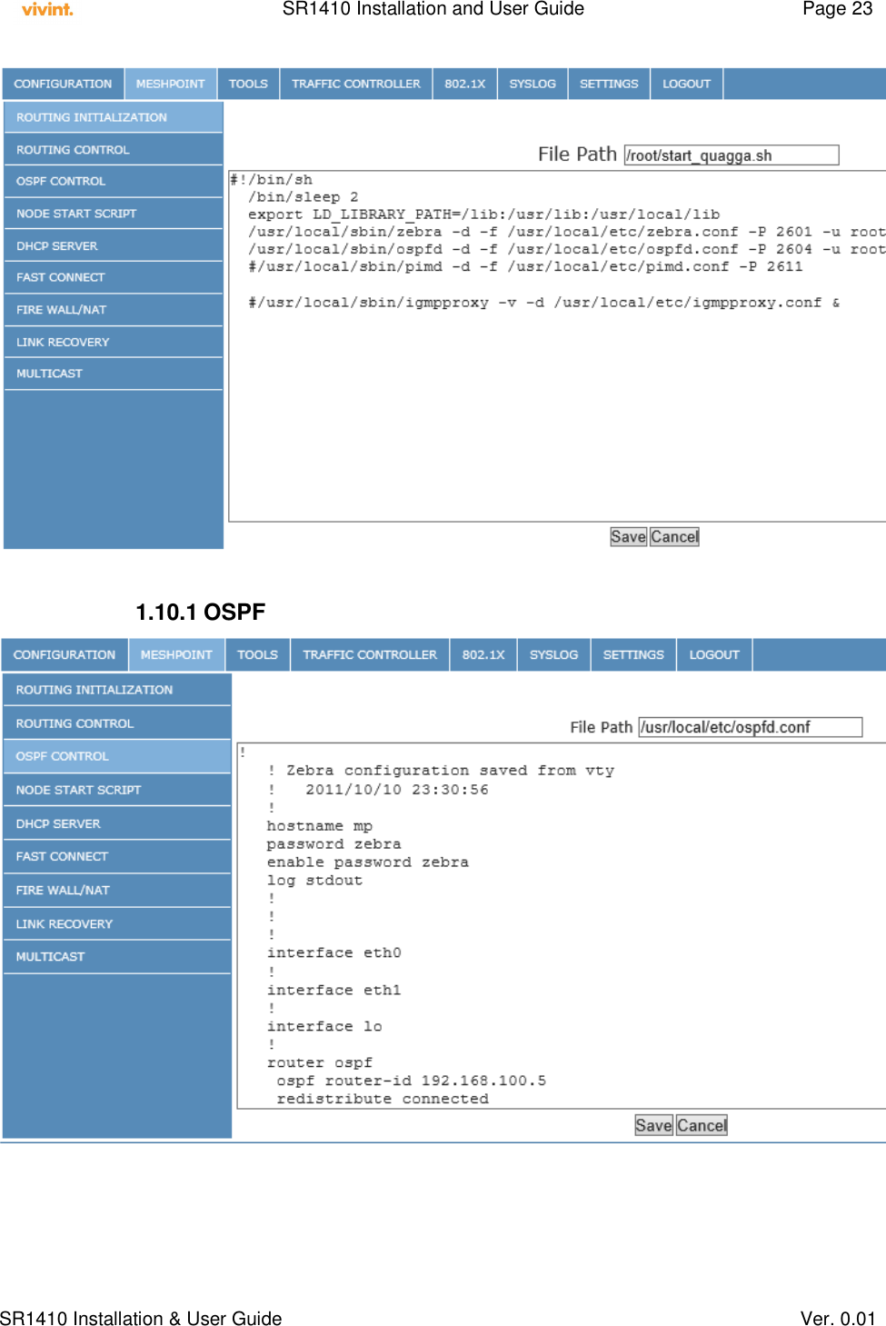
![SR1410 Installation and User Guide Page 5 SR1410 Installation & User Guide Ver. 0.01 Under Industry Canada regulations, this radio transmitter may only operate using an antenna of a type and maximum (or lesser) gain approved for the transmitter by Industry Canada. To reduce potential radio interference to other users, the antenna type and its gain should be so chosen that the equivalent isotropically radiated power (e.i.r.p.) is not more than that necessary for successful communication. Conformément à la réglementation d'Industrie Canada, le présent émetteur radio peut fonctionner avec une antenne d'un type et d'un gain maximal (ou inférieur) approuvé pour l'émetteur par Industrie Canada. Dans le but de réduire les risques de brouillage radioélectrique à l'intention des autres utilisateurs, il faut choisir le type d'antenne et son gain de sorte que la puissance isotrope rayonnée équivalente (p.i.r.e.) ne dépasse pas l'intensité nécessaire à l'établissement d'une communication satisfaisante. This radio transmitter SR1410 [or IC number if desired] has been approved by Industry Canada to operate with the antenna types listed below with the maximum permissible gain and required impedance for each antenna type indicated. Antenna types not included in this list, having a gain greater than the maximum gain indicated for that type, are strictly prohibited for use with this device. Cet émetteur radio SR1410 [or IC number if desired] a été approuvé par Industrie Canada pour fonctionner avec les types d'antennes énumérés ci-dessous avec le gain maximal admissible et l'impédance requis pour chaque type d'antenne indiqué. Types d'antennes ne figurent pas dans cette liste, ayant un gain supérieur au gain maximum indiqué pour ce type sont strictement interdits pour une utilisation avec cet appareil. This device complies with Industry Canada license-exempt RSS standard(s). Operation is subject to the following two conditions: (1) this device may not cause interference, and (2) this device must accept any interference, including interference that may cause undesired operation of the device. Le présent appareil est conforme aux CNR d'Industrie Canada applicables aux appareils radio exempts de licence. L'exploitation est autorisée aux deux conditions suivantes: (1) l'appareil ne doit pas produire de brouillage, et (2) l'utilisateur de l'appareil doit accepter tout brouillage radioélectrique subi, même si le brouillage est susceptible d'en compromettre le fonctionnement. The manual must provide the maximum antenna gain permitted for devices in the bands 5250-5350MHz and 5470-5725MHz. High power radars are allocated as primary users (meaning they have priority) in the 5250MHz to 5350MHz and 5650MHz to 5850MHz bands. These radars could cause interference and/or damage to Wireless LAN devices used in Canada. Les utilisateurs de radars de haute puissance sont désignés utilisateurs principaux (c.-à-d., qu’ils ont la priorité) pour les bandes 5 250 - 5 350 MHz et 5 650 - 5 850 MHz. Ces radars pourraient causer du brouillage et/ou des dommages aux dispositifs LAN-EL.](https://usermanual.wiki/Vivint/SR1410.professional-installation-manua/User-Guide-2039681-Page-5.png)


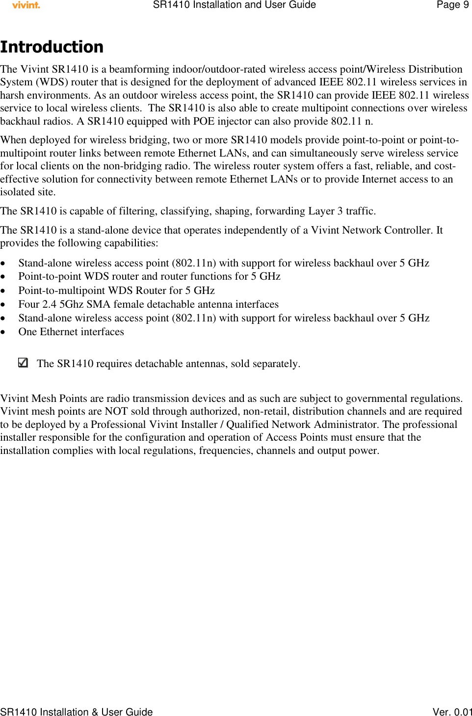


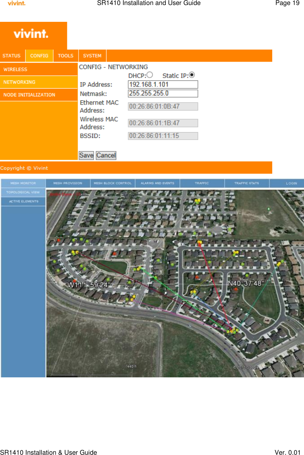
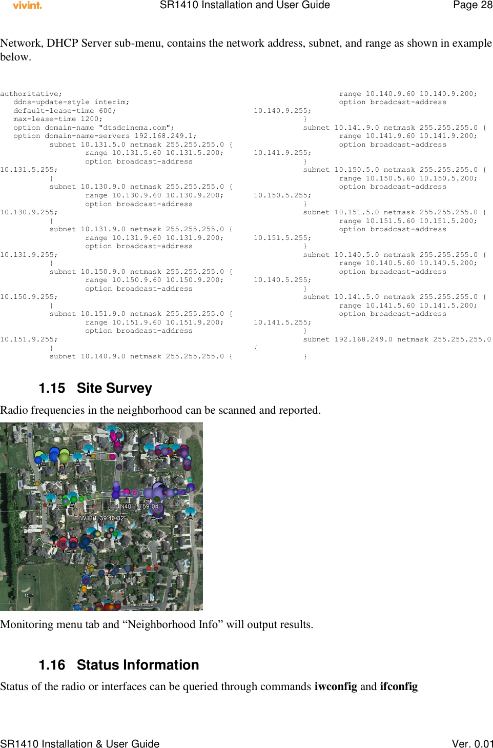
![SR1410 Installation and User Guide Page 21 SR1410 Installation & User Guide Ver. 0.01 The Hierarchical Token Bucket[HTB] creates a hierarchy of software queues called qdiscs which represent the flow of traffic on a network interface. A parent (base) qdisc can have multiple child qdiscs which in turn can be parents to other qdiscs. A leaf qdisc is the one which has no children. The HTB is a classfull qdisc which means that traffic flowing through the interface can be classified into flows. The classification can be performed using various filters assigned to the qdisc. The parameter "rate" in the above command specifies the base or guaranteed bit rate of the qdisc corresponding to the class. The parameter burst corresponds to the amount of data in bytes that will be processed at a time for that qdisc. For an ingress qdisc it represents the bytes send up to the network stack for processing. For an egress qdisc it represents the amount of data sent to the hardware for transmitting out. The parameter "ceil" or ceiling represents the maximum bit rate for the qdisc. HTB qdiscs have the capability to borrow bandwidth from peers which will be explained in the subsequent sections. Example: tc class add dev eth0 parent 1:1 classid 1:10 htb rate 50mbit burst 1mbit ceil 60mbit tc class add dev eth0 parent 1:1 classid 1:11 htb rate 20mbit burst 1mbit ceil 40mbit The above commands create qdiscs of class labeled "1:10" and "1:11" for the qdisc "1:1". The parameter "rate" represents the guaranteed or base bit rate for the qdiscs. The parameter "burst" is the amount of data transmitted/received for the qdisc in a given time period. The parameter "ceil" is the maximum bit rate for the qdisc. As mentioned before peer qdiscs can borrow bandwidth from each other if one of the qdiscs is using less than base bandwidth or there is unused bandwidth available. Suppose qdisc 1:10 uses 50mbits but requires a total of 60mbps due to the bandwidth intensive nature of the application.. On the other hand class 1:11 is using 10mbits out of the assigned 20mbits base bandwidth. In this case class 1:10 can borrow the additional 10mbps from 1:11 and use up its maximum assigned bandwidth of 60mbps.](https://usermanual.wiki/Vivint/SR1410.professional-installation-manua/User-Guide-2039681-Page-21.png)
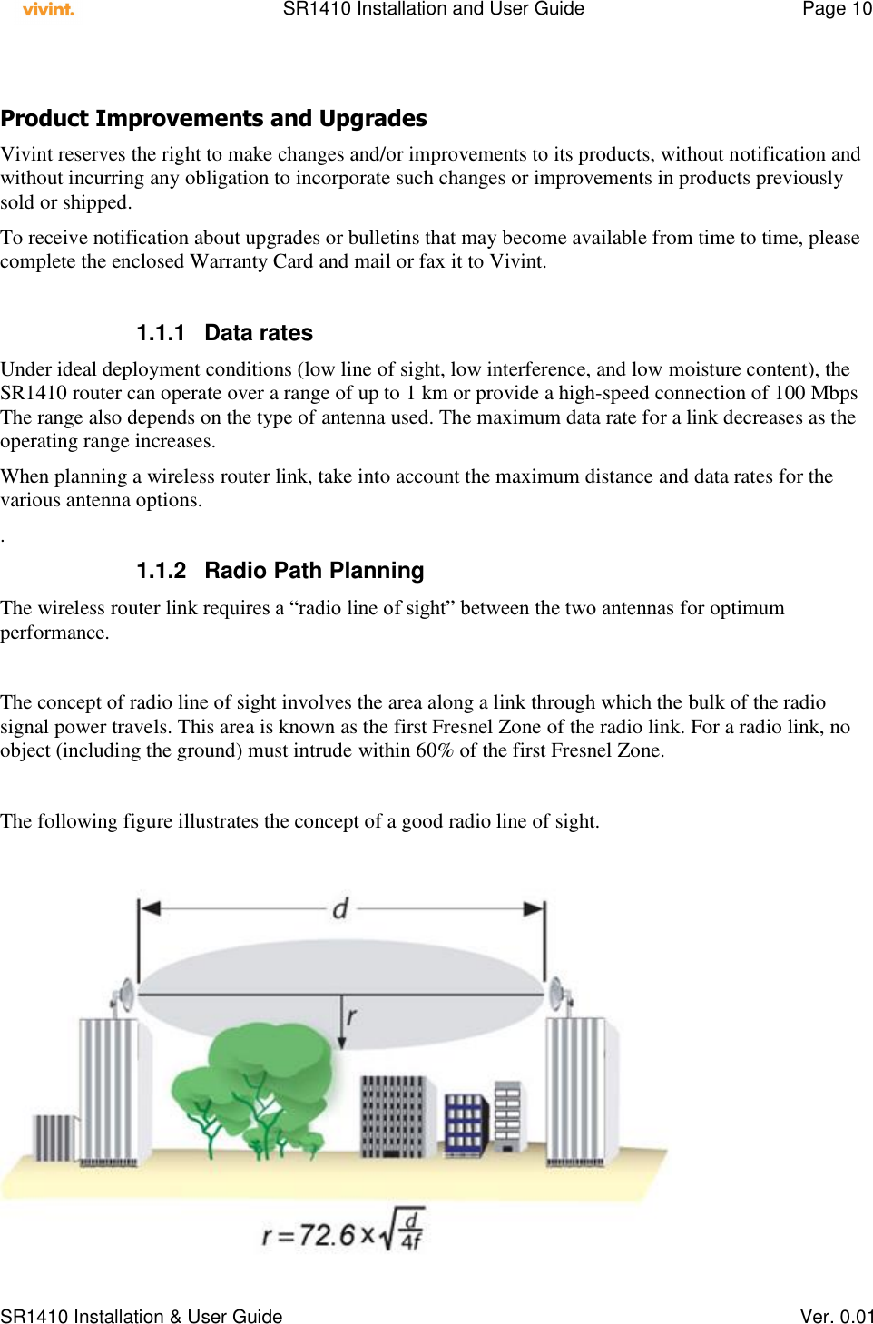
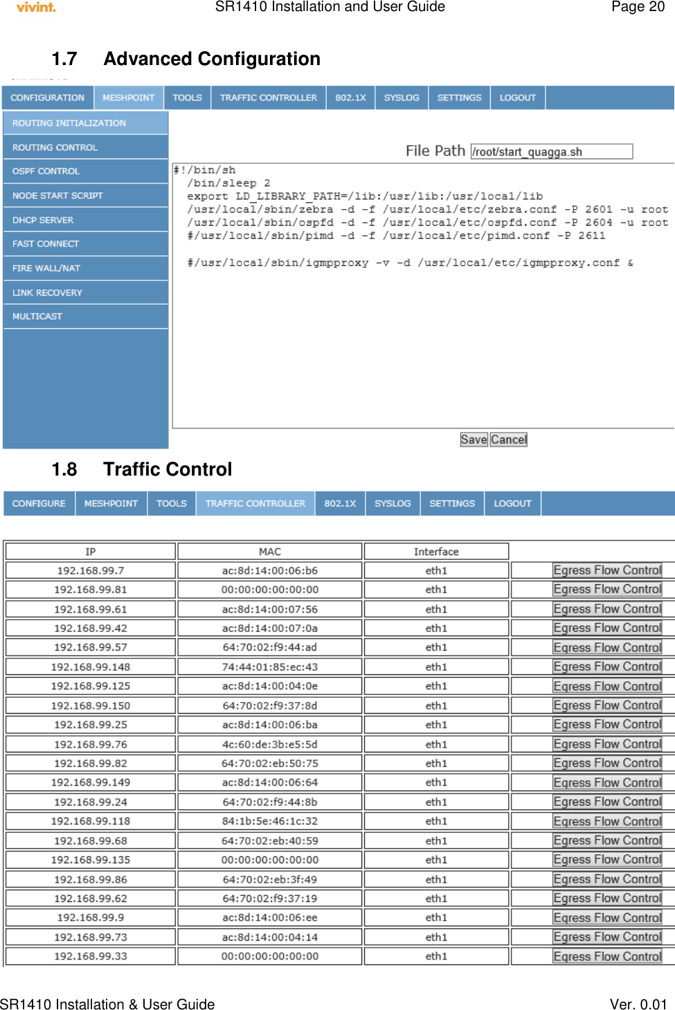
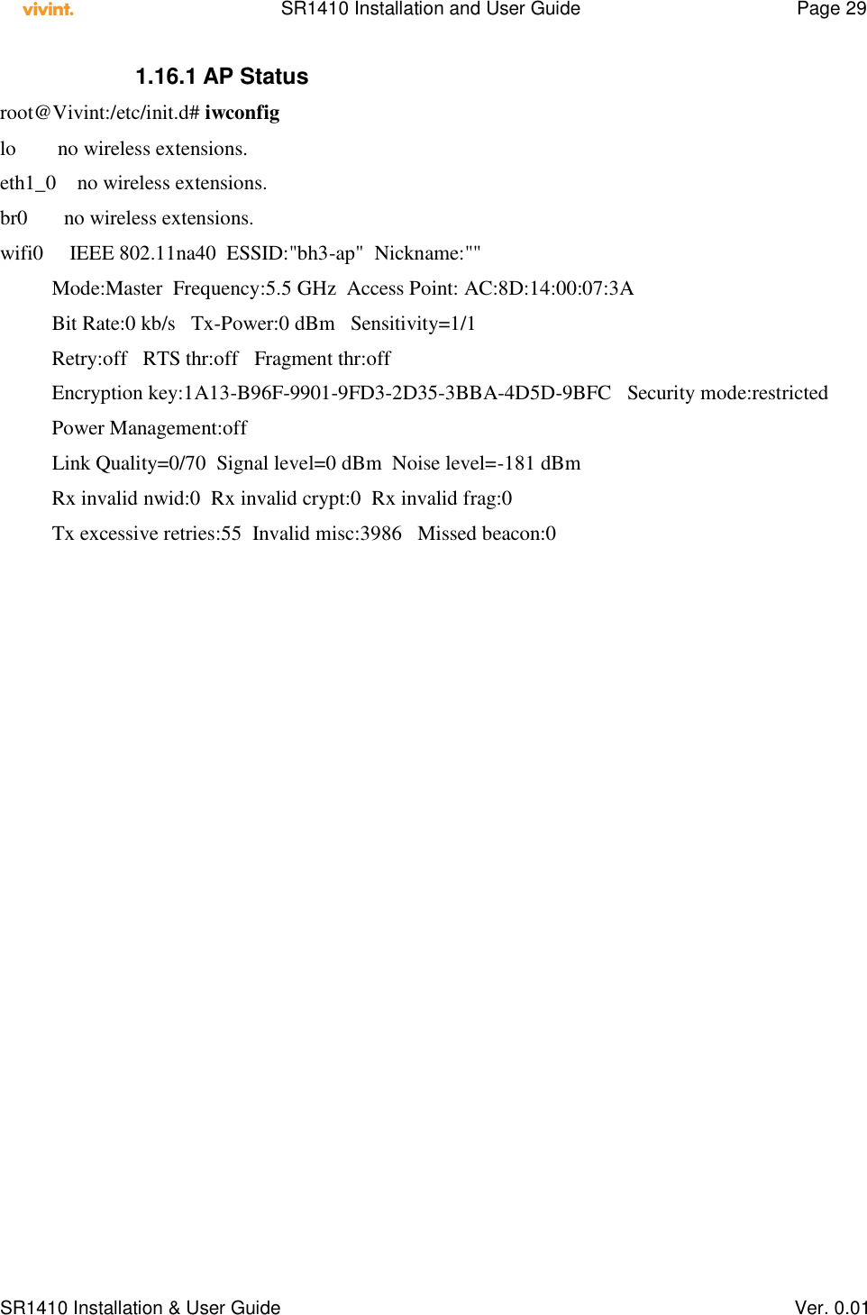
![SR1410 Installation and User Guide Page 24 SR1410 Installation & User Guide Ver. 0.01 Example: ! ! Zebra configuration saved from vty - zebra.conf ! 2009/07/10 23:30:56 ! hostname mpp password mysecret enable password mysecret ! interface eth0 link-detect multicast ! interface eth1 link-detect multicast ! interface lo ! interface ra_sta0 link-detect multicast ! interface ra_sta1 link-detect multicast ! interface ra_ap0 link-detect multicast ! interface ra_ap1 link-detect multicast ! ip forwarding ipv6 forwarding ! ! line vty ! ! ! Zebra configuration saved from vty – ospfd.conf ! 2009/07/10 23:36:59 ! hostname mpp password mysecret enable password mysecret log stdout ! ! ! interface eth0 ! interface eth1 ! interface lo ! interface ra_sta0 ! interface ra_sta1 ! interface ra_ap0 ! interface ra_ap1 ! router ospf ospf router-id 192.168.249.5 redistribute connected network 192.168.249.0/24 area 0.0.0.0 network 10.131.5.0/24 area 0.0.0.0 network 10.15.0.0/24 area 0.0.0.0 network 10.17.0.0/24 area 0.0.0.0 network 10.130.9.0/24 area 0.0.0.0 network 10.131.9.0/24 area 0.0.0.0 ! line vty ! For each of the networks present at the mesh router, a line is inserted to instruct the OSPF protocol to advertise the routes to its neighbor/s. 1.10.2 RIP Distance vector Routing Information Protocol[RIP] configuration file is located at /usr/local/etc/ripd.conf 1.10.3 IGMP Internet Group Management Protocol[IGMP] configuration file is located at /usr/local/etc/igmpd.conf 1.10.4 PIM Protocol Independent Multicast[PIM] configuration is located at /usr/local/etc/pimd.conf 1.10.5 BGP Border Gateway Protocol [BGP] configuration is located at /usr/local/etc/bgpd.conf 1.11 Multicast Control Multicast servers and clients can be on any of the node interfaces. To provision multicast rules, the source and destination of the stream and the multicast address on which the stream flows needs to be identified. The screen below shows a typical multicast configuration.](https://usermanual.wiki/Vivint/SR1410.professional-installation-manua/User-Guide-2039681-Page-24.png)
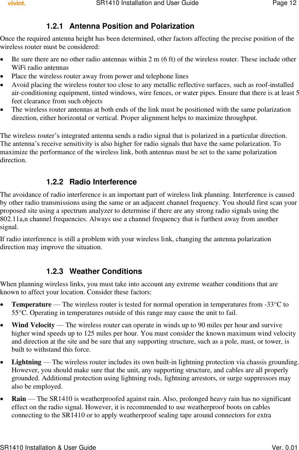
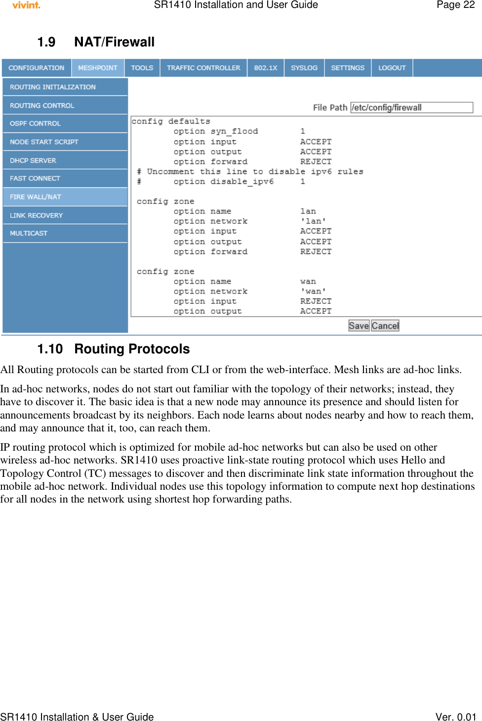
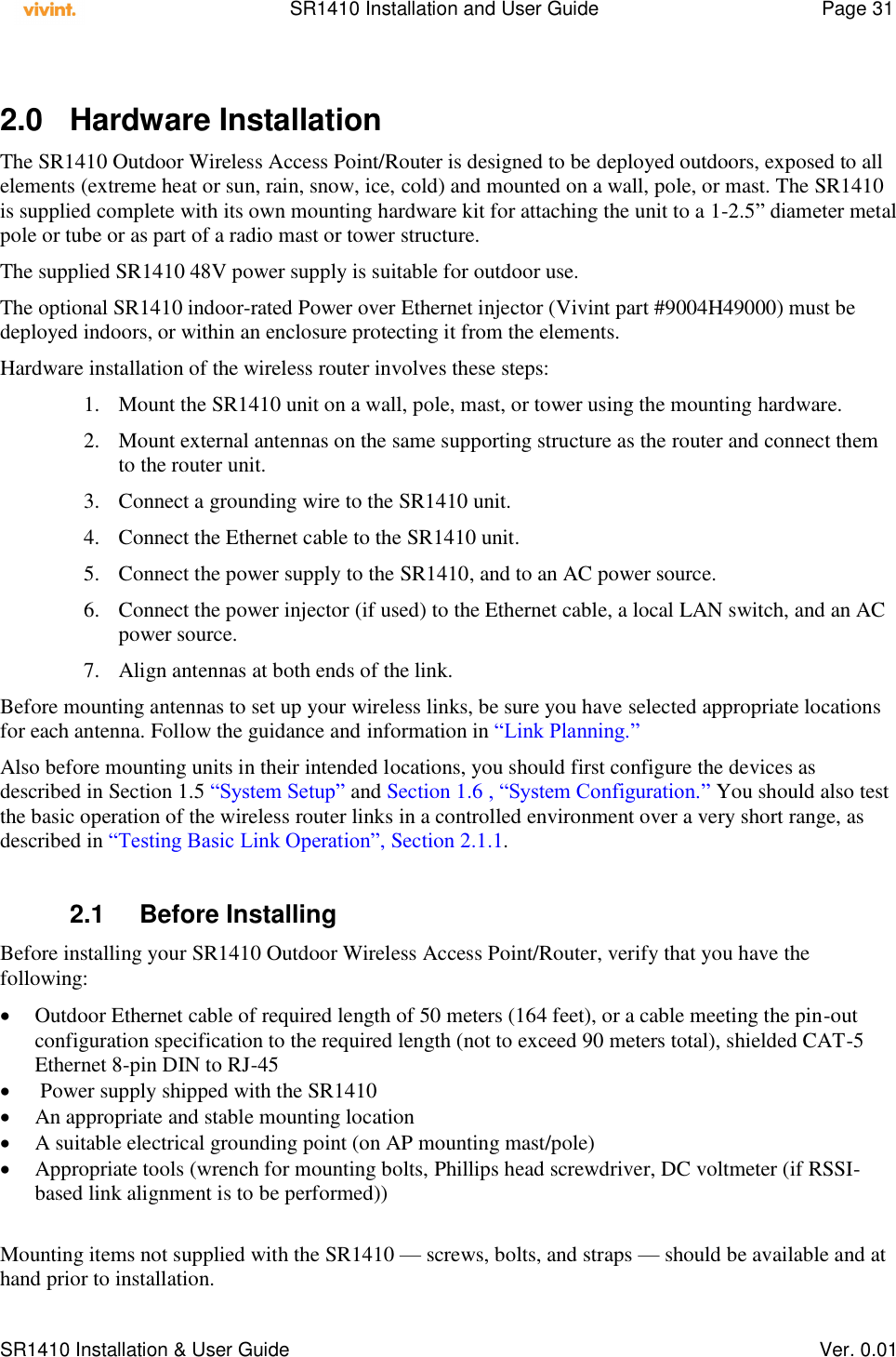
![SR1410 Installation and User Guide Page 25 SR1410 Installation & User Guide Ver. 0.01 Example: To enable multicast flows from 192.168.1.92 [attached on the wired segment – eth0] IGMP multimedia server, to all wireless [ra_ap0] clients who are recipients, insert a rule as shown. There can be multiple rules and these rules are launched upon restart of mesh router. Upon provisioning the multicast rule, the node boot script is updated. The multicast rules take affect upon reboot of the node. The boot script shown below illustrates the rule entry. 1.12 Administration 1.12.1 Adding Users & Changing Password Usage: adduser [OPTIONS] user_name Add an user Options: -h DIR Home directory -g GECOS GECOS field -s SHELL Login shell -G GROUP Add user to existing group -S Create a system user -D Do not assign a password -H Do not create home directory Usage: passwd Change password of an user 1.12.2 Upgrading Firmware The System Reset directly resets the microprocessor and the on-board flash memory (as opposed to the Compact Flash memory). Assertion of the System Reset causes an IO Reset to be asserted. The System Reset is asserted by any of the following conditions: An assertion of the Power-On Reset A press of the reset button A watchdog timeout](https://usermanual.wiki/Vivint/SR1410.professional-installation-manua/User-Guide-2039681-Page-25.png)
![SR1410 Installation and User Guide Page 26 SR1410 Installation & User Guide Ver. 0.01 1.13 System Log /var/log/message keeps a circular log in memory, no filesystem activity involved. 1.13.1 Enabling System Logging To read the logfile from syslogd you should use the logread command, which outputs the messages in syslogd's circular buffer. Logging is always enabled. 1.14 DHCP Configuration The SR1410 can be configured as a controller less Mesh Point Portal [MPP] or a controller based Mesh Point [MP]. When configured as MPP, the DHCP addresses are allocated by the node itself. The DHCP Directives in the main configuration screen drive the behavior of the mesh node. Normally, the dhcp server running on the network manager serves all the clients connecting to the nodes within a mesh block. The dhcp server needs to be aware of the subnets at the mesh node access points and be able to assign dynamic addresses based on those subnets. The dhcp server shall assign a common dns server to all the clients within the mesh block. The dhcp server shall be aware of the mesh node access point IP address from which the dhcp lease request is received for a client. This AP address is the default router which shall be assigned to the client requesting dhcp lease. The Mesh block network topology comprises several nodes and each node may have an AP within a subnet different from that of the DHCP interface. It is therefore necessary that the DHCP server detect the subnet of the AP from which the DHCP request was originally received on behalf of a client. Once it has the subnet information of this AP, it should assign the requesting client an IP address within the same subnet as the AP. The SR1410 can also be operated an MP where it relies on the network manager to allocate DHCP addresses. On the other hand, it can also act as a DHCP server for a cluster of MPs. The node that is elected to run DHCP service is the MPP.](https://usermanual.wiki/Vivint/SR1410.professional-installation-manua/User-Guide-2039681-Page-26.png)


![SR1410 Installation and User Guide Page 34 SR1410 Installation & User Guide Ver. 0.01 Point-to-Point Configurations – In a point-to-point configuration, the alignment process requires two people at each end of the link. The use of cell phones or two-way radio communication may help with coordination. To start, you can just point the antennas at each other, using binoculars or a compass to set the general direction. For accurate alignment, you must set the transmitter to output in continuous transmit mode, and set the receiver to be in continuous receive frame mode. As the antenna moves horizontally and vertically, the RSSI values vary and are indicated on the management interface. Point-to-Multipoint Configurations – In a point-to-multipoint configuration all Slave routers must be aligned with the Master router antenna. The alignment process is the same as in point-to-point links, but only the Slave end of the link requires the alignment. Steps for aligning antenna: Initialize the transmitting radio to be in continuous transmit mode. The interface shall be enabled at the main screen as shown below, by selecting the red rectangle on mouse-over 2.4 Command Line Interface Commands that perform the most functions are: ifconfig – Network related iwpriv – WLAN related iwconfig – WLAN related iptables – Traffic filter, classification, forwarding, NAT tc – traffic queuing 2.4.1 Getting Help on CLI Commands 2.4.1.1 ifconfig root@Vivint:~# ifconfig --help BusyBox v1.11.2 (2010-08-07 08:17:48 PDT) multi-call binary Usage: ifconfig [-a] interface [address] Configure a network interface Options: [add ADDRESS[/PREFIXLEN]] [del ADDRESS[/PREFIXLEN]] [[-]broadcast [ADDRESS]] [[-]pointopoint [ADDRESS]] [netmask ADDRESS] [dstaddr ADDRESS] [hw ether ADDRESS] [metric NN] [mtu NN]](https://usermanual.wiki/Vivint/SR1410.professional-installation-manua/User-Guide-2039681-Page-34.png)
![SR1410 Installation and User Guide Page 35 SR1410 Installation & User Guide Ver. 0.01 [[-]trailers] [[-]arp] [[-]allmulti] [multicast] [[-]promisc] [txqueuelen NN] [[-]dynamic] [up|down] ... 2.4.1.2 iwpriv root@Vivint:~# iwpriv --help Usage: iwpriv interface [private-command [private-arguments]] 2.4.1.3 iptables root@Vivint:~# iptables --help iptables v1.4.0 Usage: iptables -[AD] chain rule-specification [options] iptables -[RI] chain rulenum rule-specification [options] iptables -D chain rulenum [options] iptables -[LFZ] [chain] [options] iptables -[NX] chain iptables -E old-chain-name new-chain-name iptables -P chain target [options] iptables -h (print this help information) Commands: Either long or short options are allowed. --append -A chain Append to chain --delete -D chain Delete matching rule from chain --delete -D chain rulenum Delete rule rulenum (1 = first) from chain --insert -I chain [rulenum] Insert in chain as rulenum (default 1=first) --replace -R chain rulenum Replace rule rulenum (1 = first) in chain --list -L [chain] List the rules in a chain or all chains --flush -F [chain] Delete all rules in chain or all chains --zero -Z [chain] Zero counters in chain or all chains --new -N chain Create a new user-defined chain --delete-chain](https://usermanual.wiki/Vivint/SR1410.professional-installation-manua/User-Guide-2039681-Page-35.png)
![SR1410 Installation and User Guide Page 36 SR1410 Installation & User Guide Ver. 0.01 -X [chain] Delete a user-defined chain --policy -P chain target Change policy on chain to target --rename-chain -E old-chain new-chain Change chain name, (moving any references) Options: --proto -p [!] proto protocol: by number or name, eg. `tcp' --source -s [!] address[/mask] source specification --destination -d [!] address[/mask] destination specification --in-interface -i [!] input name[+] network interface name ([+] for wildcard) --jump -j target target for rule (may load target extension) --goto -g chain jump to chain with no return --match -m match extended match (may load extension) --numeric -n numeric output of addresses and ports --out-interface -o [!] output name[+] network interface name ([+] for wildcard) --table -t table table to manipulate (default: `filter') --verbose -v verbose mode --line-numbers print line numbers when listing --exact -x expand numbers (display exact values) [!] --fragment -f match second or further fragments only --modprobe=<command> try to insert modules using this command --set-counters PKTS BYTES set the counter during insert/append [!] --version -V print package version 2.4.1.4 tc root@Vivint:~# tc Usage: tc [ OPTIONS ] OBJECT { COMMAND | help }](https://usermanual.wiki/Vivint/SR1410.professional-installation-manua/User-Guide-2039681-Page-36.png)
![SR1410 Installation and User Guide Page 37 SR1410 Installation & User Guide Ver. 0.01 tc [-force] -batch file where OBJECT := { qdisc | class | filter | action | monitor } OPTIONS := { -s[tatistics] | -d[etails] | -r[aw] | -b[atch] [file] } 2.4.1.5 iwconfig root@Vivint:~# iwconfig --help Usage: iwconfig [interface] interface essid {NNN|any|on|off} interface mode {managed|ad-hoc|master|...} interface freq N.NNN[k|M|G] interface channel N interface bit {N[k|M|G]|auto|fixed} interface rate {N[k|M|G]|auto|fixed} interface enc {NNNN-NNNN|off} interface key {NNNN-NNNN|off} interface power {period N|timeout N|saving N|off} interface nickname NNN interface nwid {NN|on|off} interface ap {N|off|auto} interface txpower {NmW|NdBm|off|auto} interface sens N interface retry {limit N|lifetime N} interface rts {N|auto|fixed|off} interface frag {N|auto|fixed|off} interface modulation {11g|11a|CCK|OFDMg|...} interface commit 3.0 Specifications 3.1 Product features Wireless accesspoint and station Various antenna options Protocol-independent networking functionality Supports IEEE 802.11n, 40Mhz operation as an AP Supports IEEE 802.11n, 40 Mhz operation as an STA Seamless connectivity to wired LANs augment existing networks quickly and easily](https://usermanual.wiki/Vivint/SR1410.professional-installation-manua/User-Guide-2039681-Page-37.png)