Vocollect TAP700-01 Vocollect T5 TAP700-01 Voice-Enabled Device with Wireless Capability User Manual CERTIFICATE OF COMPLIANCE
Vocollect Inc Vocollect T5 TAP700-01 Voice-Enabled Device with Wireless Capability CERTIFICATE OF COMPLIANCE
User Manual
Rhein Tech Laboratories, Inc. Client: Vocollect, Inc.
360 Herndon Parkway Model #: TAP700-01
Suite 1400 Standards: FCC 15.247 & RSS-210
Herndon, VA 20170 ID’s: MQO-TAP700-01/2570A-TAP70001
http://www.rheintech.com Report #: 2012302DSS
Appendix K: Manual
Please refer to the following pages.

Vocollect Hardware Reference
September 2012
ETP.HW.4100.2012.09

Notice
About Vocollect Documentation
©1987-2012 Vocollect. All rights reserved.
Vocollect
703 Rodi Road
Pittsburgh, PA 15235-4558
Phone: 412-829-8145
Fax: 412-829-0972
http://www.vocollect.com
Trademark
Vocollect product and company names, as well as their respective logos are trademarks or registered
trademarks of Vocollect.
All other product names mentioned herein are trademarks or registered trademarks of their respective
owners.
Confidentiality
This documentation provides information for Vocollect customers who are using Vocollect hardware.
For use by employees, partners, and customers of Vocollect. All equipment design and technical
information contained within this document is the confidential property of Vocollect. No use or disclosure
thereof may be made without written permission from Vocollect.
Warning and Disclaimer
Vocollect has carefully checked the information in this documentation and believes it to be accurate.
However, Vocollect assumes no responsibility for any inaccuracies that this documentation may contain.
In no event will Vocollect be liable for direct, indirect, special, exemplary, incidental, or consequential
damages resulting from any defect or omission in this system, even if advised of the possibility of such
damages.
In the interest of product development, Vocollect reserves the right to make improvements to the
information in this documentation and the products that it describes at any time, without notice or
obligation.
Confidential: For informational use by Vocollect Resellers and customers only

Contents
Chapter 1: Introduction.................................................................................15
General Safety Guidelines...........................................................................................................................15
Vocollect Battery Safety....................................................................................................................16
Cleaning Procedures for Vocollect Equipment............................................................................................17
Cleaning Plastics................................................................................................................................17
Cleaning Contacts..............................................................................................................................17
Contact Information.....................................................................................................................................18
Patents and Intellectual Property...............................................................................................................19
Chapter 2: Talkman Devices and Headsets...............................................21
Turning a Talkman Device On.....................................................................................................................22
Turning a Talkman Device Off....................................................................................................................22
Loading an Operator's Templates................................................................................................................23
Adjusting the Voice.......................................................................................................................................24
Adjusting the Pitch............................................................................................................................24
Adjusting the Volume Using Voice...................................................................................................24
Adjusting the Volume Using Device Buttons...................................................................................25
Adjusting the Speed...........................................................................................................................25
Changing the Speaker's Gender........................................................................................................25
Understanding Talkman Commands..........................................................................................................26
Part Numbers: Vocollect Talkman Devices.................................................................................................26
Part Numbers: Talkman Accessories...........................................................................................................26
Choosing the Right Headset.........................................................................................................................27
Part Numbers: Wired Headsets...................................................................................................................28
Part Numbers: Wired Headset Accessories.................................................................................................29
Part Numbers: Wireless Headsets...............................................................................................................31
Part Numbers: Wireless Headset Accessories............................................................................................31
Part Numbers: Chargers..............................................................................................................................32
Chapter 3: Talkman A500...............................................................................35
A500 Specifications.......................................................................................................................................35
Charging an A500 or T5 Device...................................................................................................................36
A500/T5 High-Performance Batteries Specifications......................................................................36
Charging an A500 or T5 Battery in a Device...................................................................................37
Charging an A500 or T5-Series Battery...........................................................................................37
Removing an A500, T2-Series or T5-Series Device From a Charger..............................................38
Inserting a Battery into a Talkman A500, T5-Series or T2-Series Device.....................................38
Removing a Battery from a Talkman A500, T5-Series or T2-Series Device..................................39
Confidential: For informational use by Vocollect Resellers and customers only
Contents | 5

Battery Warm-Up Time.....................................................................................................................39
About LED Indicators...................................................................................................................................40
A500 Device LED Indicators.............................................................................................................40
Pairing an A500 or T5 Device and a Bluetooth Device...............................................................................41
Pairing with the Honeywell MS9535: Talkman Device Is the Initiator.........................................41
Pairing with the Honeywell MS9535: Talkman Device Is the Acceptor.........................................41
Pairing with Zebra QL Series Printers.............................................................................................41
Pairing with Intermec PB50 Printers...............................................................................................42
Pairing the Honeywell LXE 8652 Scanner: Talkman Device Is the Initiator................................42
Pairing the Honeywell LXE 8652 Scanner: Scanner Is the Initiator.............................................43
Pairing the Socket Cordless Ring Scanner with a Talkman T5......................................................44
Installing an A500 or T5-Series Device Into a Vehicle...............................................................................44
Talkman A500/T5 VMT Mobile Computer Accessories...................................................................45
Talkman A500/T5 VMT Mobile Computer Accessory Specifications..............................................46
Mounts for Talkman A500/T5 VMT Mobile Computers..................................................................46
Positioning the Talkman A500/T5 VMT Mobile Computer.............................................................47
Installing the Mounting Brackets for a Talkman A500/T5 VMT Mobile Device...........................47
Connecting Cables to the Power Supply and Attaching the Power Supply to a Vehicle...............48
Connecting the Talkman A500/T5 VMT Mobile Computer to a Vehicle's Power Source..............50
Removal of Talkman A500/T5 VMT Mobile Computer from Vehicle.............................................51
Accessories....................................................................................................................................................51
Pidion BM-170 Display......................................................................................................................52
T5/A500 Adjustable Shoulder Harness.............................................................................................54
Belts and Belt Clips...........................................................................................................................55
Device Covers.....................................................................................................................................56
Chapter 4: Talkman T5 Series......................................................................59
T5-Series Specifications: Talkman T5 and Talkman T5m.........................................................................59
Charging an A500 or T5 Device...................................................................................................................60
A500/T5 High-Performance Batteries Specifications......................................................................61
Charging an A500 or T5 Battery in a Device...................................................................................61
Charging an A500 or T5-Series Battery...........................................................................................62
Removing an A500, T2-Series or T5-Series Device From a Charger..............................................62
Inserting a Battery into a Talkman A500, T5-Series or T2-Series Device.....................................62
Removing a Battery from a Talkman A500, T5-Series or T2-Series Device..................................63
Battery Warm-Up Time.....................................................................................................................64
About LED Indicators...................................................................................................................................64
T5-Series Device LED Indicators......................................................................................................64
Pairing an A500 or T5 Device and a Bluetooth Device...............................................................................65
Pairing with the Honeywell MS9535: Talkman Device Is the Initiator.........................................65
Pairing with the Honeywell MS9535: Talkman Device Is the Acceptor.........................................66
Pairing with Zebra QL Series Printers.............................................................................................66
Pairing with Intermec PB50 Printers...............................................................................................66
Pairing the Honeywell LXE 8652 Scanner: Talkman Device Is the Initiator................................66
Confidential: For informational use by Vocollect Resellers and customers only
6| Vocollect Hardware Documentation

Pairing the Honeywell LXE 8652 Scanner: Scanner Is the Initiator.............................................67
Pairing the Socket Cordless Ring Scanner with a Talkman T5......................................................68
Installing an A500 or T5-Series Device Into a Vehicle...............................................................................69
Talkman A500/T5 VMT Mobile Computer Accessories...................................................................69
Talkman A500/T5 VMT Mobile Computer Accessory Specifications..............................................70
Mounts for Talkman A500/T5 VMT Mobile Computers..................................................................71
Positioning the Talkman A500/T5 VMT Mobile Computer.............................................................71
Installing the Mounting Brackets for a Talkman A500/T5 VMT Mobile Device...........................71
Connecting Cables to the Power Supply and Attaching the Power Supply to a Vehicle...............72
Connecting the Talkman A500/T5 VMT Mobile Computer to a Vehicle's Power Source..............74
Removal of Talkman A500/T5 VMT Mobile Computer from Vehicle.............................................75
Accessories....................................................................................................................................................76
T5/A500 Adjustable Shoulder Harness.............................................................................................76
Belts and Belt Clips...........................................................................................................................77
Device Covers.....................................................................................................................................78
Chapter 5: Talkman T2 Series......................................................................81
T2 Series Specifications: Talkman T2x and Talkman T2..........................................................................81
Charging a T2-Series Device........................................................................................................................82
T2 Series High Capacity Battery Specifications..............................................................................82
Charging a T2 Series Device.............................................................................................................83
Removing an A500, T2-Series or T5-Series Device From a Charger..............................................84
Inserting a Battery into a Talkman A500, T5-Series or T2-Series Device.....................................84
Removing a Battery from a Talkman A500, T5-Series or T2-Series Device..................................85
Battery Warm-Up Time.....................................................................................................................86
About LED Indicators...................................................................................................................................86
T2-Series Device LED Indicators......................................................................................................86
Connecting a T2-Series with the Honeywell MS9535................................................................................87
Accessories....................................................................................................................................................87
Belts and Belt Clips...........................................................................................................................88
Device Covers.....................................................................................................................................89
Chapter 6: Talkman T1...................................................................................91
T1 Specifications: Talkman T1....................................................................................................................91
Charging the T1............................................................................................................................................92
T1 Batteries Specifications................................................................................................................92
Charging a T1 Battery in a Device...................................................................................................92
Charging a T1 Battery in a T1 10-Bay Combination Charger........................................................93
Charging a T1 Battery with a T1 Single Charger Cable.................................................................93
Removing a T1 Device From a T1 10-Bay Combination Charger...................................................93
Disconnecting a T1 Device from a T1 Single Charger Cable...........................................................93
Inserting a Battery into a Talkman T1 Device................................................................................93
Removing a Battery from a Talkman T1 Device..............................................................................94
Confidential: For informational use by Vocollect Resellers and customers only
Contents | 7

Battery Warm-Up Time.....................................................................................................................94
About LED Indicators...................................................................................................................................94
T1 Device LED Indicators.................................................................................................................94
Accessories....................................................................................................................................................95
T1 Holster...........................................................................................................................................96
Chapter 7: Vocollect Wired Headsets..........................................................99
SL-4 and SL-14 Vocollect Light Industrial Behind-the-Head Headset.....................................................99
SL-14 Headset Specifications..........................................................................................................100
SL-4 Headset Specifications............................................................................................................101
Wearing the SL-14 or SL-4 Behind-the-Head Headset.................................................................101
Proper Use and Care Instructions for Talkman T1 and SL-4/SL-14 Headsets............................101
SR-10 and SR-15 Vocollect Behind-the-Head Headset.............................................................................103
SR-15 Headset Specifications..........................................................................................................103
Wearing the SR-15 Behind-the-Head Headset..............................................................................104
Removing the SR-15 Headset Adjustment Strap ..........................................................................104
Attaching the SR-15 Headset Adjustment Strap...........................................................................105
Replacing the Ear Pad on the SR-15 Headset................................................................................105
SR-20-Series Vocollect Lightweight Headset............................................................................................105
SR-20 Headset Specifications..........................................................................................................105
SR-21 Headset Specifications..........................................................................................................106
Replacing the Ear Pad on the SR-20 Series Headsets ..................................................................106
SR-30 Vocollect High-Noise Headset.........................................................................................................107
SR-30 Headset Specifications..........................................................................................................107
SR-31 Headset Specifications..........................................................................................................107
SR-35 Vocollect Hard-Hat Headset...........................................................................................................108
SR-35 Headset Specifications..........................................................................................................108
SR-40 Vocollect Dual-Cup Headset...........................................................................................................109
SR-40 Headset Specifications..........................................................................................................109
Care and Use of Headsets and Microphones.............................................................................................109
Wearing Headsets: General Procedures.........................................................................................110
Adjusting Headsets for Comfort......................................................................................................110
Removing Headsets.........................................................................................................................111
Cleaning Windscreens.....................................................................................................................111
Cleaning Headsets...........................................................................................................................112
Chapter 8: Vocollect Wireless Headsets...................................................113
Vocollect SRX Wireless Headset................................................................................................................114
SRX Wireless Headset Specifications.............................................................................................114
Charging the SRX Headset.............................................................................................................115
Installing the SRX Mobility Strap..................................................................................................117
Wearing an SRX Wireless Headset.................................................................................................118
Headset Functions and LED Patterns for SRX..............................................................................119
Confidential: For informational use by Vocollect Resellers and customers only
8| Vocollect Hardware Documentation

Vocollect SRX2 Wireless Headset..............................................................................................................121
SRX2 Wireless Headset Specifications...........................................................................................122
SRX2 Modular Design.....................................................................................................................122
Attaching the SRX2 Electronics Module to a Headband...............................................................123
Removing the SRX2 Electronics Module from a Headband..........................................................124
SRX2 Compatibility.........................................................................................................................124
Charging the SRX2 Headset...........................................................................................................124
Wearing an SRX2 Wireless Headset...............................................................................................127
Headset Functions and LED Patterns for SRX2............................................................................130
About Pairing Wireless Headsets..............................................................................................................132
Pairing an SRX Headset..................................................................................................................133
Pairing an SRX2 Headset................................................................................................................135
Pairing a Headset by VoiceConsole Pairing...................................................................................137
More about SRX/SRX2 Pairing Modes............................................................................................138
Breaking a Pairing...........................................................................................................................139
Headset Pairing FAQ.......................................................................................................................139
Supervisor Audio with SRX/SRX2 Headsets.............................................................................................140
Configuration Parameters for SRX/SRX2 Headsets.................................................................................141
Care and Use of Headsets and Microphones.............................................................................................143
Wearing Headsets: General Procedures.........................................................................................143
Adjusting Headsets for Comfort......................................................................................................143
Removing Headsets.........................................................................................................................144
Cleaning Windscreens.....................................................................................................................144
Cleaning Headsets...........................................................................................................................145
Chapter 9: Chargers......................................................................................147
T5/A500 Combination Charger..................................................................................................................147
T5/A500 10-Bay Combination Charger Specifications..................................................................148
Easy Configuration..........................................................................................................................148
T5/A500 Combination Charger Power Supply Specifications.......................................................149
T5/A500 Combination Charger Wall Mount..................................................................................150
About LED Indicators......................................................................................................................151
T2 Series Battery Chargers........................................................................................................................152
T2 Series Battery Charger Specifications......................................................................................153
Assembling the Stands for the T2 Charger....................................................................................153
Charger Wall Mount, Multiple Chargers: T2 Series .....................................................................154
About LED Indicators......................................................................................................................158
T1 10-Bay Combination Charger...............................................................................................................159
T1 10-Bay Combination Charger Specifications............................................................................159
T1 10-Bay Combination Charger Power Supply Specifications....................................................160
T1 10-Bay Combination Charger Wall Mount...............................................................................160
T1 Single Charger Cable............................................................................................................................163
T1 Single Charger Cable Specifications.........................................................................................163
T1 Single Charger Cable Power Supply Specifications.................................................................163
Confidential: For informational use by Vocollect Resellers and customers only
Contents | 9

SRX Headset Battery Charger...................................................................................................................164
SRX Headset Battery Charger Specifications................................................................................164
SRX Battery Charger Wall Mount..................................................................................................165
SRX2 Headset Battery Charger.................................................................................................................167
SRX2 Headset Battery Charger Specifications..............................................................................167
SRX2 Battery Charger Wall Mount................................................................................................168
About LED Indicators......................................................................................................................170
Chapter 10: Bar Code Readers and Printers...........................................173
Intermec SF51 Cordless Scanner...............................................................................................................174
Pairing the Intermec SF51 Scanner: Device Is the Initiator........................................................174
Pairing the Intermec SF51 Scanner: Scanner Is the Initiator......................................................175
Clearing a Pairing of an Intermec SF51 Cordless Scanner...........................................................175
Restore Factory Defaults of an Intermec SF51 Cordless Scanner................................................176
Honeywell LXE 8651 Bluetooth Ring Scanner.........................................................................................176
Honeywell LXE 8652 Bluetooth Ring Scanner.........................................................................................176
Honeywell LXE 8652 Bluetooth Ring Scanner Parts....................................................................177
Setting up the Honeywell LXE 8652 Scanner................................................................................177
Pairing the Honeywell LXE 8652 Scanner: Talkman Device Is the Initiator..............................180
Pairing the Honeywell LXE 8652 Scanner: Scanner Is the Initiator...........................................181
Honeywell IS4225 Bar Code Reader..........................................................................................................182
Honeywell IS4220 Bar Code Reader Specifications.......................................................................182
Vocollect RJ11 Connection Cable....................................................................................................182
Resetting the Honeywell IS4220 Bar Code Reader to Firmware Defaults..................................183
Honeywell MS9535 Bluetooth Bar Code Reader......................................................................................183
Honeywell MS9535 Bluetooth Bar Code Reader Specifications...................................................184
Motorola RS409 Wearable Ring Scanner..................................................................................................185
Socket Cordless Ring Scanner Series 9M..................................................................................................185
Configuring a Socket CRS...............................................................................................................186
Pairing the Socket Cordless Ring Scanner with a Talkman T5....................................................186
Setting up for Carriage-Return (CR) and Line Feed (LF) Termination.......................................187
Symbol LS4208 Bar Code Scanner............................................................................................................188
Programming Symbol LS4208 Bar Code Scanners........................................................................189
Symbol LS3408-FZ20005/LS3408-ER20005 Bar Code Scanners............................................................190
Programming Symbol LS3408 Bar Code Scanners........................................................................190
Symbol RS 1 Ring Scanner and Decode Block Bar Code Reader.............................................................192
Symbol RS 1 Ring Scanner and Decode Block Bar Code Reader Specifications..........................193
Zebra QL 320 Plus and 420-Series Mobile Printers.................................................................................193
Vocollect Connector Pin Specifications......................................................................................................193
Vocollect Bar Code Device Adapter...........................................................................................................194
Vocollect Bar Code Serial Interface Cable................................................................................................194
Vocollect T2 Series Bluetooth Adapters Specifications............................................................................195
Connecting Peripherals to a Talkman Device...........................................................................................196
Disconnecting Peripherals from a Talkman Device.................................................................................197
Confidential: For informational use by Vocollect Resellers and customers only
10 | Vocollect Hardware Documentation

About Pairing Peripheral Devices.............................................................................................................197
Pairing a Bluetooth Scanner or Printer With a Honeywell LXE Device......................................198
Pairing a Bluetooth Printer With a Psion Device Running Windows Mobile..............................198
Pairing a Bluetooth Scanner or Printer With a Psion Device Running Windows CE.................198
Pairing a Bluetooth Scanner or Printer With a Psion WORKABOUT PRO G2 Device
Running Windows CE.................................................................................................199
Pairing a Bluetooth Scanner With an Intermec CK3 or 70-Series Device Using Search............200
Pairing a Bluetooth Scanner With an Intermec CK3 or 70-Series Device Using Quick
Connect........................................................................................................................201
Pairing a Bluetooth Scanner With an Intermec CK3 or 70-Series Device Manually..................201
Configuring an Intermec Device for Bar Code Reader Input to Vocollect Voice .........................202
Accessories..................................................................................................................................................202
Inline Adapter Cables: Talkman Devices and Handheld Devices................................................202
Part Number Index: Cables.............................................................................................................204
Part Numbers: Bar Code Readers and Other Devices..............................................................................205
Chapter 11: Vocollect Voice on Handheld Devices................................207
Installing Vocollect Voice...........................................................................................................................207
Installing Vocollect Voice 2.0 and later..........................................................................................208
Installing Vocollect Voice 1.3 and earlier.......................................................................................209
Installing Vocollect Voice on Additional Devices...........................................................................209
Installing Vocollect Voice 1.3 and Later Using Other Synchronization Software.......................210
Installing Vocollect Voice Using Other Synchronization Software...............................................211
Updating Configuration Files Using VoiceConsole..................................................................................212
Updating Configuration Files Using ActiveSync...........................................................................212
Updating Configuration Files Using Other Synchronization Tools..............................................212
Setting the Default Voice on the Device....................................................................................................212
Starting Vocollect Voice..............................................................................................................................214
Exiting Vocollect Voice...............................................................................................................................215
Template Conversion Tool..........................................................................................................................215
Loading an Operator's Templates onto a Handheld Device.....................................................................216
Changing the Voice on a Handheld Device...............................................................................................217
Enabling the Ability to Change Voices...........................................................................................217
Changing Voice Modules.................................................................................................................218
Vocollect Voice: Warning Messages...........................................................................................................218
About Maintenance Mode...........................................................................................................................219
Chapter 12: Listening Kits...........................................................................221
Wired Listening Kits..................................................................................................................................221
Monitoring Audio on a Talkman Device.........................................................................................222
Monitor Audio on a Handheld Device.............................................................................................222
Samson Wireless Listening Systems (TR-605-x)......................................................................................222
Using the Samson Wireless Listening System...............................................................................223
Confidential: For informational use by Vocollect Resellers and customers only
Contents | 11

Sony Wireless Listening Systems (UTX-B2 and URX-P2).......................................................................225
Setting up the Receiving Radio.......................................................................................................225
Setting Up the Transmitting Radio................................................................................................226
Connecting the Sony Wireless Listening Kit to a Talkman Device..............................................226
Part Numbers: Listening Kits....................................................................................................................226
Chapter 13: Troubleshooting Equipment Problems.............................229
I Can't Hear Anything Through the Headset...........................................................................................229
My Bar Code Reader Won't Scan...............................................................................................................229
My Headset Won't Stay On........................................................................................................................229
The Device Beeps Every Few Seconds.......................................................................................................230
The Device Will Not Load a Voice Application.........................................................................................230
The Device Will Not Load an Operator Template....................................................................................230
The Device Does Not Respond to Button Presses.....................................................................................230
The Device Will Not Turn On....................................................................................................................230
The Device Keeps Shutting Off..................................................................................................................231
Troubleshooting Guide for the Talkman A500/T5 Battery Charger........................................................231
About Sending Equipment Back for Repairs............................................................................................234
Packaging Items for Return to Vocollect...................................................................................................235
Sending Equipment Back for Repairs: Return Material Authorization (RMA) Procedures..................235
Troubleshooting VMT Configurations.......................................................................................................236
Troubleshooting Problems Indicated by LED...........................................................................................237
About Error Messages................................................................................................................................237
Numbered Error Messages..............................................................................................................238
Spoken Error Messages...................................................................................................................243
Chapter 14: Contacting Technical Support.............................................247
General Information Needed for Most Support Requests .......................................................................247
Common Questions to Answer when Contacting Support.......................................................................247
Enabling Device Logging in VoiceConsole................................................................................................247
Appendix A: Compliance..............................................................................249
Vocollect®Regulatory Compliance............................................................................................................249
Declaration of Conformity: RoHS..............................................................................................................252
Vocollect®A500 Devices Declaration of Conformity................................................................................253
Vocollect®T5 and T5m Devices and Talkman T5 VMT Mobile Computers Declaration of
Conformity..............................................................................................................................254
Vocollect®T2x Devices Declaration of Conformity...................................................................................255
Vocollect®T1 Devices Declaration of Conformity.....................................................................................257
Vocollect®SRX Wireless Headset Declaration of Conformity.................................................................258
Vocollect®SRX2 Wireless Headset Declaration of Conformity...............................................................259
Confidential: For informational use by Vocollect Resellers and customers only
12 | Vocollect Hardware Documentation

Appendix B: Template Training Options.................................................261
Training with the Talkman Device Only...................................................................................................261
Training Using and Visual Training Device.............................................................................................261
Training through VoiceConsole's Display.................................................................................................262
Training Using a Printed List of Words....................................................................................................262
Training Using the Handheld Device Screen............................................................................................263
Confidential: For informational use by Vocollect Resellers and customers only
Contents | 13

Confidential: For informational use by Vocollect Resellers and customers only
14 | Vocollect Hardware Documentation

Chapter 1
Introduction
The Vocollect Hardware Documentation and Product Guides contain comprehensive information about
hardware products and peripherals.
This document includes the following information:
• Safety information
• Hardware specifications
• Installation procedures, and basic operating instructions for Vocollect hardware and/or third party
devices that are compatible with Vocollect software
• Part numbers
• Regulatory and compliance statements
• Troubleshooting guidance
Audience
This document is intended to be used as a reference resource by authorized resellers, sales representatives,
customers, and users of the hardware.
General Safety Guidelines
Follow these guidelines when working with Vocollect electrical equipment:
• Grounded equipment must be plugged into an outlet, properly installed, and grounded in accordance
with all codes and ordinances.
• Never remove the grounding prong or modify the plug in any way.
• Do not use plug adapters.
• Check with an approved tester or qualified electrician if you believe an outlet may not be properly
grounded.
• Keep all electrical connections dry and off the ground.
• Do not expose electrical equipment to rain or wet conditions.
• Do not touch plugs or tools with wet hands.
• Do not abuse the cords; do not carry equipment by its cord and never pull a cord to remove its plug
from an outlet. Keep the cord away from heat, oil, sharp edges, or moving parts. Replace damaged
cords immediately.
• Use only approved extension cords.
Statement of Agency Compliance
Vocollect devices and wireless headsets are designed to be compliant with the rules and regulations in
the locations into which they are sold and are labeled as required. Vocollect devices are type approved
and do not require the user to obtain license or authorization before using them. Changes or modifications
not expressly approved by Vocollect could void the user's authority to operate the equipment.
Confidential: For informational use by Vocollect Resellers and customers only

Vocollect Battery Safety
Improper use of the battery may cause heat, fire, explosion, damage, or reduced battery capacity. Read
and follow the handling instructions for the battery before and during use.
The following are general cautions and guidelines only, and as such may not include every possible usage
scenario. The manufacturer will not be liable for actions taken or accidents caused by any use not
documented below.
Danger:
• Do not disassemble, open, drop (mechanical abuse), crush, bend, deform, puncture, or shred a
battery.
• Do not modify or remanufacture, attempt to insert foreign objects into a battery, immerse or
expose to water or other liquids, or expose to fire, excessive heat including soldering irons, or put
in a microwave oven.
• Only use a battery in the device for which it is specified.
• Improper battery use may result in a fire, explosion or other hazard.
• Do not short-circuit the battery or allow metallic or conduction objects to touch any of the battery
contacts simultaneously.
• Replace a battery only with another battery that has been qualified for the product you are using.
Use of an unqualified battery may present a risk of fire, explosion, leakage, or other hazard.
• In the event of a battery leak, do not allow the liquid to come in contact with skin or eyes. If
contact is made, wash the affected area with large amounts of water and seek medical advice.
• Seek medical advice immediately if a battery is swallowed.
• If at any time you witness a battery starting to balloon, swell up, smoke, or show signs of getting
hot, discontinue charging process immediately and disconnect the battery. Observe it from a safe
place, preferably outside of any building or vehicle for approximately 15 minutes.
• Dispose used batteries promptly according to the local, state and/or federal regulations.
Requirements and options vary greatly in different countries and in different parts of the United
States. Many locations have facilities or companies set up for receipt of old batteries.
• Vocollect batteries should not be used by children.
• Vocollect shall not be held responsible for any damages caused by equipment malfunction when
used with non-Vocollect batteries.
• Vocollect shall not be held responsible for any damages caused by equipment malfunction when
using a non-Vocollect charger.
Caution:
• When a battery is expected not to be used for a long period of time, take it out the equipment or
device and store at room temperature with normal humidity.
• Do not leave a battery connected to the charger for long periods of time. It may cause degradation
of battery performance, such as a shortening of battery life. It should be removed from the charger
and stored as recommended above.
• Power off your equipment when not in use.
Handling Used Batteries
• When shipping batteries, place tape or insulating material securely over the battery contacts to avoid
accidental contact in transit. Vocollect’s batteries can be shipped under Special Provision 188 of 49
CFR 172.102 or IATA exception A45.
• Never disassemble a battery.
• Do not leave a battery under strong sunshine, or expose a battery to rain or water.
• Store batteries in a rugged receptacle and cover with a lid.
Confidential: For informational use by Vocollect Resellers and customers only
16 | Vocollect Hardware Documentation

Cleaning Procedures for Vocollect Equipment
Vocollect products have a long service life if they are maintained properly. Proper care includes following
recommended cleaning practices and procedures.
While Vocollect equipment is manufactured and tested to be resistant to normal dirt and deposits from
the workplace environment, the build-up of residue can damage the equipment over time. Users may
begin to experience degraded product performance and diminished product life. For example:
•Dirt or corrosion that interferes with the proper seting of terminals in chargers may cause intermittent
charging and appear to be a battery problem.
• Wet Talkman®Connector (TCO) contacts that build up dirt, chemicals, and corrosion may cause
intermittent contact, static and recognition problems.
• Excessive dirt on a keypad membrane may contain a high concentration of chemicals that can cause
the membrane to weaken and tear.
When equipment is visibly retaining dirt from the workplace, Vocollect recommends that it be cleaned.
Cleaning Plastics
While Vocollect equipment is resistant to normal residue from the workplace environment, a long term build-up
of residue from the workplace may damage it and lead to degraded performance and diminished product life.
Caution: Use only a solution of 30% isopropyl alcohol and water to clean the hard plastics on
equipment. Other products have not been tested and may degrade the equipment.
Cleaning Hard Plastics
The hard plastics on headsets, devices, chargers, and batteries should be cleaned with a soft cloth that
is wet with a solution of 30% isopropyl alcohol and 70% water.
Use a soft brush to keep the pocket areas of chargers free of dust and debris that may interfere with the
seating of equipment or electrical contact.
Cleaning Foam and Pliable Plastics
Headset foam parts (ear pads and headband pads) as well as flexible bands and non-foam padding may
be cleaned with a mild soap and water. The pads should be washed carefully so as not to tear them or
detach them from mountings.
The parts should be air dried. Use of a concentrated heat source such as a hairdryer or clothes dryer is
not recommended.
Pads that are excessively dirty, such as headset windscreens should be replaced.
Cleaning Contacts
While Vocollect equipment is resistant to normal residue from the workplace environment, a long term build-up
of residue from the workplace may damage it and lead to degraded performance and diminished product life.
Caution: Vocollect recommends using only a solution of 30% isopropyl alcohol and water to cleaning
equipment. Other products have not been tested and may degrade the equipment.
Flat contact areas on the device, such as the Talkman Connector (TCO), or flat contacts on the battery
and charger should be cleaned with the recommended isopropyl alcohol solution.
Use a soft, lint-free cloth or premoistened alcohol wipe. Avoid using a cloth with long or thick fibers as
the fibers can attach to the connectors and cause intermittent contact.
Confidential: For informational use by Vocollect Resellers and customers only
Introduction | 17

Corrosion may be removed with a soft eraser (for example, a pencil eraser). The eraser must be in good
condition (soft, pliable, and not worn down to the mounting). A good test is to rub the eraser against
your skin. If it feels abrasive, do not use it, because it will damage the surface of the connectors.
You can also use a three-row toothbrush style, general cleaning brush with natural hog hair bristles to
gently brush away dirt on the contacts. A final alcohol wipe after this should ensure a clean contact.
Battery contacts must never be bent or manipulated.
Contacts that are extremely corroded, bent, or missing should be repaired or replaced by an authorized
Vocollect Service Center.
Contact Information
Documentation Feedback
Your feedback is vital to our documentation efforts. If you have difficulty with any of the procedures
described in this document, contact Vocollect Technical Support.
Vocollect Reseller Services
If you purchased equipment or services through a Vocollect reseller, please contact that reseller first for
support or purchase questions.
Vocollect Technical Support
Contact Technical Support for system support incidents and related technical issues:
Europe, Middle East, Africa
Phone: +44 (0) 1628 55 2902
Email: emeasupport@vocollect.com
United States
Phone: 866-862-7877
Email: support@vocollect.com
Japan and Korea
Phone: +813 3769 5601
Email: japansupport@vocollect.com
Americas (outside U.S.)
Australia, New Zealand
Phone: 412-829-8145, option 3, option 1
Email: support@vocollect.com
Vocollect Customer Service
Contact Vocollect Customer Service for order placement, order status, returns, Return Material
Authorization (RMA) status, or other customer service issues:
Europe, Middle East, Africa
Phone: +44 (0) 1628 55 2903
Email: CustomerServicesEMEA@vocollect.com
United States
Phone: 866-862-6553, option 3, option 2
Email: voccustsupp@vocollect.com
Japan and Korea
Phone: +813 3769 5601
Email: japan@vocollect.com
Americas (outside U.S.)
Australia, New Zealand
Phone: 412-829-8145, option 3, option 2
Email: voccustsupp@vocollect.com
Confidential: For informational use by Vocollect Resellers and customers only
18 | Vocollect Hardware Documentation

Vocollect RMA
To return equipment for repair, contact Vocollect RMA to request an RMA number:
Email: vocollect-rma@vocollect.com
Sales and General Inquiries
Vocollect EMEA
Gemini House
Vocollect Corporate Headquarters
703 Rodi Road
Mercury ParkPittsburgh, PA 15235-4558
Wycombe Lane, Wooburn Greenwww.vocollect.com
Buckinghamshire, HP10 0HH United KingdomPhone: 412-829-8145
Phone: +44 (0) 1628.55.2900
voc_emea@vocollect.com
Fax: 412-829-0972
info@vocollect.com
Vocollect Japan
Shiba 2-Chome Bldg 8F
Vocollect Latin America
Phone: +1 412 349 2675
2-2-15 Shiba, Minato-ku
Tokyo 105-0014 Japan
Phone: +813 3769 5601
japan@vocollect.com
Vocollect Singapore
151 Lorong Chuan
Vocollect Asia-Pacific
Unit 3, 29/F Sino Plaza,
#05-02A/03 New Tech Park, Lobby C255-257 Gloucester Road, Causeway Bay
Singapore 556741Hong Kong
Phone (Singapore): +65 6248 4928Phone (Hong Kong): + 852 3917 7000
Phone (India): +91 124 480 6738
singapore@vocollect.com
Phone (China): + 86 10 5957 2685
apac@vocollect.com
Patents and Intellectual Property
Vocollect products are protected by one or more of the following patents.
U.S. Patents
6,910,911; 7,052,799; 7,391,863; 7,442,060; 7,496,387; 7,609,669; 7,734,361; 7,773,767; 7,827,032;
7,865,362; 7,885,419; 7,895,039; 7,949,533; 7,996,002; 8,128,422; 8,160,287; 8,200,495; 8,233,924;
8,241,053; 8,255,219; 8,255,225; 8,262,403
U.S. Design Patent Numbers
D525,237; D529,438; D530,667; D549,216; D549,217; D549,694; D551,615; D552,595; D554,642; D558,761;
D565,569; D567,218; D567,219; D567,799; D567,806; D587,269; D605,629; D613,267; D615,040; D616,419;
D629,358; D640,666
Other U. S. and worldwide patents pending.
Confidential: For informational use by Vocollect Resellers and customers only
Introduction | 19

Chapter 2
Talkman Devices and Headsets
Vocollect Talkman®devices are wearable terminals used with Vocollect headsets to enable voice-directed
work. Operators listen to instructions from these devices to perform tasks such as warehouse order
picking and factory floor inspection, and then speak simple phrases to enter data.
All Talkman devices leave the operator's hands free to inspect items, pick products, drive vehicles, or
repair defects.
Talkman A500, T5-series, and T2-series devices
These device models are rugged terminals designed for industrial use. These devices attach to a customized
belt or shoulder harness equipped with a specially designed clip.
The Talkman A500 VMT (Vehicle Mounted Talkman) and T5 VMT are A500 and T5 devices with battery
adapters mounted to a warehouse vehicle, such as a forklift. After the device is mounted, the battery
adapter is placed in the battery area of the device and connected to the vehicle's power source.
Talkman T1
The Talkman T1 has been specifically designed for light-duty, light-industrial environments. Talkman
T1 device is a lighter, lower-cost alternative to the T2-series, T5-series and A500 devices. It is intended
for work in areas where you don't require an extremely rugged device. Talkman T1 devices fit into a
customized holster with belt clip.
Speech Recognition Headsets
A Vocollect speech recognition headset with an attached microphone allows the operator to hear the
device's instructions or questions. The operator talks to the device to request information and enters
data by responding to the device's prompts.
Using Vocollect Adaptive Speech Recognition™, the headsets account for changes in speaking patterns
over time and in different environments in order to improve voice recognition and system performance.
Product Use and Care
• Talkman devices are assembled under strict Vocollect manufacturing guidelines. Tampering with a
device in any manner will void published operating specifications and may void the product warranty.
• When the Talkman is not in use, it should be placed properly into a charger.
• Never remove the battery from a Talkman unless it has been properly powered off.
• Vocollect designed the Talkman to be worn on the right side of the body with the device's buttons on
the top (T5-series, T2-series, A500) or facing front (T1) and its connectors toward the operator’s back
(A500, T5-series, T2-series) or pointed up (T1).
• The Talkman T1 must be holstered with the holster opening facing up. Holstering with the opening
facing down or to the side places the unit at risk for dropping.
• Always use pads and windscreens with Vocollect headsets to protect the equipment and ensure
optimum speech recognition performance.
• Vocollect recommends changing headset windscreens every 90 days to ensure the best performance.
Caution: Use only a solution of 30% isopropyl alcohol and water to clean the hard plastics on
equipment. Other products have not been tested and may degrade the equipment.
Confidential: For informational use by Vocollect Resellers and customers only

Turning a Talkman Device On
Before you turn on a device, make sure a headset and charged battery are properly connected to it.
1. Press the Play/Pause button on the device.
The LED indicator first turns solid red while the processor reboots. It then flashes red and green,
turns solid, blinks red, then turns solid green (A500, T5-series and T2-series) or the LED indicator
turns solid green (T1).
2. The device says, "Current operator is operator name. Please keep quiet for a few seconds." The device
then starts a noise sample.
3. After a brief pause, it says, "Please wait." After another pause, the device begins asking questions or
providing instructions.
Turning a Talkman Device Off
Use a button control to properly power off the Talkman device. In some cases, the device turns off
automatically. In rare cases, a forced reset may be necessary. After the device is fully turned off, you
can reboot it.
•Powering Off by Using the Play/Pause Button
Press and hold the Play/Pause button until the LED indicator turns red. The device will store any
data that has not been transmitted. After a few seconds, the device says, "Powering off." The device
turns off, and the LED indicator light goes out..
Caution:
• Do not remove the battery until the LED indicator is off. If you remove the battery when the
device is on or sleeping, any data collected could be lost.
• You should not turn off the device if the LED indicator is blinking red (A500, T5-series and
T2-series), unless it has been blinking red for several minutes. If a device is turned off when
its LED indicator is blinking red, it may not be ready to use when it is turned back on.
•Powering Off Due to Inactivity
If the device's software detects no device activity for a specified length of time, it powers off
automatically.
•Powering Off Due to Low Battery Levels
If the device's software detects that the current battery level is critically low, it powers off
automatically.
•Booting a Device After Powering Off
If a device was properly powered off, it does the following operations after a battery is placed into the
device and the Play/Pause button is pressed:
• Performs a background noise sample
• Continues operation at the place in the task where you left off
• Transfers any templates to the host that had not been sent prior to powering off
Confidential: For informational use by Vocollect Resellers and customers only
22 | Vocollect Hardware Documentation

• Transfers any output data records to the host that had not been sent prior to powering off
•Transfers any lookup tables to the device that had not been received from the host prior to powering
off
•Forced Reset
This type of reset is invoked by removing the battery from the device without properly powering it
off first.
Caution: Perform a forced reset only as a last resort. If you reboot a device in this manner:
• the contents of its memory, including any data collected, will be lost
• the device starts over at the beginning of the task
• if you are in the process of retraining vocabulary, the device will send all vocabulary word
templates to the host computer when the device is turned back on. Do not do anything until
the templates have been sent to the host.
When the battery is replaced and the device is turned back on, it boots and attempts to load the
current task and operator. Once the task and operator have successfully loaded, the device behaves
identically to a one that has just had a new task or operator loaded.
Loading an Operator's Templates
You need a device with a charged battery, headset, and any other equipment (belt, bar code reader) you
are going to use. You must be within radio range. Make sure the device is on or sleeping. The LED
indicator should be either solid green or blinking green (A500, T5-series and T2-series) or solid green
(T1).
1. Press the Operator button.
The device says "Current operator is operator name. Select menu item."
2. Press the + button or — button until the device says, "Change operator."
3. Press the Operator button.
4. The device says, "Please wait" and retrieves a list of operators and teams. Wait for the device to say,
"Select team".
• If the device says "Current operator is (operator name). Change operator", skip to step 8.
5. Press the + button or — button to scroll through the list of operator teams until you hear the name
of a team to which you belong.
6. Press the operator button.
The device says, "Please wait" and retrieves a list of all operators who belong to the team that was
selected. The device then says, "Current operator is (operator name). Select new operator."
7. Press the + button or — button to scroll through the list of available operator names until you hear
your name.
• If you do not hear your name, press the yellow play/pause button to cancel this operation and start
over from step 2.
• When selecting a team in step 5, choose the "All Operators" team.
• Consult with your supervisor if you are not listed in the "All Operators" team.
8. Press the operator button.
The device says, "Loading operator" and loads your templates. Once it has loaded your templates,
the device says, "Current operator is (your operator name). Good night." The device then goes to sleep.
The next time you turn the device on, it will be ready to use.
Confidential: For informational use by Vocollect Resellers and customers only
Talkman Devices and Headsets | 23

Adjusting the Voice
Each Vocollect Talkman device uses Vocollect Voice software to provide instructions to the operator and
prompt them for responses.
The actual voice that speaks to the operator can be adjusted in several ways so that the operator can
hear and understand the information clearly.
• Adjust the pitch of the voice lower or higher
• Adjust the volume of the voice louder or softer
• Adjust the speed of the voice slower or faster
• Change the gender of the voice to male or female
Before making any changes to the voice: Make sure the device is on or sleeping. The LED indicator
should be either solid green or blinking green (A500, T5-series and T2-series) or solid green (T1).
Adjusting the Pitch
Make sure the device is on or sleeping. The LED indicator should be either solid green or blinking green
(A500, T5-series and T2-series) or solid green (T1).
Note: You can only adjust the pitch for certain languages and certain Voices.
1. Press the Operator button.
The device says "Current operator is operator name. Select menu item."
2. Press the + or — button until the device says "Change pitch."
3. Press the Operator button.
If you use the + button to scroll through the options, Change Pitch is the fifth menu item in the list.
4. Press the + button to make the voice higher or the — button to make the voice lower.
The device says "higher" each time you press the + button and "lower" each time you press the —
button. If the pitch of the voice is at the highest possible setting, it says "This is highest." If the pitch
of the voice is at the lowest possible setting, it says "This is lowest."
Note: You can exit this menu without changing the settings by pressing the Play/Pause button
before you press the Operator button.
5. When the pitch reaches the level you want, press the Operator button to save the new pitch setting.
Adjusting the Volume Using Voice
Make sure the device is on or sleeping. The LED indicator should be either solid green or blinking green
(A500, T5-series and T2-series) or solid green (T1).
1. Say "Talkman volume".
2. Say "louder" to increase the volume or "softer" to decrease the volume.
If the device says "This is softest" or "This is loudest", you cannot make the volume any louder or
softer.
3. When the voice is as loud or as soft as you want it, say "Talkman continue" to return to work.
Confidential: For informational use by Vocollect Resellers and customers only
24 | Vocollect Hardware Documentation

Adjusting the Volume Using Device Buttons
Make sure the device is on or sleeping. The LED indicator should be either solid green or blinking green
(A500, T5-series and T2-series) or solid green (T1).
Press the + button to make the voice louder or the — button to make the voice softer.
The device says "louder" when the + button is pressed and "softer" when the — button is pressed. If
the volume of the voice is at the loudest possible setting, it says, "This is loudest." If the volume of
the voice is at the softest possible setting, it says, "This is softest."
Adjusting the Speed
Make sure the device is on or sleeping. The LED indicator should be either solid green or blinking green
(A500, T5-series and T2-series) or solid green (T1).
1. Press the Operator button.
The device says "Current operator is operator name. Select menu item."
2. Press the + or — button until the device says "Change speed."
3. Press the Operator button.
If you use the + button to scroll through the options, Change Speed is the fourth menu item in the
list.
4. Press the + button to make the voice faster or the — button to make the voice slower.
The device says "faster" each time you press the + button and "slower" each time you press the —
button. If the speed of the voice is at the fastest possible setting, the device says "This is fastest." If
the speed of the voice is at the slowest possible setting, it says "This is slowest."
Note: You can exit this menu without changing the settings by pressing the Play/Pause button
before you press the Operator button.
5. When the voice is speaking as quickly or as slowly as you want, press the Operator button to save
the new speed setting.
Changing the Speaker's Gender
Make sure the device is on or sleeping. The LED indicator should be either solid green or blinking green
(A500, T5-series and T2-series) or solid green (T1).
1. Press the Operator button.
The device says "Current operator is operator name. Select menu item."
2. Press the + or — button until it says, "Change speaker."
3. Press the Operator button.
If you use the + button to scroll through the options, Change Speaker is the sixth menu item in the
list.
4. Press the + or — button to hear the next speaker.
The device says, "This is female" when it toggles to the female voice, or "This is male" to indicate the
male voice.
Note: You can exit this menu without changing the settings by pressing the Play/Pause button
before you press the Operator button.
5. When you hear the speaker you want to use, press the Operator button to select that speaker.
Confidential: For informational use by Vocollect Resellers and customers only
Talkman Devices and Headsets | 25

Understanding Talkman Commands
The Talkman device prompts the operator for responses that are specific to the voice-directed work he
or she is performing. Several basic Talkman commands, however, can be spoken by the operator at
almost any time while using the device.
Spoken CommandYou want to...
"Say again"hear the current prompt again
"Talkman sleep"put the device in sleep mode
"Talkman wake up"wake up the device
"Talkman help"hear instructions for your response to the current prompt
"Talkman help"hear a list of vocabulary words that you can say at the current
prompt
Part Numbers: Vocollect Talkman Devices
Vocollect Part
Number
Device
TT-800Talkman A500 (A/B/G)
TT-801Talkman A500 (B/G)
TT-700-100-MTalkman T5m
TT-700Talkman T5
TT-601Talkman T2x
TT-100Talkman T1
Part Numbers: Talkman Accessories
Part Numbers for ordering Vocollect Talkman Accessories
Vocollect Part
Number
Accessory
EO-700-1T5/A500 Cover
TC-601-1T2 Series device Cover
Hl-700-1T5/A500 Shoulder Harness
BL-700-1 - BL-700-7T5/A500 Belt with Clip
Confidential: For informational use by Vocollect Resellers and customers only
26 | Vocollect Hardware Documentation

Vocollect Part
Number
Accessory
BL-700-101B
(For use with
BL-700-1 - BL-700-7
and HL-700-1)
T5/A500 Clip
Belts: BL-601-101-7T2 Belt with Clip
BL-602-101T2 Clip
BL-100-101T1 Holster
BT-700-2A500/T5 High-Performance Battery
BT-700-2-101BA500/T5 High-Performance Battery, Box of 50
BT-601T2 Series Standard Battery
BT-602T2 Series High-Capacity Battery
BT-101T1 Standard Battery
BL-710-1Vehicle Mount, Holder, Talkman A500/T5 Series
BL-710-101Vehicle Mount, Holder/Base Screw On Attachment, Talkman A500/T5 Series
BL-710-102Vehicle Mount, Arm, Talkman A500/T5 Series
BL-710-103Vehicle Mount, Clamp, Talkman A500/T5 Series
BT-710Battery Adapter, DC-DC, Talkman A500/T5 Series
CM-710-102Cable, Battery Adapter, Push On, Talkman A500/T5 Series
CM-710-110Power Supply, 9-36 VDC Input
CM-710-111Power Supply, 18-60 VDC Input
695212-EN-USTraining Poster (English), Charging Batteries
695214-EN-USTraining Poster (English), Special Features, Talkman Terminal
695216-EN-USTraining Poster (English), When You Start a Shift
695215-EN-USTraining Poster (English), When You Finish a Shift
695217-EN-USTraining Poster (English), Before Returning a Terminal
695218-EN-USTraining Poster (English), Creating Voice Templates
695219-EN-USTraining Poster (English), Disconnecting Cables
Choosing the Right Headset
In deciding which headset to purchase, it may be beneficial for workers to try several different models
to find the best fit for their jobs and environments.
Confidential: For informational use by Vocollect Resellers and customers only
Talkman Devices and Headsets | 27

SRX2SRXSR-40SR-35SR-30SR-20SR-15SL-4/
SL-14
Customer User
XXXXGeneral use headset
XLight industrial/customer
facing
XXXXXXFreezer use
XXBehind the head
XXXHigh noise areas
XXXUse with hard hat
XXWireless
XXXExtreme (large/small) head
size
XXXXXXExtreme (large/small) ear size
Part Numbers: Wired Headsets
Part Numbers for ordering Vocollect headsets and accessories
All wired headsets come with a straight cord unless otherwise noted.
Part NumberPart
HD-705-1SR-40 Vocollect®Dual-Cup Headset
HD-704-1
HD-704-2 (coiled cord)
SR-35 Vocollect®Hard-Hat Headset
HD-703-1SR-31 Vocollect®Universal High-Noise Headset
HD-702-1SR-30 Vocollect®High-Noise Headset
HD-701-1(right-angle
connector)
SR-21 Vocollect®Universal Headset
HD-700-1
HD-700-2 (coiled cord)
SR-20 Vocollect®Lightweight Headset
HD-708-1SR-15 Behind-the Head Headset
HS-708-14-R (right
ear)
HS-708-14-L (left ear)
SL-14 Vocollect®Light Industrial Behind-the-Head Headset
HS-708-4-R (right ear)
HS-708-4-L (left ear)
SL-4 Vocollect®Light Industrial Behind-the Head Headset, Right Ear, Straight
Cord, for Talkman®T1
HS-708-100-R (right
ear)
SL-4 Vocollect®Light Industrial Behind-the-Head Headset With Training Cable
for Talkman®T1
Confidential: For informational use by Vocollect Resellers and customers only
28 | Vocollect Hardware Documentation

Part Numbers: Wired Headset Accessories
Part Numbers for ordering Vocollect headset supplies
Part NumberPart (SL-4/SL-14 Wired Headset)
HS-708-102bWindscreen, SL-Series Headsets (Bag of 50)
HS-708-103bCord Clips, SL-Series Headsets (Bag of 20)
PK-HS-708-4-2Training Poster (English), SL-4/14
PK-HS-708-14-2Training Poster (English), SL-4/14
Part NumberPart (SR-15 Wired Headset)
HD-700-102bWindscreen, SR-Series Headsets (Bag of 25)
HD-700-103bCord Clip, SR-Series Headsets (Bundle of 10)
HD-708-107bFoam Ear Pads, SR-15 (Bag of 25)
HD-708-110bAdjustment Strap, SR-15 (Bag of 10)
HD-708-111bHeadband Cord Clip, SR-15 (Bag of 10)
Part NumberPart (SR-20/21 Wired Headset)
HD-700-101Maintenance Kit, SR-20 (25 foam earpads, 30 headband pads, 10 earpad
mounting disks)
HD-700-102bWindscreen, SR-Series Headsets (Bag of 25)
HD-700-103bCord Clip, SR-Series Headsets (Bundle of 10)
HD-700-104bLeatherette Earpad, SR-20/21 (Bag of 25)
HD-700-105bEarpads, Foam w/ Mounting Disks, SR-20/21 (50 earpads, 25 mounting disks)
HD-700-106bT-Bar Pad, SR-Series Headsets (Bag of 25)
HD-700-107bFoam Ear Pads, SR-20 (Bag of 25)
HD-700-108bMounting Disks, SR-20 Headsets (Bag of 10)
HD-700-109bHeadband Pads, SR-20 (Bag of 30)
HD-700-125bEarpads, #2, Foam with Mounting Disks, SR-20/21 (50 earpads assembled with
mounting disks)
HD-700-126bEarpads, #3, Foam w/ Mounting Disks, SR-20/21 (50 earpads assembled with
mounting disks)
HD-700-140bT-Bar Pad, #2, SR-Series Headsets (Bag of 25)
HD-701-105bEarpads, Leatherette with Mounting Disks, SR-20/21 (50 leatherette ear pads,
5 mounting disks)
695211-EN-US Rev. BTraining Poster (English), Wearing a Headset, SR-20/21
695210-EN-US Rev. BTraining Poster (English), Replacing the Ear Pad, SR-20/21
Confidential: For informational use by Vocollect Resellers and customers only
Talkman Devices and Headsets | 29
Part NumberPart (SR-30/31 Wired Headset)
HD-700-102bWindscreen, SR-Series Headsets (Bag of 25)
HD-700-103bCord Clip, SR-Series Headsets (Bundle of 10)
HD-700-106bT-Bar Pad, SR-Series Headsets (Bag of 25)
HD-700-109bHeadband Pads, SR-20 (Bag of 30)
HD-702-101Maintenance Kit, SR-30, 31, 35, and 40 (15 foam ear pads, 30 headband pads,
and 5 ear pad mounting disks)
HD-702-102bEarpad, Smooth Leatherette, SR-30, 31, 35, and 40 (Bag of 10)
HD-702-103bEarpad, Textured Leatherette, SR-30, 31, 35, and 40 (Bag of 10)
HD-702-108bMounting Disks, SR-30 (Bag of 5)
Part NumberPart (SR-35 Wired Headset)
HD-700-102bWindscreen, SR-Series Headsets (Bag of 25)
HD-700-103bCord Clip, SR-Series Headsets (Bundle of 10)
HD-700-109bHeadband Pads, SR-20 (Bag of 30)
HD-702-101Maintenance Kit, SR-30, 31, 35, and 40 (15 foam ear pads, 30 headband pads,
and 5 ear pad mounting disks)
Note: Headband Pads are not used with the SR-35 headset.
HD-702-102bEarpad, Smooth Leatherette, SR-30, 31, 35, and 40 (Bag of 10)
HD-702-103bEarpad, Textured Leatherette, SR-30, 31, 35, and 40 (Bag of 10)
HD-702-108bMounting Disks, SR-30 (Bag of 5)
HD-704-101Clip, SR-35 Vocollect®Hard Hat Headset (required to mount the headset to a
hardhat)
Part NumberPart (SR-40 Wired Headset)
HD-700-102bWindscreen, SR-Series Headsets (Bag of 25)
HD-700-103bCord Clip, SR-Series Headsets (Bundle of 10)
HD-700-109bHeadband Pads, SR-20 (Bag of 30)
HD-702-101Maintenance Kit, SR-30, 31, 35, and 40 (15 foam ear pads, 30 headband pads,
and 5 ear pad mounting disks)
HD-702-102bEarpad, Smooth Leatherette, SR-30, 31, 35, and 40 (Bag of 10)
HD-702-103bEarpad, Textured Leatherette, SR-30, 31, 35, and 40 (Bag of 10)
HD-702-108bMounting Disks, SR-30 (Bag of 5)
Part NumberPart (Various Wired Headsets)
AD-100-2Vocollect Headset Adapter, Symbol®MC9090-S to Vocollect Breakaway Connector
AD-100-3Vocollect Headset Adapter, Symbol®MC9060-S to Vocollect Breakaway Connector
Confidential: For informational use by Vocollect Resellers and customers only
30 | Vocollect Hardware Documentation

Part NumberPart (Various Wired Headsets)
AD-100-101Vocollect Headset Adapter, Symbol®MC9060-S to Vocollect Breakaway
Connector, Replacement Mount Plate Assembly
Part Numbers: Wireless Headsets
Part Numbers for ordering Vocollect headsets and accessories
Part NumberPart
HD-800-1SRX Speech Recognition Headset Complete
BUNDLE-HD-1000-1SRX2 Headset 1 Complete Headset, 1 Battery (1 headband, all pads and strap,
1 electronics module, 1 battery, 1 mic cap)
BUNDLE-HD-1000-20SRX2 Headset Bundle, 20 Complete SRX2 Headsets, 20 Batteries, 1 20-Bay
Charger (20 headbands, 20 electronics modules, 20 batteries, 20 mic caps, 20
ear pads preassembled, 1 charger)
Part Numbers: Wireless Headset Accessories
Part Numbers for ordering Vocollect headset supplies
Part NumberPart (SRX Wireless Headset)
HD-700-102bSR-Series Windscreen (Bag of 25)
HD-700-107bSRX Foam Ear Pads (Bag of 25), also fits SR-20
HD-700-109bSRX Headband Pads (Bag of 30), also fits SR-20, SR-30, SR35, SR-40
HD-800-105bSRX Maintenance Kit (50 foam ear pads, 25 ear pad mounting disks)
HD-800-106bSRX T-Bar Pad Replacement (Bag of 25)
HD-800-108bSRX Mounting Disks (Bag of 10)
HD-800-110SRX Stabilizer Strap
HD-800-110bSRX Stabilizer Strap (Bag of 10)
HD-801-101SRX Maintenance Kit (15 foam ear pads, 5 ear pad mounting disks, 30 headband
pads)
BT-800-1SRX Battery, High Performance
CM-800-1SRX Battery Charger, Single-Bay (includes power supply)
CM-801-1SRX Battery Charger, 5-Bay (includes power supply)
CM-800-101SRX Charger Power Supply, Single-Bay
CM-801-101SRX Charger Power Supply, 5-Bay
SK-800SRX Training Kit
695220-EN-US Rev. 1SRX Training Poster (English) - Automatic Pairing
Confidential: For informational use by Vocollect Resellers and customers only
Talkman Devices and Headsets | 31

Part NumberPart (SRX Wireless Headset)
SK-700SRX Training Poster Kit (English), automatic and manual pairing, poster and
cards
Part NumberPart (SRX2 Wireless Headset)
HD-1000-101SRX2 Electronics Module
HD-1000-102SRX2 Headband with Stability Strap (not assembled)
HD-1000-103SRX2 Electronics Module Storage Rack
HD-1000-104BSRX2 Microphone Caps (Bag of 20)
HD-1000-105BSRX2 Ear Pads (Bag of 20)
HD-1000-106BSRX2 Comfort Pads (Bag of 20)
HD-1000-107BSRX2 T-Bar Pads (Bag of 20)
HD-1000-108BSRX2 Stability Straps (Bag of 20)
BT-1000SRX2 Battery
BT-1000-101BSRX2 Battery (box of 20)
CM-1000-20SRX2 20-Bay Charger
CM-1000-101SRX2 Micro USB Cable
Part Numbers: Chargers
Part Numbers for ordering Vocollect Talkman Chargers
Vocollect Part NumberCharger - Device
CM-700-1T5/A500 10-Bay Combination Charger
CM-700-2T5/A500 Single-Bay Combination Charger
CM-601-1T2 Series Charger
CM-602-1T2 Series Battery Charger
(For use with CM-700-1)A500/T5 Charger, Power Supply
PS-601-1
(For use with CM-601-1 & CM-602-1)
T2 Series Charger, Power Supply
CM-701-1
(For use with CM-700-1)
A500/T5 10-Bay Combination Charger Mounting Bracket
(For use with CM-601-1)T2 Series Single Charger Stand
CM-604-1
(For use with CM-601-1)
T2 Series Charger Wall Mount Kit, Multiple Chargers
CM-100T1 10-Bay Combination Charger
CM-103T1 Single Charge Cable and Power Adapter
Confidential: For informational use by Vocollect Resellers and customers only
32 | Vocollect Hardware Documentation

Vocollect Part NumberCharger - Headset
CM-801-1SRX 5-Bay Battery Charger
CM-800-1SRX Single-Bay Battery Charger
CM-1000-20SRX2 20-Bay Battery Charger
CM-1000-20-1SRX2 Charger DIN Rail, 550 mm length
Confidential: For informational use by Vocollect Resellers and customers only
Talkman Devices and Headsets | 33
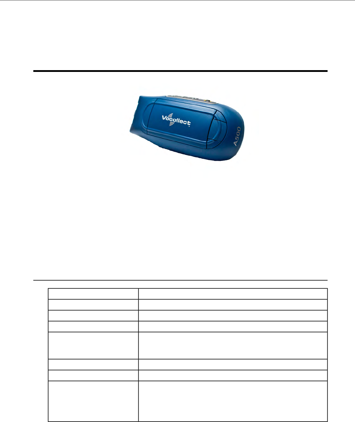
Chapter 3
Talkman A500
Figure 1: Talkman®A500
The Talkman®A500 couples a rugged design to function in harsh warehouse environments with wireless
capabilities. The device supports Bluetooth technology to connect to display devices as well as other
peripherals and headsets. In the Vocollect Talkman product line, the Talkman A500 offers expanded
operations with a more powerful processor, more available memory, and a more robust radio.
The A500 uses the same batteries, chargers, and headsets as the T5-Series devices. Both models use the
Vocollect VoiceClient voice software, but the A500 is designed to take advantage of Vocollect
VoiceCatalyst®functionality for best performance and enhanced features.
A500 Specifications
12.1 ounces (343 g) (with battery)Weight
5.5" (13.97 cm)Length
2.63" (6.68 cm)Width
1.7" (4.3 cm)Depth
I/O Ports • Headset port (yellow)
• Maintenance port with audio out and RS-232 serial support
-22° to 122° F (-30° to 50° C)Operating Temperature
-30° to 140° F (-34° to 60° C)Storage Temperature
Meets the MIL STD -810F specification for shock and vibration.
In addition, the device has been tested to the following specifications:
Drop Tested
• 25 drops from 5 feet, 10 additional drops from 6 feet onto polished
concrete
Confidential: For informational use by Vocollect Resellers and customers only

• 10 drops at varying angles from 5 feet at -20° F (-29° C) onto
polished concrete
100% condensingHumidity
IP67Enclosure Rating
Charging an A500 or T5 Device
Figure 2: Talkman A500/T5 High-Performance Battery
The A500/T5 battery is a high-performance model. Unlike the T2 series batteries, which have contact
points that are flush with the case, the A500/T5 battery features a pin-out design.
Caution: A500/T5 series batteries and other Vocollect batteries are not interchangeable. If you try
to insert the wrong battery into a device, you may damage the device and the battery.
The A500 and T5 devices use a Vocollect Combination Charger that charges the high-performance battery
while still seated in a device or when removed from the device.
A500/T5 High-Performance Batteries Specifications
Electrical Specifications
• Cells: The high capacity battery pack uses two lithium ion cells.
• Voltage = 3.7V
• Watt Hours = 19WHr
• Protection circuit characteristics: The pack contains a protection circuit that prevents over and under
voltage conditions on the cells and protects the pack from damage as a result of a short circuit between
the positive and negative terminals of the battery.
• The battery pack contains custom electronics that provide performance, temperature, and pack
identification to the device. This information is made available to voice management software.
• Battery Charging: The battery pack must be charged only in a Vocollect designated charger.
Confidential: For informational use by Vocollect Resellers and customers only
36 | Vocollect Hardware Documentation
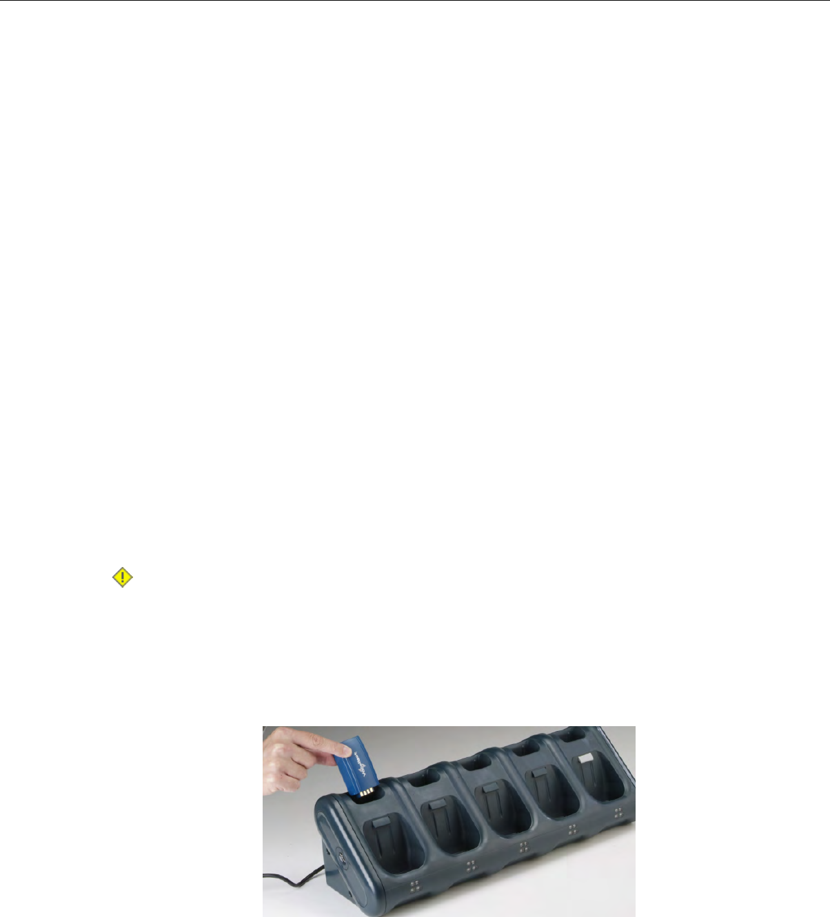
Mechanical and Environmental Specifications
• Drop-test specifications: The high capacity battery meets the MIL STD 810F specification for shock
and transient drop criteria.
• Environmental specifications: The battery pack halves are sonically welded together to protect the
internals from water and dust. The battery functions properly in the following conditions:
Temperature: -40°C to 55°C (-40°F to 131°F)
Humidity: 95% non-condensing
Rain/dust: IP67
Battery Notifications
Battery warnings for a Talkman battery occur at the following levels:
• First warning = 3,45 mV
• Critical warning = 3,350 mV
Charging an A500 or T5 Battery in a Device
1. Remove the device from the belt clip.
2. Disconnect any other peripherals.
3. Insert the device into an open slot on the charger, pressing down and then back until the device clicks
into place.
4. After the device has been placed into the charger, make sure that the LED indicator on the device
turns on and begins to blink green.
a) If the LED does not turn on after 30 seconds, remove the device from the charger slot and then
place it into the slot again.
b) If the LED indicator still does not turn on, try another charger slot.
Caution: Do not attempt to place the device into the charger unless you have first disconnected
the headset and any other peripheral devices. Do not remove the battery from the device when
placing a device into a charger.
Charging an A500 or T5-Series Battery
1. Remove the battery from the Talkman device.
2. Hold the battery with its contacts to the bottom and the Vocollect label facing you.
Figure 3: Inserting a Battery Into the Charger
3. Place the battery into an open battery slot on the top level of the charger.
Confidential: For informational use by Vocollect Resellers and customers only
Talkman A500 | 37
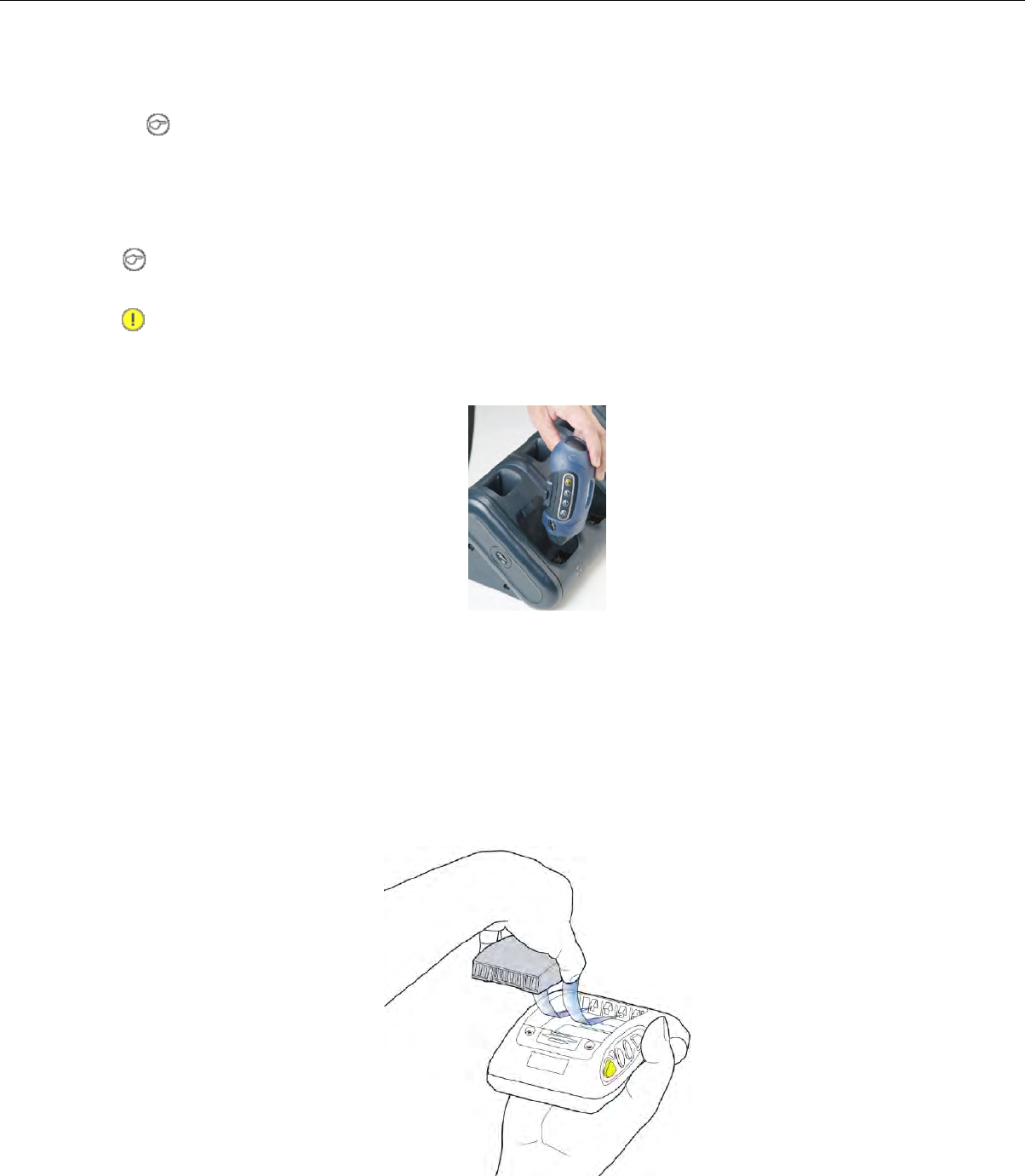
When the battery is placed into the charger properly, the left LED indicator for the slot into which
the battery was placed turns red.
Note: The upper set of LED indicators apply to the charger's battery slots and the lower indicators
apply to the devices' slots.
Removing an A500, T2-Series or T5-Series Device From a Charger
Note: The device is ready to use when the LED indicator on the device is blinking green. If the LED
is blinking red, the device is not ready to be used.
Important: If a device continuously displays a solid red light, contact your system administrator.
1. Make sure that the device is ready to use.
2. Pull up on the device to remove it from the device charger.
Figure 4: Removing a Device from a Charger
Inserting a Battery into a Talkman A500, T5-Series or T2-Series Device
Make sure the battery to be inserted is fully charged.
1. Hold the Talkman so that the red and yellow ports are facing away from you.
2. Hold the battery with the pins facing away from you and so that the Vocollect logo is on top.
3. Place the battery in at an angle, pins end first.
Figure 5: Properly Inserting a Battery
Confidential: For informational use by Vocollect Resellers and customers only
38 | Vocollect Hardware Documentation
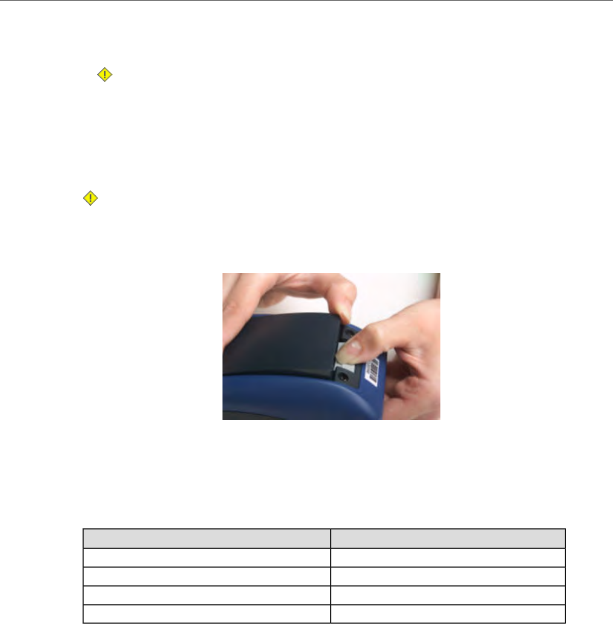
4. Push the back of the battery into place.
You will hear a click when the battery is in place.
Caution: Do not force the battery into the compartment. You may damage the battery or the
device. If the battery does not snap easily into place, reposition the battery in the compartment
and try again.
Make sure the battery is firmly in place and can't be removed without pressing the battery release button.
Removing a Battery from a Talkman A500, T5-Series or T2-Series Device
Make sure the Talkman device is off.
Caution: Do not remove the battery until the LED indicator is off. If you remove the battery when
the device is on or sleeping, any data collected could be lost.
1. Hold the device in one hand with the battery compartment facing toward you.
2. Press the battery release button all the way down until the top of the battery pops up from the battery
compartment.
Figure 6: Removing the Battery From a Device
3. Lift the battery out of the compartment.
Battery Warm-Up Time
If a battery has been used in a cold environment, it will not begin charging until it warms up sufficiently.
Approximate warm-up timeTemperature of battery use
6 minutes-4°C (24.8°F)
10 minutes-10°C (14.0°F)
22 minutes-20°C (-4°F)
30 minutes-30°C (-22°F)
Confidential: For informational use by Vocollect Resellers and customers only
Talkman A500 | 39

About LED Indicators
Vocollect Talkman devices, SRX and SRX2 headsets, and their chargers have LEDs that indicate the
state of the equipment. These LEDs may be on, off or blink. In some cases an LED will blink, alternating
between two colors.
If the LEDs indicate that there is a problem, refer to information on troubleshooting to solve the problem.
See also Troubleshooting Problems Indicated by LED.
A500 Device LED Indicators
A500StateLED
Device is onOn
Green
The device is in a chargerFast Blink
One of the following:Slow Blink
• the device is in sleep mode and not in a charger
• the voice application selection menu is in use
• certain portions of software are loading
Device is turning on
Device is turning off
On Briefly
Red
Error, contact system administratorOn Continuously
One of the following:Blinking
• retrieving and loading an operator from VoiceConsole
•retrieving, reading and loading a voice application from
VoiceConsole
• certain portions of software are loading
Wi-Fi offOff
Amber/Yellow
Wi-Fi on but not connectedFast Blink
Wi-Fi is on and connecting to a wireless networkSlow Blink
Bluetooth offOff
Blue
(Bluetooth
indicator)
Discovering/PagingFast Blink
ConnectedSlow Blink
Device is discoverableSeries of Blinks
Confidential: For informational use by Vocollect Resellers and customers only
40 | Vocollect Hardware Documentation

Pairing an A500 or T5 Device and a Bluetooth Device
You can associate one Bluetooth®printer and/or one Bluetooth bar code reader to the same A500 or
T5-series device. You cannot associate multiple printers or bar code readers to a single Talkman device.
Note: You can also associate a Pidion®BM-170 display with an A500 device.
Pairing with the Honeywell MS9535: Talkman Device Is the Initiator
1. In VoiceConsole, follow the instructions for creating a pairing and setting the bar code scanner as
the acceptor. See VoiceConsole's Help for details.
2. Scan the Code 128 bar code (3000CA7000000). See the documentation that came with the Honeywell
9535 for details.
3. Place the Talkman device and bar code reader close together. The Talkman device associates with
the bar code reader. A low-tone/high-tone beep from the bar code reader indicates a successful
association.
Note: If a bar code reader goes out of communication range with the Talkman device, it may un-pair
from the Talkman device. You will hear a high-tone/low-tone beep. Move the bar code reader closer
to the Talkman to reassociate the bar code reader with the Talkman device. You will hear a
low-tone/high-tone beep when they pair.
Pairing with the Honeywell MS9535: Talkman Device Is the Acceptor
The Talkman A500 and T5 devices must be configured in VoiceConsole to listen for incoming connections
before proceeding with these instructions. See the VoiceConsole online help for details.
For a T5 device, you must set the parameter Bluetooth_IsDiscoverable=true in the device properties in
VoiceConsole so that the device will broadcast its address.
Important: Only one scanner should be configured to communicate with a Talkman device's
Bluetooth address at any one time. If you change the bar code reader to which the device has been
paired, you must clear the Bluetooth service in the old bar code reader. Scan the Provide Bluetooth
Service bar code (3000CA7000000). See the documentation that came with the Honeywell scanner
for details.
1. With the Honeywell scanner, scan the Provide Bluetooth Service bar code (3000CA7000000). See the
documentation that came with the Honeywell scanner for details.
2. Power off the Talkman device completely and then power it back on.
3. Place the Talkman device into sleep mode or wait for it to enter sleep mode.
The green LED on the device blinks green.
4. Wait for 30 seconds.
5. Scan the Get Bluetooth Address bar code (3000CA7FFFFFF) from the Honeywell user's guide.
6. Scan the bar code on the Talkman device. This bar code contains the Talkman device's Bluetooth
address.
You will hear a quick, three-beep confirmation from the bar code reader, followed by a
low-tone/high-tone beep indicating success.
Pairing with Zebra QL Series Printers
For Bluetooth pairing:
Confidential: For informational use by Vocollect Resellers and customers only
Talkman A500 | 41

• In VoiceConsole, find the device and use the appropriate action link to pair it to a peripheral.
• See VoiceConsole Help for detailed instructions on pairing devices.
• Create the pairing with the Zebra®QL™Series printer.
Pairing with Intermec PB50 Printers
Please refer to Intermec documentation on configuring the PB50 for Vocollect applications.
For Bluetooth pairing:
• In VoiceConsole, find the device and use the appropriate action link to pair it to a peripheral.
• See VoiceConsole Help for detailed instructions on pairing devices.
• Create the pairing with the Intermec®PB50 mobile printer.
For Wireless Network (WiFi) pairing:
• In VoiceConsole, find the device and use the appropriate action link to pair it to a peripheral.
• Enter the printer's Pairing Name, Host, and Port.
The default TCP/IP port for the PB50 printer is 9100.
• See VoiceConsole Help for detailed instructions on pairing devices.
Pairing the Honeywell LXE 8652 Scanner: Talkman Device Is the Initiator
During use, it is possible for the scanner to disconnect from the device if the communication link is
disrupted. When the scanner is setup so that the device initiates the connection, the device typically
recovers the connection automatically. When the scanner initiates the connection, it typically requires
the press of a button to activate and recover the connection..
This method of pairing is useful if a single Talkman T5 Series device will always be associated with one
scanner.
You must have access to VoiceConsole to set up the pairing. For production use, Vocollect recommends
that you create a specific device profile in VoiceConsole to store many of the following settings.
1. Print this page.
2. Scan the following barcode to ensure that the Honeywell LXE®8652 scanner is ready to accept a
connection, even if it was previously paired.
Caution: The scanner may not accept a connection if this barcode is not scanned.
Figure 7: Set Up Scanner as Slave
3. Using VoiceConsole, locate the specific Talkman T5 device to be paired with the scanner.
4. View the properties of the device, and ensure that Bluetooth is enabled. If it is not enabled, click Edit
this device and set Bluetooth Enabled to "enabled."
5. Select the Pair this device with a peripheral option.
6. For Pairing Type select "Bluetooth Scanner."
7. For Connection Mode select "Device initaties connection with peripheral."
Confidential: For informational use by Vocollect Resellers and customers only
42 | Vocollect Hardware Documentation

8. In the Bluetooth Adress enter the Bluetooth MAC address of the scanner. This 12-character ID is
labeled "MAC ID" and is found on the side of the battery unit of the scanner.
9. Click Pair with peripheral to initiate pairing.
Pairing the Honeywell LXE 8652 Scanner: Scanner Is the Initiator
During use, it is possible for the scanner to disconnect from the device if the communication link is
disrupted. When the scanner is setup so that the device initiates the connection, the device typically
recovers the connection automatically. When the scanner initiates the connection, it typically requires
the press of a button to activate and recover the connection..
This method of pairing is useful if a scanner will be used with more than one Talkman T5 Series device.
You must have access to VoiceConsole to set up the pairing. For production use, Vocollect recommends
that you create a specific device profile in VoiceConsole to store many of the following settings.
1. Ensure that the Talkman is labeled with a code 128 barcode. This code contains the FNC3 code
followed by the capital letter "B" and the unique Bluetooth MAC address of the Talkman.
a) If the Talkman does not have a barcode label, generate the FNC3 on a PC with a full keyboard
and number pad. Hold the ALT key down and press the four-number sequence "1 0 7 9" on the
number pad. A small number 3 will appear to indicate the presence of the code. Some barcode
software packages have special insertion keystrokes for FNC3.
b) Find the Bluetooth MAC address of the Talkman on the rear of the device near the belt clip. The
address begins with "BT."
2. Print this page.
3. Using VoiceConsole, locate the specific Talkman T5 device to be paired with the scanner.
4. View the properties of the device, and ensure that Bluetooth is enabled. If it is not enabled, click Edit
this device and set Bluetooth Enabled to "enabled."
5. Select the Pair this device with a peripheral option.
6. For Pairing Type select "Bluetooth Scanner."
7. For Connection Mode select "Device listens for peripheral connection."
8. Click Pair with peripheral to initiate pairing.
9. To complete the pairing, scan the barcode created for the Talkman device in first step.
10. When finished using the Talkman and scanner, unpair the Talkman by scanning the following barcode
to set the scanner to slave mode.
Note: Performing this step ensures that the scanner does not generate spurious Bluetooth RF
that could interfere with other transmissions.
Figure 8: Reset Scanner as Slave
Note: To pair the scanner again, rescan the Talkman code 128 barcode.
Confidential: For informational use by Vocollect Resellers and customers only
Talkman A500 | 43

Pairing the Socket Cordless Ring Scanner with a Talkman T5
During use, it is possible for the scanner to disconnect from the device if the communication link is
disrupted. When the scanner is setup so that the device initiates the connection, the device typically
recovers the connection automatically. When the scanner initiates the connection, it typically requires
the press of a button to activate and recover the connection..
The Bluetooth connection between the Socket®Cordless Ring Scanner (CRS) and a Talkman T5 is
managed through VoiceConsole. See VoiceConsole Help for details on the use of Bluetooth with Vocollect
Voice systems.
Note that Each CRS has a unique Bluetooth address that is clearly labeled on the underside of the
wrist-worn Bluetooth transmitter and battery pack. This address is needed to associate a CRS with a
T5.
Because a T5 will be explicitly associated with a specific CRS via VoiceConsole, Vocollect strongly
recommends clearly labeling the CRS wrist units to identify them with the specific T5 to which they are
paired. A clear identification and operational procedure for keeping specific scanners associated with
specific Talkman T-Series devices will be beneficial in the work environment.
Connecting the CRS to the Talkman T5 Device
The Socket Cordless Ring Scanner, with scanner part number ending in REV D, can be paired with a
T5-series device where the scanner acts as the initiator.
You must have access to VoiceConsole to set up the pairing. For production use, Vocollect recommends
that you create a specific device profile in VoiceConsole to store many of the following settings.
1. In VoiceConsole, select Bluetooth scanner as the pairing type for the device you want to pair with
the scanner. For the Connection Mode, select Device listens for peripheral connection. See VoiceConsole
Help for details.
2. Create a bar code using Symbology Code 128 in the following form, where AABBCCDDEEFF is the
Bluetooth MAC address found on the T5: #FNIAABBCCDDEEFF#
a) Bar codes can be created at a Web site such as www.barcoding.com/upc.
3. Turn on the Socket CRS and the T5.
4. Scan the bar code you created.
The scanner beeps and begins flashing rapidly. It is now searching for the device.
5. Place the scanner and device closely together to pair.
The Bluetooth LED on the scanner blinks once every four seconds to indicate that the scanner and
device have paired.
Installing an A500 or T5-Series Device Into a Vehicle
A Talkman A500/T5 VMT Mobile Computer, is an A500 or T5-Series device with a battery adapter
mounted to a vehicle, such as a forklift or motorized pallet jack. After the device is mounted, the battery
adapter is placed in the battery area of the A500 or T5-Series device (connected to the vehicle’s power
source).
Talkman devices in this configuration may use any wired or wireless equipment (headsets, scanners,
etc.). Vocollect sells the complete solution including mounting kits and power systems to enable any
Talkman A500 or T5-Series devices to be used in an A500/T5 VMT configuration.
Caution: PLEASE DO NOT LOOK AT DEVICE/UNIT WHILE OPERATING MACHINERY SO
AS TO AVOID CREATION OF A DISTRACTION THAT COULD RESULT IN AN ACCIDENT AND
BODILY INJURY TO OPERATOR AND THIRD PERSONS.
Confidential: For informational use by Vocollect Resellers and customers only
44 | Vocollect Hardware Documentation
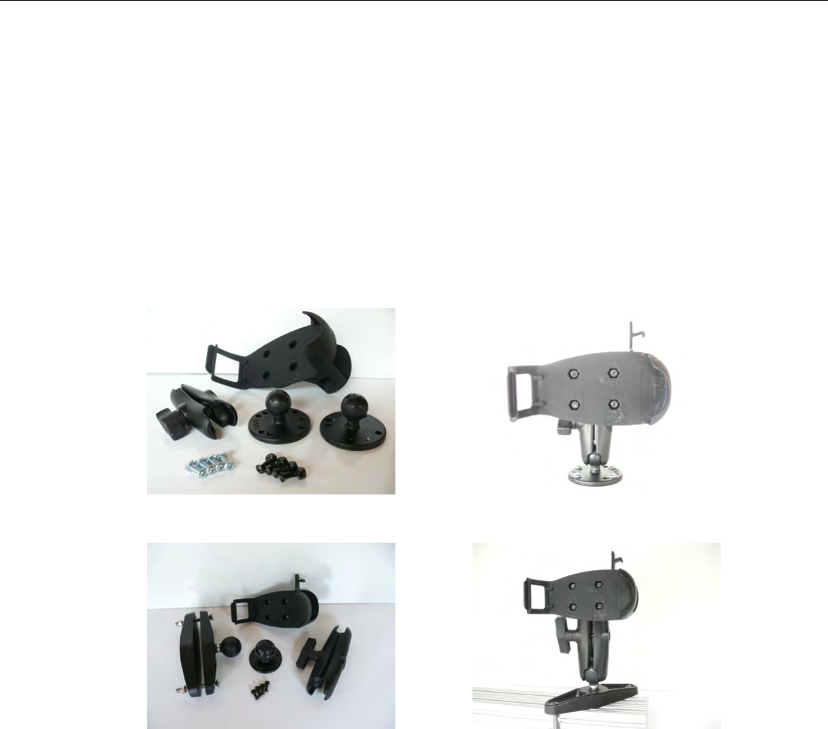
Follow the instructions below to properly install the device in a forklift.
• Determine the best location for mounting the device, taking into consideration the driver’s field of
view.
• Install the appropriate mounting hardware.
• Connect the device to the vehicle’s wiring system.
Talkman A500/T5 VMT Mobile Computer Accessories
The Talkman A500/T5 VMT Mobile Computer is designed to be installed using RAM Mounting Systems
hardware. Vocollect supplies a mounting bracket for the A500/T5 and mounting hardware from RAM
Mounting Systems. Additional hardware mounting bracket options can be purchased directly from RAM
Mounting Systems (www.ram-mount.com) to customize the installation.
The A500/T5 VMT must be mounted to a sturdy surface.
Figure 10: Screw On MountingFigure 9: Screw On Mounting Parts
Figure 12: Clamp MountingFigure 11: Clamp Mounting Parts
Confidential: For informational use by Vocollect Resellers and customers only
Talkman A500 | 45
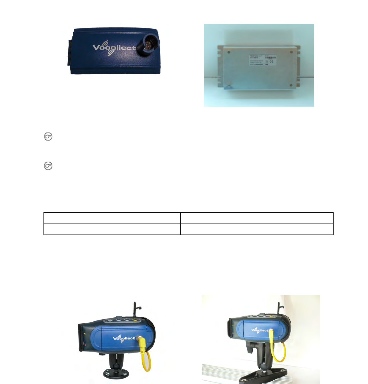
Figure 14: Power Supply
Figure 13: Battery Adapter
Note: You may provide your own power supply, but it must supply 12-15V at 1 Amp and must be
limited to less than 250VA (Watts). If you chose to provide your own, you are still required to purchase
the battery adapter cable and battery adapter for final connection to the A500 or T5-Series device.
Note: This configuration does not require you to connect the A500 or T5-Series device to the vehicle's
power source. If desired, for operational reasons, T5-Series devices may be used in VMT configuration
using a Vocollect battery.
Talkman A500/T5 VMT Mobile Computer Accessory Specifications
-30° to 50° C (-22° to 122° F)Operating Temperature
-40° to 70° C (-40° to 158° F)Storage Temperature
Mounts for Talkman A500/T5 VMT Mobile Computers
The Screw On Mount is a mounting option that is bolted to a stationary surface on a vehicle.
The Clamp Mount is a mounting option that is clamped to a stationary surface on a vehicle. This can
also be bolted to a stationary surface, if desired.
Figure 16: Clamp MountFigure 15: Screw On Mount
Confidential: For informational use by Vocollect Resellers and customers only
46 | Vocollect Hardware Documentation

Positioning the Talkman A500/T5 VMT Mobile Computer
• Determine the best position for the device and all the associated components. If a similar device was
previously installed, check to see if the position it used is suitable for the device.
• Test the installation for at least 30 minutes before installing on another vehicle. Record all details:
• Check that the position of the device does not obstruct vehicle controls.
• Check that the device does not obstruct the driver's view.
• Check the position of the device for user comfort over long periods.
Installing the Mounting Brackets for a Talkman A500/T5 VMT Mobile Device
The following parts are supplied by Vocollect for attaching the screw on mount:
DescriptionQuantityItem #
Vehicle Mount, Holder/Base Screw On Attachment21
Vehicle Mount, Arm12
Vehicle Mount, Holder13
The following parts are supplied by Vocollect for attaching the clamp on mount:
DescriptionQuantityItem #
Vehicle Mount, Clamp11
Vehicle Mount, Arm12
Vehicle Mount, Holder13
Vehicle Mount, Holder/Base Screw On Attachment14
1. Drill the holes required to secure the base to the vehicle. If using the clamp mount, skip this step.
2. Note: Apply some lubricant (for example, light oil or anti-sieze) to the threads of the clamp
mount screws.
Screw or clamp a base to the location.
3. Attach the other base to the other end of the arm and tighten once in the desired location by turning
the locking lever clockwise.
4. Screw the device holder to the base.
5. Insert a device into the holder, and insert the battery adapter into the device.
6. Attach the cable from the power supply to the battery adapter.
To prevent vibration, the arm of the mounting bracket should not touch the stem of the ball of the base.
In other words, the arm should not be tilted so far as to have these pieces touching.
Confidential: For informational use by Vocollect Resellers and customers only
Talkman A500 | 47
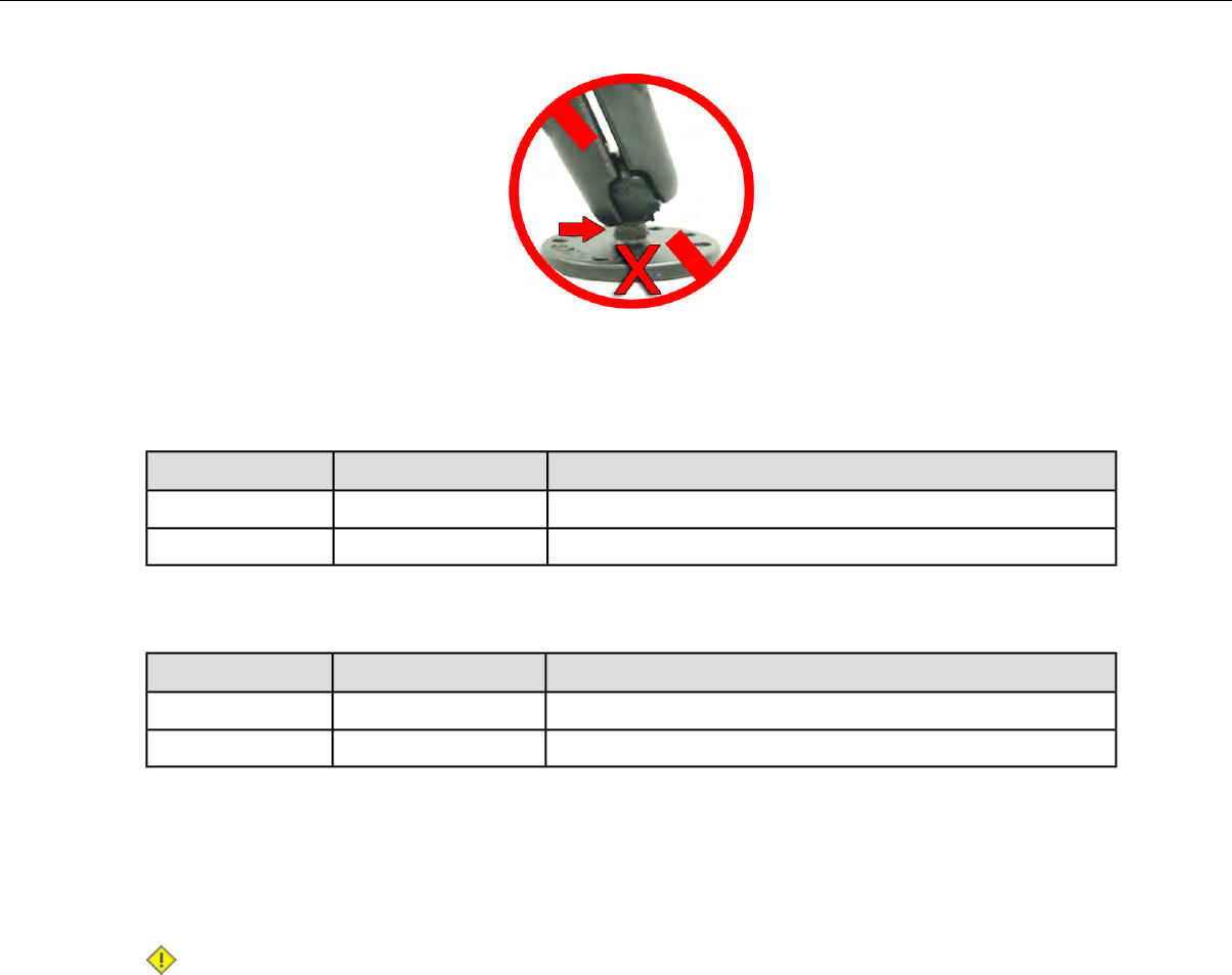
Connecting Cables to the Power Supply and Attaching the Power Supply to a Vehicle
The following parts are supplied by Vocollect for attaching the 12 or 24 volt vehicle's power supply to a
device:
DescriptionQuantityItem #
Power Supply, 9-36 VDC Input11
Cable from power supply to battery adapter12
The following parts are supplied by Vocollect for attaching the 36 or 48 volt vehicle's power supply to a
device:
DescriptionQuantityItem #
Power Supply, 18-60 VDC Input11
Cable from power supply to battery adapter12
You will need the following equipment:
• One Cable from the power supply to vehicle’s power source. Vocollect recommends an industrial rated
cable with the following specifications: Number of conductors = 3, Gauge of wire = 16, Temperature
= -40C to 90C
• Cable ties
Caution: General Guidelines for Routing Electrical Cables
• The vehicle must be off and the vehicle's battery must be disconnected.
• Cables should be kept clear of surfaces that may become hot.
• Cables should not be run such that they can get caught on moving parts.
• Cables should not be run on the outside of a vehicle.
• Cables should not have 90 degree turns, the minimum bend radius should not be less than one
inch
• To remove slack on a cable it should be coiled up and secured inside the vehicle with a cable tie.
• For maximum safety fuses should be located as close as possible to the power source.
• To protect the A500/T5 VMT from power surges and to perform voltage conversion a converter
module is fitted between the A500/T5 VMT and the forklift battery.
1. Disconnect the vehicle battery.
2. Remove the four screws from the top of the power supply to expose the screw terminals.
3. On the cable from power supply to the vehicle’s power source, strip the three cables to expose
approximately 5mm of copper. Ensure the cable is long enough to reach from the power supply to the
vehicle’s power source.
Confidential: For informational use by Vocollect Resellers and customers only
48 | Vocollect Hardware Documentation
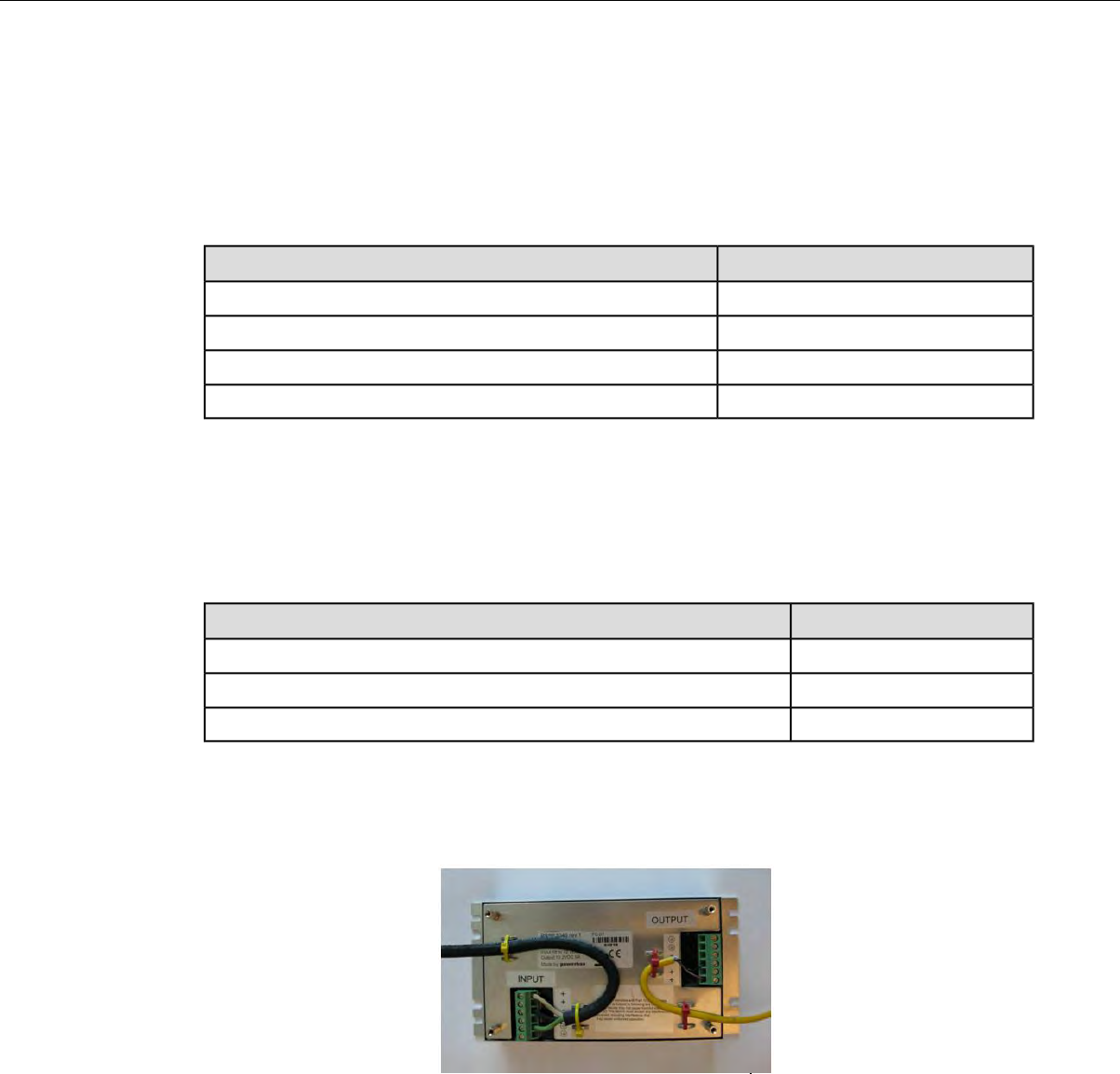
4. On the yellow cable from the battery adapter to the power supply, strip the black and brown cable to
expose approximately 5mm of copper. The Blue cable is not required; it can be trimmed where it exits
the yellow cable. Ensure the cable is long enough to reach from the power supply to the vehicle’s
power source.
5. Connect the cables from the battery adapter to the power supply by performing the steps below.
• Loosen the screws to where the connection will be made on the power supply.
• Match the cables to the correct locations as indicated in the chart below:
•Output ConnectorCable
+Brown – Battery Adapter Positive
-Black – Battery Adapter Negative
GNDNo connection needed
Not applicableBlue (cut back)
• Tighten the screws.
• Ensure the cables are secure
6. Connect the cables from the vehicle’s power source to the power supply by performing the steps below:
• Loosen the screws to where the connection will be made on the power supply.
• Match the cables to the correct locations as indicated in the chart below:
•Input ConnectorCable
+White (may differ depending on the cable) – Vehicle Positive
-Black (may differ depending on the cable) – Vehicle Negative
GNDGreen - Vehicle Ground
• Tighten the screws.
• Ensure the cables are secure
7. Once all of the cables have been successfully installed, attach cable ties to secure the cables.
Figure 17: Cables Attached to the Power Supply
8. Place the power supply in a place out of the way, such as under the dashboard of a fork lift, and attach
it to a secure surface with cable ties. Alternatively the power supply could be secured by bolting it
using the mounting slots.
Confidential: For informational use by Vocollect Resellers and customers only
Talkman A500 | 49

Figure 18: Power Supply Attached to a Secure Surface on the Vehicle
9. Run the cable that connects the battery adapter to the power supply from the power supply to the
location where the A500/T5 VMT will be mounted
10. Connect the yellow wire to the battery adapter by attaching the connector and tightening the nut.
Connecting the Talkman A500/T5 VMT Mobile Computer to a Vehicle's Power Source
You will need the following equipment:
• Two fuse holders from Cooper Bussman. Vocollect recommends using a Cooper Bussmann HFA series
in line waterproof fuse.
• Two fuses. Vocollect recommends a 2A 250V SLO BLO fuse.
• Three spade connectors
• Four small cable ties
• Fasteners
Vocollect recommends choosing unswitched power as the source for the power supply. This will allow
Talkman devices to be powered for software updates as well as prevent Talkman devices from accidentally
being unpowered if the vehicle is quickly switched off unintentionally.
1. Remove all power sources from the vehicle.
2. Remove any excess length from the cable from the input cable from the power supply.
3. Connect the fuses to the cable near to the battery end of the cable. Remove approximately 4 inches
of the outer insulation from the cable.
4. Expose approximately 10mm of copper on the positive and negative wires.
5. Insert the exposed copper into the fuseholders and crimp into the positive and negative wires using
an approved tool.
6. Connect the green wire to the vehicle's ground.
7. Connect the fused white wire to the vehicle’s positive power source using an appropriate connector.
This may need to be crimped onto the wire.
8. Connect the fused black wire to the vehicle’s negative power source using an appropriate connector.
This may need to be crimped onto the wire.
9. Attach the power supply as shown in the following diagram.
Confidential: For informational use by Vocollect Resellers and customers only
50 | Vocollect Hardware Documentation
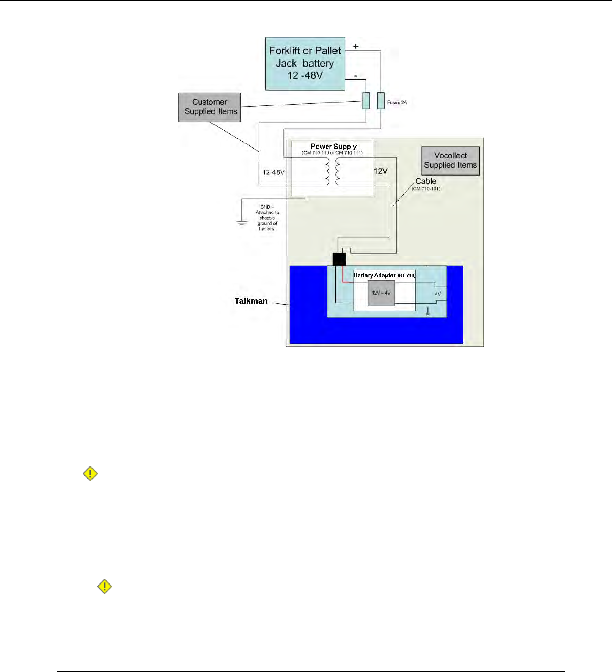
Figure 19: Attach the Power Supply
10. Secure the wires with cable ties.
Removal of Talkman A500/T5 VMT Mobile Computer from Vehicle
Talkman A500/T5 VMT mobile computer components are designed for easy removal for occasional vehicle
service, maintenance or flexible operational needs.
Caution: Vocollect does not recommend removing the cables (CM-710-101, CM-710-102) from the
battery adapter except when required for occasional service (i.e. once per month at maximum)
Excessive removal of these cables may damage the adapter and cable. This type of use is not covered
under warranty or service plans as it is unintended product use that is specifically not recommended.
1. Release the battery adapter from the device.
2. Dock the battery adapter in the side of the VMT holder.
This leaves the device free to be removed and the battery adapter and cable docked and protected.
Caution: The battery adapter should remain cabled and docked when not in use to prevent cable
damage or accidental contact of the adapter contacts with metal surfaces.
Accessories
Vocollect offers a variety of accessories for wearing, protecting, and facilitating the operations of Talkman
and other handheld devices.
Confidential: For informational use by Vocollect Resellers and customers only
Talkman A500 | 51
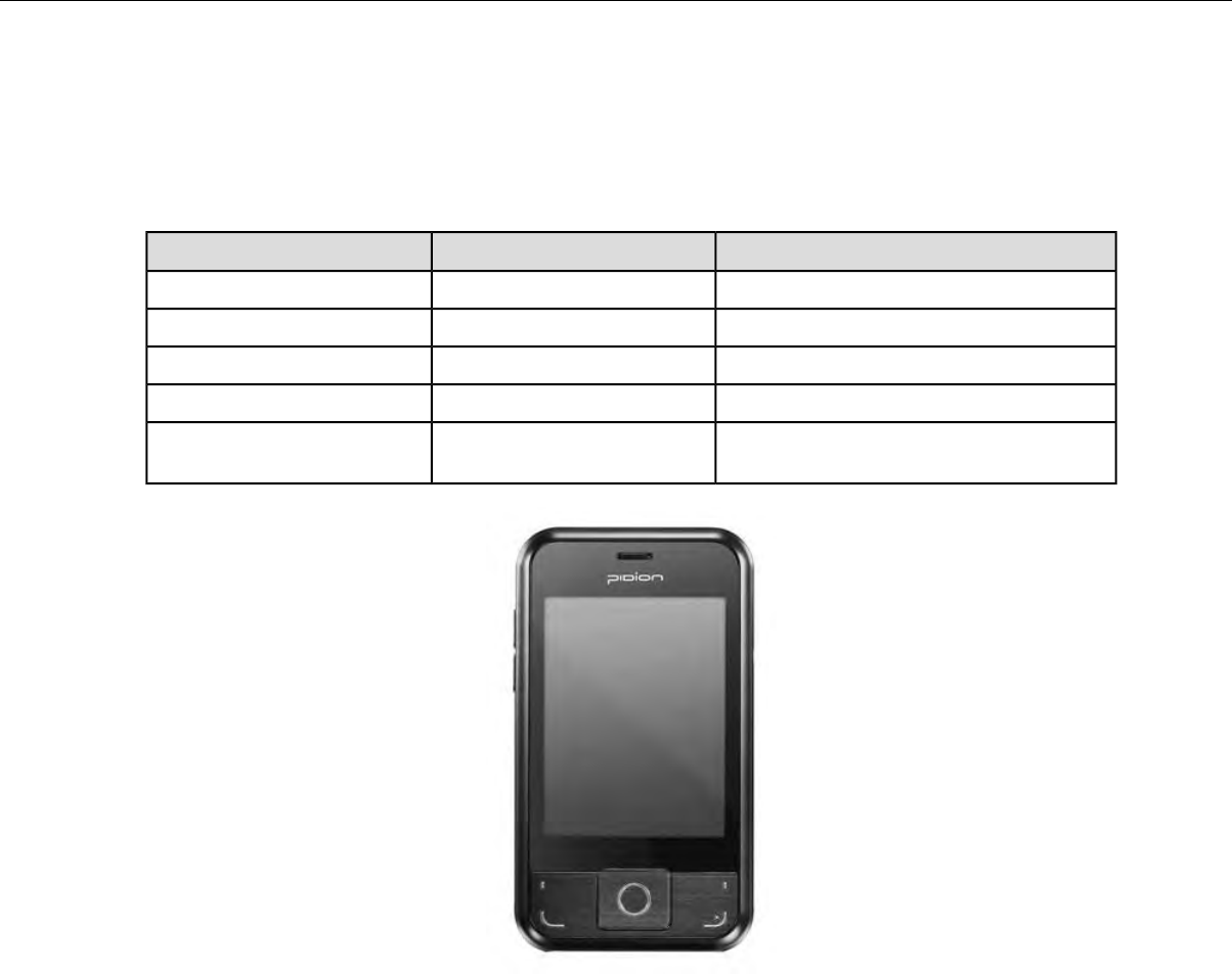
Pidion BM-170 Display
The Pidion BM-170 is a display device that can be used along with a Talkman A500 to run applications
where it is more appropriate that voice be supplemented with a display. It has a touchscreen and various
buttons and switches:
ActionLocationControl
Increases and decreases volumeLeft sideRocker switch
Powers on and offRight sideLarge button
BackRight sideSmall button
Displays options availableUpper left of frontOptions menu
Navigates around screen and lets you
select items
Center frontJoypad
Figure 20: Pidion Display Device
Connecting the Pidion BM-170 Display to a Talkman A500
1. Turn on the Talkman A500.
2. Turn on the display.
The display will initialize.
Confidential: For informational use by Vocollect Resellers and customers only
52 | Vocollect Hardware Documentation
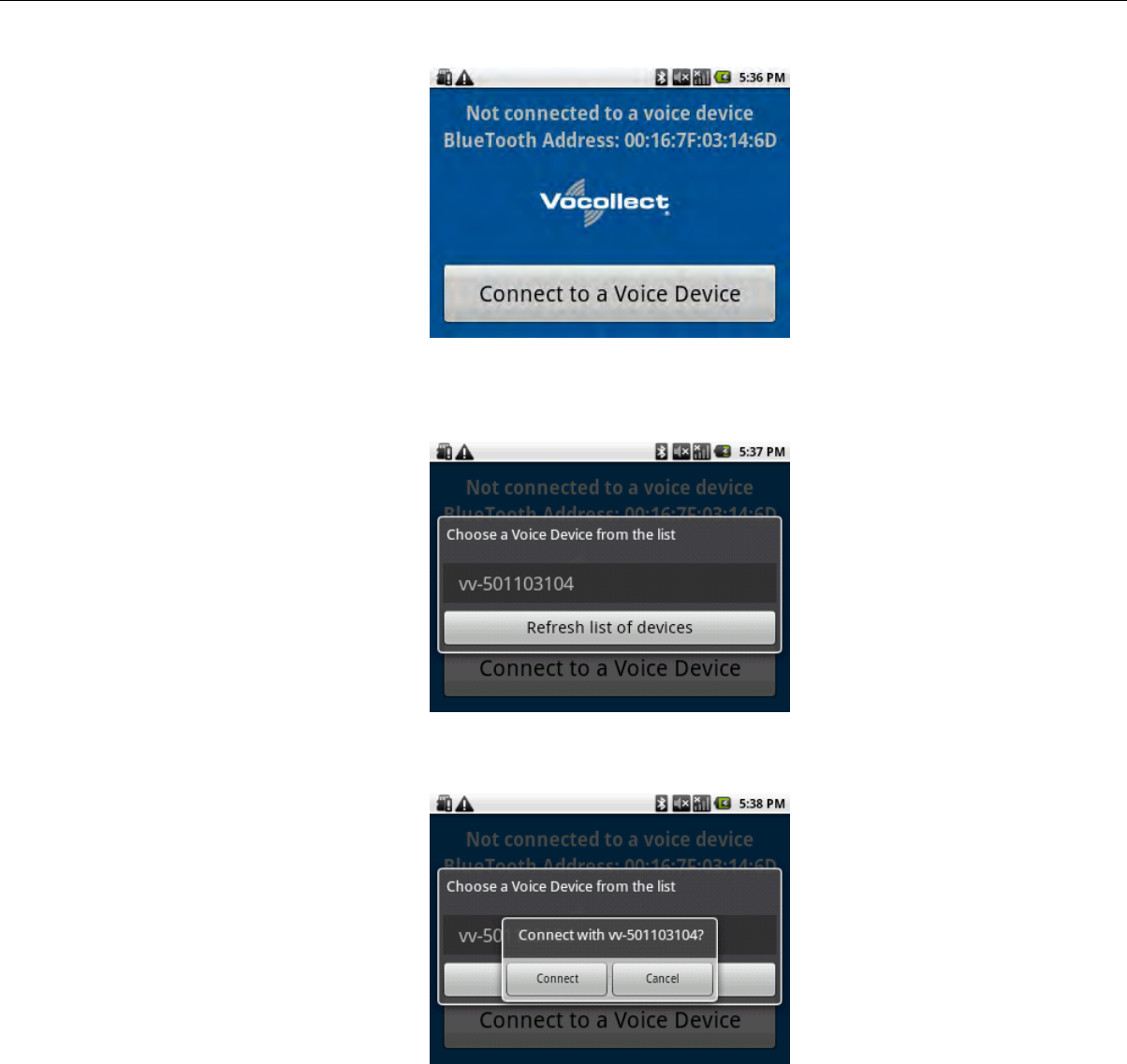
Figure 21: The Initial Screen
3. Press the Connect to a Voice Device button to begin connecting the display to your Talkman.
A list of nearby devices' serial numbers that can accept a connection are displayed.
Figure 22: List of Devices
4. Select the serial number of the Talkman to which you want to connect and confirm your selection.
Figure 23: Confirming the Connection
You will be taken back to the main screen, and the display will be connected to the Talkman.
Confidential: For informational use by Vocollect Resellers and customers only
Talkman A500 | 53
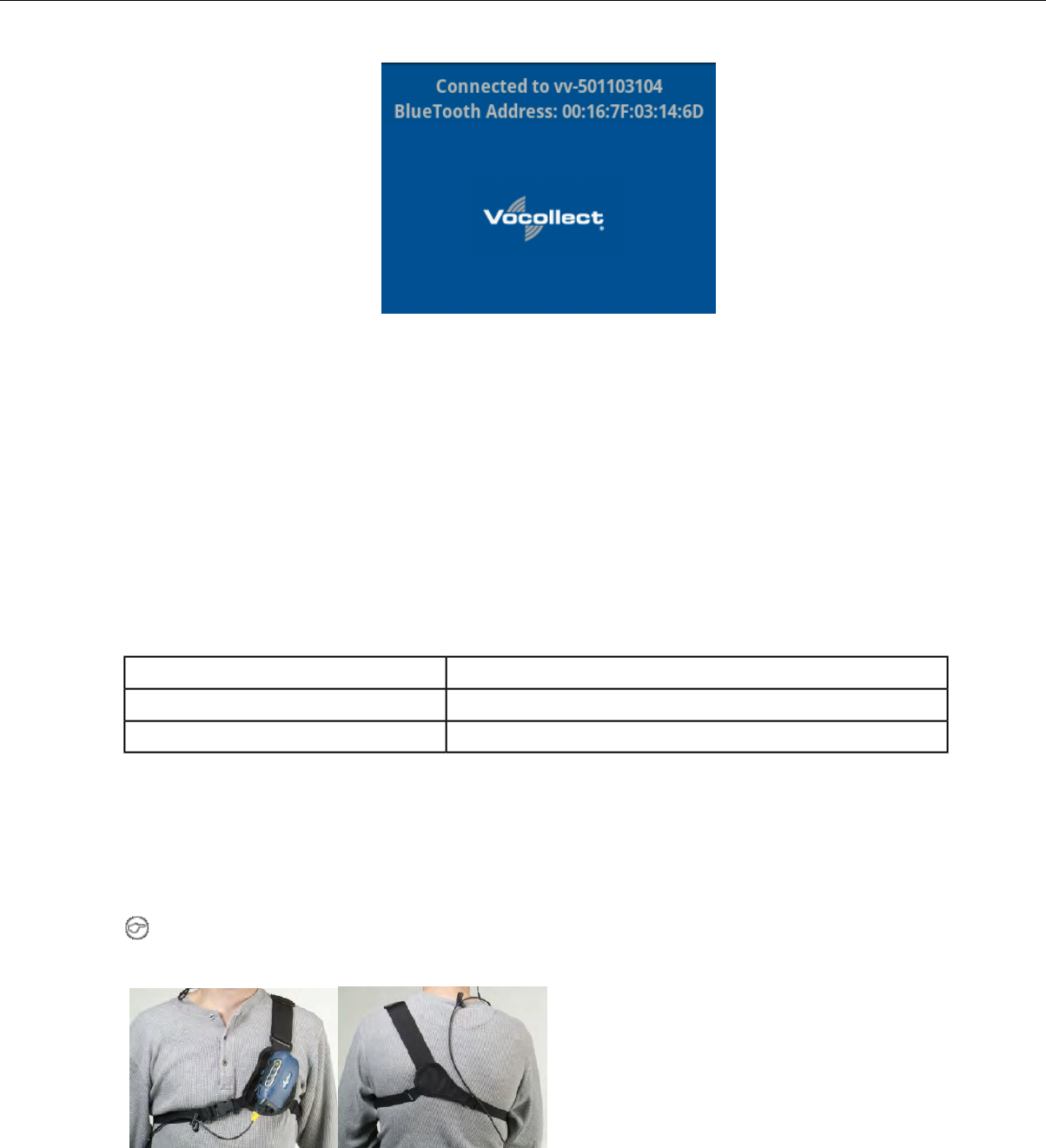
Figure 24: Connected to a Voice Device
Screens relevant to the application loaded onto the voice device will appear once the voice application
is running.
T5/A500 Adjustable Shoulder Harness
Operators wear devices on an adjustable shoulder harness that is purchased from Vocollect. The device
is attached to the shoulder harness with a specially designed clip.
Operators must regard the clip and the device as two separate entities. The clip should be attached to
the Vocollect shoulder harness at the beginning of a shift. Then, the operator can attach the device to
and remove the device from the clip as often as necessary throughout the shift.
T5/A500 Adjustable Shoulder Harness Specifications
2" (5 cm) Wide Adjustable NylonShoulder Strap
Two Adjustable Elastic Nylon, 32"-48"(81 cm - 122 cm)Chest Straps (Regular)
Two Adjustable Elastic Nylon, 41"-66" (104 cm - 167 cm)Chest Straps (Large)
Putting a Device on a T5/A500 Shoulder Harness
To mount a device onto the specially designed belt or shoulder harness, an operator must have a slim
belt clip (provided with the belt or harness). The clip should be attached to the belt at the beginning of
a shift. Then, the operator can attach the device to and remove the device from the clip as often as
necessary.
Note: Vocollect strongly recommends that the device be worn on the right side of the body with the
device's buttons on the top and its connectors toward your back.
Figure 25: T5/A500 Shoulder Harness Properly Worn - Front and Back Views
Confidential: For informational use by Vocollect Resellers and customers only
54 | Vocollect Hardware Documentation
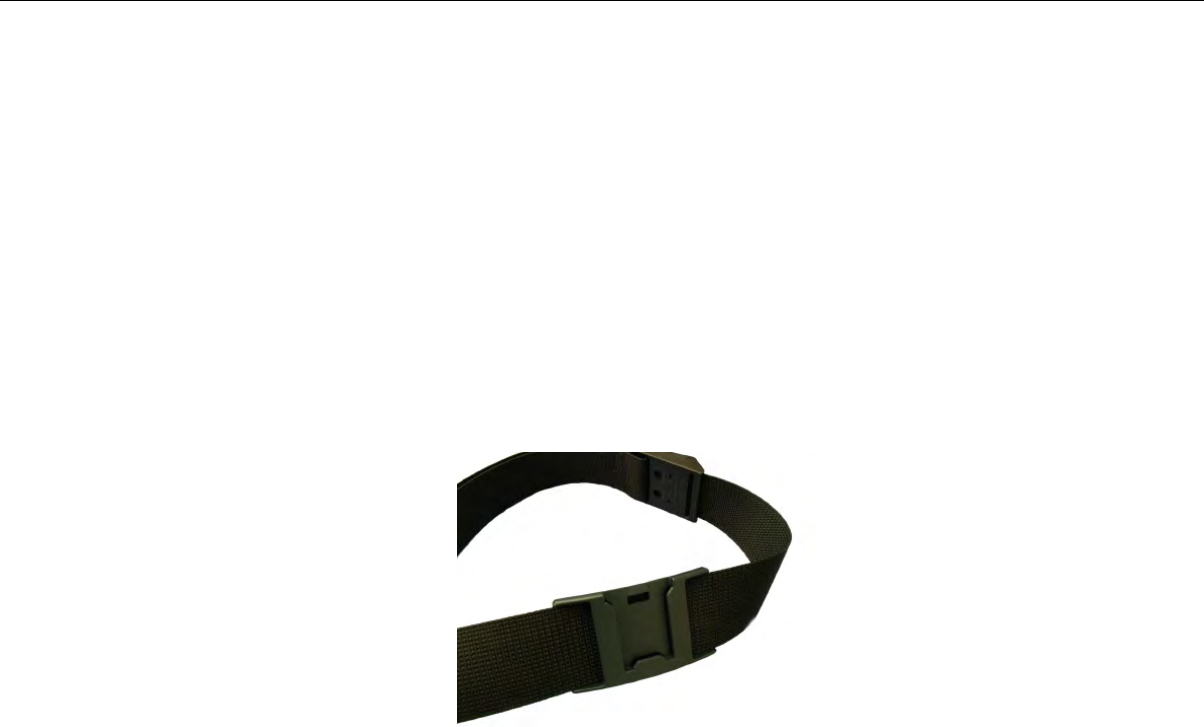
1. Open the flap on the front of the shoulder harness by unsnapping the two buttons.
2. Slide the flap through the slots on the belt clip.
3. With the clip all the way on the flap, snap the buttons together.
4. Unbuckle the large loop.
5. Put your left hand through the small loop and slide the harness over your left shoulder.
6. Clip the large loop in front of your chest.
7. Adjust the straps.
8. Connect the device to the shoulder harness clip by sliding the device onto the clip until it snaps into
place.
The device is properly clipped in place if you cannot remove it from the clip without pressing the device's
clip release button.
Belts and Belt Clips
Figure 26: Belt with Clip
Operators wear devices on a customized belt that is purchased from Vocollect. The device is attached to
the belt with a specially designed clip or holster.
The clip is attached to the Vocollect belt at the beginning of a shift. The operator can attach the device
to and remove the device from the clip as often as necessary throughout the shift. Vocollect sells three
types of mounting clips:
• T2 Series Slim Blue Belt Clip: connects a devi ceto the customized belt.
• T2 Series Heavy Duty Belt Clip: adapts an OPEN belt (sold with Vocollect's previous device) for use
with a T2 Series device.
• T5/A500 Black Belt Clip: connects a T5 or A500 device to the belt.
• To comply with government safety standards, the device must be used with either a Vocollect
customized belt and clip, a Vocollect customized shoulder harness, or a Vocollect belt holder.
• Vocollect strongly recommends that the device be worn on the right side of the body with the device’s
buttons on the top and its connectors toward your back.
Using the T-Series Belts and Clips
To mount a device onto the specially designed belt or shoulder harness, an operator must have a slim
belt clip (provided with the belt or harness). The clip should be attached to the belt at the beginning of
a shift. Then, the operator can attach the device to and remove the device from the clip as often as
necessary.
• A500 and T5-series devices can be worn on a belt or shoulder harness.
Confidential: For informational use by Vocollect Resellers and customers only
Talkman A500 | 55

Figure 27: Attaching the Device to a Belt Clip
T-Series Belt Specifications
DimensionsBelt Size
18" - 26" (46cm-66cm)XS
24" - 32" (61cm-81cm)S
28" - 36" (71cm-91cm)M
34" - 42" (61cm-107cm)L
40" - 48" (102cm-122cm)XL
46" - 54" (117cm-137cm)XXL
52" - 60" (132cm-152cm)XXXL
SpecificationBelt Part
NylonBelt material
YKK Hook and LoopVelcro®
ITW Nexus 127-3200Belt fastener
Device Covers
Vocollect offers an optional protective covers for its devices.
• The use of a device cover is not required; however, Vocollect strongly recommends using the cover to
help preserve the appearance and prolong the life of the devices.
• Using the protective cover in a freezer environment prolongs battery life.
Confidential: For informational use by Vocollect Resellers and customers only
56 | Vocollect Hardware Documentation
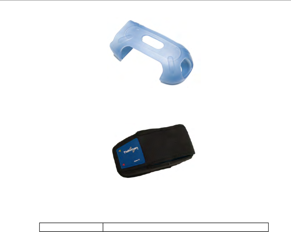
Figure 28: A500/T5 Elastomer-SKIN Cover
• The device cover does not have to be removed before placing the device into a device charger.
• The EXO Skeleton Cover provides additional drop protection for the device, is easy to remove, and
permits full access to all device features and functions.
Figure 29: T2-Series Device Cover
• You must remove the device cover before placing the device into a device charger. Failure to do so
could result in damage to both the device and the charger.
T5/A500 Elastomer-SKIN Cover Specifications
ThermoPlastic Elastomer (Dynaflex G2755)Fabric
Putting a Cover on an A500 or T5-Series Device
1. If the device is not already off, press and hold the yellow play/pause button until the LED indicator
turns solid red and then off.
2. Disconnect any peripherals.
3. Hold the device with the battery compartment facing up and the device's buttons facing toward you.
4. Slide the open end of the cover over the connection port end of the device. Pull gently on the cover to
make sure it slides behind the tab, located on the bottom of the device, that holds the cover securely
in place.
Confidential: For informational use by Vocollect Resellers and customers only
Talkman A500 | 57

Figure 30: Putting a Cover on a Talkman T5-Series Device
5. Stretch the rounded end of the cover over the rounded end of the device.
6. Attach the peripherals that you will be using.
Confidential: For informational use by Vocollect Resellers and customers only
58 | Vocollect Hardware Documentation
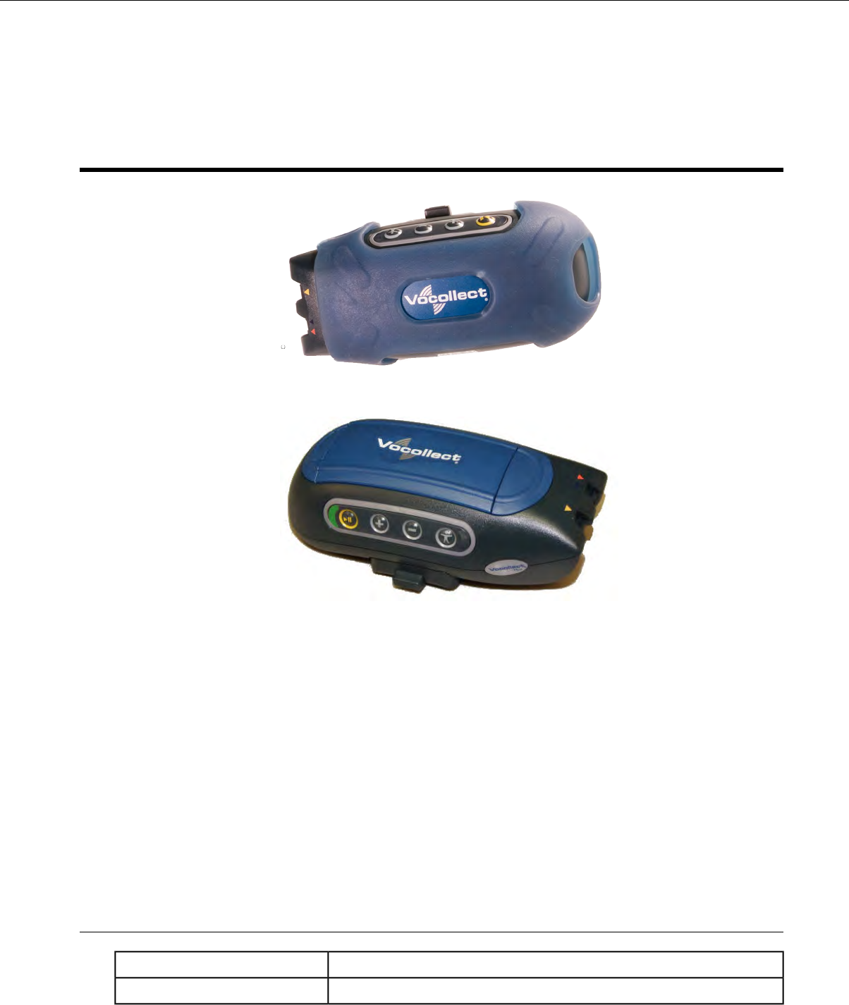
Chapter 4
Talkman T5 Series
Figure 31: Talkman T5
Figure 32: Talkman T5m
The Talkman®T5 is a compact, lightweight, voice-enabled device with wireless capability that is designed
to perform in the harsh conditions of an industrial environment. The Talkman T5mis the enhanced
memory version with increased memory and data storage.
Talkman T5-Series Features
• Bluetooth®compatible radio enables wireless connections to headsets, bar code readers, printers, and
other peripherals
• High-performance battery ensures uninterrupted power even in freezing conditions
• Ergonomic design provides user comfort with belt or shoulder harness
• Elastomer device cover protects your investment
• Four-button interface enables easy user interaction
T5-Series Specifications: Talkman T5 and Talkman T5m
12.1 ounces (343 g) (with battery)Weight
5.5" (13.97 cm)Length
Confidential: For informational use by Vocollect Resellers and customers only
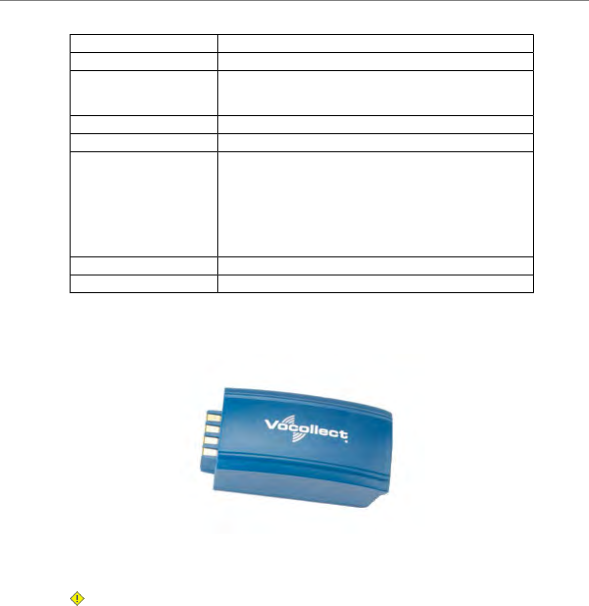
2.63" (6.68 cm)Width
1.7" (4.3 cm)Depth
I/O Ports • Headset port (yellow)
• Maintenance port with audio out and RS-232 serial support
-22° to 122° F (-30° to 50° C)Operating Temperature
-30° to 140° F (-34° to 60° C)Storage Temperature
Meets the MIL STD -810F specification for shock and vibration.
Drop Tested
In addition, the device has been tested to the following specifications:
• 25 drops from 5 feet (152.4 cm)
• 10 additional drops from 6 feet (182.88) onto polished concrete
• 10 drops at varying angles from 5 feet at -20° F (-29° C) onto
polished concrete
100% condensingHumidity
IP67Enclosure Rating
Charging an A500 or T5 Device
Figure 33: Talkman A500/T5 High-Performance Battery
The A500/T5 battery is a high-performance model. Unlike the T2 series batteries, which have contact
points that are flush with the case, the A500/T5 battery features a pin-out design.
Caution: A500/T5 series batteries and other Vocollect batteries are not interchangeable. If you try
to insert the wrong battery into a device, you may damage the device and the battery.
The A500 and T5 devices use a Vocollect Combination Charger that charges the high-performance battery
while still seated in a device or when removed from the device.
Confidential: For informational use by Vocollect Resellers and customers only
60 | Vocollect Hardware Documentation

A500/T5 High-Performance Batteries Specifications
Electrical Specifications
• Cells: The high capacity battery pack uses two lithium ion cells.
• Voltage = 3.7V
• Watt Hours = 19WHr
• Protection circuit characteristics: The pack contains a protection circuit that prevents over and under
voltage conditions on the cells and protects the pack from damage as a result of a short circuit between
the positive and negative terminals of the battery.
• The battery pack contains custom electronics that provide performance, temperature, and pack
identification to the device. This information is made available to voice management software.
• Battery Charging: The battery pack must be charged only in a Vocollect designated charger.
Mechanical and Environmental Specifications
• Drop-test specifications: The high capacity battery meets the MIL STD 810F specification for shock
and transient drop criteria.
• Environmental specifications: The battery pack halves are sonically welded together to protect the
internals from water and dust. The battery functions properly in the following conditions:
Temperature: -40°C to 55°C (-40°F to 131°F)
Humidity: 95% non-condensing
Rain/dust: IP67
Battery Notifications
Battery warnings for a Talkman battery occur at the following levels:
• First warning = 3,45 mV
• Critical warning = 3,350 mV
Charging an A500 or T5 Battery in a Device
1. Remove the device from the belt clip.
2. Disconnect any other peripherals.
3. Insert the device into an open slot on the charger, pressing down and then back until the device clicks
into place.
4. After the device has been placed into the charger, make sure that the LED indicator on the device
turns on and begins to blink green.
a) If the LED does not turn on after 30 seconds, remove the device from the charger slot and then
place it into the slot again.
b) If the LED indicator still does not turn on, try another charger slot.
Caution: Do not attempt to place the device into the charger unless you have first disconnected
the headset and any other peripheral devices. Do not remove the battery from the device when
placing a device into a charger.
Confidential: For informational use by Vocollect Resellers and customers only
Talkman T5 Series | 61
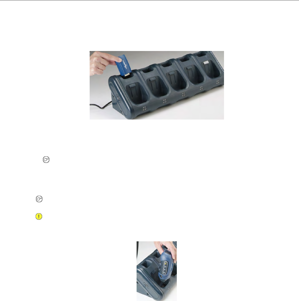
Charging an A500 or T5-Series Battery
1. Remove the battery from the Talkman device.
2. Hold the battery with its contacts to the bottom and the Vocollect label facing you.
Figure 34: Inserting a Battery Into the Charger
3. Place the battery into an open battery slot on the top level of the charger.
When the battery is placed into the charger properly, the left LED indicator for the slot into which
the battery was placed turns red.
Note: The upper set of LED indicators apply to the charger's battery slots and the lower indicators
apply to the devices' slots.
Removing an A500, T2-Series or T5-Series Device From a Charger
Note: The device is ready to use when the LED indicator on the device is blinking green. If the LED
is blinking red, the device is not ready to be used.
Important: If a device continuously displays a solid red light, contact your system administrator.
1. Make sure that the device is ready to use.
2. Pull up on the device to remove it from the device charger.
Figure 35: Removing a Device from a Charger
Inserting a Battery into a Talkman A500, T5-Series or T2-Series Device
Make sure the battery to be inserted is fully charged.
1. Hold the Talkman so that the red and yellow ports are facing away from you.
Confidential: For informational use by Vocollect Resellers and customers only
62 | Vocollect Hardware Documentation
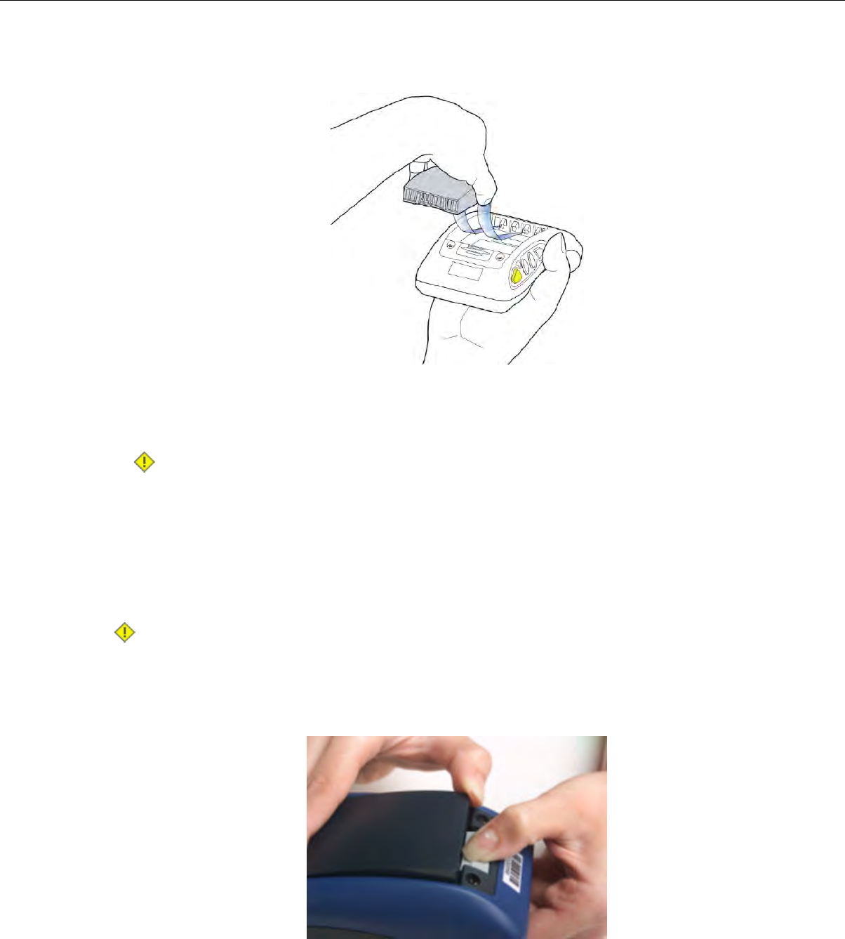
2. Hold the battery with the pins facing away from you and so that the Vocollect logo is on top.
3. Place the battery in at an angle, pins end first.
Figure 36: Properly Inserting a Battery
4. Push the back of the battery into place.
You will hear a click when the battery is in place.
Caution: Do not force the battery into the compartment. You may damage the battery or the
device. If the battery does not snap easily into place, reposition the battery in the compartment
and try again.
Make sure the battery is firmly in place and can't be removed without pressing the battery release button.
Removing a Battery from a Talkman A500, T5-Series or T2-Series Device
Make sure the Talkman device is off.
Caution: Do not remove the battery until the LED indicator is off. If you remove the battery when
the device is on or sleeping, any data collected could be lost.
1. Hold the device in one hand with the battery compartment facing toward you.
2. Press the battery release button all the way down until the top of the battery pops up from the battery
compartment.
Figure 37: Removing the Battery From a Device
3. Lift the battery out of the compartment.
Confidential: For informational use by Vocollect Resellers and customers only
Talkman T5 Series | 63

Battery Warm-Up Time
If a battery has been used in a cold environment, it will not begin charging until it warms up sufficiently.
Approximate warm-up timeTemperature of battery use
6 minutes-4°C (24.8°F)
10 minutes-10°C (14.0°F)
22 minutes-20°C (-4°F)
30 minutes-30°C (-22°F)
About LED Indicators
Vocollect Talkman devices, SRX and SRX2 headsets, and their chargers have LEDs that indicate the
state of the equipment. These LEDs may be on, off or blink. In some cases an LED will blink, alternating
between two colors.
If the LEDs indicate that there is a problem, refer to information on troubleshooting to solve the problem.
See also Troubleshooting Problems Indicated by LED.
T5-Series Device LED Indicators
T5-SeriesStateLED
Device is on
Also, one of the following:
On
Green
• adjusting volume
• sampling noise
• retraining a word
• changing the active operator
• after speaking:
• "Talkman help"
• "Talkman repeat"
• "Talkman continue"
• "Talkman backup"
The device is in a chargerFast Blink
One of the following:Slow Blink
• the device is in sleep mode and not in a charger
• the voice application selection menu is in use
• certain portions of software are loading
Device is turning on
Device is turning off
On Briefly
Red
Error, contact system administratorOn Continuously
Confidential: For informational use by Vocollect Resellers and customers only
64 | Vocollect Hardware Documentation
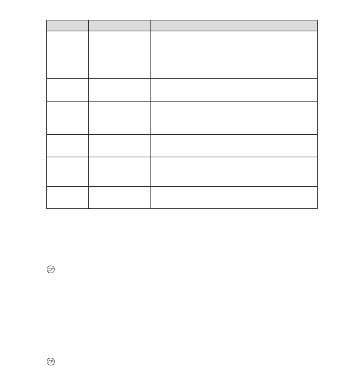
T5-SeriesStateLED
One of the following:Blinking
• retrieving and loading an operator from VoiceConsole
• retrieving, reading and loading a voice application from
VoiceConsole
• certain portions of software are loading
Wi-Fi off
T5-Series Only
Off
Amber/Yellow
One of the following for T2-Series only:Slow Blink
• the device cannot contact VoiceConsole while in the charger
• the easy charger configuration is incorrect
The device's Wi-Fi connection is active
T5-Series Only
Random Blinking
Pattern
Bluetooth off
T5-Series Only
Off
Blue
(Bluetooth
indicator)
The device's Bluetooth connection is active
T5-Series Only
Random Blinking
Pattern
Pairing an A500 or T5 Device and a Bluetooth Device
You can associate one Bluetooth®printer and/or one Bluetooth bar code reader to the same A500 or
T5-series device. You cannot associate multiple printers or bar code readers to a single Talkman device.
Note: You can also associate a Pidion®BM-170 display with an A500 device.
Pairing with the Honeywell MS9535: Talkman Device Is the Initiator
1. In VoiceConsole, follow the instructions for creating a pairing and setting the bar code scanner as
the acceptor. See VoiceConsole's Help for details.
2. Scan the Code 128 bar code (3000CA7000000). See the documentation that came with the Honeywell
9535 for details.
3. Place the Talkman device and bar code reader close together. The Talkman device associates with
the bar code reader. A low-tone/high-tone beep from the bar code reader indicates a successful
association.
Note: If a bar code reader goes out of communication range with the Talkman device, it may un-pair
from the Talkman device. You will hear a high-tone/low-tone beep. Move the bar code reader closer
to the Talkman to reassociate the bar code reader with the Talkman device. You will hear a
low-tone/high-tone beep when they pair.
Confidential: For informational use by Vocollect Resellers and customers only
Talkman T5 Series | 65

Pairing with the Honeywell MS9535: Talkman Device Is the Acceptor
The Talkman A500 and T5 devices must be configured in VoiceConsole to listen for incoming connections
before proceeding with these instructions. See the VoiceConsole online help for details.
For a T5 device, you must set the parameter Bluetooth_IsDiscoverable=true in the device properties in
VoiceConsole so that the device will broadcast its address.
Important: Only one scanner should be configured to communicate with a Talkman device's
Bluetooth address at any one time. If you change the bar code reader to which the device has been
paired, you must clear the Bluetooth service in the old bar code reader. Scan the Provide Bluetooth
Service bar code (3000CA7000000). See the documentation that came with the Honeywell scanner
for details.
1. With the Honeywell scanner, scan the Provide Bluetooth Service bar code (3000CA7000000). See the
documentation that came with the Honeywell scanner for details.
2. Power off the Talkman device completely and then power it back on.
3. Place the Talkman device into sleep mode or wait for it to enter sleep mode.
The green LED on the device blinks green.
4. Wait for 30 seconds.
5. Scan the Get Bluetooth Address bar code (3000CA7FFFFFF) from the Honeywell user's guide.
6. Scan the bar code on the Talkman device. This bar code contains the Talkman device's Bluetooth
address.
You will hear a quick, three-beep confirmation from the bar code reader, followed by a
low-tone/high-tone beep indicating success.
Pairing with Zebra QL Series Printers
For Bluetooth pairing:
• In VoiceConsole, find the device and use the appropriate action link to pair it to a peripheral.
• See VoiceConsole Help for detailed instructions on pairing devices.
• Create the pairing with the Zebra®QL™Series printer.
Pairing with Intermec PB50 Printers
Please refer to Intermec documentation on configuring the PB50 for Vocollect applications.
For Bluetooth pairing:
• In VoiceConsole, find the device and use the appropriate action link to pair it to a peripheral.
• See VoiceConsole Help for detailed instructions on pairing devices.
• Create the pairing with the Intermec®PB50 mobile printer.
For Wireless Network (WiFi) pairing:
• In VoiceConsole, find the device and use the appropriate action link to pair it to a peripheral.
• Enter the printer's Pairing Name, Host, and Port.
The default TCP/IP port for the PB50 printer is 9100.
• See VoiceConsole Help for detailed instructions on pairing devices.
Pairing the Honeywell LXE 8652 Scanner: Talkman Device Is the Initiator
During use, it is possible for the scanner to disconnect from the device if the communication link is
disrupted. When the scanner is setup so that the device initiates the connection, the device typically
Confidential: For informational use by Vocollect Resellers and customers only
66 | Vocollect Hardware Documentation

recovers the connection automatically. When the scanner initiates the connection, it typically requires
the press of a button to activate and recover the connection..
This method of pairing is useful if a single Talkman T5 Series device will always be associated with one
scanner.
You must have access to VoiceConsole to set up the pairing. For production use, Vocollect recommends
that you create a specific device profile in VoiceConsole to store many of the following settings.
1. Print this page.
2. Scan the following barcode to ensure that the Honeywell LXE®8652 scanner is ready to accept a
connection, even if it was previously paired.
Caution: The scanner may not accept a connection if this barcode is not scanned.
Figure 38: Set Up Scanner as Slave
3. Using VoiceConsole, locate the specific Talkman T5 device to be paired with the scanner.
4. View the properties of the device, and ensure that Bluetooth is enabled. If it is not enabled, click Edit
this device and set Bluetooth Enabled to "enabled."
5. Select the Pair this device with a peripheral option.
6. For Pairing Type select "Bluetooth Scanner."
7. For Connection Mode select "Device initaties connection with peripheral."
8. In the Bluetooth Adress enter the Bluetooth MAC address of the scanner. This 12-character ID is
labeled "MAC ID" and is found on the side of the battery unit of the scanner.
9. Click Pair with peripheral to initiate pairing.
Pairing the Honeywell LXE 8652 Scanner: Scanner Is the Initiator
During use, it is possible for the scanner to disconnect from the device if the communication link is
disrupted. When the scanner is setup so that the device initiates the connection, the device typically
recovers the connection automatically. When the scanner initiates the connection, it typically requires
the press of a button to activate and recover the connection..
This method of pairing is useful if a scanner will be used with more than one Talkman T5 Series device.
You must have access to VoiceConsole to set up the pairing. For production use, Vocollect recommends
that you create a specific device profile in VoiceConsole to store many of the following settings.
1. Ensure that the Talkman is labeled with a code 128 barcode. This code contains the FNC3 code
followed by the capital letter "B" and the unique Bluetooth MAC address of the Talkman.
a) If the Talkman does not have a barcode label, generate the FNC3 on a PC with a full keyboard
and number pad. Hold the ALT key down and press the four-number sequence "1 0 7 9" on the
number pad. A small number 3 will appear to indicate the presence of the code. Some barcode
software packages have special insertion keystrokes for FNC3.
b) Find the Bluetooth MAC address of the Talkman on the rear of the device near the belt clip. The
address begins with "BT."
2. Print this page.
Confidential: For informational use by Vocollect Resellers and customers only
Talkman T5 Series | 67

3. Using VoiceConsole, locate the specific Talkman T5 device to be paired with the scanner.
4. View the properties of the device, and ensure that Bluetooth is enabled. If it is not enabled, click Edit
this device and set Bluetooth Enabled to "enabled."
5. Select the Pair this device with a peripheral option.
6. For Pairing Type select "Bluetooth Scanner."
7. For Connection Mode select "Device listens for peripheral connection."
8. Click Pair with peripheral to initiate pairing.
9. To complete the pairing, scan the barcode created for the Talkman device in first step.
10. When finished using the Talkman and scanner, unpair the Talkman by scanning the following barcode
to set the scanner to slave mode.
Note: Performing this step ensures that the scanner does not generate spurious Bluetooth RF
that could interfere with other transmissions.
Figure 39: Reset Scanner as Slave
Note: To pair the scanner again, rescan the Talkman code 128 barcode.
Pairing the Socket Cordless Ring Scanner with a Talkman T5
During use, it is possible for the scanner to disconnect from the device if the communication link is
disrupted. When the scanner is setup so that the device initiates the connection, the device typically
recovers the connection automatically. When the scanner initiates the connection, it typically requires
the press of a button to activate and recover the connection..
The Bluetooth connection between the Socket®Cordless Ring Scanner (CRS) and a Talkman T5 is
managed through VoiceConsole. See VoiceConsole Help for details on the use of Bluetooth with Vocollect
Voice systems.
Note that Each CRS has a unique Bluetooth address that is clearly labeled on the underside of the
wrist-worn Bluetooth transmitter and battery pack. This address is needed to associate a CRS with a
T5.
Because a T5 will be explicitly associated with a specific CRS via VoiceConsole, Vocollect strongly
recommends clearly labeling the CRS wrist units to identify them with the specific T5 to which they are
paired. A clear identification and operational procedure for keeping specific scanners associated with
specific Talkman T-Series devices will be beneficial in the work environment.
Connecting the CRS to the Talkman T5 Device
The Socket Cordless Ring Scanner, with scanner part number ending in REV D, can be paired with a
T5-series device where the scanner acts as the initiator.
You must have access to VoiceConsole to set up the pairing. For production use, Vocollect recommends
that you create a specific device profile in VoiceConsole to store many of the following settings.
1. In VoiceConsole, select Bluetooth scanner as the pairing type for the device you want to pair with
the scanner. For the Connection Mode, select Device listens for peripheral connection. See VoiceConsole
Help for details.
Confidential: For informational use by Vocollect Resellers and customers only
68 | Vocollect Hardware Documentation

2. Create a bar code using Symbology Code 128 in the following form, where AABBCCDDEEFF is the
Bluetooth MAC address found on the T5: #FNIAABBCCDDEEFF#
a) Bar codes can be created at a Web site such as www.barcoding.com/upc.
3. Turn on the Socket CRS and the T5.
4. Scan the bar code you created.
The scanner beeps and begins flashing rapidly. It is now searching for the device.
5. Place the scanner and device closely together to pair.
The Bluetooth LED on the scanner blinks once every four seconds to indicate that the scanner and
device have paired.
Installing an A500 or T5-Series Device Into a Vehicle
A Talkman A500/T5 VMT Mobile Computer, is an A500 or T5-Series device with a battery adapter
mounted to a vehicle, such as a forklift or motorized pallet jack. After the device is mounted, the battery
adapter is placed in the battery area of the A500 or T5-Series device (connected to the vehicle’s power
source).
Talkman devices in this configuration may use any wired or wireless equipment (headsets, scanners,
etc.). Vocollect sells the complete solution including mounting kits and power systems to enable any
Talkman A500 or T5-Series devices to be used in an A500/T5 VMT configuration.
Caution: PLEASE DO NOT LOOK AT DEVICE/UNIT WHILE OPERATING MACHINERY SO
AS TO AVOID CREATION OF A DISTRACTION THAT COULD RESULT IN AN ACCIDENT AND
BODILY INJURY TO OPERATOR AND THIRD PERSONS.
Follow the instructions below to properly install the device in a forklift.
• Determine the best location for mounting the device, taking into consideration the driver’s field of
view.
• Install the appropriate mounting hardware.
• Connect the device to the vehicle’s wiring system.
Talkman A500/T5 VMT Mobile Computer Accessories
The Talkman A500/T5 VMT Mobile Computer is designed to be installed using RAM Mounting Systems
hardware. Vocollect supplies a mounting bracket for the A500/T5 and mounting hardware from RAM
Mounting Systems. Additional hardware mounting bracket options can be purchased directly from RAM
Mounting Systems (www.ram-mount.com) to customize the installation.
The A500/T5 VMT must be mounted to a sturdy surface.
Confidential: For informational use by Vocollect Resellers and customers only
Talkman T5 Series | 69
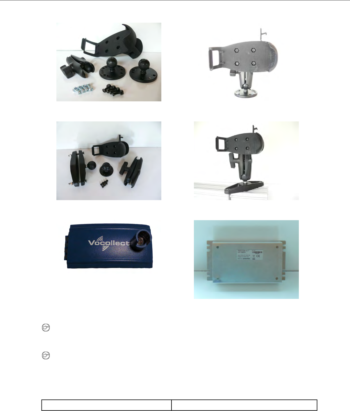
Figure 41: Screw On MountingFigure 40: Screw On Mounting Parts
Figure 43: Clamp MountingFigure 42: Clamp Mounting Parts
Figure 45: Power Supply
Figure 44: Battery Adapter
Note: You may provide your own power supply, but it must supply 12-15V at 1 Amp and must be
limited to less than 250VA (Watts). If you chose to provide your own, you are still required to purchase
the battery adapter cable and battery adapter for final connection to the A500 or T5-Series device.
Note: This configuration does not require you to connect the A500 or T5-Series device to the vehicle's
power source. If desired, for operational reasons, T5-Series devices may be used in VMT configuration
using a Vocollect battery.
Talkman A500/T5 VMT Mobile Computer Accessory Specifications
-30° to 50° C (-22° to 122° F)Operating Temperature
Confidential: For informational use by Vocollect Resellers and customers only
70 | Vocollect Hardware Documentation
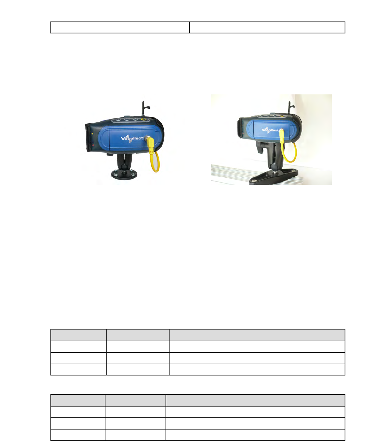
-40° to 70° C (-40° to 158° F)Storage Temperature
Mounts for Talkman A500/T5 VMT Mobile Computers
The Screw On Mount is a mounting option that is bolted to a stationary surface on a vehicle.
The Clamp Mount is a mounting option that is clamped to a stationary surface on a vehicle. This can
also be bolted to a stationary surface, if desired.
Figure 47: Clamp MountFigure 46: Screw On Mount
Positioning the Talkman A500/T5 VMT Mobile Computer
• Determine the best position for the device and all the associated components. If a similar device was
previously installed, check to see if the position it used is suitable for the device.
• Test the installation for at least 30 minutes before installing on another vehicle. Record all details:
• Check that the position of the device does not obstruct vehicle controls.
• Check that the device does not obstruct the driver's view.
• Check the position of the device for user comfort over long periods.
Installing the Mounting Brackets for a Talkman A500/T5 VMT Mobile Device
The following parts are supplied by Vocollect for attaching the screw on mount:
DescriptionQuantityItem #
Vehicle Mount, Holder/Base Screw On Attachment21
Vehicle Mount, Arm12
Vehicle Mount, Holder13
The following parts are supplied by Vocollect for attaching the clamp on mount:
DescriptionQuantityItem #
Vehicle Mount, Clamp11
Vehicle Mount, Arm12
Vehicle Mount, Holder13
Confidential: For informational use by Vocollect Resellers and customers only
Talkman T5 Series | 71
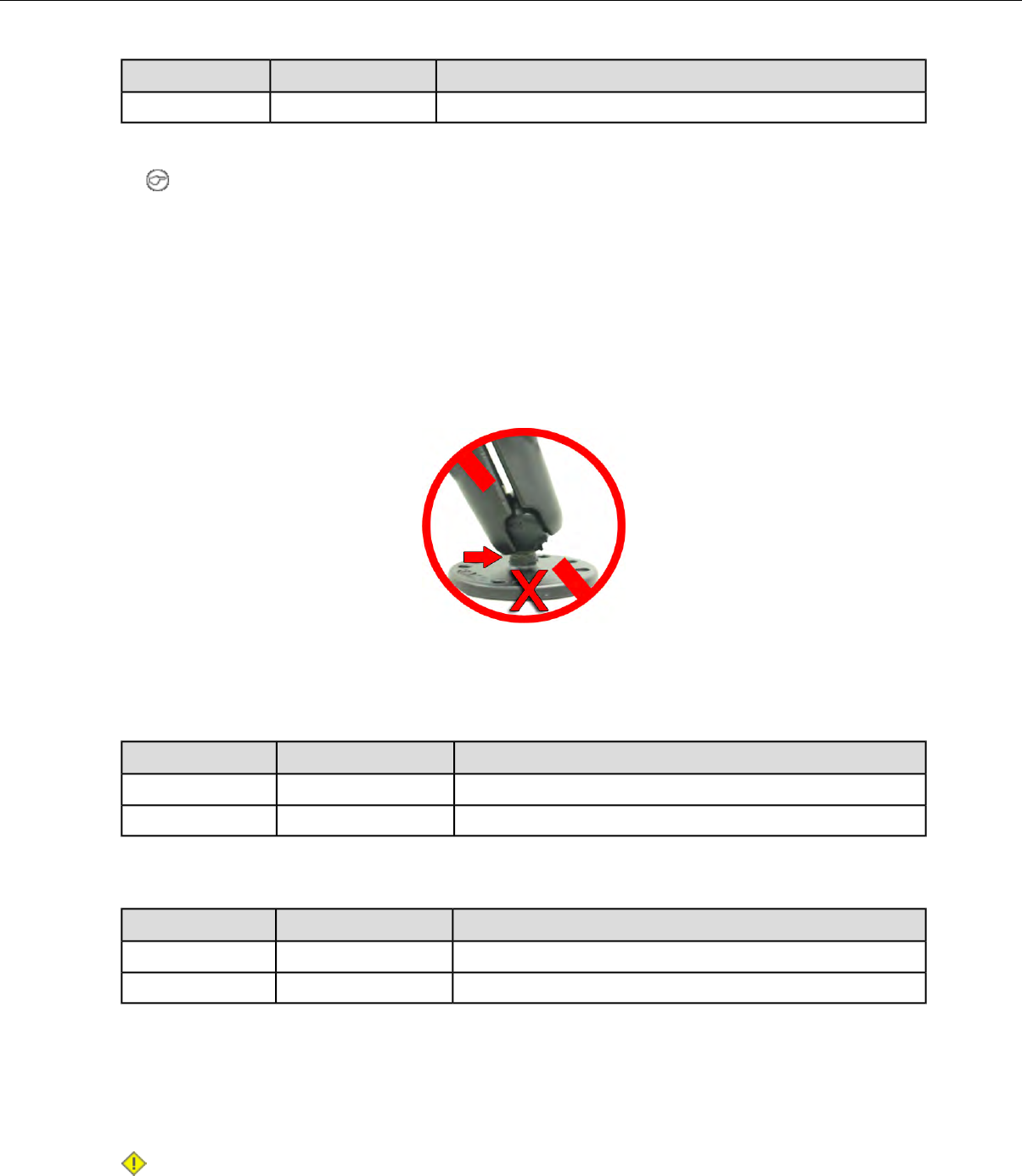
DescriptionQuantityItem #
Vehicle Mount, Holder/Base Screw On Attachment14
1. Drill the holes required to secure the base to the vehicle. If using the clamp mount, skip this step.
2. Note: Apply some lubricant (for example, light oil or anti-sieze) to the threads of the clamp
mount screws.
Screw or clamp a base to the location.
3. Attach the other base to the other end of the arm and tighten once in the desired location by turning
the locking lever clockwise.
4. Screw the device holder to the base.
5. Insert a device into the holder, and insert the battery adapter into the device.
6. Attach the cable from the power supply to the battery adapter.
To prevent vibration, the arm of the mounting bracket should not touch the stem of the ball of the base.
In other words, the arm should not be tilted so far as to have these pieces touching.
Connecting Cables to the Power Supply and Attaching the Power Supply to a Vehicle
The following parts are supplied by Vocollect for attaching the 12 or 24 volt vehicle's power supply to a
device:
DescriptionQuantityItem #
Power Supply, 9-36 VDC Input11
Cable from power supply to battery adapter12
The following parts are supplied by Vocollect for attaching the 36 or 48 volt vehicle's power supply to a
device:
DescriptionQuantityItem #
Power Supply, 18-60 VDC Input11
Cable from power supply to battery adapter12
You will need the following equipment:
• One Cable from the power supply to vehicle’s power source. Vocollect recommends an industrial rated
cable with the following specifications: Number of conductors = 3, Gauge of wire = 16, Temperature
= -40C to 90C
• Cable ties
Caution: General Guidelines for Routing Electrical Cables
• The vehicle must be off and the vehicle's battery must be disconnected.
Confidential: For informational use by Vocollect Resellers and customers only
72 | Vocollect Hardware Documentation

• Cables should be kept clear of surfaces that may become hot.
• Cables should not be run such that they can get caught on moving parts.
• Cables should not be run on the outside of a vehicle.
• Cables should not have 90 degree turns, the minimum bend radius should not be less than one
inch
• To remove slack on a cable it should be coiled up and secured inside the vehicle with a cable tie.
• For maximum safety fuses should be located as close as possible to the power source.
• To protect the A500/T5 VMT from power surges and to perform voltage conversion a converter
module is fitted between the A500/T5 VMT and the forklift battery.
1. Disconnect the vehicle battery.
2. Remove the four screws from the top of the power supply to expose the screw terminals.
3. On the cable from power supply to the vehicle’s power source, strip the three cables to expose
approximately 5mm of copper. Ensure the cable is long enough to reach from the power supply to the
vehicle’s power source.
4. On the yellow cable from the battery adapter to the power supply, strip the black and brown cable to
expose approximately 5mm of copper. The Blue cable is not required; it can be trimmed where it exits
the yellow cable. Ensure the cable is long enough to reach from the power supply to the vehicle’s
power source.
5. Connect the cables from the battery adapter to the power supply by performing the steps below.
• Loosen the screws to where the connection will be made on the power supply.
• Match the cables to the correct locations as indicated in the chart below:
•Output ConnectorCable
+Brown – Battery Adapter Positive
-Black – Battery Adapter Negative
GNDNo connection needed
Not applicableBlue (cut back)
• Tighten the screws.
• Ensure the cables are secure
6. Connect the cables from the vehicle’s power source to the power supply by performing the steps below:
• Loosen the screws to where the connection will be made on the power supply.
• Match the cables to the correct locations as indicated in the chart below:
•Input ConnectorCable
+White (may differ depending on the cable) – Vehicle Positive
-Black (may differ depending on the cable) – Vehicle Negative
GNDGreen - Vehicle Ground
• Tighten the screws.
• Ensure the cables are secure
7. Once all of the cables have been successfully installed, attach cable ties to secure the cables.
Confidential: For informational use by Vocollect Resellers and customers only
Talkman T5 Series | 73
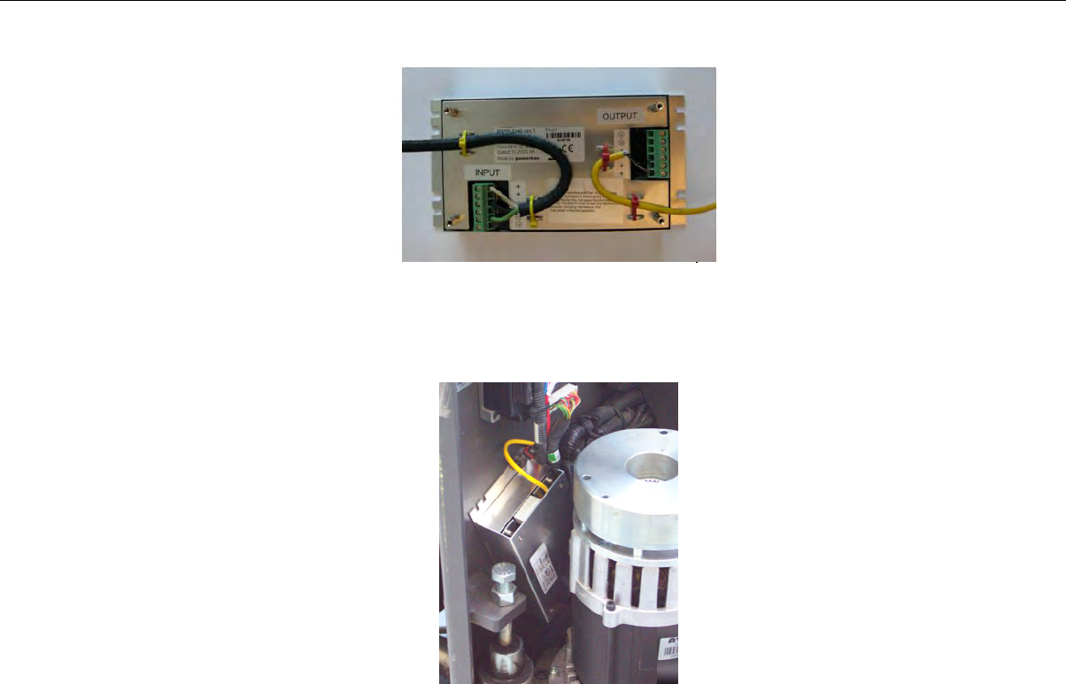
Figure 48: Cables Attached to the Power Supply
8. Place the power supply in a place out of the way, such as under the dashboard of a fork lift, and attach
it to a secure surface with cable ties. Alternatively the power supply could be secured by bolting it
using the mounting slots.
Figure 49: Power Supply Attached to a Secure Surface on the Vehicle
9. Run the cable that connects the battery adapter to the power supply from the power supply to the
location where the A500/T5 VMT will be mounted
10. Connect the yellow wire to the battery adapter by attaching the connector and tightening the nut.
Connecting the Talkman A500/T5 VMT Mobile Computer to a Vehicle's Power Source
You will need the following equipment:
• Two fuse holders from Cooper Bussman. Vocollect recommends using a Cooper Bussmann HFA series
in line waterproof fuse.
• Two fuses. Vocollect recommends a 2A 250V SLO BLO fuse.
• Three spade connectors
• Four small cable ties
• Fasteners
Vocollect recommends choosing unswitched power as the source for the power supply. This will allow
Talkman devices to be powered for software updates as well as prevent Talkman devices from accidentally
being unpowered if the vehicle is quickly switched off unintentionally.
1. Remove all power sources from the vehicle.
2. Remove any excess length from the cable from the input cable from the power supply.
3. Connect the fuses to the cable near to the battery end of the cable. Remove approximately 4 inches
of the outer insulation from the cable.
Confidential: For informational use by Vocollect Resellers and customers only
74 | Vocollect Hardware Documentation
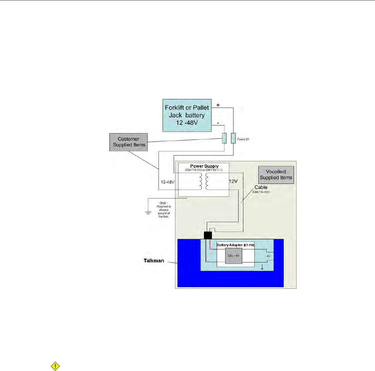
4. Expose approximately 10mm of copper on the positive and negative wires.
5. Insert the exposed copper into the fuseholders and crimp into the positive and negative wires using
an approved tool.
6. Connect the green wire to the vehicle's ground.
7. Connect the fused white wire to the vehicle’s positive power source using an appropriate connector.
This may need to be crimped onto the wire.
8. Connect the fused black wire to the vehicle’s negative power source using an appropriate connector.
This may need to be crimped onto the wire.
9. Attach the power supply as shown in the following diagram.
Figure 50: Attach the Power Supply
10. Secure the wires with cable ties.
Removal of Talkman A500/T5 VMT Mobile Computer from Vehicle
Talkman A500/T5 VMT mobile computer components are designed for easy removal for occasional vehicle
service, maintenance or flexible operational needs.
Caution: Vocollect does not recommend removing the cables (CM-710-101, CM-710-102) from the
battery adapter except when required for occasional service (i.e. once per month at maximum)
Excessive removal of these cables may damage the adapter and cable. This type of use is not covered
under warranty or service plans as it is unintended product use that is specifically not recommended.
1. Release the battery adapter from the device.
2. Dock the battery adapter in the side of the VMT holder.
This leaves the device free to be removed and the battery adapter and cable docked and protected.
Confidential: For informational use by Vocollect Resellers and customers only
Talkman T5 Series | 75
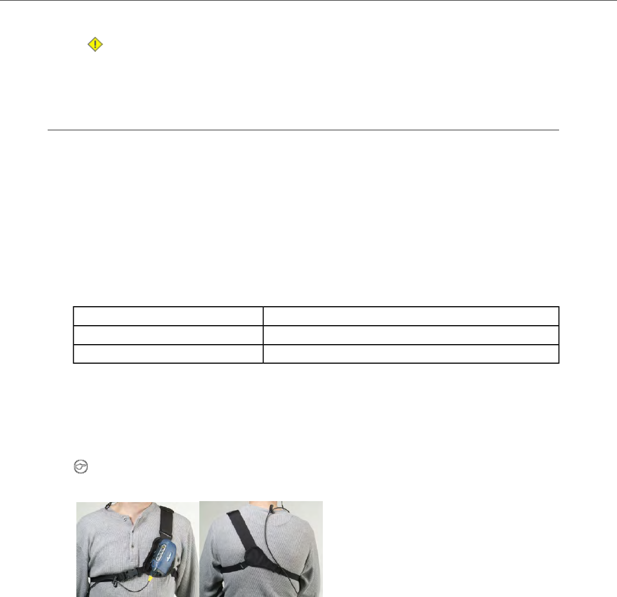
Caution: The battery adapter should remain cabled and docked when not in use to prevent cable
damage or accidental contact of the adapter contacts with metal surfaces.
Accessories
Vocollect offers a variety of accessories for wearing, protecting, and facilitating the operations of Talkman
and other handheld devices.
T5/A500 Adjustable Shoulder Harness
Operators wear devices on an adjustable shoulder harness that is purchased from Vocollect. The device
is attached to the shoulder harness with a specially designed clip.
Operators must regard the clip and the device as two separate entities. The clip should be attached to
the Vocollect shoulder harness at the beginning of a shift. Then, the operator can attach the device to
and remove the device from the clip as often as necessary throughout the shift.
T5/A500 Adjustable Shoulder Harness Specifications
2" (5 cm) Wide Adjustable NylonShoulder Strap
Two Adjustable Elastic Nylon, 32"-48"(81 cm - 122 cm)Chest Straps (Regular)
Two Adjustable Elastic Nylon, 41"-66" (104 cm - 167 cm)Chest Straps (Large)
Putting a Device on a T5/A500 Shoulder Harness
To mount a device onto the specially designed belt or shoulder harness, an operator must have a slim
belt clip (provided with the belt or harness). The clip should be attached to the belt at the beginning of
a shift. Then, the operator can attach the device to and remove the device from the clip as often as
necessary.
Note: Vocollect strongly recommends that the device be worn on the right side of the body with the
device's buttons on the top and its connectors toward your back.
Figure 51: T5/A500 Shoulder Harness Properly Worn - Front and Back Views
1. Open the flap on the front of the shoulder harness by unsnapping the two buttons.
2. Slide the flap through the slots on the belt clip.
3. With the clip all the way on the flap, snap the buttons together.
4. Unbuckle the large loop.
5. Put your left hand through the small loop and slide the harness over your left shoulder.
6. Clip the large loop in front of your chest.
Confidential: For informational use by Vocollect Resellers and customers only
76 | Vocollect Hardware Documentation

7. Adjust the straps.
8. Connect the device to the shoulder harness clip by sliding the device onto the clip until it snaps into
place.
The device is properly clipped in place if you cannot remove it from the clip without pressing the device's
clip release button.
Belts and Belt Clips
Figure 52: Belt with Clip
Operators wear devices on a customized belt that is purchased from Vocollect. The device is attached to
the belt with a specially designed clip or holster.
The clip is attached to the Vocollect belt at the beginning of a shift. The operator can attach the device
to and remove the device from the clip as often as necessary throughout the shift. Vocollect sells three
types of mounting clips:
• T2 Series Slim Blue Belt Clip: connects a devi ceto the customized belt.
• T2 Series Heavy Duty Belt Clip: adapts an OPEN belt (sold with Vocollect's previous device) for use
with a T2 Series device.
• T5/A500 Black Belt Clip: connects a T5 or A500 device to the belt.
• To comply with government safety standards, the device must be used with either a Vocollect
customized belt and clip, a Vocollect customized shoulder harness, or a Vocollect belt holder.
• Vocollect strongly recommends that the device be worn on the right side of the body with the device’s
buttons on the top and its connectors toward your back.
Using the T-Series Belts and Clips
To mount a device onto the specially designed belt or shoulder harness, an operator must have a slim
belt clip (provided with the belt or harness). The clip should be attached to the belt at the beginning of
a shift. Then, the operator can attach the device to and remove the device from the clip as often as
necessary.
• A500 and T5-series devices can be worn on a belt or shoulder harness.
Confidential: For informational use by Vocollect Resellers and customers only
Talkman T5 Series | 77
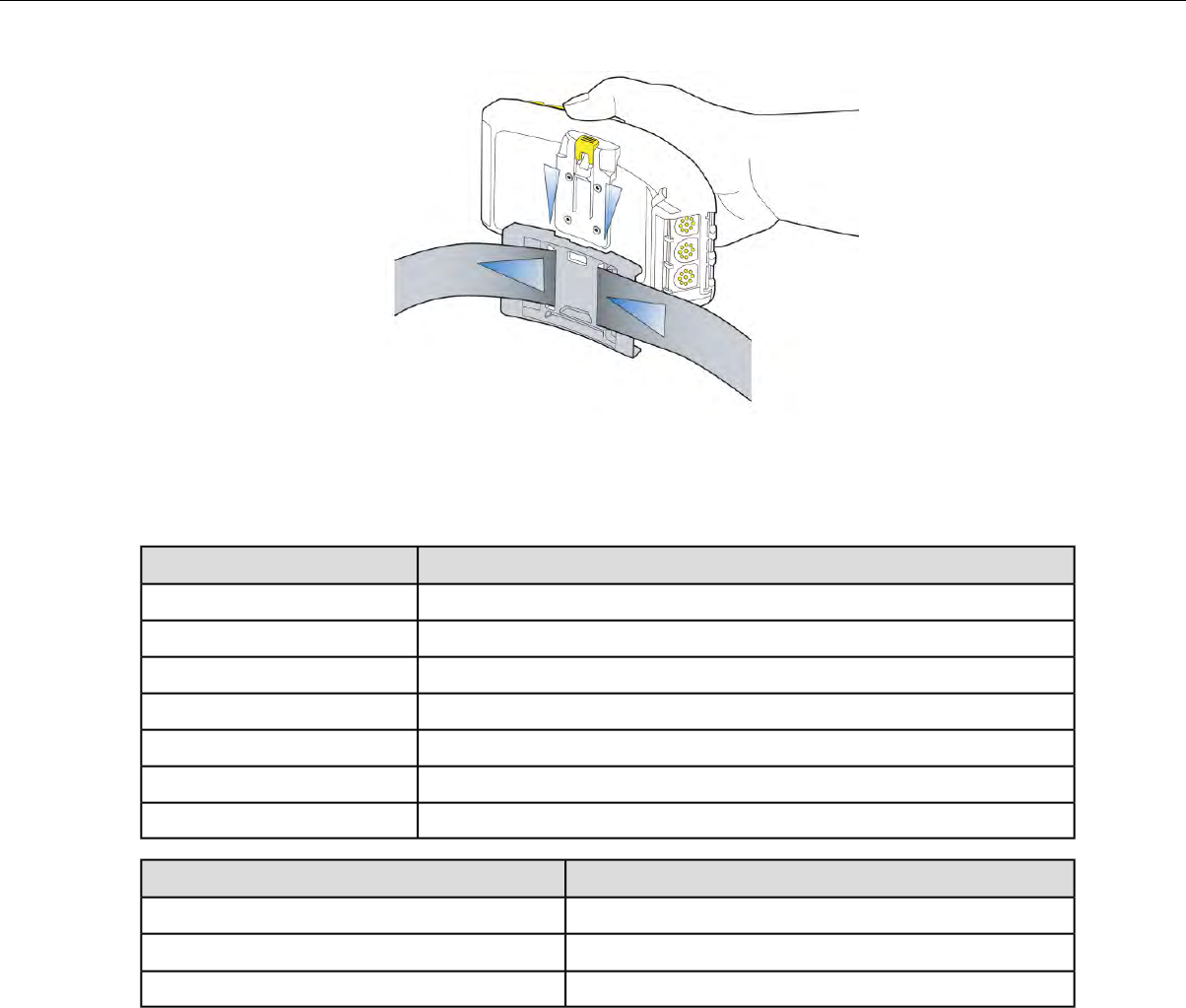
Figure 53: Attaching the Device to a Belt Clip
T-Series Belt Specifications
DimensionsBelt Size
18" - 26" (46cm-66cm)XS
24" - 32" (61cm-81cm)S
28" - 36" (71cm-91cm)M
34" - 42" (61cm-107cm)L
40" - 48" (102cm-122cm)XL
46" - 54" (117cm-137cm)XXL
52" - 60" (132cm-152cm)XXXL
SpecificationBelt Part
NylonBelt material
YKK Hook and LoopVelcro®
ITW Nexus 127-3200Belt fastener
Device Covers
Vocollect offers an optional protective covers for its devices.
• The use of a device cover is not required; however, Vocollect strongly recommends using the cover to
help preserve the appearance and prolong the life of the devices.
• Using the protective cover in a freezer environment prolongs battery life.
Confidential: For informational use by Vocollect Resellers and customers only
78 | Vocollect Hardware Documentation

Figure 54: A500/T5 Elastomer-SKIN Cover
• The device cover does not have to be removed before placing the device into a device charger.
• The EXO Skeleton Cover provides additional drop protection for the device, is easy to remove, and
permits full access to all device features and functions.
Figure 55: T2-Series Device Cover
• You must remove the device cover before placing the device into a device charger. Failure to do so
could result in damage to both the device and the charger.
T5/A500 Elastomer-SKIN Cover Specifications
ThermoPlastic Elastomer (Dynaflex G2755)Fabric
Putting a Cover on an A500 or T5-Series Device
1. If the device is not already off, press and hold the yellow play/pause button until the LED indicator
turns solid red and then off.
2. Disconnect any peripherals.
3. Hold the device with the battery compartment facing up and the device's buttons facing toward you.
4. Slide the open end of the cover over the connection port end of the device. Pull gently on the cover to
make sure it slides behind the tab, located on the bottom of the device, that holds the cover securely
in place.
Confidential: For informational use by Vocollect Resellers and customers only
Talkman T5 Series | 79

Figure 56: Putting a Cover on a Talkman T5-Series Device
5. Stretch the rounded end of the cover over the rounded end of the device.
6. Attach the peripherals that you will be using.
Confidential: For informational use by Vocollect Resellers and customers only
80 | Vocollect Hardware Documentation
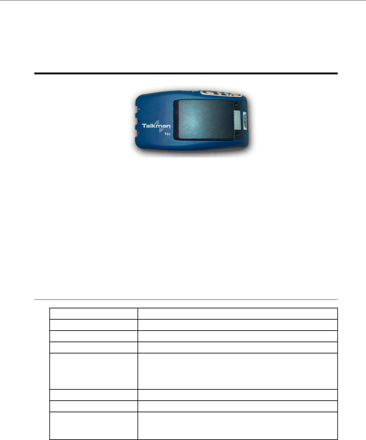
Chapter 5
Talkman T2 Series
Figure 57: Talkman T2x
The Talkman®T2x is a rugged voice-enabled device that performs to military and international standards.
It can withstand the potential impacts, rough handling, water exposure, and corrosive conditions of
industrial environments.
Talkman T2-Series Features
• Wi-Fi network support and ample memory to continue operations during breaks in RF coverage
• Standard and high-capacity battery options meet the varying needs of different warehouses
• High-performance battery ensures uninterrupted power even in freezing conditions
• Ergonomic design and rugged belt clip provide user comfort and easy access
• Four-button interface enables easy user interaction
• Two connection points accommodate peripherals such as scanners or printers
T2 Series Specifications: Talkman T2xand Talkman T2
16 ounces (with standard battery) (453 g)Weight
6.5" (16.5 cm)Length
3.38" (8.5 cm)Width
1.5" (4 cm)Depth
I/O Ports • Headset port (yellow)
• Maintenance port with audio out and RS-232 serial support (red)
• Bar code port with RS-232 decoded bar code support (blue)
-22° to 122° F (-30° to 50° C)Operating Temperature
-30° to 140° F (-34° to 60° C)Storage Temperature
Meets the MIL STD -810F specification for shock and vibration.
Drop Tested
In addition, the device has been tested to the following specifications:
Confidential: For informational use by Vocollect Resellers and customers only
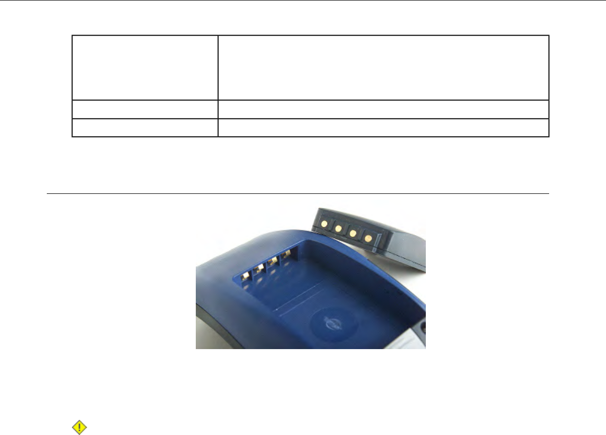
• 25 drops from 5 feet (152.4 cm)
• 10 additional drops from 6 feet (182.88) onto polished concrete
•10 drops at varying angles from 5 feet at -20° F (-29° C) onto polished
concrete
100% condensingHumidity
IP67Enclosure Rating
Charging a T2-Series Device
Figure 58: Talkman T2 Series Battery
The T2 series battery is available in standard and high-capacity models. The standard battery sits flush
with the top of the device when installed. The high-capacity battery has a longer run time than the
standard capacity battery.
Caution: T2 series and A500/T5 series batteries are not interchangeable. If you try to insert the
wrong battery into a device, you may damage the device and the battery.
The T2-Series battery is designed to be charged while still seated in the device.
T2 Series High Capacity Battery Specifications
Electrical Specifications
• Cells: The high capacity battery pack uses four lithium ion cells.
• Nominal voltage = 7.2V
• Watt Hours = 27WHr (standard T2x battery is 14WHr )
• Protection circuit characteristics: The pack contains a protection circuit that prevents over and under
voltage conditions on the cells and protects the pack from damage as a result of a short circuit between
the positive and negative terminals of the battery.
• Thermistor: The battery pack contains a negative temperature coefficient thermistor. The charger
uses the voltage drop across the thermistor to determine that the battery pack is within the proper
charging temperature limits.
• Battery ID: The battery pack contains a Dallas Semiconductor DS2401 serial ID chip. In future
enhancements to both the device and the device software, this chip will be used to provide data about
features such as battery life, capacity monitoring and asset tracking.
• Battery Charging: The battery pack must only be charged in a Vocollect designated charger.
Confidential: For informational use by Vocollect Resellers and customers only
82 | Vocollect Hardware Documentation
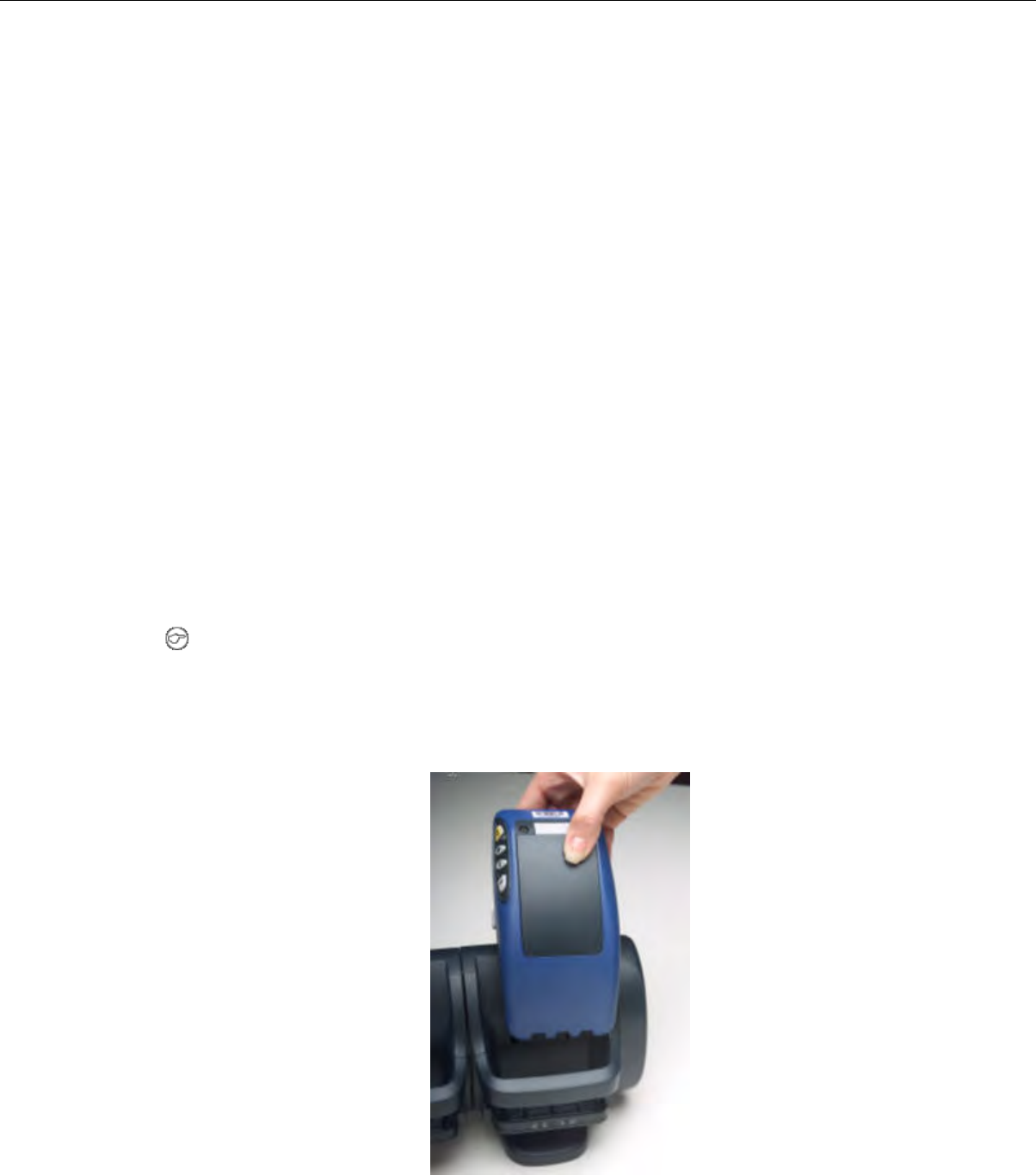
Mechanical and Environmental Specifications
• Drop-test specifications: The high capacity battery meets the MIL STD 810F specification for shock
and transient drop criteria.
• Environmental specifications: The battery pack halves are sonically welded together to protect the
internals from water and dust.
• The battery functions properly in the following conditions:
Temperature: -20°C to 50°C (-4°F to 122°F)
Humidity: 95% non-condensing
Rain/dust: IP67
Battery Notifications
Battery warnings for a Talkman battery occur at the following levels:
• First warning = 3,550 mV
• Critical warning = 3,350 mV
Charging a T2 Series Device
1. Make sure the charger is powered. The charger's orange power light (LED indicator) is lit when the
charger is powered.
2. Sign off of the device if necessary.
3. Press and hold the yellow play/pause button until the LED indicator turns solid red and then turns
off.
Note: It is not necessary to turn the device off before placing it into the charger.
4. Remove the device from the belt clip.
5. Disconnect any other peripherals. If the device is in a cover, remove the cover.
6. Insert the device into one of the device charger slots with the button controls of the device to the top
and facing toward the left.
Figure 59: Inserting a T2 Series Device Into a Charger
Confidential: For informational use by Vocollect Resellers and customers only
Talkman T2 Series | 83
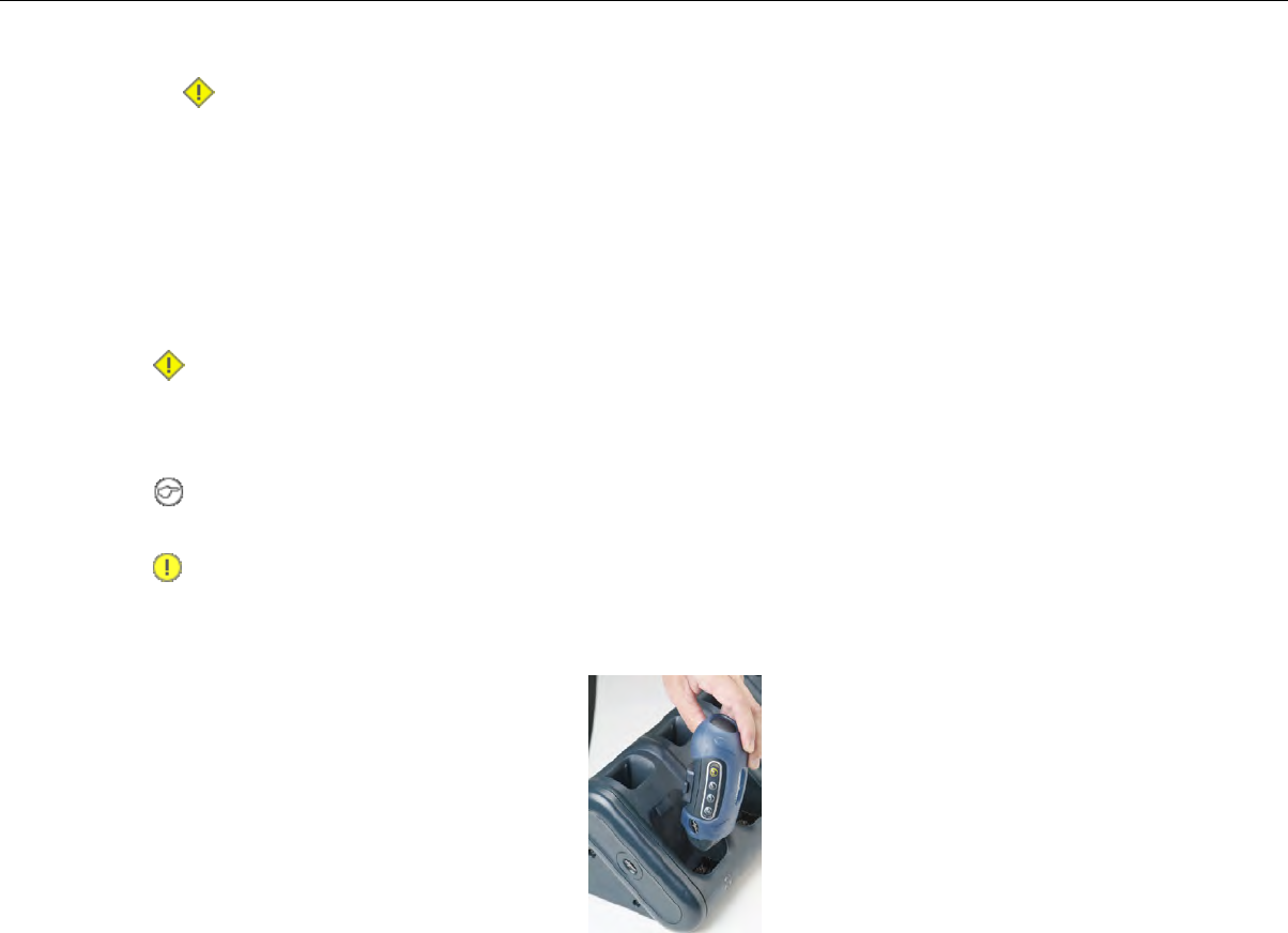
Caution: Do not attempt to place the device into the charger unless you have first disconnected
the headset and any other peripheral devices. Do not remove the battery from the device when
placing the device into a charger.
7. After the device has been placed into the charger, make sure that the LED indicator on the device
turns on and begins to blink green.
a) If the LED does not turn on after 30 seconds, remove the device from the charger slot and then
place it into the slot again.
b) If the LED indicator still does not turn on, try another charger slot.
Caution: If the LED indicator on a device is blinking red, do not remove the device from the charger.
Removing an A500, T2-Series or T5-Series Device From a Charger
Note: The device is ready to use when the LED indicator on the device is blinking green. If the LED
is blinking red, the device is not ready to be used.
Important: If a device continuously displays a solid red light, contact your system administrator.
1. Make sure that the device is ready to use.
2. Pull up on the device to remove it from the device charger.
Figure 60: Removing a Device from a Charger
Inserting a Battery into a Talkman A500, T5-Series or T2-Series Device
Make sure the battery to be inserted is fully charged.
1. Hold the Talkman so that the red and yellow ports are facing away from you.
2. Hold the battery with the pins facing away from you and so that the Vocollect logo is on top.
3. Place the battery in at an angle, pins end first.
Confidential: For informational use by Vocollect Resellers and customers only
84 | Vocollect Hardware Documentation
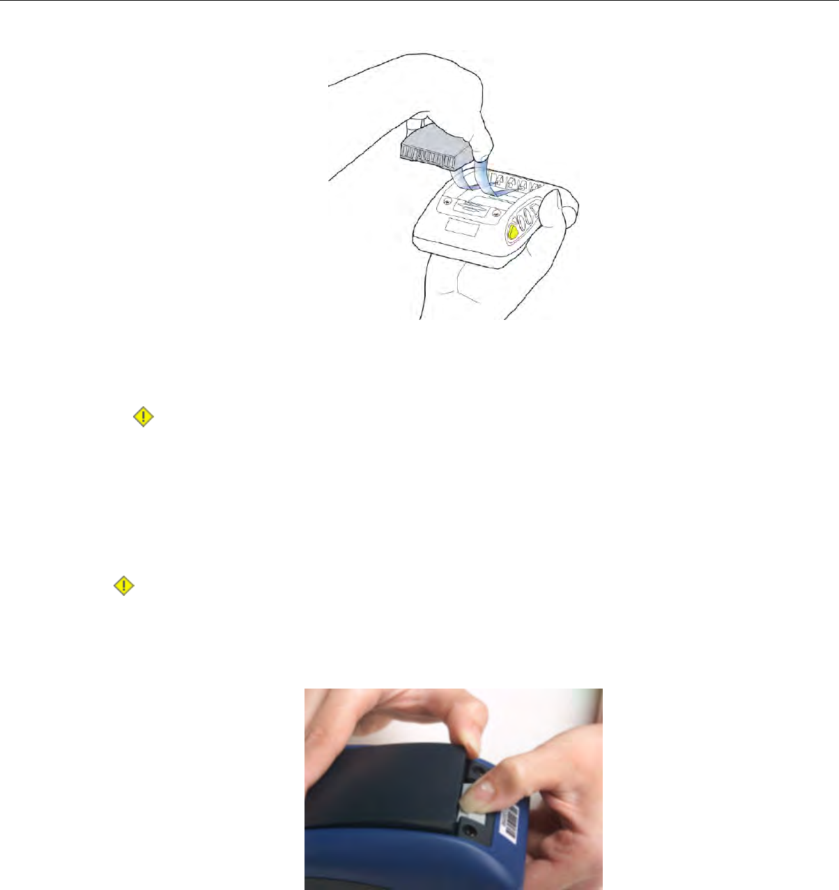
Figure 61: Properly Inserting a Battery
4. Push the back of the battery into place.
You will hear a click when the battery is in place.
Caution: Do not force the battery into the compartment. You may damage the battery or the
device. If the battery does not snap easily into place, reposition the battery in the compartment
and try again.
Make sure the battery is firmly in place and can't be removed without pressing the battery release button.
Removing a Battery from a Talkman A500, T5-Series or T2-Series Device
Make sure the Talkman device is off.
Caution: Do not remove the battery until the LED indicator is off. If you remove the battery when
the device is on or sleeping, any data collected could be lost.
1. Hold the device in one hand with the battery compartment facing toward you.
2. Press the battery release button all the way down until the top of the battery pops up from the battery
compartment.
Figure 62: Removing the Battery From a Device
3. Lift the battery out of the compartment.
Confidential: For informational use by Vocollect Resellers and customers only
Talkman T2 Series | 85

Battery Warm-Up Time
If a battery has been used in a cold environment, it will not begin charging until it warms up sufficiently.
Approximate warm-up timeTemperature of battery use
6 minutes-4°C (24.8°F)
10 minutes-10°C (14.0°F)
22 minutes-20°C (-4°F)
30 minutes-30°C (-22°F)
About LED Indicators
Vocollect Talkman devices, SRX and SRX2 headsets, and their chargers have LEDs that indicate the
state of the equipment. These LEDs may be on, off or blink. In some cases an LED will blink, alternating
between two colors.
If the LEDs indicate that there is a problem, refer to information on troubleshooting to solve the problem.
See also Troubleshooting Problems Indicated by LED.
T2-Series Device LED Indicators
T2-SeriesStateLED
Device is on
Also, one of the following:
On
Green
• adjusting volume
• sampling noise
• retraining a word
• changing the active operator
• after speaking:
• "Talkman help"
• "Talkman repeat"
• "Talkman continue"
• "Talkman backup"
The device is in a chargerFast Blink
One of the following:Slow Blink
• the device is in sleep mode and not in a charger
• the voice application selection menu is in use
• certain portions of software are loading
Device is turning on
Device is turning off
On Briefly
Red
Error, contact system administratorOn Continuously
Confidential: For informational use by Vocollect Resellers and customers only
86 | Vocollect Hardware Documentation

T2-SeriesStateLED
One of the following:Blinking
• retrieving and loading an operator from VoiceConsole
• retrieving, reading and loading a voice application from
VoiceConsole
• certain portions of software are loading
Device is attempting to get an IP address from the server. If unable
to get an IP, the device will turn off.
T2-Series Only
Alternating
Red/Green
One of the following for T2-Series only:Slow Blink
Amber/Yellow
• the device cannot contact VoiceConsole while in the charger
• the easy charger configuration is incorrect
Connecting a T2-Series with the Honeywell MS9535
1. Connect the scanner power cable to the Honeywell MS9535 VoyagerBT laser bar code scanner and
a power source.
2. If this is the initial use, allow the scanner to charge for several hours before use.
3. Set the Vocollect task with the following options: no parity, 9600 baud, 1 stop bit, CR/LF termination,
word length 8, and keep-power-on.
4. Use barcode software to generate a barcode for pairing the Vocollect T2x Bluetooth Serial Adapter
and Honeywell reader dynamically. Scanning this barcode will program the scanner to associate with
this specific serial adapter.
Note: If a bar code reader goes out of communication range with the Talkman device, it may un-pair
from the Talkman device. You will hear a high-tone/low-tone beep. Move the bar code reader closer
to the Talkman to reassociate the bar code reader with the Talkman device. You will hear a
low-tone/high-tone beep when they pair.
Accessories
Vocollect offers a variety of accessories for wearing, protecting, and facilitating the operations of Talkman
and other handheld devices.
Confidential: For informational use by Vocollect Resellers and customers only
Talkman T2 Series | 87
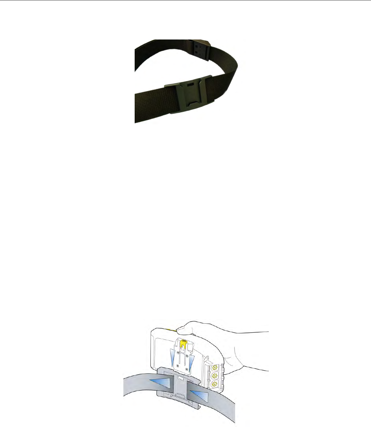
Belts and Belt Clips
Figure 63: Belt with Clip
Operators wear devices on a customized belt that is purchased from Vocollect. The device is attached to
the belt with a specially designed clip or holster.
The clip is attached to the Vocollect belt at the beginning of a shift. The operator can attach the device
to and remove the device from the clip as often as necessary throughout the shift. Vocollect sells three
types of mounting clips:
• T2 Series Slim Blue Belt Clip: connects a devi ceto the customized belt.
• T2 Series Heavy Duty Belt Clip: adapts an OPEN belt (sold with Vocollect's previous device) for use
with a T2 Series device.
• T5/A500 Black Belt Clip: connects a T5 or A500 device to the belt.
• To comply with government safety standards, the device must be used with either a Vocollect
customized belt and clip, a Vocollect customized shoulder harness, or a Vocollect belt holder.
• Vocollect strongly recommends that the device be worn on the right side of the body with the device’s
buttons on the top and its connectors toward your back.
Using the T-Series Belts and Clips
To mount a device onto the specially designed belt or shoulder harness, an operator must have a slim
belt clip (provided with the belt or harness). The clip should be attached to the belt at the beginning of
a shift. Then, the operator can attach the device to and remove the device from the clip as often as
necessary.
• A500 and T5-series devices can be worn on a belt or shoulder harness.
Figure 64: Attaching the Device to a Belt Clip
Confidential: For informational use by Vocollect Resellers and customers only
88 | Vocollect Hardware Documentation
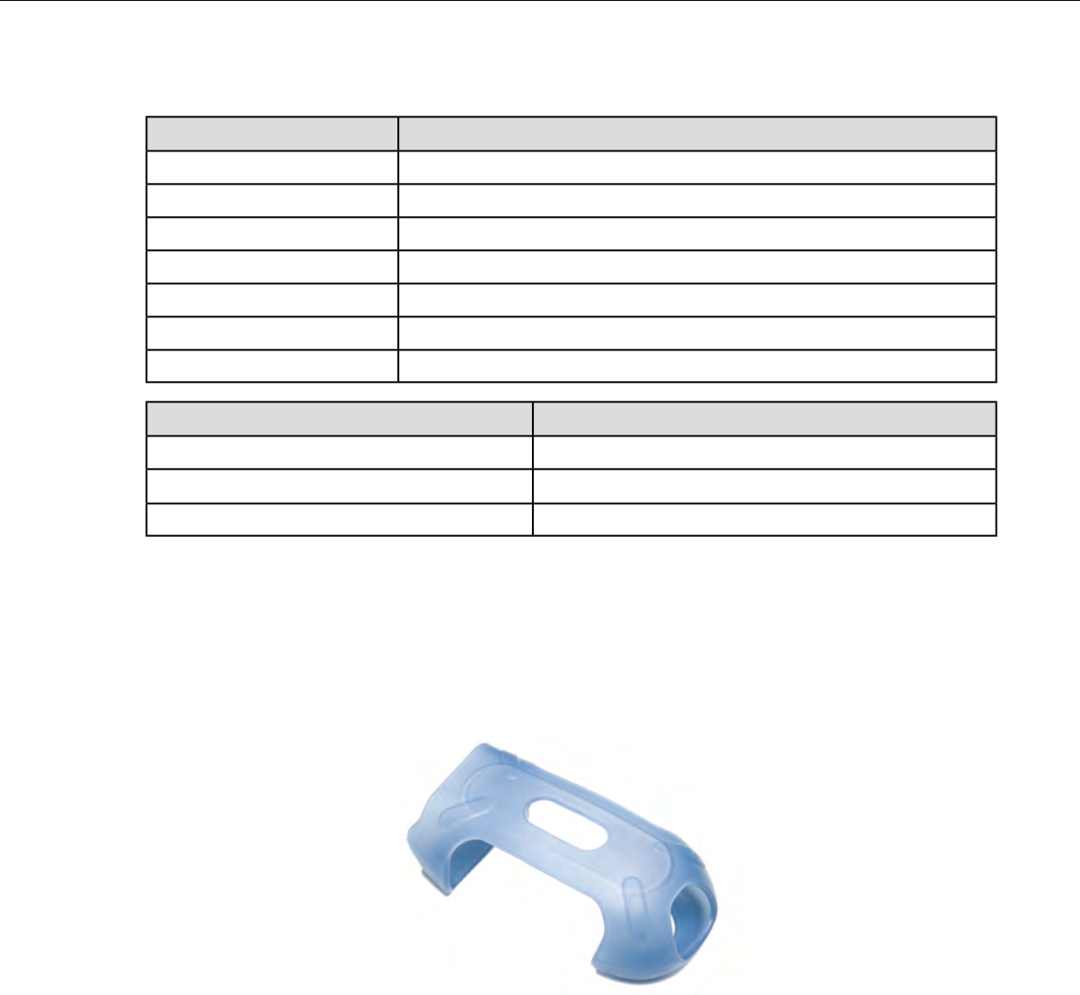
T-Series Belt Specifications
DimensionsBelt Size
18" - 26" (46cm-66cm)XS
24" - 32" (61cm-81cm)S
28" - 36" (71cm-91cm)M
34" - 42" (61cm-107cm)L
40" - 48" (102cm-122cm)XL
46" - 54" (117cm-137cm)XXL
52" - 60" (132cm-152cm)XXXL
SpecificationBelt Part
NylonBelt material
YKK Hook and LoopVelcro®
ITW Nexus 127-3200Belt fastener
Device Covers
Vocollect offers an optional protective covers for its devices.
• The use of a device cover is not required; however, Vocollect strongly recommends using the cover to
help preserve the appearance and prolong the life of the devices.
• Using the protective cover in a freezer environment prolongs battery life.
Figure 65: A500/T5 Elastomer-SKIN Cover
• The device cover does not have to be removed before placing the device into a device charger.
• The EXO Skeleton Cover provides additional drop protection for the device, is easy to remove, and
permits full access to all device features and functions.
Confidential: For informational use by Vocollect Resellers and customers only
Talkman T2 Series | 89
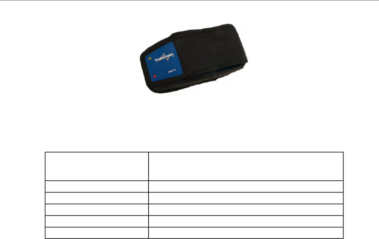
Figure 66: T2-Series Device Cover
• You must remove the device cover before placing the device into a device charger. Failure to do so
could result in damage to both the device and the charger.
T2 Series Device Cover Specifications
Ballistic nylon, 1050-denier black
Fabric
Nylon taffeta, 80-denier black
1/8" thick high-density closed-cell foamFoam
Double polished 0.06Clear Vinyl Sleeve
T-70 nylon, size 69Thread
Used for edge binding bias tapeCordura 1000
Used to hold the cover flap downVelcro®
Putting a Cover on a T2 Series Device
1. If the device is not already off, press and hold the yellow play/pause button until the LED indicator
turns solid red and then off.
2. Disconnect any peripherals.
Confidential: For informational use by Vocollect Resellers and customers only
90 | Vocollect Hardware Documentation
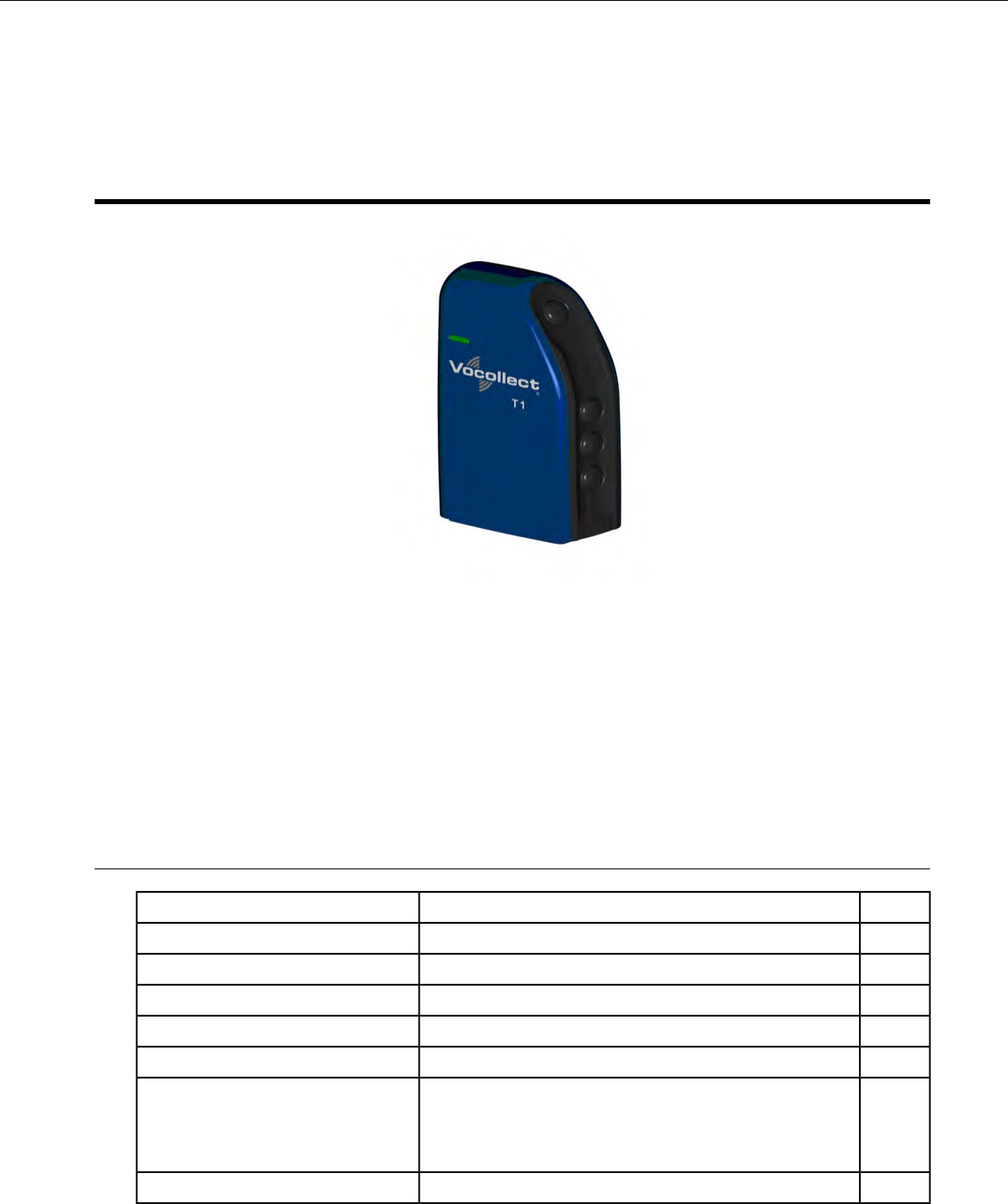
Chapter 6
Talkman T1
Figure 67: Talkman T1
The Talkman®T1 is Vocollect's light industrial voice-enabled device for dry, non-freezer environments.
The device is worn in a holster and is designed to be used only with the Vocollect SL-4 Light Industrial
Behind-the-Head Headset.
This device and headset solution is ideal for less noisy work areas because the SL-4 speaker sits farther
from the head than in Vocollect's SR-Series headsets. As a result, users must set the device volume to
a level appropriate for their environments. The Talkman T1 speech recognition performance, however,
is comparable to the rest of the Talkman line of devices.
T1 Specifications: Talkman T1
5.3 ounces (150 g) (with battery)Weight
100 mmLength
51.5 mmWidth
24 mmDepth
32° to 122° F (0° to 50° C)Operating Temperature
-40° to 158° F (-40° to 70° C)Storage Temperature
The device is not designed to be repeatedly dropped. The
device has been tested to the following specifications:
Drop Tested
• 18 drops from 4 feet
5 to 95% non-condensingHumidity
Confidential: For informational use by Vocollect Resellers and customers only

IP54Enclosure Rating
Charging the T1
The T1 battery is designed to be charged either while still seated in the device or separately in a Vocollect
charger.
Note: A fully depleted T1 battery requires 4.5 to 5 hours to charge.
T1 Batteries Specifications
Electrical Specifications
• Cells: The battery pack uses one lithium ion cell.
• Nominal voltage = 3.7V
• Watt Hours = 7.3WHr
• Protection circuit characteristics: The pack contains a protection circuit that prevents over and under
voltage conditions on the cells and protects the pack from damage as a result of a short circuit between
the positive and negative terminals of the battery.
• The battery pack contains custom electronics for temperature measurement.
• Battery Charging: The battery pack must be charged only in a Vocollect designated charger.
Mechanical and Environmental Specifications
• Drop-test specifications: The battery meets the transient drop criteria.
• Environmental specifications: The battery pack halves are sonically welded together to protect the
internals from water and dust. The battery functions properly in the following conditions:
Operating Temperature: 0°C to 50°C (32°F to 122°F)
Storage Temperature: -40°C to 70°C (-40°F to 158°F)
Humidity: 95% non-condensing
Rain/dust: IP54
Battery Notifications
Battery warnings for a Talkman battery occur at the following levels:
• First warning = 3,550 mV
• Critical warning = 3,350 mV
Charging a T1 Battery in a Device
1. Remove the device from the holster.
2. Disconnect the headset from the device.
3. Insert the device into an open slot on the charger.
4. After the device has been placed into the charger, make sure that the LED indicator on the device
turns on and is green.
a) If the LED does not turn on after 30 seconds, remove the device from the charger slot and then
place it into the slot again.
Confidential: For informational use by Vocollect Resellers and customers only
92 | Vocollect Hardware Documentation

b) If the LED indicator still does not turn on, try another charger slot.
Caution: Do not attempt to place the device into the charger unless you have first disconnected
the headset.
Charging a T1 Battery in a T1 10-Bay Combination Charger
1. Remove the battery from the Talkman device.
2. Hold the battery with its contacts to the top and facing away from you.
3. Place the battery into an open battery slot on the front of the charger.
Charging a T1 Battery with a T1 Single Charger Cable
1. Grasp and squeeze the sides of the I/O connector on the cable.
2. Attach the I/O connector onto the T1's connectors and release the I/O connector. Ensure the flush
side of the I/O connector faces front with the device’s front.
3. Insert the other end of the charging cable into the barrel jack on the plug cable.
4. Plug the charger into an electrical outlet.
Removing a T1 Device From a T1 10-Bay Combination Charger
Note: The device is ready to use when the LED indicator on the device is green. If the LED is amber,
the device is not ready to be used.
Important: If a device displays a solid red light, contact your system administrator.
1. Make sure that the device is ready to use.
2. Pull up on the device to remove it from the device charger.
Disconnecting a T1 Device from a T1 Single Charger Cable
Note: The device is ready to use when the LED indicator on the device is green. If the LED is amber,
the device is not ready to be used.
Important: If a device's LED continuously displays red, contact your system administrator.
1. Unplug the charger from the electrical outlet.
2. Gently remove it from the T1 device by squeezing the sides of the I/O connector on the cable. Do not
pull the cable wire.
Inserting a Battery into a Talkman T1 Device
Make sure the battery to be inserted is fully charged.
1. Hold the Talkman with the battery compartment facing you.
2. Hold the battery with the contacts facing to the bottom and away from you.
3. Place the battery in at an angle, non-contact end first.
4. Push the bottom of the battery into place.
You will hear a click when the battery is in place.
Confidential: For informational use by Vocollect Resellers and customers only
Talkman T1 | 93
Caution: Do not force the battery into the compartment. You may damage the battery or the
device. If the battery does not snap easily into place, reposition the battery in the compartment
and try again.
Make sure the battery is firmly in place and can't be removed without pressing the battery release button.
Removing a Battery from a Talkman T1 Device
Make sure the Talkman device is off.
Caution: Do not remove the battery until the LED indicator is off. If you remove the battery when
the device is on or sleeping, any data collected could be lost.
1. Hold the device in one hand with the battery compartment facing toward you.
2. Push the battery release button up and pull the battery out.
Battery Warm-Up Time
If a battery has been used in a cold environment, it will not begin charging until it warms up sufficiently.
Approximate warm-up timeTemperature of battery use
6 minutes-4°C (24.8°F)
10 minutes-10°C (14.0°F)
22 minutes-20°C (-4°F)
30 minutes-30°C (-22°F)
About LED Indicators
Vocollect Talkman devices, SRX and SRX2 headsets, and their chargers have LEDs that indicate the
state of the equipment. These LEDs may be on, off or blink. In some cases an LED will blink, alternating
between two colors.
If the LEDs indicate that there is a problem, refer to information on troubleshooting to solve the problem.
See also Troubleshooting Problems Indicated by LED.
T1 Device LED Indicators
T1StateLED
Device is on
Also, one of the following:
On
Green
• adjusting volume
• sampling noise
• retraining a word
• changing the active operator
• after speaking:
• "Talkman help"
Confidential: For informational use by Vocollect Resellers and customers only
94 | Vocollect Hardware Documentation

T1StateLED
• "Talkman repeat"
• "Talkman continue"
• "Talkman backup"
The device is in a chargerFast Blink
One of the following:Slow Blink
• the device is in sleep mode and not in a charger
• the voice application selection menu is in use
• certain portions of software are loading
Device is turning on
Device is turning off
On Briefly
Red
Error, contact system administratorOn Continuously
One of the following:Blinking
• retrieving and loading an operator from VoiceConsole
• retrieving, reading and loading a voice application from
VoiceConsole
• certain portions of software are loading
Not chargingOff
Amber/Yellow
ChargingOn
Accessories
Vocollect offers a variety of accessories for wearing, protecting, and facilitating the operations of Talkman
and other handheld devices.
Confidential: For informational use by Vocollect Resellers and customers only
Talkman T1 | 95
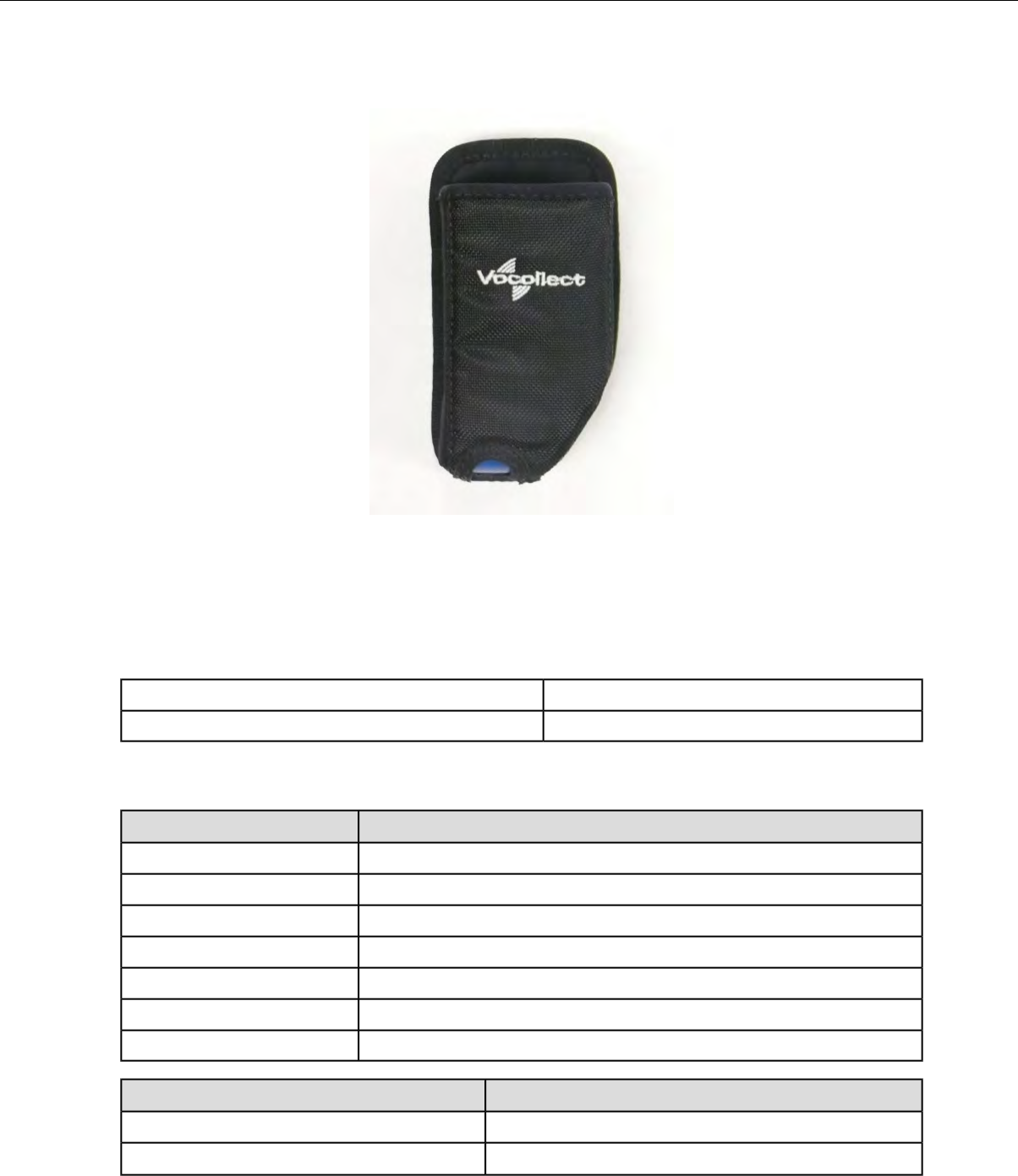
T1 Holster
Figure 68: T1 Holster
Operators should wear the T1 device with a customized holster. An industrial-grade belt may be purchased
from Vocollect or the holster can be clipped to any belt. The holster protects the device from wear and
protects the battery.
T1 Holster Specifications
NylonBelt material
Non-replacableBelt fastener
T-Series Belt Specifications
DimensionsBelt Size
18" - 26" (46cm-66cm)XS
24" - 32" (61cm-81cm)S
28" - 36" (71cm-91cm)M
34" - 42" (61cm-107cm)L
40" - 48" (102cm-122cm)XL
46" - 54" (117cm-137cm)XXL
52" - 60" (132cm-152cm)XXXL
SpecificationBelt Part
NylonBelt material
YKK Hook and LoopVelcro®
Confidential: For informational use by Vocollect Resellers and customers only
96 | Vocollect Hardware Documentation
SpecificationBelt Part
ITW Nexus 127-3200Belt fastener
Using the T1 Holster
1. Make sure the opening on the holster is pointed up.
2. Slide the clip down onto a belt.
3. Insert the T1 device.
4. To remove the device, push the T1 from the bottom of the holster.
Caution: Do not pull the device out of the holster by the headset cable. Damage to the unit may
occur.
Confidential: For informational use by Vocollect Resellers and customers only
Talkman T1 | 97

Chapter 7
Vocollect Wired Headsets
An operator uses a headset with a microphone to interact with a device by hearing and responding to
instructions. Based on the operator's responses, the device transmits data messages back to the host
computer.
Vocollect offers a variety of wired headsets designed for different environments and wearing preferences.
The SR-20 tends to be the most popular general use headset. Other models provide behind-the-head,
light industrial, and hardhat options. Headset features include:
• Bidirectional noise-canceling microphones for optimal noise cancelation.
• Windscreen to reduce breathing and other background noises that can make it hard for the device to
understand what an operator is saying.
• Sealed components to prevent corrosion.
• Dual strap, padded, stainless steel headbands for increased comfort and stability.
• Single strap, lightweight headbands for a personalized fit.
• Single-cup models with single ear cups that pivot vertically and horizontally and can be worn on
either ear.
• Dual-cup model for added noise reduction in loud work environments.
• Foam ear pads for quick and easy replacement.
•A rotating lever on the outside of the earpiece for moving the microphone up and down without causing
stress on the microphone boom.
• Repeatable microphone position; a groove catches the boom, placing it in the proper position when
the boom is swiveled down for operation.
The headsets, microphones, cords, and connectors used with the Vocollect Voice®system are delicate
pieces of electronic equipment. Proper care will ensure that they work well for a long time.
See Care and Use of Headsets and Microphones for more information.
Important: For maximum hygiene, Vocollect discourages sharing headsets among operators. The
design of the SRX2 Wireless Headset features an electronics module that can be removed from the
headband and windscreen. The electronics module can be shared among operators over multiple
shifts, providing some level of hygiene while potentially reducing costs.
SL-4 and SL-14 Vocollect Light Industrial Behind-the-Head Headset
The SL-4 and SL-14 Vocollect®light industrial, behind-the-head headsets are behind-the-head worn
headsets designed for worker in light industrial environments. The design of these headsets is appealing
for workers who can not wear typical over-the-head models due to hair style, headgear or comfort issues.
The SL-4 works with the Talkman T1 devices while the SL-14 works with the Talkman A500, T2- or
T5-series devices.
Note: These lightweight, non-repairable headsets may be damaged if the "Proper Use and Care"
instructions are not followed. See the "Proper Use and Care" document included with the headset
for information.
Confidential: For informational use by Vocollect Resellers and customers only
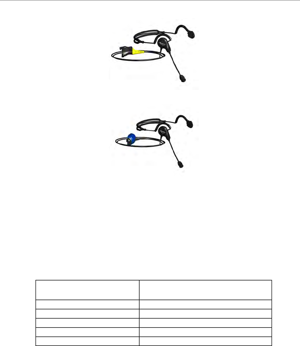
Figure 69: SL-14 Light Industrial Behind-the-Head Headset
Figure 70: SL-4 Light Industrial Behind-the-Head Headset
• The behind-the-head SL headsets are light-industrial headsets designed specifically for speech
recognition. They come with an adjustable headband, giving the user a personalized and comfortable
fit.
• The behind-the-head SL headsets come in both right and left-sided configurations (identify the
configurations desired when ordering).
In addition, the SL-14 and SL-4’s less obtrusive form makes these headsets suitable for environments
where voice-enabled workers are visible to, or interacting with, the public.
• The headset is designed for use in an ambient environment (non-condensing).
• Proper use and care is to secure the cord to clothing with clips provided for both operational safety
as well as to enhance headset stability.
SL-14 Headset Specifications
2.19 ounces (62 g) with cable
1.13 ounces (32 g) without cable
Weight
32°F to 122°F (0°C to 50°C)Operating temperature
-40°F to 158°F (-40°C to 70°C)Storage temperature
5-95% non-condensingHumidity
Meets IP54Enclosure rating
Not applicableNoise Reduction Rating
Confidential: For informational use by Vocollect Resellers and customers only
100 | Vocollect Hardware Documentation
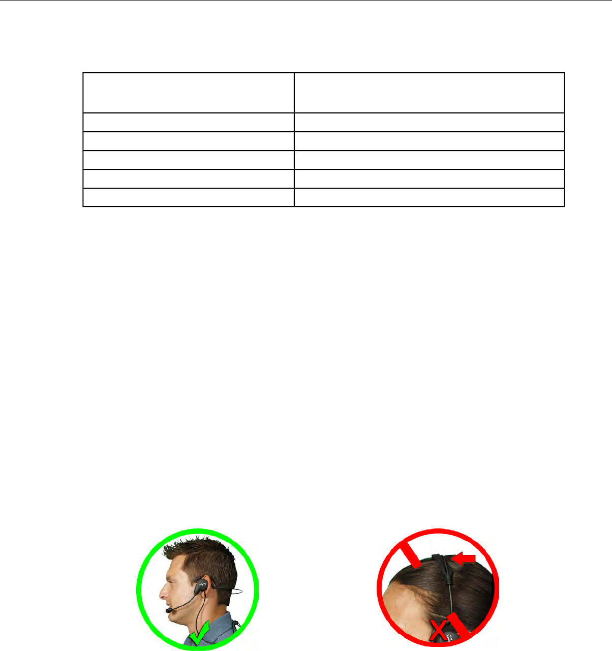
SL-4 Headset Specifications
2.19 ounces (62 g) with cable
1.13 ounces (32 g) without cable
Weight
0°C to 50°C (32°F to 122°F)Operating temperature
-40°C to 70°C (-40°F to 158°F)Storage temperature
5-95% non-condensingHumidity
Meets IP54Enclosure rating
Not applicableNoise Reduction Rating
Wearing the SL-14 or SL-4 Behind-the-Head Headset
1. Adjust the headset's adjustable headband so it will fit snugly on your head.
2. Place the headset behind your head, and slip the ear loops over your ears.
3. Place the microphone at the corner of your mouth; it should be positioned about 1/4" away from your
face.
The flat side of the microphone will face your mouth when the microphone is positioned properly.
4. Clip the headset cord to the collar or top of your shirt or jacket where it can comfortably fall down
your back. This keeps the cord away from your chest and arms where it can become tangled with
your work.
5. Let the cable fall down your back, and clip it to the belt near the device.
6. Connect the headset to the device.
Proper Use and Care Instructions for Talkman T1 and SL-4/SL-14 Headsets
The equipment you have purchased has been carefully inspected at the factory. It is not designed to withstand
abuse, including use in condensing, wet or freezing conditions. The instructions below are designed to ensure
the equipment continues to function in accordance with the published specifications. Damage may be caused
to the equipment when used or maintained in an improper manner. Vocollect will not honor repair or
replacement requests for damages caused by improper use, maintenance, negligence or abuse, including, but
not limited to, those specifically identified below. In these cases, a replacement headset purchase is required,
regardless of the age or warranty status of the original equipment.
Confidential: For informational use by Vocollect Resellers and customers only
Vocollect Wired Headsets | 101
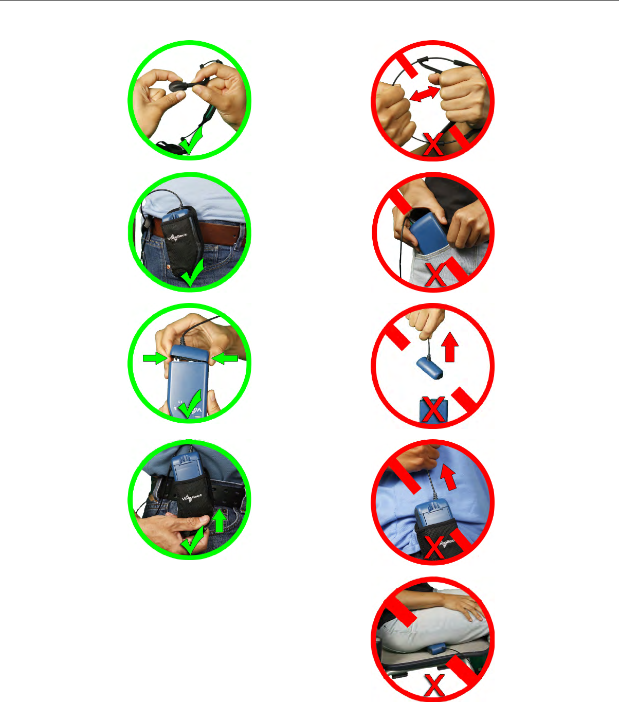
Confidential: For informational use by Vocollect Resellers and customers only
102 | Vocollect Hardware Documentation
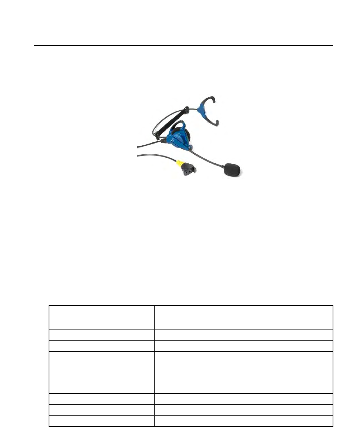
SR-10 and SR-15 Vocollect Behind-the-Head Headset
The SR-15 Vocollect®behind-the-head headset is designed for workers who cannot wear typical
over-the-head headset models due to hair style, headwear, or comfort issues with Talkman A500, T2
and T5-series devices.
The SR-10 Vocollect®behind-the-head headset is a legacy headset formerly used with the Talkman A500,
T2-Series, and T5-Series devices. It is now an end-of-life product but still under support.
Figure 71: SR-15 Behind-the-Head Headset
• The behind-the-head headset is a rugged headset designed specifically for speech recognition in
industrial and warehouse settings. It comes with an adjustable headband, giving the user a
personalized and comfortable fit.
• The behind-the-head headset comes in a single configuration that can be adjusted by the user to be
in a right-ear or left-ear orientation.
• The headset is designed for use in an ambient environment (non-condensing).
• The symmetrically designed ear loop can be worn on either ear.
• Vocollect strongly recommends securing the cord to clothing with clips provided for both operational
safety as well as to enhance headset stability.
• If the cord can not be easily secured, Vocollect recommends that it be clipped near the center of the
headband to evenly distribute any weight caused by a loose cord.
SR-15 Headset Specifications
3.4 ounces (96 g) with cable
2.0 ounces (58 g) without cable
Weight
-40°F to 122°F (-40° to 50°C)Operating temperature
-40°F to 158°F (-40° to 70°C)Storage temperature
Drop Tested • 15 drops from 7 feet (2.1 m) at minimum and maximum
operating temperatures
• 50 drops from 6 feet (1.8 m) at minimum and maximum
operating temperatures
Meets IP31Enclosure rating
5-90% condensingHumidity
Not applicableNoise Reduction Rating
Confidential: For informational use by Vocollect Resellers and customers only
Vocollect Wired Headsets | 103
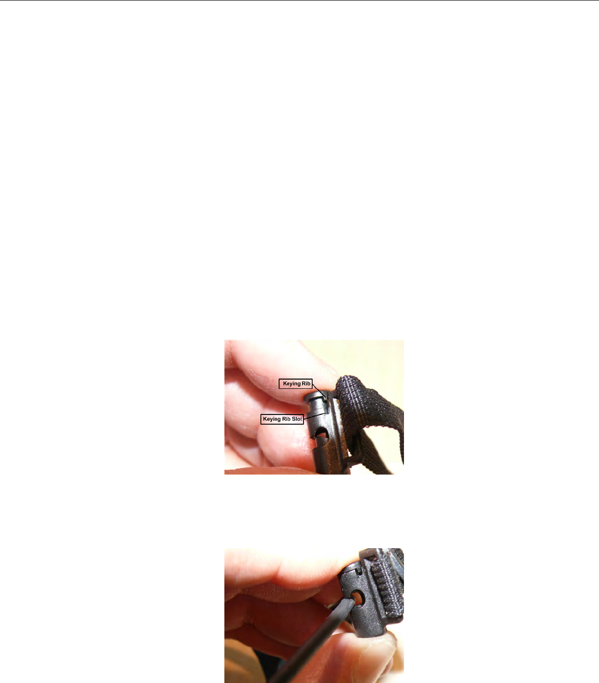
Wearing the SR-15 Behind-the-Head Headset
1. Loosen the cable at the headband cord clip on the back of the headband to allow enough slack to move
the speaker away from the earloop.
2. Adjust the nylon band on the adjustment strap so that it lies flat against the headband of the headset.
3. Grasp the headset's ear loops and spread them slightly apart.
4. Place the headset behind your head, and slip the ear loops over your ears.
5. Adjust the headset's speaker so it fits snugly over your ear.
6. Place the microphone at the corner of your mouth; it should be positioned about 1/4" away from your
face.
Blue waves on the microphone face your mouth when the microphone is positioned properly.
7. Clip the headset cord to your shirt or jacket where it is comfortable.
8. Let the cable fall down your back, and clip it to the belt near the device. If you are using a device
cover, we recommend that you clip the bottom clip directly onto the cover.
9. Adjust the nylon adjustment strap on the back of the headband so that it fits firmly, but comfortably,
against the back of your head. The nylon band can be adjusted by sliding the plastic buckle.
10. Connect the headset to the device.
Removing the SR-15 Headset Adjustment Strap
1. Align the keying rib on the plunger with the slot in the barrel.
Figure 72: Keying Rib and Slot
2. Push the plunger all the way down until the plunger top lip contacts the top of the barrel, making
sure the keying rib is inside the keying rib slot.
3. With the plunger pressed all the way in, pull the adjustment strap clip to remove it from the headband.
Figure 73: Removing the Adjustment Strap
Confidential: For informational use by Vocollect Resellers and customers only
104 | Vocollect Hardware Documentation

4. Repeat these steps for the clip on the other side.
Attaching the SR-15 Headset Adjustment Strap
1. Align the keying rib on the plunger with the slot in the barrel.
2. Push the plunger all the way down until the plunger top lip contacts the top of the barrel, making
sure the keying rib is inside the keying rib slot.
3. With the plunger pressed all the way in, place the headband into the slot on the side of the adjustment
strap barrel.
4. Repeat these steps for the clip on the other side.
Replacing the Ear Pad on the SR-15 Headset
1. With headset removed and disconnected, rotate the headband away from the microphone/speaker
assembly.
• If the cable is clipped to the center of the back of the headset, either unclip it or allow enough slack
to be able to move the headband away from the microphone/speaker assembly.
2. Remove the worn foam cover from the speaker assembly.
3. Place the new foam cover over one of the three mounting ribs.
4. Gently pull the foam over the other two mounting ribs.
5. Rotate the microphone/speaker assembly back towards the headband.
You will hear a click when it is in place.
SR-20-Series Vocollect Lightweight Headset
Figure 74: The SR-20 Lightweight Headset
The SR-20 Vocollect®Lightweight Headset is able to withstand heavy use in challenging warehouse
conditions, such as extreme temperature differences, condensation and accidental drops. The SR-20
Headset also remains comfortable during a full shift.
The SR-21 Headset is a universal version designed to be used with handheld devices.
SR-20 Headset Specifications
SR-20 with straight cord
Confidential: For informational use by Vocollect Resellers and customers only
Vocollect Wired Headsets | 105

5.4 ounces (153 g) with cable
3.9 ounces (110 g) without cable
Weight
-40°F to 122°F (-40° to 50°C)Operating temperature
-40°F to 158°F (-40° to 70°C)Storage temperature
Drop Tested • 15 drops from 7 feet (2.1 m) at minimum and maximum
operating temperatures
• 50 drops from 6 feet (1.8 m) at minimum and maximum
operating temperatures
Meets IP67Enclosure rating
5-95% condensingHumidity
Not applicableNoise Reduction Rating
SR-20 with coiled cord
6.5 ounces (184 g) with cable
3.9 ounces (110 g) without cable
Weight
-40°F to 122°F (-40° to 50°C)Operating temperature
-40°F to 158°F (-40° to 70°C)Storage temperature
Meets IP67Enclosure rating
100% condensingHumidity
Not applicableNoise Reduction Rating
SR-21 Headset Specifications
5.0 ounces (141 g) with cable
3.9 ounces (110 g) without cable
Weight
-40°F to 122°F (-40° to 50°C)Operating temperature
-40°F to 158°F (-40° to 70°C)Storage temperature
Meets IP67Enclosure rating
100% condensingHumidity
Not applicableNoise Reduction Rating
Replacing the Ear Pad on the SR-20 Series Headsets
1. With headset removed and disconnected, rotate the microphone boom so that it is in line with the
headset yoke.
2. Hold the headset by the yoke in one hand. With the other hand rotate the earpiece counter-clockwise
10°.
3. Disengage the earpiece section from the headset.
4. Remove the worn foam cover.
5. With the black O-ring gasket facing out, place a new ear pad over the ear pad mounting disk.
Confidential: For informational use by Vocollect Resellers and customers only
106 | Vocollect Hardware Documentation

If the ear pad mounting disk does not have a black O-ring gasket attached to it, performance may be
affected. You must replace the entire ear pad mounting disk, which includes the black O-ring gasket.
6. Line up the keys on the earpiece to the headset, connect the mounting disk.
7. Rotate the earpiece clockwise 10° to secure it. Note that the earpiece will not engage with the headset
if it is backwards.
SR-30 Vocollect High-Noise Headset
Figure 75: SR-30 Vocollect®High Noise Headset
The SR-31 Headset is a universal version designed to be used with handheld devices.
SR-30 Headset Specifications
7.7 ounces (218 g) with cable
6.2 ounces (175 g) without cable
Weight
-40°F to 122°F (-40° to 50°C)Operating temperature
-40°F to 158°F (-40° to 70°C)Storage temperature
Drop Tested • 15 drops from 7 feet (2.1 m) at minimum and maximum
operating temperatures
• 50 drops from 6 feet (1.8 m) at minimum and maximum
operating temperatures
Meets IP67Enclosure rating
5-90% condensingHumidity
Average 5 dBNoise Reduction Rating
SR-31 Headset Specifications
7.3 ounces (206 g) with cable
6.2 ounces (175 g) without cable
Weight
Confidential: For informational use by Vocollect Resellers and customers only
Vocollect Wired Headsets | 107
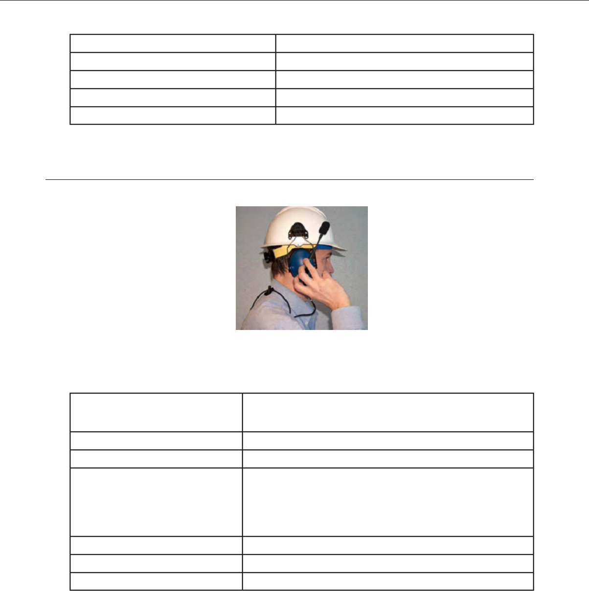
-40°F to 122°F (-40° to 50°C)Operating temperature
-40°F to 158°F (-40° to 70°C)Storage temperature
Meets IP67Enclosure rating
100% condensingHumidity
Average 6 dBNoise Reduction Rating
SR-35 Vocollect Hard-Hat Headset
The SR-35 Vocollect®hard-hat headset has a built-in clip that fits most industrial hard hats.
Figure 76: SR-35 Hard Hat Headset
SR-35 Headset Specifications
6.2 ounces (175 g) with cable
4.7 ounces (133 g) without cable
Weight
-40°F to 122°F (-40° to 50°C)Operating temperature
-40°F to 158°F (-40° to 70°C)Storage temperature
Drop Tested • 15 drops from 7 feet (2.1 m) at minimum and maximum
operating temperatures
• 50 drops from 6 feet (1.8 m) at minimum and maximum
operating temperatures
Meets IP67Enclosure rating
5-90% condensingHumidity
Average 5 dBNoise Reduction Rating
Confidential: For informational use by Vocollect Resellers and customers only
108 | Vocollect Hardware Documentation
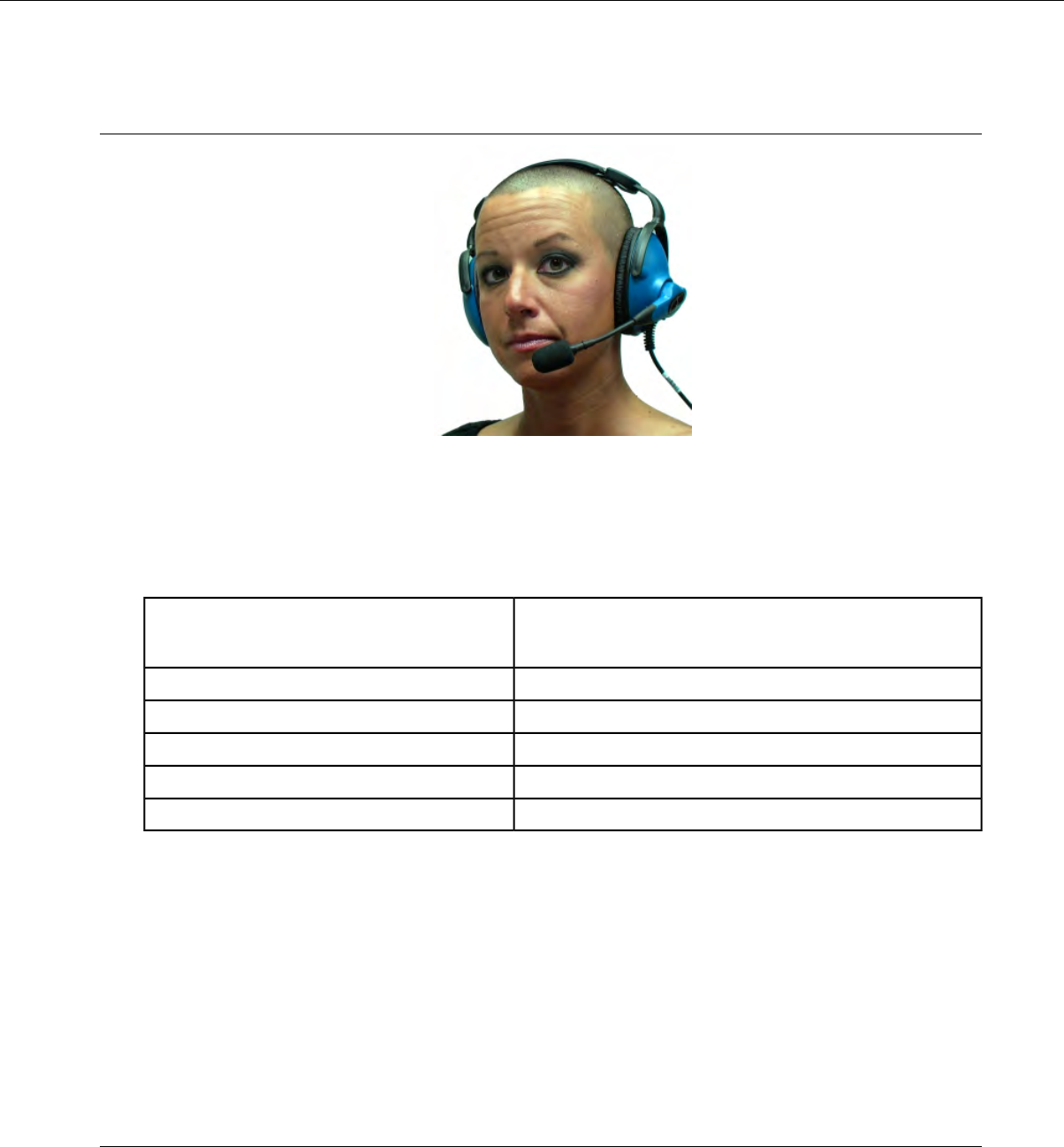
SR-40 Vocollect Dual-Cup Headset
Figure 77: SR-40 Dual-Cup Headset
The SR-40 Vocollect®Dual-Cup headset is designed for extremely loud work environments. The two ear
cups block out intrusive noise.
SR-40 Headset Specifications
9.6 ounces (272 g) with cable
8.1 ounces (229 g) without cable
Weight
-40°F to 122°F (-40°C to 50°C)Operating temperature
-40°F to 158°F (-40°C to 70°C)Storage temperature
Meets IP67Enclosure rating
100% condensingHumidity
Average 7 dbNoise Reduction Rating
Replacing the Ear Pad on the SR-30, SR-35 and the SR-40 Headsets
1. With headset removed and disconnected, hold the headset in one hand.
2. At the seam on the bottom of the ear cup housing where the ear pad connects to the plastic ear cup,
pull the ear pad and plastic mounting plate outward until it disconnects.
3. Remove the worn ear pad from the plastic mounting plate and place the new ear pad over the plastic
mounting plate. Do not cover the three posts.
4. Line up the posts on the plastic mounting plate with the ear cup housing and snap into place.
Care and Use of Headsets and Microphones
The headsets and microphones used with the Vocollect Voice system are delicate pieces of electronic
equipment. Proper care and use of these products will ensure that they work well for a long time.
Confidential: For informational use by Vocollect Resellers and customers only
Vocollect Wired Headsets | 109

Important: For maximum hygiene, Vocollect discourages sharing headsets among operators.
The design of the SRX2 Wireless Headset features an electronics module that can be removed from
the headband and windscreen. The electronics module can be shared among operators over multiple
shifts, providing some level of hygiene while potentially reducing costs.
Wearing Headsets: General Procedures
This describes the standard procedures for wearing Vocollect headsets. Note that special types of headsets
have somewhat different procedures.
Tip:
Always use pads and windscreens with Vocollect headsets to protect the equipment and ensure
optimum speech recognition performance.
1. Put the headset on and adjust the ear pad to fit snugly over your ear.
•For the Hard-Hat Headset, first insert the headset bracket into the left or right slot on the hardhat,
then put on the hardhat.
2. Swing the microphone into position with the rotating lever at the earpiece.
Important: Do not swivel the microphone boom by the flexible end. Use the rotating lever on
the outside of the earpiece.
3. Make final adjustments with the flexible boom so that the microphone is positioned at the corner of
your mouth.
A dot or the word "talk" on the microphone faces your mouth when the microphone is positioned
properly.
Make sure that there is a windscreen on the microphone. A windscreen improves performance.
4. Clip the headset wire to collar and belt. Let the wire fall down your back, and clip it to the belt near
the device.
If you use a device cover, Vocollect recommends that you clip the bottom clip directly onto the cover.
5. Connect or pair the headset to the device.
Adjusting Headsets for Comfort
Vocollect has designed the SR Series headsets based on data for most head shapes and sizes. Because
the headset is the most personal piece of voice equipment and must remain stable while workers perform
very physical tasks, users may benefit from these headset adjustment guidelines.
•Placement of the "T-bar" pad: The SR-20, SR-21, SR-30, and SRX models have pads called "t-bars"
opposite the speaker side of the headset. The t-bar should be positioned on a part of the head with
the least amount of muscle.
As an operator speaks, the muscle above the ear flexes. If the t-bar is placed on this muscle, the
headset applies pressure to the artery and nerves beneath it and can cause the operator some
discomfort. The operator can locate this muscle by moving his or her jaw and feeling the area above
the ear for movement. Some operators choose to alternate the headset position on either side of their
heads during their shifts.
Confidential: For informational use by Vocollect Resellers and customers only
110 | Vocollect Hardware Documentation
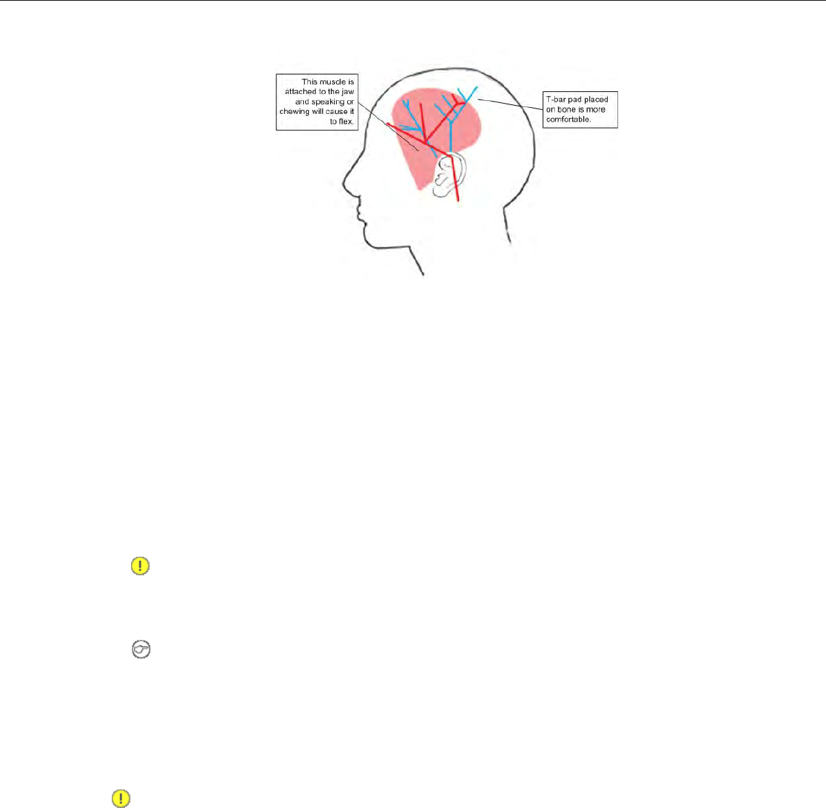
Figure 78: T-bar Pad Placement on the Head
•Headset pad options: Vocollect offers a variety of pads to meet the unique requirements of workers
and working conditions.
Standard foam pads: provide cushioning and soft surfaces wherever the headset comes in contact
with the operator. Available on all headsets.
Leatherette ear pads: have a faux leather exterior that is a more firm and supportive and more
moisture resistant than standard foam pads. Offered for all SR-20 through SR-40 models.
Memory foam pads: offer superior cushioning support and comfort. Available in earpads for the
SR-20/21 and in t-bar pads for the SR-20/21 and SR-30.
Removing Headsets
1. Disconnect the headset from the device.
Important: Do not pull on the headset's cord.
2. Unclip the headset cord from your shirt or jacket.
3. Carefully remove the headset from your head.
Note: For the Hard-Hat Headset, remove the hard hat. Press the release clip to remove the
headset unit from the hardhat bracket.
Cleaning Windscreens
Vocollect recommends that you change windscreens every 90 days for optimum speech recognition
performance.
Important: Soap, cleaning solutions, and vigorous washing will remove the protective coating on
the windscreen and decrease its effectiveness.
1. Remove the windscreen from the microphone.
2. Rinse the windscreen under warm water.
3. Squeeze out the excess water and let it air dry thoroughly.
Confidential: For informational use by Vocollect Resellers and customers only
Vocollect Wired Headsets | 111

Cleaning Headsets
Note: Commercial cleaning solvents are not recommended.
• Clean the plastic parts of the headsets with a soft cloth dampened with water. To clean and disinfect
the headset plastic, use a pre-moistened alcohol wipe.
•If the Talkman Connectors or plugs become contaminated, use a pre-moistened alcohol wipe to remove
dirt or residue.
•If the metal connection points on the Talkman's Connectors become discolored, use a soft pencil eraser
to clean them.
• Do not use unapproved liquids to clean the yellow, blue, and red Talkman Connectors (TCOs) and
any associated headset, scanner, or device plugs.
Cleaning the Headband Pad
Note: Vocollect strongly recommends that you leave the headband pad in place when cleaning it.
If you must remove the entire pad to clean it, use care to line up the headband pad with the topmost
part of the headband when you place it back on the headband.
• Leave the headband in place and simply wipe the headband with a soft cloth. If necessary, use a
pre-moistened alcohol wipe to clean and disinfect the unit.
Cleaning the Dual-Cupped Headset Ear Pad Cover
• The cupped headset ear pad cover is made of 100% cotton flannel and may shrink if washed and dried
in a dryer. Vocollect recommends that the covers be hand or machine washed in cold or warm water
and then air dried.
Confidential: For informational use by Vocollect Resellers and customers only
112 | Vocollect Hardware Documentation

Chapter 8
Vocollect Wireless Headsets
An operator uses a headset with a microphone to interact with a device by hearing and responding to
instructions. Based on the operator's responses, the device transmits data messages back to the host
computer.
The Vocollect ®SRX and SRX2 speech-recognition headsets feature industrial grade use of Bluetooth
Wireless Technology. These wireless headsets manage the quality of voice input/output, have no cables
to connect, and remain connected to a device up to ten meters away.
Vocollect SRX and SRX2 wireless headset features include:
• Bidirectional noise canceling microphones for optimal noise cancellation.
• Windscreen to reduce breathing and other background noises that can make it hard for the device to
understand what an operator is saying.
• Sealed components to prevent corrosion.
• Padded, lightweight headbands for increased comfort and personalized fit.
• Single ear cups that pivot vertically and horizontally and can be worn on either ear.
• Foam ear pads for quick and easy replacement.
•A rotating lever on the outside of the earpiece for moving the microphone up and down without causing
stress on the microphone boom.
• Repeatable microphone position; a groove catches the boom, placing it in the proper position when
the boom is swiveled down for operation.
The headsets and microphones used with the Vocollect Voice®system are delicate pieces of electronic
equipment. Proper care will ensure that they work well for a long time.
See Care and Use of Headsets and Microphones for more information.
The Bluetooth word mark and logos are owned by the Bluetooth SIG, Inc.
and any use of such marks by Vocollect is under license. Other trademarks
and trade names are those of their respective owners.
Confidential: For informational use by Vocollect Resellers and customers only
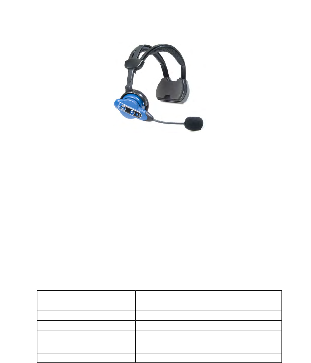
Vocollect SRX Wireless Headset
Figure 79: SRX Wireless Headset
The Vocollect ®SRX speech-recognition headset features industrial grade use of Bluetooth Wireless
Technology. The SRX headset manages the quality of voice input/output in the headset itself, has no
cables to connect, and remains connected to a device at up to 10 meters away.
• Pairing modes on the headset can only be entered from the powered off state.
• It is best to pair in an area where you are at least three feet away from another Bluetooth device.
This helps ensure your headset does not accidentally pair with the wrong device.
• The SRX remembers its last pairing and will reconnect only with that device. It will not respond to
paging or inquiries from other devices until it is placed in pairing mode again.
• When it is not paired with a device, the SRX headset volume can only be adjusted using the buttons
on the headset.
• When the SRX headset is paired with a device, volume can be adjusted by pressing the Plus and
Minus buttons on the headset or device.
•The SRX headset remembers its last volume setting when powered off and back on, and across battery
removals and replacements.The last volume setting used while paired with a wearable computer is
saved with the operator's profile. This volume level will be restored to the SRX headset upon
reconnection. However, the headset volume may be different upon reconnection if the volume was
changed while it was not connected to a device, or if a different operator used the headset.
A padded Velcro®mobility strap fits across the back of the user's head to provide extra stability.
SRX Wireless Headset Specifications
7.5 ounces (215 g) with battery
5.3 ounces (155g) without battery
Weight
32°F to 104°F (0°C to 40°C)Operating temperature
-40°F to 122°F (-40° to 50°C)Storage temperature
Drop Tested • 25 drops from 6 feet (1.8 m) at minimum and maximum
operating temperatures
Meets IP54Enclosure rating
Confidential: For informational use by Vocollect Resellers and customers only
114 | Vocollect Hardware Documentation
5-95% non-condensingHumidity
Not applicableNoise Reduction Rating
Charging the SRX Headset
Figure 80: SRX Wireless Headset High-Performance Battery
A fully depleted SRX Wireless Headset battery will be fully recharged in less than 4 hours.
A fully charged SRX Wireless Headset battery has 3.7 volts. When the charge depletes to 3.3 volts, the
user will hear a spoken warning, "Headset battery is getting low. Change headset battery now." and the
warning will also be displayed in debug.
SRX Battery Specifications
Electrical Specifications
• Cells: The high capacity battery pack uses two lithium ion cells.
• Nominal voltage = 3.7V
• Watt Hours = 7WHr
• Protection circuit characteristics: The pack contains a protection circuit that prevents over and under
voltage conditions on the cells and protects the pack from damage as a result of a short circuit between
the positive and negative terminals of the battery.
• The battery pack contains custom electronics that provide performance, temperature, and pack
identification to the device. This information is made available to voice management software.
• Battery Charging: The battery pack must be charged only in a Vocollect designated charger.
Charging SRX Wireless Headset Batteries
Important: Once an SRX battery is placed in the charger, it must remain in the charger for a
minimum of five seconds. This allows the charger sufficient time to analyze the state of the battery.
Removing the battery during this five second interval may cause the LED indicator on the charger
to display an incorrect battery status.
Important: Do not force the battery into the compartment. Doing so may result in damage to the
battery or the headset. If the battery does not snap easily into place, reposition the battery in the
compartment and try again.
Note:
• A battery is fully charged and can be removed from the charger when the left and right LED
indicators for that slot on the charger are green.
Confidential: For informational use by Vocollect Resellers and customers only
Vocollect Wireless Headsets | 115

• If you insert a fully charged battery into a charger, the charger will analyze the battery's status
and then "top off" the battery's charge. During this process, the left LED indicator for that slot
on the charger is red. It may take several minutes for this process to complete, at which time
both LED indicators for that slot turn green.
1. Make sure the battery charger is powered. The green LED indicator on the end of the battery charger
should be lit.
2. Power off the headset by pressing and holding the Plus and Minus buttons on the earpiece for three
seconds and then remove the battery.
3. Hold the battery with its contacts to the bottom and the Vocollect logo facing toward you, and insert
it into an empty slot on the battery charger.
4. Press down on the battery until it snaps into place.
5. Make sure the battery is firmly in place and cannot be removed without pressing the battery release
button.
Inserting a Battery into the SRX Wireless Headset
Important: Do not force the battery into the compartment. Doing so may result in damage to the
battery or the headset. If the battery does not snap easily into place, reposition the battery in the
compartment and try again.
1. Make sure the battery is charged. A battery is fully charged and can be removed from the charger
when the left and right LED indicators for that slot on the charger are green.
2. Hold the headset with the battery compartment facing toward you.
3. Place the end of the battery with the contacts into the compartment first so that the contacts on the
bottom of the battery line up with the contacts in the compartment.
4. Press down on the battery until it snaps into place.
5. Make sure the battery is firmly in place and cannot be removed without pressing the battery release
button.
Removing a Battery from an SRX Wireless Headset
Important: Do not remove the battery until the LED indicator on the headset is off.
1. Power off the headset by pressing and holding the Plus and Minus buttons on the earpiece for three
seconds.
2. Hold the headset with the battery compartment facing toward you.
3. Pull the battery release button, located on the left side of the battery compartment, away from the
battery until the end of the battery pops up from the compartment.
4. Lift the battery out of the compartment.
Battery Warm-Up Time
If a battery has been used in a cold environment, it will not begin charging until it warms up sufficiently.
Approximate warm-up timeTemperature of battery use
6 minutes-4°C (24.8°F)
10 minutes-10°C (14.0°F)
22 minutes-20°C (-4°F)
30 minutes-30°C (-22°F)
Confidential: For informational use by Vocollect Resellers and customers only
116 | Vocollect Hardware Documentation
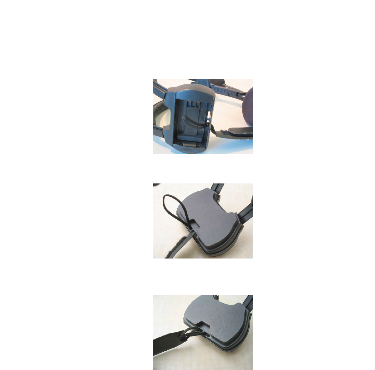
Installing the SRX Mobility Strap
1. Remove the battery from the SRX Wireless Headset.
2. Feed the lanyard end of the mobility strap through one of the eyelets in the headset's battery
compartment. You may find it helpful to push the lanyard through with the tip of a screwdriver. Be
sure to feed the lanyard in the direction shown in the image.
Figure 81: Feeding the Lanyard Through an Eyelet
3. Feed the lanyard back through the other eyelet in the battery compartment.
Figure 82: Feeding the Lanyard Back Through
4. Create a secure loop by inserting the end of the mobility strap with the clip through the lanyard's
loop and pulling it tight.
Figure 83: Inserting the Mobility Strap
5. Clip the other end of the mobility strap to the molded plastic loop on the headset.
Confidential: For informational use by Vocollect Resellers and customers only
Vocollect Wireless Headsets | 117
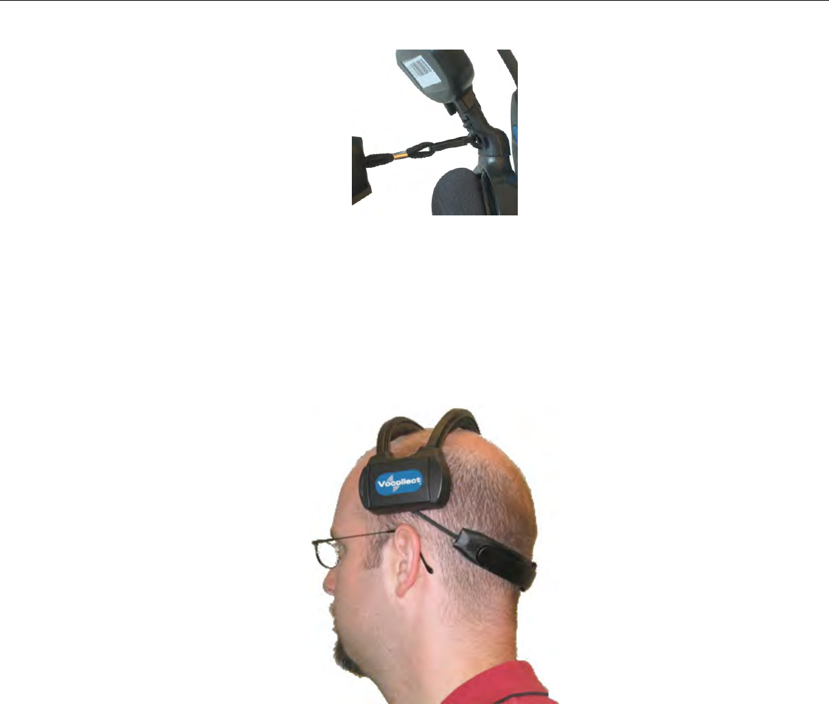
Figure 84: Clipping the Strap to the Loop
Wearing an SRX Wireless Headset
Make sure the Velcro mobility strap is installed on the headset.
1. Put the headset on and adjust the ear pad to fit snugly over your ear.
2. Position the battery compartment directly above, and as closely as possible to, your other ear.
3. Adjust the mobility strap so it fits securely across the back of your head.
Figure 85: Mobility Strap Worn Properly
4. Swing the microphone into position with the rotating lever at the earpiece.
Confidential: For informational use by Vocollect Resellers and customers only
118 | Vocollect Hardware Documentation
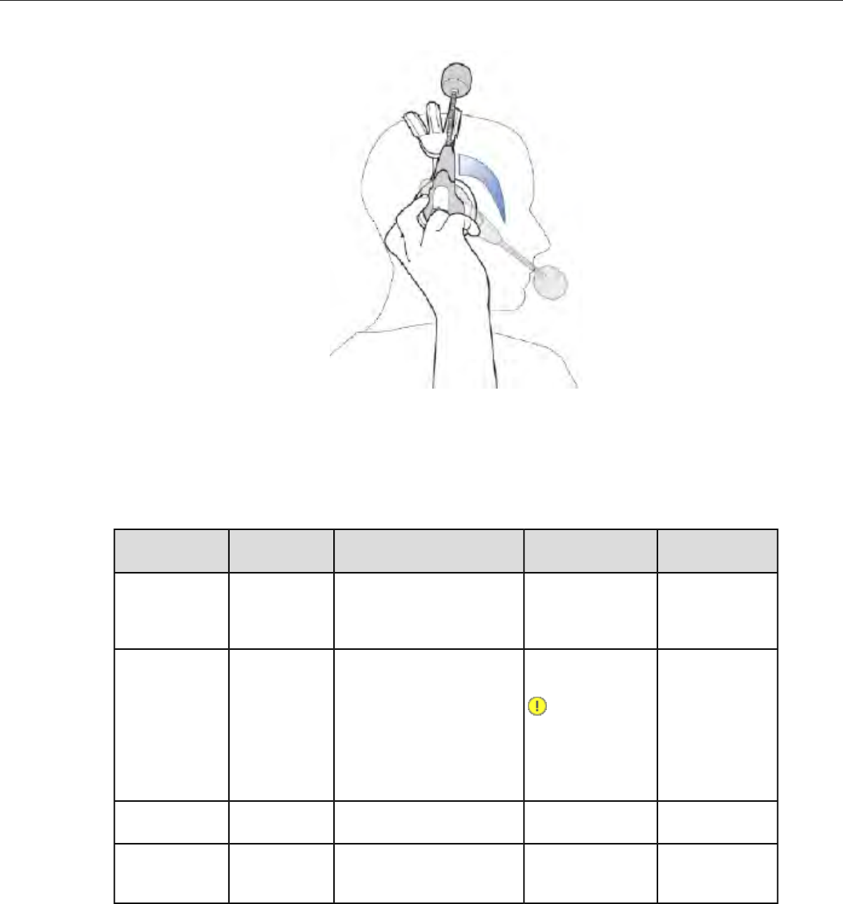
Figure 86: Moving the Microphone Into Position
5. Make final adjustments with the flexible boom so that the microphone is positioned at the corner of
your mouth, about 1/4" away from your face.
Headset Functions and LED Patterns for SRX
ToneLED PatternHeadset ModeUser ActionHeadset
Function
Two high-pitched
tones
Quick flutterHeadset powers on and
searches for the
previously-connected device.
No new pairing takes place.
Hold the Plus
(+) and Minus
(-) buttons for
one second
Power On
Two low-pitched
tones
Solid blue, then
turns off.
Headset is powered off and
cannot be used to perform
work
Hold Plus (+)
and Minus (-)
buttons for
three seconds
Power Off
Important:
Do not remove
when headset
is powered on the battery
until the LED
is off.
Current audio
gets louder
N/AN/APress the Plus
(+) button
Increase volume
Current audio
gets softer
N/AN/APress the
Minus (-)
button
Decrease volume
Confidential: For informational use by Vocollect Resellers and customers only
Vocollect Wireless Headsets | 119
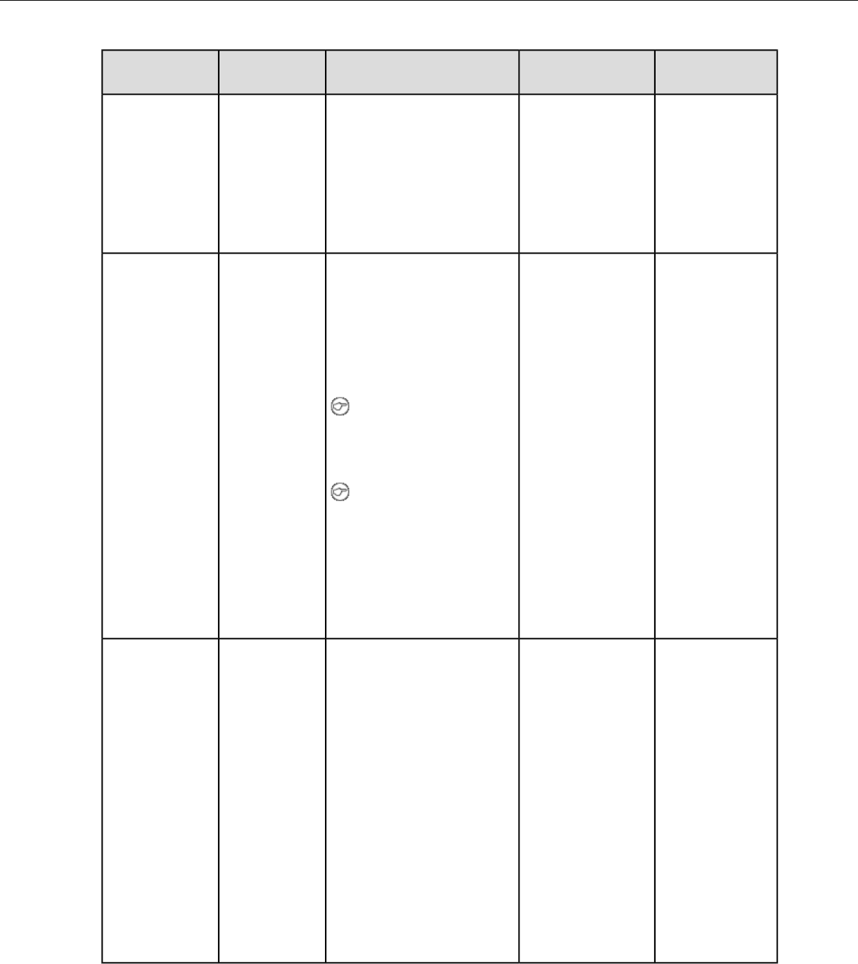
ToneLED PatternHeadset ModeUser ActionHeadset
Function
No tone when
entering mode.
Constant quick
flash: four flashes
Headset disconnects current
pairing and enters low power
pairing mode
Headset attempts to pair
with the nearest un-paired
Hold the Plus
(+) and Minus
(-) buttons for
four seconds
Force disconnect
for manual
pairing in low
power mode
Three ascending
tones upon
pairing with a
device
per second (50 ms
on, 200 ms off)
Bluetooth device. Previous
pairing erased from
headset's memory.
No tone when
entering mode.
Constant flash in
which LED stays lit
Headset enters high power
pairing mode
Headset attempts to pair
with the nearest un-paired
With headset
in pairing
mode, hold the
Plus (+) and
Minus (-)
Switch to high
power pairing
when pairing in
low power mode
has failed
Three ascending
tones upon
pairing with a
device
longer: about two
flashes per second
(350 ms on, 50 ms
off)
Bluetooth device. Previous
pairing erased from
headset's memory.
buttons for
seven seconds
Note: This mode is
recommended when
pairing an SRX headset
with a handheld device
Note: Vocollect does not
recommend this pairing
mode for Talkman
devices. This mode
greatly increases the
likelihood that your
headset will pair with
the wrong device.
Three descending
tones when the
Repeating pattern
of three quick
The headset cannot find an
un-paired Bluetooth device
within range.
N/ALost connection:
• A
previously-paired connection to the
master device is
dropped
flashes, then off for
about a second.
Headset remains in this
mode for 10 minutes while it
device is not
detected by
the headset
at power on waits for a previously-paired
device to come within range.
• A paired
device is
powered off
After 10 minutes of no
activity, the headset powers
off.
•Low Power or
High Power
Pairing
modes fail to
pair with a
device within
60 seconds
Confidential: For informational use by Vocollect Resellers and customers only
120 | Vocollect Hardware Documentation
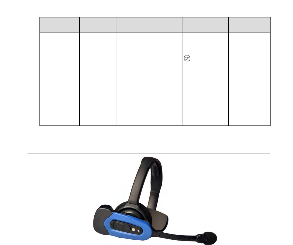
ToneLED PatternHeadset ModeUser ActionHeadset
Function
No tone.
Voice prompt:
"Headset battery
Constant very quick
flutter (about 10
flashes per second).
Headset automatically
enters this mode when the
battery's remaining charge
reaches a minimum
threshold.
N/ALow Battery
is getting low," or
"Headset battery
Note: When
the LED is
is getting low.
blinking in Low
Change headset
battery now."
Battery mode,
no other LED
pattern is
displayed
unless both
buttons are
held to power
off the headset.
Vocollect SRX2 Wireless Headset
Figure 87: SRX2 Wireless Headset
The Vocollect SRX2 Wireless Headset is the second generation wireless headset from Vocollect that has
been designed to provide better recognition accuracy, work across all environments and create a more
comfortable experience for the users.
When used with Vocollect VoiceCatalyst software, the SRX2 headset with Vocollect SoundSense™
Technology provides significant voice recognition benefits. This technology can increase speed and
accuracy, especially in noisy or fast-paced environments.
The highlights of the product are:
•Better recognition with Vocollect SoundSense™Technology (50% reduced insertions with multi-array
microphones) when used with VoiceCatalyst software
• Freezer certified with full shift battery life
• Separate headband and electronics modules to enable headset sharing
• Enhanced comfort and ergonomics for long hours of use
Confidential: For informational use by Vocollect Resellers and customers only
Vocollect Wireless Headsets | 121

In addition, the modular design of the headset enables a much lower cost per user through the shared
use of headset electronic modules across multiple shifts.
Other features include:
• Faster, easier pairing with Vocollect TouchConnect™Technology (with RFID reader equipped
Voice-enabled devices)
• Bluetooth Version 2.1
• Headset tracking and management with VoiceConsole 4.2
• Simple and intuitive interaction indicators
• Headset battery management and life prediction with VoiceConsole 4.2
• Field upgradeable headset software for future proofing
• Enhanced audio quality and response times
• Increased adjustability for larger variety of head sizes and shapes
• Backward compatibility in SRX mode for VoiceClient and older versions of VoiceCatalyst software
Note: Many of these new features are available only with VoiceCatalyst 1.2 and VoiceConsole 4.2
and newer.
SRX2 Wireless Headset Specifications
6.84 ounces (194 g) with stability strap
6.46 ounces (183 g) without strap
Weight
-22°F to 122°F (-30°C to 50°C)Operating temperature
-40°F to 158°F (-40° to 70°C)Storage temperature
Drop Tested • 24 drops from 6 feet (1.83 m) at minimum and maximum
operating temperatures
• 12 drops from 7 feet (2.13 m) at minimum and maximum
operating temperatures
Meets IP54 with battery insertedEnclosure rating
5-95% condensingHumidity
Not applicableNoise Reduction Rating
SRX2 Modular Design
The SRX2 Wireless Headset introduces a modular design to the Vocollect headset product line. The
potential for shared use of electronics modules across multiple shifts can lower the cost per user.
To avoid passing germs between operators when sharing headsets, Vocollect recommends sharing only
the electronics module. Assign each operator his or her own headset band, ear pad, and microphone cap.
Confidential: For informational use by Vocollect Resellers and customers only
122 | Vocollect Hardware Documentation
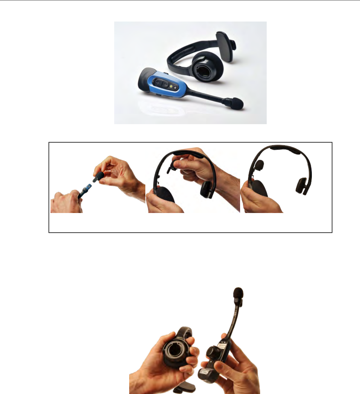
Figure 88: SRX2 headset and electronics module
Figure 89: Removing mic cap and stowing in mic cap pocket
Attaching the SRX2 Electronics Module to a Headband
1. Position the SRX2 electronics module with the button controls facing away from the headband.
2. Insert the speaker on the back of the electronics module into the pocket on the earpiece hub by aligning
the notches on the speaker and hub pocket.
Figure 90: Attaching the electronics module
3. Push the electronics module into the hub pocket until it is firmly seated.
Confidential: For informational use by Vocollect Resellers and customers only
Vocollect Wireless Headsets | 123
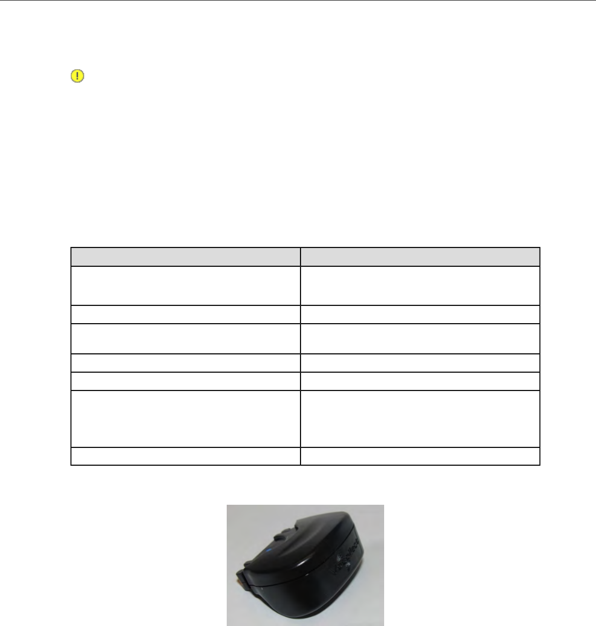
Removing the SRX2 Electronics Module from a Headband
Important: Do not squeeze the battery latches on the sides of the electronics module while removing
it from the headband. The battery may be inadvertently released from the electronics module.
1. Grasp the SRX2 electronics module with one hand, pressing your thumb and fingertips into the gap
between the electronics module and earpiece hub.
2. With the other hand, hold the headband by the earpiece hub.
3. Pull the electronics module away from the earpiece hub.
SRX2 Compatibility
Vocollect has tested the SRX2 Wireless Headset with the following devices and Vocollect Voice Software
versions. Support and compatibility of the SRX2 headset is not limited to these products, but the customer
assumes risks related to untested configurations.
Vocollect Voice SoftwareDevice
VoiceClient®3.8 and newer
VoiceCatalyst®1.1 and newer
Vocollect Talkman A500 and Talkman A500 VMT
VoiceClient 3.8 and newerVocollect Talkman T5 and Talkman T5m
VoiceCatalyst MP for Windows XP 1.0 and newerWindows XP PC and other supported display
terminals
VoiceClient MP 2.0 and newerIntermec®CK3
VoiceCatalyst MP for Windows XP 1.0 and newerIntermec CV61
VoiceClient MP 2.0 and newerPsion WORKABOUT Pro G2
Psion WORKABOUT Pro (WAP3)
Psion NEO
VoiceClient MP 2.0 and newerMotorola®MC9500
Charging the SRX2 Headset
Figure 91: SRX2 Wireless Headset High-Performance Battery
The SRX2 Wireless Headset is powered by a rechargeable lithium ion battery pack.
A fully depleted SRX2 Wireless Headset battery will be fully recharged in less than 6 hours. The headset
user will hear the following warnings when the battery charge is low.
Confidential: For informational use by Vocollect Resellers and customers only
124 | Vocollect Hardware Documentation
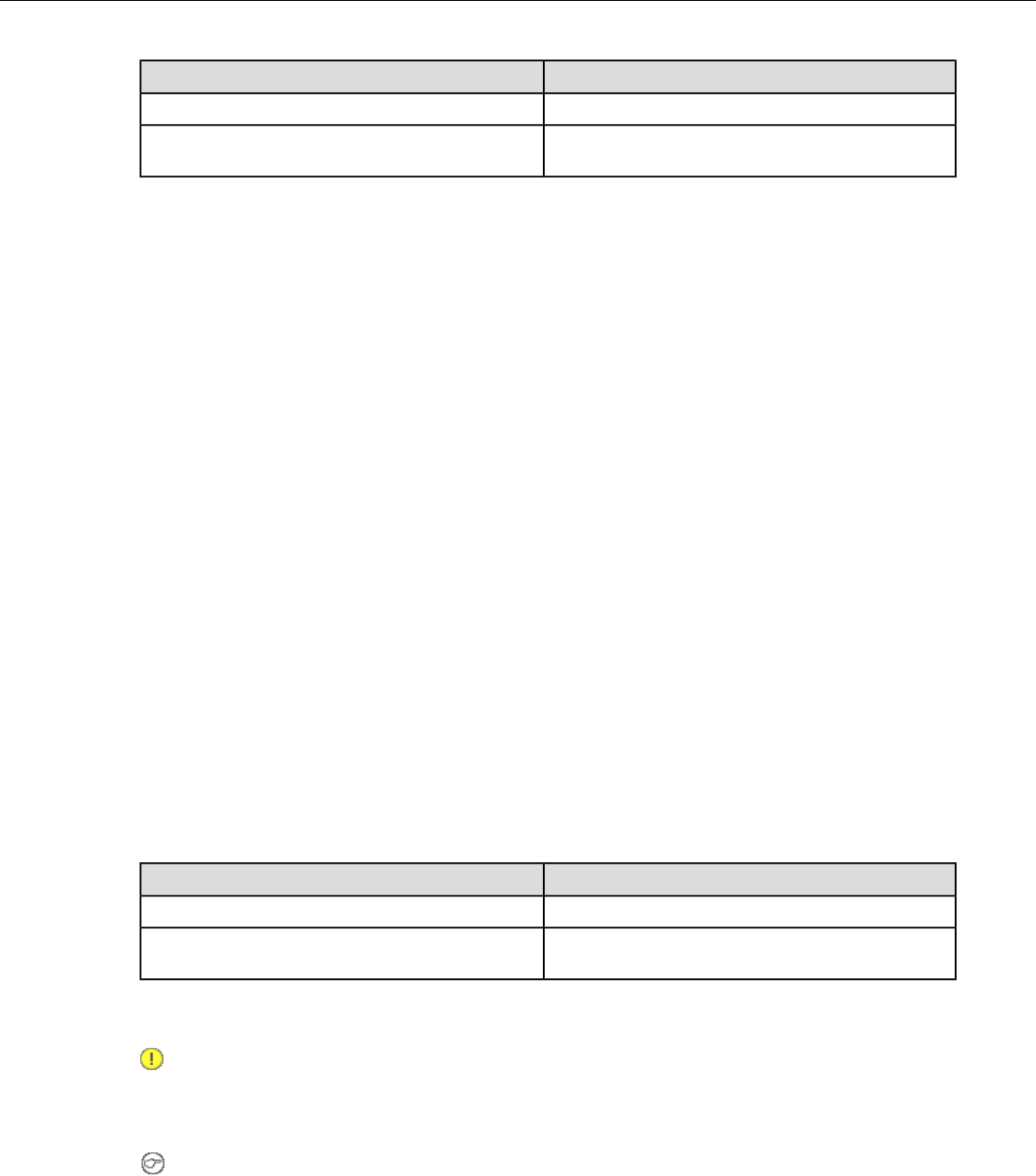
Audio WarningBattery Condition
"Headset battery is getting low."When battery voltage is low
“Headset battery is getting low. Change headset
battery now.”
When battery voltage is critically low and about
to turn off
SRX2 Battery Specifications
Electrical Specifications
• Cells: The battery pack uses a single lithium ion cell.
• Nominal voltage = 3.6V
• Watt hours = 2.7 WHr
• Protection circuit characteristics: The pack contains a protection circuit that prevents over and under
voltage conditions on the cell and protects the pack from damage as a result of a short circuit between
the positive and negative terminals of the battery.
• The battery pack contains custom electronics that provide performance, temperature, and pack
identification to the device. This information is made available to voice management software.
• Battery Charging: The battery pack must be charged only in a Vocollect designated charger.
Mechanical and Environmental Specifications
• Drop-test specifications: The battery meets the transient drop criteria.
• 24 drops at 6 feet (182.88 cm)
• 12 drops at 7 feet (213.36 cm)
• Environmental specifications: The battery functions properly in the following conditions:
Temperature: -22°F to 122°F (-30°C to 50°C)
Humidity: 95% non-condensing
Rain/dust: IP54
Battery Notifications
The SRX2 battery triggers two warnings based on remaining runtime:
Audio WarningBattery Condition
"Headset battery is getting low."When battery voltage is low
“Headset battery is getting low. Change headset
battery now.”
When battery voltage is critically low and about
to turn off
Charging SRX2 Wireless Headset Batteries
Important: Once an SRX2 battery is placed on a port in the charger, it must remain in the charger
for a minimum of five seconds. This allows the charger sufficient time to analyze the state of the
battery. Removing the battery during this five second interval may cause the LED indicator on the
charger to display an incorrect battery status.
Note:
• A battery is fully charged and can be removed from the charger when the ring LED indicator
light for that port on the charger is green.
Confidential: For informational use by Vocollect Resellers and customers only
Vocollect Wireless Headsets | 125
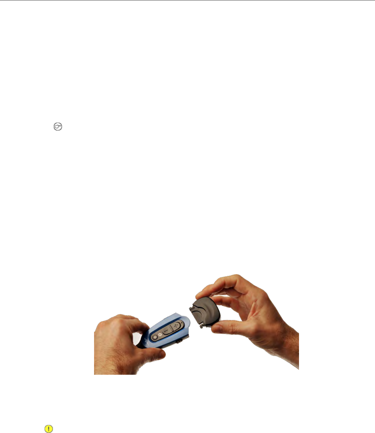
• If you insert a fully charged battery into a charger, the charger will analyze the battery's status
and then "top off" the battery's charge. The ring LED indicator light for that port will be yellow
during this process. When complete, the ring LED indicator will turn green.
1. Make sure the battery charger is powered. To power on the charger, connect the power supply to the
charger and a power source. The LED indicator light at the bottom right of the charger face panel
should be solid green.
2. Power off the headset by pressing and holding the Power button on the electronics module for
approximately one second.
3. Remove the battery from the headset electronics module.
4. Hold the battery with the Vocollect logo facing toward you, and push it onto an empty port on the
battery charger until it snaps into place.
5. Note: See the chart on SRX2 Battery Charger LED Indicators for more information on LED
patterns .
Make sure that the battery is properly mounted on the charger port. The ring LED indicator light
will turn yellow or green when the battery contacts connect to the charger port contacts. If the ring
LED blinks red, the battery is not seated properly. Remove the battery, and mount it on the port
again.
6. When the ring LED indicator turns a solid green, the battery is fully charged. Pull the battery off the
charger port to insert it into an SRX2 headset electronics module.
Inserting a Battery into the SRX2 Wireless Headset
1. Make sure the battery is charged. A battery is fully charged and can be removed from the charger
when the LED ring indicator on the charger port for that battery is green.
2. Position the headset electronics module with the buttons facing toward you.
3. Hold the battery with the label side down and contacts facing the open end of the electronics module
opposite the mic boom.
4. Push the battery onto the electronics module until it clicks in place.
5. Make sure the battery is firmly in place and cannot be removed without pressing the battery release
latches.
Removing a Battery from an SRX2 Wireless Headset
Important: Do not remove the battery from the SRX2 headset until the LED indicator on the
headset is off.
Confidential: For informational use by Vocollect Resellers and customers only
126 | Vocollect Hardware Documentation
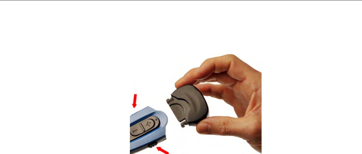
1. Power off the headset by pressing and holding the Power button on the electronics module for one
second.
2. Grasp the headset by the sides of the electronics module with your thumb and fingers on the black
battery latches.
Figure 92: Battery Latches for Removing SRX2 Battery
3. With your other hand, hold the battery at the end of the electronics module opposite the mic boom.
4. Press and hold both battery latches at the same time, squeezing them into the sides of the electronics
module until the battery releases from the electronics module.
SRX2 Battery Warm-Up Time
If a battery has been used in an extreme hot or extreme cold environment, charging will not start
immediately.
When the battery is placed in the charger, the battery port LED indicator will turn yellow. Charging
will only begin after the battery reaches the proper temperature range - 32° F (0° C) to 104° F (40° C).
It may take up to 30 minutes for the battery to reach a safe temperature.
If battery temperature does not come into range in about one hour, the red LED will blink indicating
that there is a charger fault.
Wearing an SRX2 Wireless Headset
1. Put the headset on and adjust the ear pad to fit snugly over your ear.
Confidential: For informational use by Vocollect Resellers and customers only
Vocollect Wireless Headsets | 127

Figure 93: Wearing the SRX2 headset
2. Position the t-bar directly above, and as closely as possible to, your other ear.
3. If installed, adjust the stability strap so it fits securely across the back of your head.
4. Rotate the electronics module up or down to position the microphone near your mouth.
Figure 94: Moving the Microphone Into Position
5. Make final adjustments with the flexible boom so that the microphone is positioned at the corner of
your mouth, about 1 inch (2.5 cm) away from your face.
Installing the Stability Strap on the SRX2 Wireless Headset
1. Hold the headset so that the earpad faces you and the electronics module faces away.
2. Locate the knob on the inside of the headband near the earpad.
3. Hold the strap so that the end with the hole fits over the knob on the headband, and press down
firmly so the knob comes all the way up through the hole.
Confidential: For informational use by Vocollect Resellers and customers only
128 | Vocollect Hardware Documentation
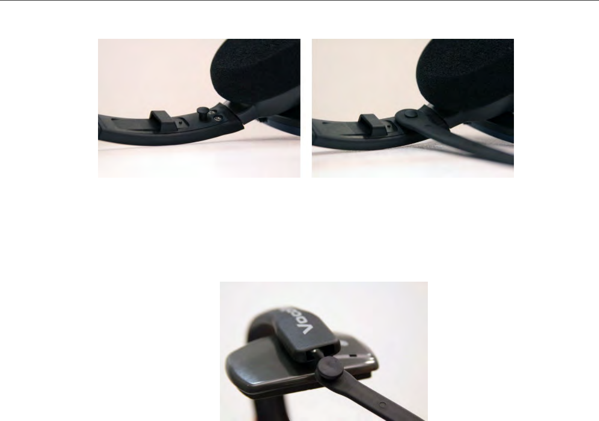
Figure 95: Pressing the strap onto the earpad side of the headband
4. Turn the headset so that the t-bar pad faces you.
5. Locate the slot on the end of the headband near the t-bar.
6. Align the knob at the free end of the strap with the slot on the headband.
7. Slide the knob into the slot until it snaps into place.
Figure 96: Inserting the strap into the headband slot
8. Position the strap to go around the back of your head. The strap swivels freely on the two knobs so
that it can be positioned at the back of the head for either right-ear or left-ear wearing of the headset.
Replacing an Earpad on the SRX2 Headset
1. Hold the headset so that the earpad faces you and the electronics module faces away.
2. Grasp the earpad and earpad plate assembly and rotate them to the left to unlock the plate from the
headband.
3. Lift the pad and plate assembly off of the headband.
4. Install the replacement pad.
a) Remove the ear pad by pulling it away from the ear pad plate.
b) Slide one side of the new pad over the edge of the ear pad plate and gently stretch the pad until
it covers the plate.
c) Ensure that the lip of the new pad completely covers the ear pad plate all the way around.
Confidential: For informational use by Vocollect Resellers and customers only
Vocollect Wireless Headsets | 129
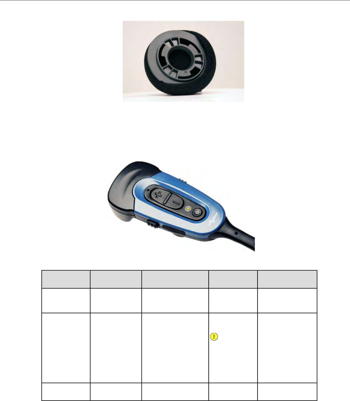
Figure 97: Installing a new earpad
5. Place the new earpad and earpad plate assembly onto the headset earpiece.
6. Rotate the assembly to the right pressing gently into the earpiece until the assembly locks into place.
Headset Functions and LED Patterns for SRX2
Figure 98: SRX2 User Interface
ToneLED PatternHeadset ModeUser ActionHeadset
Function
High pitch double
beep
Solid greenHeadset powers up in
low power pairing mode
Press Power
button for half a
second
Power on
Low pitch double
beep
Solid green, then
off
Headset powers offHold Power
button for one
second
Power off
Important:
Do not
remove the
battery until
the LED is
off.
Two tone ascending
sequence. If
N/AN/APress the Plus (+)
button
Increase volume
Confidential: For informational use by Vocollect Resellers and customers only
130 | Vocollect Hardware Documentation
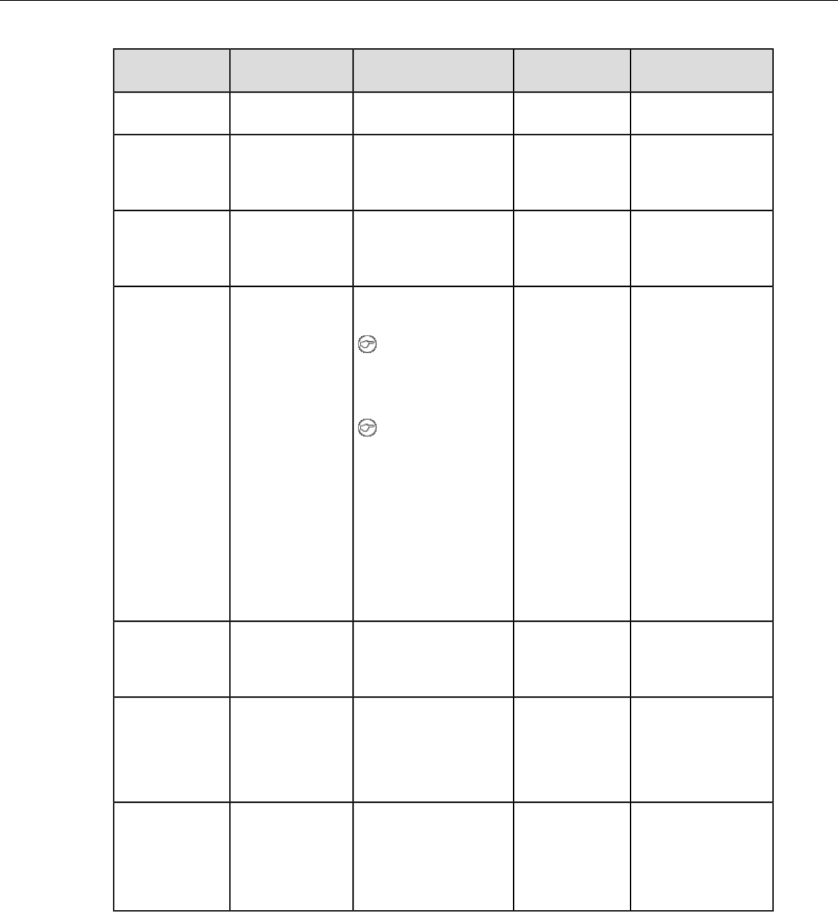
ToneLED PatternHeadset ModeUser ActionHeadset
Function
connected, device
says, "louder."
Two tone descending
sequence. If
N/AN/APress the Minus
(-) button
Decrease volume
connected, device
says, "softer."
No tone when
entering mode. Three
Solid greenHeadset disconnects
current pairing and
With headset
connected, press
Force disconnect
for manual
ascending tones upon
pairing with a device
enters low power
pairing mode
the Plus (+) and
Minus (-) buttons
pairing in low
power mode
No tone when
entering mode. Three
Rapid flash, then
solid green
Headset enters high
power pairing mode
With headset in
pairing mode,
press the Plus (+)
Switch to high
power pairing
when pairing in ascending tones upon
pairing with a device
Note: This mode is
recommended only
and Minus (-)
buttons
low power mode
has failed if low power pairing
fails.
Note: Vocollect
does not
recommend this
pairing mode for
Talkman devices.
This mode greatly
increases the
likelihood that your
headset will pair
with the wrong
device.
Three ascending
tones upon
Slow flashing
blue (on 25%, off
75%)
Headset connected as a
slave device
N/ANormal
operation, paired
and connected connecting to master
device
Three descending
tones when the
Slow flashing
green (on 25%,
off 75%)
Headset connectable but
not discoverable.
Any Bluetooth device
can connect if it knows
the headset's address.
N/APaired but
connection
dropped, possibly
out of range
connection to the
master device is
dropped
N/ASolid blue when
plugged in, off
Device updateConnect headset
to computer
Update headset
software
during update,running Vocollect
returns to solidHeadset Software
Update Tool blue when
update complete
Confidential: For informational use by Vocollect Resellers and customers only
Vocollect Wireless Headsets | 131

About Pairing Wireless Headsets
Pairing is the process in which two devices enabled with Bluetooth wireless technology create a secure
link in order to share information. The pairing process begins when the master device initiates an inquiry
to search for Bluetooth addresses or queries one, specific address.
Vocollect wireless headset pairings with Talkman or handheld devices are initiated by the device and
remain paired until broken by user action. Note that the pairing exists between the headset and device
hardware — the device operator ID is not tied to this pairing. If the operator moves to a different device,
the original headset/device pairing will not follow that operator.
Note: The automatic operator load feature is an exception to the hardware-only pairing. On supported
platforms, when an operator connects to a Vocollect wireless headset, that connection and operator
information are registered in VoiceConsole. The next time the operator connects to that headset;
his or her information will be loaded automatically. See the automatic operator load documentation
for your Vocollect Voice release.
Pairing versus Connecting
Pairing is not the same as connecting. Two Bluetooth devices, once paired, can connect and disconnect
many times. With a pairing in memory, the two devices can reconnect easily and will make repeated
attempts to establish a connection. In this way, a headset and device pairing allows for increased user
mobility.
For example, if the user takes the headset out of range of the paired device or powers it off, the device
will notice the connection loss, sever the connection, and then try to reconnect. The two remain paired
throughout this process.
SRX/SRX2 Headset Pairing Methods
After an SRX or SRX2 headset enters low or high power pairing mode, it is available to accept a pairing
initiated by a Talkman A500, Talkman T5-Series, or other Bluetooth-enabled device. These pairings can
be accomplished using a variety of methods:
On startup or on removal from a charger, the Talkman device immediately
searches for wireless headsets and initiates a pairing. Auto pairing is most
effective when users swap headsets and Talkman devices regularly.
Auto pairing:
Note: The first time an SRX headset accepts an auto pairing, the paired
device configures the headset to enter into pairing mode immediately on
all future startups.
Note: The SRX2 headset always powers up in pairing mode.
The user determines when to pair a device and headset by pressing buttons
on the device. Manual pairing is effective in environments where the same
Talkman devices and headsets are always used together.
Manual pairing:
Important: The first pairing for an SRX headset that has never been
paired with a device must be a manual pairing. After this first time, the
headset can pair automatically.
Note: The SRX2 headset can perform either manual or auto pairing for
its first pairing.
Confidential: For informational use by Vocollect Resellers and customers only
132 | Vocollect Hardware Documentation

The user pairs a specific device to a headset via the VoiceConsole interface.VoiceConsole pairing:
See Pairing a Headset by Screen-Based Pairing for details on pairing handheld
devices to a headset.
Screen-Based pairing:
Cross Pairing
Cross pairing is the result of a master device pairing with a headset or other device that is not the
intended slave. If a user cannot isolate his or her device and headset from others and a cross pairing
occurs, the user should break the existing pairing and retry the intended pairing.
Tip: Prevent unwanted cross pairing by isolating the device and headset from all other Bluetooth
devices any time that the device is performing an inquiry scan to find the headset.
Pairing an SRX Headset
Once paired, an SRX headset and a device remember their association, even when powered off and on
again or after the device recharges. The SRX headset will only connect with that paired device.
Pairing the SRX headset with a new device erases the previous pairing from the headset's memory.
Note: If you are using an SRX2 headset, see Pairing an SRX2 Headset for details.
Auto Pairing with a Talkman Device
Prerequisites:
• The headset is powered off. You can only put an SRX Wireless Headset into low or high power pairing
mode from the powered-off state.
• There is no wired headset connected to the Talkman device.
• The Talkman device is in sleep mode — not in use running a task or voice application. Its green LED
indicator is flashing. If the LED is solid green, press the Play/Pause button.
• The Talkman device is Bluetooth ready with Bluetooth connection features enabled.
Important: An unpaired Talkman device will constantly search for wireless headsets while in auto
pairing mode. Do not leave an auto pair-enabled device unpaired and powered on because the search
will drain the battery.
1. Reboot the Talkman device or remove it from a charger. Either of these two actions will initiate a
scan for headsets by the device.
2. If the LED indicator on the headset is not flashing slowly, then it is not in pairing mode. To enter
pairing mode, press and hold the Plus (+) and Minus (-) buttons on the headset control panel for four
seconds.
The LED indicator on the headset flutters quickly, plauses, flashes three times quickly, then starts
flashing slowly. The headset remains in pairing mode for about one minute then reverts to idle mode.
3. Hold the headset and Talkman device so they are within six inches of each other but not touching.
The blue LED indicator on the Talkman device turns on, may flash a few times, and then remains
lit. After 20 to 30 seconds, the headset beeps three ascending tones and its LED indicator flashes less
rapidly. These indicators confirm that a pairing has completed.
4. Put on the headset. You will hear the headset repeat the serial number of the Talkman device to
which it is paired.
5. Verify that the number matches the serial number on the Talkman device.
If you need to attempt the pairing again, re-enter pairing mode by rebooting the headset.
Confidential: For informational use by Vocollect Resellers and customers only
Vocollect Wireless Headsets | 133

6. Press the Play/Pause button on the Talkman device to confirm the number.
7. Press the Play/Pause button again to begin working.
Manually Pairing with a Talkman Device
Prerequisites:
• The headset is powered off. You can only put an SRX Wireless Headset into low or high power pairing
mode from the powered-off state.
• The Talkman device is not in a charger, and there is no wired headset connected to it.
• The Talkman device is in sleep mode — not in use running a task or voice application. Its green LED
indicator is flashing. If the LED is solid green, press the Play/Pause button.
• The Talkman device is Bluetooth ready with Bluetooth connection features enabled.
1. On the headset control panel, press and hold the Plus (+) and Minus (-) buttons for four seconds.
The LED indicator on the headset flutters quickly, plauses, flashes three times quickly, then starts
flashing slowly. The headset remains in pairing mode for about one minute then reverts to idle mode.
2. Press and hold the Plus (+) and Minus (-) buttons on the Talkman device for two seconds to manually
initiate a search for wireless headsets.
3. Immediately hold the headset and Talkman device so they are within six inches of each other but not
touching.
The blue LED indicator on the Talkman device turns on, may flash a few times, and then remains
lit. After 20 to 30 seconds, the headset beeps three ascending tones and its LED indicator flashes less
rapidly. These indicators confirm that a pairing has completed.
4. Put on the headset. You will hear the headset repeat the serial number of the Talkman device to
which it is paired.
5. Verify that the number matches the serial number on the Talkman device.
If you need to attempt the pairing again, re-enter pairing mode by press the Plus (+) and Minus (-)
buttons on the Talkman device again.
6. Press the Play/Pause button on the Talkman device to confirm the number.
7. Press the Play/Pause button again to begin working.
Screen-Based Pairing with a Handheld Device
Screen-based pairing is the preferred method for pairing an SRX headset with a handheld wireless device
or PC. This method allows the user to pick a specific headset from a list of available headset Bluetooth
addresses displayed on a screen, and eliminates the problem of unwanted cross pairing. Auto and manual
pairing processes are not available in screen-based pairing.
Prerequisites:
• The headset is powered off. You can only put an SRX Wireless Headset into low or high power pairing
mode from the powered-off state.
• The handheld device is not in a charger, and there is no wired headset connected to it.
• The device is in sleep mode — not in use running an application.
• The device is Bluetooth ready with Bluetooth connection features enabled.
1. On the SRX headset, press and hold the Plus (+) and Minus (-) buttons for four seconds to place the
headset in pairing mode.
Confidential: For informational use by Vocollect Resellers and customers only
134 | Vocollect Hardware Documentation
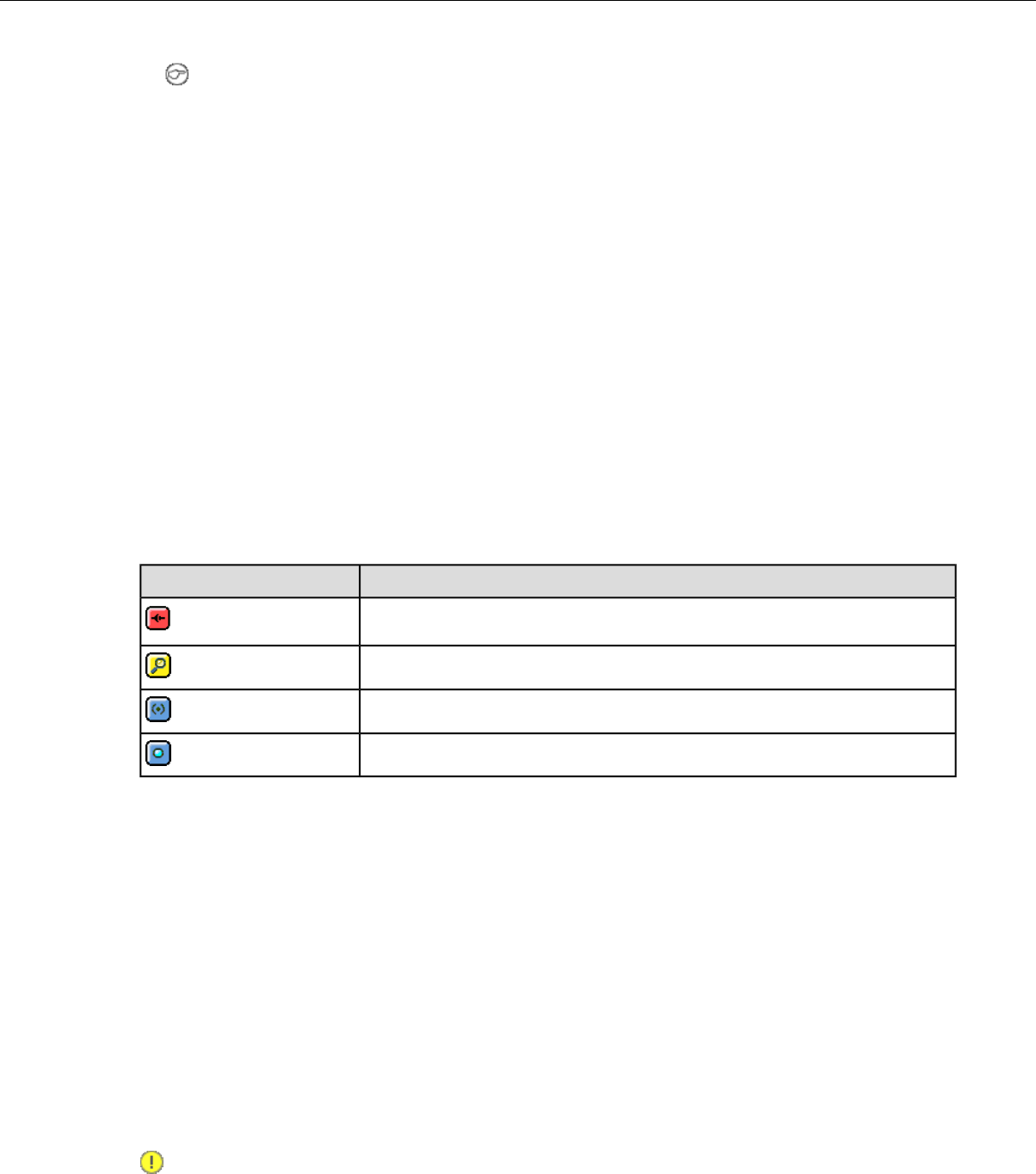
Note: Some handheld devices may require the headset to be in high power pairing mode in order
to be discovered in the device's pairing inquiry. To place the SRX headset in high power pairing
mode, press and hold the Plus (+) and Minus (-) buttons for seven seconds.
By setting the SrxHighPowerPairingDelaySeconds configuration parameter, you can configure
how long an operator must hold the Plus and Minus buttons before entering high-power pairing
mode or set the parameter to have the headset go directly into high-power pairing mode.
2. Initiate the pairing inquiry from the master device by pressing or clicking the appropriate button on
the screen.
3. Hold the headset and wireless device so they are within six inches of each other but not touching.
4. Select the ID number of the headset you want to use from the Select SRX Headset list on the screen.
5. Tap or click the appropriate button on the screen to create the pairing.
The screen briefly displays that the device attempts to connect to the headset . Once the headset
connects, three tones play in the headset, the SRX Headset Status displays as Connected. The pairing
confirmation step is skipped because the pairing was specified by the user.
6. Press the Play/Pause button to begin working.
Handheld Device Pairing Status Icons
When using the Vocollect Voice application on a handheld wireless device, an icon in the upper right
hand corner of the screen indicates the pairing status. Vocollect Voice on a PC displays similar
browser-based notifications, but the icons are different.
StatusIcon
A wireless headset is not paired to the device
The device is searching for a headset
The device is paired with a headset but not yet connected
The device is connected to the headset
Pairing an SRX2 Headset
The SRX2 Wireless Headset makes pairing and connecting even easier:
• It automatically enters low power pairing mode when it is turned on.
• It can break and re-enter pairing modes from a powered-on state.
• No headset reboot is necessary.
• It accepts connections from any device that was previously paired to it.
Auto Pairing with a Talkman Device
Prerequisites:
• The headset is powered off.
• There is no wired headset connected to the Talkman device.
• The Talkman device is Bluetooth ready with Bluetooth connection features enabled.
Important: An unpaired Talkman device will constantly search for wireless headsets while in auto
pairing mode. Do not leave an auto pair-enabled device unpaired and powered on because the search
will drain the battery.
Confidential: For informational use by Vocollect Resellers and customers only
Vocollect Wireless Headsets | 135

1. Reboot the Talkman device or remove it from a charger to initiate a scan for headsets.
2. Turn on the headset.
The headset will remain in pairing mode for ten minutes. If not paired within ten minutes, it powers
off.
3. Hold the headset and Talkman device so they are within six inches of each other but not touching.
The blue LED indicator on the Talkman device turns on, may flash a few times, and then remains
lit. After 20 to 30 seconds, the headset beeps three ascending tones and its LED indicator flashes
blue. These indicators confirm that a pairing has completed.
4. Put on the headset. You will hear the headset repeat the serial number of the Talkman device to
which it is paired.
5. Verify that the number matches the serial number on the Talkman device.
If you need to attempt the pairing again, re-enter pairing mode by pressing and releasing the Plus
(+) and Minus (-) buttons on the headset control panel.
6. Press the Play/Pause button on the Talkman device to confirm the number.
7. Press the Play/Pause button again to begin working.
Manually Pairing with a Talkman Device
Prerequisites:
• The headset is powered off.
• The Talkman device is not in a charger, and there is no wired headset connected to it.
• The Talkman device is in sleep mode — not in use running a task or voice application. Its green LED
indicator is flashing. If the LED is solid green, press the Play/Pause button.
• The Talkman device is Bluetooth ready with Bluetooth connection features enabled.
1. Turn on the headset.
The LED indicator is solid green. The headset remains in pairing mode for about one minute then
reverts to idle mode.
2. Press and hold the Plus (+) and Minus (-) buttons on the Talkman device for two seconds to manually
initiate a search for wireless headsets.
3. Immediately hold the headset and Talkman device so they are within six inches of each other but not
touching.
The blue LED indicator on the Talkman device turns on, may flash a few times, and then remains
lit. After 20 to 30 seconds, the headset beeps three ascending tones and its LED indicator flashes
blue. These indicators confirm that a pairing has completed.
4. Put on the headset. You will hear the headset repeat the serial number of the Talkman device to
which it is paired.
5. Verify that the number matches the serial number on the Talkman device.
If you need to attempt the pairing again, re-enter pairing mode by press the Plus (+) and Minus (-)
buttons on the Talkman device again.
6. Press the Play/Pause button on the Talkman device to confirm the number.
7. Press the Play/Pause button again to begin working.
Screen-Based Pairing with a Handheld Device
Screen-based pairing is the preferred method for pairing an SRX2 headset with a handheld wireless
device or PC. This method allows the user to pick a specific headset from a list of available headset
Confidential: For informational use by Vocollect Resellers and customers only
136 | Vocollect Hardware Documentation
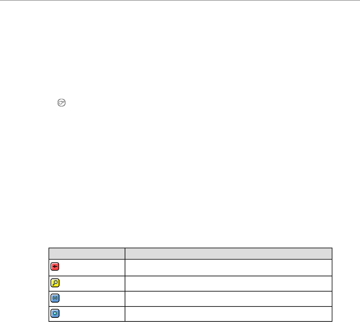
Bluetooth addresses displayed on a screen, and eliminates the problem of unwanted cross pairing. Auto
and manual pairing processes are not available in screen-based pairing.
Prerequisites:
• The headset is powered off.
• The handheld device is not in a charger, and there is no wired headset connected to it.
• The device is in sleep mode — not in use running an application.
• The device is Bluetooth ready with Bluetooth connection features enabled.
1. Turn on the SRX2 headset. The SRX2 headset starts up in low power pairing mode.
Note: Some handheld devices may require the headset to be in high power pairing mode in order
to be discovered in the device's pairing inquiry. To change to high power pairing mode, press and
release the Plus (+) and Minus (-) buttons on the headset while it is in low power pairing mode.
2. Initiate the pairing inquiry from the master device by pressing or clicking the appropriate button on
the screen.
3. Hold the headset and wireless device so they are within six inches of each other but not touching.
4. Select the ID number of the headset you want to use from the Select SRX Headset list on the screen.
5. Tap or click the appropriate button on the screen to create the pairing.
The device briefly displays that the device attempts to connect to the headset . Once the headset
connects, three tones play in the headset, the SRX Headset Status displays as Connected. The pairing
confirmation step is skipped because the pairing was specified by the user.
6. Press the Play/Pause button to begin working.
Handheld Device Pairing Status Icons
When using the Vocollect Voice application on a handheld wireless device, an icon in the upper right
hand corner of the screen indicates the pairing status. Vocollect Voice on a PC displays similar
browser-based notifications, but the icons are different.
StatusIcon
A wireless headset is not paired to the device
The device is searching for a headset
The device is paired with a headset but not yet connected
The device is connected to the headset
Pairing a Headset by VoiceConsole Pairing
The VoiceConsole pairing method should only be used if the device/headset pairing will be performed
once and never changed. While manual pairing can also result in this permanent pairing, VoiceConsole
eliminates the device inquiry step and begins paging immediately for the Bluetooth address.
Prerequisites:
• The headset is powered off.
• The device is not in a charger, and there is no wired headset connected to it.
• The device is in sleep mode — not in use running an application.
• The device is Bluetooth ready with Bluetooth connection features enabled.
Confidential: For informational use by Vocollect Resellers and customers only
Vocollect Wireless Headsets | 137

1. In VoiceConsole, click Devices and select the device for the pairing.
2. In Device Actions, select the actions for pairing to a peripheral, and complete the pairing. See
VoiceConsole Online Help for detailed instructions.
The pairing can be performed with the device powered off or while the device is running an application.
When the device powers up or goes into sleep mode, the paging process begins.
3. Place the headset in pairing mode.
• On an SRX headset: press and hold the Plus (+) and Minus (-) buttons for four seconds.
• On an SRX2 headset: press the Power button to turn it on.
4. When the two connect, the headset will play ascending connect tones. The pairing confirmation step
is skipped because the pairing was specified by the user.
5. Press the Play/Pause button to begin working.
More about SRX/SRX2 Pairing Modes
When a headset is in pairing mode it is ready to respond to any inquiries about its Bluetooth services.
The inquiring device uses this response to determine if it wants to pair with the headset. Because the
device is the initiator and the headset is the acceptor, a user facilitates the pairing process by putting
the headset into pairing mode before initiating the connection from the device.
SRX and SRX2 headsets support two pairing modes.
•Low Power Pairing Mode
Low power pairing mode is the default pairing mode for SRX and SRX2 headsets. In this mode, a
headset will answer a Bluetooth device inquiry with a very low power response that transmits within
a small area (a few feet or so, depending on the receiving capabilities of the inquiring device).
Limiting the wireless transmission helps to avoid an unwanted cross pairing (a pairing with a Bluetooth
address other than the target) by forcing the headset to be in close proximity to the device.
•High Power Pairing Mode
High power pairing mode allows the headset and device to be separated by more distance because
the headset’s response to inquiries is a wider transmission.
Vocollect recommends using high power pairing only if low power pairing fails. Use this mode with
care: While high power pairing mode makes it more likely that the connection will succeed, it also
increases the likelihood of cross pairing.
If the configuration parameter SrxAutoPairEnable is enabled and the configuration parameter
SrxHighPowerPairingDelaySeconds is set to 0, headsets will skip lower power pairing mode and
enter high power mode.
See Configuration Parameters for SRX/SRX2 Headsets for more details.
Placing Headsets in Pairing Modes
Pairing Mode ResultSRX2 ControlsSRX ControlsInitial Headset
State
Idle mode
Mode only allows connection
with the last device paired
N/APress and hold Plus (+) and
Minus (-) buttons for 0 to 3
seconds
Off
Confidential: For informational use by Vocollect Resellers and customers only
138 | Vocollect Hardware Documentation

Pairing Mode ResultSRX2 ControlsSRX ControlsInitial Headset
State
Low power pairing modePress and release Power
button
Press and hold Plus (+) and
Minus (-) buttons for 4 to 6
seconds
Off
High power pairing modeN/APress and hold Plus (+) and
Minus (-) buttons for 7 or
more seconds
Off
Current pairing broken and
headset enters low power
pairing mode
Press and release Plus
(+) and Minus (-)
buttons
N/AOn and paired
High power pairing modePress and release Plus
(+) and Minus (-)
buttons
N/AOn in low power
pairing mode
Breaking a Pairing
There are several methods to break a pairing between an SRX or SRX2 headset and a Bluetooth device.
A device can break a pairing with a wireless headset by initiating a new search
for headsets. The user can initiate the device query by holding down the Plus
From the Device:
(+) and Minus (-) buttons on the device. This method is useful if the user’s device
completes a cross pairing with the wrong headset; the user can initiate another
manual pairing.
VoiceConsole displays all Bluetooth pairings including SRX and SRX2 headsets,
Talkman devices, scanners, and printers. From the Edit Device page, you can
clear a pairing. You can do this with headsets as well.
From VoiceConsole:
The headset cannot break the pairing with the device. The user must break it
from the device by initiating another pairing.
From an SRX
Headset:
The SRX2 headset user can break any pairing by pressing the Plus (+) and
Minus (-) buttons.
If the paired device is running Vocollect VoiceCatalyst 1.2 and newer, the SRX2
headset signals the device that the pairing is being broken. With older versions
of Vocollect Voice, the pairing breaks only after it times out.
From an SRX2
Headset:
Headset Pairing FAQ
Q: My device accidentally paired with a different headset, what can I do?
A: Perform a manual pairing; it will break the connection and initiate another inquiry. Note that the
user should have his or her headset in pairing mode before performing this step so that the device can
find the headset when it searches.
Q: The users at my site do not have assigned headsets and devices, so they could get a different
headset at every shift. Which pairing process would you recommend?
A: Auto pairing would probably be the easiest, as it will quickly establish connections and, by default,
does not maintain those pairings.
Confidential: For informational use by Vocollect Resellers and customers only
Vocollect Wireless Headsets | 139

Q: The users at my site are assigned their own SRX or SRX2 headsets, so I want to maintain
pairings and avoid pairing headsets at the start of every shift. What pairing process would
you recommend?
A: You could use manual pairing or auto pairing with the configuration parameter
SrxPersistAutomaticPairing set to "1" and SrxClearPairingInCharger set to "0" in order to maintain
pairings through device reboots and recharging.
Q: Our users are spending a lot of time pairing. What methods would you recommend to
reduce the time it takes to pair headsets?
A: There are a number of solutions:
• Use a pairing mode that is not as susceptible to cross pairing - avoid using auto pairing.
• Ensure that users are isolated by some distance when the devices perform inquiry searches.
•Use manual pairing, rather than auto pairing, so that the searches are done only at the user’s request.
• Use low power pairing.
• If your users do not share headsets and devices, use manual pairing so that the device and headset
remain paired.
• If your users share headsets and devices, use auto pairing so that pairing hardware at each shift will
complete faster.
Supervisor Audio with SRX/SRX2 Headsets
Supervisor Audio is a feature that will allow a second party to listen to the conversation between a
Bluetooth-enabled Talkman device and a user with an SRX or SRX2 headset.
A supervisor wears a wired headset connected to the operator's device, then walks behind the operator
who is wearing a wireless headset paired with the same device. The supervisor must keep the operator's
device within range of the operator's wireless headset.
Note: This feature is designed to work with Vocollect Talkman devices. It may function properly
with other devices depending on the available processing power.
Supervisor Audio offers two listening modes.
• Combined audio - the user’s microphone audio and the text-to-speech (TTS) audio are combined and
streamed out of the wired audio port
• Device audio only - the TTS audio only is streamed to the second party
Enabling Supervisor Audio
To enable this feature, set the SrxSupervisorAudioEnable configuration parameter to the desired
mode. See Configuration Parameters for SRX/SRX2 Headsets for details.
• This feature should ONLY be used for debugging and when a user requires training or assistance.
This parameter should be turned off for optimal performance.
• Under normal operations, you cannot have a wired headset attached to the device when using an
SRX or SRX2 headset. This parameter overrides this requirement when enabled.
• To avoid disconnecting the wireless headset, pair and connect the Talkman device to the headset
first, then connect a wired headset.
Confidential: For informational use by Vocollect Resellers and customers only
140 | Vocollect Hardware Documentation

Configuration Parameters for SRX/SRX2 Headsets
Values & Setting
Location
DescriptionSupported
Devices
Parameter
True
False (default)
Determines whether or not the
Bluetooth portion of the radio
A500,
T5-Series
Bluetooth_IsEnabled
is receiving power. When the Set in VoiceConsole > Device
Profile or Edit Device
value for this setting is set to
false, the Bluetooth portion of
the radio receives no power,
and no other Bluetooth
parameters are active.
0 = disabled
1 = enabled
Enables automatic pairing
mode on SRX and SRX2
headsets.
This parameter is not
applicable for third-party
handheld devices.
A500,
T5-Series
SrxAutoPairEnable
The default setting depends
on the version of Vocollect
Voice software implemented.
If this parameter is set to 1
(enabled), the setting of
SrxClearPairingInCharger
is ignored
Set in task package,
operator profile, device
profile, or VRG file
0 = disabled
1 = enabled
Gives the user the ability to
force devices to clear the
A500,
T5-Series,
Psion,
Intermec
SrxClearPairingInCharger
If you enable this
parameter, the
headset Bluetooth pairing
from memory when placed into
a charger. SrxAutoPairEnable must be
set to 0 (disabled).
Note: In VoiceCatalyst
with Set in VoiceConsole > Device
Profile
SrxClearPairingInCharger
not set, the pairing is
cleared if
SrxAutoPairEnable is set
to 1. If
SrxClearPairingInCharger
is set to 0, it will prevent
the pairing from being
cleared when the device is
placed in a charger.
0 = disabled
1 = enabled (default)
Enables/disables use of SRX
or SRX2 wireless headsets
A500,
T5-Series
SrxHeadsetEnable
with approved Bluetooth
devices. Set in VoiceConsole > Device
Profile
Confidential: For informational use by Vocollect Resellers and customers only
Vocollect Wireless Headsets | 141
Values & Setting
Location
DescriptionSupported
Devices
Parameter
Users may prefer to disable
headsets when using other
Bluetooth peripherals.
1 to 10 seconds
(default is 6)
Specifies how long (in seconds)
an operator is required to hold
Psion,
Intermec
SrxHighPowerPairingDelaySeconds
the plus and minus buttons on Value can be 0 when
AutoPair is enabled for
headsets.
an SRX headset while in low
power pairing mode before
entering high power pairing
Set in VoiceConsole > Device
Profile
mode. Not used for SRX2
headsets.
0 = disabled (default for
Vocollect Voice versions
prior to VoiceCatalyst 1.2)
1 = enabled (default for
VoiceCatalyst 1.2 and
newer)
Enables a device to remember
the last automatically paired
headset after it has powered
down. Upon powering up, the
device attempts to connect to
that headset instead of going
into pairing mode.
A500,
T5-Series,
Psion,
Intermec
SrxPersistAutomaticPairing
Set in VoiceConsole > Device
Profile
Note: When the device is
placed into a charger, the
pairing will still clear as
in normal functionality.
This parameter is ignored
if the SrxAutoPairEnable
configurable parameter is
disabled.
0 = disabled (default)
1 = play mixing of TTS and
mic data
Enables/Disables the ability
to listen in on both sides of the
SRX Wireless Headset
A500,
T5-Series
SrxSupervisorAudioEnable
conversation through the use 2 = play the TTS audio only
of a remote listening kit or
Set in VoiceConsole > Device
Profile
wired headset plugged into the
device.
Note: Due to increased
bandwidth required by
Supervisor Audio mode,
headset audio
performance may sound
degraded while
Supervisor Audio is
enabled. For optimal
performance, be sure the
parameter is set to "0"
(disabled) during all
regular SRX wireless
headset use.
Confidential: For informational use by Vocollect Resellers and customers only
142 | Vocollect Hardware Documentation

Check the documentation for your release of Vocollect Voice software to verify if these settings are
supported.
Care and Use of Headsets and Microphones
The headsets and microphones used with the Vocollect Voice system are delicate pieces of electronic
equipment. Proper care and use of these products will ensure that they work well for a long time.
Important: For maximum hygiene, Vocollect discourages sharing headsets among operators.
The design of the SRX2 Wireless Headset features an electronics module that can be removed from
the headband and windscreen. The electronics module can be shared among operators over multiple
shifts, providing some level of hygiene while potentially reducing costs.
Wearing Headsets: General Procedures
This describes the standard procedures for wearing Vocollect headsets. Note that special types of headsets
have somewhat different procedures.
Tip:
Always use pads and windscreens with Vocollect headsets to protect the equipment and ensure
optimum speech recognition performance.
1. Put the headset on and adjust the ear pad to fit snugly over your ear.
•For the Hard-Hat Headset, first insert the headset bracket into the left or right slot on the hardhat,
then put on the hardhat.
2. Swing the microphone into position with the rotating lever at the earpiece.
Important: Do not swivel the microphone boom by the flexible end. Use the rotating lever on
the outside of the earpiece.
3. Make final adjustments with the flexible boom so that the microphone is positioned at the corner of
your mouth.
A dot or the word "talk" on the microphone faces your mouth when the microphone is positioned
properly.
Make sure that there is a windscreen on the microphone. A windscreen improves performance.
4. Clip the headset wire to collar and belt. Let the wire fall down your back, and clip it to the belt near
the device.
If you use a device cover, Vocollect recommends that you clip the bottom clip directly onto the cover.
5. Connect or pair the headset to the device.
Adjusting Headsets for Comfort
Vocollect has designed the SR Series headsets based on data for most head shapes and sizes. Because
the headset is the most personal piece of voice equipment and must remain stable while workers perform
very physical tasks, users may benefit from these headset adjustment guidelines.
•Placement of the "T-bar" pad: The SR-20, SR-21, SR-30, and SRX models have pads called "t-bars"
opposite the speaker side of the headset. The t-bar should be positioned on a part of the head with
the least amount of muscle.
Confidential: For informational use by Vocollect Resellers and customers only
Vocollect Wireless Headsets | 143
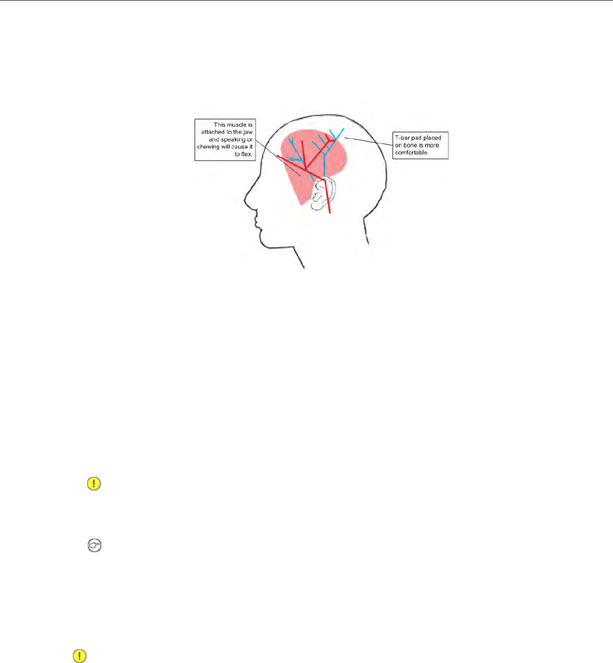
As an operator speaks, the muscle above the ear flexes. If the t-bar is placed on this muscle, the
headset applies pressure to the artery and nerves beneath it and can cause the operator some
discomfort. The operator can locate this muscle by moving his or her jaw and feeling the area above
the ear for movement. Some operators choose to alternate the headset position on either side of their
heads during their shifts.
Figure 99: T-bar Pad Placement on the Head
•Headset pad options: Vocollect offers a variety of pads to meet the unique requirements of workers
and working conditions.
Standard foam pads: provide cushioning and soft surfaces wherever the headset comes in contact
with the operator. Available on all headsets.
Leatherette ear pads: have a faux leather exterior that is a more firm and supportive and more
moisture resistant than standard foam pads. Offered for all SR-20 through SR-40 models.
Memory foam pads: offer superior cushioning support and comfort. Available in earpads for the
SR-20/21 and in t-bar pads for the SR-20/21 and SR-30.
Removing Headsets
1. Disconnect the headset from the device.
Important: Do not pull on the headset's cord.
2. Unclip the headset cord from your shirt or jacket.
3. Carefully remove the headset from your head.
Note: For the Hard-Hat Headset, remove the hard hat. Press the release clip to remove the
headset unit from the hardhat bracket.
Cleaning Windscreens
Vocollect recommends that you change windscreens every 90 days for optimum speech recognition
performance.
Important: Soap, cleaning solutions, and vigorous washing will remove the protective coating on
the windscreen and decrease its effectiveness.
1. Remove the windscreen from the microphone.
2. Rinse the windscreen under warm water.
Confidential: For informational use by Vocollect Resellers and customers only
144 | Vocollect Hardware Documentation

3. Squeeze out the excess water and let it air dry thoroughly.
Cleaning Headsets
Note: Commercial cleaning solvents are not recommended.
• Clean the plastic parts of the headsets with a soft cloth dampened with water. To clean and disinfect
the headset plastic, use a pre-moistened alcohol wipe.
•If the Talkman Connectors or plugs become contaminated, use a pre-moistened alcohol wipe to remove
dirt or residue.
•If the metal connection points on the Talkman's Connectors become discolored, use a soft pencil eraser
to clean them.
• Do not use unapproved liquids to clean the yellow, blue, and red Talkman Connectors (TCOs) and
any associated headset, scanner, or device plugs.
Cleaning the Headband Pad
Note: Vocollect strongly recommends that you leave the headband pad in place when cleaning it.
If you must remove the entire pad to clean it, use care to line up the headband pad with the topmost
part of the headband when you place it back on the headband.
• Leave the headband in place and simply wipe the headband with a soft cloth. If necessary, use a
pre-moistened alcohol wipe to clean and disinfect the unit.
Confidential: For informational use by Vocollect Resellers and customers only
Vocollect Wireless Headsets | 145
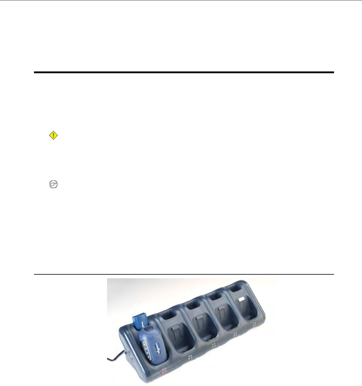
Chapter 9
Chargers
Vocollect offers charger units that can charge one or more batteries individually or while inserted in
Talkman devices.
Talkman devices should be placed into a charger when not in use. The charger charges the device's
battery while linking to the host computer to download new voice applications, reconfigure device settings,
and update device software.
Caution:
• Keep water and moisture away from the charger at all times. If a battery has any condensation
from use in a cold environment such as a freezer, dry the battery before placing it into the charger.
• Only Vocollect-approved batteries should be placed in the battery charger. Do not attempt to
charge any other type of battery in the charger.
Note:
• Do not place a device into a charger without a battery attached to it.
• A device is always on when it is in a charger. When a device that is powered off is placed into a
charger, it automatically turns on.
• The A500/T5 and T1 chargers can charge batteries both inserted in and separate from devices.
• Vocollect recommends that a protective device, such as an uninterruptible power supply with
surge protection and lightning arrestor capability, be used with battery chargers.
T5/A500 Combination Charger
Figure 100: T5/A500 10-Bay Combination Charger
• The T5/A500 10-Bay Combination Charger can store five devices at a time and any combination of
T5, T5mand A500 device models.
• The charger can store and charge ten batteries - five batteries in the upper battery slots and five
batteries connected to devices in the lower device slots.
Confidential: For informational use by Vocollect Resellers and customers only

• The charger can also share one device's configuration with other devices being charged at the same
time.
• The T5/A500 charger may be fixed to a wall using the available wall mount kit.
Note: Do not place a device into a charger without a battery attached to it.
If a device that has been on and in use for more than eight hours will automatically power off and
then back on after it has been in the charger for five minutes. Also, a device that has been in a
charger for more than eight hours will automatically power off and then back on.
T5/A500 Single-Bay Combination Charger
• A T5/A500 Single-Bay Combination Charger is also available. It includes one battery slot and one
device slot. The charger can store one device at a time and store and charge up to two batteries at a
time - one battery in the upper slot and one battery in the device in the lower slot.
T5/A500 10-Bay Combination Charger Specifications
21.21" (53.9 cm)Length
6.64" (16.9 cm)Depth
6.89" (17.5 cm)Depth with Wall Bracket
6.12" (15.5 cm)Height
Input Voltage: 100-250 Vac
Input Current: 2.4 A maximum
Power
Line Frequency: 50-60 Hz
Uses standard IEC 60320 plugCord
50° to 140° F (10° to 40° C)Operating Temperature
-22° to 158° F (-30° to 70° C)Storage Temperature
Functional to 90% non-condensingHumidity
Easy Configuration
Easy Configuration uses the serial connection between bays in the T5/A500 Combination Charger to
distribute configuration files from one device to all devices in the charger. This feature allows new
installations to quickly complete initial device configuration and simplifies adding new devices or
returning repaired devices to service.
Any of the supported device models - T5, T5m, and A500 - may be configured using this feature. Multiple
models may be configured in the charger at the same time. Please note, however, that some configurable
parameters are specific to a device's radio card. Therefore, some parameters loaded from the master
device to devices with different radios will not be effective, and devices that receive the distribution may
not receive all of the desirable parameters for their specific radios.
Note: Easy configuration should be used only with a DHCP server.
Easy Configuration: Initial Setup
The following instructions are for initially setting up the site. That is, no devices are currently connected
to VoiceConsole.
Confidential: For informational use by Vocollect Resellers and customers only
148 | Vocollect Hardware Documentation

1. Create a device profile in VoiceConsole.
2. In the Advanced Device Settings text box, type this parameter: "distributable"="1"
The value of "1" marks the device profile as one that can be shared with other devices using the serial
connection between bays in the T5/A500 charger. If this parameter is not placed in the device profile
or if its value is set to zero, the device profile will not be shared.
3. Follow the instructions in the VoiceConsole online help for completing the device profile.
Note: The AC power indicator at the bottom right of the charger displays alternating green and
yellow lights when Easy Configuration operations are occurring. Devices should not be removed
until the individual indicator on the device blinks green or the charger's power indicator glows
solid green.
4. Use a serial cable to load this profile to a device.
Note: If the device profile you are loading is configured for use with static IP addresses, all the
devices will have the same IP address.
Easy Configuration: Bringing Additional Devices Online
A single device has been configured using the Easy Configuration Initial Setup instructions and
VoiceConsole Online Help. The following instructions are for configuring additional devices.
1. Place a properly configured T5, T5m, or A500 device in the transmit bay in the charger. When facing
the charger bay, the transmit bay is the first bay on the right. It is identified with an off-white latch.
The other bays have dark gray latches.
2. Place the new or repaired T5, T5m, or A500 devices in the remaining charger bays.
• The LED indicators on the unconfigured devices flash green until the devices determine that they
cannot reach VoiceConsole.
• The LED indicators flash orange as the devices attempt to connect to the network to listen for a
file broadcast.
• The LED indicators flash green briefly as the devices receive profiles from the configured device
and verify the configuration.
• The LED indicators change to solid red as the devices reboot.
• When the devices have applied the configuration file and successfully contacted VoiceConsole, the
LED indicators change to blinking green. The devices are then ready to use or can be used in
another charger to bring additional devices online.
Note: The AC power indicator at the bottom right of the charger displays alternating green and
yellow lights when Easy Configuration operations are occurring. Devices should not be removed
until the individual indicator on the device blinks green or the charger's power indicator glows
solid green.
T5/A500 Combination Charger Power Supply Specifications
10-Bay Combination Charger Power Supply
Input Voltage: 100-250 Vac
Input Current: 2.4 A maximum
Input:
Line Frequency: 50-60 Hz
Output: 97.5 W (15 V x 6.5 A)Output:
Confidential: For informational use by Vocollect Resellers and customers only
Chargers | 149
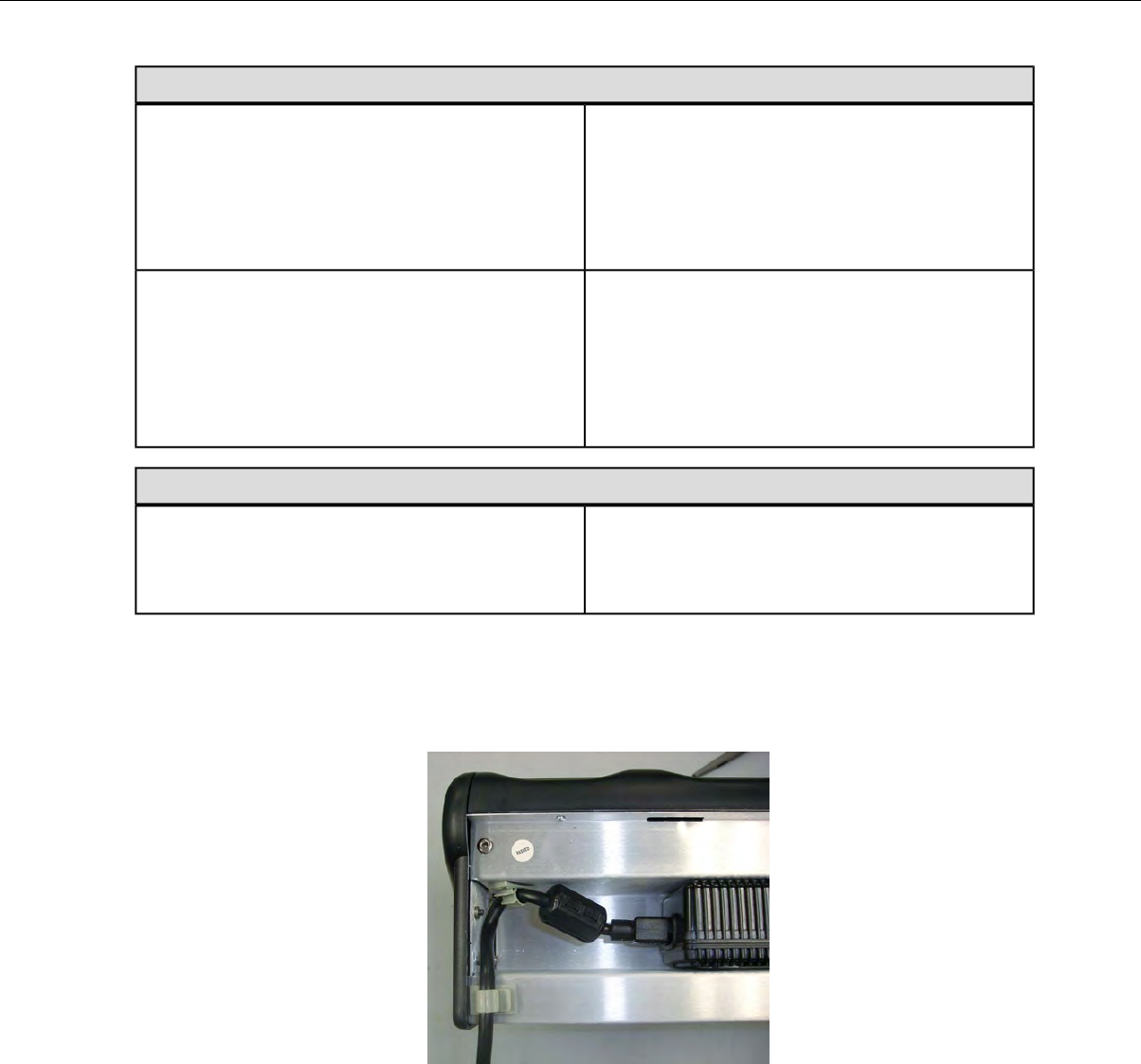
10-Bay Combination Charger Power Supply
UL listed and CSA certified
3 conductor 18 AWG
Cord (U.S., Mexico, Canada):
Terminated with a molded on plug cap rated at
125V 15A
Six feet minimum length
Internationally harmonized and marked <HAR>
3 conductor 0.75mm minimum wire
Cord (other countries):
Rated at 300V with PVC insulated jacket
Mounded on plug cap rated 250V 10A
Six feet minimum length
Single-Bay Combination Charger Power Supply
Input Voltage: 100-240 Vac
Input Current: 0.6 A maximum
Input:
Line Frequency: 50-60 Hz
Connecting the Power Supply to the T1 10-Bay Charger
1. Connect the AC cord to the left end of the power supply that is mounted inside the charger.
2. Route the cable through the plastic clips as shown.
Figure 101: Cable Routed Through Plastic Clips
3. Push the clips to lock the cord in place.
T5/A500 Combination Charger Wall Mount
This unit provides a convenient surface for mounting the T5/A500 10-Bay Combination Charger and its
power supply on a wall.
• Customer assembly required.
• Be aware of potential hazards (electrical wires, waterlines, etc.) when drilling the pilot holes.
Confidential: For informational use by Vocollect Resellers and customers only
150 | Vocollect Hardware Documentation
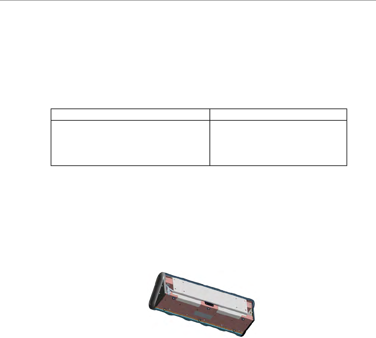
• Customer assumes all responsibility for the installation of these units.
• A device charger cannot have another charger placed directly above it. A section of dry-erase board
(included) must be placed above each device charger.
• If you drill into a wall stud when drilling a pilot hole for one of the anchors, do not use an anchor with
that hole.
• The lowest anchor for each extrusion must be a minimum of 12 inches from the floor.
• Avoid blocking power outlets and other wall receptacles when installing the extrusions and charger
unit.
Installing the T5/A500 Charger Wall Mount
You will needParts
• Drill with 1/8” bit• 1 mounting bracket
• •4 self-drilling screw anchors #10 Screw driver, #2 Phillips
•• Drilling template sheet (included)4 washers, #10 flat, type B regular
• 4 screws, #10 Phillips pan head
1. Using the drilling template, mark four holes for the anchors. Note that there are two sets of pilot
markers; one set for wall studs with 12 inch centers and one set for wall studs with 16 inch centers.
The bottom anchor holes must be at least 12 inches from the floor.
2. Drill the pilot holes for the anchors, and screw the anchors into the holes.
3. Position the mounting bracket so that its flat side is against the wall, aligned with the anchors, and
the mounting pins are away from the wall.
4. Insert a screw through a washer and a hole in the bracket, then into the anchor. Tighten screw.
Repeat for remaining screws.
5. Tilt the charger back and slide it onto the wall by lining up the tabs on the top of the bracket with
the notches in the back of the charger.
6. Level the charger so the supports on the bottom of the bracket are underneath the charger.
Figure 102: Supports Underneath Charger
About LED Indicators
Vocollect Talkman devices, SRX and SRX2 headsets, and their chargers have LEDs that indicate the
state of the equipment. These LEDs may be on, off or blink. In some cases an LED will blink, alternating
between two colors.
If the LEDs indicate that there is a problem, refer to information on troubleshooting to solve the problem.
See also Troubleshooting Problems Indicated by LED.
Confidential: For informational use by Vocollect Resellers and customers only
Chargers | 151
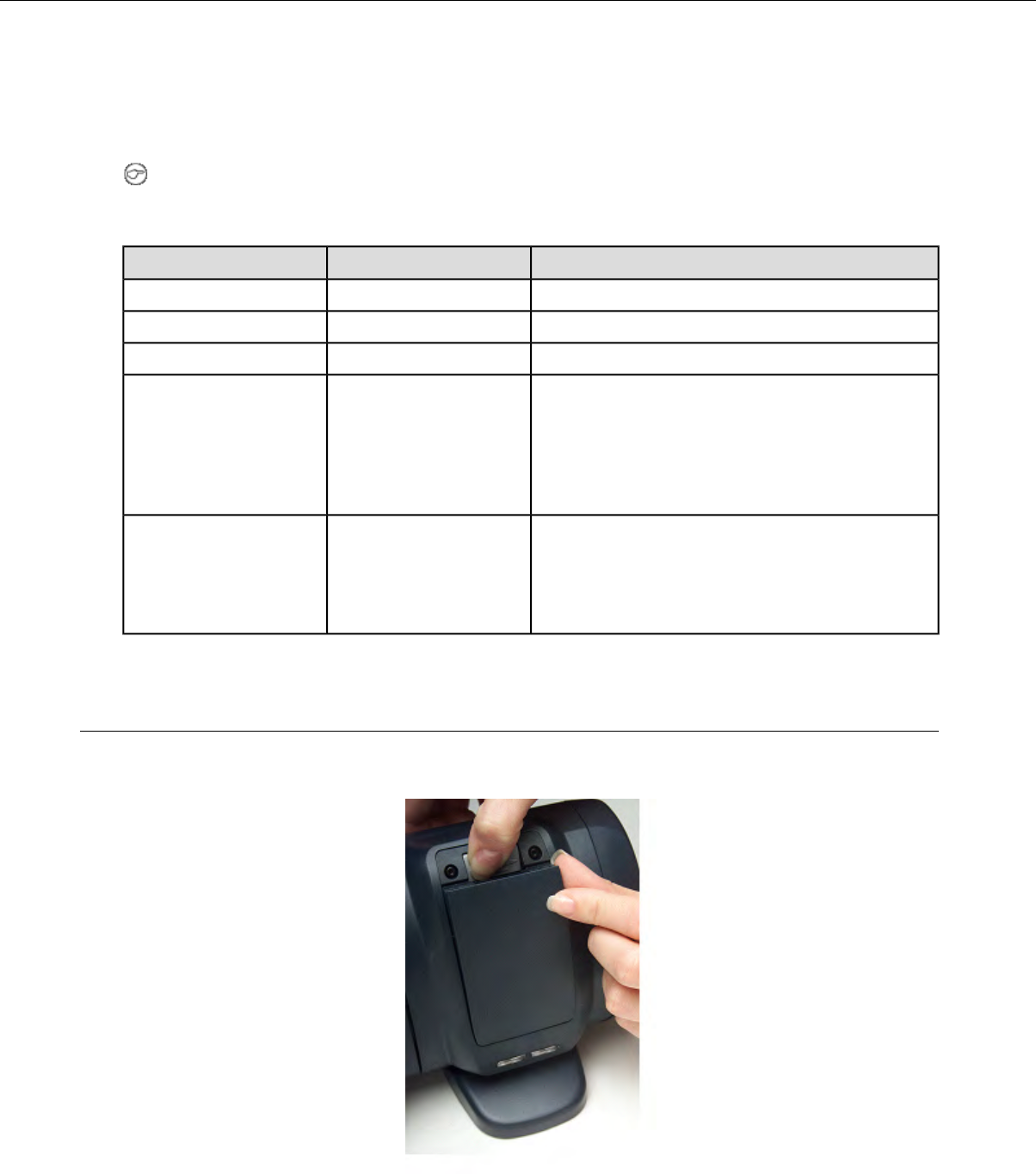
A500, T5 and T5m Device Charger LED Indicators
The upper pair of indicators applies to the charger's battery slots. The lower pair applies to the device
slots. The LED conditions described here apply to the lower pair.
Note: If there is no device in the charger or if the device in the charger does not have a battery and
one of these conditions occurs,disconnect the charger from its power source for about five seconds,
then reconnect the charger. If the condition persists, return the charger for service.
If a device with a battery is the charger...Right Indicator ColorLeft Indicator Color
Troubleshoot the problemOffOff
The battery is charged and ready to use.GreenGreen
The battery is being charged.OffRed
The battery may not be inserted into the charger
correctly.
OffBlinking Red
If the LED continues to blink red after inserting
the battery into the charger correctly, troubleshoot
the charger.
The battery may not be inserted into the charger
correctly.
YellowOff
The battery may be too hot or too cold. Wait for the
battery's temperature to normalize.
T2 Series Battery Chargers
T2 series device batteries can be charged in the device charger. A separate battery charger is also available
to charge spare batteries.
Figure 103: T2 Series Battery Charger
Confidential: For informational use by Vocollect Resellers and customers only
152 | Vocollect Hardware Documentation
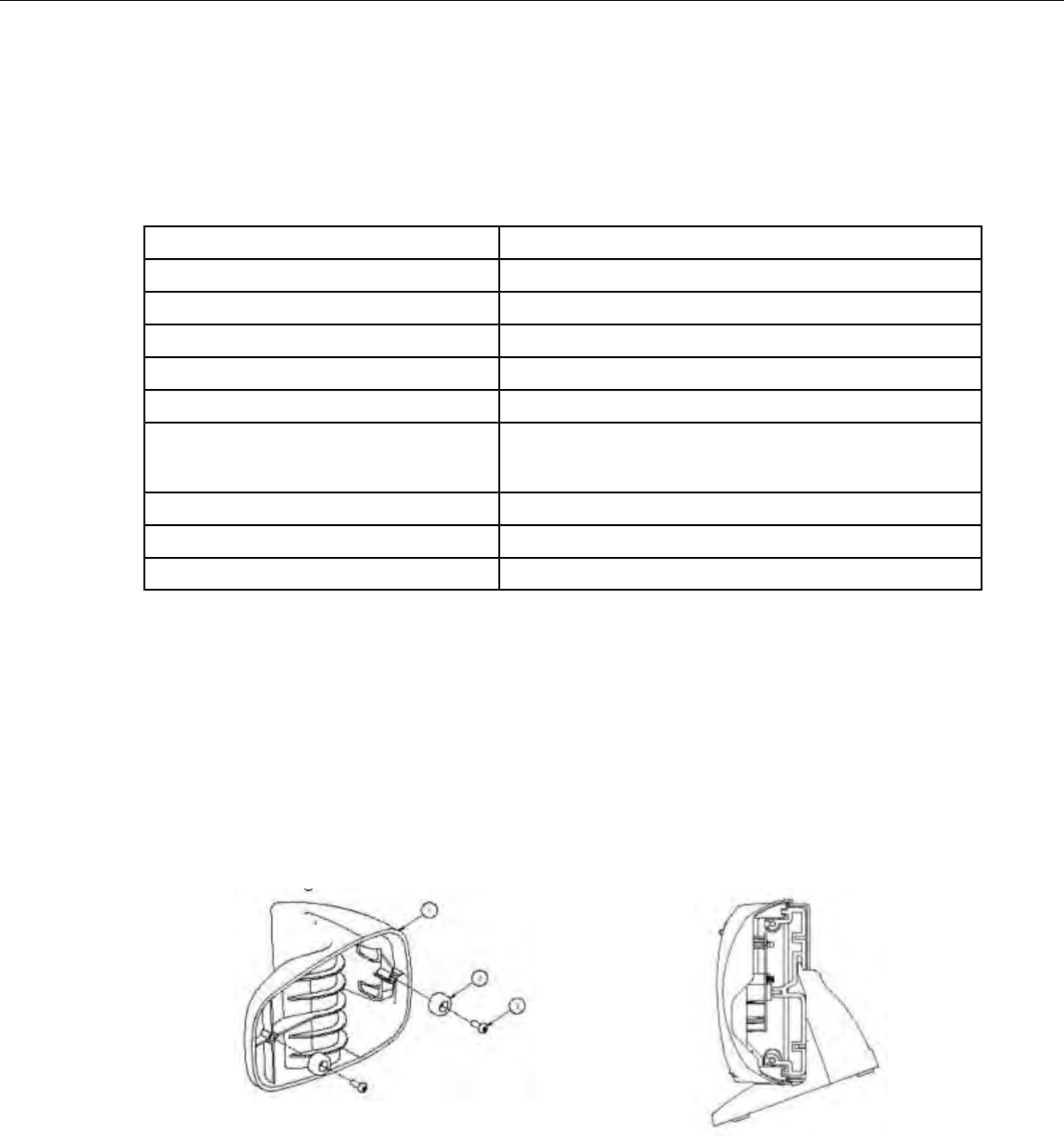
• The T2 series battery charger includes five battery slots. The charger can be used to store and charge
up to five batteries at a time.
• Wall mounts are available that can accommodate a single charger, multiple chargers, and battery
chargers.
T2 Series Battery Charger Specifications
Approximately 24" (61 cm)Length
Approximately 24" (61 cm)Length with Desk Mount Feet
Approximately 2.5" (6.5 cm)Width
Approximately 5" (12.7 cm)Width with Desk Mount Feet
Approximately 5.25" (13.3 cm)Height
Approximately 5.375" (13.65 cm)Height with Desk Mount Feet
90-264 Vac 50/60 Hz 72 W
Uses standard IEC 630 cord
Power
50° to 140° F (10° to 40° C)Operating Temperature
-22° to 158° F (-30° to 70° C)Storage Temperature
Functional to 90% non-condensingHumidity
Assembling the Stands for the T2 Charger
You will need a #2 Phillips screwdriver
Parts list:
• Charger stand(s)
• 2 rubber feet per stand
• 4 Phillips screws per stand
1. Secure the rubber feet to the stand with the screws.
2. Position each stand so that its top lip is inserted into the center channel in the back of the charger.
Figure 105: Positioning the stand on the charger
Figure 104: Attaching the feet
3. Secure each stand to the charger by inserting screws through the holes in the stand and screwing
them into the slot on the bottom of the charger.
Confidential: For informational use by Vocollect Resellers and customers only
Chargers | 153
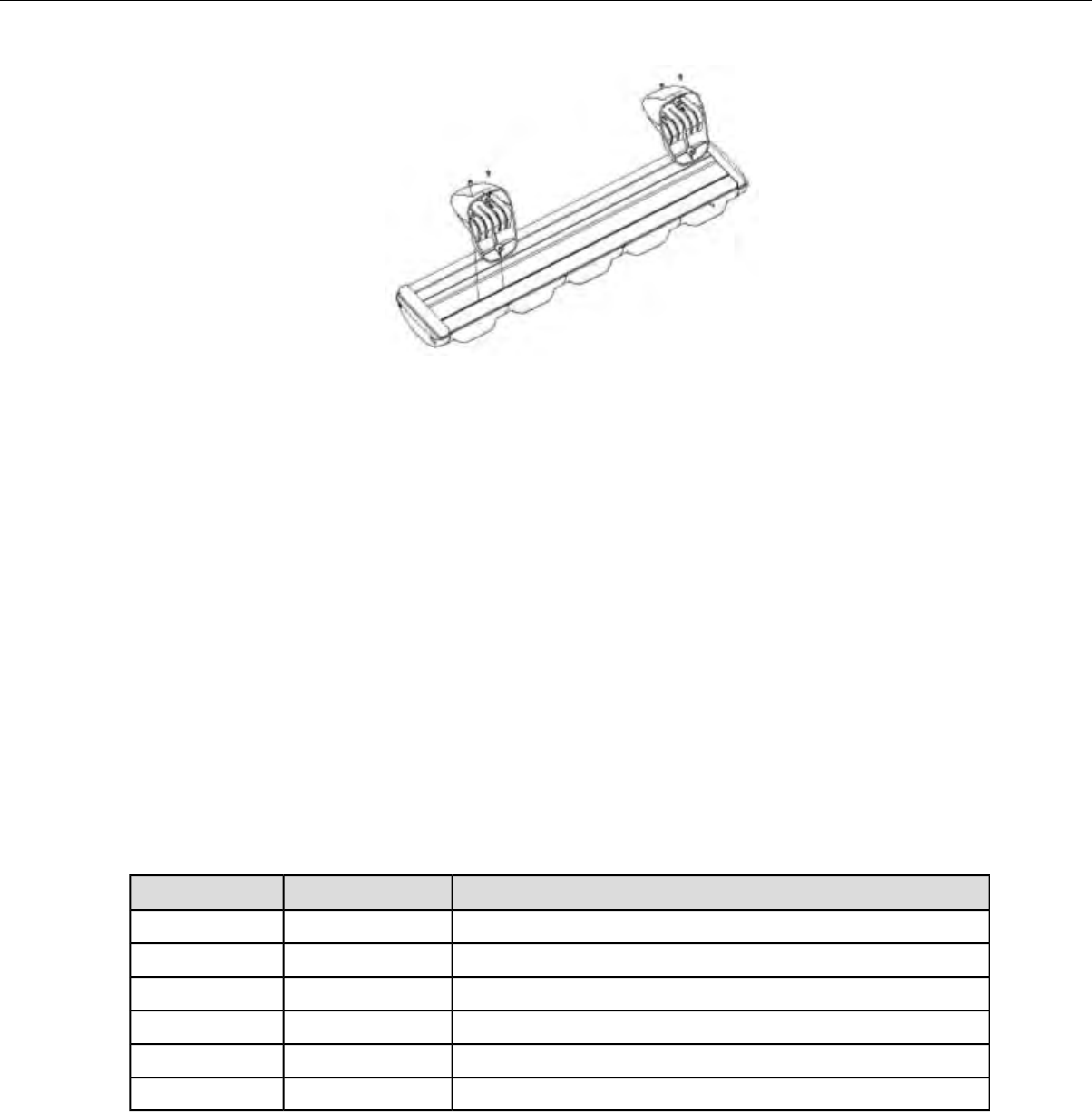
Figure 106: Screwing the stand into the charger
Charger Wall Mount, Multiple Chargers: T2 Series
This unit provides a convenient surface for mounting five charger units and their associated power
supplies on a wall.
• Customer assembly required.
• Be aware of potential hazards (electrical wires, waterlines, etc.) when drilling the pilot holes.
• Customer assumes all responsibility for the installation of these units.
• A device charger cannot have another charger placed directly above it. A section of dry-erase board
(included) must be placed above each device charger.
• If you drill into a wall stud when drilling a pilot hole for one of the anchors, do not use an anchor with
that hole.
• The lowest anchor for each extrusion must be a minimum of 12 inches from the floor.
• Avoid blocking power outlets and other wall receptacles when installing the extrusions and charger
unit.
Charger Wall Mount, Multiple Chargers: Mounting the Extrusions
Parts List:
DescriptionQuantityItem #
Extrusion21
Self-drilling screw anchor #882
Washer, #8, flat, type B regular83
Screw, #8x1.5 Phillips pan head84
Screw, #10-24x.312 hex, socket head25
Drilling template sheet16
You will need:
• Drill with 1/8” bit
• Screw driver, #2 Phillips
• Allen key, Hex 1/8”
1. Using the drilling template, mark eight holes on the wall for the anchors.
Confidential: For informational use by Vocollect Resellers and customers only
154 | Vocollect Hardware Documentation
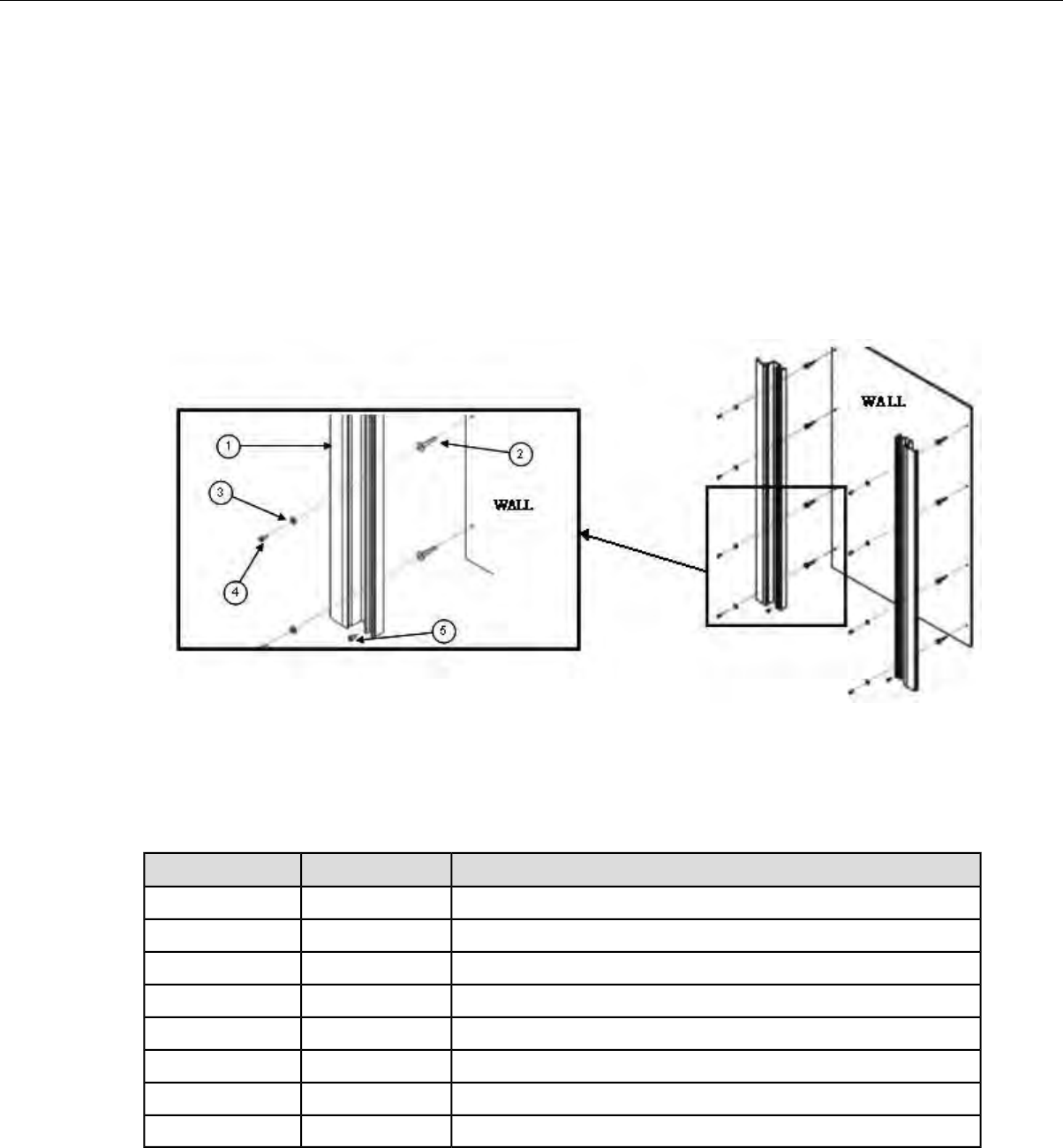
The bottom anchor holes must be at least 12 inches from the floor.
2. Drill the pilot holes for the anchors, and screw the anchors into the holes.
3. Align the holes of an extrusions with the installed anchors. The extrusions have a specific inside and
outside edge and must be placed onto the wall correctly. The inside edge of the extrusion has the
T-channel into which the chargers are inserted. See Figure 107: Mounting the Extrusions on page 155
4. Insert a screw through a washer and the hole in the extrusion and into the anchor. Tighten the screw
enough to hold the extrusion in place. Repeat with the other screws and washers.
5. Repeat the previous two steps for the other extrusion.
6. Make sure that the extrusions are vertical and then tighten the screws completely.
7. Locate the small hole in the bottom of the T-channel on the inside edge of each extrusion. Insert one
of the socket head screws (item 5) into both of the bottom holes and tighten them all the way.
Figure 107: Mounting the Extrusions
Charger Wall Mount, Multiple Chargers: Mounting the Power Supply Bracket
Parts List:
DescriptionQuantityItem #
Power supply bracket46
Power supply mounting panel17
Collar with nut28
Washer, #4, flat, type B regular29
Screw #4-40x.625, Phillips pan head210
Washer, #8, flat, type B regular811
Screw #8-32x.5, Phillips pan head812
Nut, #8-32 hex machine screw813
You will need:
• Screw driver, #2 Phillips
• Screw driver, Hex 1/8”
Confidential: For informational use by Vocollect Resellers and customers only
Chargers | 155
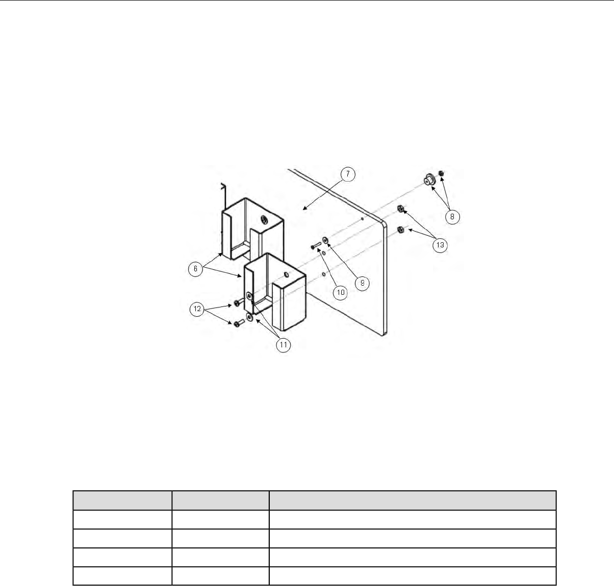
• Wrench, 11/32”
1. The two holes at the top of the mounting panel are for the collars that will enable the panel to slide
down into the extrusions. Assemble a collar by placing the small end of the collar against the back of
the mounting panel.
2. Insert the screw through a washer and the hole in the panel, then into the collar. Tighten the screw
all the way. Repeat with the other collar.
3. The eight holes in the middle of the mounting panel are for the power supply brackets. Mount a power
supply bracket to the panel by lining up the holes. Refer to the figure below for the correct positioning
of the bracket.
Figure 108: Mounting the Power Supply Bracket
4. Insert a screw through a washer and a hole in the bracket and the panel. Tighten with a nut.
5. Repeat for the other holes in the bracket.
6. Repeat the last three steps for the remaining brackets
Charger Wall Mount, Multiple Chargers: Fastening the Collars to a Charger
Parts List:
DescriptionQuantityItem #
Collar (611065)1614
Spring, Metric, 6.00x0.60x9.50 long (681006)415
Screw, M3x0.5x16 Phillips pan head (680128)416
Collar placement tool117
You will need:
• Screw driver, #2 Phillips
1. Locate the collar placement tool on the back of the charger so that it is against the charger’s end cap.
2. Position one of the collars against the collar placement tool. Place the collar directly over one of the
charger’s threaded channels.
Confidential: For informational use by Vocollect Resellers and customers only
156 | Vocollect Hardware Documentation
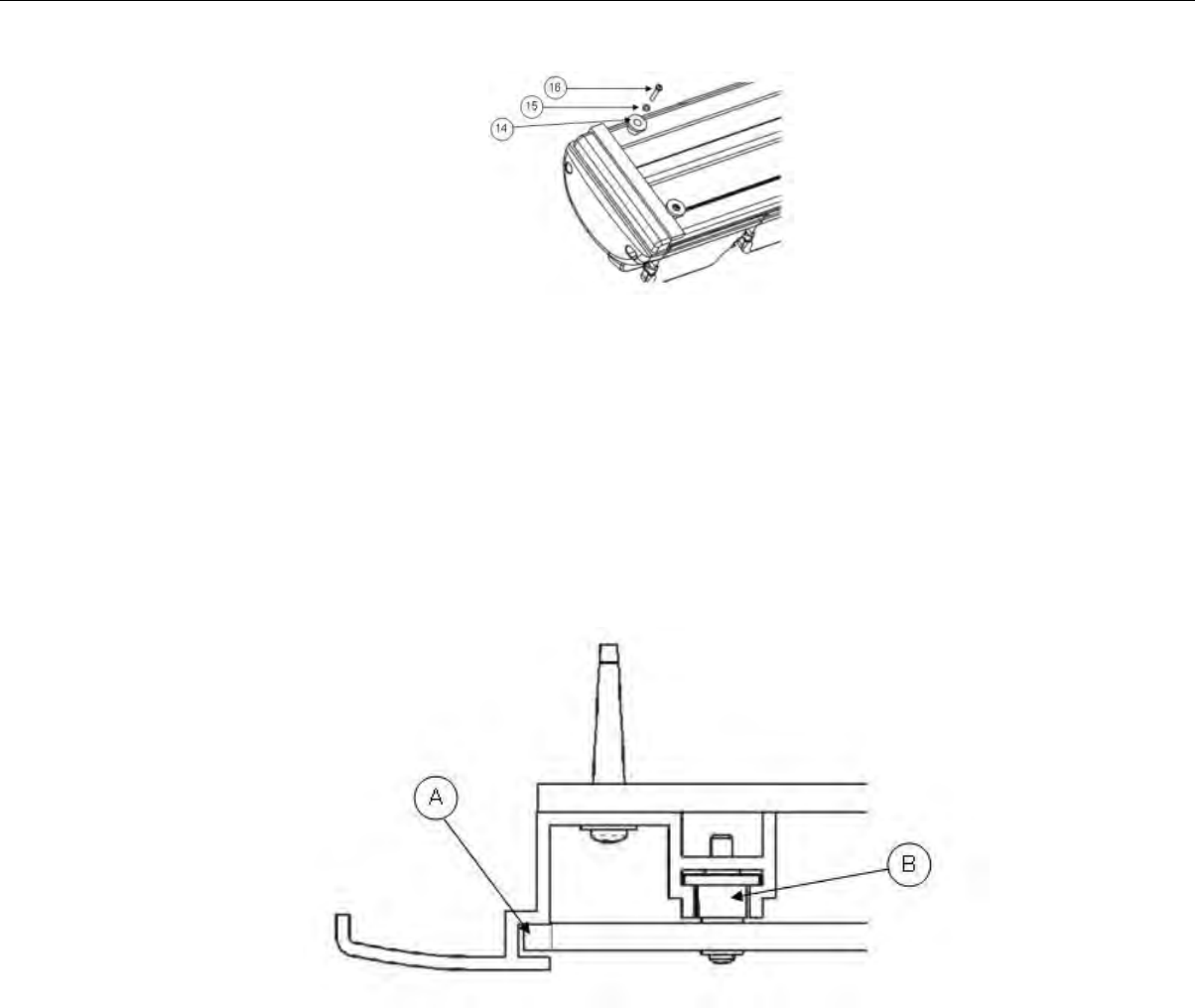
Figure 109: Fastening the Collars
3. Insert a spring into the collar, then secure with a screw. The screw should bottom out in the channel.
4. Repeat these steps for the rest of the collars.
Charger Wall Mount, Multiple Chargers: Completing the Assembly
At this point, you are ready to put the power supply mounting panel, the chargers, and the dry-erase
board sections into the extrusions. Insert the different pieces into the top of the extrusions and then
slide them down the extrusions.
1. Place the bottom of the mounting panel (the end without the collars) into the slots in the outer edges
of the extrusions.
Figure 110: Placing the Bottom of the Mounting Panel into the Slots
2. Slide the panel all the way down to the bottom of the extrusions. Make sure that the collars on the
top of the panel go into the extrusions’ T-channels as the panel is slid down. The panel will stop when
the collars are resting on the screws in the bottom of the T-channels.
3. Insert the first charger into the extrusions so that the battery release buttons are at the top. Place
the two bottom collars on the back of the charger into the T-channels in the extrusions.
Confidential: For informational use by Vocollect Resellers and customers only
Chargers | 157
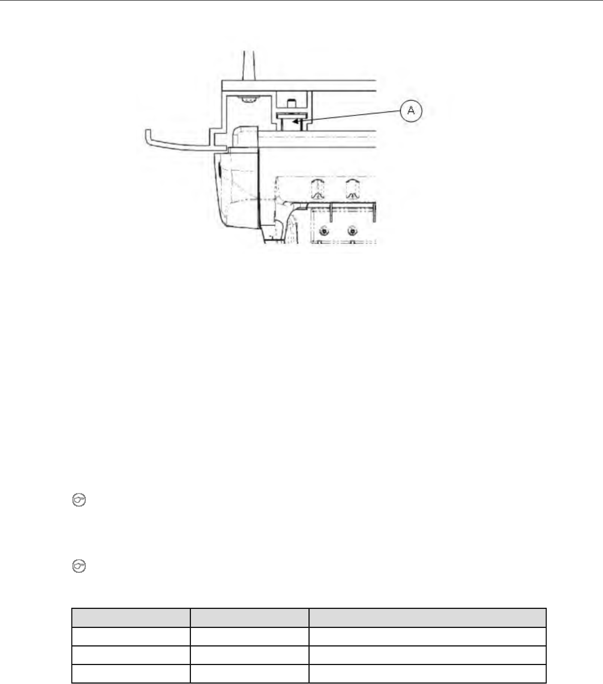
Figure 111: Placing the Bottom Collars into the T-Channels
4. Slide the charger down until it is resting on top of the power supply mounting panel. Make sure that
the two top collars on the back of the charger go into the T-channels as the charger is slid down.
5. Insert a section of dry-erase board into the extrusions and slide it down to the top of the charger. A
section of dry-erase board must be placed above each device charger.
6. Repeat the last three steps for the remaining chargers and dry-erase board sections.
About LED Indicators
Vocollect Talkman devices, SRX and SRX2 headsets, and their chargers have LEDs that indicate the
state of the equipment. These LEDs may be on, off or blink. In some cases an LED will blink, alternating
between two colors.
If the LEDs indicate that there is a problem, refer to information on troubleshooting to solve the problem.
See also Troubleshooting Problems Indicated by LED.
T2 and T2x Device Charger LED Indicators
Note: The indicators described here only indicate the status of the battery. They do not reflect the
state of the device.
It may take five to 10 seconds for the indicators to accurately report the battery conditions. Allow
some time for the indicators to become stable before making decisions based on the LED indicators.
Note: If there is no device in the charger or if the device in the charger does not have a battery and
one of these conditions occurs, disconnect the charger from its power source for about five seconds,
then reconnect the charger. If the condition persists, return the charger for service.
If a device with a battery is the charger...Right Indicator ColorLeft Indicator Color
Troubleshoot the problemOffOff
The battery is charged and ready to use.GreenOff
The battery is being charged.OffRed
Confidential: For informational use by Vocollect Resellers and customers only
158 | Vocollect Hardware Documentation
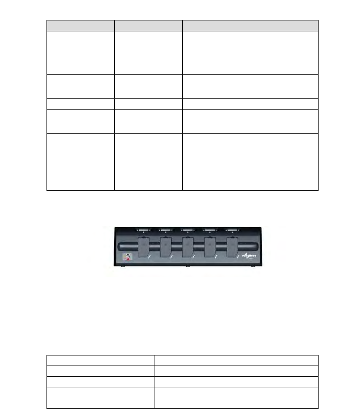
If a device with a battery is the charger...Right Indicator ColorLeft Indicator Color
The battery may not be inserted into the charger
correctly.
If the LED continues to blink red after inserting
the battery into the charger correctly, troubleshoot
the charger.
OffBlinking Red
The battery is defective. Remove the battery from
the charger and give it to your system
administrator.
Blinking Green, then OffBlinking Red, then Off
Troubleshoot the problemOffBlinking Yellow
This will occur briefly when a battery is removed
from the charger. If the LEDs stay on for a length
of time, troubleshoot the problem.
GreenYellow
The battery may not be properly inserted into the
charger.
OffYellow
The battery may be too hot or too cold. Wait for the
battery's temperature to normalize.
If the yellow LED remains lit for more than two
hours, troubleshoot the problem.
T1 10-Bay Combination Charger
Figure 112: T1 10-Bay Combination Charger
• The T1 10-Bay Combination Charger can store five devices at a time.
• The charger can store and charge ten batteries at a time - five batteries in the lower battery slots
and five batteries connected to devices in the upper device slots.
• A T1 device should not be placed into a device charger without a battery attached to it.
• The socket-outlet should be installed near the equipment and should be easily accessible.
T1 10-Bay Combination Charger Specifications
21.9" (55.6 cm)Length
3.7" (9.4 cm)Depth
5.9" (15 cm)Height
Input Voltage: 12 V DC
Input Current: 5 A maximum
Power
Confidential: For informational use by Vocollect Resellers and customers only
Chargers | 159
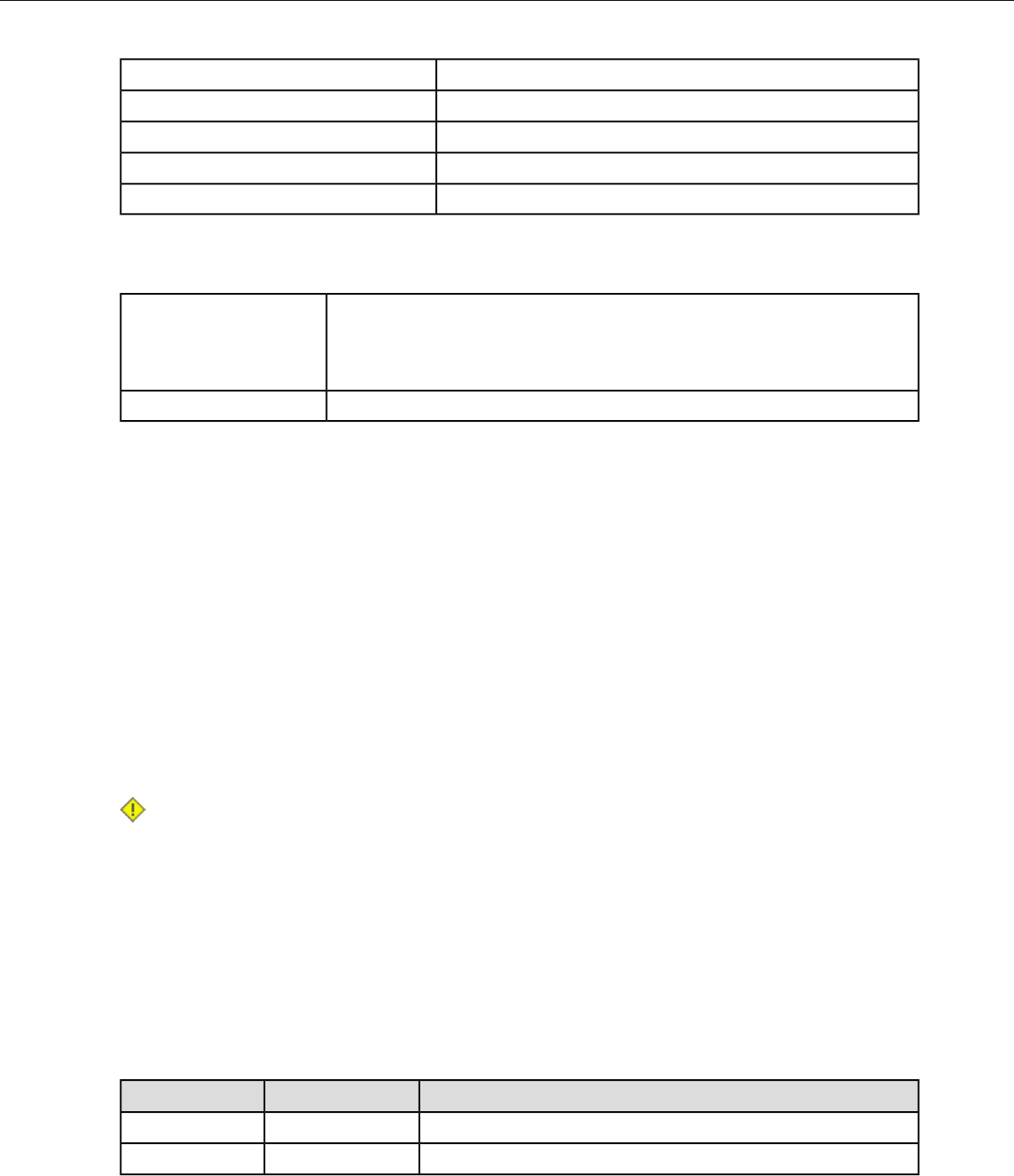
70.5 ounces (2000 g)Weight
Uses standard IEC 60320 plugCord
32° to 122° F (0° to 50° C)Operating Temperature
-40° to 158° F (-40° to 70° C)Storage Temperature
95% non-condensingHumidity
T1 10-Bay Combination Charger Power Supply Specifications
Input Voltage: 100-240 Vac
Input Current: 2.4 A
Input
Line Frequency: 50-60 Hz
Output: 80 W (12 V DCx 6.67 A)Output
T1 10-Bay Combination Charger Wall Mount
This unit provides a convenient surface for mounting five charger units and their associated power
supplies on a wall. Customer assembly required.
•Vocollect recommends that the charger have a minimum of 12 inches of clearance above it for placement
and removal of the devices. Do not install another charger directly on top.
• The lowest anchor for each extrusion must be a minimum of 12 inches from the floor.
• Vocollect recommends using #8 pan head sheet metal screws of appropriate length into the center of
the wall studs. The clearance between the bottom of the screw head and mounting surface should be
approximately 3/16 of an inch.
• Install the battery charger so that the supporting surface and installation will safely support the
weight of a fully loaded charger, greater than 8 pounds.
• If wall stud mounting is impractical, Vocollect recommends using wall anchors that are capable of
supporting at least 10 lbs/anchor.
• The installer must verify the charger is removable from the wall without use of a tool.
Caution:
• Injury to persons and damage to the wall may result if the charger or mounting hardware is
pulled from the wall. To reduce the likelihood of such an injury, mount only on a surface that is
structurally sound.
• Customer assumes all responsibility for the installation of these units.
• Be aware of potential hazards (electrical wires, waterlines, etc.) when drilling the pilot holes.
• Avoid blocking power outlets and other wall receptacles when installing the extrusions and
charger unit.
Installing the T1 10-Bay Combination Charger Wall Mount
The following parts come with the T1 10-Bay Combination Charger Wall Mount:
DescriptionQuantityItem #
Charger Stand11
Phillips screws22
Confidential: For informational use by Vocollect Resellers and customers only
160 | Vocollect Hardware Documentation

DescriptionQuantityItem #
Rubber feet23
Extrusion24
Self-drilling screw anchor #885
Washer, #8, flat, type B regular86
Screw, #8x1.5 Phillips pan head87
Screw, #10-24x.312 hex, socket head28
Drilling template sheet19
You will need the following equipment:
• Drill with 1/8” bit
• Screw driver, #2 Phillips
• Allen key, Hex 1/8”
1. Secure the rubber feet to the stand using the Phillips screws.
2. Position the stand so that its top lip is inserted into the center channel in the back of the charger.
3. Secure each stand to the charger by inserting Phillips screws through the holes in the stand and
screwing them into the slot on the bottom of the charger.
4. Using the drilling template, mark the eight holes for the anchors. The bottom anchor holes must be
at least 12 inches from the floor.
5. Drill the pilot holes for the anchors, and install the battery charger with wall anchors or screws on
16” centers.
6. Place one of the extrusions against the wall and align its holes with the installed anchors. The
extrusions have a specific inside and outside edge and must be placed onto the wall correctly. The
inside edge of the extrusion has the T-channel into which the chargers are inserted.
7. Insert a screw through a washer and the hole in the extrusion, then into the anchor. Tighten the
screw to hold the extrusion in place. Repeat this step with the other screws and washers.
8. Repeat the previous two steps for the other extrusion.
9. Make sure that the extrusions are vertical and then secure them by tightening the screws all the
way.
10. Locate the small hole in the bottom of the T-channel on the inside edge of each extrusion. Insert one
of the socket head screws (item 5) into both of the bottom holes and tighten them all the way.
Confidential: For informational use by Vocollect Resellers and customers only
Chargers | 161
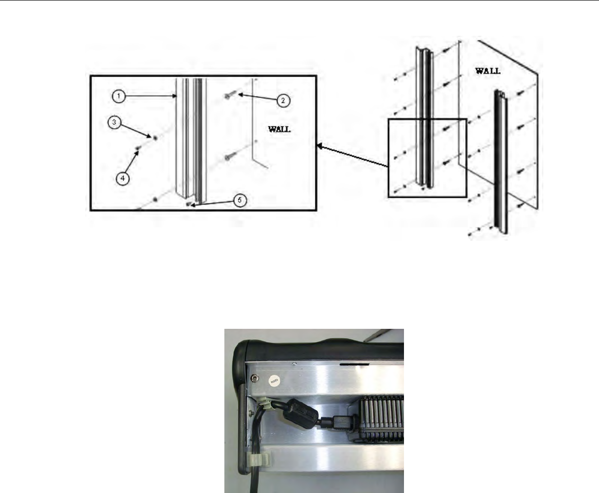
Figure 113: Mounting the Extrusions
Connecting the Power Supply to the T5/A500 Combination Charger
1. Connect the AC cord to the left end of the power supply that is mounted inside the charger.
2. Route the cable through the plastic clips as shown.
Figure 114: Cable Routed Through Plastic Clips
3. Push the clips to lock the cord in place.
Confidential: For informational use by Vocollect Resellers and customers only
162 | Vocollect Hardware Documentation
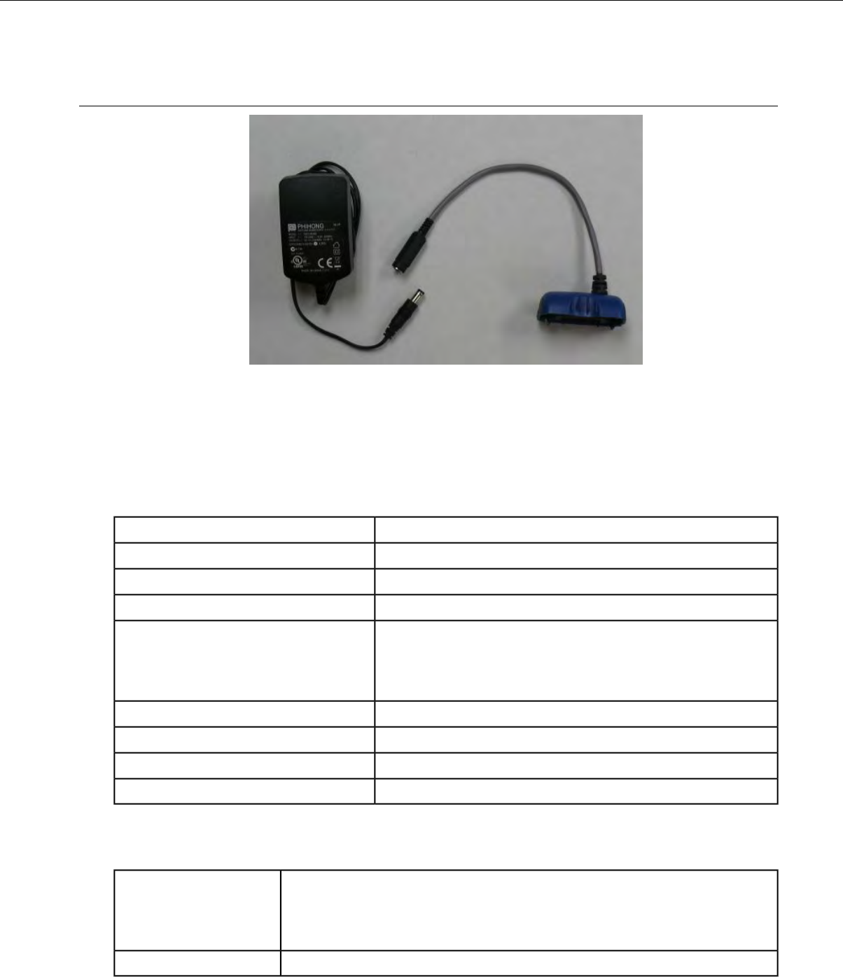
T1 Single Charger Cable
Figure 115: T1 Single Charger Cable
• The T1 Single Charger Cable allows you to use a commercially available 5V charger to charge a single
T1 battery within a T1 device.
• Do not remove the battery from the device when connecting the device to the charger cable.
T1 Single Charger Cable Specifications
21.21" (53.9 cm)Length
6.64" (16.9 cm)Depth
6.89" (17.5 cm)Depth with Wall Bracket
6.12" (15.5 cm)Height
Input Voltage: 100-250 Vac
Input Current: 2.4 A maximum
Power
Line Frequency: 50-60 Hz
Uses standard IEC 60320 plugCord
50° to 140° F (10° to 40° C)Operating Temperature
-22° to 158° F (-30° to 70° C)Storage Temperature
Functional to 90% non-condensingHumidity
T1 Single Charger Cable Power Supply Specifications
Input Voltage: 100-240 Vac
Input Current: 0.5 A
Input
Line Frequency: 50-60 Hz
Output: 10 W (5 V DCx 2.0 A maximum)Output
Confidential: For informational use by Vocollect Resellers and customers only
Chargers | 163
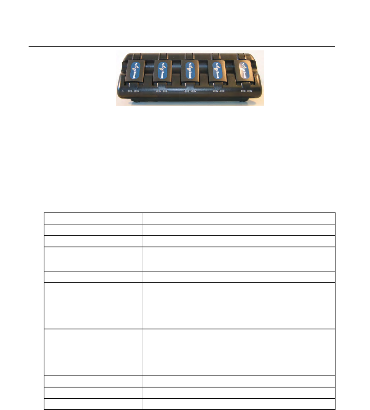
SRX Headset Battery Charger
Figure 116: SRX Headset Battery Charger
• The SRX battery charger is available in a five-bay model with five battery slots and a single battery
charger with one battery slot.
• To power on the charger, connect the power supply to the charger and a power source. The LED
indicator in the left corner of the charger is green when the charger is receiving power.
• SRX headset battery chargers are designed to be placed on a desktop or mounted on a wall using a
wall mount kit.
SRX Headset Battery Charger Specifications
Specifications for the 5-Bay Charger
Approximately 31 cm (12")Width
Approximately 10 cm (4")Depth
Approximately 10 cm (4")Height
Input voltage: 5VDC
Input current: 5A
Input
25 WOutput
UL listed and CSA certified
Three conductor 18 AWG
Cord: US, Mexico, Canada
Terminated with a molded-on plug cap rated at 125V 10A minimum
Six feet minimum length
H05VVF3G1.00 per CENELEC HD-21 marked <HAR>
Three conductor 1 mm2
Cord: Other Countries
Terminated with a molded-on plug cap rated at 125V 10A minimum
Six feet minimum length
50° to 140° F (10° to 40° C)Operating Temperature
-22° to 158° F (-30° to 70° C)Storage Temperature
Functional to 90% non-condensingHumidity
Confidential: For informational use by Vocollect Resellers and customers only
164 | Vocollect Hardware Documentation

Specifications for the Single-Bay Charger
Approximately 8 cm (3")Width
Approximately 11 cm (5")Depth
Approximately 6 cm (2.5")Height
Input voltage: 100-240 VAC
Input current: 0.9 A maximum
Input
Line frequency: 50-60 Hz
5 WOutput
UL listed and CSA certified
Three conductor 18 AWG
Cord: US, Mexico, Canada
Terminated with a molded-on plug cap rated at 125V 10A minimum
Six feet minimum length
H05VVF3G1.00 per CENELEC HD-21 marked <HAR>
Three conductor 1 mm2
Cord: Other Countries
Terminated with a molded-on plug cap rated at 125V 10A minimum
Six feet minimum length
50° to 113° F (10° to 45° C)Operating Temperature
-22° to 158° F (-30° to 70° C)Storage Temperature
Functional to 90% non-condensingHumidity
SRX Battery Charger Wall Mount
This unit provides a convenient surface for mounting the SRX battery charger and its associated power
supply on a wall.
• Customer assembly required.
• Customer assumes all responsibility for the installation of these units.
• Avoid potential hazards (electrical wires, waterlines, and similar building components) when drilling
into the wall.
• Avoid blocking power outlets and other wall receptacles when installing the charger.
• Anchoring a wall mount to a wall stud generally results in a more stable installation. If you drill into
a wall stud, do not use a screw anchor in that hole.
• Anchors must be at least 12 in. (30.48 cm.) from the floor to allow for proper attachment, seating,
and removal of the charger unit.
SRX Battery Charger Wall Mount: Mounting the SRX Single-Bay Battery Charger
Vocollect recommends storing the single-bay charger on a desktop, but it can also be mounted on a wall.
Important: In order to mount the single-bay charger on a wall, the stand on the bottom of the
charger must be reversed.
1. Turn the charger over and loosen the screw on the bottom of the stand.
2. Flip the stand over and reinstall the screw.
Confidential: For informational use by Vocollect Resellers and customers only
Chargers | 165
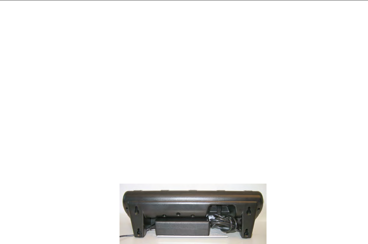
3. Drill two pilot holes for wall anchors (not included). The anchors should be spaced 2.75" apart vertically.
4. Install the anchors and screws (not included).
5. Be sure to use both the keyhole slot and screw slot to hang the charger.
SRX Battery Charger Wall Mount: Mounting the SRX 5-Bay Battery Charger
Parts List:
• 4 self-drilling screw anchors #8
• 4 screws, #8 x 1.5 Phillips pan head
You will need:
• Drill with 1/8” bit
• Screw driver, #2 Phillips
1. Mark the location of the anchor holes on the wall, spaced 9" apart horizontally and 2" apart vertically.
Make sure that the bottom anchor holes are at least 12 inches from the floor and level.
2. Drill the pilot holes for the anchors, insert anchors and screws. Leave screw heads sticking out from
the wall.
3. Insert the power supply into the back of the charger as shown. Plug the power supply into the charger
but do not plug it into a power source until after mounting is complete.
Figure 117: Power Supply Plugged into Charger
4. Hang the charger on the screws by lining up the keyhole slots on the back of the charger with the
screw heads on the wall.
Confidential: For informational use by Vocollect Resellers and customers only
166 | Vocollect Hardware Documentation
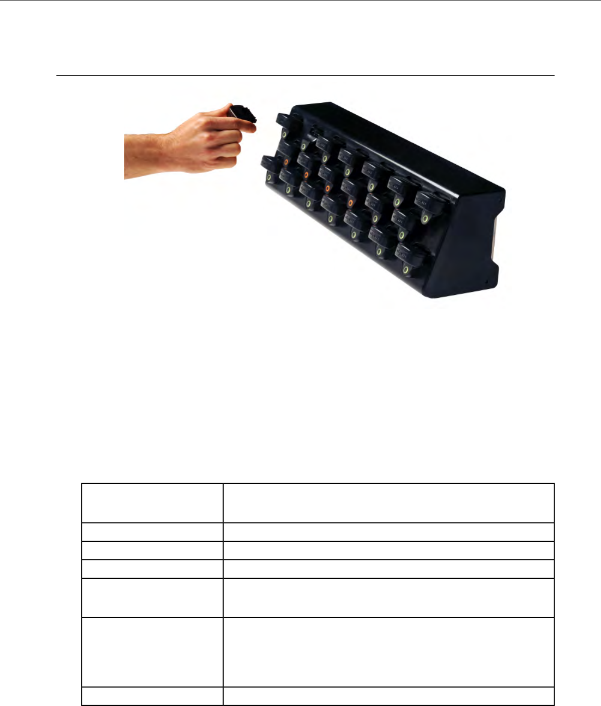
SRX2 Headset Battery Charger
Figure 118: SRX2 20-Bay Headset Battery Charger
• The SRX2 battery charger has 20 ports to charge up to 20 batteries at one time.
• The LED indicator light on the charger front panel indicates if the charger is powered on or not.
• Each battery port has LED lights that indicate battery charge status and battery health.
• SRX2 headset battery chargers are designed to be placed on a desktop or mounted on a wall using a
DIN rail. Customer with multiple chargers must allow the required space between wall mounted
units and must avoid stacking desktop units on top of each other.
SRX2 Headset Battery Charger Specifications
Specifications for the 20-Bay Charger
8 lbs. (3.63 kg.) with 20 batteries
6.38 lbs. (2.89 kg.) without batteries
Weight
Approximately 55 cm (21.65 in.)Width
Approximately 15.8 cm (6.22 in.)Depth
Approximately 15.7 cm (6.18 in.)Height
Power supply input voltage: 90VAC to 264VAC, 50/60Hz
Power supply input current: 2A max
Input
Power supply output voltage: 12V
Power supply output power: 80W max
Output
Less than 40W required to charge 20 batteries from fully depleted to
fully charged.
Uses standard IEC 60320 plugCord
Confidential: For informational use by Vocollect Resellers and customers only
Chargers | 167
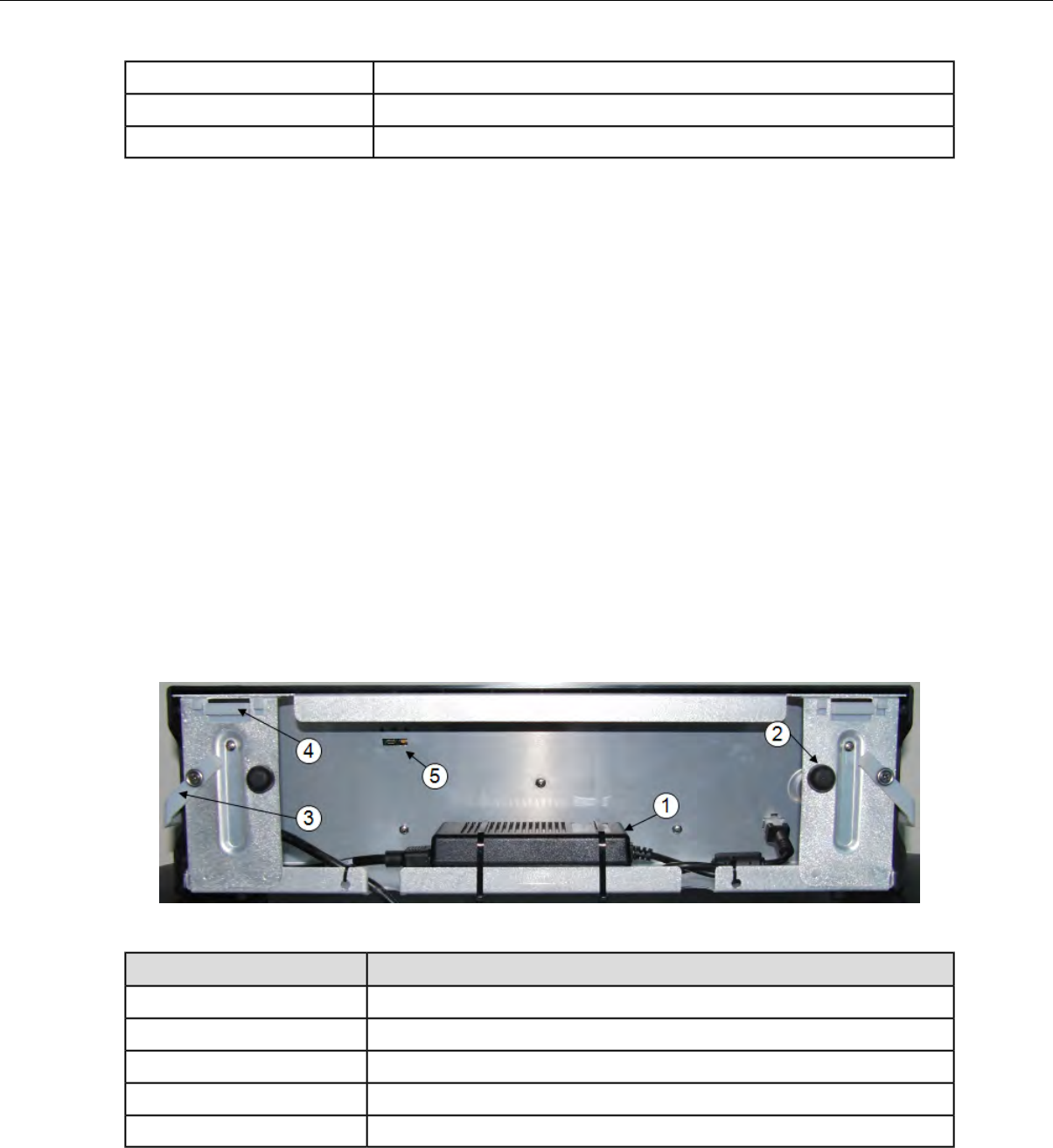
32° to 104° F (0° to 40° C)Operating Temperature
-40°F to 158°F (-40° to 70°C)Storage Temperature
5% - 95% relative humidity, non-condensingHumidity
SRX2 Battery Charger Wall Mount
The SRX2 battery charger is ready for mounting on a standard DIN rail without any customer
modifications. A DIN rail must be installed on a wall in a suitable location. Vocollect offers a DIN rail
suitable for mounting a single charger, but customers may choose to purchase rails from other suppliers
as long as the rails meet Vocollect specifications. Consider the following before wall mounting your
charger.
• Customer assembly required for the rail wall mount.
• Customer assumes all responsibility for the installation of charger units.
• Installer must verify that the installation meets all local building codes.
• Avoid potential hazards (electrical wires, waterlines, and similar building components) when drilling
into the wall.
• Avoid blocking power outlets and other wall receptacles when installing the rail and charger.
• Anchoring a wall mount rail to a wall stud generally results in a more stable installation. If you drill
into a wall stud, do not use a screw anchor in that hole.
• If you are mounting two chargers side by side, you must leave at least 1 in. (2.54 cm.) of space between
the two units to allow clearance for the locking arms.
• Rails must be anchored to the wall at least 12 in. (30.5 cm.) from the floor to allow for proper
attachment, seating, and removal of the charger unit.
• If you are mounting a charger directly above another charger, Vocollect recommends clearance of at
least 10 in. (25.4 cm.) between DIN rails.
Figure 119: SRX2 charger - back view
DescriptionPart Number in Diagram
power supply
1
rubber stop for leveling charger against wall
2
locking arm for securing charger to DIN rail
3
mounting hook for hanging charger on DIN rail
4
USB port for charger software upgrades
5
Mounting the SRX2 20-Bay Battery Charger
You will need:
Confidential: For informational use by Vocollect Resellers and customers only
168 | Vocollect Hardware Documentation
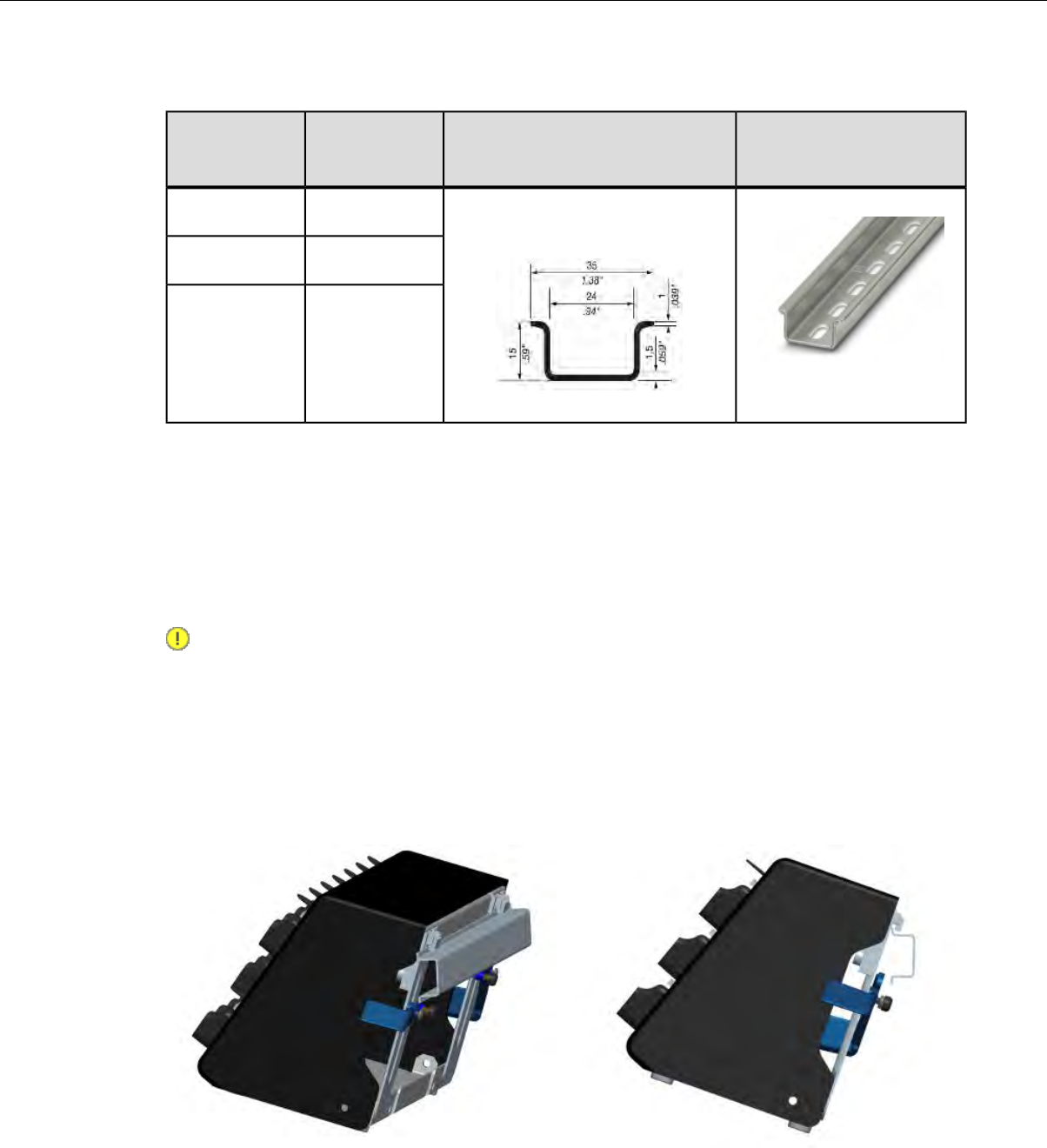
• DIN rail, slotted steel 35 mm X 15 mm, Vocollect Part #CM-1000-20-1 or customer-supplied DIN rail
meeting the following specifications
Standard DIN railDIN rail specsMinimum cut
lengths for
rail
Number of
chargers on
rail
Single unit length 550 mm; weight
331.5 g (11.6933 oz)
550 mm1
1101 mm2
1652 mm3
• Drill
• Fasteners
• Screw driver
1. Install the DIN rail on the wall in the desired location. Ensure that the secure installation, supporting
surface, and mounting hardware will safely support the weight of a fully loaded charger, at 25 lbs.
per linear foot (37.2 kg/m) of DIN rail. Ensure that the anchor holes are at least 12 inches (30.5 cm.)
from the floor. Verify that the installation meets all local building codes.
2. Important: The power supply for the charger should already be zip-tied in the back of the charger
chassis. If it is not, plug the power supply into the charger and secure it. Do not plug it into a
power source until after mounting is complete.
Before attaching the charger to the rail, open the locking arms on the back of the unit by rotating the
two levers out on each side of the charger. The arms are parallel to the floor in the unlocked position.
3. Attach the charger to the DIN rail by hanging the two hooks on the back of the unit on the top lip of
the rail.
Attaching the SRX2 Charger to a DIN Rail
4. Slide the charger horizontally to the desired position on the rail, and rotate the locking arms into the
locked position - flush with both sides of the unit.
Confidential: For informational use by Vocollect Resellers and customers only
Chargers | 169
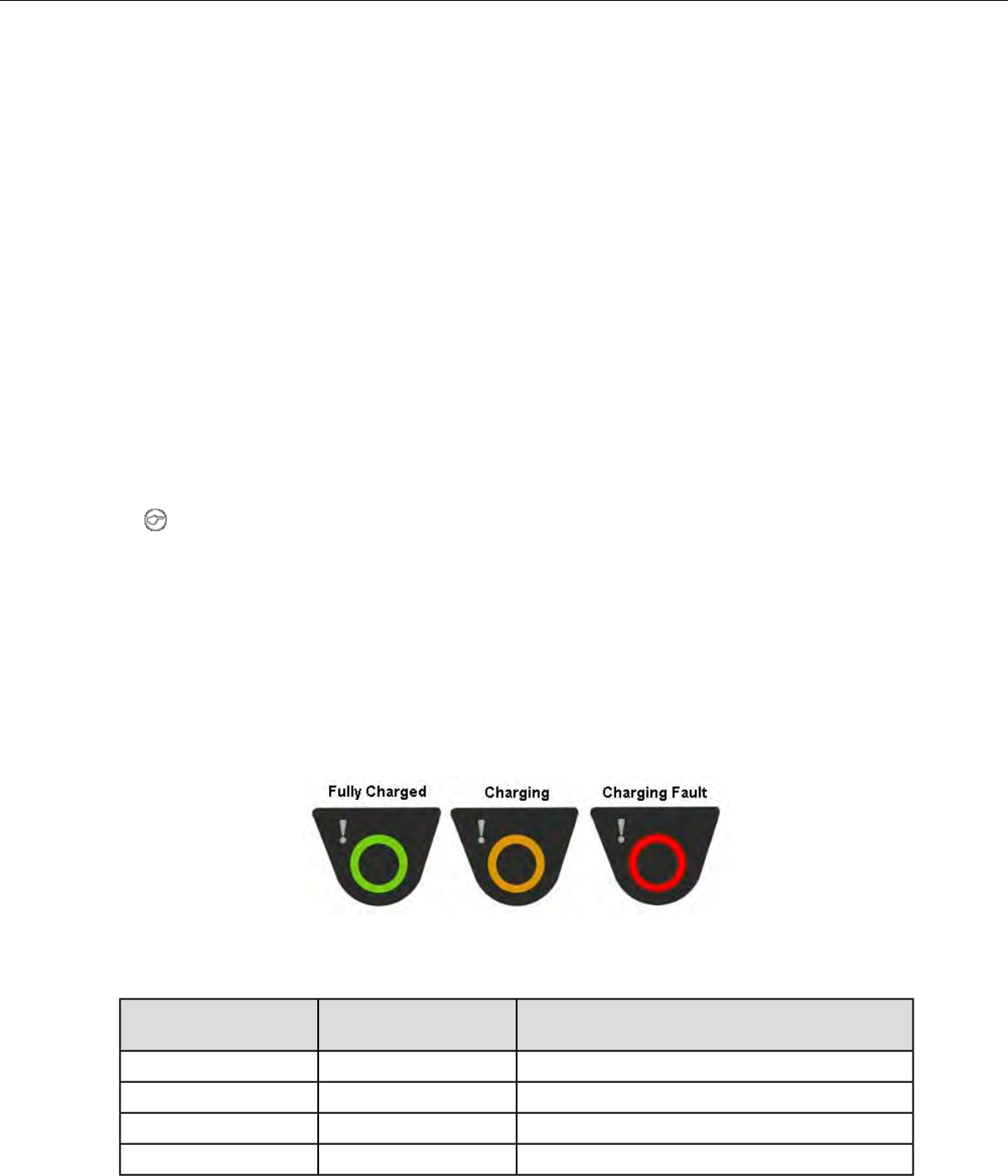
5. If the charger does not feel secure on the rail, adjust the rubber stops on the back of the unit by
screwing them out toward the wall.
6. Plug the power supply into a power source and check the LED indicator at the bottom right of the
charger face. If the indicator light is a solid green, the charger is powered on.
About LED Indicators
Vocollect Talkman devices, SRX and SRX2 headsets, and their chargers have LEDs that indicate the
state of the equipment. These LEDs may be on, off or blink. In some cases an LED will blink, alternating
between two colors.
If the LEDs indicate that there is a problem, refer to information on troubleshooting to solve the problem.
See also Troubleshooting Problems Indicated by LED.
SRX2 Battery Charger LED Indicators
The SRX2 battery charger has an LED indicator light, located at the bottom right of the charger face,
that signals the status of the charger.
• Solid green LED: Charger power is on
• No light: Charger power is off
• Solid red LED: Charger is experiencing a power fault
Note: If the charger LED indicator is red, unplug the charger power supply from the power
source, and remove all batteries. Plug the power supply into the power source again. If the LED
remains red, the charger may require repair or replacement.
Charger Port Indicators
Additionally, each battery port has two LED indicator lights that apply to the status of the resident
battery.srx
• The ring LED is a circular light that indicates the battery's charge status.
• The alert LED, in the shape of an exclamation point (!), indicates that there is a battery condition
requiring attention. When this indicator is on, the battery on that charger port may not last a full
shift. Check VoiceConsole for a specific alert message.
Figure 120: Battery Port Indicators
The following chart describes the patterns for the battery port LED indicator lights.
SRX2 Battery StatusAlert LED (Battery
Health)
Ring LED (Charge
Status)
Battery is fully chargedOffSolid Green
Battery is chargingOffSolid Yellow
Charging fault detectedOffBlinking Red
Battery alert condition; fully chargedSolid RedSolid Green
Confidential: For informational use by Vocollect Resellers and customers only
170 | Vocollect Hardware Documentation

SRX2 Battery StatusAlert LED (Battery
Health)
Ring LED (Charge
Status)
Battery alert condition; chargingSolid RedSolid Yellow
Battery alert condition; fault detectedSolid RedBlinking Red
Unknown batterySolid RedBlinking Red
Confidential: For informational use by Vocollect Resellers and customers only
Chargers | 171

Chapter 10
Bar Code Readers and Printers
Supported Devices
The Vocollect Voice system supports the use of several styles of bar code readers, including guns, scanners,
and wands. Vocollect extends support for the products listed below, but compatibility with Vocollect
Voice is not limited to these peripherals. Verify support for your device in the release notes for your
version of Vocollect Voice software or contact your Vocollect sales representative.
• Intermec SR30 Handheld Scanner
• Intermec SR61T Tethered Industrial Handheld Scanner
• Intermec SR61B Rugged Wireless Handheld Scanner
• Honeywell LXE 8651 and 8652 Wearable Ring Scanners
• Honeywell IS4225 Laser Scanner
• Honeywell MS9535 Voyager BT Scanner
• Symbol LS3408-FZ
• Symbol LS3408-ER
• Symbol LS4208
The bar code reader procedures described in this documentation are only for instances where the Vocollect
Voice software manipulates a supported scanner. See the documentation provided by the bar code
manufacturer for other bar code procedures.
Note: Notes:
• Devices must be configured to work with bar code readers. If a device has not been configured,
you must set the necessary parameters in the device's voice process software (VCF file) before
using a bar code reader with the device.
• Talkman devices generally support only decoded bar code wands and guns.
• The Intermec SF51 cordless scanner is compatible with some workarounds.
• Talkman devices will support the Symbol RS 1 Ring Scanner (a non-decoded device) but only
when used with an external decode block.
• Vocollect Voice supports bar code readers that are built into a supported handheld device. If you
are prompted by the voice engine to scan a bar code, use the built-in bar code reader as the device
manufacturer recommends. See the documentation provided by the device manufacturer.
• Connect the bar code reader to the device before scanning a bar code. Bar code readers have a
connector with a blue bend relief. The connector end of the bar code reader is attached to the blue
port on the device.
• You can scan bar codes only when you are prompted for bar code information.
Supported Printers
Vocollect Voice supports the printers listed in the release notes for your version of Vocollect Voice.
Vocollect extends support for the printers listed below, but compatibility with Vocollect Voice may not
be limited to these peripherals. If you are prompted by the voice engine to print, use the supported
printer as the device manufacturer recommends. See the documentation provided by the device
manufacturer.
• Intermec PB50 Rugged Mobile Label Printer
• Intermec PM4i Mid-Range Printer
• Zebra QL Series
Confidential: For informational use by Vocollect Resellers and customers only

The printer procedures described in this documentation are only for instances where the Vocollect Voice
software manipulates a supported printer. See the documentation provided by the printer manufacturer
for other printer procedures.
Note: Devices must be configured to work with printers. If a device has not been configured, you
must set the necessary parameters in the device's voice process software (VCF file) before using a
printer with the device. Connect or pair the printer to the device before printing.
Intermec SF51 Cordless Scanner
Figure 121: Intermec®SF51 Cordless Scanner
• Always take hold of the bar code scanner by its handle.
• When not in use, the bar code scanner should be secured.
• For detailed specifications for this product, visit Intermec’s website.
Pairing the Intermec SF51 Scanner: Device Is the Initiator
During use, it is possible for the scanner to disconnect from the device if the communication link is
disrupted. When the scanner is setup so that the device initiates the connection, the device typically
recovers the connection automatically. When the scanner initiates the connection, it typically requires
the press of a button to activate and recover the connection.
This method of pairing is useful if a single device will always be associated with one scanner.
You must have access to VoiceConsole to set up the pairing. For production use, Vocollect recommends
that you create a specific device profile in VoiceConsole to store many of the following settings.
1. View the properties of the device, and ensure that Bluetooth is enabled. If it is not enabled, click Edit
this device and set Bluetooth Enabled to "enabled."
2. Select the Pair this device with a peripheral option.
3. For Pairing Type select "Bluetooth Scanner."
4. For Connection Mode select "Device initaties connection with peripheral."
5. In the Bluetooth Address enter the Bluetooth MAC address of the scanner. This 12-character ID
is labeled "MAC ID" and is found on the side of the battery unit of the scanner.
6. For Security select "Enabled."
7. For Security Key enter four zeros "0000."
8. Using VoiceConsole, locate the specific device to be paired with the scanner.
9. Click Pair with peripheral to initiate pairing.
Confidential: For informational use by Vocollect Resellers and customers only
174 | Vocollect Hardware Documentation

Pairing the Intermec SF51 Scanner: Scanner Is the Initiator
During use, it is possible for the scanner to disconnect from the device if the communication link is
disrupted. When the scanner is setup so that the device initiates the connection, the device typically
recovers the connection automatically. When the scanner initiates the connection, it typically requires
the press of a button to activate and recover the connection.
This method of pairing is useful if a scanner will be used with more than one device.
You must have access to VoiceConsole to set up the pairing. For production use, Vocollect recommends
that you create a specific device profile in VoiceConsole to store many of the following settings.
1. Using the EasySet Tool from Intermec and the Bluetooth address of the device to be paired, generate
a barcode.
a) If the device does not have a barcode label, generate the FNC3 on a PC with a full keyboard and
number pad. Hold the ALT key down and press the four-number sequence "1 0 7 9" on the number
pad. A small number 3 will appear to indicate the presence of the code. Some barcode software
packages have special insertion keystrokes for FNC3.
b) Find the Bluetooth MAC address of the device on the rear of the device near the belt clip. The
address begins with "BT."
2. Scan the barcode onscreen or print the barcode and scan it with the Intermec SF51 ring scanner.
3. Using VoiceConsole, locate the specific device to be paired with the scanner.
4. View the properties of the device, and ensure that Bluetooth is enabled. If it is not enabled, click Edit
this device and set Bluetooth Enabled to "enabled."
5. Select the Pair this device with a peripheral option.
6. For Pairing Type select "Bluetooth Scanner."
7. For Connection Mode select "Device listens for peripheral connection."
The scanner is paired when its blue LED stops flashing.
8. For Security select "Enabled."
9. For Security Key enter four zeros "0000."
10. Click Pair with peripheral to initiate pairing.
11. To complete the pairing, scan the barcode created for the device in the first step.
12. When finished using the device and scanner, unpair the device by scanning the following barcode to
set the scanner to slave mode. See Clearing a pairing of an Intermec SF51 Cordless Scanner.
Note: Performing this step ensures that the scanner does not generate spurious Bluetooth RF
that could interfere with other transmissions.
Clearing a Pairing of an Intermec SF51 Cordless Scanner
When finished using the device and scanner for the day it is advisable to unpair the device from the
scanner by setting the scanner to slave mode. Performing this step assures the scanner does not generate
spurious Bluetooth RF that could potentially interfere with other radio transmissions including 802.11/RF
network traffic.
Scan the following barcode:
Confidential: For informational use by Vocollect Resellers and customers only
Bar Code Readers and Printers | 175
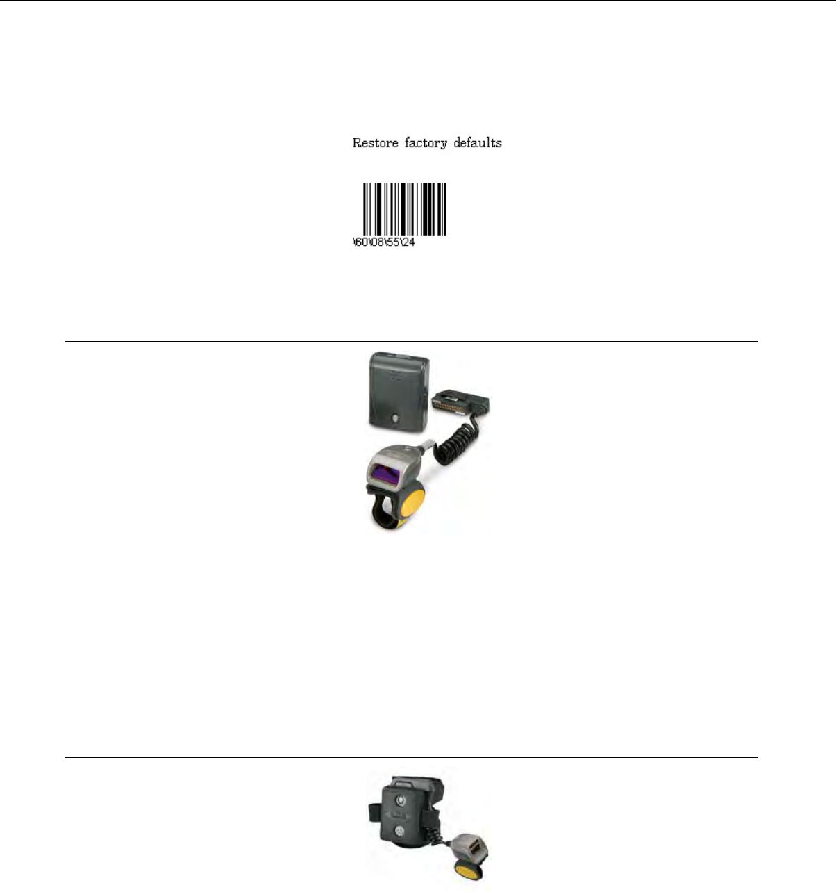
Restore Factory Defaults of an Intermec SF51 Cordless Scanner
Scan the following barcode:
Honeywell LXE 8651 Bluetooth Ring Scanner
Figure 122: Honeywell LXE Ring Scanner 8651 Wearable Bluetooth Scanner
• Supported with Honeywell LXE HX2 wearable devices only.
• The scanner is capable of decoding 1D barcodes.
• For detailed specifications for this product, visit the Honeywell website.
• The Bluetooth scanner should not add any characters to the end of a barcode scan. Setting the
Bluetooth ring scanner to its default will ensure this behavior. Please see Honeywell LXE's Bluetooth
Ring Scanner Guide for instructions on setting the scanner to its default.
Honeywell LXE 8652 Bluetooth Ring Scanner
Figure 123: Honeywell LXE 8562 Ring Scanner
• All Talkman T5 Series devices support the LXE®8562 scanner.
• The scanner is capable of decoding 2D barcodes.
Confidential: For informational use by Vocollect Resellers and customers only
176 | Vocollect Hardware Documentation

• Bluetooth™wireless technology is used to connect the Honeywell LXE 8652 to a device. During use,
it is possible for the scanner to disconnect from the device if the communication link is disrupted.
When the scanner is setup so that the device initiates the connection, the device typically recovers
the connection automatically. When the scanner initiates the connection, it typically requires the
press of a button to activate and recover the connection.
• The large black unit contains the Bluetooth™radio and battery. The battery must be removed for
charging.
• For detailed features and specifications of the Honeywell LXE 8652 ring scanner, please refer to the
manufacturer's website.
Honeywell LXE 8652 Bluetooth Ring Scanner Parts
Vocollect Part NumberRing Scanner Part
BC-613-1Barcode Scanner, Bluetooth Ring (Honeywell LXE 8652) Kit (scanner
with Bluetooth module, battery, and two wrist straps - large and small)
BC-613-101Replacement scanner without Bluetooth module (Honeywell LXE 8652)
BC-613-102Replacement battery, Bluetooth Ring Scanner (Honeywell LXE 8652)
BC-613-103Replacement large hand wrist strap, barcode scanner, Bluetooth Ring
(Honeywell LXE 8652)
BC-613-104Replacement small hand wrist strap, barcode scanner, Bluetooth Ring
(Honeywell LXE 8652)
BC-613-105Replacement 8-bay battery charger (Honeywell LXE 8652)
BC-613-106Replacement single battery charger (Honeywell LXE 8652)
BC-613-107Replacement finger strap (20 pack), barcode scanner, Bluetooth Ring
(Honeywell LXE 8652)
BC-613-108Replacement finger strap assembly (20 pack), barcode scanner,
Bluetooth Ring (Honeywell LXE 8652)
BC-613-109US power cord cable
BC-613-110Euro power cord cable
BC-613-111British power cord cable
Setting up the Honeywell LXE 8652 Scanner
The Honeywell LXE 8652 scanner only acknowledges the first “reset” barcode with an audible tone.
Subsequence barcodes used for setup are silently acknowledged as successful when the scan beam
extinguishes.
The scanner should be approximately 1 foot from the page with the centered red cross almost filling the
barcode for the setup scans to be successful.
1. Print this page.
2. Scan the following code to ensure that the scanner's parameters are set to the default settings.
Confidential: For informational use by Vocollect Resellers and customers only
Bar Code Readers and Printers | 177

Figure 124: Set Factory Defaults
3. Scan the following bar code to set the reconnect timeout to OFF.
Figure 125: Set Reconnect Timeout to Off
4. Configure scan suffix 1 as carriage return (0x0D). Scan the following bar code to set scan suffix 1.
TermChar1 (suffix 1) = 1013 = 0x0D = Carriage Return
Figure 126: Set Scan Suffix 1
5. Scan the following four bar codes to enter the character information.
1
0
1
Confidential: For informational use by Vocollect Resellers and customers only
178 | Vocollect Hardware Documentation

3
6. Scan the following bar code to program terminating character 2 (suffix 2).
TermChar2 (suffix 2) = 1010 = 0x0A = Line Feed
Figure 127: Set Scan Suffix 2
7. Scan the following bar codes to enter the character information.
1
0
1
Confidential: For informational use by Vocollect Resellers and customers only
Bar Code Readers and Printers | 179

0
8. Scan the following bar code to send data then scan suffix 1 followed by scan suffix 2.
Figure 128: Send Data/Scan Suffix 1 and 2
9. Scan the following bar code to disable the suspend timer condition.
Figure 129: Disable Suspend Timer
Pairing the Honeywell LXE 8652 Scanner: Talkman Device Is the Initiator
During use, it is possible for the scanner to disconnect from the device if the communication link is
disrupted. When the scanner is setup so that the device initiates the connection, the device typically
recovers the connection automatically. When the scanner initiates the connection, it typically requires
the press of a button to activate and recover the connection..
This method of pairing is useful if a single Talkman T5 Series device will always be associated with one
scanner.
You must have access to VoiceConsole to set up the pairing. For production use, Vocollect recommends
that you create a specific device profile in VoiceConsole to store many of the following settings.
1. Print this page.
2. Scan the following barcode to ensure that the Honeywell LXE®8652 scanner is ready to accept a
connection, even if it was previously paired.
Caution: The scanner may not accept a connection if this barcode is not scanned.
Confidential: For informational use by Vocollect Resellers and customers only
180 | Vocollect Hardware Documentation

Figure 130: Set Up Scanner as Slave
3. Using VoiceConsole, locate the specific Talkman T5 device to be paired with the scanner.
4. View the properties of the device, and ensure that Bluetooth is enabled. If it is not enabled, click Edit
this device and set Bluetooth Enabled to "enabled."
5. Select the Pair this device with a peripheral option.
6. For Pairing Type select "Bluetooth Scanner."
7. For Connection Mode select "Device initaties connection with peripheral."
8. In the Bluetooth Adress enter the Bluetooth MAC address of the scanner. This 12-character ID is
labeled "MAC ID" and is found on the side of the battery unit of the scanner.
9. Click Pair with peripheral to initiate pairing.
Pairing the Honeywell LXE 8652 Scanner: Scanner Is the Initiator
During use, it is possible for the scanner to disconnect from the device if the communication link is
disrupted. When the scanner is setup so that the device initiates the connection, the device typically
recovers the connection automatically. When the scanner initiates the connection, it typically requires
the press of a button to activate and recover the connection..
This method of pairing is useful if a scanner will be used with more than one Talkman T5 Series device.
You must have access to VoiceConsole to set up the pairing. For production use, Vocollect recommends
that you create a specific device profile in VoiceConsole to store many of the following settings.
1. Ensure that the Talkman is labeled with a code 128 barcode. This code contains the FNC3 code
followed by the capital letter "B" and the unique Bluetooth MAC address of the Talkman.
a) If the Talkman does not have a barcode label, generate the FNC3 on a PC with a full keyboard
and number pad. Hold the ALT key down and press the four-number sequence "1 0 7 9" on the
number pad. A small number 3 will appear to indicate the presence of the code. Some barcode
software packages have special insertion keystrokes for FNC3.
b) Find the Bluetooth MAC address of the Talkman on the rear of the device near the belt clip. The
address begins with "BT."
2. Print this page.
3. Using VoiceConsole, locate the specific Talkman T5 device to be paired with the scanner.
4. View the properties of the device, and ensure that Bluetooth is enabled. If it is not enabled, click Edit
this device and set Bluetooth Enabled to "enabled."
5. Select the Pair this device with a peripheral option.
6. For Pairing Type select "Bluetooth Scanner."
7. For Connection Mode select "Device listens for peripheral connection."
8. Click Pair with peripheral to initiate pairing.
9. To complete the pairing, scan the barcode created for the Talkman device in first step.
10. When finished using the Talkman and scanner, unpair the Talkman by scanning the following barcode
to set the scanner to slave mode.
Confidential: For informational use by Vocollect Resellers and customers only
Bar Code Readers and Printers | 181
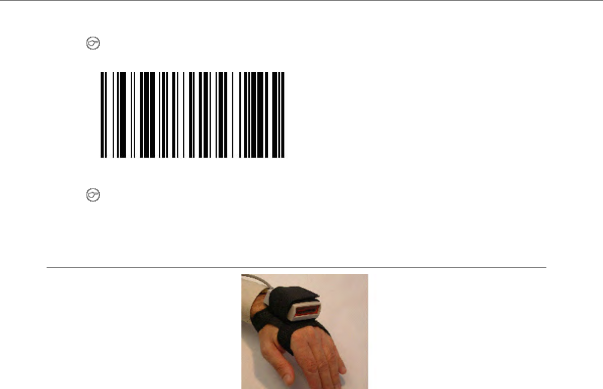
Note: Performing this step ensures that the scanner does not generate spurious Bluetooth RF
that could interfere with other transmissions.
Figure 131: Reset Scanner as Slave
Note: To pair the scanner again, rescan the Talkman code 128 barcode.
Honeywell IS4225 Bar Code Reader
Figure 132: Honeywell (Metrologic) IS4225 Bar Code Reader replaces the IS4220
• The small hole at the rear of the bar code reader near the cable is the speaker that the reader uses
to provide a confirming "beep" when a code has been successfully read. It is not a reset button. Objects
should not be pushed through this opening because they will damage the speaker and possibly cause
the reader to malfunction. This type of damage is not considered a warranty/repair item.
• For detailed specifications for this product, visit the Honeywell website.
Honeywell IS4220 Bar Code Reader Specifications
Bar Code Reader Firmware Defaults
• The reader transmits at 9600 baud, 8 bits, no parity, 1 stop bit.
• The default suffix values of Carriage Return (hex 0D) and Line Feed (hex 0A) are sent after each
scan.
• A confirming ‘beep’ tone is heard after each scan.
• Code scanned must be a minimum of 3 characters.
• Codes UPC, EAN, Code 39, Codabar, Code 128, Code 93, Interleaved 2 of 5 are enabled.
Vocollect RJ11 Connection Cable
• The Vocollect RJ11 connection cable (Symbol part # 735058) is used to connect a to a device.
• This connection cable has a Vocollect connector on one end (which connects to the device) and an RJ11
connector on the other end. Additional Symbol parts that are needed are as follows:
Confidential: For informational use by Vocollect Resellers and customers only
182 | Vocollect Hardware Documentation

Part # RS1-I01010-00 RS1 Ring Scanner•
• Part # 21-40727-01 Ring Scanner Decoder
• Part # 25-37384-02 Cable from the RS 1 Ring Scanner to the decoder
Resetting the Honeywell IS4220 Bar Code Reader to Firmware Defaults
• Print this page and scan the following from top to bottom. A confirming beep will be heard after each
scan.
Figure 133: Enter Program Mode
Figure 134: Recall All Defaults
Figure 135: Exit Program Mode
Honeywell MS9535 Bluetooth Bar Code Reader
The Honeywell (Metrologic) MS9535 VoyagerBT paired with Talkman A500 or T5 series devices with
the proper setup or paired with Talkman T2 series devices via the T2x Bluetooth Serial Adapter allows
operators to perform cordless scanning with their voice-directed work.
Confidential: For informational use by Vocollect Resellers and customers only
Bar Code Readers and Printers | 183
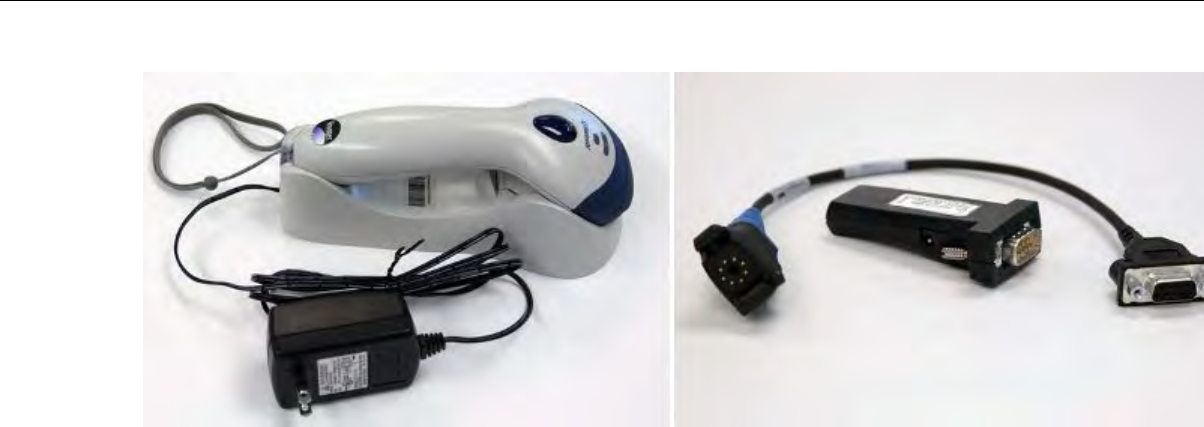
Figure 136: Honeywell MS9535 Bluetooth Bar Code Reader and T2x Bluetooth Serial Adapter
• The Vocollect A500 and T5 Series devices can pair with the Honeywell scanner, either as initiators
or acceptors. The setup includes settings in VoiceConsole and scanning the appropriate bar codes.
• Use barcode software to generate a barcode for pairing the Vocollect T2x Bluetooth Serial Adapter
and Honeywell reader dynamically.
• Always take hold of the bar cade reader by its handle.
• Never remove the reader from a resting place by pulling on the reader's cable.
• When not in use, the bar code reader should be secured.
• For details, see the manufacturer's website.
Honeywell MS9535 Bluetooth Bar Code Reader Specifications
Bar Code Reader Firmware Defaults
• The Honeywell MS9535 must be at firmware version 10547 or newer in order to correctly operate
with the T2x Series Bluetooth Serial Adapter
• The reader transmits at 9600 baud, 8 bits, no parity, 1 stop bit
• The default suffix values of Carriage Return (hex 0D) and Line Feed (hex 0A) are sent after each scan
• Set to keep-power-on ("BarcodeKeepPowerOn" must be set in the task to maintain a consistent
connection with the Bluetooth Adapter)
• Beep sequences are heard on successful connection or reconnection with the Bluetooth Adapter and
when the scanner is out of range of the Adapter (generally, greater than 30 feet or 10 meters).
• A confirming beep tone is heard after each scan
• A "razz" tone and flashing white status light are generated after a scan when the scanner is not
communicating with the Bluetooth Adapter
• Code scanned must be a minimum of 3 characters
• Codes UPC, EAN, Code 39, Codabar, Code 128, Code 93, Interleaved 2 of 5 are enabled
Vocollect Part Numbers
• Part # BC-611-1 Bluetooth Scanning Kit (Honeywell MS 9535BT Scanner, charging cradle, T2x
Bluetooth Adapter, and carrying pouch)
• Part # BC-611-102 Bar Code Scanner (Honeywell MS9535BT Scanner and charging cradle)
• Part # BC-611-105 T2x Bluetooth Serial Adapter and Carrying Pouch
• Part # BC-611-103 Carrying Pouch, Bluetooth Serial Adapter
Confidential: For informational use by Vocollect Resellers and customers only
184 | Vocollect Hardware Documentation
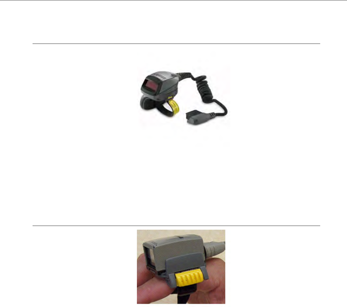
Motorola RS409 Wearable Ring Scanner
Figure 137: Motorola RS409 Wearable Ring Scanner
• Supported with WT4090 wearable terminals only.
• Never remove the scanner from a resting place by pulling on the scanner’s cable.
• When not in use, the bar code reader should be secured.
• For detailed specifications for this product, see Motorola's website.
Socket Cordless Ring Scanner Series 9M
Figure 138: Socket®Cordless Ring Scanner Series 9M
• The Cordless Ring Scanner (CRS) requires Vocollect VoiceClient 3.1 or later and is only compatible
with Talkman A500/T5 devices. Support is not currently provided on other Vocollect hardware or
software versions for this product.
• The documentation included with the Socket Cordless Ring Scanner (CRS) Series 9M from Socket
Communications includes utility software and references for use with the scanner and PC applications.
This software is not to be used in conjunction with Talkman A500/T5 wearable computers and should
not be installed. References in the documentation to PC applications and control of the CRS from PC
applications should be ignored.
• Other documentation from Socket Communications regarding general use, specifications, and bar
codes to control scanner functions is applicable to use with Vocollect Voice®systems.
• For detailed specifications and safety information, and for procedures for charging the battery and
assembly, refer to Socket's CRS documentation.
Confidential: For informational use by Vocollect Resellers and customers only
Bar Code Readers and Printers | 185

Wearing a Socket CRS
1. Insert the wrist unit (the large component of the CRS that contains the battery) into the protective
case, pulling the cable through the hole at the top of the case. The case protects the CRS from damage,
but its use is not required. If you do not choose to use the case, attach the two Velcro®strips directly
to the Bluetooth unit.
2. Connect the free end of the cable to ring scanner.
3. Attach the finger strap to the bottom of the ring scanner.
4. Put on the wrist strap and adjust it so it is secure and comfortable.
5. Put the ring scanner on your index finger and adjust the finger strap so it is secure and comfortable.
6. Attach the wrist unit to the wrist strap by pressing the Velcro strips together.
Documentation from Socket Communications
The documentation included with the Socket Cordless Ring Scanner (CRS) Series 9M from Socket
Communications includes utility software and references for use with the scanner and PC applications.
This software is not used in conjunction with the Talkman T5 devices and should not be installed.
References in the documentation to PC applications and control of the CRS from PC applications should
be ignored.
Other documentation from Socket Communications regarding general unit use, specifications and bar
codes to control scanner functioning is applicable to use with Vocollect Voice systems.
Scanning
Press the trigger button and aim your finger at the bar code. The red laser beam should cover the entire
width of the bar code. Please refer to the Socket User’s Guide for scanning tips. When data is read and
sent to the mobile computing device, the laser will turn off. Depending on the scanner settings, the ring
scanner’s LED may flash green to indicate a good read.
Configuring a Socket CRS
You must set the following configurable parameters to the Recommended Values to support the use of
the Socket CRS:
Recommended
Value
ValuesDescriptionParameter
600000 to 60000Sets the time (in milliseconds)
VoiceClient will wait for data from the
BarcodeBufferDataTimeout
peripheral device before the entire raw
data buffer is cleared.
1 = enableDefault = 750
0 = disable
Parses the barcode data for characters
(<CR<, <LF<, NULL) that are
incorrectly prefixed and removes them
if found.
BarcodeCleanPrefixedChars
1 = enable
1 = enable0 = disable
1 = enable
Prints additional lines of debug detailing
the data received from the peripheral
device and what data is cleared if the
BarcodeBufferDataTimeout is exceeded.
BarcodeVerboseDebug
Pairing the Socket Cordless Ring Scanner with a Talkman T5
During use, it is possible for the scanner to disconnect from the device if the communication link is
disrupted. When the scanner is setup so that the device initiates the connection, the device typically
Confidential: For informational use by Vocollect Resellers and customers only
186 | Vocollect Hardware Documentation

recovers the connection automatically. When the scanner initiates the connection, it typically requires
the press of a button to activate and recover the connection..
The Bluetooth connection between the Socket®Cordless Ring Scanner (CRS) and a Talkman T5 is
managed through VoiceConsole. See VoiceConsole Help for details on the use of Bluetooth with Vocollect
Voice systems.
Note that Each CRS has a unique Bluetooth address that is clearly labeled on the underside of the
wrist-worn Bluetooth transmitter and battery pack. This address is needed to associate a CRS with a
T5.
Because a T5 will be explicitly associated with a specific CRS via VoiceConsole, Vocollect strongly
recommends clearly labeling the CRS wrist units to identify them with the specific T5 to which they are
paired. A clear identification and operational procedure for keeping specific scanners associated with
specific Talkman T-Series devices will be beneficial in the work environment.
Connecting the CRS to the Talkman T5 Device
The Socket Cordless Ring Scanner, with scanner part number ending in REV D, can be paired with a
T5-series device where the scanner acts as the initiator.
You must have access to VoiceConsole to set up the pairing. For production use, Vocollect recommends
that you create a specific device profile in VoiceConsole to store many of the following settings.
1. In VoiceConsole, select Bluetooth scanner as the pairing type for the device you want to pair with
the scanner. For the Connection Mode, select Device listens for peripheral connection. See VoiceConsole
Help for details.
2. Create a bar code using Symbology Code 128 in the following form, where AABBCCDDEEFF is the
Bluetooth MAC address found on the T5: #FNIAABBCCDDEEFF#
a) Bar codes can be created at a Web site such as www.barcoding.com/upc.
3. Turn on the Socket CRS and the T5.
4. Scan the bar code you created.
The scanner beeps and begins flashing rapidly. It is now searching for the device.
5. Place the scanner and device closely together to pair.
The Bluetooth LED on the scanner blinks once every four seconds to indicate that the scanner and
device have paired.
Setting up for Carriage-Return (CR) and Line Feed (LF) Termination
It is likely that the scanner will need to minimally be set to send a carriage-return (CR) and line-feed
(LF) character, hexadecimal 13 and 10 respectively. Scanning each bar code from the sequence below
from top left to bottom right will:
• Initialize the scanner to defaults (top right bar code, may be omitted if not needed)
• Set Scan Suffix 1 to be a carriage return (next 5 bar codes)
• Set Scan Suffix 2 to be a line feed (top right 5 bar codes)
• Request scans be formatted with scanned data followed by Suffix 1 and then Suffix 2 (bottom right
bar code)
Confidential: For informational use by Vocollect Resellers and customers only
Bar Code Readers and Printers | 187
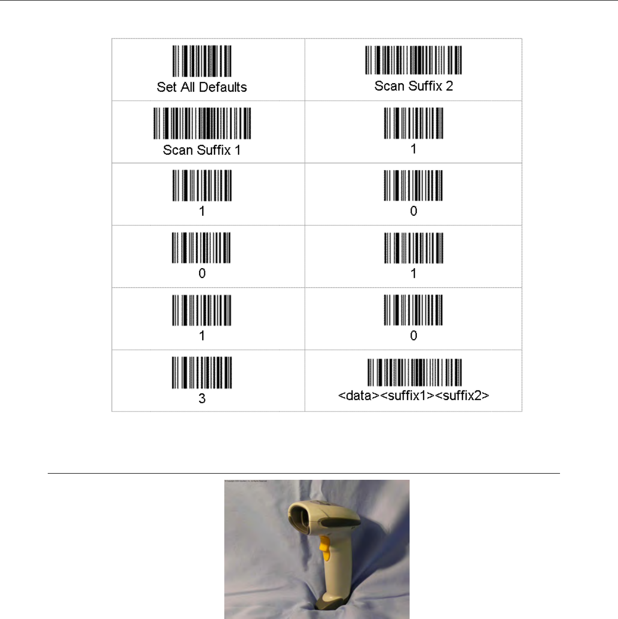
Symbol LS4208 Bar Code Scanner
Figure 139: Symbol LS4208 Bar Code Gun
• Always take hold of the Symbol®bar code scanner by its handle.
• Never remove the scanner from a resting place by pulling on the scanner’s cable.
• When not in use, the bar code scanner should always be placed back into its holster.
• For detailed specifications for this product, visit Symbol’s website.
• The Symbol LS4208 bar code scanner and holster are sold separately.
Confidential: For informational use by Vocollect Resellers and customers only
188 | Vocollect Hardware Documentation

Programming Symbol LS4208 Bar Code Scanners
You can program the Symbol LS4208 bar code scanner to match the default settings of a Talkman device.
The default settings are:
• 9600 baud
• 8 data bits
• No parity
• 1 stop bit
1. Print this page.
2. Scan the following code to ensure that the scanner's parameters are set to the default settings.
Figure 140: Set All Defaults
3. Scan the following Scan Options bar code to change the scan data format.
Figure 141: Set Scan Options to Change Data Format
4. Scan the following bar code to set the scan data format to <DATA> <SUFFIX>.
Figure 142: Set to Data Format to <DATA> <SUFFIX>
5. Scan the following Enter bar code to complete the data format change.
Figure 143: Set Data Format Change
Confidential: For informational use by Vocollect Resellers and customers only
Bar Code Readers and Printers | 189
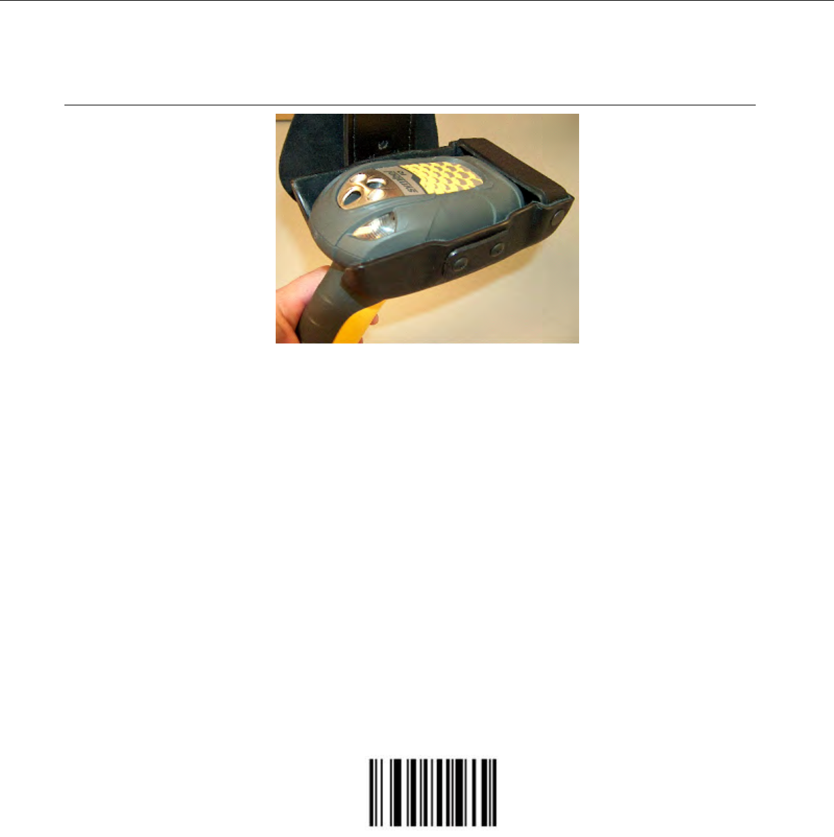
Symbol LS3408-FZ20005/LS3408-ER20005 Bar Code Scanners
Figure 144: Symbol Bar Code Reader
• Always take hold of the Symbol®bar code scanner by its handle.
• Never remove the scanner from a resting place by pulling on the scanner’s cable.
• When not in use, the bar code reader should be secured.
• For detailed specifications for this product, visit Symbol’s website.
• The Symbol LS3408-FZ20005 bar code reader and holster are sold separately.
Programming Symbol LS3408 Bar Code Scanners
You can program the Symbol RS-1 Decoder and the Symbol LS3408-FZ2005 bar code scanner to match
the default settings of a Talkman device.
The default settings are:
• 9600 baud
• 8 data bits
• No parity
• 1 stop bit
• 2 terminating characters (0x0d and 0x0a)
1. Print this page.
2. Scan the following code to ensure that the scanner's parameters are set to the default settings.
Figure 145: Set All Defaults
3. Scan the following bar code to set the RS 1 so that it does not use parity.
Confidential: For informational use by Vocollect Resellers and customers only
190 | Vocollect Hardware Documentation

Figure 146: Set Parity to None (0x04)
4. Scan the following bar code to set the RS 1 to send two terminating characters (suffix).
Figure 147: Set to Send Two Terminating Characters--Data, Suffix1, Suffix2 (0x03)
5. Scan the following bar code to program terminating character 1 (suffix 1).
TermChar1 (suffix 1) = 1013 = 0x0D = Carriage Return
Figure 148: Scan Suffix 1
6. Scan the following four bar codes to enter the character information.
1
0
1
3
Confidential: For informational use by Vocollect Resellers and customers only
Bar Code Readers and Printers | 191

7. Scan the following bar code to program terminating character 2 (suffix 2).
TermChar2 (suffix 2) = 1010 = 0x0A = Line Feed
Figure 149: Scan Suffix 2
8. Scan the following bar codes to enter the character information.
1
0
1
0
Symbol RS 1 Ring Scanner and Decode Block Bar Code Reader
• The Symbol®RS 1 Ring Scanner is a non-decoded bar code reader that must use an external decode
block to connect to the device.
Confidential: For informational use by Vocollect Resellers and customers only
192 | Vocollect Hardware Documentation
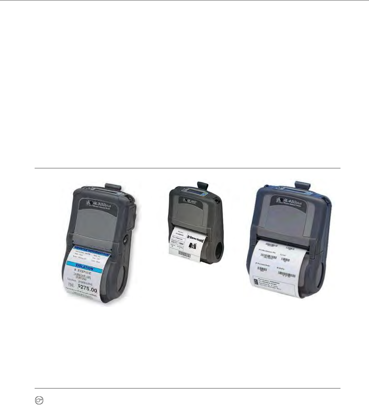
• The Vocollect RJ11 connection cable (Symbol part # 735058) is used to connect a Symbol RS 1 Ring
Scanner to a device. This connection cable has a Vocollect connector on one end (which connects to
the device) and an RJ11 connector on the other end.
• For detailed features and specifications of the Symbol RS 1 ring scanner, please refer to the
manufacturer's website.
Symbol RS 1 Ring Scanner and Decode Block Bar Code Reader Specifications
Ring Scanner Firmware Defaults
• Scanner transmits at 9600 baud, 8 bits, no parity, 1 stop bit
• Enabled to decode: UPC/EAN, Code 128, Code 39, Interleaved 2 of 5
• Disabled from decode: Code 93, Discrete 2 of 5, Codabar, MSI Plessey, RSS
• No prefixes & suffixes added
Zebra QL 320 Plus and 420-Series Mobile Printers
Figure 152: Zebra QL 420 Plus
Figure 151: Zebra QL 420
Figure 150: Zebra QL 320 Plus
• For detailed specifications for this product, visit Zebra’s website.
Vocollect Connector Pin Specifications
Note: Cable colors may change without notice. Please contact Vocollect with any questions regarding
this procedure.
Confidential: For informational use by Vocollect Resellers and customers only
Bar Code Readers and Printers | 193
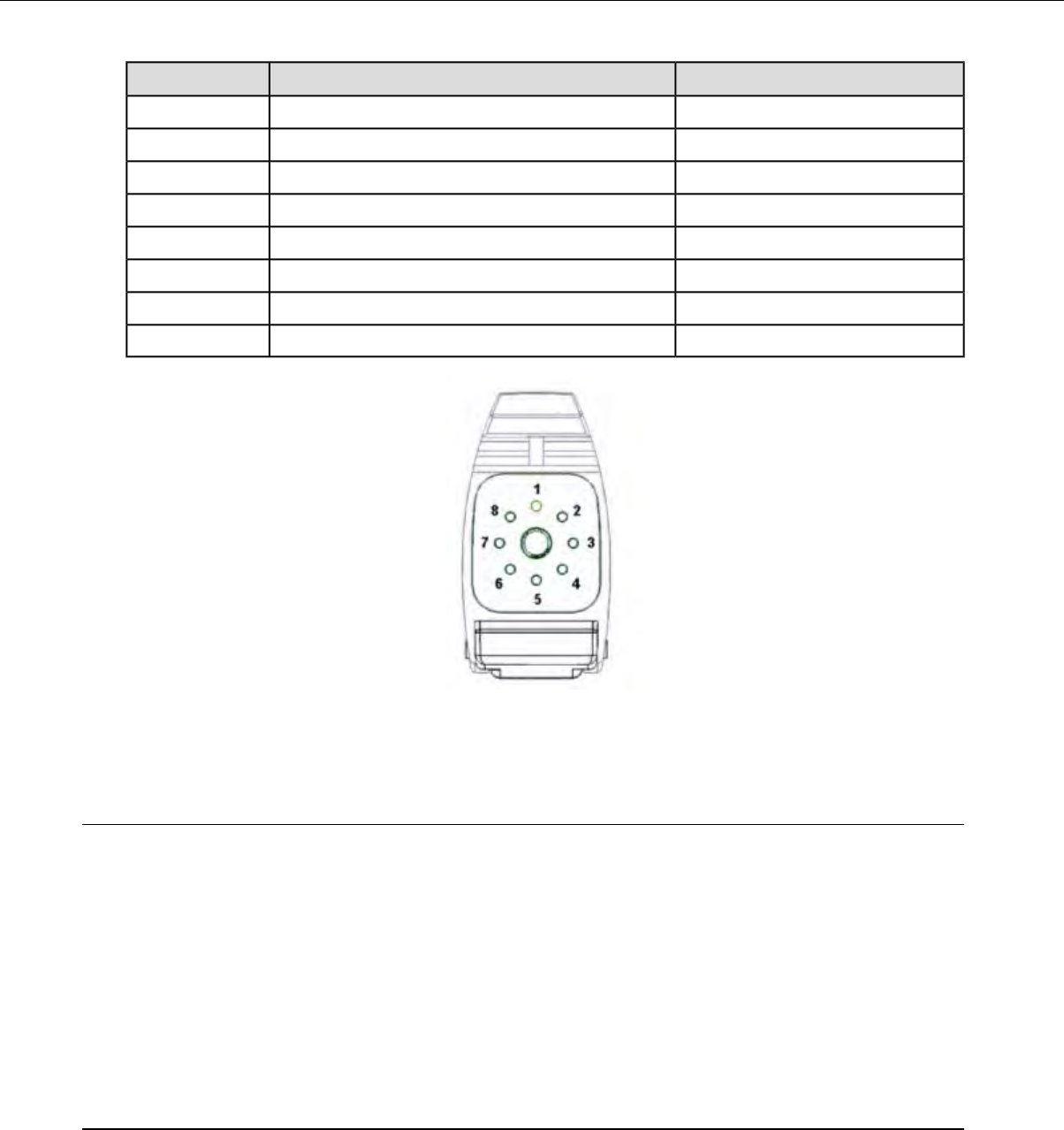
ColorPurposePin
Bare WireNot used1
RedPower (+5 volts)2
WhiteNot used3
GreenNot used4
BlueReceive data (RXD)5
GrayTransmit data (TXD)6
OrangeNot used7
BlackGround8
Figure 153: Vocollect Connector Pin Specifications
Vocollect Bar Code Device Adapter
•The Vocollect bar code device adapter connects compatible RS-232 bar code devices to Talkman devices.
• The bar code device that is being connected to the Talkman device must meet the following criteria:
• The device must support RS-232.
• The device must be decoded (as opposed to undecoded).
• The device must operate on five volts (+5V).
• This adapter is to be used only with bar code devices that are not powered through their own RS-232
connection.
Vocollect Bar Code Serial Interface Cable
• All equipment design and technical information contained within this document is the confidential
property of Vocollect, Inc. No use or disclosure thereof may be made without written permission from
Vocollect, Inc.
• The Vocollect bar code serial interface cable (part # BC-606-1) connects compatible bar code readers
to devices.
Confidential: For informational use by Vocollect Resellers and customers only
194 | Vocollect Hardware Documentation
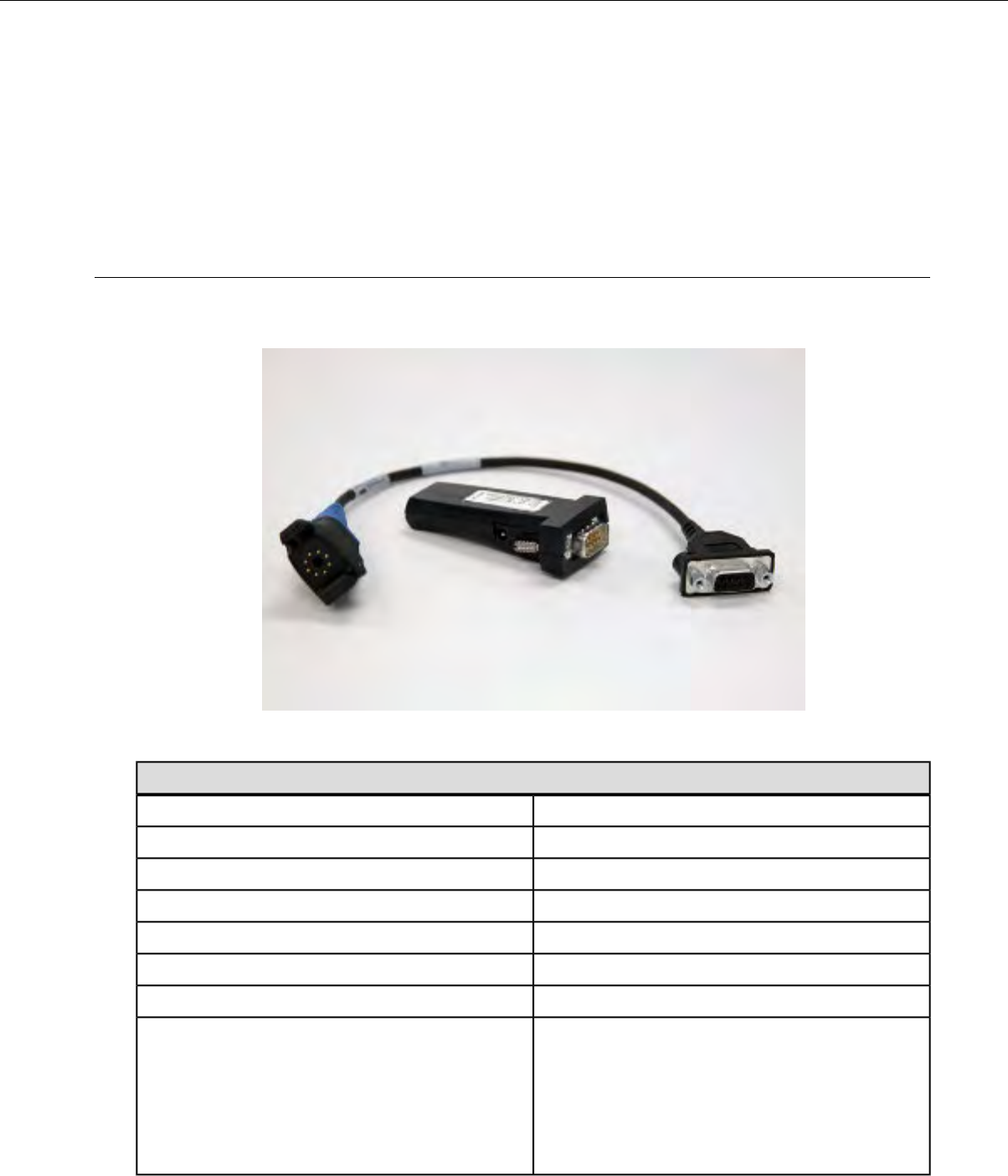
• The serial device that is being connected to the device must meet the following criteria: The device
must support serial communications. The device must be decoded (as opposed to undecoded). The
device must operate on five volts (+5V).
• For proper operation, the ground, power, and receive data connections must be made.
• The transmit data (TXD) connection from the serial device must be connected to the receive data
(RXD) connection of the Vocollect cable.
Vocollect T2 Series Bluetooth Adapters Specifications
The T2x Bluetooth Serial Adapater (part number BC-611-105) replaces the T2 Series Bluetooth Adapter
(part number BC-611-104). The T2 Series adapter is discontinued.
Figure 154: T2x Bluetooth Serial Adapter
T2x Bluetooth Serial Adapter
IntegratedAntenna
921,600 KB/sBaud Rate
0° to 70° C (32° to 158° F)Operating Temperature
20% to 75% non-condensingOperating Humidity
8% to 95% non-condensingStorage Humidity
3.8 feet (10m)Range
RS-232, 9 pin maleSerial COM Interface Standard
Bluetooth 1.1 Qualified
AEO C-TPAT WEEE RoHS
Compliance
EMC: CE
FCC Compliant
TAA
Confidential: For informational use by Vocollect Resellers and customers only
Bar Code Readers and Printers | 195
T2x Bluetooth Serial Adapter
Serial PortBluetooth Profile
Legacy T2 Series Bluetooth Adapter
Integrated Class 2 Bluetooth ModuleAntenna
9600 bpsBaud Rate
-20° to 85° C (-4° to 185° F)Operating Temperature
5% to 95% non-condensingHumidity
-40° to 95° C (-40° to 203° F)Storage Temperature
Approximately 10m (32.8 feet)Range
RS-232Serial COM Interface Standard
Bluetooth 1.1
FCC: Part 15, Class B
Compliance
Industry Canada
CD: ETC 300 328, ETC 300 826
C-Tick S.182
Serial PortBluetooth Profile
The Bluetooth word mark and logos are owned by the Bluetooth SIG, Inc., and any use of such marks
by Honeywell is under license. Other trademarks and trade names are those of their respective owners.
See Advanced Settings in VoiceConsole Help for task parameters for the Bluetooth Serial Adapter.
Connecting Peripherals to a Talkman Device
For T2 Series devices, match the color on the device's connection port to the color on the connector.
• Headsets: Yellow port
• Bar code readers: Blue port
• Visual training devices, wired portable speakers, wireless listening systems, portable printers: Red
port
For A500 and T5 devices, match the color on the device's connection port to the color on the connector.
• Headsets: Yellow port
• All other peripherals: The port designated by red and blue triangles
Note: When you attach a peripheral to an A500 or T5-series device, the device may automatically
shut down if the peripheral is powered on when attached to the cable. If this happens, reboot the
device.
1. Attach the cable to the device.
Confidential: For informational use by Vocollect Resellers and customers only
196 | Vocollect Hardware Documentation
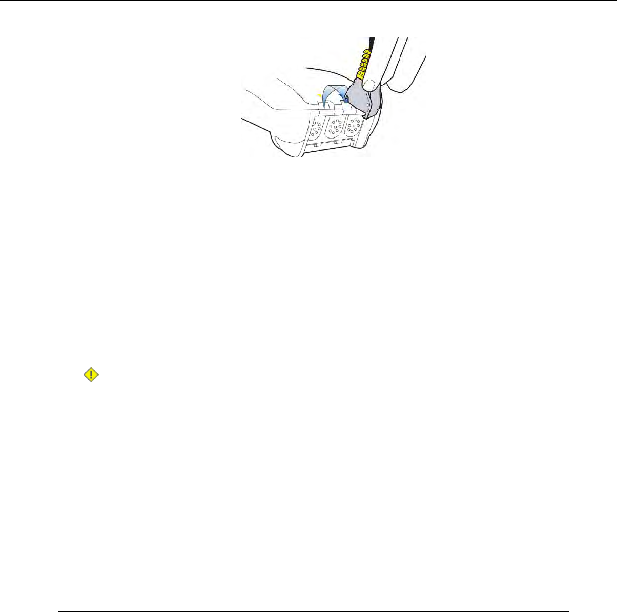
Figure 155: Connecting the Cable to the Talkman Device
2. Make sure the peripheral is off.
3. Connect the cable to the peripheral.
4. Turn the peripheral on.
• To connect the SL-4 light duty behind-the-head headset to a Talkman T1 device, insert the IOC
connector on the end of the headset cable into the connection port on the T1 device.
• To connect the SR-21 Universal Lightweight Headset to a handheld device, insert the 2.5mm
universal connector on the end of the headset wire into the connection port on the handheld device.
Disconnecting Peripherals from a Talkman Device
Caution: Never pull on the cable or twist the connector to disconnect it from the device. Doing so
will damage the cable and connector, and invalidate the headset's warranty.
1. Grasp the connector.
2. Press the connector's release lever.
3. Tilt the bottom of the connector off the device.
4. Lift the connector up and off the device.
• To disconnect the SL-4 light industrial behind-the-head headset from a Talkman T1 device, grasp
the IOC connector on the end of the headset cable and pull it out of the connection port on the T1
device. Do not pull the headset wire.
• To disconnect the SR-21 Universal Lightweight Headset from a handheld device, grasp the 2.5mm
universal connector on the end of the headset wire and pull it out of the connection port. Do not
pull the headset wire.
About Pairing Peripheral Devices
• Pairing recommendations may differ from peripheral to peripheral and configuration. Please see your
device and peripheral documentation.
• If you are using Bluetooth, ensure that the Bluetooth radio has been turned on through the device's
operating system. Most devices have the ability to turn the Bluetooth radio on or off. For power
consumption reasons, when Bluetooth is not in use, the Bluetooth radio should be turned off. This
process differs per device. Please see your device and peripheral documentation.
Confidential: For informational use by Vocollect Resellers and customers only
Bar Code Readers and Printers | 197

• If the peripheral with which you are trying to pair does not show up on the list of devices within
range, that peripheral may already be paired with another device. Disconnect the pairing and scan
for the desired peripheral again.
• A Bluetooth scanner should beep when it pairs with a device. If you do not hear a tone, restart the
handheld device.
• At the end of a shift, disconnect any active Bluetooth pairing so that the peripheral is free to pair
with another device. You can do this via VoiceConsole by in Device Management.
• Pairings with additional Bluetooth peripheral devices can greatly affect the performance of paired
printers and scanners. To improve performance, delete pairings that are not in use from the device.
Note: See Vocollect VoiceConsole help for details on how to pair and manage devices using
VoiceConsole.
Pairing a Bluetooth Scanner or Printer With a Honeywell LXE Device
This procedure is for:
• MX7 Handheld Computer
• HX2 Wearable Computer
1. Ensure Bluetooth is enabled on the device and the scanner/printer is on.
When Bluetooth is enabled on the device, the Bluetooth indicator blinks blue on the device. and the
icon displays in the taskbar.
2. In the Control Panel, doubletap Bluetooth.
3. In the Bluetooth Devices tab of the Pairing window, tap Discover. Wait while the device scans
for Bluetooth peripherals within range.
4. When the device finishes scanning, find your printer or scanner by locating it in the Bluetooth
Devices list
5. Doubletap the name of your printer or scanner.
The device properties list displays.
6. Tap Pair as Scanner or Pair as Printer.
Pairing a Bluetooth Printer With a Psion Device Running Windows Mobile
Note: Psion devices running Windows Mobile is only supported on Vocollect Voice for Handhelds
1.3 and earlier.
1. Ensure Bluetooth in enabled.
2. On the Devices tab, tap Add new device and follow the onscreen prompts while it searches for your
Bluetooth printer.
3. Ensure the printer's COM port number matches the COM port number of the task package in
VoiceConsole.
4. Apply the PrinterPort advanced setting to your task, with the port number equal to BSPxor COMx,
where xis the number of the printer's COM port.
5. Load the updated task onto your device.
Pairing a Bluetooth Scanner or Printer With a Psion Device Running Windows CE
This procedure is for:
• WORKABOUT Pro®Speech™3 (7527) devices running Vocollect Voice 1.2 for Psion®WORKABOUT
Pro®7527 or newer
Confidential: For informational use by Vocollect Resellers and customers only
198 | Vocollect Hardware Documentation

•WORKABOUT Pro®Speech™G2 (7527) devices running Vocollect Voice 1.3 for Psion®WORKABOUT
Pro®Speech 3, WORKABOUT Pro Speech G2 and NEO
• NEO™devices running Vocollect VoiceClient 1.3. for Psion®WORKABOUT Pro®Speech 3,
WORKABOUT Pro Speech G2 and NEO
1. In the Control Panel, open Power.
2. In the Built-in Devices tab of the Power Properties window, activate the Enable Bluetooth
check box.
3. Tap OK.
When Bluetooth is enabled, the icon displays in the taskbar.
4. In the Control Panel, open Bluetooth.
5. In the Device tab of the Bluetooth window, tap Scan. Wait while the device scans for Bluetooth
peripherals within range.
6. When the device finishes scanning, find your printer or scanner by locating its Bluetooth address in
the Address list
7. Tap the name of your printer or scanner.
8. Tap Pair.
The Services window opens.
Note: If an authentication window displays and the peripheral does not require a passcode, tap
Next.
9. Activate the Serial Port check box.
The Serial Profile window opens.
10. Ensure Encryption is set to Disabled.
11. If you are pairing a printer, select Printer from the Mode drop-down list. If you are pairing a scanner,
select Scanner from the Mode drop-down list.
12. Select the first BSP port available in the Port drop-down list.
13. Tap Next.
The Services window opens displaying the peripheral and the port.
14. Tap Done.
15. Tap OK.
16. Ensure the printer or scanner's BSP port number matches the BSP port number of the task package
in VoiceConsole.
17. Apply either the BarcodePort or PrinterPort advanced setting to your task, with the port number
equal to BSPx, where xis the number of the printer or scanner's BSP port.
18. Load the updated task onto your device.
Pairing a Bluetooth Scanner or Printer With a Psion WORKABOUT PRO G2 Device Running
Windows CE
This procedure is for WORKABOUT Pro Speech™G2 (7527) devices running Vocollect VoiceClient 1.2
for Psion WORKABOUT PRO 7527.
1. Open Wireless Manager.
2. Activate the Enable Bluetooth check box.
3. Tap OK.
When Bluetooth is enabled, the icon displays in the taskbar.
4. In the Control Panel, open Bluetooth Devices.
Confidential: For informational use by Vocollect Resellers and customers only
Bar Code Readers and Printers | 199

5. On the Properties tab, change the Port Prefix to BSP.
6. In the Devices tab of the Bluetooth Manager window, tap Scan. Wait while the device scans for
Bluetooth peripherals within range.
7. When the device finishes scanning, find your printer or scanner by locating its Bluetooth address in
the Address list.
8. Tap the name of your printer or scanner.
9. Tap Services.
10. Double-click the type of peripheral (printer or scanner) that you want to pair.
11. Select Active from the popup box.
The corresponding BSP port appears under the Port column.
12. Ensure the printer or scanner's BSP port number matches the BSP port number of the task package
in VoiceConsole.
13. Apply either the BarcodePort or PrinterPort advanced setting to your task, with the port number
equal to BSPx, where xis the number of the printer or scanner's BSP port.
14. Load the updated task onto your device.
Pairing a Bluetooth Scanner With an Intermec CK3 or 70-Series Device Using Search
1. Make sure the scanner is on and is discoverable. See the scanner’s documentation for more information.
2. On the Intermec device, tap Start >Settings.
3. On the System tab of the Settings screen, tap Wireless Scanning.
4. On the Wireless Scanner screen, tap Add Device.
5. Select if want to search for all available Bluetooth scanners, and tap Next.
The device searches for all Bluetooth devices within range to which it can be paired. Once the search
has completed, the device displays the Bluetooth devices found.
If you do not see the scanner you want to pair within the list, deselect the Scanners Only checkbox.
If the scanner is still not available within the list, ensure the scanner is on and is discoverable, and
tap Search.
6. Select the scanner from the Devices list.
7. Under Connection Method, select Data Collection if you are pairing with an Intermec device or
select Serial Port if you are pairing with a different type of scanner.
8. Tap Next.
9. If you selected Serial Port, select the serial port you want to use for the scanner, and tap Next.
Note: It is important you remember the serial port you select. After you finish setting up the
scanner, you must edit or enter the value of the BarcodePort advanced setting with this serial
port.
10. Tap Finish.
If you selected Data Collection, the scanner pairs with the Intermec device. If you selected Serial
Port, the scanner does not pair with the Intermec device until you complete the next step.
11. If you selected Serial Port as the connection method for the scanner, you must now enter or edit the
value of the BarcodePort advanced setting to equal the serial port you assigned to the scanner, for
example: BarcodePort=BSP3.
Confidential: For informational use by Vocollect Resellers and customers only
200 | Vocollect Hardware Documentation

Pairing a Bluetooth Scanner With an Intermec CK3 or 70-Series Device Using Quick
Connect
Note: The following processes assume use of the Intermec device as the initiator. If you would like
to configure your scanner to be the initiator of the pairing, see the scanner’s documentation for more
information. If you pair the scanner with the scanner as the initiator and assign the scanner to a
serial port, you must enter or edit the value of the BarcodePort advanced setting to equal the serial
port after you pair for the scanner and Intermec device to be properly paired.
1. Make sure the scanner is on and is discoverable. See the scanner’s documentation for more information.
2. On the Intermec device, tap Start >Settings.
3. On the System tab of the Settings screen, tap Wireless Scanning.
4. On the Wireless Scanner screen, tap Add Device.
5. Select if you are pairing an Intermec scanner, and tap Next.
6. Scan the barcode that appears on the screen with the Intermec scanner.
A Bluetooth dialog box opens.
7. In the Bluetooth dialog box, tap Yes to add the scanner to the list of devices paired with the Intermec
device.
8. If prompted, enter the passcode for the scanner, and tap Next.
9. Tap Finish.
The scanner pairs with the Intermec device.
Pairing a Bluetooth Scanner With an Intermec CK3 or 70-Series Device Manually
1. Make sure the scanner is on and is discoverable. See the scanner’s documentation for more information.
2. On the Intermec device, tap Start >Settings.
3. On the System tab of the Settings screen, tap Wireless Scanning.
4. On the Wireless Scanner screen, tap Add Device.
5. Tap Next.
6. Enter the scanner’s Bluetooth address.
7. If you selected Serial Port, select the serial port you want to use for the scanner, and tap Next.
8. Under Connection Method, select Data Collection if you are pairing with an Intermec device or
select Serial Port if you are pairing with a different type of scanner.
9. Tap Next.
10. If you selected Serial Port, select the serial port you want to use for the scanner, and tap Next.
Note: It is important you remember the serial port you select. After you finish setting up the
scanner, you must edit or enter the value of the BarcodePort advanced setting with this serial
port.
11. Tap Finish.
If you selected Data Collection, the scanner pairs with the Intermec device. If you selected Serial
Port, the scanner does not pair with the Intermec device until you complete the next step.
12. If you selected Serial Port as the connection method for the scanner, you must now enter or edit the
value of the BarcodePort advanced setting to equal the serial port you assigned to the scanner, for
example: BarcodePort=BSP3.
Confidential: For informational use by Vocollect Resellers and customers only
Bar Code Readers and Printers | 201
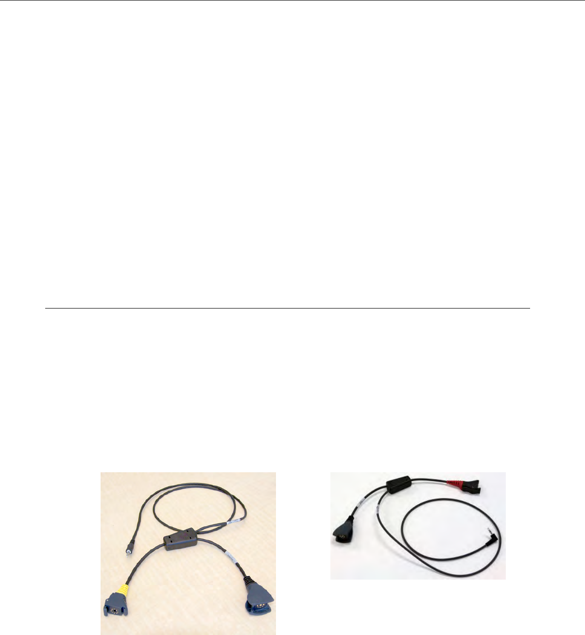
Configuring an Intermec Device for Bar Code Reader Input to Vocollect Voice
How to configure an Intermec handheld device so that Vocollect Voice can accept input from an external
bar code reader.
These steps must be performed after pairing an Intermec device to a bar code reader.
1. On the Intermec device, tap Start >Settings.
2. On the System tab of the Settings screen, tap Intermec Settings.
3. On the Intermec Settings screen, tap Data Collection.
The scanner's name will appear on the Data Collection screen.
4. Select the scanner.
A list of available settings will appear.
5. Select Scanner Settings.
6. Activate the Hardware Trigger check box.
7. Tap OK.
Vocollect Voice will now allow input from the external scanner you are using.
Accessories
Vocollect offers a variety of accessories for wearing, protecting, and facilitating the operations of Talkman
and other handheld devices.
Inline Adapter Cables: Talkman Devices and Handheld Devices
Most inline adapter cables are made for a specific handheld device, so be sure to use the correct adapter
for your device.
A device-specific inline adapter training cable, also referred to as a "Y" or splitter cable, must be used
with third-party handheld devices in order to connect both a Vocollect headset and listening system to
the device.
Inline adapter training cables must only be used with listening systems approved by Vocollect.
Figure 157: Training Cable (TR-603-102) for Talkman, Wired
Scanner, and Listening Kit
Figure 156: Training Cable (AD-300-1) for Handheld Device,
Headset and Listening Kit
Confidential: For informational use by Vocollect Resellers and customers only
202 | Vocollect Hardware Documentation
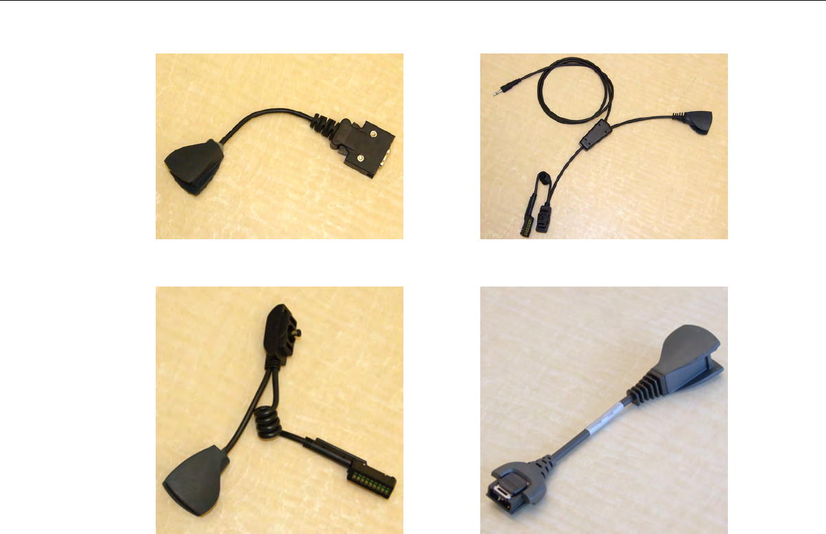
Figure 159: Honeywell LXE HX2 Training CableFigure 158: Honeywell LXE MX7 Headset Cable
Figure 161: Motorola WT4090 Headset CableFigure 160: Honeywell LXE HX2 Headset Cable
Connecting an Inline Adapter Cable to a Handheld Device
1. Connect your Vocollect SR-Series headset's connector to the matching end of the adapter cable.
2. Connect the other end of the adapter cable to the appropriate port on your handheld device.
Connecting Inline Adapter Training Cables
1. Connect your Vocollect SR-Series headset's connector to the matching end of the training adapter
cable.
2. Connect the 3.5 mm jack on the training cable to the input jack on your listening device.
3. Connect the other end of the training cable to the appropriate port on your handheld device.
Confidential: For informational use by Vocollect Resellers and customers only
Bar Code Readers and Printers | 203
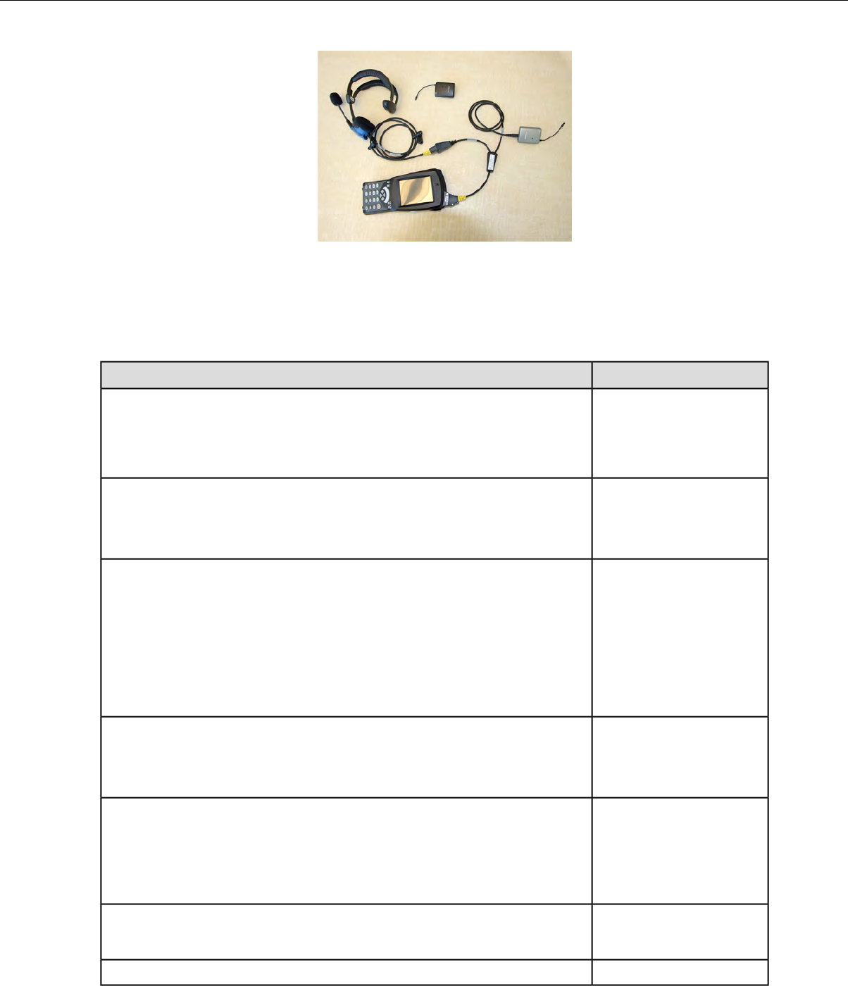
Figure 162: Typical Training Cable Setup
Part Number Index: Cables
Part Numbers for ordering cables
Vocollect Part NumberCable
BC-604-203Short “Y” cable.
Offers two connections, an RS232 DB9, and an unterminated connection
that provides ground on the black wire and +5V on the red.
Useful to connect a scanner which has a DB9 connection and requires power.
BC-606-1Straight cable
48” (1.2m)
unterminated*
BC-606-2Straight cable
48” (1.2m)
Terminated with RJ11
Pin 2 (Tx), 3 (Rx), 4 (Ground)
• pins numbered looking at male connector with connector lock on top
• pin #1 is leftmost
BC-606-3Coiled cable
48” (1.2m)
unterminated*
BC-606-6Coiled cable
79” (2m)
~48” (1.2m) uncoiled
unterminated*
BC-606-7Cable, Zebra QL series Printer
36” (.9m)
BC-610-101Cable, Symbol Gun Barcode Reader
Confidential: For informational use by Vocollect Resellers and customers only
204 | Vocollect Hardware Documentation

Vocollect Part NumberCable
58” (1.5m) coiled)
Terminated with RJ45
Pin 2 (5v), 3 (Ground), 4 (Rx)
• pins numbered looking at male connector with connector lock on top
• pin #1 is leftmost
*Unterminated cables use wires red (5V), blue (Rx), grey (Tx) and black (ground). All other wires are
not used.
Part Numbers: Bar Code Readers and Other Devices
Part Numbers for ordering bar code readers and bar code reader accessories
Vocollect Part NumberDevice or Accessory
BC-604-203Bar Code Device Adapter
BC-610-1Symbol LS3408-FZ20005 Bar Code Reader
BC-610-2Extended Range Scanner (Symbol LS3408-ER2005)
BC-609-1Honeywell (Metrologic) IS4220 Bar Code Reader
BC-609-1*Honeywell Glove Scanner (Metrologic®IS4220)
BC-609-101Replacement glove for Honeywell (Metrologic) IS4220x
BC-610-3Symbol LS4208 Bar Code Gun
BC-604-204Belt holster for gun scanners
BC-610-101Cable for BC-610-x
BC-611-1Bluetooth Scanning Kit (Honeywell MS 9535BT Scanner, charging
cradle, T2x Bluetooth Adapter, and carrying pouch)
BC-611-102Honeywell (Metrologic) MS9535 Voyager BT scanner & charger
BC-611-105T2x Bluetooth Serial Adapter and carrying pouch
BC-611-103Carrying pouch for T2x Bluetooth Serial Adapter
BC-606-1Serial Interface Cable
BC-606-2RJ11 Connection Cable
BC-613-1Barcode Scanner, Bluetooth™Ring (Honeywell LXE 8652) Kit (Ring
scanner, battery, 2 wrist straps)
BC-613-101Replacement Scanner, without Bluetooth™module (Honeywell LXE
8652)
BC-613-102Replacement Battery, Bluetooth™Ring Scanner (Honeywell LXE 8652)
BC-613-103Replacement Large Hand Wrist Strap, Barcode Scanner, Bluetooth™
Ring (Honeywell LXE 8652)
Confidential: For informational use by Vocollect Resellers and customers only
Bar Code Readers and Printers | 205

Vocollect Part NumberDevice or Accessory
BC-613-104Replacement Small Hand Wrist Strap, Barcode Scanner, Bluetooth™
Ring (Honeywell LXE 8652)
BC-613-105Replacement 8 Bay Battery Charger (Honeywell LXE 8652)
BC-613-106Replacement Single Bay Battery Charger (Honeywell LXE 8652)
BC-613-107Replacement Finger Strap (20 Pack), Barcode Scanner, Bluetooth™
Ring (Honeywell LXE 8652)
BC-613-108Replacement Finger Strap Assembly (20 Pack), Barcode Scanner,
Bluetooth™Ring (Honeywell LXE 8652)
BC-613-109US Power Cord Cable
BC-613-110Euro Power Cord Cable
BC-613-111British Power Cord Cable
DSP-100Pidion BM-170 Display
850-569-001Snap-on Adapter, Vocollect, Intermec 70 Series
850-819-001CK3 Cnap-on Audio Adpater for Vocollect headsets (AA22)
TM-CCK3-VP-KTTaylor Made CK3 Voice/Speech Holster Kit (includes adjustable belt,
adjustable belt strap, and adjustable leg strap - compatible with all
snap-on audio adapters)
TM-CCK71-VP-KTTaylor Made CK71 Voice/Speech Holster Kit (includes adjustable belt,
adjustable belt strap, and adjustable leg strap - compatible with
Intermec 70 Series snap-on audio adapters)
TM-CCN70-VP-KTTaylor Made CN70 Voice/Speech Holster Kit (includes adjustable back
snap web belt - compatible with Intermec 70 Series snap-on audio
adapters)
HH-S2626 oz. Belt Retractor
*BC-609-1 may be purchased directly form Honeywell as part number MK4220-301/VOC.
Confidential: For informational use by Vocollect Resellers and customers only
206 | Vocollect Hardware Documentation
Chapter 11
Vocollect Voice on Handheld Devices
Vocollect Voice extends the value of voice to users who perform multiple operations with handheld
devices. By installing Vocollect Voice on handheld display devices and scanners, you can take advantage
of the efficiency and ease of voice dialogs, Vocollect Adaptive Speech Recognition™, noise cancelation,
and multiple language support.
Adaptive Speech Recognition means that as the worker uses the system over time, Vocollect's speech
recognizer uses samples of his or her speech in different environments, at different volumes, and with
different inflections to update the worker's voice templates. As the recognizer accounts for changes in
speaking patterns, voice recognition improves and system performance improves.
Note that in order for adaptive voice recognition to work, the provider of your Vocollect Voice system
must include special recognizer hints called response expressions when developing the application.
Installing Vocollect Voice
Before installing:
• If using an Intermec device, prepare the device for the installation of Vocollect Voice by installing
the following operating system and device configurations in this order before you install Vocollect
Voice. The software needed for these steps is available on Intermec's web site.
1. Install the Microsoft operating system.
For 70-series devices:For CK3 devices:
Windows Embedded Handheld 6.5 Classic (CE
OS 5.2.29040 (Build 29040.5.3.12)) Firmware
version 1.44.16.0059.
Windows Mobile 6.1 Classic (CE OS 5.2.20758
(Build 20758.1.4.1))
2. Install the latest SmartSystems Platform Bundle.
For 70-series devices:For CK3 devices:
Included with the operating systemrevision CK3_WM6_6.20.33.0470
3. Install needed patches. These patches can also be found on your software installation DVD. The
patches are necessary for proper speech/audio performance.
For 70-series devices:For CK3 devices:
SR12041700_AUD_WM65_ALL.cab (audio),
SR12031601_802T_Cx70WM65_ALL.cab and
SR11042050_AUD_CK3WM61_ALL.cab (audio)
and SR11052600_DCL_CK3WM61_ALL.cab
(data collection) SR12032200_FUNK_Cx70WM65_ALL.cab (radio
drivers)
• Ensure the device is properly connected to your RF network
• Ensure any previous versions of Vocollect Voice applications have been uninstalled from the device
Confidential: For informational use by Vocollect Resellers and customers only

•Ensure a supported version of Vocollect VoiceConsole is installed. See the VoiceConsole Implementation
Guide for information on installing VoiceConsole.
• Ensure a supported version of Microsoft®ActiveSync®or Microsoft Windows®Mobile Device Center
is installed
Note: ActiveSync and Windows Mobile Device Center (For devices using Windows 7) are the
only supported synchronization tools for use with Vocollect Voice, but a procedure for using
another synchronization tool is available in the release notes for your version of Vocollect Voice.
•Ensure the device is in the cradle and connected to the computer that you are using to install Vocollect
Voice
Note: Vocollect recommends that you connect the cradle for the handheld device to the computer
that you are using to install these applications with a USB connector and then cradle the device
for best results.
• Ensure there is approximately 40 Mb of available disk space on the device.
• Ensure you have a list of the languages to be supported at your site.
Installing Vocollect Voice 2.0 and later
1. Create an appropriately named folder, either on your desktop or in a location that is easy to access.
2. Place the Vocollect Voice DVD into your DVD drive and open its folder.
3. Select all files (executables, .cab, .ddf, and .vrg files) and copy them to the folder you created.
4. Open the folder you created, and find the .cab file.
5. Drag the .cab file onto the executable VocollectVoiceInstaller.exe. The Installing Applications dialog
box appears, asking whether to install Vocollect Voice using the default application install directory.
6. In the Installing Applications dialog box, click Yes to install Vocollect VoiceClient to the default
location.
You must accept the default location.
Installation begins, and a status bar tracks progress. When installation is finished, the Application
Downloading Completed dialog box displays, and a progress indicator displays on the device screen.
7. Click OK in the Application Downloading Completed dialog box.
If installation fails, check the amount of memory available in the handheld device flash memory.
Voice installation for most handheld devices requires a minimum of 20 Mb flash and 20 Mb RAM
memory. Installation of the full VoiceClient application on a device running Windows Mobile requires
a minimum of 40 Mb flash.
8. In VoiceConsole, create a device profile with the VoiceConsole URL.
9. Export the profile from VoiceConsole to a location that is easy to remember and easy to access (for
example, the desktop or a folder you have created).
10. Open the folder you created originally and drag the device profile onto the appropriate executable
file. The Installing Applications dialog box displays.
11. Click Yes or OK.
The executable loads the device profile onto the handheld device. When finished, the Application
Downloading Complete dialog box displays.
12. Click OK.
The English version of Vocollect Voice is installed.
13. If languages other than English is used at your site, see "Setting the Default Voice on the Device."
Confidential: For informational use by Vocollect Resellers and customers only
208 | Vocollect Hardware Documentation

Installing Vocollect Voice 1.3 and earlier
1. Create an appropriately named folder, either on your desktop or in a location that is easy to access.
2. Place the Vocollect Voice DVD into your DVD drive and open its folder.
3. Select all files (executables, .cab, .ddf, and .vrg files) and copy them to the folder you created.
4. Open the folder you created, and find the .cab files for the languages at your site in the list of files
that displays.
5. Drag the appropriate .cab files (for example, XXXXXXX_VVoiceCabInstall_en_US.CAB ) onto the
executable VocollectVoiceInstaller.exe.
The Installing Applications dialog box appears, asking whether to install Vocollect Voice using the
default application install directory.
6. In the Installing Applications dialog box, click Yes to install Vocollect VoiceClient to the default
location.
You must accept the default location.
Installation begins, and a status bar tracks progress. When installation is finished, the Application
Downloading Completed dialog box displays, and a progress indicator displays on the device screen.
7. Click OK in the Application Downloading Completed dialog box.
If installation fails, check the amount of memory available in the handheld device flash memory.
Voice installation for most handheld devices requires a minimum of 20 Mb flash and 20 Mb RAM
memory. Installation of the full VoiceClient application on a device running Windows Mobile requires
a minimum of 40 Mb flash.
8. In VoiceConsole, create a device profile with the VoiceConsole URL.
9. Export the profile from VoiceConsole to a location that is easy to remember and easy to access (for
example, the desktop or a folder you have created).
10. Open the folder you created originally and drag the device profile onto the appropriate executable
file. The Installing Applications dialog box displays.
11. Click Yes or OK.
The executable loads the device profile onto the handheld device. When finished, the Application
Downloading Complete dialog box displays.
12. Click OK.
Installing Vocollect Voice on Additional Devices
These steps assume Vocollect Voice has been installed on a single device using the installation procedure.
1. Remove the first device from the cradle and cradle the second device.
2. Open Microsoft ActiveSync.
3. Select Tools >Add/Remove Programs to open the CE Application Manager window.
Note: For PTX devices using Windows 7, in Windows Mobile Device Center, select Programs
and Services | more, then select Add/Remove Programs to open the CE Application Manager
window.
Confidential: For informational use by Vocollect Resellers and customers only
Vocollect Voice on Handheld Devices | 209
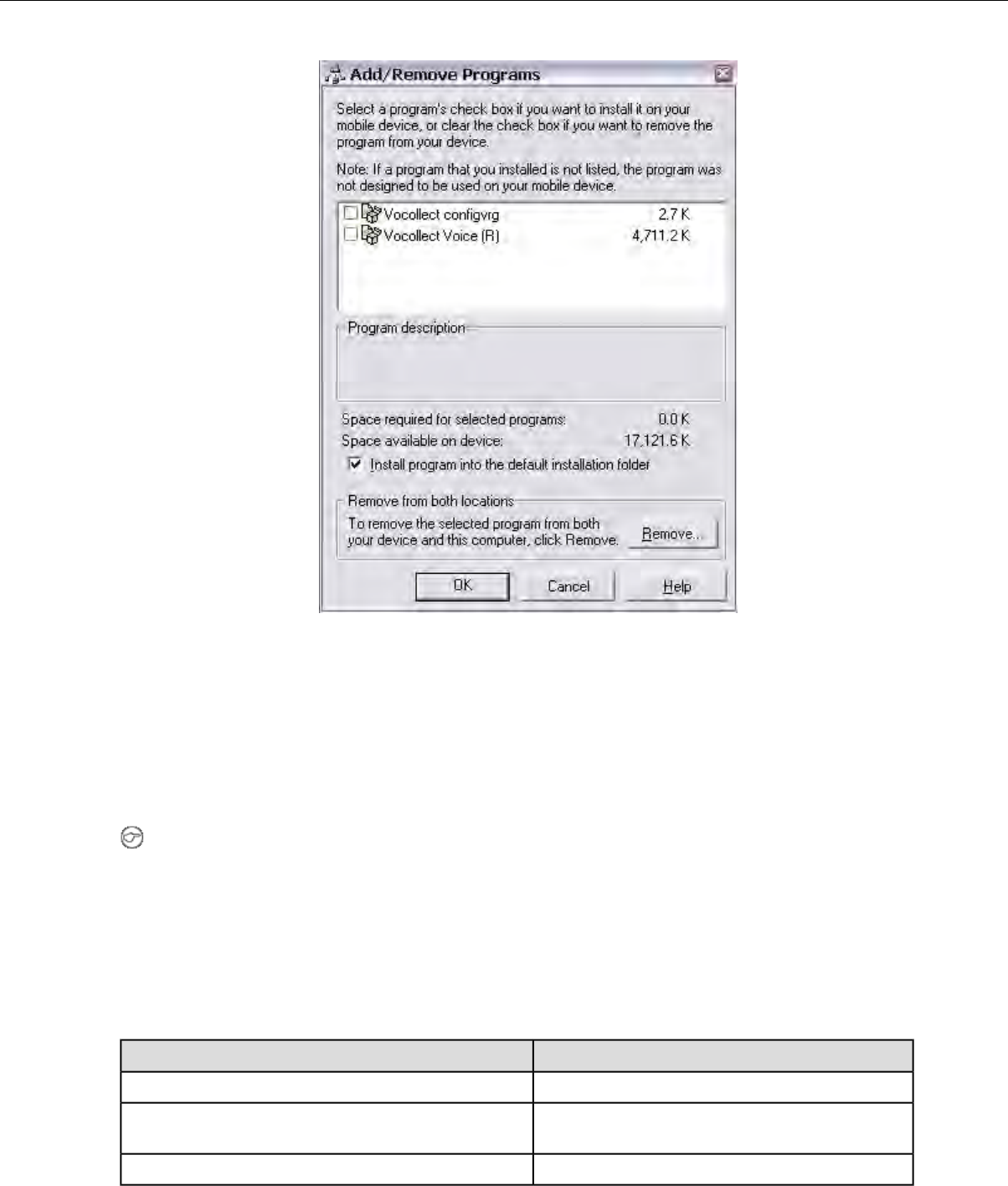
Figure 163: CE Application Manager Window
4. Check both the Vocollect configvrg and Vocollect Voice checkboxes. Be sure the Install program
into the default installation folder checkbox is checked.
5. Click OK.
Repeat these steps for each device onto which you want to install Vocollect Voice.
Installing Vocollect Voice 1.3 and Later Using Other Synchronization Software
Note: This process is required only for initial configuration. Modifications to the device profile can
be downloaded using VoiceConsole when a device is connected to the VoiceConsole application.
1. Create an appropriately named folder, either on your desktop or in a location that is easy to access.
2. Place the Vocollect Voice DVD into your DVD drive and open its folder.
3. Select all files (executables, .cab, .ddf, and .vrg files) and copy them to the folder you created.
4. Open the folder that you created, that contains the .cab file and executables.
5. Use the synchronization tool to place the .cab file onto the handheld device and extract it.
6. Place the config.vrg into the appropriate folder:
DirectoryDevice
\Flash Disk\Psion devices running Windows CE
\Storage\Psion devices running Windows Mobile (VVH 1.3 and
earlier)
\System\VocollectVoice\Honeywell LXE
Confidential: For informational use by Vocollect Resellers and customers only
210 | Vocollect Hardware Documentation
DirectoryDevice
\Application\VocollectVoice\Motorola
\Vocollect\VocollectVoice\Intermec
7. In VoiceConsole, create a device profile with the VoiceConsole URL.
8. Export the profile from VoiceConsole to a location that is easy to access. VoiceConsole automatically
assigns a .vrg extension to the exported device profile.
9. Browse to the location to which you exported the device profile.
10. Rename the file config.vrg.
Note: The device profile you created in VoiceConsole will be retained in VoiceConsole with its
original name.
11. Place the config.vrg file into the appropriate directory on your device.
12. Restart the voice application for the new device profile to be detected and used.
Installing Vocollect Voice Using Other Synchronization Software
Note: This process is required only for initial configuration. Modifications to the device profile can
be downloaded using VoiceConsole when a device is connected to the VoiceConsole application.
1. Create an appropriately named folder, either on your desktop or in a location that is easy to access.
2. Place the Vocollect Voice DVD into your DVD drive and open its folder.
3. Select all files (executables, .cab, .ddf, and .vrg files) and copy them to the folder you created.
4. Open the folder that you created, that contains the .cab files and executables, and find the .cab file
for your locale (for example, XXXXXXXX_VVoiceCabInstall_en_US.CAB).
5. Use the synchronization tool to place the .cab file onto the handheld device and extract it.
6. Place the config.vrg into the appropriate folder:
DirectoryDevice
\Flash Disk\Psion devices running Windows CE
\Storage\Psion devices running Windows Mobile (VVH 1.3 and
earlier)
\System\VocollectVoice\Honeywell LXE
\Application\VocollectVoice\Motorola
\Vocollect\VocollectVoice\Intermec
7. In VoiceConsole, create a device profile with the VoiceConsole URL.
8. Export the profile from VoiceConsole to a location that is easy to access. VoiceConsole automatically
assigns a .vrg extension to the exported device profile.
9. Browse to the location to which you exported the device profile.
10. Rename the file config.vrg.
Note: The device profile you created in VoiceConsole will be retained in VoiceConsole with its
original name.
11. Place the config.vrg file into the appropriate directory on your device.
12. Restart the voice application for the new device profile to be detected and used.
Confidential: For informational use by Vocollect Resellers and customers only
Vocollect Voice on Handheld Devices | 211

Updating Configuration Files Using VoiceConsole
1. Place the device into maintenance mode by either placing it in a cradle or selecting Maintenance
Mode in the Tools menu.
2. Select or create the device profile in VoiceConsole.
3. Follow the procedures in VoiceConsole for loading the profile.
4. Reload any previously loaded Vocollect VoiceApplication and operator files.
Updating Configuration Files Using ActiveSync
1. In VoiceConsole, create a device profile with the VoiceConsole URL.
2. Export the profile from VoiceConsole to a location that is easy to remember and easy to access.
3. Open the Vocollect Voice DVD.
4. Place the config.vrg file into the appropriate directory on your device.
5. Drag the device profile (profilename.vrg) onto the appropriate executable.
The executable loads the config.vrg file onto the handheld device.
Updating Configuration Files Using Other Synchronization Tools
1. In VoiceConsole, create a device profile with the VoiceConsole URL.
2. Export the profile from VoiceConsole to a location that is easy to remember and easy to access.
3. Browse to the location to where you exporting the device profile.
4. Rename the file config.vrg.
5. Use the synchronization tool to place the config.vrg file you created into the appropriate directory on
your device. See Installing Vocollect Voice 2.0 and Later Using Other Synchronization Software for
a table of devices and directories.
Setting the Default Voice on the Device
The English voice (en_US_1) is installed on the device when you install this version of Vocollect Voice.
If operators require a different voice, you must add the specific voice module(s) to the device.
1. After installing Vocollect Voice, ensure the device has enough space in flash memory to accommodate
the voice(s) you want to install by comparing the free space in flash to the size of the voice(s).
2. Place the folder containing the voice module you want accessible (located on the Vocollect Voice DVD)
on the device in a folder in the flash memory. Note: Some voices may not be supported on your device.
Please see the release notes for your version of Vocollect Voice for a list of supported voices.
Note: Voice module folders must be kept in a location other than the Vocollect Voice directory
to prevent a failure when changing voices on the device.
Note: The voice module(s) must be placed in a folder in flash. Do not put the folder in RAM. If
placed in RAM, the voice modules will be gone on the next device reboot.
Confidential: For informational use by Vocollect Resellers and customers only
212 | Vocollect Hardware Documentation

Voice Module FolderLanguage and Voice Number
en_US_1English (United States) 1
en_US_6English (United States) 6
nl_BE_1Dutch (Belgium) 1
nl_BE_3Dutch (Belgium) 3
nl_BE_6Dutch (Belgium) 6
pt_BR_3Portuguese (Brazil) 3
pt_BR_6Portuguese (Brazil) 6
en_GB_2English (Great Britain) 2
en_GB_3English (Great Britain) 3
en_GB_6English (Great Britain) 6
fr_CA_2French (Canada) 2
fr_CA_6French (Canada) 6
cs_CZ_3Czech (Czech Republic) 3
cs_CZ_6Czech (Czech Republic) 6
da_DK_3Danish (Denmark) 3
da_DK_6Danish (Denmark) 6
fi_FI_2Finnish (Finland) 2
fi_FI_6Finnish (Finland) 6
fr_FR_1French (France) 1
fr_FR_3fFrench (France) 3f
fr_FR_3mFrench (France) 3m
fr_FR_6French (France) 6
de_DE_1German (Germany) 1
de_DE_6German (Germany) 6
el_GR_3Greek (Greece) 3
el_GR_6Greek (Greece) 6
hu_HU_6Hungarian (Hungary) 6
it_IT_2Italian (Italy) 2
it_IT_6Italian (Italy) 6
es_MX_2Spanish (Mexico) 2
es_MX_6Spanish (Mexico) 6
nl_NL_3Dutch (Netherlands) 3
nl_NL_6Dutch (Netherlands) 6
no_NO_3Norwegian (Norway) 3
Confidential: For informational use by Vocollect Resellers and customers only
Vocollect Voice on Handheld Devices | 213
Voice Module FolderLanguage and Voice Number
no_NO_6Norwegian (Norway) 6
pl_PL_3Polish (Poland) 3
pl_PL_6Polish (Poland) 6
pt_PT_3Portuguese (Portugal) 3
pt_PT_6Portuguese (Portugal) 6
ro_RO_6Romanian (Romania) 6
ru_RU_3Russian (Russia) 3
ru_RU_6Russian (Russia) 6
sk_SK_6Slovak (Slovakia) 6
es_ES_1Spanish (Spain) 1
es_ES_6Spanish (Spain) 6
sv_SE_1Swedish (Sweden)1
sv_SE_3Swedish (Sweden) 3
sv_SE_6Swedish (Sweden) 6
tr_TR_6Turkish (Turkey) 6
3. Place the following parameters under the
[HKEY_LOCAL_MACHINE\Vocollect\CONFIG_PARAMS\DIAG_FILE] registry setting in the
config.vrg file:
• "VVHModuleLocation"="path to folder you created in step 2"
• "defaultVoice"="voice name language code"
Upon startup, Vocollect Voice searches the folder for voice modules and begins with the specified
voice. See VoiceConsole Online Help or Release Notes for Vocollect Voice for your device for more
information on these parameters.
Note: If the default voice on the device needs to be changed, repeat this process but with the
new voice name language code set in the defaultVoice parameter.
Starting Vocollect Voice
Before you turn the voice engine on, make sure that there is a charged battery connected to the device
and that you have put on a properly connected headset.
Note: For Intermec devices only: To create more available memory, Vocollect recommends
closing or uninstalling applications that are not in use prior to running Vocollect Voice on Intermec
devices. The following programs must remain on Intermec CK3 devices to run Vocollect Voice, but
these programs are not required for Intermec 70-Series devices:
• Data Collection and Intermec Settings
• Bluetooth (only when Bluetooth devices are in use)
• IDLRuntime
• Power Profiler
Confidential: For informational use by Vocollect Resellers and customers only
214 | Vocollect Hardware Documentation

• Additional Files (Intermec specific files)
See the device's documentation for information on how to uninstall or remove programs from the device.
Note: For Intermec devices, the application will not appear in the Start menu upon installation.
The first time you launch the application, browse to Start >Programs , and select the Vocollect
Voice application. The application will now appear in the Start menu.
1. Tap Start on the device screen's main menu.
The Vocollect Voice window displays.
2. On the drop-down menu, tap the Vocollect Voice symbol .
The Vocollect Voice version number and your device ID display beneath the logo.
3. Tap the play/pause button on the device screen.
The voice engine says "Current operator is Operator Name. Please keep quiet for a few seconds." After
a pause, the voice engine says "Please say zero" to initiate the noise sample.
4. Complete the noise sample.
After a brief pause, the voice engine says "Please wait." After another pause, the voice engine begins
asking questions or providing instructions according to your site's installation.
Exiting Vocollect Voice
1. Tap Tools >Exit or Start >Exit on the device screen.
A message displays, asking if you wish to exit the application.
2. Tap Yes to exit the application.
Caution: You must exit the voice application before you change the battery (if necessary) or you
will lose the data that you have collected. Do not remove the battery until the status indicator is
off. Tap No to return to the voice application.
Note: You should not exit Vocollect Voice if the status indicator is blinking red, unless it has
been blinking red for several minutes. If a device is turned off when the status indicator is blinking
red, the voice engine may not be ready to use when it is turned back on.
Template Conversion Tool
This is a tool for converting templates created for use on Vocollect hardware (T-Series devices) into
templates for use on handheld devices. To convert templates, you must edit specific variables in the
batch file, and then run the batch file to perform the conversion, by performing the following steps:
1. Locate and open the ConvertTxTemplates folder on your Vocollect Voice DVD. You must have this
folder and its files in the same directory or path of your version of Java.
2. Right-click on the file _ConvertTxTemplatesForIntermec.bat in the folder, and select to open the
file in a text editor.
3. Enter details specific to your instance of VoiceConsole in the fields mentioned below. Specify these
details in the first instance of these fields in the batch file, which is directly below the comment
"Specify the host name (or IP address) of the VoiceConsole installation and the port through which
it can be accessed."
Confidential: For informational use by Vocollect Resellers and customers only
Vocollect Voice on Handheld Devices | 215

•set VC_HOST_NAME_OR_IP: Specifies the host computer on which VoiceConsole is running.
The VoiceConsole host computer name appears in the VoiceConsole address bar at the beginning
of the URL. Example: http://EXAMPLE_HOST_NAME:9080/VoiceConsole/
•set VC_PORTNUM: Port on which VoiceConsole is listening.
•set VC_USERNAME: Username required to log into VoiceConsole.
•set VC_PASSWORD: Password required to log into VoiceConsole.
•If the site name is not Default, change rem set VC_SITENAME=--sitename Default to set
VC_SITENAME=--sitename.
4. Specify the operators.
a) If using VoiceConsole 2.4 or earlier, specify the range of operator primary keys (PK) that should
be imported to convert. To find the PK for an operator, go to the Operator View in VoiceConsole,
and click on the operator. The PK appears in the address bar at the end of the URL.
Example: http://10.0.14.183:9080/VoiceConsole/ModifyOperatorPropertiesStart.do?pk=769
b) If using VoiceConsole 3.0 or later, specify the range of operator ids that should be imported to
convert. To find the operator id for an operator, go to the View Operator page in VoiceConsole for
the operator. The operator id appears in the address bar at the end of the URL.
Example: http://10.60.0.201:9080/VoiceConsole/core/operator/view.action?operatorId=-67
c) Enter details in the following fields:
•set MIN_OPER_PK: Identifies the minimum operator PK/operator id to be converted.
•set MAX_OPER_PK: Identifies the maximum operator PK/operator id to be converted.
Note: If only converting one operator, you must specify the same value for minimum and
maximum.
5. Save your work.
6. Close the text editor.
7. Run the file _ConvertTxTemplates.bat.
Your templates convert and are ready for use.
8. To confirm templates have been converted, select to manage the operator's templates in VoiceConsole.
If the conversion was successful, there will be two sets of templates, each with a different version,
for the operator's template you converted.
Loading an Operator's Templates onto a Handheld Device
You need a device with a charged battery, headset, and any other equipment (belt, bar code reader) you
are going to use. You must be within radio range. Make sure the device is on or sleeping. The LED
indicator should be either solid green or blinking green (A500, T5-series and T2-series) or solid green
(T1).
1. On the device screen, tap the operator button.
The voice engine says "Current operator is operator name. Select menu item."
2. Tap the + button or — button until the voice engine says, "Change operator." Then, press the operator
button.
The voice engine says "Please wait." It may take a few moments for the voice engine to retrieve a list
of operators and teams.
3. Wait for the voice engine to say. "Select team."
• If the voice engine says " . . . Change operator ," skip to step 6.
Confidential: For informational use by Vocollect Resellers and customers only
216 | Vocollect Hardware Documentation

4. Tap the + button or — button to scroll through the list of operator teams until you hear the name of
a team to which you belong.
5. Tap the operator button.
The voice engine says, "Please wait." It may take a few moments for the voice engine to retrieve a
list of operators who belong to the selected team. The voice engine then says, "Current operator is
operator name. Select new operator."
6. Tap the + button or — button to scroll through the list of available operator names until you hear
your name.
• If you do not hear your name, tap the yellow play/pause button to cancel this operation and start
over from step 2. When selecting a team in step 3, choose the "All Operators" team.
• Consult with your supervisor if you are not listed in the "All Operators" team.
7. Tap the operator button.
The voice engine says, "Loading operator." The voice engine then loads your templates. While your
templates are loading, you will hear a beep periodically and the status indicator on the device screen
will blink red. Once it has loaded your templates, the voice engine says, "Current operator is operator
name. Good night" and goes to sleep.
8. Tap the yellow play/pause button on the device screen to restart the voice engine and to begin work.
Changing the Voice on a Handheld Device
A device can store several voices, depending on the memory available on the device. By selecting a new
voice module, operators can change the voice language or voice quality that is spoken by the device
without having to ActiveSync, without contacting VoiceConsole, and without reinstalling Vocollect Voice.
This feature is helpful for multilingual sites and for sites whose operators prefer different sounding
voices.
Note: This feature is supported on Vocollect Voice 2.0 and newer.
Enabling the Ability to Change Voices
1. After installing Vocollect Voice, ensure the device has enough space in flash memory to accommodate
the voice(s) you want to install by comparing the free space in flash to the size of the voice(s).
2. Place the folder containing the voice module you want accessible (located on the Vocollect Voice DVD)
on the device in a folder in the flash memory. Note: Some voices may not be supported on your device.
Please see the release notes for your version of Vocollect Voice for a list of supported voices. See Setting
the Default Voice on the Device for a list of languages and voice module folders.
Note: Voice module folders must be kept in a location other than the Vocollect Voice directory
to prevent a failure when changing voices on the device.
Note: The voice module(s) must be placed in a folder in flash. Do not put the folder in RAM. If
placed in RAM, the voice modules will be gone on the next device reboot.
3. Place the following parameter under the
[HKEY_LOCAL_MACHINE\Vocollect\CONFIG_PARAMS\DIAG_FILE] registry setting in the
config.vrg file:
"enableVoiceSwitchMenu"="1"
Note: Ensure the VVHModuleLocation parameter is set to the correct location (\VoiceModules)
of the voice module(s).
Confidential: For informational use by Vocollect Resellers and customers only
Vocollect Voice on Handheld Devices | 217

See VoiceConsole Online Help or Release Notes for Vocollect VoiceClient 2.0 for your device for more
information on parameters.
Changing Voice Modules
Note: The device should be in the sleep state before you attempt to change the voice module.
1. On the device, select Tools | Change Voice Module.
The Change Voice Module box opens.
2. Select a voice. Note: Some voices may not be supported on your device. Please see the release notes
for your version of Vocollect Voice for a list of supported voices. See Setting the Default Voice on the
Device for a list of languages and voice module folders.
Note: Voice module folders must be kept in a location other than the Vocollect Voice directory
to prevent a failure when changing voices on the device.
Note: The voice module(s) must be placed in a folder in flash. Do not put the folder in RAM. If
placed in RAM, the voice modules will be gone on the next device reboot.
3. Select OK or press Enter.
Vocollect Voice restarts with the new language and/or new voice type.
Vocollect Voice: Warning Messages
Vocollect Voice displays the following screen messages, when appropriate. You also may hear warning
messages through your headset.
License Not Available
Application cannot obtain valid license from VoiceConsole. Please move to a better radio coverage area
or see your supervisor.
This message indicates your device cannot obtain a valid license. Move to an area that you know has
good radio coverage and try again.
Low Battery
Your battery is critically low. To prevent loss of data, the voice application has been stopped, and all
data has been safely stored. Please change battery or cradle device now.
This message is issued when the device battery's charge drops to a critically low level. The voice application
shuts down; all data is stored, but you must change the battery to continue working or cradle the device.
Critical Startup Error
Vocollect Voice could not start. The following critical modules were not found: * Vocollect VoiceApplication
* Vocollect Licensing Vocollect Voice will now exit.
This message is issued if the voice application cannot find information it needs to run. See your supervisor
if you receive this message.
Application Exit with Data Pending
Application data has not been sent. If you exit now, the data will be sent next time you run Vocollect
Voice. Are you sure you want to exit Vocollect Voice?
Confidential: For informational use by Vocollect Resellers and customers only
218 | Vocollect Hardware Documentation

You will see this message if you tap Tools >Exit before the voice application has finished sending data
to the host computer. You will see Yes and No buttons. If you tap No, the voice application will finish
sending data. If you tap Yes, data will be preserved, and it will be sent when the voice application is
started again.
Headset Pairing
No wireless headset found.
This message is issued when the device is in pairing mode if it cannot find an available SRX Wireless
Headset. Begin the pairing procedure again, making sure you hold your headset and device so they touch
each other.
About Maintenance Mode
A handheld device running Vocollect Voice automatically enters maintenance mode when it is placed in
a cradle and the charging state is detected.
You also can place a device into maintenance mode by tapping Tools >Maintenance Mode on the
device screen.
You cannot perform voice tasks while the device is in maintenance mode.
The device remains in maintenance mode until it is removed from the cradle or until you tap Exit
Maintenance Mode on the device screen.
Note: The status indicator is not visible when the voice application is in maintenance mode. In
most cases, you must wake up the voice application when you exit maintenance mode.
Confidential: For informational use by Vocollect Resellers and customers only
Vocollect Voice on Handheld Devices | 219
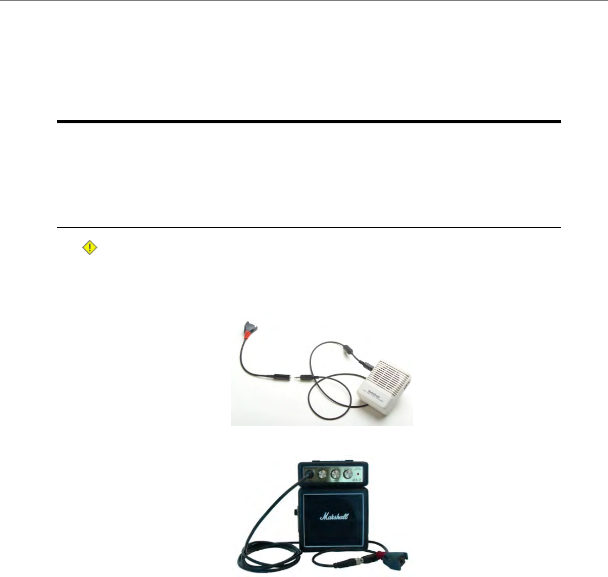
Chapter 12
Listening Kits
When training new operators, you may want to listen in on their progress working with the voice system.
Vocollect recommends specific listening kits for this purpose.
Wired Listening Kits
Caution: Vocollect strongly recommends the use of only approved listening systems sold by Vocollect.
If you choose to use a listening system that is not approved by Vocollect, Vocollect requires that the
listening system is independently powered through its own source (such as a battery) and has an
input impedance greater than or equal to 2K ohms. Vocollect is not responsible for equipment damage
that may be caused by listening systems not sold by Vocollect.
Figure 164: Radio Shack Wired Listening Kit
Figure 165: Marshall Demonstration Wired Listening Kit
• The wired listening kit connects to Talkman devices or handheld devices and allows a number of
people, such as trainers or supervisors, to listen to the conversation between an operator and a
Talkman device or handheld device.
• The Vocollect audio adapter cable with the red connector can be used with Talkman devices.
• A device-specific adapter training cable (also referred to as a "Y" or splitter cable) must be used with
third-party handheld devices.
• For more information, consult the user manual provided with your listening kit.
Confidential: For informational use by Vocollect Resellers and customers only
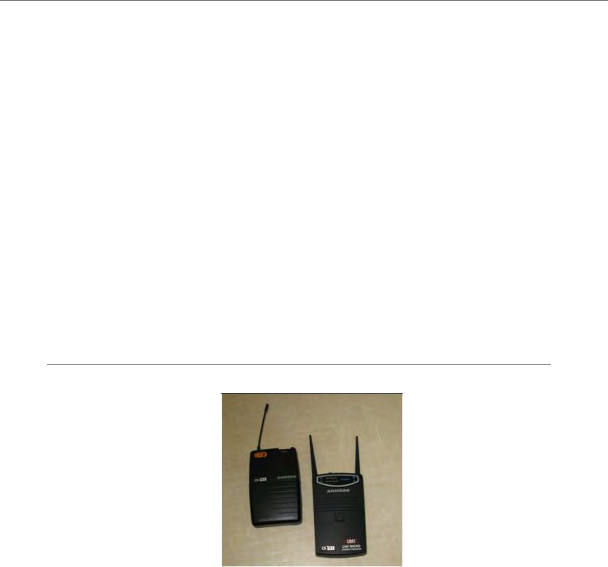
Monitoring Audio on a Talkman Device
1. Connect the 3.5 mm jack on the inline adapter training cable to the input jack on your listening
system.
• Be sure to use the training cable with red connection port, unless that port on the Talkman device
is already being used by a visual training device.
• If you are using a visual training device, use the headset training cable (AD-300-1) connected to
the yellow port.
2. Connect the other end of the training cable to the matching port on the Talkman device.
3. Power on the wired listening kit and begin working.
Monitor Audio on a Handheld Device
1. Connect the 3.5 mm jack on the inline adapter training cable to the input jack on your listening
system. Be sure to use the correct adapter cable for your device.
2. Connect the inline adapter training cable to your Vocollect SR-Series headset.
3. Connect the other end of the inline adapter training cable to your handheld device.
4. Power on the wired listening kit and begin working.
Samson Wireless Listening Systems (TR-605-x)
The Samson TR-605-x wireless listening kit replaces the TR-604-x kit which has been discontinued.
Figure 166: TR-605-x
• The wireless listening system allows trainers, administrators, or other operators to remotely listen
to the conversation between an operator and a Talkman wearable computer or handheld device.
•The wireless listening system consists of a transmitting radio and a receiving radio which communicate
with each other over a particular radio channel. This system can be used to monitor several operators
by setting each transmitting radio to a different channel and then changing the channel on the
receiving radio to that of the transmitter you wish to monitor.
Confidential: For informational use by Vocollect Resellers and customers only
222 | Vocollect Hardware Documentation
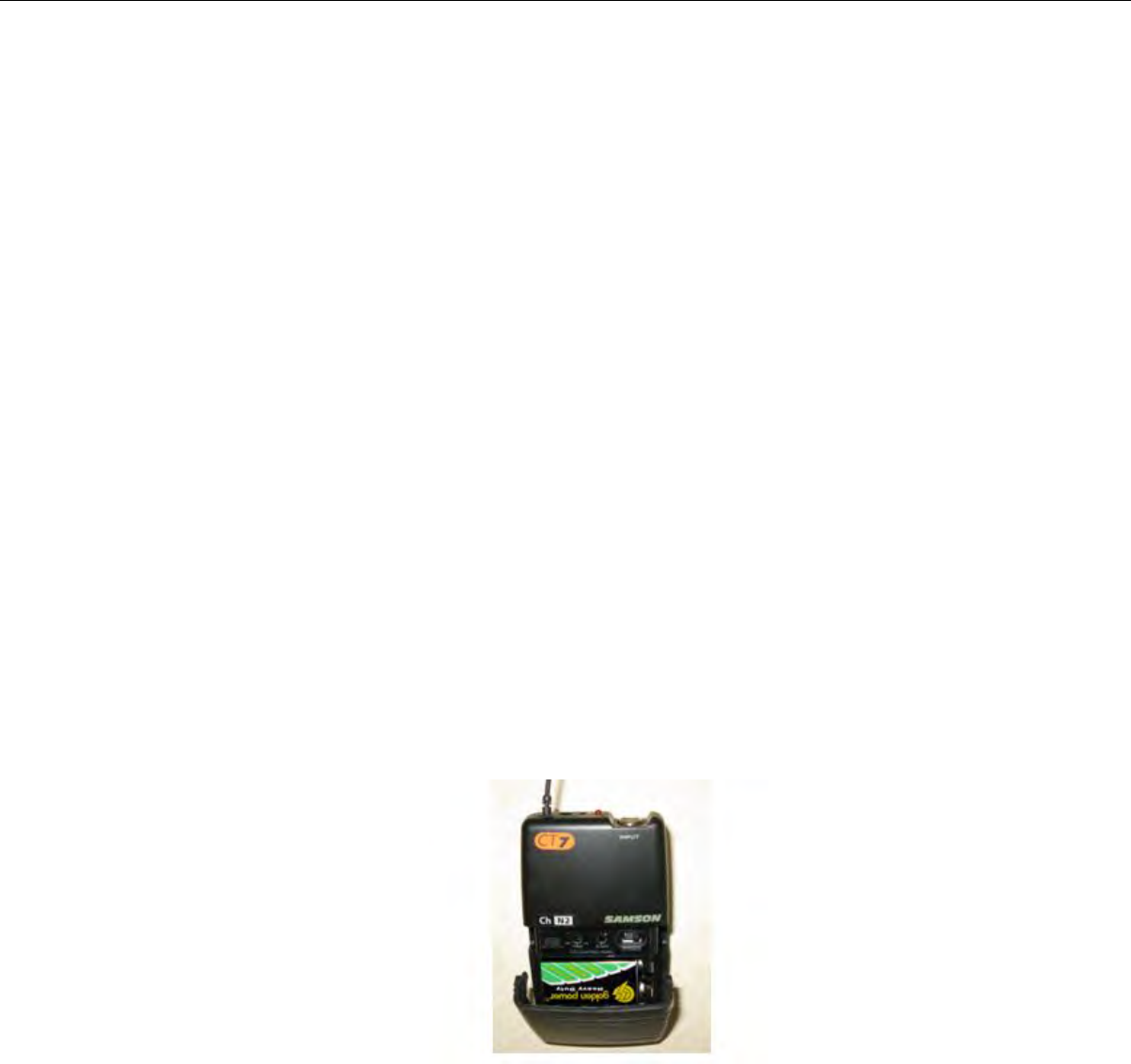
Using the Samson Wireless Listening System
For best performance, attach listening devices to the red port of your Talkman device. If the red port is
unavailable, or if you are using a handheld device, an inline adapter training cable, or "Y" cable, attached
to the yellow port may be used. When using the "Y" cable, be sure to connect both a Vocollect headset
and the listening system transmitter because the headset's performance is influenced by gain and
headphones level adjustments.
You need the following items:
• Samson listening kits (TR-605-x) with both radios configured to the same channel setting. Each
listening system contains the following items:
• Receiver
• Transmitter
• Plastic screwdriver
• Headphones with 3.5 mm jack
• Batteries (2 9V for TR-605-x)
• Vocollect audio adapter cable
• If you are using a Talkman A500/T5 with a wired barcode reader, you will need the TR-603-102 "Y"
adapter cable which connects a scanner and a listening kit transmitter via the red port on the A500/T5
device.
•If you are using a handheld device, you will need the AD-300-1 inline "Y" adapter training cable which
provides a connection for a wired Vocollect headset and an audio output connection to go to the
listening kit transmitter.
• Talkman device or handheld device
• Vocollect SR-Series headset
Setting up the Transmitting Radio
Figure 167: Transmitting Radio TR-605-x
The transmitting radio is set up as a dedicated transmitter and is connected to the operator's Talkman
device or handheld device.
1. Insert a battery into the transmitting radio. (TR-605-x transmitters are labeled UHF BELTPACK
TRANSMITTER on the bottom front)
2. Connect the Vocollect audio adapter cable to the matching port on the operator's Talkman device or
handheld device.
• If you are using a Talkman device, make sure to connect the audio adapter cable to the red port
on the Talkman device.
Confidential: For informational use by Vocollect Resellers and customers only
Listening Kits | 223
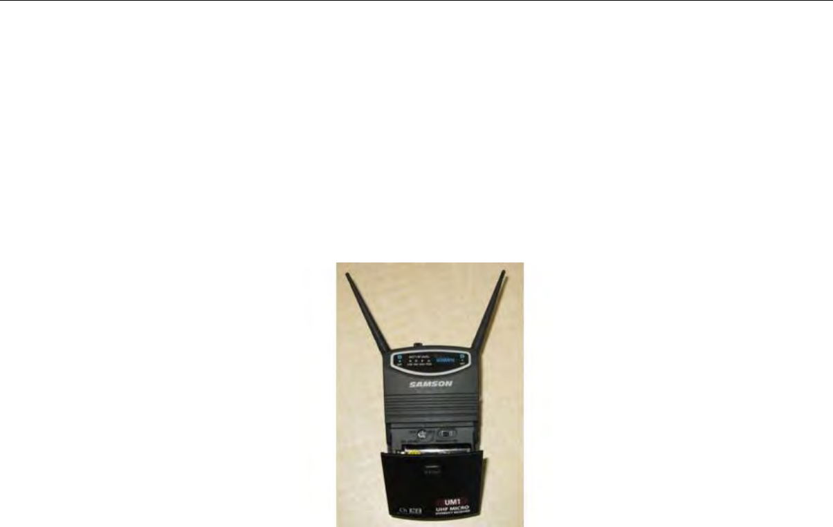
• If you are using a handheld device, make sure to use the correct audio adapter training cable for
your device.
3. Insert the 3.5mm male jack into the INPUT connector on the Samson transmitter.
4. Power on the transmitting radio.
5. Assure that output is enabled with the Mute/Audio switch set to the connect position.
• For TR-605-x units, slide the Audio switch to ON.
Setting up the Receiving Radio
The receiving radio is set up as a dedicated receiver for use by a trainer.
Figure 168: Receiving Radio TR-605-x
1. Insert a battery into the grey receiving radio.
2. Connect a headset or powered speaker to the receiver's headphone jack.
3. Power on the receiving radio.
4. If needed adjust output level (indicated by #1 in yellow above).
Adjusting the Listening System for Optimum Performance
1. Press the Plus button on your Talkman device or handheld device until the volume reaches its
maximum setting.
You will hear “This is loudest”.
2. On the transmitting radio, locate the adjustment indicated as #1 on the transmitting unit. Align a
small screwdriver tip with the slot in the control screw and use gentle pressure to fully rotate the
control screw counterclockwise to set the gain to its minimum setting. Use extra care if you use a
metal screwdriver as metal may damage the gain controls.
3. On the receiving radio, locate the control marked #1. Gently rotate the control screw counterclockwise
to set the headphone volume to its minimum setting.
4. On the gray receiving radio, turn the Phones Level setting back clockwise approximately 20 degrees.
5. Power on both listening system radios.
6. Put on the gray receiving radio's headphones or powered speaker.
7. Press the Plus or Minus buttons on the Talkman device or handheld device as you adjust the receiving
radio's headset volume to the maximum desired level.
8. Make additional adjustments:
Confidential: For informational use by Vocollect Resellers and customers only
224 | Vocollect Hardware Documentation
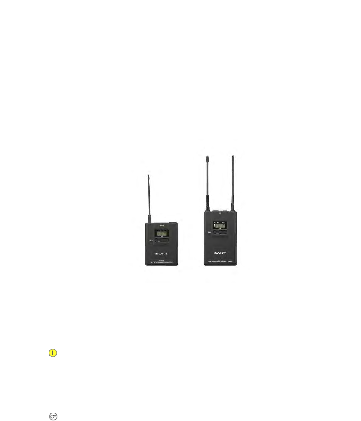
• If the audio sounds distorted, readjust the Phones Level control on the gray receiving radio by
rotating the control screw slightly counterclockwise while pressing the Plus button on your device.
• If the volume is too low, even with the headphones set to their maximum level, adjust the gain on
the black transmitting radio by rotating the Gain control screw slightly clockwise while pressing
the Plus button on your device.
If you are using an inline adapter training cable connected to a handheld device, it is likely you will
have to readjust the gain.
9. Once the wireless listening system settings have been adjusted to maximum volume without distortion,
use the volume control on the headphones, powered speaker, or the Plus and Minus buttons to lower
the device's volume.
Sony Wireless Listening Systems (UTX-B2 and URX-P2)
Figure 169: Sony®UTX-B2 and URX-P2
• The wireless listening system allows trainers, administrators, or other operators to remotely listen
to the conversation between an operator and a Talkman wearable computer or handheld device.
•The wireless listening system consists of a transmitting radio and a receiving radio which communicate
with each other over a particular radio channel. This system can be used to monitor several operators
by setting each transmitting radio to a different channel and then changing the channel on the
receiving radio to that of the transmitter you wish to monitor.
Important: Ensure that you do the following before using the listening system:
•Set the transmitter's Line/Mic switch to Line
•Plug the monitoring headphones into the Monitor port on the receiver
• Turn down the headset's volume before putting it on
Setting up the Receiving Radio
Note: The receiver is labeled UHF Synthesized Diversity Tuner.
Confidential: For informational use by Vocollect Resellers and customers only
Listening Kits | 225

1. Insert batteries into the receiver.
2. Turn on the receiver.
3. Press and hold the Set button until the display flashes.
4. Press the Set button repeatedly to scroll through the settings. Stop when you reach Scan.
5. Press the +button to scan for a clear channel.
The channel bank will be displayed.
6. After a clear channel is found, and no other buttons are pressed, the display will blink for another
15 seconds then stop. This indicates the channel selection was accepted.
7. You will see two digits followed by the channel bank. Use the channel bank digits to set up the
transmitter.
For example, if you see 04.3101, use 3101 to set up the transmitter.
8. Follow the steps to set up the transmitter.
Setting Up the Transmitting Radio
1. Insert batteries into the transmitter. For more information, see the manufacturer's documentation.
2. Set the input switch on the top of the transmitter to Line.
3. Press and hold the Set button and turn on the transmitter.
4. Repeatedly press the set button until you locate the channel bank number displayed on the receiver.
5. Power the transmitter off to commit the changes to memory.
6. Turn on the transmitter.
It will be set to the frequency that you chose.
7. Verify that the tranmitter's setting matches the frequency or channel bank selected on the receiver.
Connecting the Sony Wireless Listening Kit to a Talkman Device
1. Connect the Talkman device to the transmitter using a Vocollect cable.
2. Connect a headset to the receiver's Monitor port.
Part Numbers: Listening Kits
Vocollect Part NumberPart Description
TR-605-xSamson Wireless Listening Kit, Transmitter and Receiver, CH. x, V2
(x=1-6)
TR-606-1Sony Wireless Listening Kit, Transmitter (UTX-B2) and Receiver
(URX-P2), 566-590 MHz
TR-603-101Audio adapter cable, Wireless Listening Kit, 1/8" or 3.5mm male (for
Sony Wireless Listening System)
TR-603-102Audio adapter cable, Wireless Listening Kit, 1/8" or 3.5mm male
TR-604-101Audio adapter cable, Wireless Listening Kit, 1/32" or 2.5mm male
(Worldwide)
AD-300-1Adapter, Audio Splitter Cable for training to Vocollect Headsets
Choosing Cables for Your Training Configurations
Confidential: For informational use by Vocollect Resellers and customers only
226 | Vocollect Hardware Documentation

Cable ConfigurationsScannerHeadsetDevice
TR-603-102 connects:Talkman
A500/T5 •• wiredwired (connects to
A500/T5 YELLOW
port), or
• scanner
• wired listening kit or transmitter
for wireless kit• wireless
to A500/T5 RED port
TR-603-101 or TR-604-101 connects:Talkman
A500/T5 •• wireless, orwired (connects to
A500/T5 YELLOW
port)
• wired listening kit or transmitter
for wireless kit
• no scanner
to A500/T5 RED port
TR-603-101 or TR-604-101 connects:Talkman T2x •• wired (connects to
T2x BLUE port),
wired (connects to
T2x YELLOW port) • wired listening kit or transmitter
for wireless kit
• wireless (T2x
Bluetooth Serial to T2x RED port
Adapter connects to
BLUE port), or
• no scanner
AD-300-1 connects:Third Party
Device •• built-in,wired, or
• headset (SR20 or equivalent)
• •wireless wireless, or
• wired listening kit or transmitter
for wireless kit
• no scanner
to device YELLOW port or headset
port
Confidential: For informational use by Vocollect Resellers and customers only
Listening Kits | 227

Chapter 13
Troubleshooting Equipment Problems
Sometimes you will not see an LED indicator change or hear an error message, but will see some other
sign of trouble. Find the description below that most accurately describes what you see. Follow the steps
in sequence until the issue is resolved; start with the first option and see if that solves your problem
before moving on to the second. If none of the listed steps resolve the problem, contact Vocollect to send
the equipment back for repair or to speak with a support representative.
I Can't Hear Anything Through the Headset
1. Make sure the device has a fully charged battery.
2. Make sure the headset is properly connected to the device.
3. Try the headset on a device that is not having problems.
4. Try a different headset on the device with the problem.
5. Turn the device off and then back on again.
6. Reboot the device.
7. If you are using an SRX headset, make sure your headset is paired with your device.
8. If the headset is broken, send it back to Vocollect for repair.
My Bar Code Reader Won't Scan
1. Make sure the bar code reader is plugged into the device properly.
2. Try a different bar code reader.
3. Try connecting the bar code reader to a different device.
4. If the bar code reader is damaged, send it back to Vocollect for repair.
5. Verify that the task package contains the correct bar code configurations.
My Headset Won't Stay On
1. Make sure the headset wire is clipped properly to your clothing.
2. Make sure that you are following the proper procedure for wearing a headset.
3. If you are using an SRX headset, make sure the headband strap is positioned properly across the
back of your head.
Confidential: For informational use by Vocollect Resellers and customers only

The Device Beeps Every Few Seconds
1. Wait for a few minutes. The voice engine may just be communicating with the host.
2. If the beeping continues beyond a few minutes, see the administrator.
3. The administrator can check device logs in VoiceConsole to attempt to diagnose the problem.
The Device Will Not Load a Voice Application
1. Try loading the voice application again. See the VoiceConsole online help for instructions.
2. Make sure the device is properly placed in a charger.
3. Check for error messages in VoiceConsole.
4. Make sure you are in radio range of an access point.
5. Make sure the device's ChangeTaskEnabled parameter is set to 1.
6. Reboot the device.
7. Put the device in debug mode to look for a clue to the problem.
The Device Will Not Load an Operator Template
1. Make sure you are loading the operator properly.
2. Make sure the operator has created a voice template.
3. Make sure you are in radio range.
4. Reboot the device.
The Device Does Not Respond to Button Presses
1. Make sure the device has a fully charged battery.
2. Reboot the device.
3. Send the device back to Vocollect for repair.
The Device Will Not Turn On
1. Make sure the battery is properly seated on the device.
2. Make sure the device has a fully charged battery.
3. Send the device back to Vocollect for repair.
Confidential: For informational use by Vocollect Resellers and customers only
230 | Vocollect Hardware Documentation

The Device Keeps Shutting Off
1. Change the battery.
2. Make sure you are placing the battery on correctly.
3. Check the battery compartment on the device to make sure it is not damaged. If it is damaged, send
the device back to Vocollect for repair.
4. Check VoiceConsole for crash dump files with this device's specific serial number.
Troubleshooting Guide for the Talkman A500/T5 Battery Charger
This topic describes some of the issues that can arise with the Talkman A500/T5 Battery Charger, their causes
and how you can verify the cause.
If the steps don't
work...
Try these steps...If this occurs...
Have the charger
replaced or repaired.
Check to see if the
contacts on the device
A device without a
battery will not power up
This is not able to be
corrected by a customer.
and charger are clean. If
not, follow cleaning
procedures and retry.
when placed in a
particular charger slot,
but will power up in
other slots in either this
Have the charger
replaced or repaired.
Examine the charger slot
to determine whether
charger or another
charger.
This is not able to be
corrected by a customer.
there is a mechanical
alignment issue. There
should be little or no
space between the front
two plastic pegs and the
edge of the pocket. If an
item like a credit-card
will fit in this space,
there may be an
alignment issue.
Have the charger
replaced or repaired.
Verify that the device is
properly seated in the
This is not able to be
corrected by a customer.
problem charger slot.
Verify that the device
will charge in another
slot in the charger.
Have the charger
replaced or repaired.
Verify that the charger
AC power cable is
The LEDs on the front of
the charger do not This is not able to be
corrected by a customer.
securely connected at
both ends.
indicate that a charge is
in progress (change from
off to red and eventually Have the charger
replaced or repaired.
Verify that the AC wall
receptacle is receiving
power.
green) when a battery is
placed in a battery
pocket. This is not able to be
corrected by a customer.
Confidential: For informational use by Vocollect Resellers and customers only
Troubleshooting Equipment Problems | 231

If the steps don't
work...
Try these steps...If this occurs...
Have the charger
replaced or repaired.
Verify that the DC power
line from the charger
This is not able to be
corrected by a customer.
power brick is also
securely connected.
Have the charger
replaced or repaired.
Have the charger
replaced or repaired.
The LEDs on the front of
the charger do not
This is not able to be
corrected by a customer.
This is not able to be
corrected by a customer.
indicate that a charge is
in progress when a
battery is placed in a
battery pocket. A device
without a battery is
placed in a slot and
powers on. This occurs in
all slots.
Have the charger
replaced or repaired.
Examine the charger slot
to determine whether
The battery charger
slot’s LEDs blink red
This is not able to be
corrected by a customer.
there is a mechanical
alignment issue. There
should be little or no
immediately after a
battery or device with a
battery is placed into a
battery or device slot.
space between the front
two plastic pegs and the
edge of the pocket. If an
item like a credit-card
will fit in this space,
there may be an
alignment issue.
Send the battery to a
Vocollect Authorized
Determine if this issue
only occurs with one
Repair Center for
evaluation.
particular battery which
is not excessively old and
other batteries of
approximately the same
age do not display this
symptom.
Have the charger
replaced or repaired.
Check to see if the
contacts on the device
This is not able to be
corrected by a customer.
and charger are clean. If
not, follow cleaning
procedures and retry.
Dispose of the battery.Determine if this issue
only occurs with one
particular battery that is
very old.
Have the charger
replaced or repaired.
Check to see if the
contacts on the device
The battery charger
slot's LEDs blink red 1.5
This is not able to be
corrected by a customer.
and charger are clean. If
not, follow cleaning
procedures and retry.
to 3 seconds after a
battery or device is
placed into a slot.
Confidential: For informational use by Vocollect Resellers and customers only
232 | Vocollect Hardware Documentation

If the steps don't
work...
Try these steps...If this occurs...
If battery is under
warranty send back for
replacement.
Dispose of the battery.Determine if this issue
only occurs with one
particular battery that is
very old.
If battery is under
warranty send back for
replacement.
The battery charger
slot’s LEDs blink red
more than 3 seconds
after a battery or device
is placed into a slot.
Dispose of the battery.Determine if this issue
only occurs with one
particular battery that is
very old.
Have the charger
replaced or repaired.
Check to see if the
contacts on the device
All of the red LEDs for
the battery charger's
This is not able to be
corrected by a customer.
and charger are clean. If
not, follow cleaning
procedures and retry.
slots are flashing and
will only stop if the
charger's power is cycled.
If the device is the
problem, send it back for
repairs.
Replace all devices in the
charger with a different
set of devices, power
cycle the charger and If the problem is a
battery under warranty,
have it replaced.
verify if condition
continues.
Successively remove one
device from the charger If the problem is an older
battery, dispose of it.
and retest until the
charger no longer
exhibits the problem.
The last device removed
will likely be the problem
device. Re-verify this by
putting all devices back
in the charger except
this last device.
Have the charger
replaced or repaired.
Have the charger
replaced or repaired.
All of the battery
charger's amber LEDs
This is not able to be
corrected by a customer.
This is not able to be
corrected by a customer.
are flashing in a circular
pattern
Have the charger
replaced or repaired.
Look at the battery
charger contacts and
A battery charger slot's
LEDs blink red when a
This is not able to be
corrected by a customer.
ensure that they appear
the same as the contacts
in a working slot. The
battery is placed into a
slot, but this does not
occur in other battery
slots. battery should fit snugly
into the slot.
Confidential: For informational use by Vocollect Resellers and customers only
Troubleshooting Equipment Problems | 233
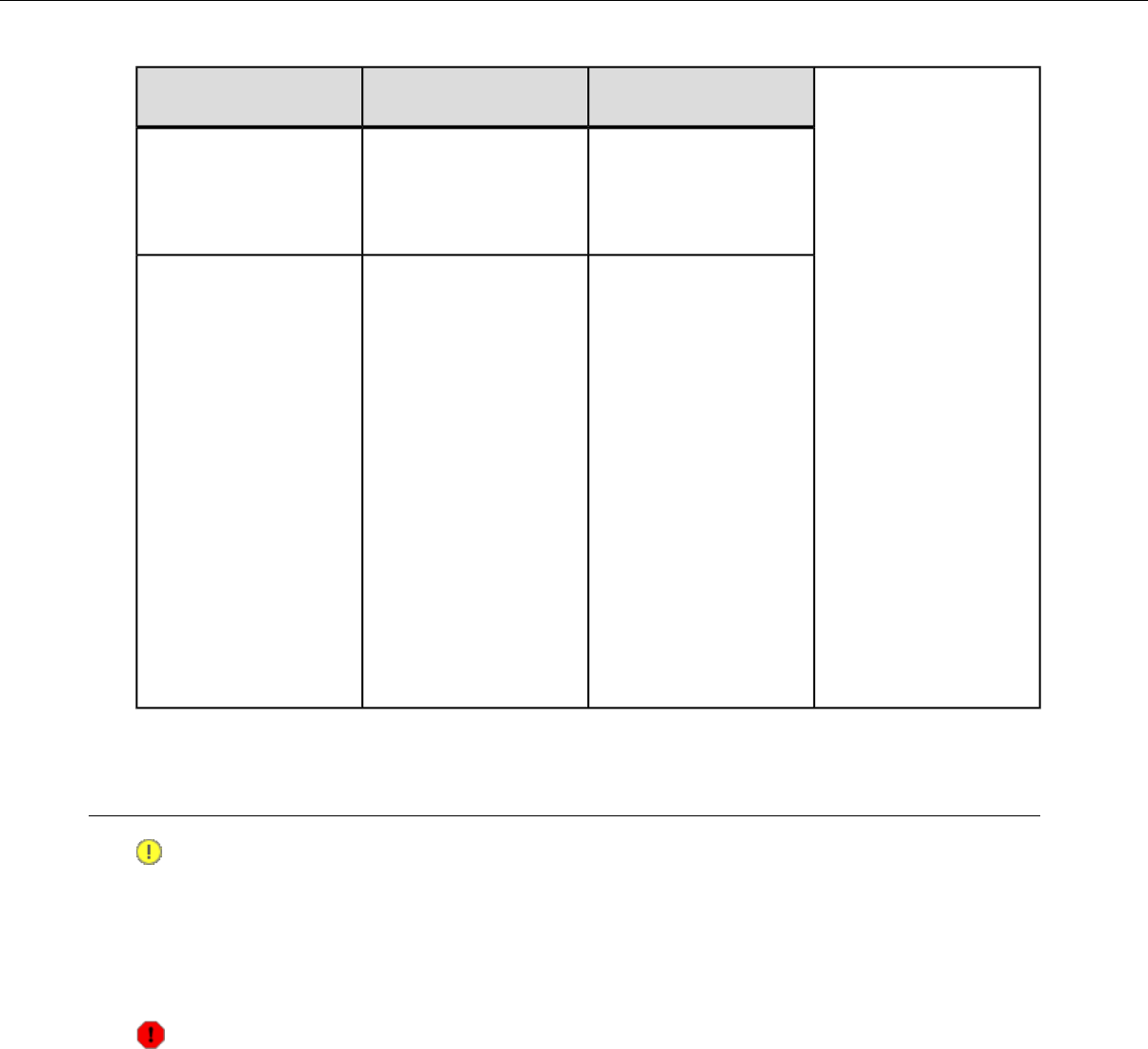
If the steps don't
work...
Try these steps...If this occurs...
Have the charger
replaced or repaired.
Check to see if the
contacts on the device
This is not able to be
corrected by a customer.
and charger are clean. If
not, follow cleaning
procedures and retry.
This is normal operation
and indicates that the
The power LED on a
5-bay charger is not
always green but flashes
amber. "DISTRIBUTABLE"
parameter has been set
to "1" for the device in
the master (gray color
tab) slot.
There is data
communication on the
serial port of the device
in the master slot. This
propagates the device
configuration to others
in the slot so that a new
device can be easily
accessed through
VoiceConsole without
serial configuration.
About Sending Equipment Back for Repairs
Important:
• Only equipment purchased directly from Vocollect can be returned to Vocollect for repairs.
•If you purchased Vocollect equipment — for example, a headset in the SR-Series — from a Vocollect
reseller, contact the reseller.
• If you are using Vocollect VoiceClient on a handheld device, contact the reseller or device
manufacturer if you have questions or issues concerning the device.
Attention: Remove ear pads, mounting discs, cables, and cord clips before shipping. These
consumable items slow down the repair process, and units will be shipped back without these
consumables installed.
Vocollect issues RMAs for all returns regardless of the reason for the return. This guarantees proper
tracking of equipment, ensures proper handling, and facilitates a fast return.
The Customer Service department generally issues RMAs to customers who are returning products for
repair. However, Vocollect may issue RMAs for other reasons, such as the following:
• The product belongs to Vocollect. Vocollect may have loaned the product to a customer or provided it
as a sample.
• Vocollect requested that the customer return the item, perhaps for testing.
• A Vocollect employee at the customer site has determined that the product should go back to Vocollect
for some other reason.
Confidential: For informational use by Vocollect Resellers and customers only
234 | Vocollect Hardware Documentation

• Exchange — for example, an incorrect item was shipped or the wrong size of belt was ordered.
Some Vocollect customers have service contracts with repair depots to perform repairs on Vocollect
products. Customers with these service contracts should contact their repair depot to return equipment.
Follow the RMA issuance procedures to eliminate unnecessary repair costs and to ensure timely product
receipt. If you have a question about the RMA process, please contact Customer Service.
Packaging Items for Return to Vocollect
Note: Properly packaged RMA items facilitate faster repair and return of Vocollect products.
Vocollect appreciates your assistance and adherence to these policies.
1. Pack items so that no items can come into direct contact with one another or with the sides, bottom,
or top of the shipping container.
2. Line the shipping container with at least one layer of padding, preferably anti-static bubble pack.
3. Pack each item individually in a bag or wrapping, preferably anti-static bubble bags or wrapping.
• If individual wrapping is not possible, place some packing material (such as anti-static bubble
pack) on the bottom of the shipping container, then pack items between layers of the material.
• Avoid using foam peanuts as the only packing material because they do not prevent items from
coming into contact with each other or the walls of the shipping container. Peanuts can, however,
fill empty space in the shipping container and on top of items that have been individually packed
in anti-static bubble bags.
Sending Equipment Back for Repairs: Return Material Authorization (RMA)
Procedures
1. Send an email to vocollect-rma@vocollect.com with the following information:
• Name of customer contact person
• Company name
• Company address
• Phone number
• Fax number
2. Also provide the following information about the items being returned:
• Quantity
• Description of product
• Serial number
• The version number of the software currently installed at your site
• Description of problem or reason for return
• Whether the product is covered by warranty, Extended Service Plan (ESP), or Depot Express
• A purchase order number if items are not covered by ESP or Depot Express
3. Include the RMA number on the shipping label, if shipping items to Vocollect.
4. Package the equipment according to the packaging instructions.
5. Address the shipping label to: Vocollect, Inc. 4250 Old William Penn Highway Monroeville, PA
15146-1622 RMA
Confidential: For informational use by Vocollect Resellers and customers only
Troubleshooting Equipment Problems | 235
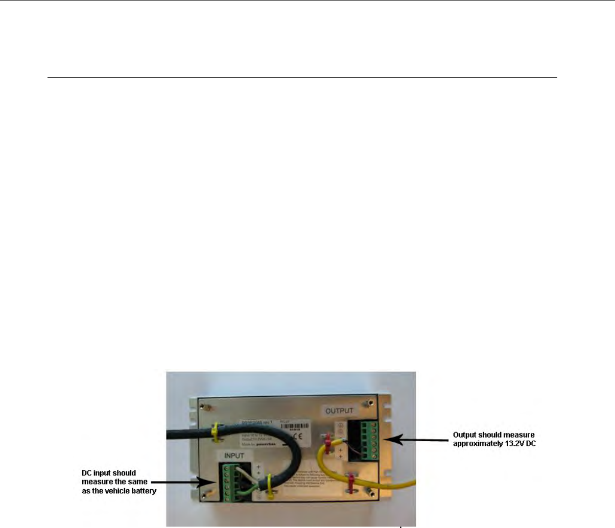
Troubleshooting VMT Configurations
The following procedures are for fault determination with Vehicle Mount Talkman (VMT) when powered
by the vehicle power system.
The following procedures can be done with minimal Vocollect technical support to determine the specific
malfunction of a non-working VMT:
• Be sure the vehicle battery is charged and working, turn-on the vehicle and assure it starts. If the
vehicle does not start then the vehicle should be serviced by qualified personnel.
• If VMT was installed after the vehicle key switch, ensure it powers on when the vehicle is turned on.
Vocollect recommends the VMT be installed before the vehicle key switch to ensure it is always getting
power when the vehicle has a battery.
• If another Talkman device is available, substitute it for the non-working Talkman. If this substitute
Talkman also does not work, it is likely the problem is with the VMT power system. However, if the
substitute works, then it is likely that the original device is in need of service.
• Exchange the VMT Battery Adapter from the non-working VMT with a known working Battery
Adapter. If the VMT works with the new Battery Adapter, then the original Battery Adapter is likely
in need of replacement.
The following steps will need qualified Vocollect technical support to determine the specific malfunction
of a non-working VMT:
Gain access to the power supply used by the VMT (this is likely mounted inside the vehicle). Remove
the four () screws that attach the lid of the power supply to expose the input and output wiring as
illustrated in the diagram below.
• Test the input terminals to determine if voltage is being supplied and matches that of the vehicle
power system.
• If the voltage supplied does not match that of the vehicle power system, professional attention is
needed to determine why the vehicle power system is not providing the correct voltage.
• If no voltage is being supplied, check the fuses on the input cable, replace if they are blown. If the
fuses immediately blow after replacement, determine if the input cable to the VMT power supply
has a short circuit. If there is no short then it is likely there is a problem with the VMT power
supply.
• If no voltage is being supplied and the fuses are not blown, check the integrity of the input cable
for a break. If there is a break, replace the cable. If not, there is likely a problem with the vehicle
power system that needs professional attention.
• If input voltage is being supplied to the power supply, check the output voltage.
Confidential: For informational use by Vocollect Resellers and customers only
236 | Vocollect Hardware Documentation
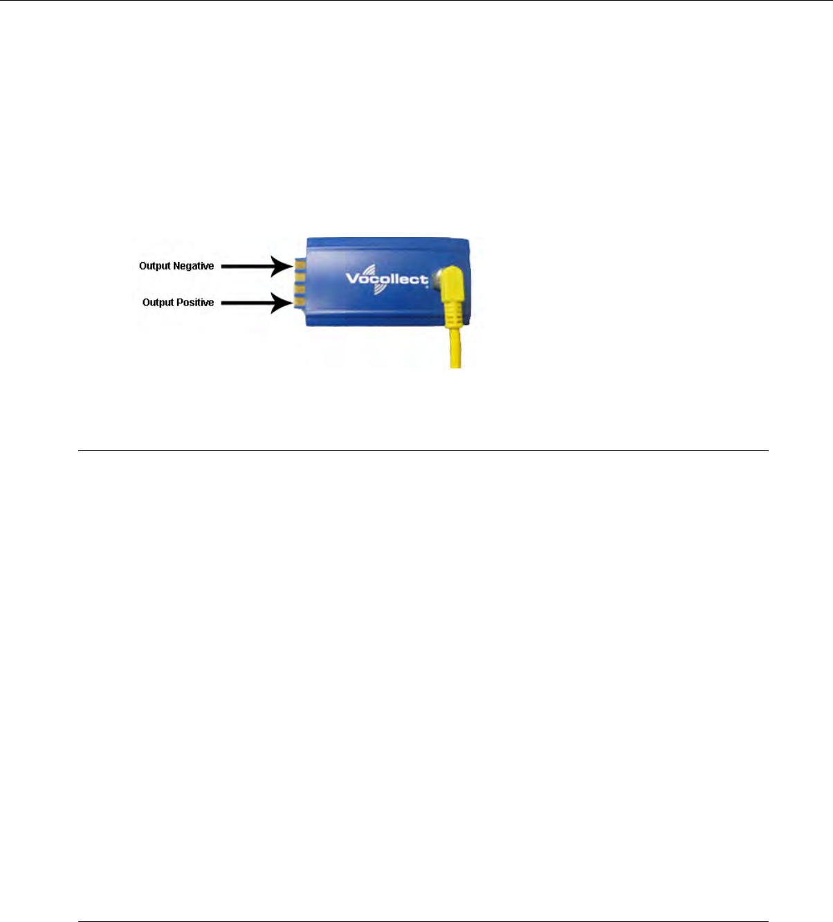
If there is input voltage but no output voltage or the output voltage does not match 13.2V DC then
the power supply is likely in need of replacement.
•
• If there is output voltage in the 13.2V DC range then the problem is likely in the cable to the
Battery Adapter or the Battery Adapter itself. Try a known, working Battery Adapter. If that does
not work then it is likely that the cable between the power supply and Battery Adapter is in need
of replacement.
•A Battery Adapter may be tested by checking the output of the adapter. Note that to rule out problems
with the power supply or cable to the Battery Adapter, a known, working Battery Adapter should be
tested first before testing a suspect Battery Adapter. The two outermost points of a working Battery
Adapter should read approximately 3.9-4.2V DC as illustrated in the figure below.
Troubleshooting Problems Indicated by LED
Vocollect Talkman devices, chargers and the SRX headset and its charger have LEDs that indicate the
state of the equipment. These LEDs may be on, off or blink. In some cases an LED will blink, alternating
between two colors.
If the LEDs indicate that there is a problem, follow the troubleshooting steps to solve the problem.
1. Check the battery contacts and the charger contacts for dirt or other obstructions that might prevent
the contacts from connecting properly.
2. Clean the contacts, if necessary.
a) Use an isopropyl alcohol (isopropanol) swab or soft cloth dampened with isopropyl alcohol to clean
metal connection points.
b) If dirt or residue cannot be removed with the alcohol swab or cloth, use a soft, non-abrasive rubber
eraser to clean metal connection points. You can also use a three-row toothbrush style, general
cleaning brush with natural hog hair bristles to gently brush away dirt on the contacts.
c) Wipe again with isopropyl alcohol.
3. Try various combinations of batteries and chargers to determine if the condition is specific to the
battery or to the charger.
• If the condition is specific to the battery, give the battery to your system administrator.
• If the condition is specific to the charger, disconnect the charger from its power source for about
five seconds, then reconnect it. Test the charger with a battery. If the same condition occurs, return
the charger for service.
About Error Messages
Error messages may be of one of two types:
Confidential: For informational use by Vocollect Resellers and customers only
Troubleshooting Equipment Problems | 237
Numbered Messages display in VoiceConsole as the numeric value of the error, followed by the text
message that displays in Debug. If you have seen a numbered error message in VoiceConsole, see the
Numbered Error Messages topic.
Spoken Messages are heard through a headset. If you have heard an error message through a headset,
see the Spoken Error Messages topic.
Note: Not all numbered error messages displayed in VoiceConsole have a corresponding spoken
message.
Numbered Error Messages
SolutionTextNumber
Event detect initialization failed.0x020a 1. Turn the device off and then turn it back on
again.
Event control failed to create
shared data module.
0x0203
2. Reboot the device.
3. Reload VoiceClient.
Event control failed to create
shared data module.
0x0203
Change the battery.Battery is getting low.0x0206
Battery is getting low. Change
battery now.
0x0207
Battery is very low. Powering off.
Must replace battery after power
off complete.
0x0208
—Noise sampling procedure failed.0x0602
—Noise sampling procedure timed
out.
0x0603
—Invalid operator file name.0x0605
Train returned bad status to
UpdTrain.
0x060c 1. Turn the device off and then turn it back on
again.
2. Reboot the device.
3. Reload VoiceClient.
—Unable to train words. Not enough
free flash memory.
0x060e
Speak failed to initialize properly.0x0802 1. Check the crashdump file. For more information,
see the VoiceConsole online help.Speech-out failed. Audio system
failure.
0x0804
2. Turn the device off and then turn it back on
again.
Dialog power-off failed.0x1201 3. Reboot the device.
4. Reload VoiceClient.
—Task not loaded. No task name
available.
0x1202
—OperLoad failed -- TmplSend busy.0x1203
Confidential: For informational use by Vocollect Resellers and customers only
238 | Vocollect Hardware Documentation

SolutionTextNumber
—Operator load failed.0x1204
—Corrupted operator data.0x1205
—Noise sample failed.0x1206
—There are no operators in this
team.
0x1207
—Unable to retrieve operator files.0x1208
—Internal error loading operator.0x1209
—Task load failed.0x120a
—Self test mode set, but no script
file found.
0x120b
—No task list file found. Task
unchanged.
0x120c
—Software error while changing
task. Task unchanged.
0x120d
—Failed to load look up table. Task
load failed.
0x120e
—Failed to load terminal emulation
configuration file. Task load failed.
0x1210
—Corrupt terminal emulation
configuration file. Task load failed.
0x1211
—Corrupt task file. Task load failed.0x1212
—Failed to load task Vocollect
configuration file. Task load failed.
0x1213
—Failed to write the output data
record network transport
0x1214
information registration file. Task
load failed.
Failed to write dialog terminal-off
files in the terminal charger after
task or operator load.
0x1215 1. Reload the operator.
2. Reload the task.
3. Reload VoiceClient.
—Retraining word failed. Please try
again.
0x1216
—Initializing operator failed. Please
reload operator.
0x1217
—Failed to load task phonetic file.
Task load failed.
0x1218
—Failed to load task audio file. Task
load failed.
0x1219
Communications error: Process
message service receive error.
0x1402 1. Turn the device off and then turn it back on
again.
Confidential: For informational use by Vocollect Resellers and customers only
Troubleshooting Equipment Problems | 239

SolutionTextNumber
Communications error: Process
message service send error.
0x1403 2. Reboot the device.
3. Reload VoiceClient.
Communications error: Process
message service GetIdFromName
error.
0x1406
Communications error: Unable to
close Vocollect configuration file.
0x140a
Communications error: Unable to
delete Vocollect configuration file.
0x140f
Communications error: Vocollect
network transport information
registration failed.
0x1410
Communications error:
Unrecognized process message
service message.
0x1411
Communications error: Unable to
spawn bar code process.
0x1414
Communications error: Unable to
spawn serial process.
0x1415
Communications error: Bad FTP
command.
0x1417
Communications error: Bad socket
command.
0x141b
Error: Unable to initialize bar code
port.
0x1420
Display Mode host name or IP
address bad.
0x1421
Display Mode service name or port
bad.
0x1422
Error: Unable to initialize
Debug/training COM port.
0x1423
Socket host name or IP address
bad.
0x1425 1. Turn the device off and then turn it back on
again.
Socket service name or port bad.0x1426 2. Reboot the device.
3. Reload VoiceClient.
4. Reload the task.
5. Verify the task's output data records (ODRs) and
lookup tables (LUTs) have correct and valid
socket host and service information. If you need
assistance, contact Vocollect.
Unable to send file via socket.
Unable to open.
0x1427 1. Turn the device off and then turn it back on
again.
2. Reboot the device.
Confidential: For informational use by Vocollect Resellers and customers only
240 | Vocollect Hardware Documentation

SolutionTextNumber
3. Reload VoiceClient.
—Invalid Terminal Manager service
name or port.
0x142a
—Telnet session manager failed to
start.
0x142c
—Telnet client process failed to start.0x142d
—Telnet VT220 emulation process
failed to start.
0x142e
Unable to open send data file, for
telnet send.
0x142f 1. Turn the device off and then turn it back on
again.
Error, Unable to Initialize Printer
Port.
0x1430 2. Reboot the device.
3. Reload VoiceClient.
Unable to print label, unable to
open file.
0x1431
Printer Error, Process Message
Service Send Error.
0x1432
Comm Error, Unable to spawn
printer process.
0x1433
File Manager initialization failed.0x1600
File Manager process message
service receive failed.
0x1601
—Warning, low flash memory.0x1602
—Warning, low flash memory. You
must upload your collected data
now.
0x1603
Process history data initialization
failed.
0x1a01 1. Turn the device off and then turn it back on
again.
Process history data process
message service receive failed.
0x1a02 2. Reboot the device.
3. Reload VoiceClient.
Process history data process
message service retry failed.
0x1a03
Process history data file descriptor
structure error.
0x1a04 1. Turn the device off and then turn it back on
again.
Process history data lookup table
structure error.
0x1a05 2. Reload the task.
3. Reboot the device.
4. Reload VoiceClient.
Process history data bins to
records write error.
0x1a06 1. Turn the device off and then turn it back on
again.
Process history data power-off
error.
0x1a09 2. Reboot the device.
3. Reload VoiceClient.
Confidential: For informational use by Vocollect Resellers and customers only
Troubleshooting Equipment Problems | 241

SolutionTextNumber
Process history data process
message service initialization data
file descriptor failed.
0x1a0b
Video terminal emulation
initialization failed.
0x1e01
Video terminal emulation process
message service receive failed.
0x1e02
—Flash failed to virtual allocate the
flash device.
0x2100
—Flash failed to initialize the device
for the file system.
0x2101
—Flash failed to virtual copy the
flash device.
0x2102
—Flash failed because of erase block
argument was invalid.
0x2104
—Flash library failed during erase.0x2105
—Flash failed because of invalid
flash write pointer argument.
0x2106
—Flash library failed during write.0x2107
—Flash failed because of invalid
flash read pointer argument.
0x2108
—Flash library failed during read.0x2109
—Flash library failed while deleting
a file.
0x210a
—Flash library failed while finding
a file.
0x210b
—Flash failed to open the specified
file in RAM.
0x210c
—Flash failed to read the specified
file from RAM.
0x210d
—Flash failed to write the specified
file to RAM.
0x210e
—Flash library failed while opening
a file.
0x210f
—Flash library failed while closing
a file.
0x2110
—Flash had invalid flash file image
generator linked list.
0x2111
—Flash is full. Please wait while
Talkman turns off.
0x2112
—Flash library failed. Out of space.0x2115
Confidential: For informational use by Vocollect Resellers and customers only
242 | Vocollect Hardware Documentation

SolutionTextNumber
—Flash library failed during reclaim.0x2116
Spoken Error Messages
SolutionError Message
Change the battery."Battery is very low. Powering off. Must
replace battery after power off complete."
Change the battery."Battery is getting low."
Change the battery."Battery is getting low. Change battery
now."
Wait until all templates are loaded, then load the operator."Cannot load operator while sending
templates."
"Cannot load task. Processing data." 1. Turn the device off and then turn it back on again.
2. Reload the task.
3. Reboot the device.
4. Reload VoiceClient.
"Corrupt task file. Task load failed." 1. Turn the device off and then turn it back on again.
2. Reload the task.
3. Reboot the device.
4. Reload VoiceClient.
"Corrupt device emulation config file.
Task load failed."
Reload the operator."Corrupted operator data."
"Failed to load lookup table. Task load
failed." 1. Go to an area of known good coverage.
2. Turn the device off and then turn it back on again.
3. Reload the task.
4. Reboot the device.
5. Reload VoiceClient.
"Failed to load task audio file. Task load
failed." 1. Go to an area of known good coverage.
2. Turn the device off and then turn it back on again.
3. Reload the task.
4. Reboot the device.
5. Reload VoiceClient.
"Failed to load task phonetic file. Task
load failed." 1. Go to an area of known good coverage.
2. Turn the device off and then turn it back on again.
3. Reload the task.
4. Reboot the device.
5. Reload VoiceClient.
Confidential: For informational use by Vocollect Resellers and customers only
Troubleshooting Equipment Problems | 243

SolutionError Message
"Failed to load task VCF file. Task load
failed." 1. Go to an area of known good coverage.
2. Turn the device off and then turn it back on again.
3. Reload the task.
4. Reboot the device.
5. Reload VoiceClient.
"Failed to load device emulation config
file. Task load failed." 1. Go to an area of known good coverage.
2. Turn the device off and then turn it back on again.
3. Reload the task.
4. Reboot the device.
5. Reload VoiceClient.
"Failed to write the ODR NTI
registration file. Task load failed." 1. Reload the task.
2. Turn the device off and then turn it back on again.
3. Reboot the device.
4. Reload VoiceClient.
"Firmware error while changing task.
Task not changed." 1. Reload the task.
2. Turn the device off and then turn it back on again.
3. Reboot the device.
4. Reload VoiceClient.
"Flash error." 1. Turn the device off and then turn it back on again.
2. Reboot the device.
3. Reload VoiceClient.
"Flash is full. Please wait while Talkman
turns off." 1. Go to an area of known good coverage.
2. Turn the device off and then turn it back on again.
3. Reboot the device.
4. Reload VoiceClient.
Change the battery."Headset battery is getting low."
Change the battery."Headset battery is getting low. Change
headset battery now."
"Initializing operator failed. Please
reload operator." 1. Reload the operator.
2. Turn the device off and then turn it back on again.
3. Reboot the device.
4. Reload VoiceClient.
"Internal error loading operator." 1. Turn the device off and then turn it back on again.
2. Reboot the device.
3. Reload VoiceClient.
Select the operator again or load a different operator."Invalid operator file name."
Confidential: For informational use by Vocollect Resellers and customers only
244 | Vocollect Hardware Documentation
SolutionError Message
"Invalid device Manager Host name or
address."
"Invalid device Manager Service name
or port."
"No task list file found. Task
unchanged." 1. Reload the task.
2. Turn the device off and then turn it back on again.
3. Reboot the device.
4. Reload VoiceClient.
"Noise sampling procedure failed." 1. Sample noise again.
2. Go to a quieter location and perform another noise sample.
3. Try using another headset and perform the noise sample.
Note: If this solves the problem, the first headset
might be damaged.
"Noise sampling procedure timed out." 1. Sample noise again.
2. Reboot the device.
"Operator load failed." 1. Go to an area of known good coverage.
2. Turn the device off and then turn it back on again.
3. Reboot the device.
4. Reload VoiceClient.
"Power-off error." 1. Power on the device.
2. Reboot the device.
Edit the task configuration file, taskname.vcf, and change the
line selftest=1 to selftest=0.
"Self test mode set, but no script file
found."
"Software error while changing task.
Task unchanged." 1. Go to an area of known good coverage.
2. Turn the device off and then turn it back on again.
3. Reload the task.
4. Reboot the device.
5. Reload VoiceClient.
"Task load failed." 1. Go to an area of known good coverage.
2. Turn the device off and then turn it back on again.
3. Reload the task.
4. Reboot the device.
5. Reload VoiceClient.
"Task not loaded. No task name
available." 1. Reload the task.
2. Turn the device off and then turn it back on again.
3. Reboot the device.
Confidential: For informational use by Vocollect Resellers and customers only
Troubleshooting Equipment Problems | 245

SolutionError Message
4. Reload VoiceClient.
"Telnet client process failed to start." 1. Turn the device off and then turn it back on again.
2. Reboot the device.
3. Reload VoiceClient.
"Telnet session manager failed to start." 1. Turn the device off and then turn it back on again.
2. Reboot the device.
3. Reload VoiceClient.
"Telnet VT220 emulation process failed
to start." 1. Turn the device off and then turn it back on again.
2. Reboot the device.
3. Reload VoiceClient.
"Unable to receive input data." 1. Turn the device off and then turn it back on again.
2. Reboot the device.
3. Reload VoiceClient.
"Unable to retrieve operator files." 1. Turn the device off and then turn it back on again.
2. Reboot the device.
3. Reload VoiceClient.
"Unable to send output data." 1. Turn the device off and then turn it back on again.
2. Reboot the device.
3. Reload VoiceClient.
"Unable to train words. Not enough free
flash memory." 1. Wait for the device to go to sleep.
2. Turn the device off and then turn it back on again.
3. Reboot the device.
4. Reload VoiceClient.
"Warning, low flash memory!" 1. Go to an area of known good coverage.
2. Turn the device off and then turn it back on again.
3. Reboot the device.
4. Reload VoiceClient.
5. Place the device in a charger as soon as possible.
"Warning, low flash memory! You must
upload your collected data now!" 1. Go to an area of known good coverage.
2. Turn the device off and then turn it back on again.
3. Reboot the device.
4. Reload VoiceClient.
5. Place the device in a charger as soon as possible.
Confidential: For informational use by Vocollect Resellers and customers only
246 | Vocollect Hardware Documentation

Chapter 14
Contacting Technical Support
This section describes what you will need before contacting technical support with an issue and how to
gather the needed files.
General Information Needed for Most Support Requests
Vocollect Talkman modelDevices Types
Non-Talkman device manufacturer/model
Vocollect headset model
Other headset
Bar code reader type
VoiceClient version displayed in VoiceConsoleVocollect Voice Software
VoiceCatalyst version displayed in VoiceConsole
VoiceConsole versionVocollect VoiceConsole
Have you begun to capture device logs?
Be prepared to submit these files to your technical support center.
Device Logs
Common Questions to Answer when Contacting Support
• Was a previous service request for the same problem / question closed as unresolved?
• How many users are affected?
• How often does the issue happen?
• What is the current workaround?
• When did the issue first occur?
• How is this impacting the business?
• Has anything about the environment changed?
Enabling Device Logging in VoiceConsole
1. Select VoiceConsole >Device Management >Devices.
2. Click the name of the device for which you want to enable logging.
The properties window for that device will appear.
3. Enable logging for the device. Depending on the version of VoiceConsole you are running:
Confidential: For informational use by Vocollect Resellers and customers only

Activate the Enable check box in the Logging section.
VoiceConsole 2.x
Click the Edit selected device link.
In the logging section of the Edit Device page, select Enabled from
the Logging Enabled drop-down list.
VoiceConsole 3.x and newer
4. After the issue has been captured in the log file, export the log file through the Device Properties
window.
5. Save the file and send it to Technical Support, along with any other relevant information.
Confidential: For informational use by Vocollect Resellers and customers only
248 | Vocollect Hardware Documentation

Appendix A
Compliance
Vocollect®Regulatory Compliance
Statement of Agency Compliance
Vocollect devices, and wireless headsets are designed to be compliant with the rules and regulations in
the locations into which they are sold and are labeled as required. Vocollect devices are type approved
and do not require the user to obtain license or authorization before using them. Changes or modifications
not expressly approved by Vocollect, Inc. could void the user's authority to operate the equipment.
Federal Communications Commission Compliance
FCC Class B Compliance Statement
Part 15 (b) of the Federal Communications Commission (FCC) Rules
This device complies with part 15 of the FCC Rules. Operation is subject to the following two conditions:
(1) This device may not cause harmful interference, and (2) this device must accept any interference
received, including interference that may cause undesired operation.
Note: This equipment has been tested and found to comply with the limits for a Class B digital device,
pursuant to Part 15 of the FCC Rules. These limits are designed to provide reasonable protection against
harmful interference in a residential installation. This equipment generates, uses and can radiate radio
frequency energy and, if not installed and used in accordance with the instructions, may cause harmful
interference to radio communications. However, there is no guarantee that interference will not occur
in a particular installation. If this equipment does cause harmful interference to radio or television
reception, which can be determined by turning the equipment off and on, the user is encouraged to try
to correct the interference by one or more of the following measures:
• Reorient or relocate the receiving antenna.
• Increase the separation between the equipment and receiver.
•Connect the equipment into an outlet on a circuit different from that to which the receiver is connected.
• Consult the dealer or an experienced radio/TV technician for help.
Radio
The Talkman®devices are nominally Class B digital devices, pursuant to Part 15 of the FCC Rules.
Caution: Exposure to Radio Frequency Radiation.
• The following devices each contain an internal low-power radio: Talkman®devices and SRX
Wireless Headset.
•The radiated output power of Vocollect®devices and headsets is far below the FCC radio frequency
exposure limits.
• Nevertheless, Vocollect®devices shall be used in such a manner that the potential for human
contact with the radio antenna during normal operation is minimized. The device should not be
used if the case is open or if the internal antenna is exposed. When not in use, the Vocollect®
devices should be powered off. In addition, the device should be worn in accordance with the
instructions for this device.
Confidential: For informational use by Vocollect Resellers and customers only

Vocollect products contain one of the following radio devices. See device label.
Maximum
SAR
Value (10
gram
average)
Maximum
SAR
Value (1
gram
average)
Canadian ID #FCC ID#Card Manufacturer
and P/N
Vocollect Device
No data
available
0.390W/kg2570A-TT60-50300MQOTT600-50300
Vocollect Wi-Fi
600-2400-032
T2x
Model: TT-600
No data
available
0.531W/kg2570A-TT601300MQOTT601-30000Summit SDC-CF10G
T2x
Model:TT-601_R
WF (RoHS
Compliant)
No data
available
0.471W/kgMQOTT700-10000MQOTT700-10000USI WM-BB-AG-01
T5
Model:TT-700-100
No data
available
0.689W/Kg2570A-TT700200MQOTT700-20000
Summit SDC-MCF10G
Murata LBMA46LBA3
T5
Model:TT-700-100_R
(RoHS Compliant)
0.016W/Kg0.038W/Kg2570A-TAP70001MQO-TAP700-01
Summit SDC-MCF10GT5
Murata
MURATA-LBMA46LCS3-
TEMP
Model:TAP700-01
No data
available
0.056W/Kg2570A-SRX10000MQOSRX-10000CSR BlueCore
3-Multimedia
BC358239A
SRX
Model: HD-800-1
0.186W/kg0.254W/kg2570A-HBT100001MQO-HBT1000-01CSR BlueCore
5-Multimedia Plug-n-Go
SRX2
Model: HBT1000-01
0.190W/Kg0.382W/Kg2570A-TT10011MQO-TT-100-1-1Summit SDC-MCF10G
T1
Model: TT-100-1-1
0.062
W/Kg
0.148
W/Kg
2570A-TT80011MQO-TT-800-1-1USI WM-BA-MR-01
A500
Model: TT-800-1-1
0.016
W/Kg
0.027
W/Kg
2570A-TAP80101MQO-TAP801-01Lesswire WiBear-SF
A500
Model: TAP801-01
Canadian Compliance
This Class B digital apparatus complies with Canadian ICES-003. Operation is subject to the following
two conditions:
1. This device may not cause harmful interference.
Confidential: For informational use by Vocollect Resellers and customers only
250 | Vocollect Hardware Documentation
2. This device must accept any interference received, including interference that may cause undesired
operation.
Cet appareil numérique de la classe B est conforme à la norme NMB-003 du Canada. Le présent appareil
est conforme aux CNR d'Industrie Canada applicables aux appareils radio exempts de licence.
L'exploitation est autorisée aux deux conditions suivantes:
1. L'appareil ne doit pas produire de brouillage.
2. l'utilisateur de l'appareil doit accepter tout brouillage radioélectrique subi, même si le brouillage est
susceptible d'en compromettre le fonctionnement.
CE Marking & European Compliance
Products intended for sale within the European Union are marked with the CE Mark, which indicates
compliance to applicable Directives and European Normes (EN) as follows. Amendments to these
Directives or ENs are included.
Device - T5 [MODEL: TT-700-100 and TT-700-100_R]
Important Notice: This device is a 2.4 to 2.48 GHz RF
device intended for office and light industrial use in all
EU and EFTA member states with restrictions in France
and Italy.
Device - T2x
Important Notice: This device is a 2.4 to 2.48 GHz RF
device intended for office and light industrial use in all
EU and EFTA member states with restrictions in France
and Italy.
Device - SRX
Important Notice: This device is a 2.4 to 2.48 GHz RF
device intended for office and light industrial use in all
EU and EFTA member states with restrictions in France
and Italy.
Italy Restrictions: If used outside of own premises, general authorization is required.
France Restrictions: Outdoor use is limited to 10mW e.i.r.p. within the band 2454-2483.5
Device - A500 [PART: TT-800; MODEL: TT-800-1-1]
Important Notice: This device is a wireless terminal that operates in the
2.4GHz and 5GHz ISM frequency bands and is intended for light industrial
use in all EU and EFTA member states. See restrictions below.
Italy Restrictions: If used outside of own premises, general authorization is required.
France Restrictions: Outdoor use is limited to 10mW e.i.r.p. within the band 2454-2483.5
This device must be used with Access Points that have employed and activated a radar detection feature
required for European Community operation in the 5 GHz bands. This device will operate under the
control of the Access Point in order to avoid operating on a channel occupied by any radar system in the
area. The presence of nearby radar operation may result in temporary interruption in communications
of this device. The Access Point's radar detection feature will automatically restart operation on a channel
free of radar. You may consult with the local technical support staff responsible for the wireless network
to ensure the Access Point device(s) are properly configured for European Community operation.
Confidential: For informational use by Vocollect Resellers and customers only
Compliance | 251

Device - A500 [PART: TT-801; MODEL: TT-800-1-1 and TAP801-01]
Device - T5 [PART: TT-700-100 and TT-700-100-M; MODEL: TAP700-01]
Device - T1 [PART: TT-100; MODEL: TT-100-1-1]
Device - SRX2 [PART: HD-1000-101; MODEL: HBT1000-01]
Regulatory Approvals for Bluetooth®Radio Devices
Vocollect devices that contain an integrated Bluetooth®module are designed to comply with the most
current applicable standards on safe levels of RF energy, developed by the Institute of Electrical and
Electronics Engineers (IEEE) and the American National Standards Institute Communications
Commission (FCC).
The Bluetooth word mark and logos are owned by the Bluetooth SIG, Inc. and any use of such marks by
Vocollect is under license. Other trademarks and trade names are those of their respective owners.
Made in the U.S.A.
Vocollect
Pittsburgh, PA
Declaration of Conformity: RoHS
Directive 2002/95/EC of the European Parliament and Council of 27 January 2003
Restriction of Hazardous Substances (RoHS)
Products Manufactured by Vocollect®
All Vocollect manufactured products shipped by Vocollect as of 1 July 2006 to destinations where the
DIRECTIVE 2002/95/EC OF THE EUROPEAN PARLIAMENT AND OF THE COUNCIL of 27 January
Confidential: For informational use by Vocollect Resellers and customers only
252 | Vocollect Hardware Documentation

2003 (RoHS) applies are compliant with this directive on the restriction of the use of certain hazardous
substances in electrical and electronic equipment.
The parts do not exceed the maximum concentrations by weight in homogenous materials for:
• 0.1% lead (Pb)
• 0.1% Hexavalent chromium (Cr6+)
• 0.1% polybrominated biphenyl (PBB)
• 0.1% polybrominated diphenyl ether (PBDE)
• 0.01% cadmium (Cd)
or qualify for an exemption to the above limits as defined in the Annex of the RoHS Directive.
Third Party products sold by Vocollect
Vocollect has obtained verification from all suppliers of all third party products that versions of those
products shipped by Vocollect as of 1 July 2006 to destinations where the DIRECTIVE 2002/95/EC OF
THE EUROPEAN PARLIAMENT AND OF THE COUNCIL of 27 January 2003 (RoHS) applies are
compliant with this directive on the restriction of the use of certain hazardous substances in electrical
and electronic equipment.
The parts do not exceed the maximum concentrations by weight in homogenous materials for:
• 0.1% lead (Pb)
• 0.1% Hexavalent chromium (Cr6+)
• 0.1% polybrominated biphenyl (PBB)
• 0.1% polybrominated diphenyl ether (PBDE)
• 0.01% cadmium (Cd)
or qualify for an exemption to the above limits as defined in the Annex of the RoHS Directive.
Vocollect®A500 Devices Declaration of Conformity
We the undersigned declare that the equipment has been designed to comply with the relevant sections
of the R&TTE Directive 1999/5/EC, Low Voltage Directive 2006/95/EEC & EMC Directive 89/336/EEC.
VocollectManufacturer's Name:
703 Rodi Rd., Pittsburgh, PA 15235, USAManufacturer's Address:
Certify and declare under our sole responsibility that the following equipment:
Vocollect®A500 Terminal products are used in voice directed data
acquisition. The terminals operate in the 2.4Ghz and 5GHZ ISM
frequency bands.
Product description / Intended
use:
Approved for use in all EU and EFTA member states.
Note: New members may be omitted or subject to change. For an up
to date official list please contact the EU government offices.
EU / EFTA Member states
intended for use:
US, CanadaOther Country approvals:
France, Italy - See User DocumentationMembers with Restrictive use:
VocollectManufacturer:
VocollectBrand:
Confidential: For informational use by Vocollect Resellers and customers only
Compliance | 253
A500 TerminalsType:
TT-800-1-1; TAP801-01Model(s):
Model: TT-800-1-1 and TAP801-01
Standards to which the
Conformity is declared:
EN 300 328 V1.7.1 EMC Radio Spectrum Matters
ETSI EN 301 489-1 V1.8.1 ERM EMC General & Immunity
ETSI EN 301 489 -17 V2.1.1 ERM EMC General & Immunity
EN 62311:2008 Human Exposure
EN 50371:2002 Human Exposure
EN 60950-1:2006/A11:2009/A1:2010 Product Safety
Model: TT-800-1-1
EN 300 440 – 2 EMC Radio Spectrum Matters
EN 301 893 5GHZ High Performance RLAN
Technical construction file is kept at the following address:
TT-800-1-1
TT-800-1-1
Contact:
Vocollect
703 Rodi Road
Pittsburgh, Pa 15235
U.S.A.
Phone: 412-829-8145
Fax: 412-829-0972
TAP-801-01
Rakesh Thapar
Vice President, Engineering
Document - 1002174 revision A
Copyright ©1998-2012 Vocollect, All Rights Reserved
Vocollect®T5 and T5m Devices and Talkman T5 VMT Mobile Computers
Declaration of Conformity
We the undersigned declare that the equipment has been designed to comply with the relevant sections
of the R&TTE Directive 1999/5/EC, Low Voltage Directive 2006/95/EEC & EMC Directive 89/336/EEC.
Vocollect, Inc.Manufacturer's Name:
703 Rodi Rd., Pittsburgh, PA 15235, USAManufacturer's Address:
Certify and declare under our sole responsibility that the following equipment:
Vocollect®T5 devices and battery chargers. Products are used in voice
directed wireless data acquisition devices operating in the 2.4Ghz
frequency band.
Product description / Intended
use:
Confidential: For informational use by Vocollect Resellers and customers only
254 | Vocollect Hardware Documentation
Approved for use in all EU and EFTA member states.
Note: New members may be omitted or subject to change. For an up
to date official list please contact the EU government offices.
EU / EFTA Member states
intended for use:
US, CanadaOther Country approvals:
France, Italy - See User DocumentationMembers with Restrictive use:
Vocollect, Inc. and Intelligent Technologies, Inc.Manufacturer:
VocollectBrand:
T5 Terminals and Battery ChargersType:
TT-700-100_R WF, TT-700-100_RG WF, TAP700-01, CM 700-1, CM
700-2, BT-710-1
Model(s):
For the Terminals:
EN 300 328 EMC Radio Spectrum Matters
EN 301 489 -1, -17 ERM EMC General & Immunity
EN 60950:2001 - Safety
Standards to which the
Conformity is declared:
For the battery chargers:
EN 60950:2001 - Safety
Emissions: EN 55022, EN 61000-3-2, EN 61000-3-3
Immunity: EN 55024, EN 61000-4-2, EN 61000-4-3, EN 61000-4- 4,
EN 61000-4-5, EN
61000-4-6, EN 61000-4-8, EN 61000-4-11
Technical construction file is kept at the following address:
Contact:
Vocollect, Inc
703 Rodi Road
Pittsburgh, Pa 15235
U.S.A.
Phone: 412-829-8145
Fax: 412-829-0972
Rakesh Thapar
Vice President, Engineering
Document - 1000474
Copyright ©1998-2012 Vocollect, Inc. All Rights Reserved
Vocollect®T2x Devices Declaration of Conformity
We the undersigned declare that the equipment has been designed to comply with the relevant sections
of the R&TTE Directive 1999/5/EC, Low Voltage Directive 2006/95/EEC & EMC Directive 89/336/EEC.
Vocollect, Inc.Manufacturer's Name:
703 Rodi Rd., Pittsburgh, PA 15235, USAManufacturer's Address:
Confidential: For informational use by Vocollect Resellers and customers only
Compliance | 255
Certify and declare under our sole responsibility that the following equipment:
Vocollect®T2 Series devices, device charger and battery chargers.
Products are used in voice directed data acquisition devices operating
in the 2.4Ghz ISM frequency band.
Product description / Intended
use:
Approved for use in all EU and EFTA member states.
Note: New members may be omitted or subject to change. For an up
to date official list please contact the EU government offices.
EU / EFTA Member states
intended for use:
US, CanadaOther Country approvals:
France, Italy - See User DocumentationMembers with Restrictive use:
Vocollect, Inc. & Global Components CorporationManufacturer:
VocollectBrand:
T2 device and Battery ChargerType:
TT-601_R WF, TT-601_RG WF, CM 601, CM 602, and CM 603Model(s):
For the devices:
Standards to which the
Conformity is declared:
EN 300 328 EMC Radio Spectrum Matters
EN 301 489 -1, -17 ERM EMC General & Immunity
EN 60950:2001 - Safety
For the battery chargers:
EN 60950:2001 - Safety
Emissions: EN 55022, EN 61000-3-2, EN 61000-3-3
Immunity: EN 55024, EN 61000-4-2, EN 61000-4-3, EN 61000-4- 4,
EN 61000-4-5, EN
61000-4-6, EN 61000-4-8, EN 61000-4-11
Technical construction file is kept at the following address:
Contact:
Vocollect, Inc.
703 Rodi Road
Pittsburgh, Pa 15235
U.S.A.
Phone: 412-829-8145
Fax: 412-829-0972
Rakesh Thapar
Vice President, Engineering
Document - 1000474
Copyright ©1998-2008 Vocollect, Inc. All Rights Reserved
Confidential: For informational use by Vocollect Resellers and customers only
256 | Vocollect Hardware Documentation
Vocollect®T1 Devices Declaration of Conformity
We the undersigned declare that the equipment has been designed to comply with the relevant sections
of the R&TTE Directive 1999/5/EC, Low Voltage Directive 2006/95/EEC & EMC Directive 89/336/EEC.
Vocollect, Inc.Manufacturer's Name:
703 Rodi Rd., Pittsburgh, PA 15235, USAManufacturer's Address:
Certify and declare under our sole responsibility that the following equipment:
Vocollect®T1 terminals, terminal and battery chargers. Products
are used in voice directed data acquisition. The terminals operate
in the 2.4Ghz ISM frequency band.
Product description / Intended
use:
Approved for use in all EU and EFTA member states.
Note: New members may be omitted or subject to change. For an up
to date official list please contact the EU government offices.
EU / EFTA Member states
intended for use:
US, CanadaOther Country approvals:
France, Italy - See User DocumentationMembers with Restrictive use:
Vocollect, Inc.Manufacturer:
VocollectBrand:
T1 Terminals and Battery ChargerType:
TT-100-1-1, CM-100-1, CM-103-1Model(s):
For the Terminals:
Standards to which the
Conformity is declared:
EN 300 328 EMC Radio Spectrum Matters
EN 301 489 -1, -17 ERM EMC General & Immunity
EN 60950-1:2006 - Safety
For the battery chargers:
EN 60950-1:2006 - Safety
Emissions: EN 55022, EN61000-3-2, EN 61000-3-3
Immunity: EN 55024, EN 61000-4-2, EN 61000-4-3,
EN 61000-4-4, EN 61000-4-5, EN 61000-4-6,
EN 61000-4-8, EN 61000-4-11
Technical construction file is kept at the following address:
Contact:
Vocollect, Inc
703 Rodi Road
Pittsburgh, Pa 15235 U.S.A.
Phone: 412-829-8145
Fax: 412-829-0972
Rakesh Thapar
Vice President, Engineering
Confidential: For informational use by Vocollect Resellers and customers only
Compliance | 257

Document-1002028 revision A
Copyright ©1998-2008 Vocollect, Inc. All Rights Reserved
Vocollect®SRX Wireless Headset Declaration of Conformity
We the undersigned declare that the equipment has been designed to comply with the relevant sections
of the R&TTE Directive 1999/5/EC, Low Voltage Directive 2006/95/EEC & EMC Directive 89/336/EEC.
Vocollect, Inc.Manufacturer's Name:
703 Rodi Rd., Pittsburgh, PA 15235, USAManufacturer's Address:
Certify and declare under our sole responsibility that the following equipment:
Vocollect®SRX Headset and battery chargers. Products are used
in voice directed wireless Bluetooth applications operating in
the 2.4Ghz frequency band.
Product description / Intended use:
Approved for use in all EU and EFTA member states.
Note: New members may be omitted or subject to change. For
an up to date official list please contact the EU government
offices.
EU / EFTA Member states intended
for use:
US, CanadaOther Country approvals:
Members with Restrictive use:
Vocollect, Inc. and Intelligent Technologies, Inc.Manufacturer:
VocollectBrand:
SRX Headset and Battery ChargersType:
HD-800-1, CM 800-1, CM 801-1Model(s):
Is tested and conforms with the essential requirements for the protection of health and safety of the user
and any person and Electromagnetic Compatibility, as included in the following standards.
For the SRX Headset:
Standards to which the
Conformity is declared:
EN 300 328 – Electromagnetic Compatibility and Radio Spectrum Matters
EN 301 489 -1, -17 ERM EMC General & Immunity
EN 60950:2001 - Safety
For the battery chargers:
EN 60950:2001 - Safety
Emissions: EN 55022, EN61000-3-2, EN 61000-3-3
Immunity: EN 55024, EN 61000-4-2, EN 61000-4-3, EN 61000-4-4, EN
61000-4-5, EN
61000-4-6, EN 61000-4-8, EN 61000-4-11
Technical construction file is kept at the following address:
Confidential: For informational use by Vocollect Resellers and customers only
258 | Vocollect Hardware Documentation
Contact:
Vocollect, Inc
703 Rodi Road
Pittsburgh, Pa 15235
U.S.A.
Phone: 412-829-8145
Fax: 412-829-0972
Rakesh Thapar
Vice President, Engineering
Document-1000280 revision A
Copyright ©1998-2008 Vocollect, Inc. All Rights Reserved
Vocollect®SRX2 Wireless Headset Declaration of Conformity
We the undersigned declare that the equipment named has been designed to comply with the relevant
sections of the R&TTE Directive 1999/5/EC, Low Voltage Directive 2006/95/EEC & EMC Directive
89/336/EEC.
VocollectManufacturer's Name:
703 Rodi Rd., Pittsburgh, PA 15235, USAManufacturer's Address:
Certify and declare under our sole responsibility that the following equipment is tested and conforms
with the essential requirements for the protection of health and safety of the user and any person and
Electromagnetic Compatibility, as included in the standards listed below.
Vocollect®SRX2 products are used in voice directed wireless Bluetooth
applications operating in the 2.4Ghz frequency band.
Product description / Intended
use:
Approved for use in all EU and EFTA member states.
Note: Members may be omitted or subject to change. For an up to date
official list please contact the EU government offices.
EU / EFTA Member states
intended for use:
US, CanadaOther Country approvals:
Vocollect Inc., & Intelligent Technologies, Inc.Manufacturer:
VocollectBrand:
SRX2 Headset, SRX2 Battery, and SRX2 Battery ChargerType:
HBT1000-01, HBA1000-01, and HCG1000-01Model(s):
SRX2 Headset (HBT1000-01):
EN 60950-1:2006/A11:2009/A1:2010 Product Safety
EN 300 328 V1.7.1 – EMC Radio Spectrum Matters
Standards to which the
Conformity is declared:
EN 301 489-1, V1.9.2 ERM EMC General & Immunity
EN 301 489-17, V2.1.1 ERM EMC General & Immunity
SRX2 Battery (HBA1000-01):
IEC/EN 62133:2002 (1st Edition)
Confidential: For informational use by Vocollect Resellers and customers only
Compliance | 259
SRX2 Battery Charger (HCG1000-01):
EN 60950-1:2006/A11:2009/A1:2010 Product Safety
Emissions: EN 55022, EN61000-3-2, EN 61000-3-3
Immunity: EN 55024, EN 61000-4-2, EN 61000-4-3, EN 61000-4-4, EN
61000-4-5, EN
61000-4-6, EN 61000-4-8, EN 61000-4-11
Technical construction file is kept at the following address:
Contact:
Vocollect, Inc
703 Rodi Road
Pittsburgh, Pa 15235 U.S.A.
Phone: 412-829-8145
Fax: 412-829-0972
Rakesh Thapar
Vice President, Engineering
Document-1003157 Revision A
Copyright ©2012 Vocollect. All Rights Reserved.
Confidential: For informational use by Vocollect Resellers and customers only
260 | Vocollect Hardware Documentation

Appendix B
Template Training Options
All new operators must train their voice templates in order to perform a task with the Vocollect Voice
system. Supervisors have four options for operators to train templates when using a device.
Note: Always speak in your normal tone of voice when training templates.
Training with the Talkman Device Only
Once a new operator is recognized by a Talkman device, the Vocollect Voice system instructs him/her to
train all the words he/she will use in the task.
Note: This process can be improved when used in conjunction with the section “Training Using a
Printed List of Words” as found below.
Note: Your supervisor must set up the system to use the voice-only option for creating templates
with a handheld device.
1. Turn your device on by pressing the Play/Pause button.
The LED indicator turns red for a few moments then turns green. The device says, "Please keep quiet
for a few seconds." After a pause, the device says, "Please say zero."
2. Say "Zero."
The device says "One."
3. Say "One."
The device says, "Two."
4. Say "Two."
The device says, "Please say the following words..."
5. As the device says each word, say it back to the device. The device will prompt you with the same
word at least four times; repeat the word each time it asks. If it prompts you for phrases, say the
phrase naturally, without pauses between the words.
When the device has asked for all words in the task the necessary number of times, the device will
say, "Creating voice templates. Please wait." It will then beep periodically until all of the remaining
voice templates have been created. When the remaining voice templates have been created, the device
says, "Finished creating voice templates." The device then goes to sleep. You can begin the task by
pressing the Play/Pause button.
Training Using and Visual Training Device
Note: This is not supported on the Talkman T1.
1. Be sure the training device is configured.
2. Connect the training device to your Talkman T-Series device.
3. Turn your Talkman device on by pressing the Play/Pause button.
Confidential: For informational use by Vocollect Resellers and customers only

The LED indicator turns red for a few moments then turns green. The training device displays, "Please
keep quiet for a few seconds."
Note:
• If your device does not say this, press the Operator button to manually perform a background
noise sample.
• If you cannot see words displayed on the training device screen, there may be a problem with
the contrast on the device. Refer to the manufacturer's documentation.
• The Talkman device says and the training device displays, "Please say zero."
4. Say "Zero."
The Talkman device says and the training device displays, "One."
5. Say "One."
The Talkman device says and the training device displays, "Two."
6. Say "Two."
The Talkman device says, "Please say the following words as they appear on the screen."
The Talkman device stops speaking and words to train are only displayed on the screen. Speak the words
as they appear on the device display. Words appear in random order and are repeated at least four times
to get an accurate recording of how you speak the words. If it prompts you for phrases, say the phrase
naturally, without exaggerated pauses between the words.
When the device has asked for all words in the task the necessary number of times, the device will say,
"Creating voice templates. Please wait." It will then beep periodically until all of the remaining voice
templates have been created.
During the beeping, the device periodically repeats the "... Please wait" phrase to alert the user that it
is still busy. When the remaining voice templates have been created, the device says, "Finished creating
voice templates." The device then goes to sleep. You can begin the task by pressing the Play/Pause button.
You can expect the device to beep for approximately two minutes after all of the vocabulary words have
been spoken. If the operator presses any of the device's buttons during this time period, the device says,
"Creating voice templates. Please wait."
Disconnect the training device and begin your task by pressing the Play/Pause button.
Training through VoiceConsole's Display
Note: Supported when using VoiceConsole 3.0 or newer and VoiceClient 3.5 and newer.
If you are using VoiceConsole 3.0 or newer and VoiceClient 3.5 or newer, you can view the words the
device asks you to train on a computer screen, through the user interface, or pocket PC device screen as
you go through the training process. See Viewing Dialog Between and Device and an Operator in the
VoiceConsole online help for more information.
Training Using a Printed List of Words
Note: Supported when using VoiceConsole 3.1 or newer.
Note: This is the recommended training method for the Talkman T1.
Confidential: For informational use by Vocollect Resellers and customers only
262 | Vocollect Hardware Documentation
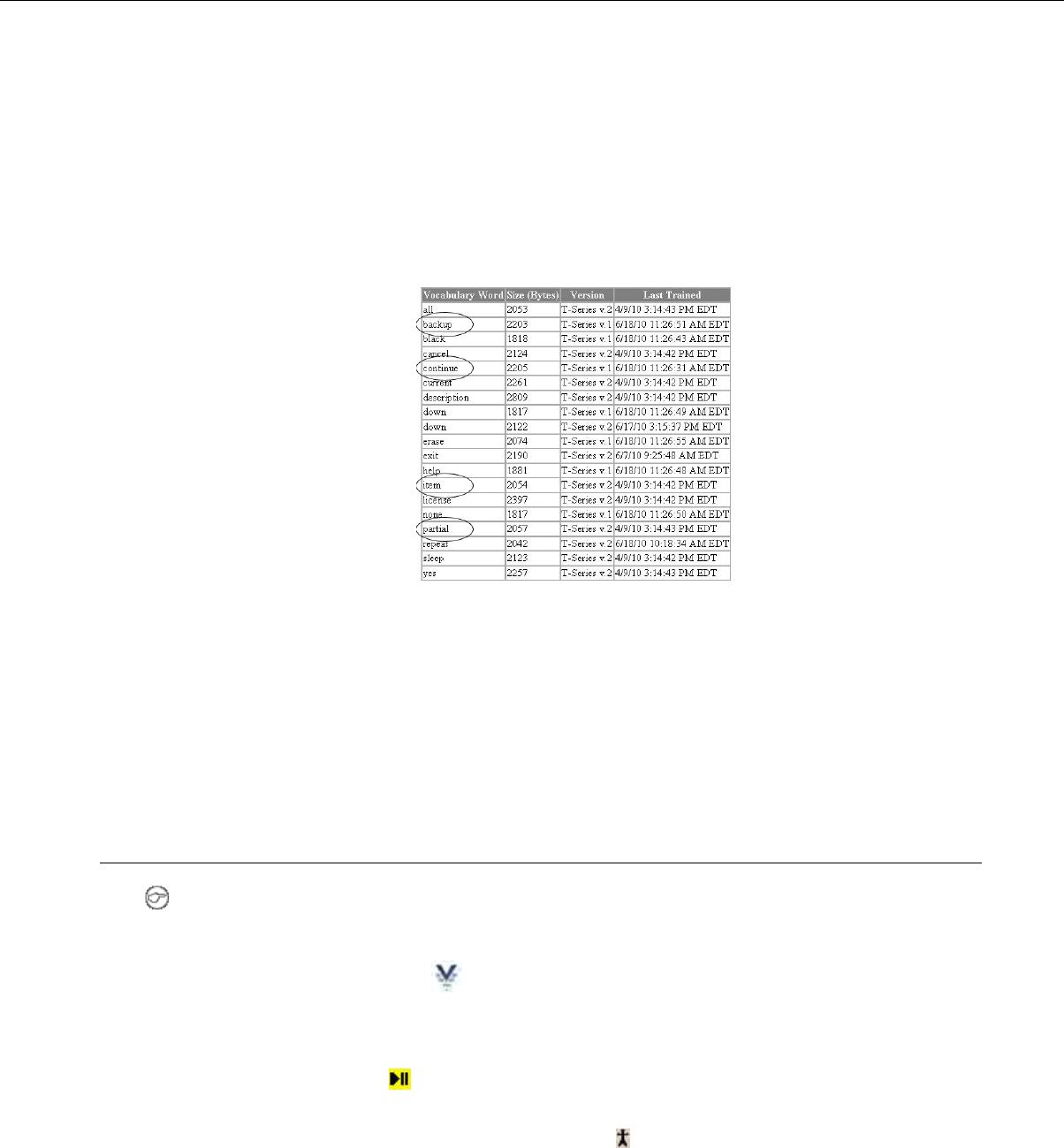
If you suspect operators may have a difficult time recognizing the words the device is speaking during
training, you can create a print out of the words used in the task that the device will ask the operators
to train.
1. If a current operator has previously performed the task the new operator is going to use, go to
VoiceConsole and perform the steps for viewing an operator’s voice templates using the current
operator. See Managing Operator Numbers in the VoiceConsole online help for more information.
2. On the Manage Operator Templates:<operator name> page in VoiceConsole, print the list of trained
words. See Viewing Printable Versions of List Data in the VoiceConsole online help.
3. If necessary, on the printed list, circle commonly misheard or confusing words.
Figure 170: Printed List with Commonly Misheard or Confusing Words Circled
4. Vocollect recommends the new operator review the list prior to training so he/she is familiar with the
words that will be used
If templates have not been trained for the task the new operator is going to use, have the supervisor or
current operator train templates for that task and perform the steps above. To proceed with the actual
training, follow the detailed list of instructions in the “Training with the Talkman Only” section above.
Training Using the Handheld Device Screen
Note: This is not supported on Talkman devices.
1. On the device screen, tap Start.
2.
Tap the Vocollect Voice symbol.
The Vocollect Voice screen displays. The status indicator turns red for a few moments then turns
green. The device says, "Current operator is <name>. <Number> words not trained. Good night."
Make sure the device says your name. If it does not, check with your supervisor or trainer.
3. Tap the play/pause button on the device screen. The device says, "Please keep quiet for a few
seconds."
If the device does not say this, tap the operator button to manually perform a background noise
sample.
The device says, "Please say zero."
4. Say "Zero."
The device says, "One."
Confidential: For informational use by Vocollect Resellers and customers only
Template Training Options | 263

5. Say "One."
The device says, "Two."
6. Say "Two."
The device says, "Please say the following words as they appear on the screen."
The Voice Training text box displays.
Figure 171: Voice Training text box
If you cannot see the words displayed on the training device screen, there may be a problem with the
contrast on the device. Refer to the manufacturer's documentation.
As each word appears on the device display, say it to the device. The device will display the same word
at least four times; repeat the word each time it appears. If you see phrases, say the phrase naturally,
without exaggerated pauses between the words.
When the device has asked for all words in the task the necessary number of times, the device will say,
"Creating voice templates. Please wait." It will then beep periodically until all of the remaining voice
templates have been created.
During the beeping, the device periodically repeats the "... Please wait" phrase to alert the user that it
is still busy. When the remaining voice templates have been created, the device says, "Finished creating
voice templates." The device then goes to sleep. You can begin the task by pressing the Play/Pause button.
You can expect the device to beep for approximately two minutes after all of the vocabulary words have
been spoken. If the operator presses any of the device's buttons during this time period, the device says,
"Creating voice templates. Please wait."
Confidential: For informational use by Vocollect Resellers and customers only
264 | Vocollect Hardware Documentation

Index
A
A500 charger
152
LED indicators 152
A500 device
35–36, 38–44, 52, 54, 56–57, 60–63, 65–68, 76,
78–79, 84–85, 89, 147–148, 180–181, 186
accessories 52
battery 36, 60
battery specifications 36, 61
charging 36, 60
combination charger 147
combination charger, specifications 148
device cover 56, 78, 89
device cover specifications 57, 79
device cover, putting on 57, 79
display 52
inserting battery 38, 62, 84
LED indicators 40
pairing bar code scanner 41, 65
pairing display 52
pairing Honeywell LXE 8652 42–43, 66–67, 180–181
pairing Honeywell MS9535 41, 65–66
pairing printer 41–42, 66
pairing Socket cordless ring scanner 44, 68, 186
Pidion BM-170 52
removing battery 39, 63, 85
removing from charger 38, 62, 84
shoulder harness 54, 76
specifications 35
A500 VMT
44–45, 47–48, 69, 71–72
accessories 45, 69
connecting cables 48, 72
installing in vehicle 44, 69
positioning in forklift 47, 71
accessories
26, 44, 51–52, 55, 69, 76–77, 87–88, 95–96, 202,
204
belts, belt clips 55, 77, 88
cables 202
cables, part numbers 204
Pidion BM-170 display 52
T1 device holster 96
Talkman devices 51, 76, 87, 95, 202
Talkman, part numbers 26
vehicle mount 44, 69
adapter cables
202–203
connecting headset to handheld device 203
connecting listening device 203
adaptive speech recognition 207
adjustable shoulder harness
54, 76
specifications 54, 76
agency compliance 249
B
bar code reader problems
229
won't scan 229
bar code readers
173–174, 176–177, 182–183, 185–186, 188–190,
192, 194, 196–197, 202, 205
accepting input 202
accessories 205
configuring for voice 202
connecting to a device 196
device adapter 194
disconnecting from a device 197
Honeywell 9535 Bluetooth 183
Honeywell IS4220 182
Honeywell IS4225 182
Honeywell LXE 8652 176
Honeywell LXE Ring Scanner 8651 176
Intermec SF51 174, 176
part numbers 205
serial interface cable 194
Socket Cordless Ring Scanner 185
Socket CRS, configuring 186
Symbol LS3408-ER20005 190
Symbol LS3408-FZ20005 190
Symbol LS4208 188
Symbol RS 1 Ring Scanner 192
bar code readers, pairing
41–44, 65–68, 174–175, 180–181, 186, 198–201
Honeywell LXE device 198
Intermec SF51 ring scanner 175
Intermec SF51 scanner 174–175
with A500/T-Series devices 41, 65
with Intermec device manually 201
with Intermec device, quick connect 201
with Intermec device, search 200
with Psion device 198
with Psion WAP G2 199
batteries
16, 36, 38–39, 60–64, 82, 84–86, 92–94, 115–116,
124–127
charging SRX headset 115
charging SRX2 headset 125
charging T1 93
charging, A500 device 36, 60
charging, T1 device 92
charging, T2x device 82
charging, T5 device 36, 60
handling 16
inserting into SRX headset 116
inserting into SRX2 headset 126
inserting into T1 device 93
inserting into Talkman devices 38, 62, 84
Confidential: For informational use by Vocollect Resellers and customers only
Index | 265

batteries (continued)
removing from SRX headset 116
removing from SRX2 headset 126
removing from T1device 94
removing from Talkman devices 39, 63, 85
specifications, A500 device 36, 61
specifications, T5 device 36, 61
SRX headset 115
SRX2 headset 124–125
T1 device 92
T2x device 82
warm-up time 39, 64, 86, 94, 116, 127
battery safety 16, 115, 124
beeping 230
belt clips 55, 77, 88
belts
55–56, 77–78, 88–89, 96
sizes 56, 78, 89, 96
specifications 56, 78, 89, 96
blinking 40, 64, 86, 94, 151–152, 158, 170
blue 40, 64, 86
Bluetooth
41–42, 44, 52, 65–66, 68, 87, 132–137, 139, 186,
195, 198–201
pairing 87
pairing A500/T5-Series devices 41, 65
pairing by VoiceConsole 137
pairing Honeywell MS9535 with A500 41, 65–66
pairing Honeywell MS9535 with T5 41, 65–66
pairing Intermec PB50 printer with A500 42, 66
pairing Intermec PB50 printer withT5-Series 42, 66
pairing scanner with Intermec device 200–201
pairing Socket ring scanner with T5-Series device 44,
68, 186
pairing SRX/SRX2 with Talkman device 139
pairing SRX2 135–136
pairing SRX2 headset 133, 135
pairing SRX2 headset with handheld device 134, 136
pairing wireless headsets 132
pairing Zebra QL printer with A500 41, 66
pairing Zebra QL printer with T5-Series 41, 66
button, not responding 230
C
cables
182, 202, 204
part numbers 204
RJ11 182
charger stand
153
assembling, T2x battery charger 153
chargers
32, 38, 62, 84, 93, 147–154, 159–160, 162–168
assembling stand, T2x battery charger 153
connecting power supply 150
part numbers 32
removing A500 device 38, 62, 84
removing T1 device 93
removing T2-Series device 38, 62, 84
removing T5-Series device 38, 62, 84
single charger cable 163
chargers (continued)
SRX headset battery 164
SRX wall mount 165–166, 168
SRX2 headset battery 167
SRX2 wall mount 168
T1 10-Bay
150, 159–160
specifications 159
T1 single 163
T1 single charger cable 163
T1 single charger cable, specifications 163
T1 wall mount 160
T2 battery 152
T2 wall mount 154
T2x battery 152
T2x battery charger, specifications 153
T2x wall mount 154
T5/A500 10-bay Combination Charger 147
T5/A500 combination, attaching power supply 162
T5/A500 combination, installing wall mount 151
T5/A500 combination, power supply specifications 149
T5/A500 combination, specifications 148
T5/A500 combination, wall mount 150
wall mount 154, 160, 165–166, 168
CK3 device
200–201
pair scanner with search 200
pairing scanner manually 201
pairing scanner with quick connect 201
CK70 device
200–201
pair scanner with search 200
pairing scanner manually 201
pairing scanner with quick connect 201
CK71 device
200–201
pair scanner with search 200
pairing scanner manually 201
pairing scanner with quick connect 201
cleaning procedures 17
CN70 device
200–201
pair scanner with search 200
pairing scanner manually 201
pairing scanner with quick connect 201
CN70e device
200–201
pair scanner with search 200
pairing scanner manually 201
pairing scanner with quick connect 201
cold battery 39, 64, 86, 94, 116, 127
combination charger
147–151, 159–160, 162
attaching power supply 162
easy configuration 148
easy configuration, additional devices 149
easy configuration, setup 148
power supply specifications 149
specifications 148
wall mount 150
wall mount, installing 151
commands 26
Confidential: For informational use by Vocollect Resellers and customers only
266 | Vocollect Hardware Documentation

compatibility
124
SRX2 with devices 124
SRX2 with Vocollect Voice 124
compliance 249
configuration parameters
141
SRX/SRX2 headsets 141
conformity 252–255, 257–259
connector pins 193
copyright 3
covers, See device covers
D
danger 16
declaration of conformity
252–255, 257–259
devices 253–255, 257
SRX Wireless Headset 258
SRX2 Wireless Headset 259
device covers
56–57, 78–79, 89–90
A500 device 56, 78, 89
putting on A500/T5-Series device 57, 79
specifications 57, 79
T2 device 56, 78, 89–90
T2x device 56, 78, 89–90
T5 device 56, 78, 89
device problems
230–231
beeping 230
keeps shutting off 231
won't load a voice application 230
won't load an operator template 230
won't respond to button presses 230
won't turn on 230
devices
17, 35, 59, 81, 91
cleaning 17
Talkman A500 35
Talkman T1 91
Talkman T2 Series 81
Talkman T5 Series 59
display 52
dual-cup headset 109
E
earpad
129
replacing, SRX2 129
easy configuration
148–149
additional devices 149
setup 148
electronics module
123–124
attaching to SRX2 headset 123
removing from SRX2 headset 124
equipment
17
equipment (continued)
cleaning 17
equipment problems 229
error messages
237–238, 243
numbered 238
spoken 243
F
faster 25
FCC compliance 249
female 25
forklift
44, 47–48, 69, 71–72
connecting cables 48, 72
installing A500 or T5 into 44, 69
installing mounting brackets for device 47, 71
positioning device 47, 71
G
gender, changing 25
green 40, 64, 86, 94, 151–152, 158, 170
H
handheld devices
134–137, 207–212, 217, 219
changing voices, about 217
changing voices, enabling 217
charging 219
installing Vocollect Voice 207–211
pairing SRX headset with 134
pairing SRX2 headset with 136
pairing status icons 135, 137
setting default voice 212
hard-hat headset 108
hardware documentation, about 3
headset
109, 203
adapter cables 203
connecting to handheld device 203
SR-40 Dual-Cup 109
headset problems
229
can't hear anything 229
won't stay on 229
headset styles 27
headset supplies, part numbers 29, 31
headsets
21, 27, 99–101, 103–112, 114, 116, 121, 126, 143–
145, 196–197, 258–259
SL-14 headset, wearing 101
about 21
adjusting 110, 143
adjustment strap, SR-15 104–105
care and use 109, 143
choosing 27
cleaning 112, 145
cleaning windscreen 111, 144
Confidential: For informational use by Vocollect Resellers and customers only
Index | 267

headsets (continued)
connecting to a device 196
declaration of conformity 258–259
disconnecting from a device 197
headset features 27
inserting battery, SRX 116
inserting battery, SRX2 126
removing 111, 144
removing battery, SRX 116
removing battery, SRX2 126
SL-14 behind-the-head 99
SL-14 headset, using properly 101
SL-14 light-industrial behind-the-head 100
SL-4 behind-the-head 99
SL-4 headset, using properly 101
SL-4 light-industrial behind-the-head 101
SR-10 behind-the-head 103
SR-15 behind-the-head 103
SR-15 specifications 103
SR-15, wearing 104
SR-20 Lightweight 105
SR-20 Series 106
SR-20-Series Lightweight 105
SR-21 Lightweight 106
SR-30 High Noise specifications 107
SR-30 High-Noise 107
SR-31 High-Noise 107
SR-35 Hard-Hat 108
SR-35 Hard-Hat, specifications 108
SR-40 Dual-Cup 109
SRX Wireless 114
SRX2 Wireless 121
wearing 110, 143
headsets, wired
99
about 99
headsets, wireless
113
about 113
high-noise headset 107
higher 24
holster
96
specifications 96
Honeywell IS4220 Bar Code Reader
182
specifications 182
Honeywell IS4225 Bar Code Reader 182
Honeywell LXE 8652 Bluetooth Ring Scanner 176–177
Honeywell LXE 8652 scanner
42–43, 66–67, 180–181
pairing with T5-Series device 42–43, 66–67, 180–181
Honeywell LXE device
198
pair printer 198
pair scanner 198
Honeywell LXE Ring Scanner 8651 176
Honeywell MS9535 bar code reader
41, 65–66
pairing with A500/T5-Series device 41, 65–66
Honeywell MS9535 Bar Code Reader 183–184
I
inline adapter cables
202–203
connecting headset to handheld device 203
connecting listening device 203
Intermec device
200–201
pair scanner with search 200
pairing scanner manually 201
pairing scanner with quick connect 201
Intermec PB50 printers
42, 66
pairing with A500/T5-Series device 42, 66
Intermec SF51 Cordless Scanner 174
L
LED
170
T5 charger 170
T5m charger 170
LED indicators
40, 64, 86, 94, 119, 130, 151–152, 158, 170, 237
A500 40
A500 charger 152
SRX headset 119
SRX2 headset 130
T1 device 94
T2 charger 158
T2x charger 158
T2x device 86
T5 charger 152
T5 device 64
T5m charger 152
T5m device 64
troubleshooting with 237
listen to audio 222
listening kits
221–222, 225
wired 221
wireless 222, 225
listening systems
196–197, 222, 225
connecting to a device 196
disconnecting from a device 197
Samson Wireless 222
Sony Wireless 225
louder 24–25
lower 24
M
maintenance mode 219
male 25
microphones
109, 143
care and use 109, 143
monitor audio 222
Motorola RS409 Wearable Ring Scanner 185
Confidential: For informational use by Vocollect Resellers and customers only
268 | Vocollect Hardware Documentation

N
numbered error messages 238
O
operator template
230
load 230
operator training
221
listening to 221
P
pair
52, 87, 135–136, 198
display with device 52
Honeywell MS9535 with T2x 87
printer with Honeywell LXE 198
printer with Psion device 198
scanner with Honeywell LXE 198
SRX2 headset 135–136
pair scanner 198
pairing
132, 174–175
clear
175
Intermec SF51 Cordless Scanner 175
Intermec SF51 Cordless Scanner 175
Intermec SF51 Scanner 174–175
wireless headsets 132
part numbers
26, 28–29, 31–32, 204–205
bar code readers 205
cables 204
chargers 32
headset supplies 29, 31
other devices 205
Talkman accessories 26
Talkman devices 26
wired headsets 28
wireless headsets 31
parts
177
Honeywell LXE 8652 Scanner 177
patents 19
peripherals
196–197
connecting to a device 196
disconnecting from a device 197
Pidion BM-170
52
pairing device 52
pitch, changing 24
power 193
power supply
149–150, 162
attaching to T5/A500 combination charger 162
connecting to T1 charger 150
T5/A500 combination charger specifications 149
printers
41–42, 65–66, 193, 196–199
connecting to a device 196
disconnecting from a device 197
pairing 41–42, 66
pairing with A500/T-Series devices 41, 65
pairing with Psion device 198
pairing with Psion WAP G2 199
Zebra QL 320 Plus 193
Zebra QL 420 193
Zebra QL 420 Plus 193
program
177, 189–190
program
189–190
Symbol RS-1 Decoder 190
Symbol LS3408-FZ2005 Bar Code Reader 190
Symbol LS4208 Bar Code Reader 189
setup
177
Honeywell LXE 8652 Scanner 177
Psion device
198–199
pair printer 198–199
pair scanner 198–199
Q
quick connect 201
R
RAM mounts 45, 69
receive data 193
red 40, 64, 86, 94, 151–152, 158, 170
regulatory compliance 249
repairs
234–235
package 235
replace ear pad 106
restore defaults
176
Intermec SF51 Cordless Scanner)
176
Intermec SF51 Cordless Scanner 176
return 234–235
RJ11 Connection Cable 182
RoHS 252
RXD 193
S
safety 16
Samson Wireless Listening System 222
scan problems 229
scanners 42–43, 66–67, 174–175, 177, 180–181, 185
See also bar code readers
Motorola RS40 185
See also bar code readers
screen 52
search 200
Confidential: For informational use by Vocollect Resellers and customers only
Index | 269

send back 234–235
serial interface cable 194
setting default voice 212
shoulder harness
54, 76
A500 device 54, 76
specifications 54, 76
T5 device 54, 76
shut down 231
single charger 163
SL-14 behind-the-head headset
99–101
specifications 100
using properly 101
wearing 101
SL-4 behind-the-head headset
99, 101
specifications 101
using properly 101
slower 25
Socket Cordless Ring Scanner
44, 68, 185–186
configuring 186
pairing with T5-Series device 44, 68, 186
softer 24–25
Sony Wireless Listening System 225
speaker, changing 25
speakers
196–197
connecting to a device 196
disconnecting from a device 197
specifications
35–36, 54, 56–57, 59, 61, 76, 78–79, 82, 89, 92,
96, 100–101, 103, 105–109, 115, 125, 148, 153,
159–160, 163–164, 167, 182, 184, 193, 195
A500 battery 36, 61
A500 device 35
A500 device cover 57, 79
belts 56, 78, 89, 96
holsters 96
Honeywell IS4220 Bar Code Reader 182
Honeywell MS9535 VoyagerBT Scanner 184
SL-14 light-industrial behind-the-head 100
SL-4 light-industrial behind-the-head 101
SR-15 behind-the-head headset 103
SR-20 Lightweight Headset 105
SR-21 Lightweight Headset 106
SR-30 High Noise Headset 107
SR-31 High-Noise Headset 107
SR-35 Hard-Hat Headset 108
SR-40 Dual-Cup Headset 109
SRX battery 115
SRX headset battery charger 164
SRX2 battery 125
SRX2 headset battery charger 167
Symbol RS 1 Ring Scanner 193
T1 10-Bay charger 159
T1 10-Bay Combination Charger Power Supply 160
T1 battery 92
T1 single charger cable 163
T1 single charger power supply 163
T2 Series Bluetooth Adapter 195
specifications (continued)
T2x battery 82
T2x battery charger 153
T2x Bluetooth Serial Adapter 195
T5 battery 36, 61
T5 device cover 57, 79
T5 series 59
T5/A500 10-bay combination charger 148
T5/A500 Adjustable Shoulder Harness 54, 76
Vocollect connector pin 193
speed, changing 25
spoken error messages 243
SR-10 behind-the-head headset 103
SR-15 behind-the-head headset
103–105
attaching strap 105
removing strap 104
specifications 103
wearing 104
SR-20 Headset
106
replace ear pad 106
SR-20 Lightweight Headset 105
SR-21 Lightweight Headset 106
SR-30 High Noise Headset
107
specifications 107
SR-30 High-Noise Headset 107
SR-31 High-Noise Headset
107
specifications 107
SR-35 Hard-Hat Headset
108
specifications 108
SR-40 Dual-Cup Headset
109
specifications 109
SRX battery
116
inserting 116
SRX battery charger wall mount 165–166
SRX headset
114–116, 119, 132–134
about pairing 132
auto pairing 133
battery 115
battery specifications 115
charging 115
inserting battery 116
LED indicators 119
pairing 119, 133
removing battery 116
screen-based pairing 134
SRX headset battery charger
164
specifications 164
SRX headset battery Charger 164
SRX Wireless Headset 114
SRX/SRX2 headsets
137–141
breaking a pairing 139
configuration parameters 141
Confidential: For informational use by Vocollect Resellers and customers only
270 | Vocollect Hardware Documentation

SRX/SRX2 headsets (continued)
pairing faq 139
pairing modes 138
supervisor audio 140
VoiceConsole pairing 137
SRX2 battery
125–126
charging 125
inserting 126
SRX2 battery charger wall mount 168
SRX2 headset
121–130, 132, 134–136
about pairing 132
auto pair 135
battery 124
battery specifications 125
charging 124
compatibility 124
earpad 129
electronics module, attaching 123
electronics module, removing 124
inserting battery 126
LED indicators 130
manual pair 136
manual pairing 134
modular design 122
pairing 130, 135
removing battery 126
screen-based pairing 136
stability strap, installing 128
wearing 127
SRX2 headset battery charger
167
specifications 167
SRX2 headset battery Charger 167
SRX2 Wireless Headset 121
stability strap
128
SRX2 headset 128
status indicator 219
strap
104–105
SR-15 headset 104–105
supervisor audio 140
Symbol LS3408-ER20005 Bar Code Reader 190
Symbol LS3408-FZ20005 Bar Code Reader 190
Symbol LS4208 Bar Code Gun 188
Symbol RS 1 Ring Scanner 182, 192–193
T
T1 10-Bay Charger
150, 159
connecting power supply 150
T1 10-Bay Combination Charger 159
T1 10-Bay Combination Charger Power Supply 160
T1 10-Bay wall mount 160
T1 battery charger wall mount 160
T1 battery single charger cable 163
T1 device
91–94, 96
battery 91–92
T1 device (continued)
battery specifications 92
battery, charging in 10-bay charger 93
battery, charging in single charger 93
charging 92
holster 96
holster specifications 96
inserting battery 93
LED indicators 94
removing from combination charger 93
removing from single charger 93
removing the battery 94
T1 single charger
163
cable specifications 163
power supply 163
T2 battery charger
152–154
specifications 153
wall mount 154
T2 charger
158
LED indicators 158
T2 device
38, 62, 81–82, 84, 90
battery 82
charging 82
device cover specifications 90
removing from charger 38, 62, 84
T2 Series Bluetooth Adapter 195
T2-Series devices
56, 78, 89–90
device cover 56, 78, 89
device cover specifications 90
T2x battery charger
152–154
assembling stand 153
specifications 153
wall mount 154
T2x Bluetooth Serial Adapter 195
T2x charger
158
LED indicators 158
T2x device
38–39, 56, 62–63, 78, 81–82, 84–87, 89–90
battery 82
battery specifications 82
charging 82
connect bar code scanner 87
device cover 56, 78, 89
device cover specifications 90
inserting battery 38, 62, 84
LED indicators 86
removing battery 39, 63, 85
removing from charger 38, 62, 84
specifications 81
T5 charger
152, 170
LED 170
LED indicators 152
Confidential: For informational use by Vocollect Resellers and customers only
Index | 271

T5 device
36, 38–39, 41–44, 54, 56–57, 59–60, 62–68, 76,
78–79, 84–85, 89, 147–148, 180–181, 186
battery 36, 60
charging 36, 60
combination charger 147
combination charger, specifications 148
device cover 56, 78, 89
device cover specifications 57, 79
device cover, putting on 57, 79
inserting battery 38, 62, 84
LED indicators 64
pairing bar code scanner 41, 65
pairing Honeywell LXE 8652 42–43, 66–67, 180–181
pairing Honeywell MS9535 41, 65–66
pairing printer 41–42, 66
pairing Socket cordless ring scanner 44, 68, 186
removing battery 39, 63, 85
removing from charger 38, 62, 84
shoulder harness 54, 76
T5 series specifications 59
T5 VMT
44–45, 47–48, 69, 71–72
accessories 45, 69
connecting cables 48, 72
installing in vehicle 44, 69
positioning in forklift 47, 71
T5-Series devices
36, 61
battery specifications 36, 61
T5m charger
152, 170
LED 170
LED indicators 152
T5m device
59, 64
LED indicators 64
Talkman
26
accessories, part numbers 26
commands 26
Talkman A500 35
Talkman devices
21, 26, 39, 51, 63, 76, 85, 87, 95, 202, 253–255,
257
about 21
accessories 51, 76, 87, 95, 202
declaration of conformity 253–255, 257
part numbers 26
removing battery from 39, 63, 85
Talkman T1 91
Talkman T2 81
Talkman T2 Series 81
Talkman T2x 81
Talkman T5 59
Talkman T5 Series 59
Talkman T5m 59
template
230
load 230
training
221–222, 225, 261–263
training (continued)
listening kits 221
listening kits, wired 221
listening kits, wireless 222, 225
templates 261–263
training cable 203
training cables 202
training devices
196–197
connecting to a device 196
disconnecting from a device 197
training templates 261–263
transmit data 193
troubleshooting
229–231, 237
bar code reader won't scan 229
by LED indicators 237
can't hear through headset 229
device beeps 230
device doesn't respond to button presses 230
device shuts off 231
device won't load an operator template 230
device won't turn on 230
equipment problems 229
headset won't stay on 229
won't load a voice application 230
turn on device 230
TXD 193
U
unresponsive device 230
V
vehicle mount
44–45, 47–48, 69, 71–72
12-volt 48, 72
24-volt 48, 72
36-volt 48, 72
48-volt 48, 72
accessories 45, 69
connecting cables 48, 72
installing mounting brackets 47, 71
positioning device in forklift 47, 71
VMT 236
Vocollect Adaptive Speech Recognition 207
Vocollect Voice
207–211
installing 207, 211
installing 1.3 and earlier 209
installing 1.3 and later 210
installing 2.0 and later 208
installing on additional devices 209
Vocollect Voice for Handhelds
212
default voice 212
voice
24–25, 202, 207, 217
accepting scanner input 202
adjusting 24
changing gender 25
Confidential: For informational use by Vocollect Resellers and customers only
272 | Vocollect Hardware Documentation

voice (continued)
changing on handheld devices 217
changing pitch 24
changing speed 25
changing voices, enabling 217
changing volume 24–25
faster 25
higher 24
louder 24–25
lower 24
slower 25
softer 24–25
voice application
230
load 230
VoiceConsole
137
pairing wireless headsets and devices 137
volume, changing with device buttons 25
volume, changing with voice 24
W
windscreen, cleaning 111, 144
wired headsets, part numbers 28
wired listening kits 221–222
wireless headsets
113–114, 121, 132, 138–139
about 113
pairing 132
pairing faq 139
pairing modes 138
SRX headset 114
SRX2 headset 121
wireless headsets, part numbers 31
WORKABOUT PRO
198–199
pair printer 198–199
pair scanner 198–199
Y
yellow 40, 64, 86, 152, 158, 170
Z
Zebra QL 320 Plus 193
Zebra QL 420 193
Zebra QL 4320 Plu 193
Zebra QL Series printers
41, 66
pairing with A500/T5-Series device 41, 66
Confidential: For informational use by Vocollect Resellers and customers only
Index | 273

Confidential: For informational use by Vocollect Resellers and customers only
274 | Vocollect Hardware Documentation