Volvo 2016 XC90 Owners Manual V3
User Manual: Volvo 2016 Volvo XC90 Owners Manual 2016 Volvo XC90 Owners Manual Transmission | Owner's Manual Pdf
Open the PDF directly: View PDF ![]() .
.
Page Count: 582 [warning: Documents this large are best viewed by clicking the View PDF Link!]
- Contents
- Introduction
- Contacting Volvo
- Volvo On Call Roadside Assistance
- Additional information about your vehicle
- Volvo and the environment
- Owner's manual and the environment
- IntelliSafe—driver support
- Sensus
- Owner's manual in mobile devices
- Options, accessories and the On-board Diagnostic (OBDII) socket
- Owner's information
- Driver distraction
- Volvo Structural Parts Statement
- Crash event data
- Volvo ID
- Center display overview
- Changing center display settings
- Using the center display keyboard
- Function view buttons
- Navigating in the center display's views
- Symbols in the center display status bar
- Changing settings in different types of apps
- Using the center display
- Using the owner's manual
- On-board digital owner's manual
- Navigating in the digital owner's manual
- Glass
- Technician certification
- Safety
- General safety information
- Occupant safety
- Reporting safety defects
- Recall information
- Safety during pregnancy
- Whiplash protection system
- Seat belts
- Seat belt pretensioners
- Buckling and unbuckling seat belts
- Door and seat belt reminders
- Child safety
- Child restraints
- Infant seats
- Convertible seats
- Booster cushions
- ISOFIX/LATCH lower anchors
- Lower child seat attachment pointsNot available in all markets
- Top tether anchors
- Integrated booster cushion
- Raising the integrated booster cushion
- Stowing the integrated booster cushion
- Occupant weight sensor
- Safety mode
- Starting or moving a vehicle in safety mode
- Airbag system
- Driver/passenger side airbags
- Inflatable curtains
- Side impact airbags
- Instruments and controls
- Trip computer
- Displaying trip computer information
- Displaying trip statistics
- HomeLink® Wireless Control System
- Programming the HomeLink® Wireless Control System
- Instruments and controls
- Adjusting the power door mirrors
- Laminated panoramic roof
- Operating the laminated panoramic roof
- Power windows
- Operating the power windows
- Rearview mirror
- Using sun shades
- Settings view
- Categories in Settings view
- Changing system settings in Settings view
- Changing settings in apps
- Resetting the settings view
- Resetting user data when the vehicle changes owners
- Ambient temperature sensor
- Clock
- Head-up display (HUD)
- Voice control
- Using voice commands
- Voice control for cell phones
- Voice control for radio and media
- Climate system voice commands
- Navigation system voice commands
- Voice control settings
- Indicator symbols in the instrument panel
- Instrument panel
- Instrument panel App menu
- Instrument panel licenses
- Warning symbols in the instrument panel
- Compass
- Calibrating the compass
- Lighting panel and controls
- Low beam headlights
- Daytime Running Lights (DRL)
- High and low beam headlights
- Active Bending Lights
- Front fog lights
- Brake lights
- Rear fog lights
- Hazard warning flashers
- Parking lights
- Approach lighting
- Home safe lighting
- Passenger compartment lighting
- Using turn signals
- Messages in the instrument panel and center display
- Handling messages in the instrument panel and center display
- Handling messages stored from the instrument panel and center display
- Using the instrument panel App menu
- Using the windshield wipers
- Activating/deactivating the rain sensor
- Windshield and headlight washers
- Tailgate window wiper and washer
- Steering wheel
- Adjusting the steering wheel
- Seats
- Manually operated front seats
- Power front seats
- Adjusting power front seats
- Adjusting the passenger's seat from the driver's seat
- Using the power seat memory function
- Multifunctional front seats
- Adjusting function settings in the multifunctional front seats
- Rear seats
- Easy access to and from the driver seat
- Adjusting the second row head restraints
- Adjusting the second row backrest tilt
- Folding the second row backrests
- Moving the second row seats forward/rearward
- Getting into and out of the third row of seats
- Folding the third rowbackrests
- Climate
- Climate control system
- Perceived temperature
- Climate system sensors
- Air quality
- Clean Zone Interior Package (CZIP)
- Interior Air Quality System (IAQS)
- Passenger compartment air filter
- Automatic climate control
- Climate system controls
- Climate system controls in the center display
- Rear climate system controls on the tunnel console
- Setting the blower speed
- Setting the temperatureShown here in Celsius but also applies to Fahrenheit
- Turning recirculation on and off
- Defrosting windows and mirrors
- Turning steering wheel heatingon and off
- Air conditioning
- Turning seat heatingon and off
- Turning front seat ventilationon and off
- Air distribution
- Opening/closing/directing air vents
- Adjusting air distribution
- Air distribution table
- Loading and storage
- Locks and alarm
- Locks and remote keys
- Alarm
- Automatically arming/disarming the alarm
- Deactivating the alarm without a functioning remote key
- Child safety locks
- Antenna locations for the start and lock system
- Start and lock system type designations
- Immobilizer
- Changing the remote key's battery
- Remote key's range
- Remote key
- Detachable key blade
- Foot movement tailgate operation
- Locking and unlocking confirmation
- Locking/unlocking from inside the vehicle
- Locking/unlocking from outside the vehicle
- Locking/unlocking the tailgate
- Power tailgate
- Locking/unlocking with the detachable key blade
- Driver support
- Driver support systems
- Driver support system camera
- Camera limitations
- Driver support system radar unit
- Radar sensor limitations
- Cruise Control (CC)
- Starting and activating Cruise Control
- Changing Cruise Controlspeed
- Deactivating/resuming Cruise Control (CC)
- Turning Cruise Controloff
- Switching between Cruise Control (CC) and Adaptive Cruise Control (ACC)
- Adaptive Cruise Control (ACC)
- Starting and activating Adaptive Cruise Control (ACC)
- Deactivating/resuming Adaptive Cruise Control (ACC)
- Changing Adaptive Cruise Control (ACC) speed
- Setting an Adaptive Cruise Control time interval
- Pilot Assist
- Starting and activating Pilot Assist
- Deactivating/resuming Pilot Assist
- Setting a Pilot Assisttime interval
- Pilot Assist auto-holdbrake function
- Pilot Assistlimitations
- Other Adaptive Cruise Control (ACC) functions
- Radar sensor
- Radar sensor - type approval
- Adaptive cruise control passing assistance
- Adaptive Cruise Control (ACC) - fault tracing
- Adaptive Cruise Control (ACC) symbols and messages
- City Safety™
- City Safetywarning level settings
- Detecting cyclists and pedestrians with City Safety
- City Safetyin crossing traffic
- Rear Collision Warning (RCW)
- City Safetylimitations
- City Safety™ troubleshooting
- City Safety symbols and messages
- Speed limiter (SL)
- Starting and activating the Speed Limiter (SL)
- Changing a Speed Limiter (SL)maximum speed
- Automatic Speed Limiter (ASL)
- Activating/deactivating the Automatic Speed Limiter (ASL)
- Changing tolerance for the Automatic Speed Limiter
- Deactivating/reactivating the Speed Limiter
- Turning the Speed Limiteroff
- Road Sign Information (RSI)
- Road Sign Assistance (RSI)operation
- Road Sign Assistance (RSI)limitations
- Park Assist
- Activating/deactivating Park Assist
- Park Assistlimitations
- Park assistsymbols and messages
- Park Assist Camera (PAC)
- Park Assist Camera (PAC)trajectory lines and fields
- Starting the Park Assist Camera (PAC)
- Park Assist Camera (PAC)limitations
- Park Assist Pilot (PAP)
- Using Park Assist Pilot (PAP)
- Park Assist Pilot (PAP)limitations
- Park Assist Pilot (PAP)symbols and messages
- Adjustable steering force
- Electronic Stability Control (ESC)
- Electronic Stability Control (ESC) sport mode
- Electronic Stability Control (ESC) symbols and messages
- Roll stability control (RSC)
- Driver Alert Control (DAC)
- Driver Alert Controllimitations
- Using Driver Alert Control (DAC)
- Distance Alert
- Using Distance Alert
- Distance Alertlimitations
- Blind Spot Information (BLIS)
- Blind Spot Information (BLIS)On/Off
- Blind Spot Information (BLIS)limitations
- Cross Traffic Alert (CTA)
- Activating/deactivating Cross Traffic Alert (CTA)
- Cross Traffic Alert (CTA)limitations
- Blind Spot Information (BLIS) with Cross Traffic Alert (CTA)symbols and messages
- Driving lane assistance
- Activating/deactivating Lane Departure Warning (LDW)
- Activating/deactivating Lane Keeping Aid (LKA)
- Driving lane assistance symbols and messages
- Starting and driving
- Starting and driving
- Brakes
- Brake functions
- Auto-holdbrake function
- Brake assist system
- Braking effect after a collision
- Emergency brake lights
- Hill Descent Control (HDC)
- Hill Start Assist
- Parking brake
- Using the parking brake
- Parking brake malfunctions
- Before a long distance trip
- Driving economically
- Driving through standing water
- Overheating the engine and transmission
- Winter driving
- Towing eyelet
- Towing recommendations
- Fuel
- Octane rating
- Opening/closing the fuel filler door
- Emission controls
- Jump starting
- Driving with a trailer
- Detachable trailer hitch
- Trailer Stability Assist (TSA)
- Ignition modes
- Battery drain
- Starting the engine
- Turning the engine off
- Drive modes
- ECOdrive mode
- Start/Stop
- Using the Start/Stopfunction
- Conditions for Start/Stop
- Automatic transmission
- Shiftlock
- Gear shift indicator
- Gear selector positions
- Steering wheel paddles
- Low Speed Control (LSC)
- All Wheel Drive (AWD)Standard equipment on certain models.
- Suspension and leveling control
- Infotainment
- The infotainment system
- Sound settings
- Radio
- Radio settings
- RBDSradio
- Changing and searching for radio stations
- HD Radio™reception
- Switching HD Radioon and off
- HD Radiosub-channels
- HD Radiolimitations
- SiriusXM® Satellite radio
- Using SiriusXM®Satellite radio radio
- SiriusXM® Satellite radiosettings
- Phone
- Pairing a cell phone
- Connecting/disconnecting a cell phone
- Handling phone calls
- Handling text messages
- Phone settings
- Text message settings
- Connecting a Bluetooth®device
- Connecting a device via the AUX/USB socket
- Media player
- Apple CarPlay
- Apple CarPlaysettings
- CD (media) player
- Playing media
- Media searches
- Playing media through the AUX/USB sockets
- Streaming media through a Bluetooth connection
- Media sound settings
- Gracenote
- Video
- Media player technical data
- Internet connected vehicle
- Connecting to the Internet
- Apps (applications)
- Bluetooth settings
- Downloading, updating and uninstalling apps
- Internet connection troubleshooting
- Tethering (Wi-Fi sharing)
- Deleting Wi-Fi networks
- Wi-Fi technology and security
- Vehicle modem settings
- Infotainment system license information
- Terms, conditions and confidentiality
- Volvo On Call with Sensus Connect
- Volvo On Call (VOC)
- Using Volvo On Call
- Volvo On Call (VOC) functions
- Volvo On Callconvenience services
- Volvo On Callmobile app
- Volvo On CallPIN code
- Service center phone number
- Personal information
- Volvo On Callavailability
- Changing ownership of a vehicle with Volvo On Call
- Volvo On Callmanual safety service
- Volvo On Callsafety services
- Volvo On Call roadside assistance
- Volvo On Callsecurity services
- Unlocking the vehicle from the customer service center
- Navigation
- Sensus Navigation
- Buttons and information on the map
- Common navigation system features
- Getting started with Sensus Navigation
- Quick guidance to a destination
- Navigation displays and controls
- Entering a destination
- Setting a destination by tapping the map
- Setting a destination by entering the text of your choice
- Setting a destination using Recent/Favorites/Library
- Using a point of interest (POI) as a destination
- Setting a destination by entering an address
- Saving a destination with Send to Car
- Viewing the itinerary and alternate routes
- Guidance points in the itinerary
- POIs along the route
- Traffic problems along the route
- Information cards on the map
- Choosing a detour
- Traffic informationNot available in all markets.
- Enhanced traffic information (RTTI)
- Navigation in the instrument panel
- Sensus Navigationsettings
- Map settings
- Route settings
- Traffic information settingsNot available in all markets.
- Guidance settings
- System settings
- Map updates with MapCare
- Remote map updates
- Map updates from a computer with a USB flash drive
- Navigation license agreements
- Copyright
- Sensus Navigationtroubleshooting
- The vehicle's location on the map is not correct
- The system does not always calculate the fastest/shortest route
- The system uses toll roads, highways or ferries even though I have chosen to avoid them
- After being transported, the vehicle's location on the map is not correct
- The car symbol moves erratically after new tires have been installed
- The map does not correspond to actual road conditions
- The car symbol jumps forward or spins
- The map information is not up-to-date
- How can I check which map version I have?
- Related information
- Wheels and tires
- Tires
- Tire sidewall designations
- Wheel (rim) designations
- Tire terminology
- Tire direction of rotation
- Tread wear indicator
- Loading specifications
- Uniform Tire Quality Grading
- Snow tires and chains
- Checking tire inflation pressure
- Changing tires
- Tools in the cargo compartment
- Jack
- Spare tire
- Wheel bolts
- Removing a wheel
- Installing a wheel
- Tire Pressure Monitoring System (TPMS)
- Checking inflation pressure
- Reinflating tires equipped with the Tire Pressure Monitoring System (TPMS)
- Calibrating the Tire Pressure Monitoring System (TPMS)Certain markets only.
- Tire Pressure Monitoring Systemtype approval
- Refilling coolant
- Maintenance and servicing
- Volvo's service program
- System updates
- Remote updates
- Vehicle status
- Booking service and repairs
- Wi-Fi connection to a workshop
- Climate system service
- Start battery
- Support battery
- Battery symbols
- Fuses
- Replacing fuses
- Fuses in the engine compartment
- Fuses in the passenger compartment
- Fuses in the cargo compartment
- Replacing bulbs
- Removing the rectangular headlight cover
- Replacing low beam headlight bulbs
- Replacing High Beam headlight bulbs
- Replacing parking light bulbs
- Replacing front turn signal bulbs
- Bulb specifications
- Hoisting the vehicle
- Opening and closing the hood
- Engine compartment overview
- Engine oil
- Checking and refilling engine oil
- Windshield wipers in the service position
- Replacing wiper blades
- Refilling the windshield washer fluid reservoir
- Cleaning the exterior
- Cleaning the interior
- Cleaning the center display
- Corrosion protection
- Paint damage
- Touching up paint damage
- Polishing and waxing
- Specifications
- Hotspots

WEB EDITION
OWNER'S MANUAL

VÄLKOMMEN!
We trust that you will enjoy many years of safe driving in your Volvo, an
automobile designed with your safety and comfort in mind. We encour-
age you to familiarize yourself with the equipment descriptions and oper-
ating instructions in this manual.
We also urge you and your passengers to wear seat belts at all times in
this (or any other) vehicle. And, of course, please do not operate a vehi-
cle if you may be affected by alcohol, medication or any impairment that
could hinder your ability to drive.
Your Volvo is designed to meet all applicable federal safety and emis-
sion standards. If you have any questions regarding your vehicle, please
contact your Volvo retailer or see the article "Contacting Volvo" for infor-
mation on getting in touch with Volvo in the United States and Canada.

2
INTRODUCTION
Contacting Volvo 14
Volvo On Call Roadside Assistance 14
Additional information about your vehicle 14
Volvo and the environment 15
Owner's manual and the environment 16
IntelliSafe—driver support 16
Sensus 17
Owner's manual in mobile devices 20
Options, accessories and the On-
board Diagnostic (OBDII) socket 21
Owner's information 22
Driver distraction 23
Volvo Structural Parts Statement 24
Crash event data 25
Volvo ID 26
Center display overview 28
Changing center display settings 30
Using the center display keyboard 31
Function view buttons 36
Navigating in the center display's views 38
Symbols in the center display status bar 43
Changing settings in different types
of apps 44
Using the center display 45
Using the owner's manual 49
On-board digital owner's manual 51
Navigating in the digital owner's manual 52
Glass 53
Technician certification 53
SAFETY
General safety information 56
Occupant safety 56
Reporting safety defects 57
Recall information 58
Safety during pregnancy 58
Whiplash protection system 59
Seat belts 60
Seat belt pretensioners 61
Buckling and unbuckling seat belts 61
Door and seat belt reminders 63
Child safety 64
Child restraints 66
Infant seats 68
Convertible seats 70
Booster cushions 73
ISOFIX/LATCH lower anchors 74
Lower child seat attachment points 75
Top tether anchors 76
Integrated booster cushion*77
Raising the integrated booster cushion*78
Stowing the integrated booster cushion*79
Occupant weight sensor 80
Safety mode 83
CONTENTS

3
Starting or moving a vehicle in safety
mode 84
Airbag system 84
Driver/passenger side airbags 85
Inflatable curtains 88
Side impact airbags 89
INSTRUMENTS AND CONTROLS
Trip computer 92
Displaying trip computer information 93
Displaying trip statistics 94
HomeLink® Wireless Control System*95
Programming the HomeLink® Wire-
less Control System*
96
Instruments and controls 98
Adjusting the power door mirrors 100
Laminated panoramic roof*102
Operating the laminated panoramic roof*102
Power windows 104
Operating the power windows 105
Rearview mirror 106
Using sun shades 107
Settings view 107
Categories in Settings view 108
Changing system settings in Set-
tings view 110
Changing settings in apps 111
Resetting the settings view 111
Resetting user data when the vehicle
changes owners 112
Ambient temperature sensor 112
Clock 113
Head-up display (HUD)*113
Voice control 116
Using voice commands 117
Voice control for cell phones 118
Voice control for radio and media 118
Climate system voice commands 119
Navigation system voice commands 120
Voice control settings 121
Indicator symbols in the instrument panel 121
Instrument panel 123
Instrument panel App menu 126
Instrument panel licenses 126
Warning symbols in the instrument panel 131
Compass 133
Calibrating the compass 134
Lighting panel and controls 135
Low beam headlights 136
Daytime Running Lights (DRL) 137
High and low beam headlights 137
Active Bending Lights*139
Front fog lights*140
Brake lights 140
Rear fog lights 141
Hazard warning flashers 141
Parking lights 142

4
Approach lighting 142
Home safe lighting 143
Passenger compartment lighting 143
Using turn signals 145
Messages in the instrument panel
and center display 146
Handling messages in the instru-
ment panel and center display 148
Handling messages stored from the
instrument panel and center display 150
Using the instrument panel App menu 151
Using the windshield wipers 152
Activating/deactivating the rain sensor 153
Windshield and headlight washers 154
Tailgate window wiper and washer 155
Steering wheel 155
Adjusting the steering wheel 157
Seats 157
Manually operated front seats 158
Power front seats*159
Adjusting power front seats*159
Adjusting the passenger's seat from
the driver's seat*160
Using the power seat memory function*160
Multifunctional front seats*161
Adjusting function settings in the
multifunctional front seats*162
Rear seats 165
Easy access to and from the driver seat 165
Adjusting the second row head restraints 166
Adjusting the second row backrest tilt 167
Folding the second row backrests 168
Moving the second row seats for-
ward/rearward 170
Getting into and out of the third row
of seats 170
Folding the third row* backrests 171
CLIMATE
Climate control system 174
Perceived temperature 174
Climate system sensors 175
Air quality 175
Clean Zone Interior Package (CZIP)*176
Interior Air Quality System (IAQS)*176
Passenger compartment air filter 177
Automatic climate control 177
Climate system controls 178
Climate system controls in the center
display 178
Rear climate system controls on the
tunnel console*180
Setting the blower speed 181
Setting the temperature 183
Turning recirculation on and off 185
Defrosting windows and mirrors 186
Turning steering wheel heating* on
and off 188
Air conditioning 189
Turning seat heating* on and off 190
Turning front seat ventilation* on and off 192
Air distribution 193
Opening/closing/directing air vents 193
Adjusting air distribution 194

5
Air distribution table 195
LOADING AND STORAGE
Cargo space 198
Passenger compartment storage spaces 198
Using the glove compartment 199
Tunnel console 200
Sun visors 201
Electrical sockets 202
Loading 205
Grocery bag holder 207
Cargo net 207
Steel cargo grid*209
Load anchoring eyelets 210
Cargo compartment cover*211
LOCKS AND ALARM
Locks and remote keys 216
Alarm 216
Automatically arming/disarming the
alarm 218
Deactivating the alarm without a
functioning remote key 218
Child safety locks 218
Antenna locations for the start and
lock system 220
Start and lock system type designations 220
Immobilizer 221
Changing the remote key's battery 222
Remote key's range 225
Remote key 225
Detachable key blade 227
Foot movement tailgate operation*228
Locking and unlocking confirmation 230
Locking/unlocking from inside the
vehicle 232
Locking/unlocking from outside the
vehicle 233
Locking/unlocking the tailgate 235
Power tailgate*236
Locking/unlocking with the detacha-
ble key blade 238

6
DRIVER SUPPORT
Driver support systems 242
Driver support system camera 242
Camera limitations 244
Driver support system radar unit 247
Radar sensor limitations 248
Cruise Control (CC) 251
Starting and activating Cruise Control 251
Changing Cruise Control speed 252
Deactivating/resuming Cruise
Control (CC) 253
Turning Cruise Control off 254
Switching between Cruise Control
(CC) and Adaptive Cruise Control (ACC)*255
Adaptive Cruise Control (ACC)*256
Starting and activating Adaptive
Cruise Control (ACC) 258
Deactivating/resuming Adaptive
Cruise Control (ACC) 259
Changing Adaptive Cruise Control
(ACC) speed 261
Setting an Adaptive Cruise Control
time interval 262
Pilot Assist*263
Starting and activating Pilot Assist 266
Deactivating/resuming Pilot Assist 267
Setting a Pilot Assist time interval 268
Pilot Assist auto-hold brake function 269
Pilot Assist limitations 270
Other Adaptive Cruise Control (ACC)
functions 272
Radar sensor 273
Radar sensor - type approval 274
Adaptive cruise control passing
assistance 274
Adaptive Cruise Control (ACC) - fault
tracing 275
Adaptive Cruise Control (ACC) sym-
bols and messages 276
City Safety™277
City Safety warning level settings 279
Detecting cyclists and pedestrians
with City Safety 280
City Safety in crossing traffic 281
Rear Collision Warning (RCW) 282
City Safety limitations 283
City Safety™ troubleshooting 285
City Safety symbols and messages 287
Speed limiter (SL)*288
Starting and activating the Speed
Limiter (SL)*289
Changing a Speed Limiter (SL)*
maximum speed 289
Automatic Speed Limiter (ASL)*290
Activating/deactivating the
Automatic Speed Limiter (ASL)*291
Changing tolerance for the
Automatic Speed Limiter 292
Deactivating/reactivating the Speed
Limiter*293
Turning the Speed Limiter* off 294
Road Sign Information (RSI)*294
Road Sign Assistance (RSI)* operation 295
Road Sign Assistance (RSI)* limitations 296
Park Assist*296
Activating/deactivating Park Assist 298
Park Assist limitations 298
Park assist symbols and messages 300
Park Assist Camera (PAC)*301
Park Assist Camera (PAC)* trajectory
lines and fields 303
Starting the Park Assist Camera (PAC)*305
Park Assist Camera (PAC)* limitations 306
Park Assist Pilot (PAP)*306
Using Park Assist Pilot (PAP)*308
Park Assist Pilot (PAP)* limitations 310
Park Assist Pilot (PAP)* symbols and
messages 312
Adjustable steering force*313
Electronic Stability Control (ESC) 313

7
Electronic Stability Control (ESC)
sport mode 314
Electronic Stability Control (ESC)
symbols and messages 315
Roll stability control (RSC) 317
Driver Alert Control (DAC) 317
Driver Alert Control limitations 318
Using Driver Alert Control (DAC) 318
Distance Alert*319
Using Distance Alert*319
Distance Alert* limitations 320
Blind Spot Information (BLIS)*320
Blind Spot Information (BLIS)* On/Off 322
Blind Spot Information (BLIS)* limitations 322
Cross Traffic Alert (CTA)*323
Activating/deactivating Cross Traffic
Alert (CTA)*324
Cross Traffic Alert (CTA)* limitations 325
Blind Spot Information (BLIS)* with
Cross Traffic Alert (CTA)* symbols
and messages
327
Driving lane assistance 328
Activating/deactivating Lane
Departure Warning (LDW) 330
Activating/deactivating Lane
Keeping Aid (LKA)*330
Driving lane assistance symbols and
messages 332
STARTING AND DRIVING
Starting and driving 336
Brakes 336
Brake functions 338
Auto-hold brake function 338
Brake assist system 339
Braking effect after a collision 339
Emergency brake lights 340
Hill Descent Control (HDC) 340
Hill Start Assist 341
Parking brake 341
Using the parking brake 342
Parking brake malfunctions 344
Before a long distance trip 345
Driving economically 345
Driving through standing water 346
Overheating the engine and transmission 347
Winter driving 348
Towing eyelet 348
Towing recommendations 349
Fuel 352
Octane rating 353
Opening/closing the fuel filler door 354
Emission controls 355
Jump starting 355

8
Driving with a trailer 357
Detachable trailer hitch 358
Trailer Stability Assist (TSA) 359
Ignition modes 360
Battery drain 362
Starting the engine 362
Turning the engine off 364
Drive modes*365
ECO drive mode 367
Start/Stop 370
Using the Start/Stop function 370
Conditions for Start/Stop 372
Automatic transmission 373
Shiftlock 374
Gear shift indicator 375
Gear selector positions 375
Steering wheel paddles*377
Low Speed Control (LSC) 378
All Wheel Drive (AWD) 378
Suspension and leveling control*379
INFOTAINMENT
The infotainment system 382
Sound settings 382
Radio 383
Radio settings 383
RBDS radio 384
Changing and searching for radio
stations 384
HD Radio™reception 386
Switching HD Radio on and off 387
HD Radio sub-channels 388
HD Radio limitations 388
SiriusXM® Satellite radio*389
Using SiriusXM® Satellite radio radio*390
SiriusXM® Satellite radio* settings 391
Phone 393
Pairing a cell phone 393
Connecting/disconnecting a cell phone 395
Handling phone calls 396
Handling text messages 397
Phone settings 398
Text message settings 398
Connecting a Bluetooth® device 399
Connecting a device via the
AUX/USB socket 399
Media player 399
Apple CarPlay 400
Apple CarPlay settings 402
CD (media) player*403
Playing media 403
Media searches 405
Playing media through the
AUX/USB sockets 406
Streaming media through a Blue-
tooth connection 406
Media sound settings 406
Gracenote 407
Video 408
Media player technical data 408
Internet connected vehicle 409
Connecting to the Internet 410
Apps (applications) 411
Bluetooth settings 412
Downloading, updating and uninstal-
ling apps 413
Internet connection troubleshooting 414
Tethering (Wi-Fi sharing) 414
Deleting Wi-Fi networks 415
Wi-Fi technology and security 415
Vehicle modem settings 415
Infotainment system license information 416

9
Terms, conditions and confidentiality 420
VOLVO ON CALL WITH SENSUS
CONNECT *
Volvo On Call (VOC)*422
Using Volvo On Call 422
Volvo On Call (VOC) functions 423
Volvo On Call convenience services 424
Volvo On Call mobile app 424
Volvo On Call PIN code 426
Service center phone number 427
Personal information 428
Volvo On Call availability 430
Changing ownership of a vehicle with
Volvo On Call 432
Volvo On Call manual safety service 432
Volvo On Call safety services 432
Volvo On Call roadside assistance 433
Volvo On Call security services 433
Unlocking the vehicle from the cus-
tomer service center 434
NAVIGATION*
Sensus Navigation 436
Buttons and information on the map 436
Common navigation system features 437
Getting started with Sensus Navigation 440
Quick guidance to a destination 441
Navigation displays and controls 441
Entering a destination 443
Setting a destination by tapping the map 444
Setting a destination by entering the
text of your choice 444
Setting a destination using Recent/
Favorites/Library 446
Using a point of interest (POI) as a
destination 448
Setting a destination by entering an
address 449
Saving a destination with Send to Car 450
Viewing the itinerary and alternate routes 451
Guidance points in the itinerary 452
POIs along the route 453
Traffic problems along the route 453
Information cards on the map 454
Choosing a detour 455
Traffic information 456
Enhanced traffic information (RTTI) 456
Navigation in the instrument panel 457

10
Sensus Navigation settings 458
Map settings 459
Route settings 461
Traffic information settings 463
Guidance settings 464
System settings 464
Map updates with MapCare 465
Remote map updates 466
Map updates from a computer with a
USB flash drive 467
Navigation license agreements 469
Copyright 471
Sensus Navigation troubleshooting 471
WHEELS AND TIRES
Tires 474
Tire sidewall designations 475
Wheel (rim) designations 477
Tire terminology 477
Tire direction of rotation 478
Tread wear indicator 479
Loading specifications 479
Uniform Tire Quality Grading 480
Snow tires and chains 481
Checking tire inflation pressure 481
Changing tires 483
Tools in the cargo compartment 483
Jack 484
Spare tire 484
Wheel bolts 485
Removing a wheel 486
Installing a wheel 487
Tire Pressure Monitoring System (TPMS) 488
Checking inflation pressure 490
Reinflating tires equipped with the
Tire Pressure Monitoring System (TPMS) 491
Calibrating the Tire Pressure
Monitoring System (TPMS) 492
Tire Pressure Monitoring System
type approval 492
Refilling coolant 493

11
MAINTENANCE AND SERVICING
Volvo's service program 496
System updates 498
Remote updates 499
Vehicle status 499
Booking service and repairs 499
Wi-Fi connection to a workshop 502
Climate system service 503
Start battery 503
Support battery 506
Battery symbols 507
Fuses 508
Replacing fuses 508
Fuses in the engine compartment 509
Fuses in the passenger compartment 513
Fuses in the cargo compartment 517
Replacing bulbs 520
Removing the rectangular headlight
cover 522
Replacing low beam headlight bulbs 522
Replacing High Beam headlight bulbs 523
Replacing parking light bulbs 524
Replacing front turn signal bulbs 524
Bulb specifications 525
Hoisting the vehicle 526
Opening and closing the hood 528
Engine compartment overview 529
Engine oil 530
Checking and refilling engine oil 531
Windshield wipers in the service position 532
Replacing wiper blades 533
Refilling the windshield washer fluid
reservoir 534
Cleaning the exterior 535
Cleaning the interior 537
Cleaning the center display 539
Corrosion protection 540
Paint damage 540
Touching up paint damage 541
Polishing and waxing 542
SPECIFICATIONS
Label information 544
Dimensions 547
Weights 549
Air conditioning refrigerant 552
Brake fluid specification and volume 552
Coolant specifications and volumes 553
Engine specifications 554
Engine oil specifications and volume 556
Fuel tank volume 556
Tire inflation pressure table 557
Transmission fluid specification and
volume 558


INTRODUCTION
INTRODUCTION
14
Contacting Volvo
Use the following contact information if you
would like to get in touch with Volvo in the Uni-
ted States or Canada.
In the USA:
Volvo Cars of North America, LLC
Customer Care Center
1 Volvo Drive,
P.O. Box 914
Rockleigh, New Jersey 07647
1-800-458-1552
www.volvocars.com/us
In Canada:
Volvo Cars of Canada
National Customer Service
9130 Leslie Street, Suite 101
Richmond Hill, Ontario L4B 0B9
1-800-663-8255
www.volvocars.com/ca
Volvo On Call Roadside Assistance
Your new Volvo comes with a four year ON
CALL roadside assistance.
Additional information, features, and benefits of
this program are described in a separate informa-
tion package in your glove compartment.
If you require assistance, dial:
In the U.S. 1-800-638-6586 (1-800-63-
VOLVO)
In Canada 1-800-263-0475
NOTE
Some vehicles may be equipped with
Volvo On Call with Sensus Connect, which
will allow access to the call center and addi-
tional features directly from the vehicle. This
is in addition to the Volvo On Call Roadside
Assistance program mentioned above.
Volvo On Call with Sensus Connect will be
a customer pay subscription offer after an ini-
tial complimentary trial period.
Additional information about your
vehicle
Volvo Cars' website and support site provide
additional information about your vehicle.
Support on the Internet
Go to support.volvocars.com or use the QR code
below to visit the site, which is available in most
markets.
QR code to the support site
The information on the support site is searchable
and is grouped into different categories. It
includes support for e.g., Internet-based services
and functions, Volvo On Call (VOC), the naviga-
tion system and apps. Video and step-by-step
instructions explain various procedures such as
how to connect the vehicle to the Internet via a
cell phone.
Downloadable information
Maps
Sensus Navigation system maps can be down-
loaded from the support site.
INTRODUCTION
15
Mobile apps
For certain model year 2014 and 2015 Volvos,
the owner's manual is available in the form of an
app. The VOC app can also be found here.
Owner's manuals for earlier model Volvos
Owner's manuals for earlier model Volvos are
available in PDF format. Quick Guides and sup-
plements can also be found on the support site.
Select a model and a model year and download
the desired information.
Contact
Contact information for customer support and the
nearest Volvo retailer are available on the site.
Related information
•Using the owner's manual (p. 49)
•On-board digital owner's manual (p. 51)
•Volvo ID (p. 26)
Volvo and the environment
Volvo is committed to the well-being of its cus-
tomers. As a natural part of this commitment, we
care about the environment in which we all live.
Concern for the environment means an everyday
involvement in reducing our environmental
impact.
Volvo's environmental activities are based on a
holistic view, which means we consider the over-
all environmental impact of a product throughout
its complete life cycle. In this context, design, pro-
duction, product use, and recycling are all impor-
tant considerations. In production, Volvo has
partly or completely phased out several chemicals
including CFCs, lead chromates, asbestos, and
cadmium; and reduced the number of chemicals
used in our plants 50% since 1991.
Volvo was the first in the world to introduce into
production a three-way catalytic converter with a
Lambda sond, now called the heated oxygen sen-
sor, in 1976. The current version of this highly
efficient system reduces emissions of harmful
substances (CO, HC, NOx) from the exhaust pipe
by approximately 95 – 99% and the search to
eliminate the remaining emissions continues.
Volvo is the only automobile manufacturer to
offer CFC-free retrofit kits for the air conditioning
system of all models as far back as the 1975
model 240. Advanced electronic engine controls
and cleaner fuels are bringing us closer to our
goal. In addition to continuous environmental
refinement of conventional gasoline-powered
internal combustion engines, Volvo is actively
looking at advanced technology alternative-fuel
vehicles.
When you drive a Volvo, you become our partner
in the work to lessen the car's impact on the
environment. To reduce your vehicle's environ-
mental impact, you can:
•Maintain proper air pressure in your tires.
Tests have shown decreased fuel economy
with improperly inflated tires.
•Follow the recommended maintenance
schedule in your Warranty and Service
Records Information booklet.
•Drive at a constant speed whenever possible.
•See a trained and qualified Volvo service
technician as soon as possible for inspection
if the check engine (malfunction indicator)
light illuminates, or stays on after the vehicle
has started.
•Properly dispose of any vehicle-related waste
such as used motor oil, used batteries, brake
pads, etc.
•When cleaning your vehicle, please use gen-
uine Volvo car care products. All Volvo car
care products are formulated to be environ-
mentally friendly.
Related information
•Driving economically (p. 345)

INTRODUCTION
* Option/accessory, for more information, see Introduction.
16
Owner's manual and the
environment
The wood pulp in Volvo's printed owner's infor-
mation comes from FSC® (Forest Stewardship
Council®) certified forests and other responsible
sources.
FSC®
The symbol above indicates that the wood pulp is
FSC® certified.
Related information
•Volvo and the environment (p. 15)
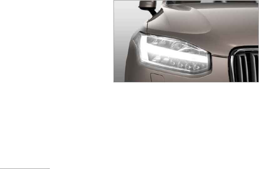
IntelliSafe—driver support
IntelliSafe is Volvo's philosophy regarding vehi-
cle safety. It encompasses a number of systems,
both standard and optional, that are designed to
help make driving and traveling in a Volvo safer.
Support
Systems that help make driving safer are an inte-
gral part of IntelliSafe. These include optional
features such as Adaptive Cruise Control* that
helps maintain a set distance to a vehicle ahead,
Park Assist Pilot*, which assists in parking the
vehicle, Cross Traffic Alert*, Blind Spot
Information*, etc.
Accident prevention
Systems such as City Safety are designed to
automatically apply the brakes in situations in
which the driver does not have time to react.
Lane Keeping Aid* alerts the drive if the vehicle
inadvertently crosses a lane's/road's side marker
line.
Protection
The vehicle is equipped with e.g., seat belt pre-
tensioners that pull the seat belts taut in critical
situations when there is a collision risk and
numerous airbags designed to help provide cush-
ioning if certain types of collisions should occur.
Related information
•Adaptive Cruise Control (ACC)* (p. 256)
•Park Assist Pilot (PAP)* (p. 306)
•High and low beam headlights (p. 137)
•Cross Traffic Alert (CTA)* (p. 323)
•Blind Spot Information (BLIS)* (p. 320)
•City Safety™ (p. 277)
•Driving lane assistance (p. 328)
•Airbag system (p. 84)
•Roll stability control (RSC) (p. 317)
•Seat belts (p. 60)
•General safety information (p. 56)
INTRODUCTION
}}
17
Sensus
Sensus is the core of your personal Volvo experi-
ence and provides information, entertainment
and features that make owning your vehicle eas-
ier.
This is Sensus
Sensus provides an intelligent interface and
Internet-connected service with an intuitive navi-
gation structure that offers access to relevant
information when it is needed, with minimal dis-
tractions.
Sensus also includes all of your vehicle's solu-
tions relating to entertainment, connecting to the
Internet, navigation and the user interface
between the driver and the vehicle. Sensus
makes communication between you, the vehicle
and the digital world around you possible.
||
INTRODUCTION
* Option/accessory, for more information, see Introduction.
18
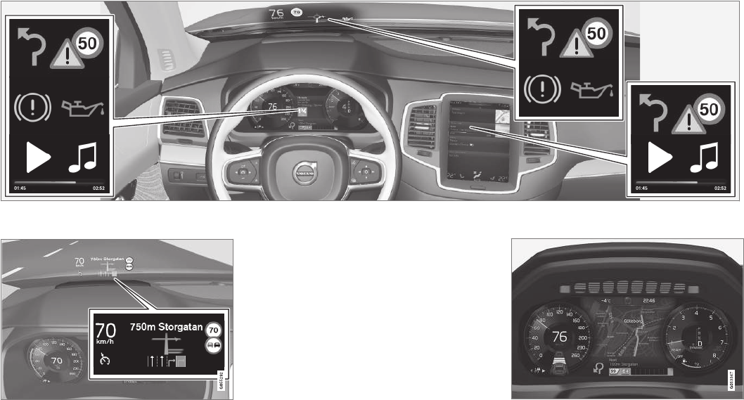
Information when it's needed, where it's needed
Information is presented in different displays depending on how it should be prioritized (generic illustration)
Head-up-display*
The head up-display presents types of informa-
tion that the driver should be aware of immedi-
ately, such as traffic warnings, speed information
and navigation. Road sign information and incom-
ing phone calls are also displayed here. The
head-up display is controlled from the right-side
steering wheel keypad and the center display.
Instrument panel
12" instrument panel
INTRODUCTION
* Option/accessory, for more information, see Introduction. 19
8" instrument panel
The instrument panel displays information such
as speed, an incoming phone call or the track
that is currently playing. It is controlled using both
steering wheel keypads.
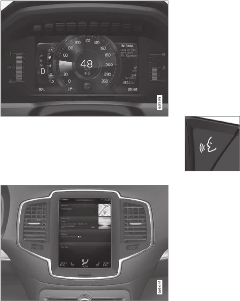
Center display
Many of the vehicle's main functions are con-
trolled from the center display, a touchscreen that
reacts to taps or other gestures. The number of
physical buttons is thereby minimized. The screen
can be operated with or without gloves.
The center display is used to control e.g., the cli-
mate and infotainment systems and to adjust the
power seats*. The information shown here can be
dealt with by the driver or the front seat passen-
ger.
Voice control system
The voice control system ena-
bles the driver to operate cer-
tain vehicle functions without
removing his/her hands from
the steering wheel and it
understands natural speech.
Use voice commands to e.g.,
play a track on the infotainment system, make a
phone call, raise the passenger compartment
temperature or to read a text message.
For additional information about all of the func-
tions/system, see the respective articles in the
on-board owner's manual or the printed supple-
ment.
Related information
•Using the center display (p. 45)
•Center display overview (p. 28)
•Navigating in the center display's views
(p. 38)
•Head-up display (HUD)* (p. 113)
•Instrument panel (p. 123)
•Voice control (p. 116)
INTRODUCTION
20
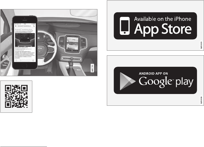
Owner's manual in mobile devices
Owner's information mobile app1 can be down-
loaded from the App Store and Google Play and
is adapted for both cell phones and tablets.
These apps also contain videos and interior/
exterior hotspot views of the vehicle that you can
click on for additional information.
This QR code will take you
directly to the app or you can
search for "Volvo manual" in
the App Store or Google Play.
The app contains videos and exterior/interior
views of the vehicle with certain components/
functions highlighted in hotspots, which lead
directly to related information. It is easy to navi-
gate between the various categories and articles
and the contents are searchable.
The mobile app is available at the App Store and Google
Play
Related information
•Using the owner's manual (p. 49)
•Additional information about your vehicle
(p. 14)
1Certain models and mobile devices
INTRODUCTION
}}
21
Options, accessories and the On-
board Diagnostic (OBDII) socket
We strongly recommend that Volvo owners
install only genuine, Volvo-approved accesso-
ries, and that accessory installations be per-
formed only by a trained and qualified Volvo
service technician.
Optional or accessory equipment described in
this manual is indicated by an asterisk.
Optional or accessory equipment may not be
available in all countries or markets. Please note
that some vehicles may be equipped differently,
depending on special legal requirements.
Contact your Volvo retailer for additional informa-
tion.
NOTE
•Do not export your Volvo to another
country before investigating that coun-
try's applicable safety and exhaust emis-
sion requirements. In some cases it may
be difficult or impossible to comply with
these requirements. Modifications to the
emission control system(s) may render
your Volvo not certifiable for legal opera-
tion in the U.S., Canada and other coun-
tries.
•All information, illustrations and specifica-
tions contained in this manual are based
on the latest product information availa-
ble at the time of publication. Please note
that some vehicles may be equipped dif-
ferently, depending on market-specific
adaptations or special legal requirements.
Optional equipment described in this
manual may not be available in all mar-
kets.
•Some of the illustrations shown are
generic and are intended as examples
only, and may not depict the exact model
for which this owner's information is
intended.
•Volvo reserves the right to make model
and product changes at any time, or to
change specifications or design without
notice and without incurring obligation.
WARNING
If your vehicle is involved in an accident,
unseen damage may affect its drivability and
safety.
WARNING
CALIFORNIA proposition 65
Engine exhaust, some of its constituents, and
certain vehicle components contain or emit
chemicals known to the state of California to
cause cancer, and birth defects or other
reproductive harm. In addition, certain fluids
contained in vehicles and certain products of
component wear contain or emit chemicals
known to the State of California to cause can-
cer, and birth defects or other reproductive
harm.
WARNING
Certain components of this vehicle such as air
bag modules, seat belt pretensioners, adap-
tive steering columns, and button cell batter-
ies may contain Perchlorate material. Special
handling may apply for service or vehicle end
of life disposal.
See www.dtsc.ca.gov/hazardouswaste/
perchlorate.
•Genuine Volvo accessories are tested to
ensure compatibility with the performance,
safety, and emission systems in your vehicle.
Additionally, a trained and qualified Volvo
||
INTRODUCTION
22
service technician knows where accessories
may and may not be safely installed in your
Volvo. In all cases, please consult a trained
and qualified Volvo service technician before
installing any accessory in or on your vehicle.
•Accessories that have not been approved by
Volvo may or may not be specifically tested
for compatibility with your vehicle. Addition-
ally, an inexperienced installer may not be
familiar with some of your car's systems.
•Any of your car's performance and safety
systems could be adversely affected if you
install accessories that Volvo has not tested,
or if you allow accessories to be installed by
someone unfamiliar with your vehicle.
•Damage caused by unapproved or improperly
installed accessories may not be covered by
your new vehicle warranty. See your Warranty
and Service Records Information booklet for
more warranty information. Volvo assumes no
responsibility for death, injury, or expenses
that may result from the installation of non-
genuine accessories.
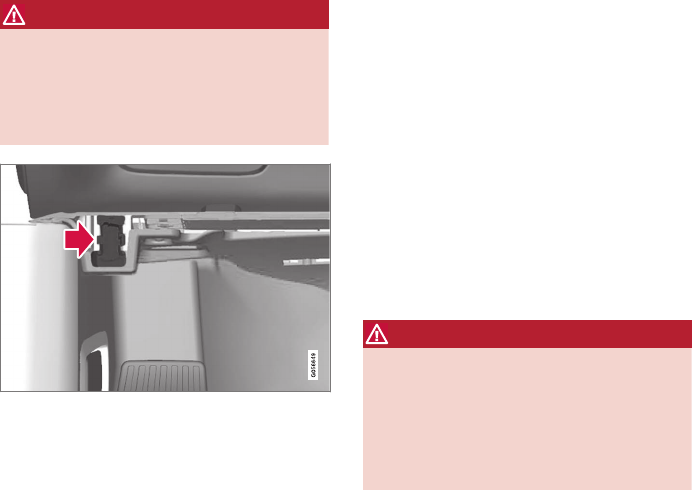
Connecting equipment to the On-board
Diagnostic (OBDII) socket
WARNING
Volvo Cars takes no responsibility for the con-
sequences of connecting non-authorized
equipment to the On-board Diagnostic
(OBDII) socket. This socket should only be
used by a trained and qualified Volvo service
technician.
The diagnostic socket OBDII under the dashboard on
the driver's side
Owner's information
Complete on-board digital owner's information is
available on the center display, as a mobile app
and on Volvo's support website.
The printed owner's manual in the glove compart-
ment is an excerpt from the digital information
and contains important texts, the latest updates
and instructions that can be useful in situations
where it is not practical to read the information
on the screen.
Changing the language used for the on-board
information could mean that some of the infor-
mation displayed may not comply with national or
local statutes and regulations.
If the content of the on-board digital informa-
tion and the printed manual differ, the printed
information always has precedence.
WARNING
The driver is always responsible for operating
the vehicle in a safe manner and adhering to
current laws and traffic regulations.
It is also important that the vehicle be oper-
ated, maintained and serviced according to
Volvo's recommendations/instructions in the
owner's manual.

INTRODUCTION
}}
23
Related information
•Owner's manual in mobile devices (p. 20)
•Navigating in the digital owner's manual
(p. 52)
•On-board digital owner's manual (p. 51)
Driver distraction
Please keep the following warnings in mind
when operating/servicing your vehicle.
A driver has a responsibility to do everything pos-
sible to ensure his or her own safety and the
safety of passengers in the vehicle and others
sharing the roadway. Avoiding distractions is part
of that responsibility.
Driver distraction results from driver activities that
are not directly related to controlling the vehicle
in the driving environment. Your new Volvo is, or
can be, equipped with many feature-rich enter-
tainment and communication systems. These
include hands-free cellular telephones, navigation
systems, and multipurpose audio systems. You
may also own other portable electronic devices
for your own convenience. When used properly
and safely, they enrich the driving experience.
Improperly used, any of these could cause a dis-
traction.
For all of these systems, we want to provide the
following warning that reflects the strong Volvo
concern for your safety. Never use these devices
or any feature of your vehicle in a way that dis-
tracts you from the task of driving safely. Distrac-
tion can lead to a serious accident. In addition to
this general warning, we offer the following guid-
ance regarding specific newer features that may
be found in your vehicle:
WARNING
•Never use a hand-held cellular telephone
while driving. Some jurisdictions prohibit
cellular telephone use by a driver while
the vehicle is moving.
•If your vehicle is equipped with a naviga-
tion system, set and make changes to
your travel itinerary only with the vehicle
parked.
•Never program your audio system while
the vehicle is moving. Program radio pre-
sets with the vehicle parked, and use your
programmed presets to make radio use
quicker and simpler.
•Never use portable computers or per-
sonal digital assistants while the vehicle
is moving.
Accessory installation
•We strongly recommend that Volvo owners
install only genuine, Volvo-approved acces-
sories, and that accessory installations be
performed only by a trained and qualified
Volvo service technician.
•Genuine Volvo accessories are tested to
ensure compatibility with the performance,
safety, and emission systems in your vehicle.
Additionally, a trained and qualified Volvo
service technician knows where accessories
may and may not be safely installed in your
Volvo. In all cases, please consult a trained

||
INTRODUCTION
24
and qualified Volvo service technician before
installing any accessory in or on your vehicle.
•Accessories that have not been approved by
Volvo may or may not be specifically tested
for compatibility with your vehicle. Addition-
ally, an inexperienced installer may not be
familiar with some of your car's systems.
•Any of your car's performance and safety
systems could be adversely affected if you
install accessories that Volvo has not tested,
or if you allow accessories to be installed by
someone unfamiliar with your vehicle.
•Damage caused by unapproved or improperly
installed accessories may not be covered by
your new vehicle warranty. See your Warranty
and Service Records Information booklet for
more warranty information. Volvo assumes no
responsibility for death, injury, or expenses
that may result from the installation of non-
genuine accessories.
WARNING
The driver is always responsible for operating
the vehicle in a safe manner and for comply-
ing with current statutes and regulations.
It is also essential to maintain and service the
vehicle according to Volvo's recommendations
as stated in the owner's information and the
service and warranty booklet.
If the on-board information differs from the
printed owner's manual, the printed informa-
tion always takes precedence.
Related information
•Volvo Structural Parts Statement (p. 24)
Volvo Structural Parts Statement
Volvo has always been and continues to be a
leader in automotive safety.
Volvo engineers and manufactures vehicles
designed to help protect vehicle occupants in the
event of a collision.
Volvos are designed to absorb the impact of a
collision. This energy absorption system including,
but not limited to, structural components such as
bumper reinforcement bars, bumper energy
absorbers, frames, rails, fender aprons, A-pillars,
B-pillars and body panels must work together to
maintain cabin integrity and protect the vehicle
occupants.
The supplemental restraint system including but
not limited to air bags, side curtain air bags, and
deployment sensors work together with the
above components to provide proper timing for
air bag deployment.
Due to the above, Volvo Cars of North America
does not support the use of aftermarket, alterna-
tive or anything other than original Volvo parts for
collision repair.
In addition Volvo does not support the use or re-
use of structural components from an existing
vehicle that has been previously damaged.
Although these parts may appear equivalent, it is
difficult to tell if the parts have been previously
replaced with non-OE parts or if the part has
been damaged as a result of a prior collision. The
INTRODUCTION
}}
25
quality of these used parts may also have been
affected due to environmental exposure.
Related information
•Crash event data (p. 25)
•Contacting Volvo (p. 14)
Crash event data
This vehicle is equipped with an event data
recorder (EDR). The main purpose of an EDR is
to record, in certain crash or near crash-like sit-
uations, such as an air bag deployment or hitting
a road obstacle, data that will assist in under-
standing how a vehicle's systems performed.
The EDR is designed to record data related to
vehicle dynamics and safety systems for a short
period of time, typically 30 seconds or less. The
EDR in this vehicle is designed to record such
data as:
•How various systems in your vehicle were
operating;
•Whether or not the driver and passenger
safety belts were buckled/fastened;
•How far (if at all) the driver was depressing
the accelerator and/or brake pedal; and,
•How fast the vehicle was traveling.
These data can help provide a better understand-
ing of the circumstances in which crashes and
injuries occur.
EDR data are recorded by your vehicle only if a
non-trivial crash situation occurs; no data are
recorded by the EDR under normal driving condi-
tions and the EDR never registers who is driving
the vehicle or the location of a crash or a near
crash-like situation. However, other parties, such
as law enforcement, could combine the EDR data
with the type of personally identifying data rou-
tinely acquired during a crash investigation. To
read data recorded by an EDR, special equipment
is required, and access to the vehicle or the EDR
is needed.
Furthermore, your vehicle is equipped with a
number of computers whose task is to continu-
ously control and monitor the vehicle’s operation.
They can also register some of this information
during normal driving conditions, most importantly
if they detect a fault relating to the vehicle’s oper-
ation and functionality or upon activation of the
vehicle’s active safety systems (e.g. City Safety
and the auto-brake function). Some of the regis-
tered information is required by technicians when
carrying out service and maintenance to enable
them to diagnose and rectify any faults that have
occurred in the vehicle and to enable Volvo to ful-
fill legal and other regulatory requirements. Infor-
mation thus registered in the vehicle is registered
in the vehicle’s computers until the vehicle is
serviced or repaired. In addition to the above, the
registered information may – on an aggregated
basis – be used for research and product devel-
opment purposes in order to continuously
improve the safety and quality of Volvo vehicles.
For additional information, contact:
In the United States
Volvo Cars of North America, LLC
Customer Care Center
1 Volvo Drive, P.O. box 914
INTRODUCTION
26
Rockleigh, New Jersey 07647
1-800-458-1552
www.volvocars.com/us
In Canada
Volvo Cars of Canada
National Customer Service
9130 Leslie Street
Richmond Hill, Ontario L4B 0B9
1-800-663-8255
www.volvocars.com/ca
Volvo ID
A Volvo ID can be used to access a number of
on-line services2
Creating a Volvo ID
A Volvo ID can be created in two ways:
Using the Volvo ID app
1. If you have not already done so, download
the Volvo ID app from the Remote update
service.
2. Start the app and register a personal email
address.
3. Follow the instructions that will be sent auto-
matically to this email address.
> A Volvo ID has now been created and has
been automatically registered to the vehi-
cle. The Volvo ID services available can
now be used.
Using the Volvo On Call (VOC) app
1. Download the latest version of the VOC app
to your cell phone from e.g., the App Store,
Windows Phone or Google Play.
2. Start the app and create a Volvo ID on the
start page.
3. Register a personal email address and then
follow the instructions that will be sent auto-
matically to this address.
Registering your Volvo ID to the vehicle
If your Volvo ID was created using the Volvo On
Call mobile app, the ID has to be registered to
the vehicle:
1. With the vehicle connected to the Internet,
download the Volvo ID app from the Remote
update service in the center display's App
view. See also the article "Downloading,
updating and uninstalling apps."
2. Start the app and enter your Volvo ID.
2These services vary and may be subject to change. Consult your Volvo retailer.
INTRODUCTION
27
3. Follow the instructions that will be sent auto-
matically to the email address linked to your
Volvo ID.
> Your Volvo ID is now registered to the
vehicle and the Volvo ID services available
can be used.
Advantages of having a Volvo ID
•Only one user name and password are
required to access online services.
•If you change a user name or password for
one of the online service (e.g., VOC), it/they
will also be automatically changed for the
other services.
Related information
•Downloading, updating and uninstalling apps
(p. 413)
•Connecting to the Internet (p. 410)
INTRODUCTION
28
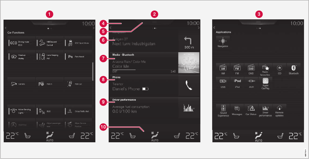
Center display overview
Many of the vehicle's functions are controlled
from the center display.
Three of the center display's basic views. Swipe to the right/left to access the Function/App view (generic illustration)

INTRODUCTION
* Option/accessory, for more information, see Introduction. 29
Function view: vehicle functions can be acti-
vated/deactivated by tapping. Certain func-
tions are called "trigger functions", which
open settings windows, e.g., Camera and
parking functions. Settings for the head-up
display* are also started from Function view
but the actual interaction is controlled from
the steering wheel keypad buttons and the
instrument panel.
Home view: the initial view shown when the
center display is started.
App (Application) view: shows apps that have
been downloaded (third-party apps) as well
as ones for integrated functions such as FM
radio. Tap an icon to open the app.
Status bar: vehicle activities are shown at the
top of the screen. Network/connection infor-
mation is shown on the left side of the bar.
Media-related information, the clock and
information about background activities are
shown to the right.
Top view: pull down the tab to open Top view.
From here, you can access Settings,
Owner's manual and stored messages.
Navigation: leads to map navigation. Tap the
sub-view to expand it.
Media: the most recently used media-related
apps. Tap the sub-view to expand it.
Phone: used to access phone-related func-
tions. Tap the sub-view to expand it.
The extra sub-view: the most recently used
apps/vehicle functions that do not belong in
any of the other sub-views are listed here.
Tap the sub-view to expand it.
Climate bar: information and direct access to
settings such as temperature, seat heating*
and blower speed. Tap the symbol at the
center of the Climate bar to open Climate
view for additional settings.
Related information
•Using the center display (p. 45)
•Function view buttons (p. 36)
•Symbols in the center display status bar
(p. 43)
•Settings view (p. 107)
•Media player (p. 399)
•Phone (p. 393)
•Climate system controls in the center display
(p. 178)
•Cleaning the center display (p. 539)
INTRODUCTION
30
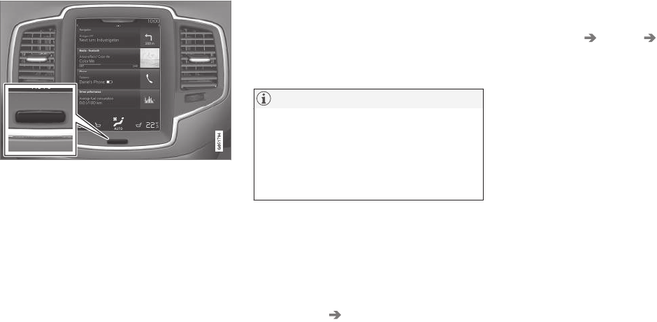
Changing center display settings
The center display activates automatically when
the driver's door is opened. Settings can be
made for e.g., sounds, background and themes.
Turning off and reactivating the center
display
Home button for the center display
When the center display is turned off, the screen
goes dark to avoid disturbing the driver. However,
the climate bar remains visible and apps or other
functions connected to the display remain active.
1. Press and hold the Home button below the
screen.
> The screen will go dark. However, the cli-
mate bar remains visible and apps or
other functions connected to the display
remain active. The screen can also be
cleaned while it is turned off.
2. Reactivate by pressing the Home button
briefly.
> The view that was displayed when the
screen was turned off will be displayed
again.
NOTE
•The display cannot be turned off while a
message requiring action is on the
screen.
•The display turns off automatically when
the ignition is switched off and the driv-
er's door is opened.
Turning off or changing the volume of
center display sounds
System sounds in the center display can be
turned off or their volume can be changed:
1. Tap Settings in the center display's Top
view.
2. Tap Sound System Volumes.
3. Pull the control under Screen Touch to the
desired level to change volume or turn off
the sound for tapping the screen or Keypad
Touch.
Changing the screen's appearance
(theme)
1. Tap Settings in the center display's Top
view.
2. Tap My Car Displays Themes.
3. Select a theme, e.g., Minimalistic or
Chrome Rings.
In addition, the settings: Normal and Bright can
also be selected. For Normal, the screen's back-
ground is dark and the text is light. This is the
default setting. If Bright is selected, the back-
ground will be light and the text will be dark,
which can increase readability in strong ambient
lighting.
These alternatives are always available and do
not shift automatically according to changes in
ambient lighting.
Related information
•Using the center display (p. 45)
•Sensus (p. 17)
•Settings view (p. 107)
•Cleaning the center display (p. 539)
INTRODUCTION
}}
31
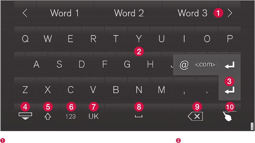
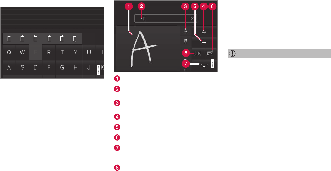
Using the center display keyboard
A keyboard can be used on the center display to
enter characters and search for e.g., destina-
tions using the navigation system, adding con-
tacts in phone book, etc. It is also possible to
use handwriting on the screen.
Entering text using the keyboard
The keyboard will only appear at the bottom of
the center display in situations when it is possible
to write on the screen.
||
INTRODUCTION
32
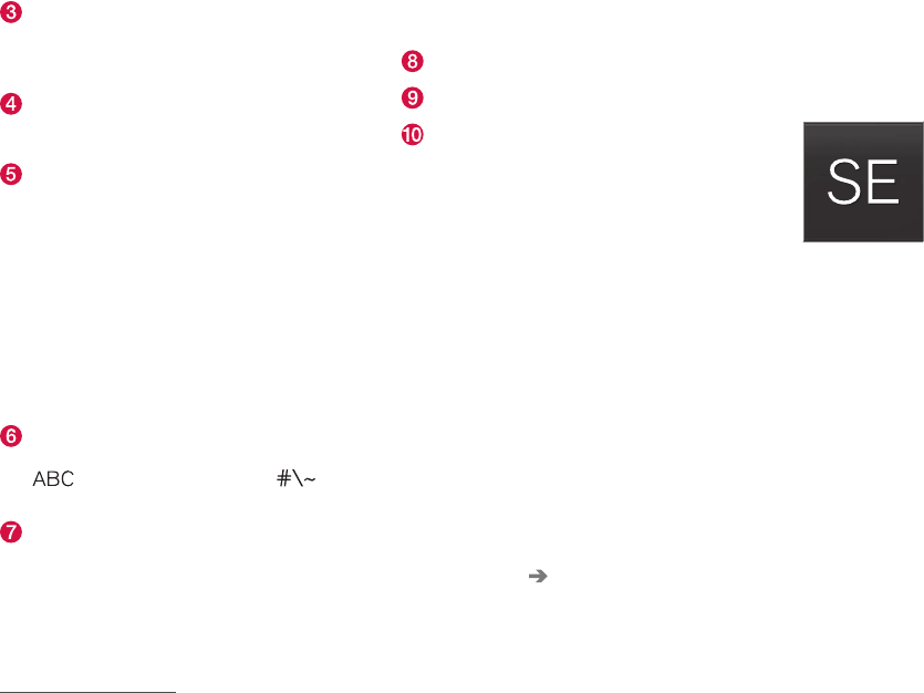
Keyboard function buttons (the appearance may vary depending on language settings, context, etc.)
Field for possible search hits. The word
changes as new letters are added. Scroll in
the list using the left/right arrows. Tap a
word to select it. The keyboard may not sup-
port all language selections, in which case
this line on the screen will not be displayed.
The characters that can be entered are lan-
guage-dependent (see point 7). Tap a char-
acter to enter it.
INTRODUCTION
}}
33
Several buttons (depending on the context
for which the keyboard is being used) will be
displayed here. In certain cases, it can be
used to enter @, .com or to start a new line.
Press to hide the keyboard. In cases where
this is not possible, the button will not be dis-
played.
Tap once to enter one uppercase letter.
Double-tap for Caps lock (tap again to
return to lowercase letters). Letters entered
after the !, . and ? characters will automati-
cally be uppercase. The first letter in the text
field or in text fields intended for names,
addresses or company names will also auto-
matically be uppercase. The first letter in text
fields intended for passwords, web
addresses or email addresses will automati-
cally be lowercase unless upper case is
chosen.
Press to display the numbers that can be
entered. When numbers are displayed, tap
to resume entering text or to
enter special characters.
Tap to change the keyboard language (in this
example, UK English is the selected lan-
guage). The characters available will change
according to the selected language (2). This
button will only be displayed if several key-
board languages have been selected (see
the section "Changing keyboard languages"
below). Tap to display a list of possible lan-
guages and tap a language to use it.
Tap to enter blank spaces.
Tap to erase one character at a time.
Tap to enable handwriting. See the section
"Handwritten text" below.
Entering text and performing searches using the
keyboard are done somewhat differently in the
navigation system. See the section "Filtering des-
tination search results" below.
Tap the button above the keyboard to confirm the
text that has been entered (not shown in the
illustration). This button's appearance differs
depending on the context.
Changing keyboard languages
In order to change keyboard languages, they
must first be selected under Settings.
The keyboard language can be changed without
changing the language used for the other sys-
tems/menus in the vehicle.
1. Pull down the center display's Top view and
tap Settings.
2. Tap System Keyboard Layouts.
3. Select and one or more of the languages in
the list.
> The makes it possible to change the key-
board layout and characters available
depending on the language(s) selected.
When more than one language
has been selected, this button
(7)3 will appear on the key-
board.
To shift between keyboard languages:
1. Press and hold the button (7).
> A list will be displayed.
2. Tap the desired language. If more than four
languages have been selected in Settings,
scroll in the list.
> The keyboard layout and characters avail-
able will change to the selected language.
3In the example illustration, the button shows "UK".
||
INTRODUCTION
34
Special characters
To enter language-specific characters such as é
or è (if available):
1. Press and hold a character key.
> A box with available characters will open.
2. Tap the desired character. If none of the spe-
cial characters is selected, the key's initial
character will be entered.
Handwritten text
Tap button (10), see the overview illustration
above, to enter the handwriting mode.
Area for entering characters.
Text box where the characters entered in
area (1) appear.
Suggested characters. Scroll in the list if
necessary.
Blank spaces.
Tap to erase one character at a time.
Tap to return to the standard keyboard.
Press to hide the keyboard. In cases where
this is not possible, the button will not be dis-
played.
Tap to change the keyboard language.
Entering characters
1. Enter a handwritten character (1) using a fin-
gertip or by holding e.g., a pen near the
screen.
> Several character suggestions will appear
(3). The most likely character will be at the
top of the list.
CAUTION
Do not touch the screen with sharp objects
because this could cause scratches.
2. Continue entering characters.
> If no other choice is made, the character
at the top of the list will be used. Tap one
of the other characters in the list to use it
instead.
INTRODUCTION
35
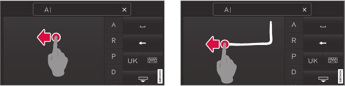
Erasing/changing handwritten characters
Erase a character by swiping over the handwriting area
(1)
Characters can be erased/changed in several
ways:
•Tap the desired character in the list (3).
•Tap button (5) to erase the character and
start again.
•Sweep horizontally from right to left over the
handwriting area (1). Erase several charac-
ters by swiping over the area several times.
•Tap the "x" in the text box (2) to delete all
characters.
New lines
Create a new line by drawing above the characters as
shown in the illustration
Related information
•Using the center display (p. 45)
•Center display overview (p. 28)
•Navigating in the center display's views
(p. 38)
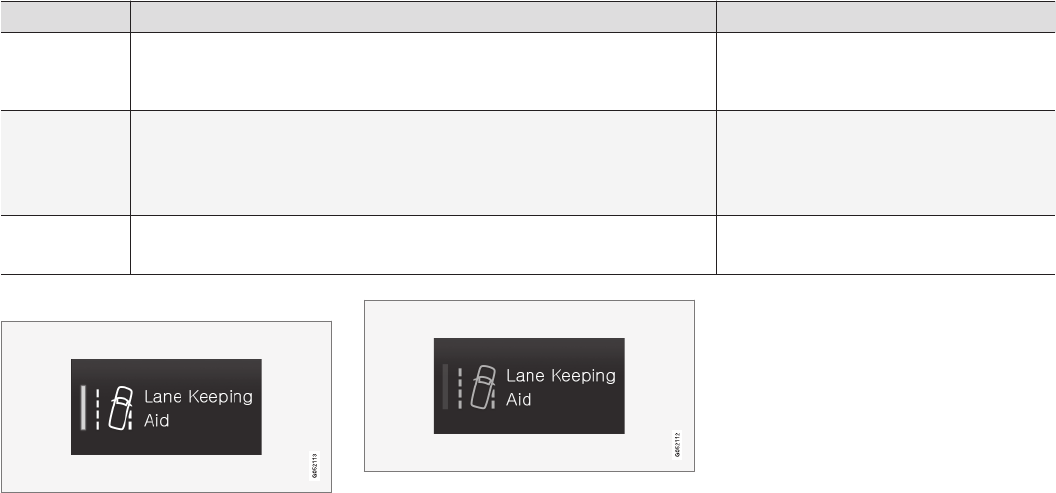
INTRODUCTION
36
Function view buttons
The Function view, which is one of the center
display's basic views, contains all of the vehicle's
on-screen function buttons. From the Home
view, swipe from left to right on the screen to
come to the Function view.
Different types of buttons
There are three different types of vehicle function
buttons as listed in the following table.
Type of button Functions Vehicle function affected
Function buttons Have On/Off modes.
An LED indicator light to the left of the button's icon will illuminate when a function is
active. Press the button to turn the function on or off.
Most of the buttons in the function view are
function buttons.
Start buttons Do not have On/Off modes.
Pressing a start button opens a function's window, e.g., a window for adjusting the
driver's seat.
•Camera.
•Headrest fold.
•Functions for folding down a seat.
•Head-up display adjustments.
Parking buttons Have On/Off and scanning modes.
Similar to function buttons but have an additional parking scanning mode.
•Park In.
•Park Out.
Button modes
A function is activated (on) when the LED indicator is
green
A function is deactivated (off) when the LED indicator is
off
When a function or parking button's LED indica-
tor is green, the function is activated. When a
function is initially activated, an additional text will
be displayed (certain functions only) in the button
for approx. 5 seconds, after which the button will
be displayed with the LED indicator illuminated.
Press the button briefly to deactivate the func-
tion.
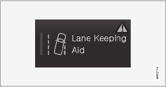
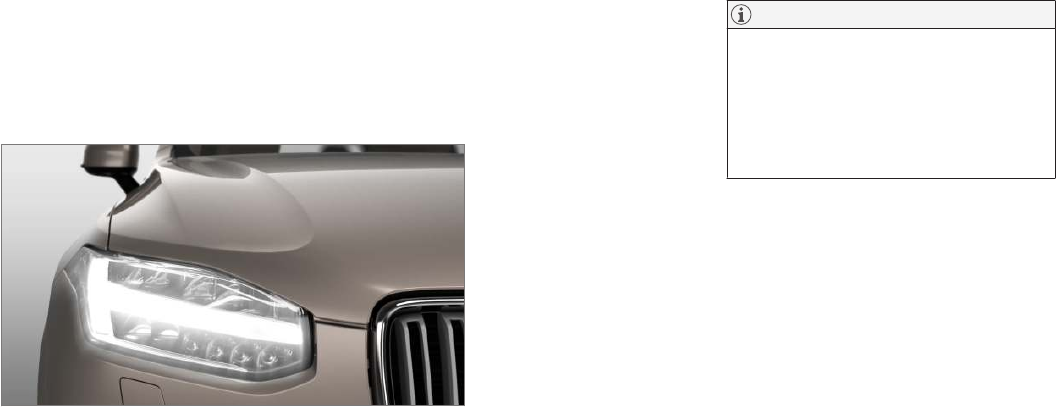
INTRODUCTION
38
Navigating in the center display's
views
There are 5 different basic views in the center
display: Home view, Top view, Climate view, App
view and Function view. The display is activated
automatically when the driver's door is opened.
Home view
Home view is displayed when the screen is acti-
vated. It consists of four sub-views: Navigation,
Media, Phone and an extra sub-view. The extra
sub-view contains the most recently used app/
vehicle function that is not related to the other
three sub-views. For example, if the most recently
used app/vehicle function is a music app, the
Media sub-view will be displayed.
The sub-views display brief information about the
respective apps.
The first time the vehicle is started, some of the
Home view's sub-views will not contain any infor-
mation.
NOTE
•In Home view's standard mode (reached
by pressing the Home button briefly), an
animation explaining how to access the
different views will be shown on the
screen.
•Some functions may be disabled when
the vehicle is moving.
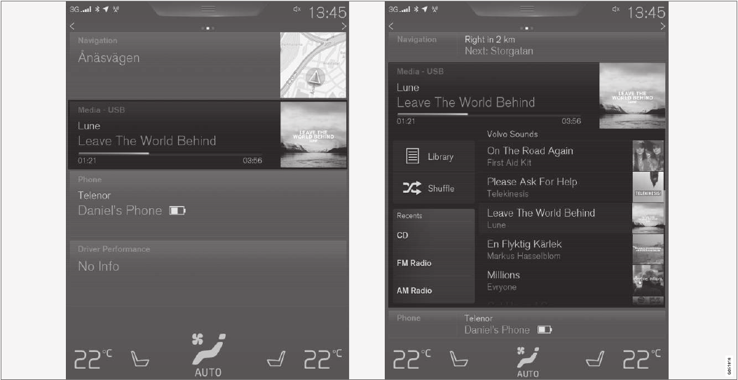
INTRODUCTION
}}
39
Expanding/minimizing a sub-view
The Media sub-view shown minimized (left) and expanded (right)
•To expand a sub-view, tap the screen any-
where in the sub-view to access the respec-
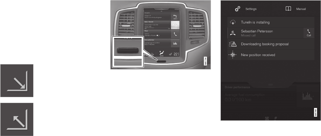
||
INTRODUCTION
40
tive app's basic functions. When a sub-view
is expanded, the Home view's fourth sub-
view will temporarily not be displayed.
•To minimize a sub-view, tap anywhere on the
screen.
Opening/closing a sub-view in full-screen
mode
The extra sub-view and the Navigation sub-view
can be opened in full-screen mode to show addi-
tional information and possible settings.
In expanded mode, open the
app in full-screen mode by tap-
ping the symbol.
Tap on the symbol or the Home
button below the screen to
return to the expanded view.
It is always possible to return to Home view by
pressing the Home button. Press the Home but-
ton twice to return to Home view's standard view
from full-screen.
Home button for the center display
Status bar
Current vehicle activities are shown in the status
bar at the top of the screen. Network and con-
nection information is shown to the left. Brief
information about currently running apps and the
clock are shown to the right.
Top view
The top view has a tab at the center of the status
bar. Pull down (expand) the Top view by swiping
the tab downward.
Top view when expanded
Top view provides access to:
•Settings
•Owner's manual
•The vehicle's stored messages
To leave (minimize) Top view, tap the screen out-
side of this view or tap at the bottom of Top view
and swipe upward. The views behind will become
visible again. Top view is not available when the
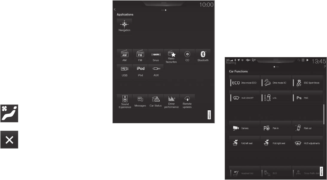
INTRODUCTION
}}
41
ignition is being started/switched off or when a
message is displayed on the screen.
Going to Top view from an app
To pull down Top view when an app is running
(e.g., FM radio):
•Tap FM Radio Settings to display these
settings.
•Tap Owner's manual to open an article
related to the specific app.
This applies only to your vehicle's factory-
installed apps. This is not possible for third-
party apps that have been downloaded.
Climate view
The climate bar, where the most common climate
system settings can be made, is located at the
bottom of the screen and is always visible.
Tap the symbol at the center of the cli-
mate bar to open Climate view for
access to additional climate system
settings.
Tap the symbol to close Climate view
and return to a previous view.
App view
App view
Swipe the screen from right to left to access App
view from Home view. This displays factory-instal-
led apps such as FM as well as any apps that
have been downloaded. Brief information will be
displayed for certain apps, for example missed
phone calls, etc.
Tap an app to open it.
When applicable, swipe downward to scroll in the
list of apps (depending on the number of apps
currently running).
To move an app, press and hold it. It will become
slightly bigger and transparent and can then be
dragged to the desired position and released.
Return to Home view by swiping the screen from
left to right or by pressing the Home button.
Function view
Function view with vehicle function buttons
||
INTRODUCTION
42
Swipe the screen from left to right to access
Function view from Home view. From Function
view, you can activate/deactivate various vehicle
functions such as Drive Modes, Speed limit
adaptation and Park Assist.
When applicable, swipe upward to scroll in the list
of functions (depending on the number of func-
tions).
Activate/deactivate a function by tapping its but-
ton. Certain functions will open in their own win-
dows.
To move a function button, press and hold it. It
will become slightly smaller and transparent and
can then be dragged to the desired position and
released.
Related information
•Using the center display (p. 45)
•Center display overview (p. 28)
•Function view buttons (p. 36)
•Symbols in the center display status bar
(p. 43)
•Changing settings in different types of apps
(p. 44)
•Climate system controls (p. 178)
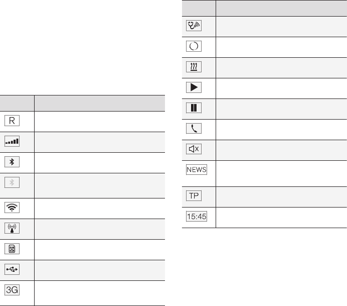
INTRODUCTION
43
Symbols in the center display status
bar
The following table provides an overview of the
symbols used in the center display's status bar.
The status bar shows current vehicle activities
and in certain cases, also their status. Due to lim-
ited space in the status bar, not all symbols will
be displayed at all times.
Symbol Meaning
Roaming activated.
Cell phone network signal strength.
Bluetooth device connected.
Bluetooth activated but no device
connected.
Connected to a Wi-Fi network.
Tethering activated. (Wi-Fi hotspot).
Vehicle modem activated.
Connected to the Internet via USB.
Type of cell phone connection (2G,
3G, etc.).
Symbol Meaning
Remote diagnostics active.
Action in progress.
PreconditioningA in progress.
Audio source being played.
Audio source paused.
Phone call in progress.
Audio source muted.
News broadcasts from current radio
stationB.
Traffic information being receivedB.
Clock.
AHybrid models only.
BNot available in all markets.
Related information
•Navigating in the center display's views
(p. 38)
•Indicator symbols in the instrument panel
(p. 121)
•Warning symbols in the instrument panel
(p. 131)
•Messages in the instrument panel and center
display (p. 146)
INTRODUCTION
44
Changing settings in different types
of apps
App view, which is one of the center display's
basic views, contains all of the vehicle's apps
(applications/programs). Access this view by
swiping the screen from right to left.
Basic apps
A number of apps are standard and are part of
Volvo Sensus, such as FM Radio, USB and CD.
To change settings in a basic app:
1. Open the app, for example Phone, either on
the home screen or full-screen from App
view.
2. Pull down Top view.
3. Tap Phone settings.
4. Change the desired settings and confirm.
5. Press the Home button, tap the screen out-
side of Top view or pull Top view up.
Third-party apps
Third party apps have to be selected and down-
loaded. In these apps, setting are made from
within the app, not from Top view.
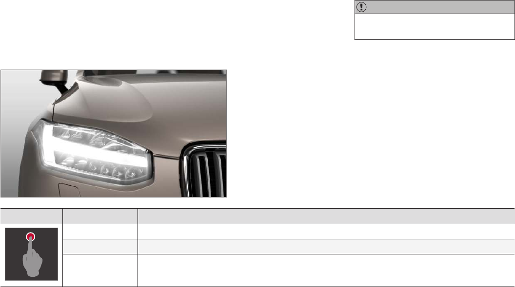
INTRODUCTION
}}
45
Using the center display
Many of the vehicle's functions can be con-
trolled and settings can be made from the
screen in the center console, referred to in this
owner's information as the center display, which
is a touchscreen.
Using the center display's touchscreen
functionality
Two people can interact with the screen at the
same time, e.g., to adjust the temperature for the
driver and passenger sides.
The screen reacts differently depending on
whether the user taps, drags or swipes on the
screen. This makes it possible to move between
views, mark objects, scroll in lists and move apps
by touching the screen in various ways. The fol-
lowing table lists the gestures that can be used
on the screen:
An infrared film on the screen enables it to react
if a finger is directly in front of the screen (but
not actually touching it). This makes it possible to
use the screen while wearing gloves.
CAUTION
Do not touch the screen with sharp objects
because this could cause scratches.
Procedure Gesture Result
Tap once. Marks an object, confirms a selection or activates a function.
Double-tap. Zooms in on an object such as a map.
Press and hold. "Grabs" an object so that it can be dragged. Press and hold on the screen and drag the object to the desired
position.
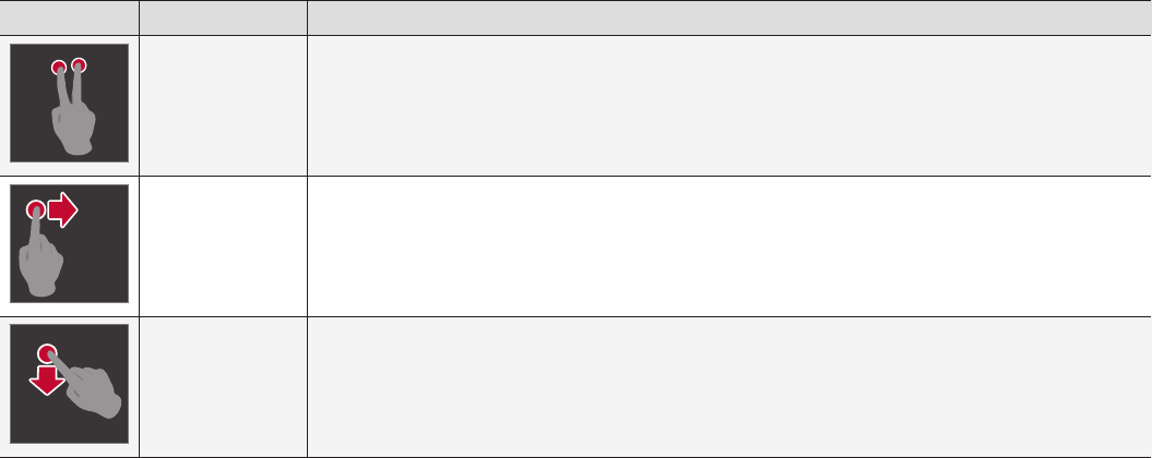
||
INTRODUCTION
46
Procedure Gesture Result
Tap with two fingers. Zooms out from an object such as a map.
Drag Moves between screen views, scrolls in a list, text or a view. Press and hold to drag apps or objects in a list.
Swipe Moves between screen views, scrolls in a list, text or a view
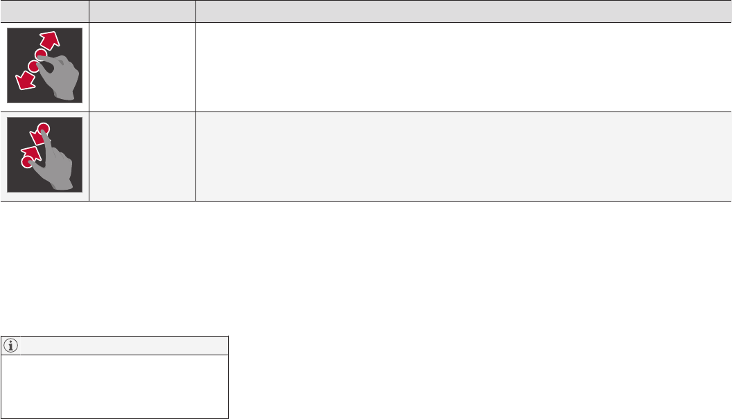
INTRODUCTION
}}
47
Procedure Gesture Result
Stretch Zooms in.
Pinch Zooms out.
Returning to Home view
1. Press the Home button briefly.
> The most recent Home view mode will be
displayed.
2. Press again briefly.
> All of the Home view's sub-views will
return to standard mode.
NOTE
From Home view's standard mode, press the
Home button to start animated on-screen
instructions describing how to display the var-
ious views.
Moving apps and vehicle function
buttons
Apps and function buttons can be moved and
organized in their respective views.
1. Press and hold an app/button.
> The app/button will change size and
become transparent. It can then be
moved.
2. Drag the app/button to an available position
in the view.
A maximum of 48 lines can be utilized for placing
apps/buttons. To move an app/button outside of
the visible view, drag it to the bottom of the view.
A new line will then be added where the app/
button can be placed (this line may not be visi-
ble). Swipe the screen to scroll up or down in the
view to display information that may be outside of
the view.
Scrolling in lists, articles or views
A scroll indicator on the screen shows that it is
possible to scroll up or down in the view. Press
the indicator and move it up or down or swipe up
or down anywhere in the view.
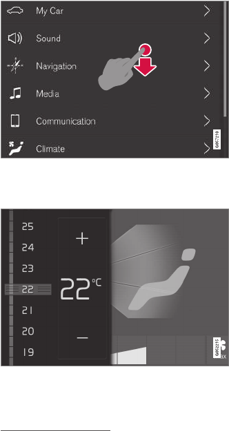
||
INTRODUCTION
48
The scroll indicator on the right side of the center dis-
play
Using center display controls
Temperature control4
Digital controls are available for many of the vehi-
cle's functions. For example, to set the tempera-
ture:
•Drag the control to the desired temperature
•Tap +/− to raise or lower the temperature
incrementally, or
•Tap the desired temperature on the control
Related information
•Navigating in the center display's views
(p. 38)
•Settings view (p. 107)
•Sensus (p. 17)
•Downloading, updating and uninstalling apps
(p. 413)
•Using the center display keyboard (p. 31)
4Generic illustration. The temperature in your vehicle may be set to degrees Fahrenheit.

INTRODUCTION
}}
49
Using the owner's manual
Reading your owner's manual is a good way of
familiarizing yourself with the features and sys-
tems in your vehicle.
On-board owner's manual
Reading the owner's manual is a good way to
become familiar with your vehicle and to learn to
utilize the features and functions that it offers.
Pay particular attention to the warnings provided.
Volvo reserves the right to make model changes
at any time, or to change specifications or design
without notice and without incurring obligation.
© Volvo Car Corporation
Printed owner's information
We advise keeping printed owner's information in
the vehicle for quick access to necessary infor-
mation and how to contact Volvo if help is
required.
Illustrations
Some of the illustrations used in your owner's
information may be generic and will give a gen-
eral view of a certain feature or function. For
example, some illustrations describing climate
system functions may display a temperature in
degrees Celsius but the same information applies
to Fahrenheit.
Options and accessories
Optional or accessory equipment described in
this manual is indicated by an asterisk.
Optional or accessory equipment may not be
available in all countries or markets. Please note
that some vehicles may be equipped differently,
depending on special legal requirements.
Contact your Volvo retailer for additional informa-
tion.
Footnotes
This owner's information contains supplementary
information indicated by an information symbol: 5.
Tap the symbol to open a window showing the
information.
Messages
There are several displays in the vehicle that
show messages generated by various systems
and functions in the vehicle. The appearance of
these texts differs slightly from normal texts (for
example: Phone, Accept).
Decals
There are various types of decals in the vehicle
whose purpose is to provide important informa-
tion in a clear and concise way. The importance
of these decals is explained as follows, in
descending order of importance.
Risk of injury
Black ISO symbols on a yellow warning back-
ground, white text/image on a black background.
Decals of this type are used to indicate potential
danger. Ignoring a warning of this type could
result in serious injury or death.
5Example of supplementary information
||
INTRODUCTION
50
Risk of damage to the vehicle
White ISO symbols and white text/image on a
black or blue warning background and space for
a message. If the information on decals of this
type is ignored, damage to the vehicle could
result.
Information
White ISO symbols and white text/image on a
black background. These decals provide general
information.
NOTE
The decals shown in the Owner’s Manual are
examples only and are not intended to be
reproductions of the decals actually used in
the vehicle. The purpose is to give an indica-
tion of how they look and their approximate
location in the vehicle. The applicable infor-
mation for your particular vehicle can be
found on the respective decals in the vehicle.
Types of lists
Procedures
Procedures (step-by-step instructions), or actions
that must be carried out in a certain order, are
arranged in numbered lists in this manual.
If there is a series of illustrations associated
with step-by-step instructions, each step in
the procedure is numbered in the same way
as the corresponding illustration.
Lists in which letters are used can be found
with series of illustrations in cases where the
order in which the instructions are carried out
is not important.
Arrows with or without numbers are used to
indicate the direction of a movement.
Arrows containing letters are used to indi-
cate movement.
If there are no illustrations associated with a
step-by-step list, the steps in the procedure are
indicated by ordinary numbers.
Position lists
Red circles containing a number are used in
general overview illustrations in which certain
components are pointed out. The corres-
ponding number is also used in the position
list's description of the various components.
Bullet lists
Bullets are used to differentiate a number of
components/functions/points of information that
can be listed in random order.
For example:
•Coolant
•Engine oil
Illustrations
Some of the illustrations and images shown in
the owner's manual are generic and may differ
slightly from the equipment in your vehicle
depending the level of instrumentation or market.
Related information
Related information offers references to articles
containing information associated with the infor-
mation that you are currently reading.
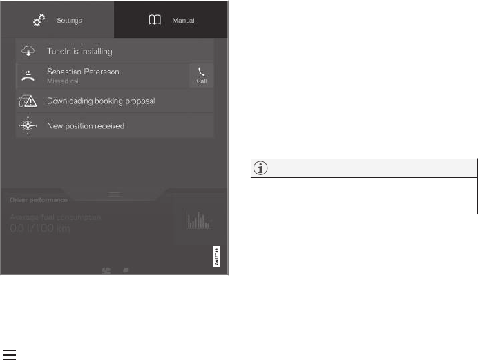
INTRODUCTION
51
Related information
•Owner's manual in mobile devices (p. 20)
•Additional information about your vehicle
(p. 14)
On-board digital owner's manual
When printed owner's information refers to digi-
tal owner's information, this is the on-board infor-
mation available in the vehicle's center display.
The digital on-board owner's manual is accessed from
the center display's Top view
There are a number of ways to find information in
the digital owner's manual, which can be
accessed from the manual's top menu by tapping
.
•Start: the on-board information's start page,
showing an introductory text.
•Categories: all articles sorted by category.
An article may be listed in several categories.
•Quick Guide: A selection of useful articles.
•Exterior: Exterior views of the vehicle in
which certain areas/components are high-
lighted as hotspots. Tap a hotspot to come to
a relevant article.
•Interior: Interior views of the vehicle in which
certain areas/components are highlighted as
hotspots. Tap a hotspot to come to a relevant
article.
•Favorites: Quick access to articles that have
been tagged as favorites.
NOTE
The on-board owner's information cannot be
accessed while the vehicle is moving.
Related information
•Navigating in the digital owner's manual
(p. 52)
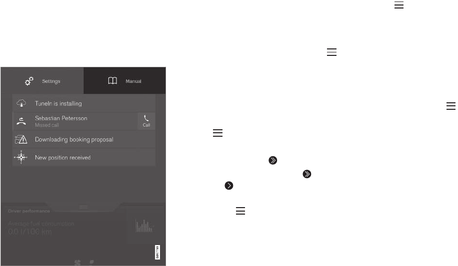
INTRODUCTION
52
Navigating in the digital owner's
manual
The digital on-board owner's manual is
accessed from the center display. The contents
are searchable and it is easy to navigate among
the varios sections.
The digital on-board owner's manual is accessed from
the center display's Top view
To open the digital owner's information, pull down
the center display's Top view and tap Owner's
manual.
There are several ways of finding information.
To access the owner's manual's menu, tap
in the upper bar.
Searching using categories
The articles in the owner's manual are structured
in main and sub-categories. The same article may
appear in several pertinent categories in order to
make them easier to find.
1. Tap followed by Categories.
> The main categories will be listed.
2. Tap a main category ( ).
>A list of sub-categories and ( ) and arti-
cles ( ) will be displayed.
3. Tap an article to open it. Tap the left arrow to
go back or to begin a new search.
Interior and exterior hotspots
Exterior and interior views of the vehicle where
certain components are pointed out are called
hotspots.
1. Tap followed by Exterior/Interior.
> Exterior/interior views will be displayed
with hotspots, which lead to relevant arti-
cles. Swipe the screen horizontally to
scroll among the views.
2. Tap a hotspot.
> The title of a relevant article will be dis-
played.
3. Tap the title to open the article. Tap the left
arrow to go back or to begin a new
search.
Quick Guide.
The heading Quick Guide in the owner's man-
ual's menu leads to a selection of articles that
may be helpful in familiarizing you with your vehi-
cle's most common features and functions.
These articles can also be found through catego-
ries but have been gathered here for quick
access. Tap an article to read it in its entirety.
Favorites
This is a list of articles that have been saved as
favorites. The most recently saved one will be at
the top of the list. Tap an article to read it in its
entirety.

INTRODUCTION
* Option/accessory, for more information, see Introduction. 53
Saving/deleting favorites
Save an article as a favorite by tapping the star
() at the upper right when an article is open.
The star symbol will be filled in ( ) when its arti-
cle has been saved as a favorite.
To delete a favorite, tap its star again.
Using the search function
1. Tap the magnifying glass icon ( ) in the
owner's manual's upper menu. A keyboard
will appear at the bottom of the screen.
2. Enter a word, e.g., "seat belt."
> Suggested articles will be displayed as
more characters are entered.
3. Confirm by tapping the article. To leave
search mode tap the up-arrow next to the
search box.
Related information
•On-board digital owner's manual (p. 51)
•Using the center display keyboard (p. 31)
Glass
Laminated glass
The windshield and panoramic roof* are made of
laminated glass, which is reinforced to help pre-
vent break-ins and to provide additional sound-
proofing. Laminated glass is optional for the
other side windows.
Laminated glass symbol6
Related information
•Laminated panoramic roof* (p. 102)
•Power windows (p. 104)
•Defrosting windows and mirrors (p. 186)
•Using sun shades (p. 107)
•Rearview mirror (p. 106)
•Power windows (p. 104)
•Head-up display (HUD)* (p. 113)
•Activating/deactivating the rain sensor
(p. 153)
•Windshield and headlight washers (p. 154)
•Tailgate window wiper and washer (p. 155)
Technician certification
In addition to Volvo factory training, Volvo sup-
ports certification by the National Institute for
Automotive Service Excellence (A.S.E.).
Certified technicians have demonstrated a high
degree of competence in specific areas. Besides
passing exams, each technician must also have
worked in the field for two or more years before a
certificate is issued. These professional techni-
cians are best able to analyze vehicle problems
and perform the necessary maintenance proce-
dures to keep your Volvo at peak operating con-
dition.
6This symbol is not shown on the windshield or panoramic roof.


SAFETY
SAFETY
56
General safety information
The vehicle is equipped with a number of safety
systems for the driver and passengers.
In the event of an accident, there are a number of
sensors in the vehicle that react and trigger
safety systems such as Roll Stability Control, air-
bags, seat belt pretensioners, etc., depending on
the severity of the collision. There are also
mechanical systems such as the Whiplash
Protection System.
Warning symbol in the instrument panel
The warning symbol in the instrument
panel illuminates when the ignition is in
mode II or higher. It will go out after
approx. 6 seconds if no faults are
detected in the airbag system.
WARNING
•If the SRS warning light stays on after the
engine has started or if it illuminates
while you are driving, have the vehicle
inspected by a trained and qualified Volvo
service technician as soon as possible.
•Never try to repair any component or part
of the SRS yourself. Any interference in
the system could cause malfunction and
serious injury. All work on these systems
should be performed by a trained and
qualified Volvo service technician.
If the dedicated warning symbol is not
functioning, the general warning sym-
bol will illuminate instead and the same
message will be displayed in the instru-
ment panel.
Related information
•Safety during pregnancy (p. 58)
•Seat belts (p. 60)
•Airbag system (p. 84)
•Safety mode (p. 83)
•Whiplash protection system (p. 59)
•Child safety (p. 64)
Occupant safety
Safety is Volvo's cornerstone.
Volvo's concern for safety
Our concern for safety dates back to 1927 when
the first Volvo rolled off the production line.
Three-point seat belts (a Volvo invention), safety
cages, and energy-absorbing impact zones were
designed into Volvo vehicles long before it was
fashionable or required by government regulation.
We will not compromise our commitment to
safety. We continue to seek out new safety fea-
tures and to refine those already in our vehicles.
You can help. We would appreciate hearing your
suggestions about improving automobile safety.
We also want to know if you ever have a safety
concern with your vehicle. Call us in the U.S. at:
1-800-458-1552 or in Canada at:
1-800-663-8255.
SAFETY
}}
57
Occupant safety reminders
How safely you drive doesn't depend on how old
you are but rather on:
•How well you see.
•Your ability to concentrate.
•How quickly you make decisions under
stress to avoid an accident.
The following suggestions are intended to help
you cope with the ever changing traffic environ-
ment.
•Never drink and drive.
•If you are taking any medication, consult your
physician about its potential effects on your
driving abilities.
•Take a driver-retraining course.
•Have your eyes checked regularly.
•Keep your windshield and headlights clean.
•Replace wiper blades when they start to
leave streaks.
•Take into account the traffic, road, and
weather conditions, particularly with regard to
stopping distance.
•Never send text messages while driving.
•Refrain from using or minimize the use of a
cell phone while driving.
Related information
•Recall information (p. 58)
•Reporting safety defects (p. 57)
Reporting safety defects
The following information will help you report any
perceived safety-related defects in your vehicle.
Reporting safety defects in the U.S.
If you believe that your vehicle has a
defect which could cause a crash or
could cause injury or death, you should
immediately inform the National High-
way Traffic Safety Administration
(NHTSA) in addition to notifying Volvo
Cars of North America, LLC. If NHTSA
receives similar complaints, it may open
an investigation, and if it finds that a
safety defect exists in a group of vehi-
cles, it may order a recall and remedy
campaign. However, NHTSA cannot
become involved in individual problems
between you, your retailer, or Volvo
Cars of North America, LLC. To contact
NHTSA, you may either call the Auto
Safety Hotline toll-free at
1-888-327-4236
(TTY: 1-800-424-9153) or write to:
NHTSA, U.S. Department of Transpor-
tation, Washington D.C. 20590.
You can also obtain other information
about motor vehicle safety from http://
www.safercar.gov, where you can also
enter your vehicle's VIN (Vehicle Identi-
fication Number) to see if it has any
open recalls.
Volvo strongly recommends that if your
vehicle is covered under a service cam-
paign, safety or emission recall or simi-
lar action, it should be completed as
soon as possible. Please check with
your local retailer or Volvo Cars of
North America, LLC if your vehicle is
covered under these conditions.
NHTSA can be reached at:
Internet:
http://www.nhtsa.gov
Telephone:
1-888-DASH-2-DOT
(1-888-327-4236).
Reporting safety defects in Canada
If you believe your vehicle has a defect that could
cause a crash or could cause injury or death, you
should immediately inform Transport Canada in
addition to notifying Volvo Cars of Canada Corp.
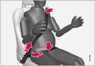
||
SAFETY
58
Transport Canada can be contacted at:
1-800-333-0510
Teletypewriter (TTY): 613 990-4500
Fax: 1-819-994-3372
Mailing Address: Transport Canada - Road
Safety, 80 rue Noël, Gatineau, (Quebec) J8Z 0A1
Related information
•Recall information (p. 58)
•Occupant safety (p. 56)
Recall information
On our website, select the tab YOUR VOLVO and
the heading RECALL INFORMATION will be dis-
played at the lower left side of the screen. Enter
your Vehicle Identification Number for your vehi-
cle (found at the base of the windshield). If your
vehicle has any open Recalls, they will be dis-
played on this page.
Volvo customers in Canada
For any questions regarding open recalls for your
vehicle, please contact your authorized Volvo
retailer. If your retailer is unable to answer your
questions, please contact Volvo Customer Rela-
tions at 905 695-9626, Monday through Friday,
8:30 A.M. to 5:00 P.M. EST or by e-mail at
vclcust@volvocars.com. You may also write us at:
Volvo Cars of Canada
National Customer Service
9130 Leslie Street, Suite 101
Richmond Hill, Ontario L4B 0B9
www.tc.gc.ca
Related information
•Occupant safety (p. 56)
•Reporting safety defects (p. 57)
Safety during pregnancy
The seat belt should always be worn during
pregnancy. However, it is crucial that it be worn
correctly.
The diagonal section should wrap over the shoul-
der then be routed between the breasts and to
the side of the belly. The lap section should lay
flat over the thighs and as low as possible under
the belly. It must never be allowed to ride upward.
Remove all slack from the belt and ensure that it
fits close to the body without any twists.
As a pregnancy progresses, pregnant drivers
should adjust their seats and steering wheel such
that they can easily maintain control of the vehi-
cle as they drive (which means they must be able
to easily operate the foot pedals and steering
wheel). Within this context, they should strive to
position the seat with as large a distance as pos-
sible between their belly and the steering wheel.

SAFETY
}}
* Option/accessory, for more information, see Introduction. 59
Related information
•Buckling and unbuckling seat belts (p. 61)
•Adjusting power front seats* (p. 159)
•Manually operated front seats (p. 158)
Whiplash protection system
The Whiplash protection system (WHIPS) con-
sists of specially designed hinges and brackets
on the front seat backrests designed to help
absorb some of the energy generated in a colli-
sion from the rear (when the vehicle is rear-
ended).
Function
In the event of certain rear-end collisions, the
hinges and brackets of the front seat backrests
are designed to change position slightly to allow
the backrest/head restraint to help support the
occupant's head before moving slightly rearward.
This movement helps absorb some of the forces
that could result in whiplash.
WARNING
•The WHIPS system is designed to sup-
plement the other safety systems in your
vehicle. For this system to function prop-
erly, the three-point seat belt must be
worn. Please be aware that no system
can prevent all possible injuries that may
occur in an accident.
•The WHIPS system is designed to func-
tion in certain collisions from the rear,
depending on the crash severity, angle
and speed.
WARNING
•Occupants in the front seats must never
sit out of position. The occupant's back
must be as upright as comfort allows and
be against the seat back with the seat
belt properly fastened.
•If your vehicle has been involved in a rear-
end collision, the front seat backrests
must be inspected by a trained and quali-
fied Volvo service technician, even if the
seats appear to be undamaged. Certain
components in the WHIPS system may
need to be replaced.
•Do not attempt to service any component
in the WHIPS system yourself.
WARNING
•Boxes, suitcases, etc. wedged behind the
front seats could impede the function of
the WHIPS system.
•If the rear seat backrests are folded
down, cargo must be secured to prevent
it from sliding forward against the front
seat backrests in the event of a collision
from the rear. This could interfere with
the action of the WHIPS system.
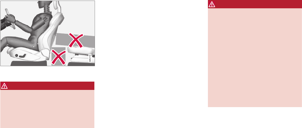
||
SAFETY
* Option/accessory, for more information, see Introduction.
60
Do not place any objects behind the front seats that
could impede the WHIPS function
WARNING
Any contact between the front seat backrests
and the folded rear seat or a rear-facing child
seat could impede the function of the WHIPS
system. If the rear seat is folded down, the
occupied front seats must be adjusted for-
ward so that they do not touch the folded rear
seat.
Related information
•General safety information (p. 56)
•Rear Collision Warning (RCW) (p. 282)
•Manually operated front seats (p. 158)
•Power front seats* (p. 159)
Seat belts
Seat belts should always be worn by all occu-
pants of your vehicle. Children should be prop-
erly restrained, using an infant, car, or booster
seat determined by age, weight and height.
Most states and provinces make it mandatory for
occupants of a vehicle to use seat belts.
Reversible seat belt pretensioners
Reversible seat belt pretensioners is a system in
the front seats that pulls the seat belts slightly
taut prior to a collision. This function helps posi-
tion the front seat occupants to help improve the
effects of other safety systems, e.g., the airbag
system.
Seat belt maintenance
Check periodically that the seat belts are in good
condition. Use water and a mild detergent for
cleaning. Check seat belt mechanism function as
follows: attach the seat belt and pull rapidly on
the strap.
WARNING
•Never repair the belt yourself; have this
work done by a trained and qualified
Volvo service technician only.
•Any device used to induce slack into the
shoulder belt portion of the three-point
belt system will have a detrimental effect
on the amount of protection available to
you in the event of a collision.
•The seat back should not be tilted too far
back. The shoulder belt must be taut in
order to function properly.
•Do not use child safety seats or child
booster cushions/backrests in the front
passenger's seat. We also recommend
that children who have outgrown these
devices sit in the rear seat with the seat
belt properly fastened.
Related information
•Buckling and unbuckling seat belts (p. 61)
•Door and seat belt reminders (p. 63)
•Seat belt pretensioners (p. 61)

SAFETY
}}
61
Seat belt pretensioners
The vehicle's seat belts are equipped with stand-
ard and electric pretensioners that can help pull
the seat belts taut in a critical situation or a colli-
sion. Some or all of the pretensioners will be
triggered in certain types of collisions, depend-
ing on the direction and severity of the impact.
Reversible seat belt pretensioners
Reversible seat belt pretensioners is a system in
the front seats that pulls the seat belts slightly
taut prior to a collision. This function helps posi-
tion the front seat occupants to help improve the
effects of other safety systems, e.g., the airbag
system.
Seat belt pretensioners in collisions
The seat belts are equipped with standard pre-
tensioners that are triggered according to the
severity of a collision.
Seat belt pretensioners in critical
situations
In addition to the standard pretensioners, the
seat belts in the front seats are also equipped
with electric pretensioners.
The pretensioners interact and can be triggered
along with the City Safety and Rear Collision
Warning systems. In critical situations such as
sudden braking, evasive maneuvers, etc., the seat
belt can be pulled taut by the pretensioner's
electric motor.
The electric pretensioner positions the occupant
in the seat to help reduce the risk of striking the
interior of the passenger compartment and
improves the effect of other safety systems such
as the airbags.
Resetting the electric pretensioners
When a critical situation has passed, the seat belt
and the electric pretensioner are reset automati-
cally.
If the seat belt should remain taut:
1. Stop the vehicle safely.
2. Unbuckle the seat belt and rebuckle it.
> The seat belt and the electric preten-
sioner will be reset.
Related information
•Seat belts (p. 60)
•Door and seat belt reminders (p. 63)
•Buckling and unbuckling seat belts (p. 61)
Buckling and unbuckling seat belts
Seat belts should be used by all occupants in
the vehicle when it is in motion.
Buckling a seat belt
1. Pull the belt out slowly. It should not be twis-
ted or turned.
NOTE
Each seat belt is equipped with a seat belt
retractor that will lock up in the following sit-
uations:
•if the belt is pulled out rapidly
•during braking and acceleration
•if the vehicle is leaning excessively
•when driving in turns
•if the Automatic Locking Retractor/Emer-
gency Locking Retractor (ALR/ELR) is
activated (each seat belt (except for the
driver's belt) is equipped with the
ALR/ELR function, which is designed to
help keep the seat belt taut. ALR/ELR
activates if the seat belt is pulled out as far
as possible. If this is done, a sound from
the seat belt retractor will be audible,
which is normal, and the seat belt will be
pulled taut and locked in place. This func-
tion is automatically disabled when the
seat belt is unbuckled and fully retracted).
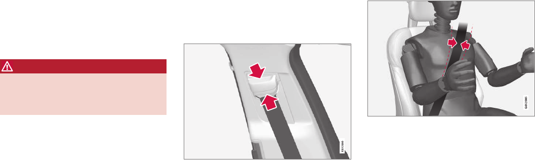
||
SAFETY
62
2. Insert the latch plate into the receptacle. The
seat belt retractor is normally "unlocked" and
you can move freely, provided that the shoul-
der belt is not pulled out too far.
> A distinct click will be audible.
WARNING
The seat belt latch plate should only be
inserted into its intended receptacle. Inserting
it into one of the other receptacles may pre-
vent it from functioning properly.
3. The height of the seat belts in the front seats
and outboard rear seating positions can be
adjusted. The height of the shoulder section
of the seat belt must be correctly adjusted.
Press the button and move the upper seat
belt anchor up or down.
Position it as high as possible so that the
shoulder section of the belt is across the seat
occupant's collarbone and not across the
throat.
The seat belt should be positioned over the shoulder
(not over the arm)
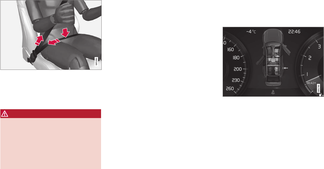
SAFETY
}}
63
4. Tighten the lap section of the seat belt by
pulling the diagonal section upward toward
the shoulder.
The lap section of the belt must be positioned low on the
hips (not pressing against the abdomen)
Make sure that the shoulder belt is rolled up
into its retractor and that the shoulder and
lap belts are taut.
WARNING
Never use a seat belt for more than one
occupant. Never wear the shoulder portion of
the belt under the arm, behind the back or
otherwise out of position. Such use could
cause injury in the event of an accident. As
seat belts lose much of their strength when
exposed to violent stretching, they should be
replaced after any collision, even if they
appear to be undamaged.
Unbuckling the seat belt
To remove the seat belt, press the red section on
the seat belt receptacle. Before exiting the vehi-
cle, check that the seat belt retracts fully after
being unbuckled. If necessary, guide the belt
back into the retractor slot.
Related information
•Door and seat belt reminders (p. 63)
•Seat belts (p. 60)
Door and seat belt reminders
The door and seat belt reminders are intended
to alert all occupants of the vehicle that their
seat belts should be buckled before the vehicle
begins to move or if a door, the hood, tailgate or
fuel filler door have not been closed properly.
Graphics in the instrument panel
Warning colors for doors/tailgate vary depending on the
vehicle's speed
The instrument panel graphic shows the seats
where seat belts are not buckled.
The same graphic also indicates if a door, the
hood, tailgate or fuel filler door is/are open.
This graphic disappears automatically after
approx. 30 seconds or if the if the O button on
the steering wheel keypad is pressed.
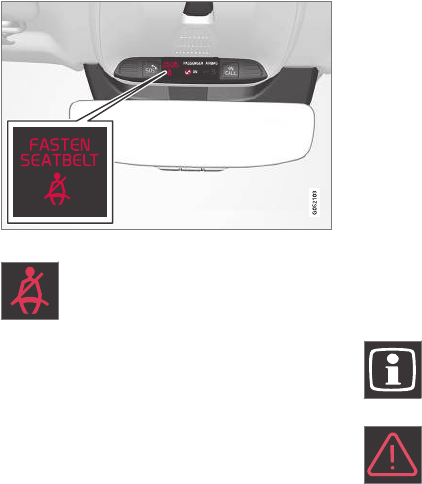
||
SAFETY
64
Seat belt reminder
Seat belt reminder light in ceiling console
The seat belt reminder consists of an
audible signal, an indicator light near
the rearview mirror and a symbol in the
instrument panel that alert all occu-
pants of the vehicle to buckle their seat belts.
The audible signal is speed-dependent and will
sound for several seconds.
If the driver's or a passenger's seat belt is not
buckled, this will be indicated in the instrument
panel.
Child seats are not included in the seat belt
reminder system.
Front seats
An audible signal and an indicator light will
remind the driver and front seat passenger to
buckle their seat belts.
Rear seats
The rear seat belt reminder has two functions.
•It indicates which seat belts are buckled in
the rear seats. This will also be displayed in
an instrument panel graphic.
•It also provides audio and visual reminders if
a rear seat belt is unbuckled while the vehi-
cle is in motion. The reminders will disappear
when the seat belt has been buckled again
or can be erased by pressing the O button
on the steering wheel keypad.
Door/hood/tailgate/fuel filler door
reminder
If a door, the hood, tailgate or fuel filler door
is/are not properly closed, this will be indicated in
a graphic in the instrument panel. Stop the vehi-
cle safely and close the source of the reminder.
If the vehicle is moving at a speed
under approx.6 mph (10 km/h), the
information symbol will illuminate in the
instrument panel.
At speeds above approx. 6 mph
(10 km/h), the warning symbol will illu-
minate in the instrument panel.
Related information
•Seat belts (p. 60)
•Buckling and unbuckling seat belts (p. 61)
Child safety
Children should always be seated safely when
traveling in the vehicle.
General information
Volvo recommends the proper use of restraint
systems for all occupants including children.
Remember that, regardless of age and size, a
child should always be properly restrained in a
vehicle.
Your vehicle is also equipped with ISOFIX/
LATCH attachments, which make it more conven-
ient to install child seats.
Some restraint systems for children are designed
to be secured in the vehicle by lap belts or the
lap portion of a lap-shoulder belt. Such child
restraint systems can help protect children in
vehicles in the event of an accident only if they
are used properly. However, children could be
endangered in a crash if the child restraints are
not properly secured in the vehicle. Failure to fol-
low the installation instructions for your child
restraint can result in your child striking the vehi-
cle's interior in a sudden stop.
Holding a child in your arms is NOT a suitable
substitute for a child restraint system. In an acci-
dent, a child held in a person's arms can be
crushed between the vehicle's interior and an
unrestrained person. The child could also be
injured by striking the interior, or by being ejected
from the vehicle during a sudden maneuver or
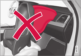
SAFETY
}}
65
impact. The same can also happen if the infant or
child rides unrestrained on the seat. Other occu-
pants should also be properly restrained to help
reduce the chance of injuring or increasing the
injury of a child.
All states and provinces have legislation govern-
ing how and where children should be carried in
a vehicle. Find out the regulations existing in your
state or province. Recent accident statistics have
shown that children are safer in rear seating
positions than front seating positions when prop-
erly restrained. A child restraint system can help
protect a child in a vehicle. Here's what to look
for when selecting a child restraint system:
It should have a label certifying that it meets
applicable Federal Motor Vehicle Safety Stand-
ards (FMVSS 213) – or in Canada, CMVSS 213.
Make sure the child restraint system is approved
for the child's height, weight and development –
the label required by the standard or regulation,
or instructions for infant restraints, typically pro-
vide this information.
In using any child restraint system, we urge you
to carefully look over the instructions that are
provided with the restraint. Be sure you under-
stand them and can use the device properly and
safely in this vehicle. A misused child restraint
system can result in increased injuries for both
the infant or child and other occupants in the
vehicle.
When a child has outgrown the child safety seat,
you should use the rear seat with the standard
seat belt fastened. The best way to help protect
the child here is to place the child on a cushion
so that the seat belt is properly located on the
hips. Legislation in your state or province may
mandate the use of a child seat or cushion in
combination with the seat belt, depending on the
child's age and/or size. Please check local regu-
lations.
A specially designed and tested booster cushion
and backrest can be obtained from your Volvo
retailer.
USA: for children weighing 33 – 80 lbs. (15 –
36 kg) and 38 – 54 inches (97 – 137 cm) in
height
Canada: for children weighing 40 – 80 lbs. (18 –
36 kg) and 40 – 54 inches (102 – 137 cm) in
height
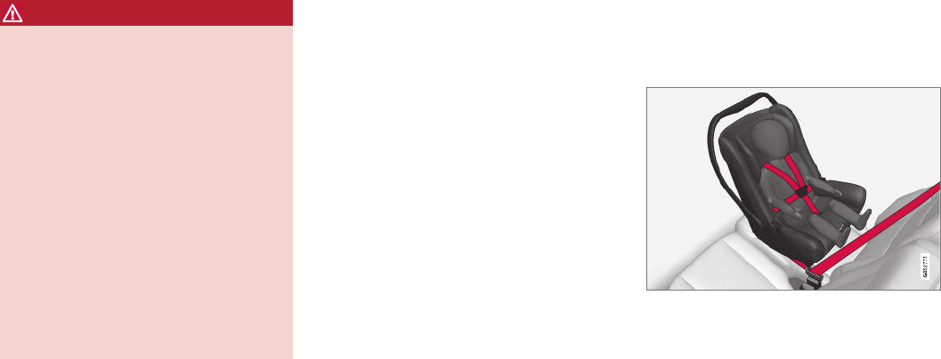
||
SAFETY
* Option/accessory, for more information, see Introduction.
66
WARNING
•Do not use child safety seats or child
booster cushions/backrests in the front
passenger's seat. We also recommend
that children under 4 feet 7 inches
(140 cm) in height who have outgrown
these devices sit in the rear seat with the
seat belt fastened.
•Sedan models: Keep vehicle doors and
trunk locked and keep remote controls
out of a child’s reach. Unsupervised chil-
dren could lock themselves in an open
trunk and risk injury. Children should be
taught not to play in vehicles.
•On hot days, the temperature in the vehi-
cle interior can rise very quickly. Exposure
to these high temperatures for even a
short period of time can cause heat-rela-
ted injury or death. Small children are par-
ticularly at risk.
Child seats should always be registered.
Volvo's recommendations
Why does Volvo believe that no child should sit in
the front seat of a car? It's quite simple really. A
front airbag is a very powerful device designed,
by law, to help protect an adult.
Because of the size of the airbag and its speed
of inflation, a child should never be placed in the
front seat, even if he or she is properly belted or
strapped into a child safety seat. Volvo has been
an innovator in safety for over seventy-five years,
and we'll continue to do our part. But we need
your help. Please remember to put your children
in the back seat, and buckle them up.
Volvo has some very specific
recommendations
•Always wear your seat belt.
•Airbags are a SUPPLEMENTAL safety
device which, when used with a three-point
seat belt can help reduce serious injuries
during certain types of accidents. Volvo rec-
ommends that you do not disconnect the air-
bag system in your vehicle.
•Volvo strongly recommends that everyone in
the vehicle be properly restrained.
•Volvo recommends that ALL occupants
(adults and children) shorter than 4 feet
7 inches (140 cm) be seated in the back
seat of any vehicle with a front passenger
side airbag.
•Drive safely!
Related information
•Integrated booster cushion* (p. 77)
•Booster cushions (p. 73)
•Convertible seats (p. 70)
•Infant seats (p. 68)
•ISOFIX/LATCH lower anchors (p. 74)
•Top tether anchors (p. 76)
Child restraints
Suitable child restraints should always be used
when children travel in the vehicle.
Child restraint systems
Infant seat
There are three main types of child restraint sys-
tems: infant seats, convertible seats and booster
cushions. They are classified according to the
child's age and size.
The child restraint should be secured using a
three-point seat belt, ISOFIX/LATCH anchors or
top tether anchors.
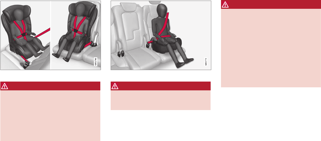
SAFETY
}}
67
Convertible seat
WARNING
A child seat should never be used in the front
passenger seat of any vehicle with a front
passenger airbag – not even if the "Passen-
ger airbag off" symbol near the rear-view mir-
ror is illuminated (on vehicles equipped with
Occupant Weight Sensor). If the severity of an
accident were to cause the airbag to inflate,
this could lead to serious injury or death to a
child seated in this position.
Booster cushion
WARNING
Always refer to the child restraint manufactur-
er's instructions for detailed information on
securing the restraint.
WARNING
•When not in use, keep the child restraint
system secured or remove it from the
passenger compartment to help prevent it
from injuring passengers in the event of a
sudden stop or collision.
•A small child's head represents a consid-
erable part of its total weight and its neck
is still very weak. Volvo recommends that
children up to age 4 travel, properly
restrained, facing rearward. In addition,
Volvo recommends that children should
ride rearward facing, properly restrained,
as long as possible.
Automatic Locking Retractor/
Emergency Locking Retractor (ALR/
ELR)
To make child seat installation easier, each seat
belt (except for the driver's belt) is equipped with
a locking mechanism to help keep the seat belt
taut.
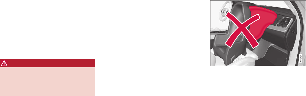
||
SAFETY
68
When attaching the seat belt to a child seat:
1. Attach the seat belt to the child seat accord-
ing to the child seat manufacturer's instruc-
tions.
2. Pull the seat belt out as far as possible.
3. Insert the seat belt latch plate into the buckle
(lock) in the usual way.
4. Release the seat belt and pull it taut around
the child seat.
A sound from the seat belt retractor will be audi-
ble at this time and is normal. The belt will now
be locked in place. This function is automatically
disabled when the seat belt is unlocked and the
belt is fully retracted.
WARNING
Do not use child safety seats or child booster
cushions/backrests in the front passenger's
seat. We also recommend that children who
have outgrown these devices sit in the rear
seat with the seat belt properly fastened.
Child restraint registration and recalls
Child restraints could be recalled for safety rea-
sons. You must register your child restraint to be
reached in a recall. To stay informed about child
safety seat recalls, be sure to fill out and return
the registration card that comes with new child
restraints.
Child restraint recall information is readily availa-
ble in both the U.S. and Canada. For recall infor-
mation in the U.S., call the U.S. Government's
Auto Safety Hotline at 1-800-424-9393 or go to
http://www-odi.nhtsa.dot.gov/cars/problems/
recalls/register/childseat/index.cfm. In Canada,
visit Transport Canada's Child Safety website at
http://www.tc.gc.ca/roadsafety/childsafety/
menu.htm.
Infant seats
Suitable child restraints should always be used
when children (depending on their age/size) are
seated in the vehicle.
Securing an infant seat with a seat belt
Do not place the infant seat in the front passenger's
seat
1. Place the infant seat in the rear seat of the
vehicle.
2. Attach the seat belt to the infant seat
according to the manufacturer's instructions.
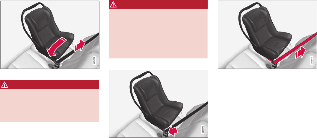
SAFETY
}}
69
Positioning the seat belt through the infant seat
WARNING
•An infant seat must be in the rear-facing
position only.
•The infant seat should not be positioned
behind the driver's seat unless there is
adequate space for safe installation.
WARNING
A child seat should never be used in the front
passenger seat of any vehicle with a front
passenger airbag – not even if the "Passen-
ger airbag off" symbol near the rear-view mir-
ror is illuminated (on vehicles equipped with
Occupant Weight Sensor). If the severity of an
accident were to cause the airbag to inflate,
this could lead to serious injury or death to a
child seated in this position.
3.
Fasten the seat belt
Fasten the seat belt by inserting the latch
plate into the buckle (lock) until a distinct
click is audible.
Pull out the shoulder section of the seat belt
4. Pull the shoulder section of the seat belt out
as far as possible to activate the belt's auto-
matic locking function.
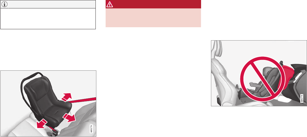
||
SAFETY
70
NOTE
The locking retractor will automatically
release when the seat belt is unbuckled and
allowed to retract fully.
5. Press the infant seat firmly in place, let the
seat belt retract and pull it taut. A sound from
the seat belt retractor's automatic locking
function will be audible at this time and is
normal. The seat belt should now be locked
in place.
Ensure that the seat is securely in place
6. Push and pull the infant seat along the seat
belt path to ensure that it is held securely in
place by the seat belt.
WARNING
It should not be possible to move the child
restraint (child seat) more than 1 in. (2.5 cm)
in any direction along the seat belt path.
The infant seat can be removed by unbuckling
the seat belt and letting it retract completely.
Related information
•ISOFIX/LATCH lower anchors (p. 74)
•Top tether anchors (p. 76)
•Convertible seats (p. 70)
•Buckling and unbuckling seat belts (p. 61)
•Child safety (p. 64)
Convertible seats
Suitable child restraints should always be used
when children (depending on their age/size) are
seated in the vehicle.
Securing a convertible seat with a seat
belt
Do not place the convertible seat in the front passeng-
er's seat
Convertible seats can be used in either a forward
or rearward-facing position, depending on the
age and size of the child.
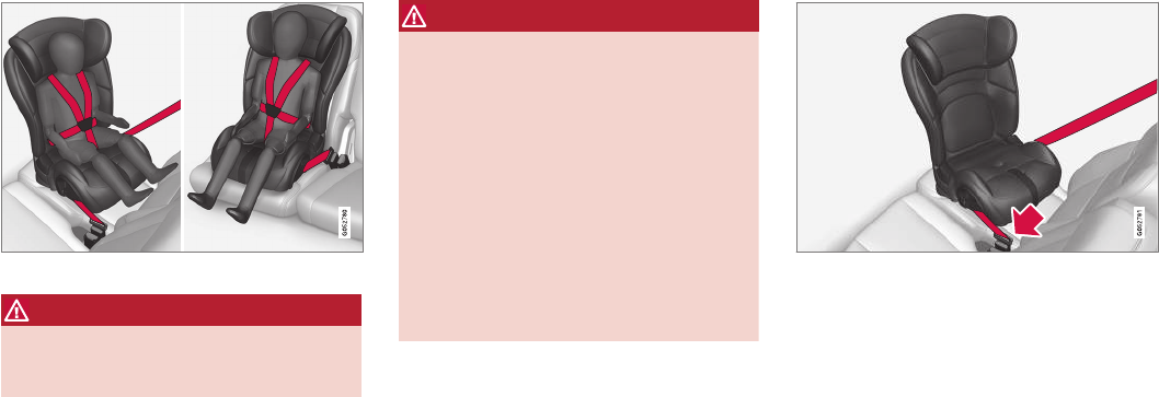
SAFETY
}}
71
Route the seat belt through the convertible seat
WARNING
Always use a convertible seat that is suitable
for the child's age and size. See the converti-
ble seat manufacturer's recommendations.
1. Place the convertible seat in the rear seat of
the vehicle.
WARNING
•A small child's head represents a consider-
able part of its total weight and its neck is
still very weak. Volvo recommends that
children up to age 4 travel, properly
restrained, facing rearward. In addition,
Volvo recommends that children should
ride rearward facing, properly restrained, as
long as possible.
•Convertible child seats should be installed
in the rear seat only.
•A rear-facing convertible seat should not
be positioned behind the driver's seat
unless there is adequate space for safe
installation.
2. Attach the seat belt to the convertible seat
according to the manufacturer's instructions.
Fasten the seat belt
3. Fasten the seat belt by inserting the latch
plate into the buckle (lock) until a distinct
click is audible.
4. Pull the shoulder section of the seat belt out
as far as possible to activate the belt's auto-
matic locking function.
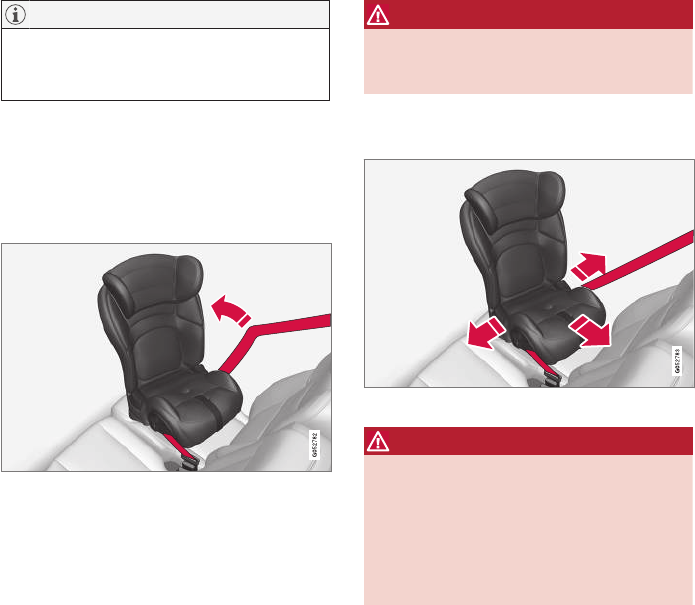
||
SAFETY
72
NOTE
The locking retractor will automatically
release when the seat belt is unbuckled and
allowed to retract fully.
5. Press the convertible seat firmly in place, let
the seat belt retract and pull it taut. A sound
from the seat belt retractor's automatic lock-
ing function will be audible at this time and is
normal. The seat belt should now be locked
in place.
Pull out the shoulder section of the seat belt
6. Push and pull the convertible seat along the
seat belt path to ensure that it is held
securely in place by the seat belt.
WARNING
It should not be possible to move the child
restraint (child seat) more than 1 in. (2.5 cm)
in any direction along the seat belt path.
The convertible seat can be removed by unbuck-
ling the seat belt and letting it retract completely.
Ensure that the seat is securely in place
WARNING
A child seat should never be used in the front
passenger seat of any vehicle with a front
passenger airbag – not even if the "Passen-
ger airbag off" symbol near the rear-view mir-
ror is illuminated. If the severity of an accident
were to cause the airbag to inflate, this could
lead to serious injury or death to a child
seated in this position.
Related information
•ISOFIX/LATCH lower anchors (p. 74)
•Top tether anchors (p. 76)
•Booster cushions (p. 73)
•Buckling and unbuckling seat belts (p. 61)
•Child safety (p. 64)
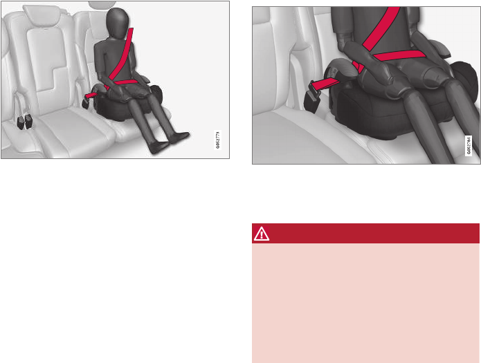
SAFETY
* Option/accessory, for more information, see Introduction. 73
Booster cushions
Securing a booster cushion
Position the child correctly on the booster cushion
Booster cushions are recommended for children
who have outgrown convertible seats.
1. Place the booster cushion in the rear seat of
the vehicle.
2. With the child properly seated on the booster
cushion, attach the seat belt to or around the
cushion according to the manufacturer's
instructions.
3. Fasten the seat belt by inserting the latch
plate into the buckle (lock) until a distinct
click is audible.
Positioning the seat belt
4. Ensure that the seat belt is pulled taut and
fits snugly around the child.
WARNING
•The hip section of the three-point seat
belt must fit snugly across the child's
hips, not across the stomach.
•The shoulder section of the three-point
seat belt should be positioned across the
chest and shoulder.
•The shoulder belt must never be placed
behind the child's back or under the arm.
Related information
•ISOFIX/LATCH lower anchors (p. 74)
•Top tether anchors (p. 76)
•Child safety (p. 64)
•Buckling and unbuckling seat belts (p. 61)
•Integrated booster cushion* (p. 77)
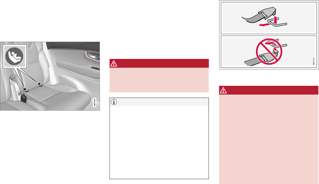
SAFETY
74
ISOFIX/LATCH lower anchors
Lower anchors for ISOFIX/LATCH-equipped
child seats are located in the rear, outboard
seats, hidden below the backrest cushions.
Using the ISOFIX/LATCH lower child
seat anchors
Location of the ISOFIX/LATCH anchors
Symbols on the seat back upholstery mark the
ISOFIX/LATCH anchor positions as shown. To
access the anchors, kneel on the seat cushion
and locate the anchors by feel. Always follow your
child seat manufacturer's installation instructions,
and use both ISOFIX/LATCH lower anchors and
top tethers whenever possible.
To access the anchors
1. Put the child restraint in position.
2. Kneel on the child restraint to press down
the seat cushion and locate the anchors by
feel.
3. Fasten the attachment on the child
restraint's lower straps to the ISOFIX/
LATCH/LATCH lower anchors.
4. Firmly tension the lower child seat straps
according to the manufacturer's instructions.
WARNING
Volvo's ISOFIX/LATCH anchors conform to
FMVSS/CMVSS standards. Always refer to
the child restraint system's manual for weight
and size ratings.
NOTE
•The rear seat's center position is not
equipped with ISOFIX/LATCH lower
anchors. When installing a child restraint
in this position, attach the restraint's top
tether strap (if it is so equipped) to the
top tether anchorage point and secure
the restraint with the vehicle's center seat
belt.
•Always follow your child seat manufactur-
er's installation instructions, and use both
ISOFIX/LATCH lower anchors and top
tethers whenever possible.
Fasten the attachment correctly to the ISOFIX/LATCH
lower anchors
WARNING
•Be sure to fasten the attachment cor-
rectly to the anchor (see the illustration).
If the attachment is not correctly fas-
tened, the child restraint may not be
properly secured in the event of a colli-
sion.
•The ISOFIX/LATCH lower child restraint
anchors are only intended for use with
child seats positioned in the outboard
seating positions. These anchors are not
certified for use with any child restraint
that is positioned in the center seating
position. When securing a child restraint
in the center seating position, use only
the vehicle's center seat belt.
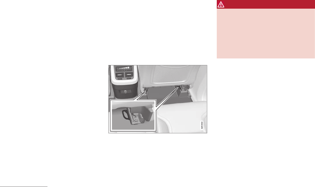
SAFETY
75
Related information
•Top tether anchors (p. 76)
Lower child seat attachment points1
The vehicle is equipped with lower attachment
points for child seats in the second row of seats.
The lower attachment points are intended for use
with rear-facing child restraints.
Always follow the child restraint manufacturer's
installation instructions when attaching a child
restraint to these attachment points.
Location
Attachment points in the second row of seats
The attachment points in the second row of seats
are in the rear section of the front seat's floor
rails.
WARNING
A child seat should never be used in the front
passenger seat of any vehicle with a front
passenger airbag – not even if the "Passen-
ger airbag off" symbol near the rear-view mir-
ror is illuminated (on vehicles equipped with
Occupant Weight Sensor). If the severity of an
accident were to cause the airbag to inflate,
this could lead to serious injury or death to a
child seated in this position.
Related information
•Child restraints (p. 66)
•ISOFIX/LATCH lower anchors (p. 74)
•Occupant weight sensor (p. 80)
1Not available in all markets
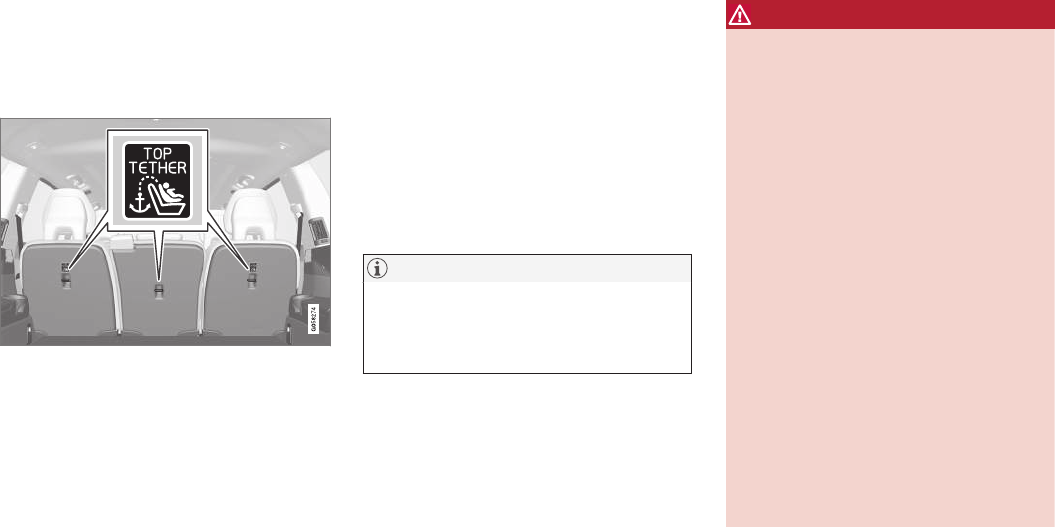
SAFETY
76
Top tether anchors
Your Volvo is equipped with child restraint top
tether anchorages in the rear seat. They are
located on the rear side of the backrests.
Child restraint anchorages
Top tether anchors and symbols on the rear side of the
second row backrests. There is no symbol for the center
anchor position.
Securing a child seat
1. Place the child restraint on the rear seat.
2. Route the top tether strap under the head
restraint and attach it to the anchor.
3. Attach lower tether straps to the lower ISO-
FIX/LATCH anchors. If the child restraint is
not equipped with lower tether straps, or the
restraint is used in the center seating posi-
tion, follow instructions for securing a child
restraint using the Automatic Locking
Retractor seat belt.
–Firmly tension all straps.
Refer also to the child seat manufacturer's
instructions for information on securing the child
seat.
NOTE
On models equipped with the optional cargo
area cover, this cover should be removed
before a child seat is attached to the child
restraint anchors.
WARNING
•Always refer to the recommendations
made by the child restraint manufacturer.
•Volvo recommends that the top tether
anchors be used when installing a for-
ward-facing child restraint.
•Never route a top tether strap over the
top of the head restraint. The strap
should be routed beneath the head
restraint.
•Child restraint anchorages are designed
to withstand only those loads imposed by
correctly fitted child restraints. Under no
circumstances are they to be used for
adult seat belts or harnesses. The ancho-
rages are not able to withstand excessive
forces on them in the event of collision if
full harness seat belts or adult seat belts
are installed to them. An adult who uses a
belt anchored in a child restraint anchor-
age runs a great risk of suffering severe
injuries should a collision occur.
•Do not install rear speakers that require
the removal of the top tether anchors or
interfere with the proper use of the top
tether strap.
Related information
•Child safety (p. 64)
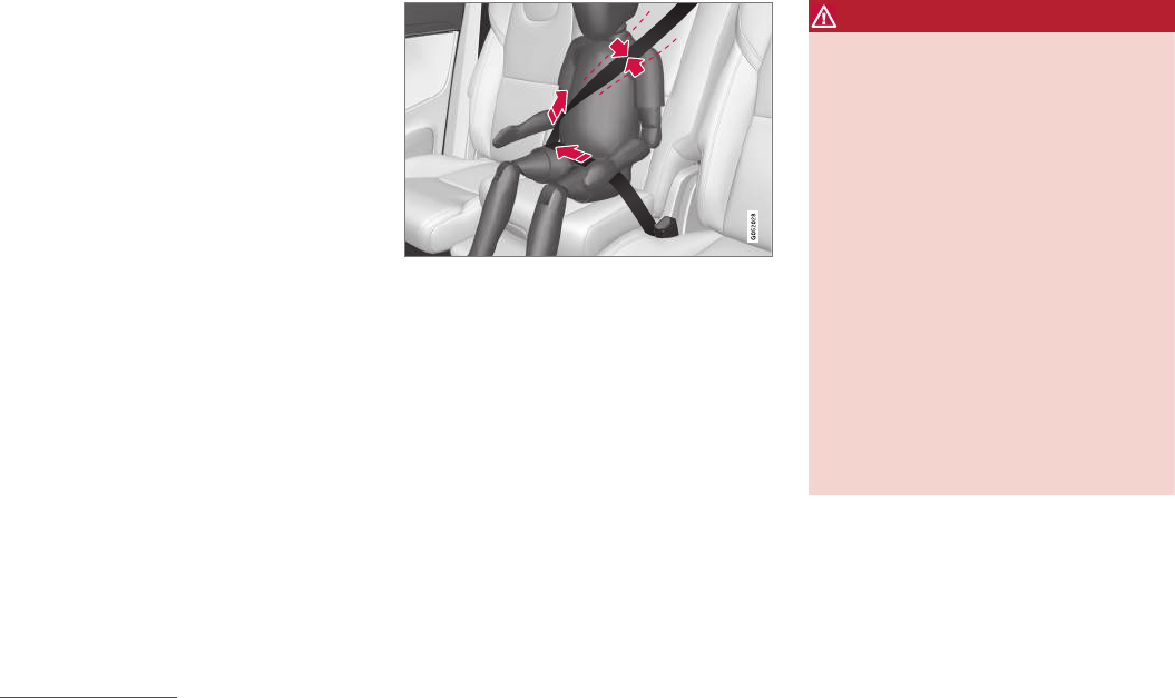
SAFETY
}}
* Option/accessory, for more information, see Introduction. 77
Integrated booster cushion*
Volvo's optional integrated booster cushion is
located in the rear seat's center position and is
designed to raise the child higher so that the
shoulder strap crosses over the child's collar-
bone, not over the neck.
Integrated booster cushion2
This booster cushion has been specially
designed to help safeguard children in the rear
seat. It should be stowed (folded down into the
seat cushion) when not in use. When using an
integrated booster cushion, the child must be
secured with the vehicle's three-point seat belt.
Use this booster cushion only with a
child whose weight is between 33–
80 lbs (15–36 kg) and whose height is
at least 37 in. (95 cm).
In Canada, Transport Canada's weight
recommendation is 40 – 80 lbs (18 –
36 kg).
If using a booster cushion does not result in
proper positioning of the shoulder strap, then the
child should be placed in a properly secured child
restraint. The shoulder belt must never be placed
behind the child's back or under the arm.
Correct seating position: child's head is below the head
restraint and the shoulder belt is across the collarbone
WARNING
DEATH or SERIOUS INJURY can
occur
Follow all instructions on the booster
cushion and in the vehicle's owner's
manual.
MAKE SURE THE BOOSTER
CUSHION IS SECURELY LOCKED
BEFORE THE CHILD IS SEATED.
•Use this booster cushion only with chil-
dren whose height and weight are within
the permitted limits.
•In the event of a collision while the inte-
grated booster cushion was occupied, the
entire booster cushion and seat belt must
be replaced. The booster cushion should
also be replaced if it is badly worn or
damaged in any way. This work should be
performed by a trained and qualified
Volvo service technician only.
Before driving, check that:
•The integrated booster cushion has been
correctly raised and locked in position.
2Canada only: This cushion may be referred to as a built-in booster cushion.
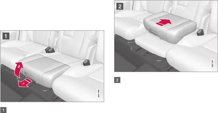
||
SAFETY
* Option/accessory, for more information, see Introduction.
78
•That the seat belt is properly positioned and
is taut.
•The shoulder section of the seat belt is
across the child's collarbone, not over the
neck.
•The lap section of the seat belt is across the
child's hips and not the abdomen.
Related information
•Seat belts (p. 60)
•Child safety (p. 64)
•Raising the integrated booster cushion*
(p. 78)
•Stowing the integrated booster cushion*
(p. 79)
Raising the integrated booster
cushion*
The integrated booster cushion must be cor-
rectly raised before use.
Pull the handle forward and upward to
release the booster cushion.
Press the booster cushion rearward to lock it
in position.
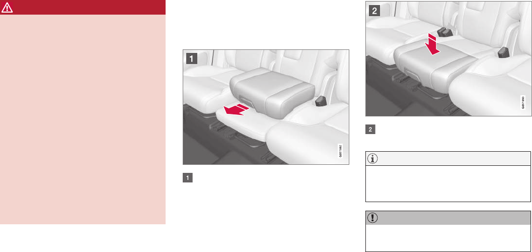
SAFETY
}}
* Option/accessory, for more information, see Introduction. 79
WARNING
DEATH or SERIOUS INJURY can
occur
Follow all instructions on the booster
cushion and in the vehicle's owner's
manual.
MAKE SURE THE BOOSTER
CUSHION IS SECURELY LOCKED
BEFORE THE CHILD IS SEATED.
•Use this booster cushion only with chil-
dren whose height and weight are within
the permitted limits.
•In the event of a collision while the inte-
grated booster cushion was occupied, the
entire booster cushion and seat belt must
be replaced. The booster cushion should
also be replaced if it is badly worn or
damaged in any way. This work should be
performed by a trained and qualified
Volvo service technician only.
Related information
•Integrated booster cushion* (p. 77)
•Stowing the integrated booster cushion*
(p. 79)
Stowing the integrated booster
cushion*
The integrated booster cushion should be
stowed (folded down) when not in use.
Pull the handle forward to release the
booster cushion.
Press down on the center of the booster
cushion to return it to the stowed position.
NOTE
The booster cushion must be in the stowed
position before the rear seat backrests are
folded down.
CAUTION
Be sure there are no loose objects under the
booster cushion before it is stowed.
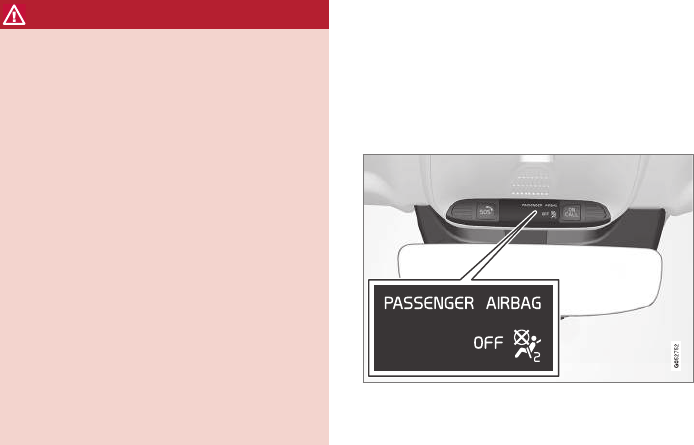
||
SAFETY
* Option/accessory, for more information, see Introduction.
80
WARNING
DEATH or SERIOUS INJURY can
occur
Follow all instructions on the booster
cushion and in the vehicle's owner's
manual.
MAKE SURE THE BOOSTER
CUSHION IS SECURELY LOCKED
BEFORE THE CHILD IS SEATED.
•Use this booster cushion only with chil-
dren whose height and weight are within
the permitted limits.
•In the event of a collision while the inte-
grated booster cushion was occupied, the
entire booster cushion and seat belt must
be replaced. The booster cushion should
also be replaced if it is badly worn or
damaged in any way. This work should be
performed by a trained and qualified
Volvo service technician only.
Related information
•Integrated booster cushion* (p. 77)
•Raising the integrated booster cushion*
(p. 78)
Occupant weight sensor
The Occupant Weight Sensor (OWS) is
designed to meet the regulatory requirements of
Federal Motor Vehicle Safety Standard (FMVSS)
208 and is designed to disable (will not inflate)
the passenger's side front airbag under certain
conditions.
Occupant Weight Sensor (OWS) indicator light
Disabling the passenger's side front
airbag
Volvo recommends that ALL occupants (adults
and children) shorter than 4 feet 7 inches
(140 cm) be seated in the back seat of any vehi-
cle with a front passenger side airbag and be
properly restrained for their size and weight.
The OWS works with sensors that are part of the
front passenger's seat and seat belt. The sensors
are designed to detect the presence of a properly
seated occupant and determine if the passeng-
er's side front airbag should be enabled (may
inflate) or disabled (will not inflate).
The OWS will disable (will not inflate) the pas-
senger's side front airbag when:
•the front passenger's seat is unoccupied, or
has small/medium objects in the front seat,
•the system determines that an infant is pres-
ent in a rear-facing infant seat that is instal-
led according to the manufacturer's instruc-
tions,
•the system determines that a small child is
present in a forward-facing child restraint
that is installed according to the manufactur-
er's instructions,
•the system determines that a small child is
present in a booster seat,
•a front passenger takes his/her weight off of
the seat for a period of time,
•a child or a small person occupies the front
passenger's seat.
The OWS uses a PASSENGER AIRBAG OFF
indicator lamp which will illuminate and stay on to
remind you that the passenger's side front airbag
is disabled. The PASSENGER AIRBAG OFF indi-
cator lamp is located in the overhead console,
near the base of the rearview mirror.
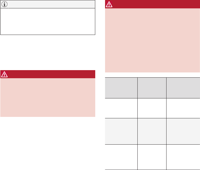
SAFETY
}}
81
NOTE
When the ignition is switched on, the OWS
indicator light will illuminate for several sec-
onds while the system performs a self-diag-
nostic test.
However, if a fault is detected in the system:
•The OWS indicator light will stay on
•The SRS warning light will come on and stay
on and a text message will be displayed.
WARNING
If a fault in the system is detected and indi-
cated as described, be aware that the pas-
senger's side front airbag will not deploy in
the event of a collision. In this case, the SRS
system and Occupant Weight Sensor should
be inspected by a trained and qualified Volvo
service technician as soon as possible.
WARNING
•Never try to open, remove, or repair any
components in the OWS system. This
could result in system malfunction. Main-
tenance or repairs should only be carried
out by an a trained and qualified Volvo
service technician.
•The front passenger's seat should not be
modified in any way. This could reduce
pressure on the seat cushion, which
might interfere with the OWS system's
function.
Passenger's
seat occu-
pancy status
OWS indi-
cator light
status
Passenger's
side front air-
bag status
Seat unoccu-
pied
OWS indi-
cator light
lights up.
Passenger's
side front air-
bag disabled
Seat occu-
pied by low
weight occu-
pant/objectA
OWS indi-
cator light
lights up
Passenger's
side front air-
bag disabled
Seat occu-
pied by heavy
occupant/
object
OWS indi-
cator light is
not lit
Passenger's
side front air-
bag enabled
AVolvo recommends that children always be properly restrained
in appropriate child restraints in the rear seats. Do not assume
that the passenger's side front airbag is disabled unless the
PASSENGER AIRBAG OFF indicator lamp is lit. Make sure the
child restraint is properly installed. If there is any doubt as to the
status of the passenger's side front airbag, move the child
restraint to the rear seat.
The OWS is designed to enable (may inflate) the
passenger's side front airbag in the event of a
collision anytime the system senses that a per-
son of adult size is sitting properly in the front
passenger's seat. The PASSENGER AIRBAG
OFF indicator lamp will be off and remain off.
If a person of adult size is sitting in the front pas-
senger's seat, but the PASSENGER AIRBAG
OFF indicator lamp is on, it is possible that the
person isn't sitting properly in the seat. If this
happens:
•Turn the vehicle off and ask the person to
place the seatback in an upright position.
•Have the person sit upright in the seat, cen-
tered on the seat cushion, with the person's
legs comfortably extended.
•Restart the vehicle and have the person
remain in this position for about two minutes.
This will allow the system to detect that per-
son and enable the passenger's frontal air-
bag.
•If the PASSENGER AIRBAG OFF indicator
lamp remains on even after this, the person
should be advised to ride in the rear seat.
This condition reflects limitations of the OWS
classification capability. It does not indicate OWS
malfunction.

||
SAFETY
82
Modifications
If you are considering modifying your vehicle in
any way to accommodate a disability, for example
by altering or adapting the driver's or front pas-
senger's seat(s) and/or airbag systems, please
contact Volvo at:
In the USA
Volvo Cars of North America, LLC
Customer Care Center
1 Volvo Drive
P.O. Box 914
Rockleigh, New Jersey 07647
1-800-458-1552
In Canada
Volvo Cars of Canada Corp.
National Customer Service
9130 Leslie Street, Suite 101
Richmond Hill, Ontario L4B 0B9
1-800-663-8255
WARNING
•No objects that add to the total weight on
the seat should be placed on the front
passenger's seat. If a child is seated in
the front passenger's seat with any addi-
tional weight, this extra weight could
cause the OWS system to enable the air-
bag, which might cause it to deploy in the
event of a collision, thereby injuring the
child.
•The seat belt should never be wrapped
around an object on the front passeng-
er's seat. This could interfere with the
OWS system's function.
•The front passenger's seat belt should
never be used in a way that exerts more
pressure on the passenger than normal.
This could increase the pressure exerted
on the weight sensor by a child, and
could result in the airbag being enabled,
which might cause it to deploy in the
event of a collision, thereby injuring the
child.
WARNING
•Keep the following points in mind with
respect to the OWS system. Failure to
follow these instructions could adversely
affect the system's function and result in
serious injury to the occupant of the front
passenger's seat:
•The full weight of the front seat passen-
ger should always be on the seat cushion.
The passenger should never lift him/
herself off the seat cushion using the
armrest in the door or the center console,
by pressing the feet on the floor, by sit-
ting on the edge of the seat cushion, or
by pressing against the backrest in a way
that reduces pressure on the seat cush-
ion. This could cause OWS to disable the
front, passenger's side airbag.
WARNING
•Do not place any type of object on the
front passenger's seat in such a way that
jamming, pressing, or squeezing occurs
between the object and the front seat,
other than as a direct result of the correct
use of the Automatic Locking Retractor/
Emergency Locking Retractor (ALR/ELR)
seat belt.
•No objects should be placed under the
front passenger's seat. This could inter-
fere with the OWS system's function.

SAFETY
83
Related information
•Airbag system (p. 84)
Safety mode
As a safety precaution after a collision, the func-
tionality of some of the vehicle's systems may be
reduced.
If the vehicle has been involved in a collision, the
text Safety mode may appear in the information
display.
NOTE
This text can only be shown if the display is
undamaged and the vehicle's electrical sys-
tem is intact.
Safety mode is a feature that is triggered if one
or more of the safety systems such as the front/
side airbags inflatable curtain, etc., or one or
more of the seat belt pretensioners has deployed.
The collision may have damaged an important
function in the vehicle, such as the fuel lines,
sensors for one of the safety systems, the brake
system, etc.
WARNING
•Never attempt to repair the vehicle your-
self or to reset the electrical system after
the vehicle has displayed Safety mode.
This could result in injury or improper sys-
tem function.
•Restoring the vehicle to normal operating
status should only be done by a trained
and qualified Volvo service technician.
•After Safety mode has been displayed, if
you detect the odor of fuel vapor, or see
any signs of fuel leakage, do not attempt
to start the vehicle. Leave the vehicle
immediately.
Related information
•Starting or moving a vehicle in safety mode
(p. 84)
•General safety information (p. 56)

SAFETY
84
Starting or moving a vehicle in
safety mode
If Safety mode has been set, it may be possible
to start and move the vehicle, for example, if it is
blocking traffic.
Starting the vehicle in safety mode
1. Check the vehicle for damage, particularly for
fuel leakage or the smell of gasoline fumes.
If the damage to the vehicle is minor and
there is no fuel leakage/fumes, you may
attempt to start the engine and move the
vehicle.
WARNING
If you smell gasoline fumes or detect fuel
leakage while Safety mode See Owner's
manual is displayed in the instrument panel,
do not attempt to start the vehicle. Leave
the vehicle immediately.
2. Turn the start knob to STOP and release it.
3. Try to start the vehicle.
>Vehicle start System check, wait will
be displayed in the instrument panel while
the vehicle's electrical system attempts to
reset to normal mode.
WARNING
If the message Safety mode See Owner's
manual is still displayed, the vehicle should
not be driven and must be towed. Concealed
faults may make the vehicle difficult to control.
Moving the vehicle after safety mode
has been set
If the message Normal mode The vehicle is
now in normal mode is displayed, the vehicle
may be moved carefully from its present position
if, for example, it is blocking traffic.
It should, however, not be moved farther than
is absolutely necessary.
WARNING
After Safety mode has been set, the vehicle
should not be driven or towed (pulled on the
ground by another vehicle). It must be trans-
ported on a flatbed tow truck to a trained and
qualified Volvo service technician for inspec-
tion/repairs.
Related information
•Safety mode (p. 83)
•Towing recommendations (p. 349)
Airbag system
As an enhancement to the three-point seat belts,
your vehicle is equipped with an airbag system.
WARNING
•If the airbag warning light stays on after
the engine has started or if it illuminates
while you are driving, have the vehicle
inspected by a trained and qualified Volvo
service technician as soon as possible.
•Never try to repair any component or part
of the airbag systems yourself. Any inter-
ference in the system could cause mal-
function and serious injury. All work on
these systems should be performed by a
trained and qualified Volvo service techni-
cian.
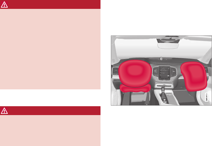
SAFETY
}}
85
WARNING
If your vehicle has become flood-damaged in
any way (e.g., soaked carpeting/standing
water on the floor of the vehicle), do not
attempt to start the vehicle. This may cause
airbag deployment which could result in seri-
ous injury. Have the vehicle towed to a trained
and qualified Volvo service technician for
repairs.
Before attempting to tow the vehicle:
1. Switch off the ignition for at least
10 minutes and disconnect the battery.
2. Follow the instructions for manually over-
riding the shiftlock system.
Deployed airbags
WARNING
If any of the airbags have deployed:
•Do not attempt to drive the vehicle. Have
it towed to a qualified repair facility.
•If necessary seek medical attentIon.
Driver/passenger side airbags
The front airbags supplement the three-point
seat belts. For these airbags to provide the pro-
tection intended, seat belts must be worn at all
times.
Driver's and passenger's side airbags
The front airbag system
The front airbag system includes gas generators
surrounded by the airbags, and deceleration sen-
sors that activate the gas generators, causing the
airbags to be inflated with nitrogen gas.
As the movement of the seats' occupants com-
presses the airbags, some of the gas is expelled
at a controlled rate to provide better cushioning.
Both seat belt pretensioners also deploy, mini-
mizing seat belt slack. The entire process, includ-
ing inflation and deflation of the airbags, takes
approximately one fifth of a second.
The location of the front airbags is indicated by
SRS AIRBAG embossed on the steering wheel
pad and above the glove compartment, and by
decals on both sun visors and on the front and
far right side of the dash.
The driver's side front airbag is folded and
located in the steering wheel hub.
The knee airbag is folded on the underside of
the dashboard on the driver's side. The text
AIRBAG is embossed on the panel.
The passenger's side front airbag is folded
behind a panel located above the glove compart-
ment.

||
SAFETY
86
WARNING
•The airbags in the vehicle are designed to
be a SUPPLEMENT to–not a replace-
ment for–the three-point seat belts. For
maximum protection, wear seat belts at all
times. Be aware that no system can pre-
vent all possible injuries that may occur in
an accident.
•Never drive with your hands on the steer-
ing wheel pad/airbag housing.
•The front airbags are designed to help
prevent serious injury. Deployment occurs
very quickly and with considerable force.
During normal deployment and depend-
ing on variables such as seating position,
one may experience abrasions, bruises,
swellings, or other injuries as a result
from deployment of one or both of the
airbags.
•When installing any accessory equipment,
make sure that the front airbag system is
not damaged. Any interference in the sys-
tem could cause malfunction.
Front airbag deployment
•The front airbags are designed to deploy dur-
ing certain frontal or front-angular collisions,
impacts, or decelerations, depending on the
crash severity, angle, speed and object
impacted. The airbags may also deploy in
certain non-frontal collisions where rapid
deceleration occurs.
•The airbag system sensors, which trigger the
front airbags, are designed to react to both
the impact of the collision and the inertial
forces generated by it, and to determine if
the intensity of the collision is sufficient for
the seat belt pretensioners and/or airbags to
be deployed.
However, not all frontal collisions activate the
front airbags.
•If the collision involves a nonrigid object (e.g.,
a snow drift or bush), or a rigid, fixed object
at a low speed, the front airbags will not nec-
essarily deploy.
•Front airbags do not normally deploy in a
side impact collision, in a collision from the
rear or in a rollover situation.
•The amount of damage to the bodywork
does not reliably indicate if the airbags
should have deployed or not.
NOTE
•Deployment of front airbags occurs only
one time during an accident. In a collision
where deployment occurs, the airbags
and seat belt pretensioners activate.
Some noise occurs and a small amount
of powder is released. The release of the
powder may appear as smoke-like matter.
This is a normal characteristic and does
not indicate fire.
•Volvo's front airbags use special sensors
that are integrated with the front seat
buckles. The point at which the airbag
deploys is determined by whether or not
the seat belt is being used, as well as the
severity of the collision.
•Collisions can occur where only one of
the airbags deploys. If the impact is less
severe, but severe enough to present a
clear injury risk, the airbags are triggered
at partial capacity. If the impact is more
severe, the airbags are triggered at full
capacity.
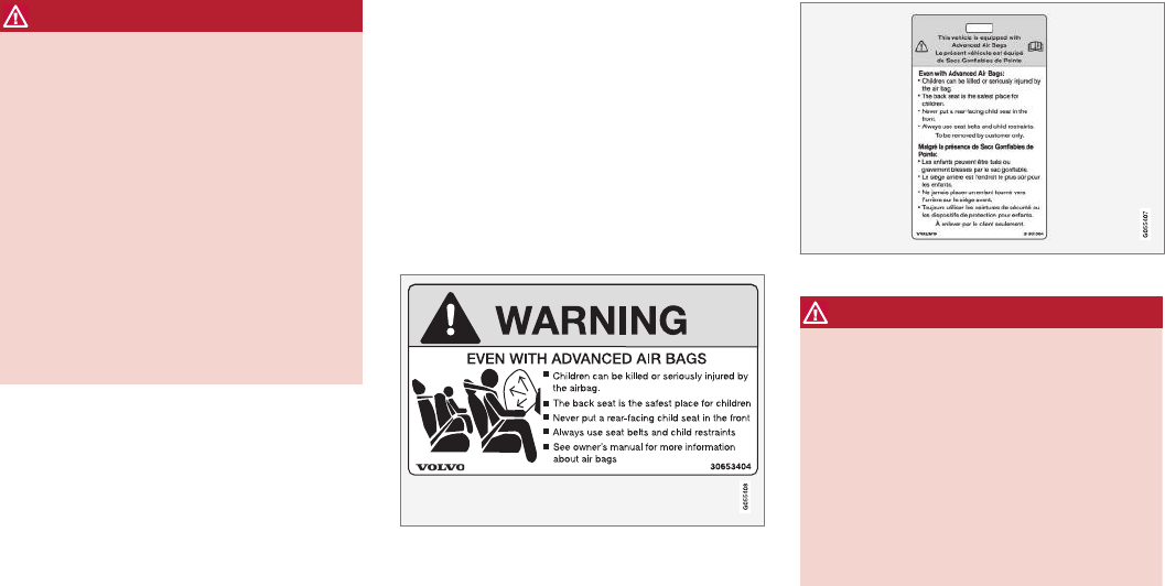
SAFETY
}}
87
WARNING
•Do not use child safety seats or child
booster cushions/backrests in the front
passenger's seat. We also recommend
that occupants under 4 feet 7 inches
(140 cm) in height who have outgrown
these devices sit in the rear seat with the
seat belt fastened. See also the Occu-
pant Weight Sensor information,.
•Never drive with the airbags deployed.
The fact that they hang out can impair the
steering of your vehicle. Other safety sys-
tems can also be damaged.
•The smoke and dust formed when the
airbags are deployed can cause skin and
eye irritation in the event of prolonged
exposure.
Should you have questions about any component
in the SRS system, please contact a trained and
qualified Volvo service technician or Volvo cus-
tomer support:
In the USA
Volvo Cars of North America, LLC
Customer Care Center
1 Volvo Drive
P.O. Box 914
Rockleigh, New Jersey 07647
1-800-458-1552
www.volvocars.com/us
In Canada
Volvo Cars of Canada Corp.
National Customer Service
9130 Leslie Street, Suite 101
Richmond Hill, Ontario L4B 0B9
1-800-663-8255
www.volvocars.com/ca
Airbag decals
Airbag decal on the outside of both sun visors
Passenger's side airbag decal
WARNING
•Children must never be allowed in the
front passenger's seat.
•Occupants in the front passenger's seat
must never sit on the edge of the seat, sit
leaning toward the instrument panel or
otherwise sit out of position.
•The occupant's back must be as upright
as comfort allows and be against the seat
back with the seat belt properly fastened.
•Feet must be on the floor, e.g., not on the
dash, seat or out of the window.
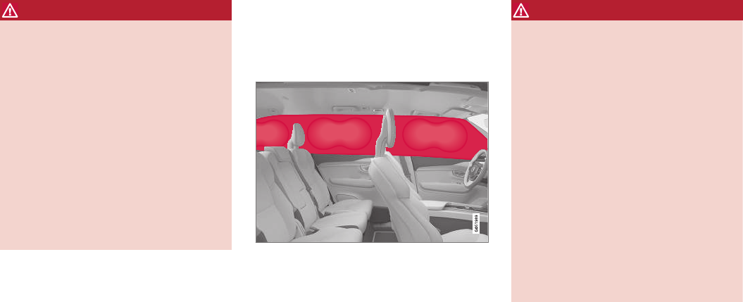
||
SAFETY
88
WARNING
•No objects or accessory equipment, e.g.
dashboard covers, may be placed on,
attached to, or installed near the air bag
hatch (the area above the glove compart-
ment) or the area affected by airbag
deployment.
•There should be no loose articles, such
as coffee cups on the floor, seat, or dash-
board area.
•Never try to open the airbag cover on the
steering wheel or the passenger's side
dashboard. This should only be done by a
trained and qualified Volvo service techni-
cian.
•Failure to follow these instructions can
result in injury to the vehicle occupants.
Related information
•Seat belts (p. 60)
•Occupant weight sensor (p. 80)
Inflatable curtains
The inflatable curtain is designed to help protect
the heads of the occupants of the front seats
and the occupant of the outboard rear seating
positions in certain side impact collisions.
This system consists of inflatable curtains located
along the sides of the roof liners, stretching from
the center of both front side windows to the rear
edge of the rear side door windows.
In certain side impacts, both the Inflatable Cur-
tain (IC) and the side Impact Airbag System
(SIPS airbag) will deploy. The IC and the SIPS
airbag deploy simultaneously.
WARNING
•Never try to open or repair any compo-
nents of the IC system. This should be
done only by a trained and qualified Volvo
service technician.
•Never hang heavy items from the ceiling
handles. This could impede deployment
of the Inflatable Curtain.
•The cargo area and rear seat should not
be loaded to a level higher than 4 in.
(10 cm) below the upper edge of the rear
side windows. Objects placed higher than
this level could impede the function of
the Inflatable Curtain.
•In order for the IC to provide its best pro-
tection, both front seat occupants and
both outboard rear seat occupants should
sit in an upright position with the seat belt
properly fastened; adults using the seat
belt and children using the proper child
restraint system.
Related information
•Airbag system (p. 84)
•Side impact airbags (p. 89)
•Child safety (p. 64)
•Seat belts (p. 60)
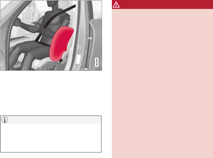
SAFETY
89
Side impact airbags
As an enhancement to the structural side impact
protection built into your vehicle, it is also equip-
ped with Side Impact Protection System (SIPS)
airbags.
The SIPS airbag system is designed to help
increase occupant protection in the event of cer-
tain side impact collisions. The SIPS airbags are
designed to deploy only during certain side-
impact collisions, depending on the crash
severity, angle, speed and point of impact.
NOTE
SIPS airbag deployment (one airbag) occurs
only on the side of the vehicle affected by the
impact. The airbags are not designed to
deploy in all side impact situations.
Components in the SIPS airbag system
This SIPS airbag system consists of a gas gener-
ator, the side airbag modules built into the out-
board sides of both front seat backrests, and
electronic sensors/wiring.
WARNING
•The SIPS airbag system is a supplement
to the structural Side Impact Protection
System and the three-point seat belt sys-
tem. It is not designed to deploy during
collisions from the front or rear of the
vehicle or in rollover situations.
•The use of seat covers on the front seats
may impede SIPS airbag deployment.
•No objects, accessory equipment or stick-
ers may be placed on, attached to or
installed near the SIPS airbag system or
in the area affected by SIPS airbag
deployment.
•Never try to open or repair any compo-
nents of the SIPS airbag system. This
should be done only by a trained and
qualified Volvo service technician.
•In order for the SIPS airbag to provide its
best protection, both front seat occupants
should sit in an upright position with the
seat belt properly fastened.
•Failure to follow these instructions can
result in injury to the occupants of the
vehicle in the event of an accident.
Related information
•Airbag system (p. 84)
•Seat belts (p. 60)


INSTRUMENTS AND CONTROLS
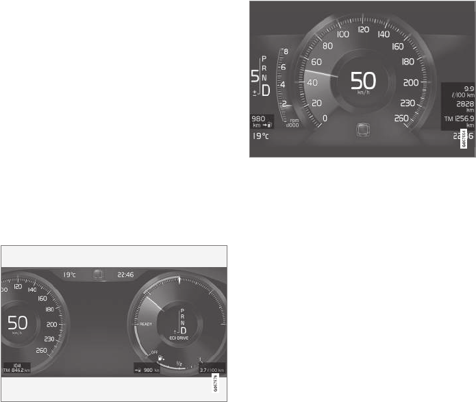
INSTRUMENTS AND CONTROLS
92
Trip computer
The trip computer registers and calculates infor-
mation such as distance driven, fuel consump-
tion and average speed. This information is dis-
played in the instrument panel.
To help promote fuel efficient driving, the trip
computer provides readings for current and aver-
age fuel consumption.
The trip computer includes the following
gauges:
•Trip odometers
•Odometer
•Current fuel consumption
•Distance to empty
•Tourist (alternative speedometer)
12" instrument panel
8" instrument panel
Trip odometer
There are two trip odometers: TM and TA. During
a drive, the trip odometer registers:
•Mileage
•Driving time
•Average speed
•Average fuel consumption
The values displayed are those since the last
time the trip odometer was reset.
Odometer
The odometer registers the vehicle's total mile-
age and cannot be reset.
Current fuel consumption
This gauge shows the current fuel consumption.
This reading is updated once a second.
Distance to empty
This function shows the approximate distance
that can be driven on the fuel remaining in the
tank.
The calculation is based on average fuel con-
sumption during the last 20 miles (30 km) of
driving and the amount of fuel remaining in the
tank.
When the gauge displays "----", there is very little
useable fuel remaining in the tank; refuel as soon
as possible.
The accuracy of this figure may vary if your driv-
ing style changes. An economical driving style will
generally increase this distance.
Tourist (alternative speedometer)
This is an alternative digital speedometer can be
used when driving in areas in which the speed
limit is listed in a different unit of measure. If the
speedometer is in mph, this gauge will show the
vehicle's speed in km/h and vice versa.
Related information
•Displaying trip computer information (p. 93)
•Displaying trip statistics (p. 94)
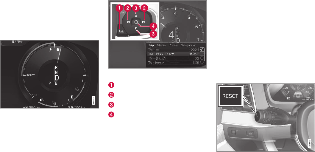
INSTRUMENTS AND CONTROLS
}}
93
Displaying trip computer
information
The trip computer registers and calculates infor-
mation such as distance driven, fuel consump-
tion and average speed. This information is dis-
played in the instrument panel.
Use the right-side steering wheel keypad to navigate in
the trip computer
Open/close the app menu
Left/right arrow keys
Up/down arrow keys
Confirm
1. Press (1) to open the app menu in the
instrument panel.
The app menu cannot be opened if there is
an a message in the instrument panel that
has not been confirmed. Press (4) to confirm.
2. The top four lines show readings from trip
odometer TM. The following four lines show
readings from trip odometer TA. Scroll up/
down in the list using (3).
3. Scroll to the selection buttons in the lines
below TA and select the trip odometer to be
displayed.
•Current fuel consumption
•Distance to empty
•Odometer
•Trip odometers TM, TA or none
•Tourist (alternative speedometer).
Select or deselect an alternative using the
center button (4). The change will be made
immediately.
Resetting a trip odometer
Reset trip odometer TM by pressing and holding
the RESET button the left-side steering wheel
lever. Trip odometer TA resets automatically if the
ignition is switched off for more than 4 hours.
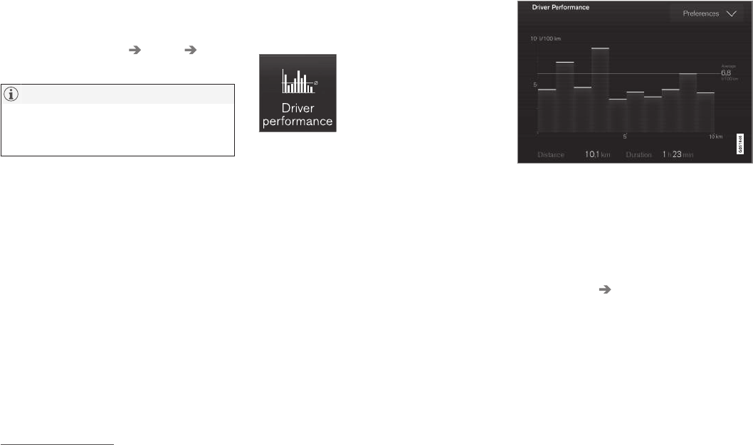
||
INSTRUMENTS AND CONTROLS
* Option/accessory, for more information, see Introduction.
94
Changing the unit of measure
Change the units of measure for driven distance
and fuel consumption in the center display's Top
view by selecting Settings System Units
and marking the desired unit.
NOTE
Changing these units of measure will also
change the ones used in the Volvo navigation
system*.
Related information
•Displaying trip statistics (p. 94)
•Trip computer (p. 92)
Displaying trip statistics
Trip computer statistics can be displayed graphi-
cally in the center display.
Open the Driver performance
app in the app menu to display
trip statistics.
Each bar in the graph repre-
sents a driving distance of
1 mile, 10 miles or 100 miles1
depending on the current scale; bars are added
from the right and the bar at the far right shows
the value for the current trip.
Average fuel consumption is calculated from the
most recent time at which the current trip odom-
eter was reset.
Trip statistic settings
Select Preferences to:
•change the graph's scale
•Reset data after each trip (this occurs if the
vehicle remains parked for more than 4
hours)
•Reset data for the current trip
The illustration is generic; the layout may vary depending
on the model or due to software updates
Changing the unit of measure
Change the units of measure for driven distance
and fuel consumption in the center display's Top
view.
1. Tap Settings in Top view.
2. Tap System Units.
3. Under Units, select: Metric, Imperial or US.
Related information
•Trip computer (p. 92)
•Displaying trip computer information (p. 93)
1This can also be displayed in kilometers.
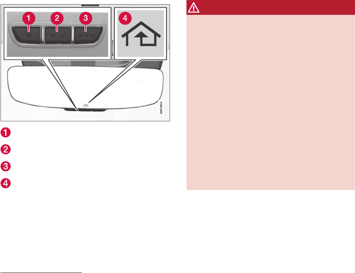
INSTRUMENTS AND CONTROLS
* Option/accessory, for more information, see Introduction. 95
HomeLink® Wireless Control
System*
HomeLink® can be used to open garage doors,
gates, etc.
Button 1
Button 2
Button 3
Indicator light
The HomeLink®2 Wireless Control System pro-
vides a convenient way to replace up to three
hand-held radio-frequency (RF) transmitters used
to activate devices such as gate operators,
garage door openers, entry door locks, security
systems, even home lighting. Additional informa-
tion can be found on the Internet at,
www.homelink.com/www.youtube.com/
HomeLinkGentex or by phoning the hotline at 1–
800–355–3515.
WARNING
•If you use HomeLink® to open a garage
door or gate, be sure no one is near the
gate or door while it is in motion.
•When programming a garage door
opener, it is advised to park outside of the
garage.
•Do not use HomeLink® with any garage
door opener that lacks safety stop and
reverse features as required by U.S. fed-
eral safety standards (this includes any
garage door opener model manufactured
before April 1, 1982). A garage door that
cannot detect an object - signaling the
door to stop and reverse - does not meet
current U.S. federal safety standards. For
more information, contact HomeLink at:
www.homelink.com.
Retain the original transmitter of the RF device
you are programming for use in other vehicles as
well as for future HomeLink programming. It is
also suggested that upon the sale of the vehicle,
the programmed HomeLink buttons be erased
for security purposes. See the article "Program-
ming HomeLink."
Related information
•Programming the HomeLink® Wireless Con-
trol System* (p. 96)
2HomeLink and the HomeLink house are registered trademarks of Gentex Corporation.

INSTRUMENTS AND CONTROLS
* Option/accessory, for more information, see Introduction.
96
Programming the HomeLink®
Wireless Control System*
HomeLink® can be used to open garage doors,
gates, etc.
NOTE
Some vehicles may require the ignition to be
switched on or be in the “accessories” posi-
tion for programming and/or operation of
HomeLink. It is also recommended that a new
battery be placed in the hand-held transmitter
of the device being programmed to Home-
Link for quicker training and accurate trans-
mission of the radio-frequency signal. The
HomeLink buttons must be reset first. When
this has been completed, Homelink is in
learning mode so that you can perform pro-
gramming.
To program HomeLink®
1. Press the HomeLink® button to be pro-
grammed. The HomeLink® indicator will
begin flashing yellow once a second. You do
not need to continue holding the button.
2. Point the hand-held transmitter toward the
HomeLink® button to be programmed and
hold it approx. 6–12 inches (15–30 cm)
away from the HomeLink® button. Do not
obstruct the HomeLink® indicator light.
3. Press and hold the button on the original
remote control that is to be programmed on
HomeLink® and observe the HomeLink®
indicator light. Hold the button until the indi-
cator light has changed from flashing yellow
once a second to either flashing green 10
times a second or by glowing steadily green.
When the HomeLink® indicator light flashes
or glows steadily green, the button on the
original remote control can be released.
Note: for certain remote controls, the
instructions listed under "Gate operators/
Canadian programming" at the end of this
article should be used instead of step 3.
4. Press the programmed HomeLink® button
and check the indicator light.
Indicator light glows steadily green: pro-
gramming has been completed. The garage
door, gate, etc., should now be activated
when the programmed button is pressed.
Indicator light flashes 10 times a second:
press the HomeLink® button that is being
programmed. Hold it for 2 seconds and
release it. Repeat the “press/hold/release”
sequence a second time, and, depending on
the brand of the garage door opener, repeat
this sequence a third time to complete the
programming process. Programming should
now be completed and the garage door,
gate, etc., should now be activated when the
programmed button is pressed.
If the garage door, etc. still does not
react: continue with steps 6-8 to complete
programming.
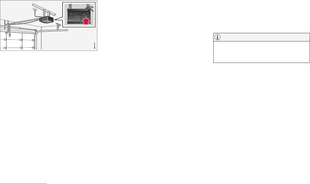
INSTRUMENTS AND CONTROLS
}}
97
5. Locate the "training" button on the garage
door opener, etc. The designation and color
of the button may vary, depending on the
manufacturer. It is usually located near the
antenna attachment on the device.
6. Press the device's "training" button. When
this has been done, step 8 must be comple-
ted within 30 seconds.
7. Press and hold the HomeLink® button being
programmed for 2 seconds and release it.
Repeat the “press/hold/release” sequence a
second time, and, depending on the brand of
the garage door opener, repeat this
sequence a third time to complete the pro-
gramming process. Programming should now
be completed and the garage door, gate, etc.,
should now be activated when the pro-
grammed button is pressed.
Gate Operator/Canadian Programming
Canadian radio-frequency laws require transmit-
ter signals to “time-out” (or quit) after several
seconds of transmission – which may not be long
enough for HomeLink to pick up the signal dur-
ing programming. Similar to this Canadian law,
some U.S. gate operators are designed to “time-
out” in the same manner.
If you live in Canada or you are having difficulties
programming a gate operator or garage door
opener by using the “Programming” procedures,
replace “Programming HomeLink” step 3
with the following:
•Continue to press and hold the HomeLink
button while you press and release - every
two seconds (“cycle”) your hand-held trans-
mitter until the HomeLink indicator light
changes from a slow to a rapidly blinking
light. Now you may release both the Home-
Link and hand-held transmitter buttons.
Proceed with “Programming” step 4 to complete.
Using HomeLink®
When programming has been completed,
HomeLink® can be used instead of the original
remote controls.
To operate, press and hold the programmed
HomeLink® button until the trained device begins
to operate3 (this may take several seconds). The
indicator light will glow steadily or flash when the
button has been pressed. Activation will now
occur for the trained device (i.e., garage door
opener, gate operator, security system, entry door
lock, home/office lighting, etc.).
NOTE
If the ignition is switched off, HomeLink will
function for 30 minutes after the driver's door
has been opened.
For convenience, the hand-held transmitter of the
device may also be used at any time.
In the event that there are still programming diffi-
culties or questions, contact HomeLink at:
www.HomeLink.com, www.youtube.com/
HomeLinkGentex or by phoning the hotline at 1–
800–355–3515.
Resetting HomeLink® buttons
Use the following procedure to reset (erase pro-
gramming) from the three HomeLink® buttons
(individual buttons cannot be reset but can be
“reprogrammed” as outlined in the following sec-
tion):
1. Press and hold HomeLink® buttons 1 and 3
for approx. 10 seconds until the indicator
light begins to flash green.
3Do not hold the button for more than 20 seconds as this will clear the programming of the button.
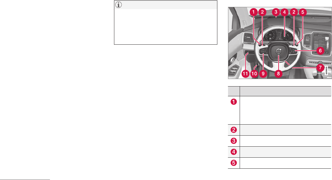
||
INSTRUMENTS AND CONTROLS
* Option/accessory, for more information, see Introduction.
98
2. Release both buttons.
>HomeLink® is now in the training (or
learning) mode and can be programmed
at any time beginning with “To program
HomeLink®" above.
Reprogramming a single HomeLink®
button
To reprogram an individual HomeLink® button:
1. Press and hold the desired HomeLink® but-
ton. DO NOT release the button.
2. The yellow indicator light will begin to flash
after 20 seconds. Without releasing the
HomeLink button, proceed with “To program
HomeLink®" step 1 above.
For questions or comments, contact HomeLink
at: www.HomeLink.com, www.youtube.com/
HomeLinkGentex or by phoning the hotline at 1–
800–355–3515.
FCC (USA) and IC (Canada)
This device complies with FCC rules part 15 and
Industry Canada RSS-210. Operation is subject
to the following two conditions: (1) This device
may not cause harmful interference, and (2) This
device must accept any interference that may be
received including interference that may cause
undesired operation. WARNING: The transmitter
has been tested and complies with FCC and IC
rules. Changes or modifications not expressly
approved by the party are prohibited.
NOTE
The transmitter has been tested and complies
with FCC and IC rules. Changes or modifica-
tions not expressly approved by the party
responsible for compliance could void the
user’s authority to operate the device.4
Related information
•HomeLink® Wireless Control System* (p. 95)
Instruments and controls
This overview shows the location of the primary
displays, and controls/buttons/switches.
Display/function/control
Parking lights, daytime running lights, low
beams, high beams, turn signals, front
fog lights/corner illumination*, rear fog
lights, trip computer reset
Transmission manual shifting paddle*
Head-up-display*
Instrument panel
Wipers/washers, rain sensor*
4The term “IC:” before the certification/registration number only signifies that Industry Canada technical specifications were met.
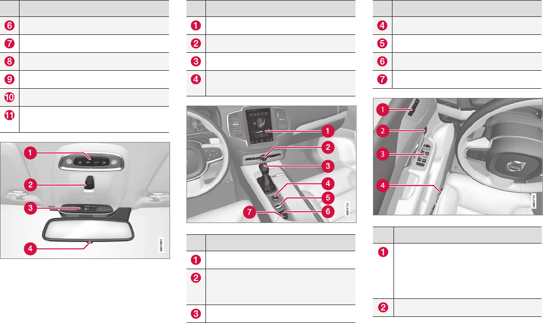
INSTRUMENTS AND CONTROLS
}}
* Option/accessory, for more information, see Introduction. 99
Display/function/control
Right-side steering wheel keypad
Steering wheel adjustment
Horn
Left-side steering wheel keypad
Hood open
Display lighting, tailgate unlock, tailgate
open*
Display/function/control
Front reading lights and courtesy lighting
Laminated panoramic roof*
Ceiling console display
Manual rearview mirror auto-dim (certain
markets only)
Display/function/control
Center display
Hazard warning flashers, max. defroster/
heated windshield*, media player, glove
compartment open
Gear selector
Display/function/control
Start knob
Drive modes
Parking brake
Auto-hold brakes
Display/function/control
Memory control for:
•power seats*
•door mirrors
•head-up display*
Door open, door/tailgate lock/unlock
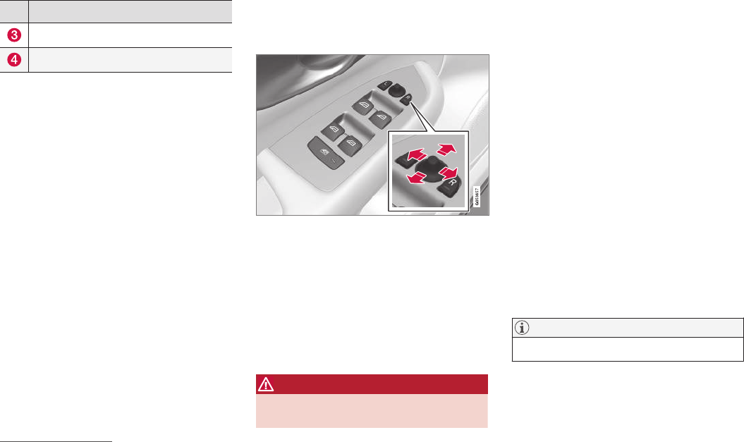
INSTRUMENTS AND CONTROLS
* Option/accessory, for more information, see Introduction.
100
Display/function/control
Power windows, power door mirrors
Controls for power front seat*
Adjusting the power door mirrors
The control on the driver's door is used to adjust
the position of the door mirrors.
Door mirror controls
Adjusting
1. Press the L button for the left door mirror or
the R button for the right door mirror. The
light in the button comes on.
2. Adjust the position with the joystick in the
center.
3. Press the L or R button again. The light
should no longer be on.
WARNING
Objects seen in the mirrors may appear fur-
ther away than they actually are.
Storing the position*
The mirror positions are stored in the key mem-
ory* when the vehicle has been locked with the
remote key. When the vehicle is unlocked with
the same remote key, the mirrors and the driver's
seat adopt the stored positions when the driver's
door is opened. The mirrors' position can also be
stored in the power seat's* memory.
Tilting the door mirrors when parking5
The door mirrors can be tilted down to help give
the driver a better view along the sides of the
vehicle, for example when parallel parking.
–To activate this function, select reverse gear
and press the L or R mirror control button to
tilt the mirror down.
The door mirror will reset to its normal position:
•after 10 seconds when reverse is disen-
gaged
•immediately if you press the corresponding L
or R button again.
NOTE
Only one mirror can be tilted down at a time.
5Only on models equipped with a power driver's seat.

INSTRUMENTS AND CONTROLS
* Option/accessory, for more information, see Introduction. 101
Automatically tilting the door mirrors
when parking5
This function can be activated/deactivated in the
center display.
1. Tap Settings in Top view.
2. Tap My Car Mirrors.
3. Under Tilt Mirror In Reverse, select Off,
Driver, Passenger or Both to activate/
deactivate and select which mirror to tilt.
Folding mirrors*
When parking in a limited space, the mirrors can
be folded in:
1. Press the L and R buttons at the same time
(the ignition must be in at least mode I).
2. Release the buttons after approx. 1 second.
The mirrors will stop automatically when they
are completely folded in.
Fold out the mirrors by pressing the L and R at
the same time. The mirrors will stop automatically
when they return to their original positions.
Automatic folding when the vehicle is
locked5
The mirrors can be folded in/out automatically
when the vehicle is locked/unlocked.
This function can be activated/deactivated in the
center display.
1. Tap Settings in Top view.
2. Tap My Car Mirrors.
3. Select Fold Mirrors When Locking to acti-
vate/deactivate.
Resetting the mirrors' position
A mirror that has been moved manually (e.g.,
bumped into in a parking lot, etc.) has to be
returned to its normal position electrically before
automatic folding will function correctly.
1. Fold in the mirrors with the L and R buttons.
2. Fold out the mirrors with the L and R buttons.
The mirrors have now been reset to their original
positions.
Auto-dim*
Settings can be made for the auto-dim function
in the rearview and door mirrors.
The auto-dim function is always active while the
vehicle is being driven except when the reverse
gear has been selected. The level of sensitivity
for this function can be set to three levels, which
affect the rearview mirror and door mirrors.
NOTE
When the level of sensitivity is changed, this
change will not be noticeable immediately but
will take effect after a short period of time.
The level of sensitivity is set from the center dis-
play:
1. Tap Settings in Top view.
2. Tap My Car Mirrors.
3. Under Auto Dim Mirrors, select Normal,
Dark or Light.
Related information
•Using the power seat memory function*
(p. 160)
•Rearview mirror (p. 106)
5Only on models equipped with a power driver's seat.
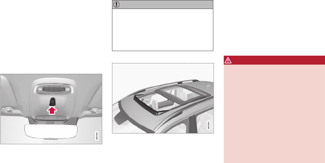
INSTRUMENTS AND CONTROLS
* Option/accessory, for more information, see Introduction.
102
Laminated panoramic roof*
The laminated panoramic roof is divided into two
sections and only the front section can be
opened; it can be slid horizontally to the open or
closed positions or its rear edge can be raised
and lowered to allow ventilation.
The laminated panoramic roof also has a sun
shade made of perforated fabric that is located
below the sections of glass. This shade can be
opened or closed, for example when driving in
bright sunlight.
The laminated panoramic roof and the sun shade
are operated using the controls in the ceiling
console, near the rear-view mirror. The controls
are activated when the vehicle's ignition is in
mode I or II.
CAUTION
•Remove ice and snow before opening the
laminated panoramic roof.
•Do not operate the laminated panoramic
roof if it is frozen closed.
•Never place heavy objects on the lamina-
ted panoramic roof.
Wind blocker
The laminated panoramic roof is equipped with a
wind blocker that folds up when the roof is open.
Related information
•Operating the laminated panoramic roof*
(p. 102)
Operating the laminated panoramic
roof*
When opened automatically, the sun shade and
roof open completely.
In the ventilation position, the rear edge of the
front section of the roof is raised.
Operation
WARNING
•During manual closing, if the laminated
panoramic roof is obstructed, immediately
open it again.
•Never open or close the laminated panor-
amic roof if it is obstructed in any way.
•Never allow a child to operate the lamina-
ted panoramic roof.
•Never leave a child alone in a vehicle.
•When leaving the vehicle, ensure that the
ignition is in mode 0. Never leave a
remote key in the vehicle.
•Never extend any object or body part
though the open laminated panoramic
roof, even if the vehicle's ignition is com-
pletely switched off.
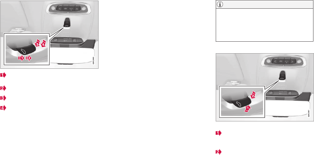
INSTRUMENTS AND CONTROLS
}}
103
Manual open (arrow points toward the rear of
the vehicle)
Auto open
Manual close
Auto close
The laminated panoramic roof and sun shade can
be operated when the ignition is in mode I or II.
Automatic operation
1. To open the sun shade completely, pull the
control as far back as possible (to the auto
open position) and release it.
2. To fully open the laminated panoramic roof,
pull the control as far back as possible a
second time (to the auto open position) and
release it.
Perform this procedure in reverse order to close
the laminated panoramic roof and/or sun shade.
Quick open/close
The laminated panoramic roof and the sun shade
can be opened/closed at the same time:
•Open: pull the control back (to the auto
open position) twice in quick succession and
release it.
•Close: push the control forward (to the auto
close position) twice in quick succession and
release it.
Manual operation
1. Opening the sun shade: Pull the control
back to the first stop (the manual open posi-
tion) and hold it until the sun shade has
opened to the position of your choice.
2. Opening the rear edge of the laminated
panoramic roof: Pull the control back to the
first stop (the manual open position) a sec-
ond time to open the rear edge of the lami-
nated panoramic roof.
3. Opening the front glass section: Pull the
control back to the first stop (the manual
open position) a third time and hold it until
the laminated panoramic roof has opened to
the position of your choice.
Perform this procedure in reverse order to close
the laminated panoramic roof and/or sun shade.
NOTE
For manual opening, the sun shade must first
be fully open before it will be possible to open
the laminated panoramic roof. When closing,
the laminated panoramic roof must be fully
closed before the sun shade can be closed.
Tilt (ventilation) position
Tilt position, raised at the rear edge
Open (raise the rear edge of the front glass
section) by pressing the rear edge of the
control upward.
Close by pulling the rear edge of the control
downward/forward and holding it until the
laminated panoramic roof has closed com-
pletely.
If the sun shade is completely closed, it will open
approximately 2 inches (5 cm) when the lamina-
ted panoramic roof is opened to the tilt position.
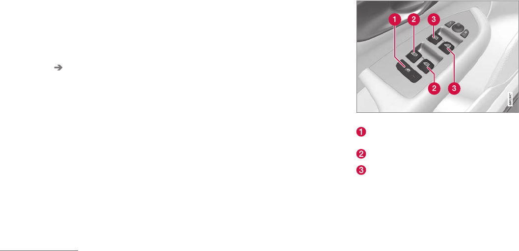
||
INSTRUMENTS AND CONTROLS
* Option/accessory, for more information, see Introduction.
104
Automatically closing the sun shade6
When the vehicle is parked in sunny/warm
weather, the sun shade can be closed automati-
cally 15 minutes after the vehicle has been
locked to help keep the temperature in the pas-
senger compartment down and to protect the
upholstery from the sun.
This function is deactivated by default and can be
activated/deactivated:
1. Tap Settings in the center display's Top
view.
2. Tap My Car Locking.
Select Auto Close Sun Curtain to acti-
vate/deactivate.
Auto-stop
The laminated panoramic roof has an auto-stop
feature that is triggered if the glass section of the
roof or the sun shade is blocked in any way when
being closed. In this case, the laminated panor-
amic roof or sun shade will stop and reverse
automatically approximately 2 in. (5 cm) from the
point at which it was blocked (or will open fully to
the tilt position).
The auto-stop feature also functions when the
laminated panoramic roof or sun shade is being
opened.
The auto-stop feature can be overridden if the
closing procedure has been interrupted (e.g., due
to ice around the laminated panoramic roof) by
pressing and holding the control forward/down
until the roof is closed.
Power windows
All power windows can be operated using the
control panel in the driver's door. The control
panels in the other doors only operate the win-
dow in the respective doors.
Driver's door control panel
Switch for power child safety locks* and dis-
engaging rear power window buttons
Rear window controls
Front window controls
Related information
•Operating the power windows (p. 105)
•Child safety locks (p. 218)
6Not available in all markets

INSTRUMENTS AND CONTROLS
}}
105
Operating the power windows
All power windows can be operated using the
control panel in the driver's door. The control
panels in the other doors only operate the win-
dow in the respective doors.
WARNING
•Always put the ignition in mode 0 and
remove the ignition key from the vehicle
when the vehicle is unattended
•Never leave children unattended in the
vehicle.
•Make sure that the windows are com-
pletely unobstructed before they are
operated.
Operating
Operating the power windows
Manual up/down
Auto up/down.
For the power windows to function, the ignition
must be in at least mode I. When the vehicle has
been running, the power windows can be oper-
ated for several minutes after the ignition has
been switched off, or until a door has been
opened.
NOTE
•Movement of the windows will stop if they
are obstructed in any way. If this happens
twice in succession, the automatic func-
tion will not work for several minutes and
the window can be closed by holding the
button up.
•To reduce buffeting wind noise if the rear
windows are opened, also open the front
windows slightly.
Manual up/down
–Move one of the controls up/down slightly.
> The power windows move up/down as
long as the control is held in position.
Auto up/down
–Move one of the controls up/down as far as
possible and release it.
> The window will open or close completely.
Resetting
If the battery has been disconnected, the auto
open function must be reset so that it will work
properly
1. Gently raise the front section of the button to
close the window and hold it for one second.
2. Release the button briefly.
3. Raise the front section of the button again
for one second.
||
INSTRUMENTS AND CONTROLS
106
Related information
•Child safety locks (p. 218)
Rearview mirror
The interior rearview mirror has an auto-dim
function that helps reduce glare from following
vehicle's headlights.
Auto-dim function
The auto-dim function is controlled by two sen-
sors: one pointing forward (located on the for-
ward-facing side of the mirror, which monitors the
amount of ambient light) and one pointing rear-
ward (located on the side of the mirror facing the
driver at the upper edge, which senses the
strength of following vehicles' headlights), and
work together to help eliminate glare.
NOTE
Obstructing the forward sensor with e.g.,
parking stickers, transponders, etc., or the rear
sensor by loading the cargo area or the rear
seat in such a way that light is prevented from
reaching the sensor will reduce the auto-dim
function in the interior rearview mirror and
optional auto-dim function in the door mirrors.
The auto-dim function is always active while the
vehicle is being driven except when the reverse
gear has been selected. The level of sensitivity
for this function can be set to three levels, which
affect the rearview mirror and door mirrors.
NOTE
When the level of sensitivity is changed, this
change will not be noticeable immediately but
will take effect after a short period of time.
The level of sensitivity is set from the center dis-
play:
1. Tap Settings in Top view.
2. Tap My Car Mirrors.
3. Under Auto Dim Mirrors, select Normal,
Dark or Light.
Related information
•Adjusting the power door mirrors (p. 100)
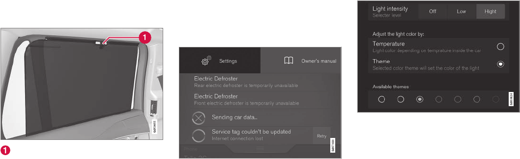
INSTRUMENTS AND CONTROLS
}}
107
Using sun shades
Both rear doors have integrated sun shades.
Rear doors
Hook and locking mechanism
1. Pull up the sun shade and hook it to the
upper section of the door frame.
2. Lock the sun shade by moving the locking
mechanism upward.
The window can be opened/closed when the sun
shade is being used.
Settings view
The center display's Settings view is used to
make many of the vehicle's function settings and
to display vehicle-related information.
Opening Settings view
Top view with the Settings button
1. Pull down the tab on the upper edge of the
center display to open Top view.
2. Tap Settings.
3. Tap one of the categories displayed and nav-
igate to sub-categories and settings by tap-
ping again.
4. Tap Back to go back in Settings view.
Tap Close to close Settings view.
Changing a setting
A sub-category in Settings view with various possible
settings
1. Tap the category/sub-category to navigate to
the desired setting.
2. Change the setting(s).
> The changes are saved immediately.

||
INSTRUMENTS AND CONTROLS
* Option/accessory, for more information, see Introduction.
108
Types of settings
Type of
setting
Description
Trigger
function
Starts an app or a separate view
for more advanced settings. Tap
the text to e.g., connect a
Bluetooth device.
Radio
button
Select one of the possible set-
tings by tapping the desired radio
button to e.g., change the system
language.
Multi-
selection
button
Select a level for a particular set-
ting by pressing the desired part
of the button e.g., to set the
desired level for City Safety.
Check
box
Tap to activate/deactivate a func-
tion e.g., to select automatic start
for steering wheel heating.
Slider Select a level for a function by
pressing and dragging the slider
control e.g., to set a volume level.
Informa-
tion dis-
play
This is not an actual setting but
displays information such as the
vehicle's VIN number.
Related information
•Center display overview (p. 28)
•Navigating in the center display's views
(p. 38)
•Using the center display (p. 45)
•Changing system settings in Settings view
(p. 110)
•Categories in Settings view (p. 108)
Categories in Settings view
Settings view consists of a number of main cate-
gories and sub-categories that contain settings
and information for many of the vehicle's fea-
tures and functions.
The main categories in Settings view are: My
Car, Sound, Navigation, Media,
Communication, Climate and System.
Each main category, in turn, contains several sub-
categories with possible settings. The table
shows the first level of sub-categories. The possi-
ble settings for a function or area are described
in greater detail in their respective articles in the
owner's manual. For system settings not descri-
bed in the respective articles, see "Changing sys-
tem settings in Settings view."
My Car
Sub-categories
Displays
IntelliSafe
Park Assist
Drive Mode/Individual Drive Mode*
Lights
Mirrors
Locking and Unlocking Feedback

INSTRUMENTS AND CONTROLS
* Option/accessory, for more information, see Introduction. 109
Sub-categories
Electric Parking Brake
Seats
Wipers
Suspension
Exterior SoundA
AXC90 T8 Plug-in Hybrid, certain markets only.
Sound
Sub-categories
Sound Experience*
Tone
Balance
System Volumes
Navigation
Sub-categories
Map
Route
Traffic
Guidance
System
Media
Sub-categories
AM/FM RadioA
SiriusXM
Gracenote®
Video
AAM radio is not available in hybrid models.
Communication
Sub-categories
Phone
Text Messages
Bluetooth
Wi-Fi
Vehicle Wi-Fi Hotspot
Vehicle Modem Internet
Volvo On Call
Volvo Service Networks
Climate
The main category Climate has no sub-catego-
ries.
System
Sub-categories
Date & Time
Language
Keyboard Layouts
Voice Control
Units
Storage
Software Updates
Factory reset
Services
Related information
•Settings view (p. 107)
•Changing system settings in Settings view
(p. 110)

INSTRUMENTS AND CONTROLS
* Option/accessory, for more information, see Introduction.
110
Changing system settings in
Settings view
Settings view's main category System contains
general settings and information, such as lan-
guage, units of measure, etc.
The system settings under Driver Profile, Date
& Time, Keyboard Layouts, Voice Control,
Software Updates, Factory reset and
Services are described in their respective arti-
cles in the owner's manual.
Changing system languages
1. Pull down the center display's Top view and
tap Settings.
2. Tap System Language.
3. Select a new system language. Languages
that can be used for voice commands are
indicated by a voice control symbol.
> This change affects the language used in
the instrument panel, center display and
the head-up display*.
Changing units of measure
Changing length and volume units
1. Pull down the center display's Top view and
tap Settings.
2. Tap System Units Units.
3. Select one of the following measurement
standards:
•Metric: kilometers, liters and degrees Cel-
sius.
•Imperial: miles, gallons and degrees Cel-
sius.
•US: miles, gallons and degrees Fahren-
heit.
> This change affects the units of measure
used in the instrument panel, center dis-
play and the head-up display*
Changing tire inflation pressure units
1. Pull down the center display's Top view and
tap Settings.
2. Tap System Units Tire Pressure.
3. Select a unit of measure for tire pressure.
> This changes the tire inflation pressure
units used in the Car status app in the
center display.
Viewing storage information
1. Pull down the center display's Top view and
tap Settings.
2. Tap System Storage.
> Storage information for the vehicle's hard
drive will be displayed, including total
capacity, available capacity and the
amount of storage space used by the
apps that have been installed.
Viewing the VIN (Vehicle Identification
Number)
1. Pull down the center display's Top view and
tap Settings.
2. Tap System Vehicle Identification
Number.
> The vehicle's VIN will be displayed.

INSTRUMENTS AND CONTROLS
111
Changing settings in apps
App view, which is one of the center display's
basic views, contains all of the apps installed in
the vehicle. From Home view, navigate to App
view by swiping the screen from right to left.
Apps for integrated (basic) functions
Certain apps in your vehicle are factory-installed,
such as FM, USB and CD and are part of Sen-
sus. Settings in these apps can be changed in
the center display's Top view.
Changing settings for a basic app
1. Tap one of the basic apps, for example FM
radio.
2. Pull down Top view.
3. Tap FM Radio Settings.
4. Change the desired settings and confirm.
5. Press the Home button below the center dis-
play or tap the screen outside of Top view or
pull up Top view to return to your original
view. See also the article "Categories in Set-
tings view."
Third party apps
Third party apps have to be downloaded e.g.,
Volvo ID. Settings for these apps are made in
the apps themselves, not in Top view.
Related information
•Settings view (p. 107)
•Navigating in the center display's views
(p. 38)
•Categories in Settings view (p. 108)
Resetting the settings view
All of the changes made under Settings view
can be reset to their default values at the same
time.
Resetting
1. Tap Settings in the center display's Top
view.
2. Tap System Factory reset.
3. Tap OK to confirm your choice.
Related information
•Settings view (p. 107)
•Resetting user data when the vehicle
changes owners (p. 112)
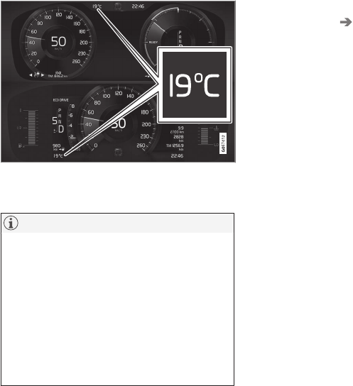
INSTRUMENTS AND CONTROLS
112
Resetting user data when the
vehicle changes owners
When the vehicle changes owners, all user set-
tings should be reset to the factory defaults.
When the vehicle changes owners, it is essential
to reset all user data and system settings to their
factory defaults, including Volvo On Call.
Related information
•Resetting the settings view (p. 111)
•Volvo ID (p. 26)
•Changing ownership of a vehicle with Volvo
On Call (p. 432)
Ambient temperature sensor
The ambient temperature sensor displays the
temperature outside the vehicle in the instrument
panel.
Location of the ambient temperature sensor in 12"
(upper) and 8" (lower) instrument panels (temperature
shown here in degrees Celsius)
NOTE
When the ambient temperature is between
23° and 36 °F (–5° and +2 °C), a snowflake
symbol will be displayed next to the tempera-
ture. This symbol serves as a warning for pos-
sible slippery road surfaces. Please note that
this symbol does not indicate a fault with your
vehicle.
At low speeds or when the vehicle is not mov-
ing, the temperature readings may be slightly
higher than the actual ambient temperature.
Settings
Changing measurement standard in the center
display:
1. Pull down the center display's Top view and
tap Settings.
2. Tap System Units.
3. Select measurement standard, Metric,
Imperial or US.
Related information
•Instrument panel (p. 123)
•Climate system sensors (p. 175)
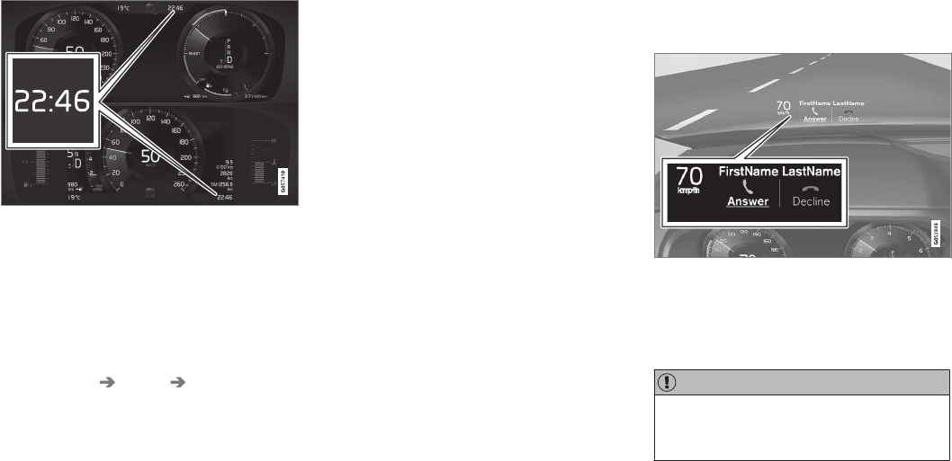
INSTRUMENTS AND CONTROLS
}}
* Option/accessory, for more information, see Introduction. 113
Clock
The clock is displayed in the instrument panel
and in the center display.
Location of the clock in the instrument panel in 12"
(upper) and 8" (lower) instrument panels
Certain messages and other information in the
instrument panel may temporarily obscure the
clock.
In the center display, the clock is located at the
upper right of the status bar.
Settings for date and time
Select Settings System Date & Time in
the center display's Top view to change the for-
mat for displaying date or time.
Set the date and time by tapping the up or down
arrows on the center display.
Automatic time
The function Automatic Time is also available,
which adjusts the time zone automatically,
depending on the vehicle's location. If Automatic
Time has not been selected, set the date and
time manually by tapping the up or down arrows
on the center display.
Daylight savings time
In certain countries, an automatic change to day-
light savings time can be selected by activating
Auto. If the automatic change is not available,
change to daylight savings time by selecting On
or Off.
Related information
•Instrument panel (p. 123)
•Center display overview (p. 28)
•Using the center display (p. 45)
Head-up display (HUD)*
The head-up display provides information such
as speed, cruise control functions, navigation,
traffic sign information, incoming phone calls,
etc. at the base of the windshield in the driver's
field of vision.
Incoming phone call
The HUD supplements the instrument panel and
projects information on the lower section of the
windshield. The projected information can only be
seen from the driver's seat.
CAUTION
The HUD's projection unit is located in the
dashboard. Avoid scratching or placing
objects on the unit's glass surface.
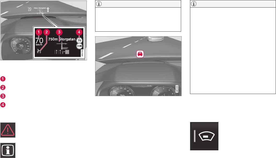
||
INSTRUMENTS AND CONTROLS
114
Example of information in the head-up display. The infor-
mation shown is generic and may vary slightly from mar-
ket to market or in terms of units of measure
Speed
Cruise control
Navigation
Road signs
Symbols such as the following ones may appear
temporarily in the HUD.
If the warning symbol appears, read the
warning text in the instrument panel.
If the information symbol appears, read
the warning text in the instrument
panel.
NOTE
If the City Safety is activated, the information
in the HUD will be replaced by a City Safety-
related graphic. This graphic will illuminate
even if the HUD is turned off.
A graphic for the City Safety flashes to attract the driv-
er's attention
NOTE
The driver's ability to see information in the
HUD may be impeded by:
•the use of polarizing sunglasses
•not sitting in the center of the driver's
seat
•objects on the HUD projector glass on
the dashboard
•certain ambient lighting conditions
•certain types of vision problems, which
may also result in headaches or eye
strain.
•Activating/deactivating and settings for
HUD are only possible when an image is
projected on the windshield. The engine
must be running.
Activating/deactivating HUD
HUD can be activated in two ways in the center
display:
Via Function view
Tap the Head-up display but-
ton.
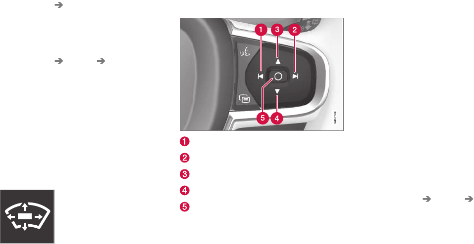
INSTRUMENTS AND CONTROLS
}}
* Option/accessory, for more information, see Introduction. 115
Via settings
1. Tap Settings in Top view.
2. Tap My Car Displays.
3. Select/deselect Head-Up Display.
Selecting display alternatives
1. Tap Settings in Top view.
2. Tap My Car Displays Head-Up
Display Options.
Tap Go to the center display's Settings view
and select Driver Display & Head-up
Display.
3. Select : Show Navigation In Head-Up
Display, Road Sign Information In Head-
Up Display, Show Driver Support In
Head-Up Display or Show Phone In
Head-Up Display.
Adjusting HUD brightness and height
position
1. Tap Head-up display adjustments in the
center display's Function view.
2. Use the right-side steering wheel keypad to
adjust the HUD's brightness and height posi-
tion on the windshield in the driver's field of
vision.
Reduce brightness
Increase brightness
Higher position
Lower position
Confirm
Adapting brightness
The brightness of the graphics displayed in the
HUD are also automatically adjusted according to
ambient lighting conditions. HUD brightness is
also affected by adjustments to the brightness of
the other displays in the vehicle.
Power front seat* memory function
The position of the HUD can be stored in the
power seat's memory function.
Replacing the windshield
Vehicles with a head-up display have a special
type of windshield meeting the requirements for
displaying projected information.
If the windshield has to be replaced, contact a
trained and qualified Volvo service technician or
authorized workshop. The correct type of replace-
ment windshield must be used for a head-up dis-
play.
Calibrating the horizontal position
If the windshield has been replaced, it may be
necessary to calibrate the HUD's horizontal posi-
tion. This means that the projected image will
have to be rotated clockwise or counterclockwise.
To do so:
1. Pull down the center display's Top view and
tap Settings.
2. Select My Car Displays Head-Up
Display Calibration.
3. Use the buttons on the right-side steering
wheel keypad to calibrate the horizontal posi-
tion.
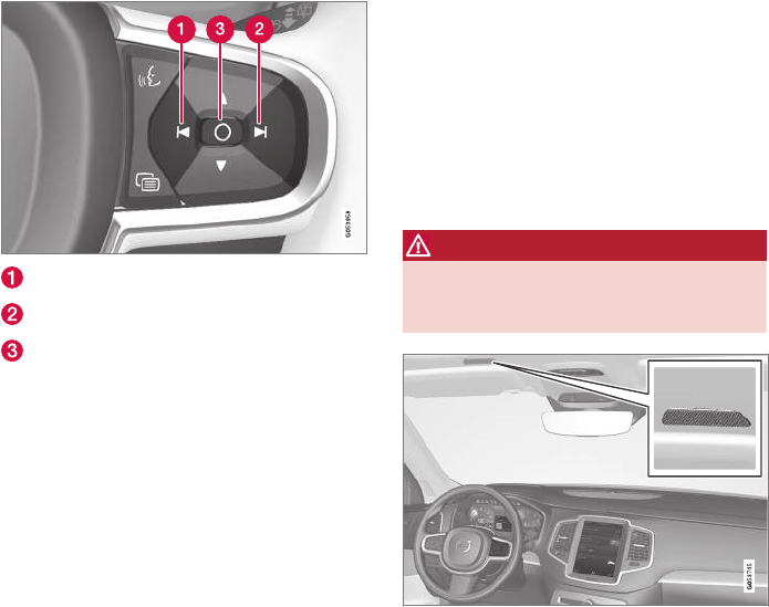
||
INSTRUMENTS AND CONTROLS
* Option/accessory, for more information, see Introduction.
116
Rotate counterclockwise
Rotate clockwise
Confirm
Cleaning
Wipe the glass covering the HUD projection unit
carefully with a clean and dry (or very slightly
damp if necessary) microfiber cloth.
Never use strong stain removers. For difficult
cleaning conditions, a special cleaning agent can
be purchased at a Volvo retailer.
Related information
•Center display overview (p. 28)
•Navigating in the center display's views
(p. 38)
Voice control
Voice commands make it possible for the driver
to voice-control certain functions in the media
player, a Bluetooth-connected cell phone, cli-
mate system and the Volvo navigation system*.
Voice control offers convenience and enables the
driver to keep his/her hands on the steering
wheel and concentrate on driving and the traffic
situation around the vehicle.
WARNING
As the driver, you have full responsibility for
operating the vehicle safely and adhering to
all applicable traffic regulations.
Input to the system is in dialog form and compri-
ses commands from the driver and a verbal
response from the system.
The voice control system uses the same micro-
phone as the Bluetooth hands-free system and
system responses come via the infotainment sys-
tem's speakers.
In certain cases, text messages are also provided
in the instrument panel.
The functions are controlled using the right-side
steering wheel keypad and settings are made
from the center console.
System updates
The voice control system is being constantly
improved and updates should be downloaded for
optimal functionality. See the support site
support.volvocars.com.
Related information
•Using voice commands (p. 117)
•Voice control settings (p. 121)
•Voice control for radio and media (p. 118)
•Voice control for cell phones (p. 118)
•System updates (p. 498)
•Navigation system voice commands (p. 120)
•Climate system voice commands (p. 119)
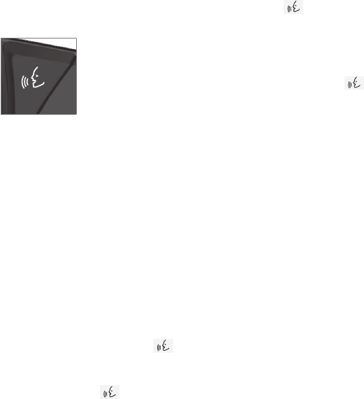
INSTRUMENTS AND CONTROLS
117
Using voice commands
The following is an introduction for using voice
commands.
Press the button on the right-
side steering wheel keypad to
activate the system and initiate
a voice command dialog.
Keep the following points in mind when using
voice commands:
•When giving a command, speak at your usual
speed and in a normal tone of voice after
the tone.
•Avoid speaking while the system is respond-
ing. Commands cannot be processed during
a response.
•Avoid background noises in the cabin when
using the system by closing the vehicle's
doors, windows and panoramic roof* when
giving voice commands.
Voice command dialogs can be cancelled by:
•Saying "Cancel".
•By pressing and holding the button on
the right-side steering wheel keypad.
To speed up a command dialog or to skip system
responses, press the button on the right-
side steering wheel keypad when the system is
responding and give your next command.
Voice command examples
Press , say "Call"-"[First-name]"-"[Last-
name]"-"[number category]" to call a contact
in your phonebook if the person has more than
one phone number listed (i.e., home, mobile, work,
etc.).
For example, press and say
"Call"-"Robin"-"Smith"-"mobile".
Commands/phrases
The following commands can always be used:
•Repeat: the system will repeat the most
recent voice instruction.
•Cancel: cancel the dialog.
•Help: Initiates a help dialog. The system will
provide several alternative commands that
can be used in a given situation.
The commands for specific situations are descri-
bed in the respective articles such as "Cell phone
commands", etc.
Numbers
Numbers can be spoken in different ways
depending on the context and function being
used:
•Phone numbers and zip codes should be
spoken individually, number by number, e.g.,
five five five one two three four (5551234).
•Addresses (house numbers) can be spo-
ken individually or as a group, e.g., two two or
twenty-two (22). It is also possible to say a
sequence of numbers, e.g., twenty-two
twenty-two (22 22) and "double" or "triple"
can also be used, e.g., double zero (00) or tri-
ple zero (000). Numbers in the range
0-2300 can be used.
•Frequencies can be spoken ninety-eight
point eight (98.8), one hundred four point
two (104.2) or hundred four point two
(104.2).
Related information
•Voice control (p. 116)

INSTRUMENTS AND CONTROLS
* Option/accessory, for more information, see Introduction.
118
Voice control for cell phones
Voice commands can be used to control many
of the most common functions in a Bluetooth®-
connected cell phone.
To specify a phone book contact, the voice com-
mand has to include the contact's information
that is in the phone book. For example, if a con-
tact such as John Smith has several phone
numbers, a number category such as home or
mobile can be specified. To call, say: "Call John
Smith mobile".
To use the voice control system, press the
on the right-side steering wheel keypad and say
one of the following commands after the tone:
•"Call [contact]": call a contact from your
phone book.
•"Call [phone number]": call a phone num-
ber.
•"Recent calls": displays the list of recent
calls.
•"Read message": reads a message aloud.
If there are several messages, select the one
to be read.
Related information
•Voice control (p. 116)
•Using voice commands (p. 117)
•Voice control settings (p. 121)
Voice control for radio and media
The following voice commands can be used for
the radio or an external media player.
To use the voice control system, press the
on the right-side steering wheel keypad and say
one of the following commands after the tone:
•"Media": initiates a dialog and displays pos-
sible commands.
•"Play [artist]": plays music by the selected
artist.
•"Play [song title]": plays the selected song.
•"Play [song title] from [album]": plays the
selected song from the selected album.
•"Play [radio station]": starts the selected
radio station.
•"Tune to [frequency]": tunes to the
selected frequency on the current waveband.
If no waveband has been selected, FM is the
default.
•"Tune to [frequency] [waveband]": tunes
to the selected station on the selected wave-
band.
•"Radio": starts FM radio.
•"Radio FM": starts FM radio.
•"Radio AM": starts AM radio.
•"SiriusXM": starts SiriusXM radio*
•"CD": starts playback from a CD.
•"USB": starts playback from a USB flash
drive.
•"iPod": starts playback from an iPod.
•"Bluetooth": starts playback from a Blue-
tooth-connected device.
•"Similar music": starts playback from a
USB flash drive with music similar to the type
currently playing.
Related information
•Voice control (p. 116)
•Using voice commands (p. 117)
•Voice control settings (p. 121)

INSTRUMENTS AND CONTROLS
* Option/accessory, for more information, see Introduction. 119
Climate system voice commands
Voice commands can be used to control the cli-
mate system to e.g., change the temperature,
activate seat heating* or change blower (fan)
speed.
To use the voice control system, press the
on the right-side steering wheel keypad and say
one of the following commands after the tone:
•"Climate": starts a command dialog and
provides examples of commands that can be
used.
•"Set temperature to X degrees": sets the
desired temperature.
•"Raise temperature"/"Lower
temperature": raises/lowers the tempera-
ture.
•"Sync temperature": synchronizes the tem-
perature in all of the vehicle's climate zones
with the one set for the driver's side.
•"Air on feet"/"Air on body": opens the
desired air vent.
•"Air on feet off"/"Air on body off": closes
the desired air vent.
•"Set fan to max"/"Turn off fan": changes
the blower speed to Max/Off.
•"Raise fan speed"/"Lower fan speed":
raises/lowers the blower speed.
•"Turn on auto": activates automatic climate
control.
•"Air condition on"/"Air condition off":
activates/deactivates the air conditioning.
•"Recirculation on"/"Recirculation off":
activates/deactivates recirculation.
•"Turn on defroster "/"Turn off defroster":
activates/deactivates window and door mirror
defrosting.
•"Turn on max defroster"/"Turn off max
defroster": activates/deactivates max
defroster.
•"Turn on electric defroster"/"Turn off
electric defroster": activates/deactivates
the electrically heated windshield*.
•"Turn on rear defroster"/"Turn off rear
defroster": activates/deactivates the electri-
cally heated rear window and door mirrors.
•"Turn steering wheel heat on"/"Turn
steering wheel heat off": activates/deacti-
vates the electrically heated steering wheel*.
•"Raise steering wheel heat"/"Lower
steering wheel heat": raises/lowers the
heating level for the electrically heated steer-
ing wheel*.
•"Turn on seat heat"/"Turn off seat heat":
activates/deactivates the electrically heated
seats*.
•"Raise seat heat"/"Lower seat heat": rai-
ses/lowers the heating level for the electri-
cally heated seats*.
•"Turn on seat ventilation"/"Turn off seat
ventilation": activates/deactivates seat ven-
tilation*.
•"Raise seat ventilation"/"Lower seat
ventilation": raises/lowers the level for seat
ventilation*.
Related information
•Climate system controls (p. 178)
•Voice control (p. 116)
•Using voice commands (p. 117)

INSTRUMENTS AND CONTROLS
120
Navigation system voice commands
Many of the navigation system's functions can
be activated using voice commands.
The procedure for using voice control is descri-
bed in greater detail in the articles "Voice con-
trol," "Using voice control" and "Voice control
settings."
Voice commands
The following list contains examples of com-
mands that are unique to navigation system.
To use the voice control system, press the
on the right-side steering wheel keypad and say
one of the following commands after the tone:
•"Navigation: Starts a navigation voice com-
mand dialog and displays available com-
mands.
•"Take me home: Guidance will be given to
the location set as Home.
•"Go to [City]: Enter a city as a destination,
e.g., "Go to New York."
•"Go to [Address]: Enter an address as a
destination, e.g., Go to 125 43 St., New
York."
•"Go to Intersection": Enter an intersection
as a destination. The search for the intersec-
tion will be done within the specified area.
•"Go to [Zip code]: Enter a zip code as a
destination, e.g., "Go to 07405."
•"Go to [Name]: Enter a name from a list of
contacts e.g., "Go to John Smith."
•"Search [POI category]: Search for a POI
(e.g., a restaurant)7, which is always sorted
according to POIs "around the vehicle." To
search along the route, say "Along the
route" when the list of results is displayed.
•"Change country/Change state: Changes
the country/state in which a search is con-
ducted.
•"Show favorites: Shows a list of Favorites
in the center display's Top view.
•"Clear itinerary: Deletes all intermediate
destinations in an itinerary.
•"Repeat voice guidance: Repeats the most
recent guidance instruction.
•"Pause guidance: Pauses guidance on the
map.
•"Resume guidance: Resumes guidance on
the map.
•"Turn off voice guidance: Turns voice navi-
gation guidance off.
•"Turn on voice guidance: Turns voice navi-
gation guidance on.
Related information
•Navigation displays and controls (p. 441)
•Voice control (p. 116)
•Using voice commands (p. 117)
•Voice control settings (p. 121)
7You can opt to call the POI or set it as a destination.
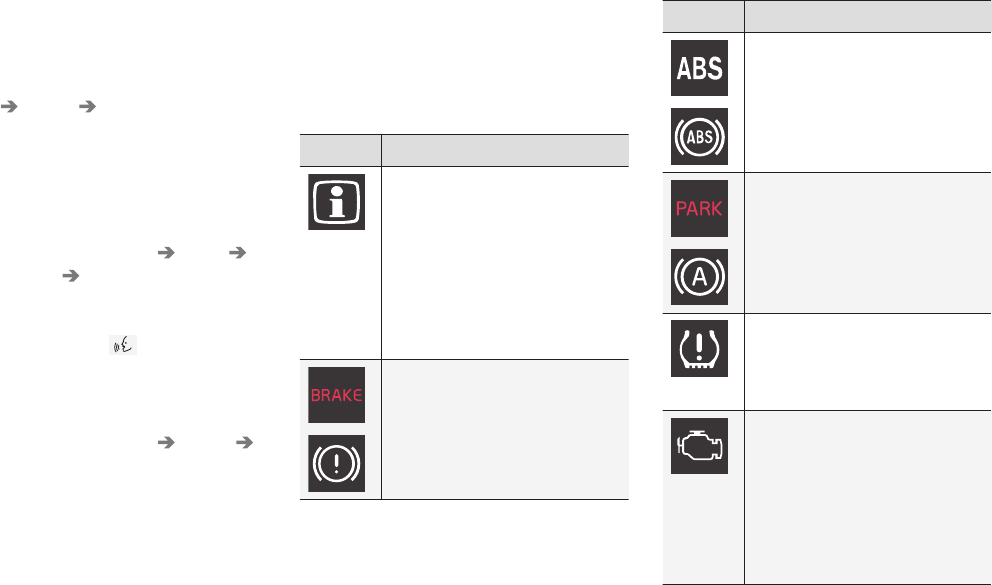
INSTRUMENTS AND CONTROLS
}}
121
Voice control settings
There are a number of settings that can be made
for the voice control system.
Open the center display's Top view and tap
Settings System Voice Control and
select settings.
•Repeat Mode
•Gender
•Speech Rate
Sound settings
Open Top view and tap Settings Sound
System Volumes Voice Control.
Changing languages
The voice control system only understands the
languages marked by the symbol in the list
of possible system languages.
Changing the language for this system also
affects menus, messages and help texts.
Open Top view and tap Settings System
Language.
Related information
•Voice control (p. 116)
•Using voice commands (p. 117)
•Navigation system voice commands (p. 120)
Indicator symbols in the instrument
panel
The indicator symbols alert the driver when cer-
tain functions are activated, that a system is
actively working or that a fault may have occur-
red in a system or function.
Symbol Explanation
Information, see the text mes-
sage in the instrument panel
The information symbol illuminates
in combination with a text mes-
sage if one of the vehicle's sys-
tems requires the driver's atten-
tion. The information symbol can
also illuminate in combination with
other symbols.
A
B
Brake system
Symbol Explanation
A
B
ABS brake system
This symbol indicates a possible
fault in the ABS braking function.
The vehicle's normal brakes will
still function but without ABS
brake modulation.
A
B
Parking brake/Auto-brake
This function keeps the vehicle at
a standstill after it has stopped.
The symbol is on when the func-
tion is activated and the brakes or
parking brake are being used.
Tire pressure system
The symbol illuminates to indicate
low tire pressure or a fault in the
tire pressure system.
Malfunction indicator light
(check engine light)
This symbol will illuminate if there
is a fault in the emissions control
system. If this happens, please
have your vehicle checked by a
trained and qualified Volvo service
technician as soon as possible.

||
INSTRUMENTS AND CONTROLS
122
Symbol Explanation
Left/right turn signals
Both turn signal indicators will
flash when the hazard warning
flashers are being used.
Forward lights
Active Bending Lights (ABL)
This symbol will illuminate if there
is a fault in the ABL system.
Automatic/active high beams
on
The symbol will be blue when the
automatic high beams are on.
Automatic/active high beams
offThe symbol will be white when
the automatic high beams are off.
High beam indicator
The symbol will illuminate when
the high beams are on or when
high beam flash is being used.
Symbol Explanation
Automatic/active high beams
on
The symbol will be blue when the
automatic high beams are on. The
parking lights will also be on.
Automatic/active high beams
off
The symbol will be white when the
automatic high beams are off. The
parking lights will be on.
High beams on
The high beams and parking lights
will be on.
Front fog lights
The symbol illuminates when the
front fog lights are on.
Rear fog lights
The symbol illuminates when the
rear fog lights are on.
Rain sensor
The symbol illuminates when the
rain sensor is on.
Symbol Explanation
Not in use
Stability system
This symbol flashes when the sta-
bility system is actively working to
stabilize the vehicle. If the symbol
glows steadily, there is a fault in
the system.
Stability system, sport mode
This symbol illuminates when
Sport mode is on. Sport mode
offers more active driving charac-
teristics by monitoring movement
of the accelerator pedal, steering
wheel and cornering by allowing
more lateral movement of the rear
wheels before the stability system
is activated.
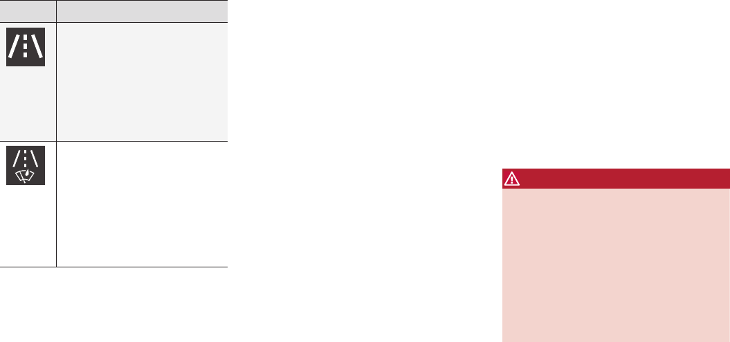
INSTRUMENTS AND CONTROLS
}}
123
Symbol Explanation
Lane keeping aid
White symbol: lane keeping aid on
and marker lines detected.
Gray symbol: lane keeping aid on
and no marker lines detected.
Yellow symbol: lane keeping aid
active
Lane keeping aid and rain sen-
sor
White symbol: lane keeping aid on
and marker lines detected. Rain
sensor on.
Gray symbol: lane keeping aid on
and no marker lines detected.
Rain sensor on.
AUS models
BCanadian models
Door/hood/tailgate/fuel filler door
reminder
If a door or the hood/tailgate/fuel filler door are
not closed properly, the information or warning
symbol will illuminate and a graphic will be dis-
played in instrument panel. Stop the vehicle in a
safe place as soon as possible and close the
door, etc.
Related information
•Instrument panel (p. 123)
•Warning symbols in the instrument panel
(p. 131)
•Door and seat belt reminders (p. 63)
Instrument panel
The instrument panel displays vehicle- and driv-
ing-related information.
The gauges, indicators, symbols and functions
displayed in the instrument panel depend on the
equipment/systems installed in the vehicle and
which functions are currently activated.
The instrument panel is available in two versions:
12" and 8".
Some of the functions listed below are optional.
WARNING
•If the instrument panel is not functioning
properly, information about e.g., brakes,
airbags or other safety-related messages
cannot be displayed and the driver cannot
be alerted to possible problems.
•If the instrument panel turns off, does not
activate when the ignition is switched on
or is completely/partially not possible to
read, do not drive the vehicle. Contact a
trained and qualified Volvo service techni-
cian.
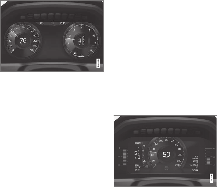
||
INSTRUMENTS AND CONTROLS
124
12" instrument panel
Left side
•Speedometer
•Trip odometer
•Odometer
•Cruise control/speed limiter information
•Road sign information
Center
•Indicator and warning symbols
•Ambient temperature sensor
•Clock
•Messages (and in certain cases also graph-
ics)
•Distance to empty tank
•Door and seat belt status
•Compass
•Media player
•Navigation system map
•Cell phone
•Voice control
Right side
•Tachometer (depending on current driving
mode)
•Fuel gauge
•Gear indicator
•Current driving mode (Comfort, Off Road,
Eco, Dynamic and Individual)
•ECO gauge (depending on current driving
mode)
•Start/Stop function's status
•Current fuel consumption
•App menu (activated using the right-side
steering wheel keypad)
8" instrument panel
Left side
•Tachometer (depending on current driving
mode)
•Current driving mode (Comfort, Off Road,
Eco, Dynamic and Individual)
•Distance to empty tank
•Gear indicator
•Ambient temperature sensor
•Indicator and warning symbols
•Fuel gauge
•ECO gauge (depending on current driving
mode)
Center
•Messages (and in certain cases also graph-
ics)
•Road sign information
•Speedometer
•Cruise control/speed limiter information
•Door and seat belt status

INSTRUMENTS AND CONTROLS
125
Right side
•Compass
•Media player
•Cell phone
•Navigation system map
•Clock
•App menu (activated using the right-side
steering wheel keypad)
•Current fuel consumption
•Odometer
•Trip odometer
•Indicator and warning symbols
•Voice control
•Coolant temperature gauge
Activating the instrument panel
The instrument panel is activated as soon as a
door is opened (i.e., ignition mode 0). After a
short period, the panel will go out if it is not used.
To reactivate it, do one of the following:
•Press the brake pedal
•Turn the start knob to START and release it
(without pressing the brake pedal). This acti-
vates ignition mode I
•Open one of the doors
Instrument panel settings
Some of the settings for the instrument panel
can be made in the App menu (see also the arti-
cle "Instrument panel app menu").
The following settings can be made in the center
display's Top view under: Settings My Car
Displays:
•Driver Display Center Area: Select what is
displayed in the background (center) of the
instrument panel. The options are: (Show no
information in the background, Show
information for current playing media or
Show navigation even if no route is
set)8. In the 12" instrument panel, the infor-
mation is shown in the center and in the 8"
instrument panel, it is shown in the field at
the upper right.
•Themes. Select a theme (appearance). The
options are: (Glass, Minimalistic,
Performance or Chrome Rings).
The system language can be changed under
Settings System Choose system
language. This change affects the language
used in all displays.
Related information
•Instrument panel App menu (p. 126)
•Warning symbols in the instrument panel
(p. 131)
•Indicator symbols in the instrument panel
(p. 121)
8The 8" instrument panel only shows guidance instructions. The 12" instrument panel only shows the map. See the navigation manual for additional information.
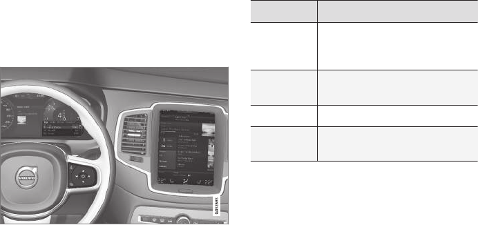
INSTRUMENTS AND CONTROLS
126
Instrument panel App menu
The App (application) menu in the instrument
panel provides quick access to commonly used
functions in certain apps.
In some cases, the App menu can be used instead of
the center display
The App menu is displayed in the instrument
panel and is controlled using the right-side steer-
ing wheel keypad. This menu makes it possible to
toggle between apps or functions in apps without
removing your hands from the steering wheel.
App menu functions
The following apps and their functions can be
controlled from the App menu:
App Functions
Trip com-
puter
Select a trip odometer, make
instrument panel display set-
tings, etc.
Media
player
Select the active source for the
media player.
Phone Call a contact from the call list.
Navigation Pause guidance, start guidance
to a recently set destination, etc.
Related information
•Instrument panel (p. 123)
•Center display overview (p. 28)
•Using the instrument panel App menu
(p. 151)
Instrument panel licenses
BSD 4-clause "Original" or "Old"
License
Copyright ©) 1982, 1986, 1990, 1991, 1993
The Regents of the University of California. All
rights reserved.
Redistribution and use in source and binary
forms, with or without modification, are permitted
provided that the following conditions are met:
1. Redistributions of source code must retain
the above copyright notice, this list of
conditions and the following disclaimer.
2. Redistributions in binary form must
reproduce the above copyright notice, this list
of conditions and the following disclaimer in
the documentation and/or other materials
provided with the distribution.
3. All advertising materials mentioning features
or use of this software must display the
following acknowledgment: This product
includes software developed by the
University of California, Berkeley and its
contributors.
4. Neither the name of the University nor the
names of its contributors may be used to
endorse or promote products derived from
this software without specific prior written
permission.
THIS SOFTWARE IS PROVIDED BY THE
REGENTS AND CONTRIBUTORS ``AS IS'' AND
ANY EXPRESS OR IMPLIED WARRANTIES,
INSTRUMENTS AND CONTROLS
}}
127
INCLUDING, BUT NOT LIMITED TO, THE
IMPLIED WARRANTIES OF MERCHANTABILITY
AND FITNESS FOR A PARTICULAR PURPOSE
ARE DISCLAIMED. IN NO EVENT SHALL THE
REGENTS OR CONTRIBUTORS BE LIABLE
FOR ANY DIRECT, INDIRECT, INCIDENTAL,
SPECIAL, EXEMPLARY, OR CONSEQUENTIAL
DAMAGES (INCLUDING, BUT NOT LIMITED TO,
PROCUREMENT OF SUBSTITUTE GOODS OR
SERVICES; LOSS OF USE, DATA, OR PROFITS;
OR BUSINESS INTERRUPTION) HOWEVER
CAUSED AND ON ANY THEORY OF LIABILITY,
WHETHER IN CONTRACT, STRICT LIABILITY,
OR TORT (INCLUDING NEGLIGENCE OR
OTHERWISE) ARISING IN ANY WAY OUT OF
THE USE OF THIS SOFTWARE, EVEN IF
ADVISED OF THE POSSIBILITY OF SUCH
DAMAGE.
BSD 3-clause "New" or "Revised"
License
Copyright (c) 2011-2014, Yann Collet.
Redistribution and use in source and binary
forms, with or without modification, are permitted
provided that the following conditions are met:
1. Redistributions of source code must retain
the above copyright notice, this list of
conditions and the following disclaimer.
2. Redistributions in binary form must
reproduce the above copyright notice, this list
of conditions and the following disclaimer in
the documentation and/or other materials
provided with the distribution.
3. Neither the name of the organisation nor the
names of its contributors may be used to
endorse or promote products derive from this
software without specific prior written
permission.
THIS SOFTWARE IS PROVIDED BY THE
COPYRIGHT HOLDERS AND CONTRIBUTORS
"AS IS" AND ANY EXPRESS OR IMPLIED
WARRANTIES, INCLUDING, BUT NOT LIMITED
TO, THE IMPLIED WARRANTIES OF
MERCHANTABILITY AND FITNESS FOR A
PARTICULAR PURPOSE ARE DISCLAIMED. IN
NO EVENT SHALL THE COPYRIGHT HOLDER
OR CONTRIBUTORS BE LIABLE FOR ANY
DIRECT, INDIRECT, INCIDENTAL, SPECIAL,
EXEMPLARY, OR CONSEQUENTIAL DAMAGES
(INCLUDING, BUT NOT LIMITED TO,
PROCUREMENT OF SUBSTITUTE GOODS OR
SERVICES; LOSS OF USE, DATA, OR PROFITS;
OR BUSINESS INTERRUPTION) HOWEVER
CAUSED AND ON ANY THEORY OF LIABILITY,
WHETHER IN CONTRACT, STRICT LIABILITY,
OR TORT (INCLUDING NEGLIGENCE OR
OTHERWISE) ARISING IN ANY WAY OUT OF
THE USE OF THIS SOFTWARE, EVEN IF
ADVISED OF THE POSSIBILITY OF SUCH
DAMAGE.
BSD 2-clause “Simplified” license
Copyright ©) <YEAR>, <OWNER> All rights
reserved.
Redistribution and use in source and binary
forms, with or without modification, are permitted
provided that the following conditions are met:
1. Redistributions of source code must retain
the above copyright notice, this list of
conditions and the following disclaimer.
2. Redistributions in binary form must
reproduce the above copyright notice, this list
of conditions and the following disclaimer in
the documentation and/or other materials
provided with the distribution.
THIS SOFTWARE IS PROVIDED BY THE
COPYRIGHT HOLDERS AND CONTRIBUTORS
"AS IS" AND ANY EXPRESS OR IMPLIED
WARRANTIES, INCLUDING, BUT NOT LIMITED
TO, THE IMPLIED WARRANTIES OF
MERCHANTABILITY AND FITNESS FOR A
PARTICULAR PURPOSE ARE DISCLAIMED. IN
NO EVENT SHALL THE COPYRIGHT OWNER
OR CONTRIBUTORS BE LIABLE FOR ANY
DIRECT, INDIRECT, INCIDENTAL, SPECIAL,
EXEMPLARY, OR CONSEQUENTIAL DAMAGES
(INCLUDING, BUT NOT LIMITED TO,
PROCUREMENT OF SUBSTITUTE GOODS OR
SERVICES; LOSS OF USE, DATA, OR PROFITS;
OR BUSINESS INTERRUPTION) HOWEVER
CAUSED AND ON ANY THEORY OF LIABILITY,
WHETHER IN CONTRACT, STRICT LIABILITY,
OR TORT (INCLUDING NEGLIGENCE OR
OTHERWISE) ARISING IN ANY WAY OUT OF
THE USE OF THIS SOFTWARE, EVEN IF
||
INSTRUMENTS AND CONTROLS
128
ADVISED OF THE POSSIBILITY OF SUCH
DAMAGE.
The views and conclusions contained in the
software and documentation are those of the
authors and should not be interpreted as
representing official policies, either expressed or
implied, of the FreeBSD Project.
FreeType Project License
1. 1 Copyright 1996-1999 by David Turner,
Robert Wilhelm, and Werner Lemberg
Introduction The FreeType Project is
distributed in several archive packages; some
of them may contain, in addition to the
FreeType font engine, various tools and
contributions which rely on, or relate to, the
FreeType Project. This license applies to all
files found in such packages, and which do
not fall under their own explicit license. The
license affects thus the FreeType font
engine, the test programs, documentation
and makefiles, at the very least. This license
was inspired by the BSD, Artistic, and IJG
(Independent JPEG Group) licenses, which
all encourage inclusion and use of free
software in commercial and freeware
products alike. As a consequence, its main
points are that: o We don't promise that this
software works. However, we are be
interested in any kind of bug reports. (`as is'
distribution) o You can use this software for
whatever you want, in parts or full form,
without having to pay us. (`royalty-free'
usage) o You may not pretend that you wrote
this software. If you use it, or only parts of it,
in a program, you must acknowledge
somewhere in your documentation that
you've used the FreeType code. (`credits')
We specifically permit and encourage the
inclusion of this software, with or without
modifications, in commercial products,
provided that all warranty or liability claims
are assumed by the product vendor. Legal
Terms 0. Definitions Throughout this license,
the terms `package', `FreeType Project', and
`FreeType archive' refer to the set of files
originally distributed by the authors (David
Turner, Robert Wilhelm, and Werner
Lemberg) as the `FreeType project', be they
named as alpha, beta or final release. `You'
refers to the licensee, or person using the
project, where `using' is a generic term
including compiling the project's source code
as well as linking it to form a `program' or
`executable'. This program is referred to as `a
program using the FreeType engine'. This
license applies to all files distributed in the
original FreeType archive, including all source
code, binaries and documentation, unless
otherwise stated in the file in its original,
unmodified form as distributed in the original
archive. If you are unsure whether or not a
particular file is covered by this license, you
must contact us to verify this. The FreeType
project is copyright (C) 1996-1999 by David
Turner, Robert Wilhelm, and Werner
Lemberg. All rights reserved except as
specified below. 1. No Warranty THE
FREETYPE ARCHIVE IS PROVIDED `AS IS'
WITHOUT WARRANTY OF ANY KIND,
EITHER EXPRESSED OR IMPLIED,
INCLUDING, BUT NOT LIMITED TO,
WARRANTIES OF MERCHANTABILITY AND
FITNESS FOR A PARTICULAR PURPOSE.
IN NO EVENT WILL ANY OF THE
AUTHORS OR COPYRIGHT HOLDERS BE
LIABLE FOR ANY DAMAGES CAUSED BY
THE USE OR THE INABILITY TO USE, OF
THE FREETYPE PROJECT. As you have not
signed this license, you are not required to
accept it. However, as the FreeType project
is copyrighted material, only this license, or
another one contracted with the authors,
grants you the right to use, distribute, and
modify it. Therefore, by using, distributing, or
modifying the FreeType project, you indicate
that you understand and accept all the terms
of this license.
2. Redistribution Redistribution and use in
source and binary forms, with or without
modification, are permitted provided that the
following conditions are met: o Redistribution
of source code must retain this license file
(`licence.txt') unaltered; any additions,
deletions or changes to the original files
must be clearly indicated in accompanying
documentation. The copyright notices of the
unaltered, original files must be preserved in
all copies of source files. o Redistribution in
binary form must provide a disclaimer that
states that the software is based in part of
the work of the FreeType Team, in the
distribution documentation. We also
INSTRUMENTS AND CONTROLS
}}
129
encourage you to put an URL to the
FreeType web page in your documentation,
though this isn't mandatory. These conditions
apply to any software derived from or based
on the FreeType code, not just the
unmodified files. If you use our work, you
must acknowledge us. However, no fee need
be paid to us.
3. Advertising The names of FreeType's authors
and contributors may not be used to endorse
or promote products derived from this
software without specific prior written
permission. We suggest, but do not require,
that you use one or more of the following
phrases to refer to this software in your
documentation or advertising materials:
`FreeType Project', `FreeType Engine',
`FreeType library', or `FreeType Distribution'.
4. Contacts There are two mailing lists related
to FreeType: o freetype@freetype.org
Discusses general use and applications of
FreeType, as well as future and wanted
additions to the library and distribution. If you
are looking for support, start in this list if you
haven't found anything to help you in the
documentation. o devel@freetype.org
Discusses bugs, as well as engine internals,
design issues, specific licenses, porting, etc.
o http://www.freetype.org Holds the current
FreeType web page, which will allow you to
download our latest development version and
read online documentation. You can also
contact us individually at: David Turner
<david.turner@freetype.org> Robert Wilhelm
<robert.wilhelm@freetype.org> Werner
Lemberg <werner.lemberg@freetype.org>
Libpng License
This copy of the libpng notices is provided for
your convenience. In case of any discrepancy
between this copy and the notices in the file
png.h that is included in the libpng distribution,
the latter shall prevail.
COPYRIGHT NOTICE, DISCLAIMER, and
LICENSE:
If you modify libpng you may insert additional
notices immediately following this sentence.
libpng versions 1.0.7, July 1, 2000, through
1.0.13, April 15, 2002, are Copyright (c)
2000-2002 Glenn Randers-Pehrson and are
distributed according to the same disclaimer and
license as libpng-1.0.6 with the following
individuals added to the list of Contributing
Authors
Simon-Pierre Cadieux
Eric S. Raymond
Gilles Vollant
and with the following additions to the disclaimer:
There is no warranty against interference with
your enjoyment of the library or against
infringement. There is no warranty that our efforts
or the library will fulfill any of your particular
purposes or needs. This library is provided with all
faults, and the entire risk of satisfactory quality,
performance, accuracy, and effort is with the user.
libpng versions 0.97, January 1998, through
1.0.6, March 20, 2000, are Copyright (c) 1998,
1999 Glenn Randers-Pehrson, and are
distributed according to the same disclaimer and
license as libpng-0.96, with the following
individuals added to the list of Contributing
Authors:
Tom Lane
Glenn Randers-Pehrson
Willem van Schaik
libpng versions 0.89, June 1996, through 0.96,
May 1997, are Copyright (c) 1996, 1997
Andreas Dilger Distributed according to the same
disclaimer and license as libpng-0.88, with the
following individuals added to the list of
Contributing Authors:
John Bowler
Kevin Bracey
Sam Bushell
Magnus Holmgren
Greg Roelofs
Tom Tanner
libpng versions 0.5, May 1995, through 0.88,
January 1996, are Copyright (c) 1995, 1996 Guy
Eric Schalnat, Group 42, Inc.
||
INSTRUMENTS AND CONTROLS
130
For the purposes of this copyright and license,
"Contributing Authors" is defined as the following
set of individuals:
Andreas Dilger
Dave Martindale
Guy Eric Schalnat
Paul Schmidt
Tim Wegner
The PNG Reference Library is supplied "AS IS".
The Contributing Authors and Group 42, Inc.
disclaim all warranties, expressed or implied,
including, without limitation, the warranties of
merchantability and of fitness for any purpose.
The Contributing Authors and Group 42, Inc.
assume no liability for direct, indirect, incidental,
special, exemplary, or consequential damages,
which may result from the use of the PNG
Reference Library, even if advised of the
possibility of such damage.
Permission is hereby granted to use, copy,
modify, and distribute this source code, or
portions hereof, for any purpose, without fee,
subject to the following restrictions:
1. The origin of this source code must not be
misrepresented.
2. Altered versions must be plainly marked as
such and must not be misrepresented as
being the original source.
3. This Copyright notice may not be removed or
altered from any source or altered source
distribution.
The Contributing Authors and Group 42, Inc.
specifically permit, without fee, and encourage
the use of this source code as a component to
supporting the PNG file format in commercial
products. If you use this source code in a product,
acknowledgment is not required but would be
appreciated.
A "png_get_copyright" function is available, for
convenient use in "about" boxes and the like:
printf("%s",png_get_copyright(NULL));
Also, the PNG logo (in PNG format, of course) is
supplied in the files "pngbar.png" and
"pngbar.jpg (88x31) and "pngnow.png" (98x31).
Libpng is OSI Certified Open Source Software.
OSI Certified Open Source is a certification mark
of the Open Source Initiative.
Glenn Randers-Pehrson randeg@alum.rpi.edu
April 15, 2002
MIT License
Copyright (c) <year> <copyright holders>
Permission is hereby granted, free of charge, to
any person obtaining a copy of this software and
associated documentation files (the "Software"),
to deal in the Software without restriction,
including without limitation the rights to use,
copy, modify, merge, publish, distribute,
sublicense, and/or sell copies of the Software,
and to permit persons to whom the Software is
furnished to do so, subject to the following
conditions:
The above copyright notice and this permission
notice shall be included in all copies or
substantial portions of the Software.
THE SOFTWARE IS PROVIDED "AS IS",
WITHOUT WARRANTY OF ANY KIND,
EXPRESS OR IMPLIED, INCLUDING BUT NOT
LIMITED TO THE WARRANTIES OF
MERCHANTABILITY, FITNESS FOR A
PARTICULAR PURPOSE AND
NONINFRINGEMENT. IN NO EVENT SHALL
THE AUTHORS OR COPYRIGHT HOLDERS BE
LIABLE FOR ANY CLAIM, DAMAGES OR
OTHER LIABILITY, WHETHER IN AN ACTION
OF CONTRACT, TORT OR OTHERWISE,
ARISING FROM, OUT OF OR IN CONNECTION
WITH THE SOFTWARE OR THE USE OR
OTHER DEALINGS IN THE SOFTWARE.
zlib License
The zlib/libpng License Copyright (c) <year>
<copyright holders>
This software is provided 'as-is', without any
express or implied warranty. In no event will the
authors be held liable for any damages arising
from the use of this software.
Permission is granted to anyone to use this
software for any purpose, including commercial
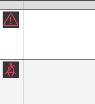
INSTRUMENTS AND CONTROLS
}}
131
applications, and to alter it and redistribute it
freely, subject to the following restrictions:
1. The origin of this software must not be
misrepresented; you must not claim that you
wrote the original software. If you use this
software in a product, an acknowledgment in
the product documentation would be
appreciated but is not required.
2. Altered source versions must be plainly
marked as such, and must not be
misrepresented as being the original
software.
3. This notice may not be removed or altered
from any source distribution.
SGI Free Software B License Version
2.0.
SGI FREE SOFTWARE LICENSE B (Version 2.0,
Sept. 18, 2008)
Copyright (C) [dates of first publication] Silicon
Graphics, Inc. All Rights Reserved. Permission is
hereby granted, free of charge, to any person
obtaining a copy of this software and associated
documentation files (the "Software"), to deal in
the Software without restriction, including without
limitation the rights to use, copy, modify, merge,
publish, distribute, sublicense, and/or sell copies
of the Software, and to permit persons to whom
the Software is furnished to do so, subject to the
following conditions: The above copyright notice
including the dates of first publication and either
this permission notice or a reference to http://
oss.sgi.com/projects/FreeB/ shall be included in
all copies or substantial portions of the Software.
THE SOFTWARE IS PROVIDED "AS IS",
WITHOUT WARRANTY OF ANY KIND,
EXPRESS OR IMPLIED, INCLUDING BUT NOT
LIMITED TO THE WARRANTIES OF
MERCHANTABILITY, FITNESS FOR A
PARTICULAR PURPOSE AND
NONINFRINGEMENT. IN NO EVENT SHALL
SILICON GRAPHICS, INC. BE LIABLE FOR ANY
CLAIM, DAMAGES OR OTHER LIABILITY,
WHETHER IN AN ACTION OF CONTRACT,
TORT OR OTHERWISE, ARISING FROM, OUT
OF OR IN CONNECTION WITH THE SOFTWARE
OR THE USE OR OTHER DEALINGS IN THE
SOFTWARE.
Except as contained in this notice, the name of
Silicon Graphics, Inc. shall not be used in
advertising or otherwise to promote the sale, use
or other dealings in this Software without prior
written authorization from Silicon Graphics, Inc.
Related information
•Instrument panel (p. 123)
Warning symbols in the instrument
panel
The warning symbols alert the driver that an
important function is activated or that a serious
fault has occurred.
Symbol Meaning
Warning
The red warning symbol alerts the
driver that an important function is
activated or that a serious fault
has occurred that may affect the
vehicle's drivability. The warning
symbol can also illuminate in com-
bination with other symbols.
Seat belt reminder
This symbol will flash for approxi-
mately 6 seconds if the driver or
front seat passenger has not fas-
tened his or her seat belt or if any-
one in the rear seat has unbuck-
led a seat belt.
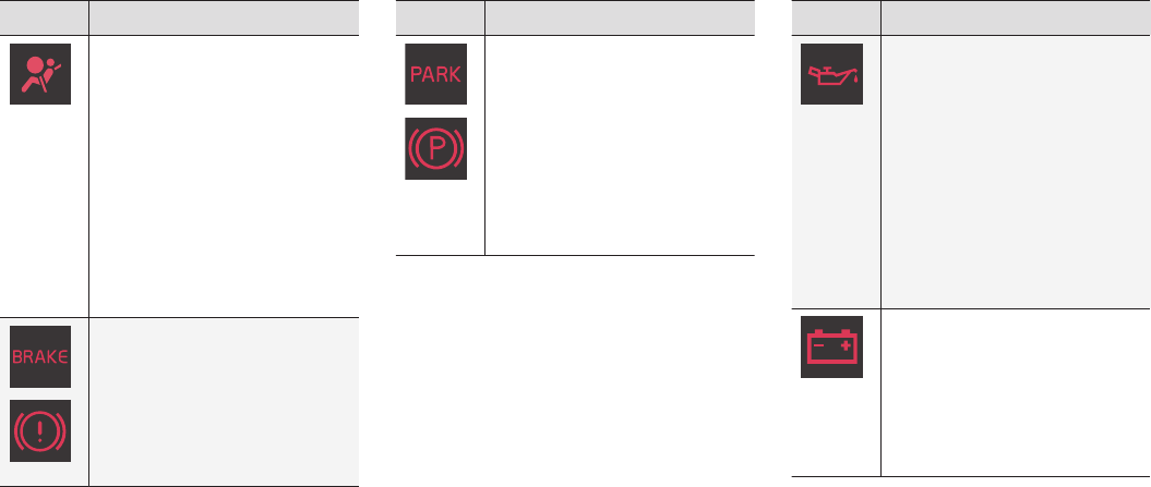
||
INSTRUMENTS AND CONTROLS
132
Symbol Meaning
Airbags
Stop the vehicle in a safe place
and do not continue driving.
If this light comes on while the
vehicle is being driven, or remains
on after the vehicle has been
started, the airbag system's diag-
nostic functions have detected a
fault. Have the system(s) inspec-
ted by a trained and qualified
Volvo service technician as soon
as possible.
A
B
Brake system
If this symbol illuminates, the
brake fluid level may be too low.
Stop the vehicle in a safe place
and check the level in the brake
fluid reservoir. See also the warn-
ing following this table.
Symbol Meaning
A
B
Parking brake
This symbol flashes while the
parking brake is being applied and
then glows steadily when the
parking brake has been set.
If the symbol flashes in any other
situation, this indicates a fault. See
the text message in the instru-
ment panel.
Symbol Meaning
Oil pressure
If the symbol illuminates during
driving, stop the vehicle, the
engine oil level is too low. Stop the
engine immediately and check the
engine oil level. Add oil if neces-
sary. If the oil level is normal and
the symbol remains illuminated,
have the vehicle towed to the
nearest authorized Volvo work-
shop or trained and qualified Volvo
service technician.
Generator not charging
This symbol illuminates during
driving if a fault has occurred in
the electrical system. Contact an
authorized Volvo workshop or
trained and qualified Volvo service
technician.
AUS models
BCanadian models
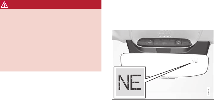
INSTRUMENTS AND CONTROLS
133
WARNING
•If the fluid level is below the MIN mark in
the brake fluid reservoir or if a warning
message is displayed in the text window:
DO NOT DRIVE. Have the vehicle towed
to a trained and qualified Volvo service
technician and have the brake system
inspected.
•If the BRAKE and ABS symbols illumi-
nate at the same time, there is a risk of
reduced vehicle stability.
Door/hood/tailgate/fuel filler door
reminder
It a door, tailgate, the hood or the fuel filler door
are not closed properly, the information or warn-
ing symbol will illuminate and a graphic will be
displayed in the instrument panel.
Related information
•Instrument panel (p. 123)
•Indicator symbols in the instrument panel
(p. 121)
Compass
The rear-view mirror has an integrated compass
that shows the direction in which the vehicle is
traveling.
Rearview mirror with compass
Eight different directions are shown with the
abbreviations: N (north) NE (northeast) E (east),
SE (southeast) S (south), SW (southwest) W
(west) NW (northwest)
Switching the compass on/off
The compass is displayed automatically when the
vehicle is started or in ignition mode II.
To switch the compass on/off:
–Use a pen, paperclip or similar object and
press in the button on the underside of the
mirror.
Related information
•Calibrating the compass (p. 134)
•Ignition modes (p. 360)
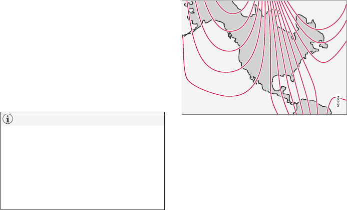
INSTRUMENTS AND CONTROLS
* Option/accessory, for more information, see Introduction.
134
Calibrating the compass
North America is divided into 15 magnetic zones
and the compass will need to be calibrated if the
vehicle is driven from one zone to another.
To calibrate the compass:
1. Stop the vehicle in a large open area, safely
out of traffic and away from steel structures
and high-tension electrical wires.
2. Start the vehicle.
NOTE
•For best calibration results, switch off all
electrical equipment in the vehicle (climate
system, windshield wipers, audio system,
etc.) and make sure that all doors are
closed.
•Calibration may not succeed or be incor-
rect if the vehicle's electrical equipment is
not switched off.
3. Using a pen, paperclip or similar object, press
and hold the button on the underside of mir-
ror for approx. 3 seconds until the number of
the current magnetic zone is displayed.
15
14
13
12
11
9
8
7
6
5
4
3
2
1
10
Magnetic zones
4. Press the button on the underside of mirror
repeatedly until the desired magnetic zone
(1–15) is displayed (see the map of mag-
netic zones).
5. Wait until C is again displayed in the mirror
or hold the button on the underside of mirror
for approx. 6 seconds until C is displayed in
the mirror.
6. Drive slowly in a circle at a speed of no more
than 6 mph (10 km/h) until a direction is dis-
played. This indicates that calibration is com-
plete. Drive around in a circle an additional
two times to fine-tune the calibration.
7. Vehicles with an electrically heated wind-
shield:* if C is displayed when the heating
function is activated, perform step 6 with the
heating function on.
8. Repeat the calibration procedure if neces-
sary.
Related information
•Defrosting windows and mirrors (p. 186)
•Compass (p. 133)
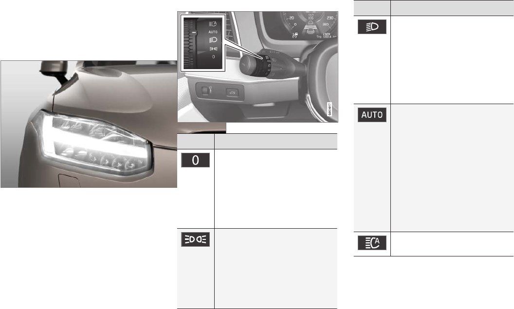
INSTRUMENTS AND CONTROLS
}}
* Option/accessory, for more information, see Introduction. 135
Lighting panel and controls
The lighting controls on the left-side steering
wheel lever can be used to activate the vehicle's
exterior lighting. Instrument lighting brightness
can be adjusted on the lighting panel.
Ring on the steering wheel lever
Position Result
With the ignition in mode II or if
the engine is running:
•In the US: the Daytime Run-
ning Lights (DRL) will be off
•In Canada: the Daytime Run-
ning Lights will be on
•High beam flash can be used
With the ignition in mode II or if
the engine is running:A
•In the US: the Daytime Run-
ning Lights will be off
•In Canada: the Daytime Run-
ning Lights will be on
•High beam flash can be used
Position Result
With the ignition in mode II or if
the engine is running:
•The Daytime Running Lights
will be off
•The low beam headlights will
be on
•High Beams/High Beam flash
can be used
With the ignition in mode II or if
the engine is running:
•The Daytime Running Lights
will be onB (the low beam
headlights will automatically
switch on in dark conditions or
if the rear fog lights are on
•Tunnel detection* will be acti-
vated
•Active High Beams (AHB) can
be activated
•High beam flash can be used
Active High Beams On/Off
AThe parking lights will be on in this position, even if the ignition
is switched off. In dark conditions, the rear parking lights illumi-
nate automatically when the tailgate is open, regardless of the
control's position or ignition mode.
BUS models only: The use of Daytime Running Lights can be
activated/deactivated in the center display's Settings menu.
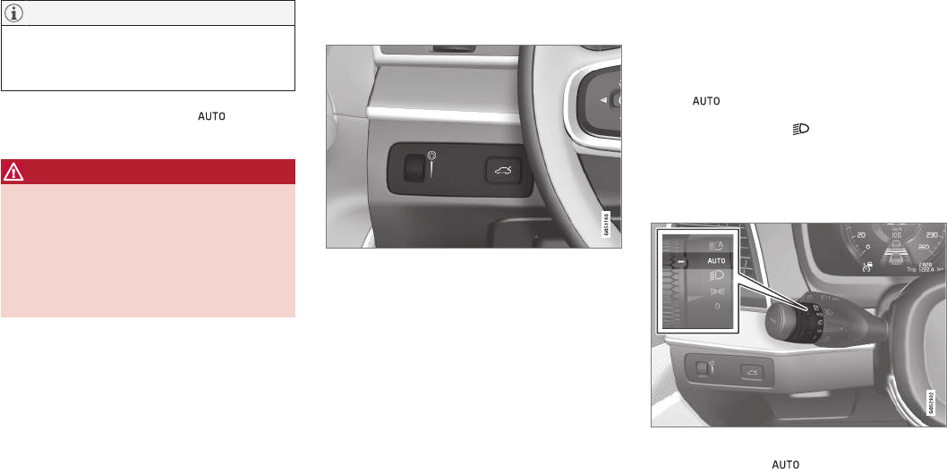
||
INSTRUMENTS AND CONTROLS
136
NOTE
The use of Daytime Running Lights is recom-
mended in the United States and is manda-
tory in Canada.
Volvo recommends using the position
whenever possible.
WARNING
•Daytime Running Lights are a driving aid
designed to help make the vehicle visible
to other roads users.
•The driver is always responsible for
adapting the use of Daytime Running
Lights/headlights according to ambient
lighting and weather conditions.
Lighting panel
Instrument lighting
Thumb wheel (to the left) for adjusting display bright-
ness
Illumination of the display and instrument lights
will vary, depending on ignition mode.
The display lighting is automatically subdued in
darkness and the sensitivity is set with the thumb
wheel.
Related information
•Daytime Running Lights (DRL) (p. 137)
•High and low beam headlights (p. 137)
Low beam headlights
In dark ambient lighting conditions, the low
beams will be activated automatically when the
engine is started or the ignition is in mode II and
the left-side steering wheel lever's ring is turned
to the position.
If the ring is turned to , the low beams will
be activated automatically when the engine is
started or the ignition is in mode II, regardless of
the ambient lighting conditions.
Low beams
Left-side steering wheel lever ring
With the ring in the position, the low
beams will also be activated if the windshield
wipers or rear fog lights are being used.
Related information
•Daytime Running Lights (DRL) (p. 137)
•Ignition modes (p. 360)
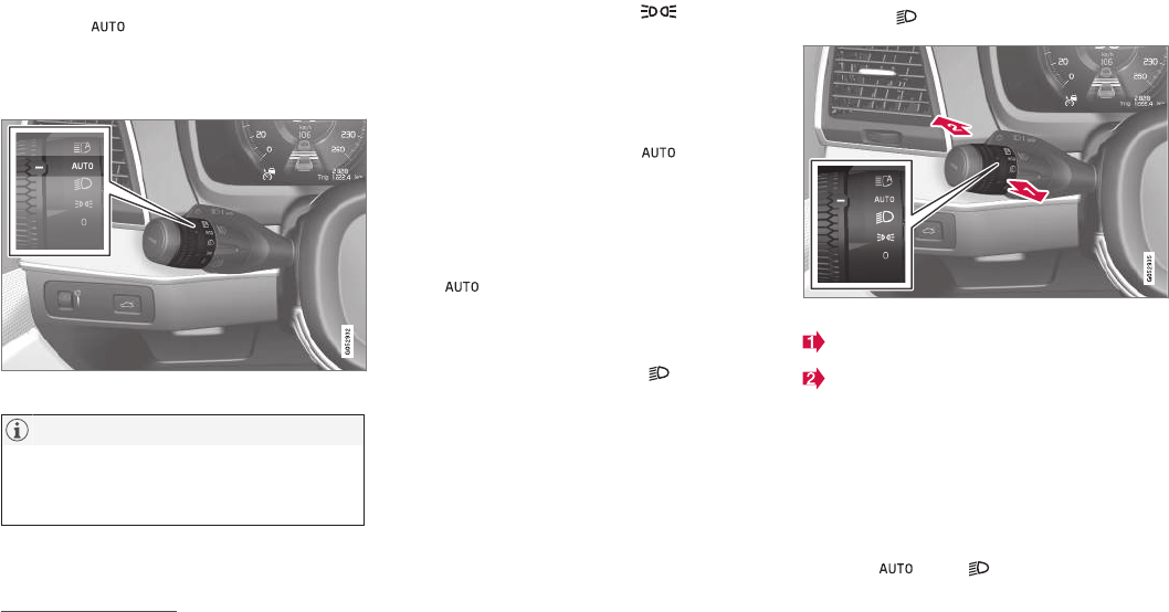
INSTRUMENTS AND CONTROLS
}}
137
Daytime Running Lights (DRL)
The car monitors ambient lighting conditions.
With the ring on the left-side steering wheel
lever in the position and the ignition in
mode II (or the engine running), the lights toggle
automatically between DRL and low beam head-
lights.
Ring in the AUTO position.
NOTE
The use of Daytime Running Lights is recom-
mended in the United States and is manda-
tory in Canada.
With the headlight ring in the 0 position:
•In the US: DRL will be off
•In Canada: DRL will be on
With the headlight ring in the 9 position
and the ignition in mode II or if the engine is
running:
•In the US: DRL will be off
•In Canada: DRL will be on
With the headlight ring in the position:
•DRL will be on (the low beam headlights will
automatically switch on in dark conditions)
US models only: DRL can be deactivated in the
center display's Settings view.
With selected, a tunnel detection function
activates the low beams when the vehicle enters
a tunnel.
With the headlight ring in the position:
•DRL will be off and the low beam headlights
will be on
High and low beam headlights
When the engine is started, the low beams are
activated automatically if the headlight control is
in position .
Steering wheel lever and ring
High beam flash
Toggle between high and low beams
High beam flash
Pull the lever slightly toward the steering wheel.
The high beams illuminate until the lever is
released.
Continuous high beams
Continuous high beams are available if the ring is
turned to 10 or . Toggle to high
9The parking lights will be on in this position, even if the ignition is switched off.
10 When the low beams are on.
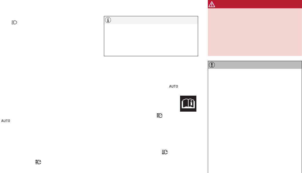
||
INSTRUMENTS AND CONTROLS
138
beams by moving the lever forward. Return to low
beams by moving the lever toward the steering
wheel.
The symbol will illuminate in the instrument
panel when the high beams are on.
Active high beams
The active high beam system uses a camera at
the upper edge of the windshield to detect the
headlights of oncoming vehicles or the taillights
of a vehicle directly ahead. When this happens,
the headlights will automatically switch from high
beams to low beams.
When the camera no longer detects the head-
lights/taillights of other vehicles, your headlights
will switch back to high beams after several sec-
onds.
Operation
Activate/deactivate this function by turning the
ring on the left-side steering wheel lever to
.
If the ring is not in this position, toggling between
high and low beams must be done manually.
If the ring is turned to another position while the
high beams are on, the headlights will automati-
cally switch to low beams.
A white symbol ( ) in the instrument panel
indicates that the function has been activated.
When the high beams are on, the symbol will
change to blue.
NOTE
•Keep the windshield in front of the cam-
era free of ice, snow, dirt, etc.
•Do not mount or in any way attach any-
thing on the windshield that could
obstruct the camera.
If a message is displayed in the instrument panel
saying that active high beams are temporarily
unavailable, switching between high and low
beams will have to be done manually. However,
the light switch can remain in the position.
The same applies if a message saying that the
windshield sensors are blocked and the
symbol are displayed. The symbol will go
out if this happens.
Automatic high beams may be temporarily
unavailable (e.g., in heavy fog or rain). When the
system becomes active again or if the sensors in
the windshield are no longer obscured, the mes-
sages will disappear and the symbol will
illuminate.
WARNING
•Automatic high beams are a driving aid
designed to help provide the best possi-
ble headlight illumination in good driving
conditions.
•The driver is always responsible for man-
ually toggling between high and low
beams when this is required by traffic or
weather conditions.
CAUTION
In the following situations, it may be neces-
sary to switch between high and low beams
manually:
•In heavy fog or rain
•In blowing snow or slush
•In bright moonlight
•In freezing rain
•In areas with dim street lighting
•When oncoming vehicles have dim front
lighting
•If there are pedestrians on or near the
road
•If there are reflective objects, such as
signs, near the road
•When oncoming vehicles' lights are
obscured by e.g., fences, bushes, etc.
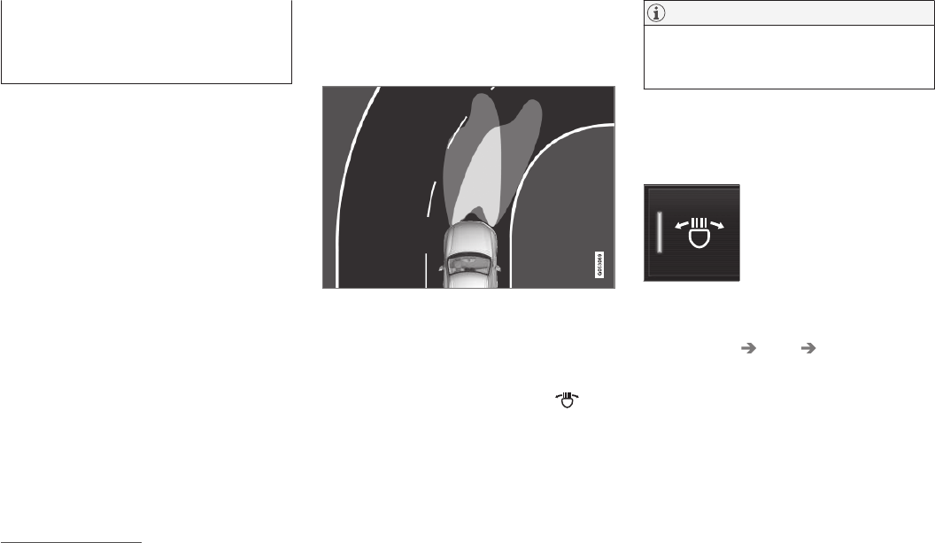
INSTRUMENTS AND CONTROLS
* Option/accessory, for more information, see Introduction. 139
•When there are vehicles on connecting
roads
•At the top of hills or in dips in the road
•In sharp curves
Auxiliary lights*
If the vehicle is equipped with auxiliary lights, the
driver can use the center display to activate/
deactivate them or decide if they will go on/off
along with the high beams11.
Related information
•City Safety™ troubleshooting (p. 285)
•Lighting panel and controls (p. 135)
Active Bending Lights*
Active Bending Lights (ABL) are designed to
help light up a curve according to movements of
the steering wheel.
Headlight pattern with the Active Bending Light function
deactivated (left) and activated (right)
ABL is activated automatically12 when the engine
is started and can be deactivated in the center
display.
If a fault is detected in the system, the
symbol in the instrument panel will illuminate. A
text message will be displayed and an additional
symbol will also illuminate.
NOTE
This function is only active in twilight or dark
conditions, and only when the vehicle is in
motion.
Deactivating/activating the function
ABL can be deactivated/activated in two ways in
the center display:
Via Function view
Tap the Active Bending
Lights button.
Via settings
1. Tap Settings in Top view.
2. Tap My Car Lights Exterior Lights.
3. Deselect/select Active Bending Lights.
Related information
•Settings view (p. 107)
11 These lights must be connected to the vehicle's electrical system by a trained and qualified Volvo service technician.
12 The factory default setting is on.
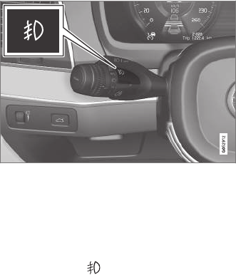
INSTRUMENTS AND CONTROLS
* Option/accessory, for more information, see Introduction.
140
Front fog lights*
Front fog light button
The front fog lights can be used in combination
with the high/low beam headlights or the parking
lights. Both fog lights also illuminate when the
vehicle is backing up.
Press the button to turn the fog lights on/off. The
indicator symbol in the instrument panel
illuminates when the front fog lights are on.
Corner illumination
The front fog lights include corner illumination,
which temporarily provides extra light to the front
left or right of the vehicle (depending on which
way the vehicle is turned) when making a sharp
turn at low speeds (for example, when turning
into a parking space) or when the turn signals are
used.
This function is activated when the high or low
beam headlights are used and the vehicle's
speed is under approx. 20 mph (30 km/h).
Related information
•Low beam headlights (p. 136)
Brake lights
The brake lights illuminate automatically when
the brakes are applied.
In addition to illuminating when the brake pedal is
depressed, the brake lights also illuminate when
one of the driver support systems (e.g., adaptive
cruise control, City Safety or collision warning)
slow the vehicle.
Related information
•Adaptive Cruise Control (ACC)* (p. 256)
•City Safety™ (p. 277)
•Emergency brake lights (p. 340)
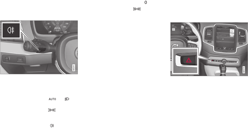
INSTRUMENTS AND CONTROLS
141
Rear fog lights
The rear fog lights are considerably brighter than
the normal taillights and should be used only
when conditions such as fog, rain, snow, smoke
or dust reduce visibility for other vehicles to less
than 500 ft. (150 meters).
Rear fog light button
The rear fog lights can only be used when:
•the ignition is in mode II or if the engine is
running and the left-side steering wheel lev-
er's thumb wheel is in the or
position
•the thumb wheel is in the position and
the front fog lights are on
Press the button to turn the fog lights on/off. The
rear fog light indicator symbol in the
instrument panel illuminates when the rear fog
lights are switched on.
The rear fog lights switch off automatically when:
•the start knob is turned to STOP or when
the light switch is turned to the
•the thumb wheel is in the position and
the front fog lights are turned off
Related information
•Lighting panel and controls (p. 135)
Hazard warning flashers
The hazard warning flashers should be used to
indicate that the vehicle has become a traffic
hazard.
When the function is activated, both turn signal
indicators in the instrument panel will flash.
Hazard warning flasher button
Press the button to activate the flashers. Press
the button again to turn off the flashers.
Regulations regarding the use of the hazard
warning flashers may vary, depending on where
you live.
Related information
•Using turn signals (p. 145)
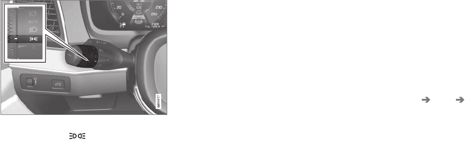
INSTRUMENTS AND CONTROLS
* Option/accessory, for more information, see Introduction.
142
Parking lights
Turn the parking lights on by turning the ring on
the left-side steering wheel lever.
Lighting ring in the parking light position
Turn the ring to the position (the license
plate lighting comes on at the same time).
Canadian models: If the ignition is in position II
or the engine is running, the daytime running
lights will also be on.
With the ring in this position, the parking lights
will remain on even when the ignition is switched
off, however, the rear parking lights will not be on
if the ignition is in model 0.
In dark ambient lighting conditions, the rear park-
ing lights also illuminate when the tailgate is
opened to alert anyone traveling behind your
vehicle. This happens regardless of the position
that the headlight control is in or which mode the
ignition is in.
Related information
•Lighting panel and controls (p. 135)
Approach lighting
Approach lighting activates the parking lights,
outer door handle lights*, license plate lighting,
courtesy lighting and footwell lighting when you
approach the vehicle.
This function is activated by unlocking the car.
The time interval for this lighting can be set on
the center display.
The function can be deactivated/activated in the
center display:
1. Tap Settings in Top view.
2. Tap My Car Lights Exterior Lights.
3. Deselect/select Welcome Light.
Related information
•Settings view (p. 107)
•Home safe lighting (p. 143)
•Remote key (p. 225)
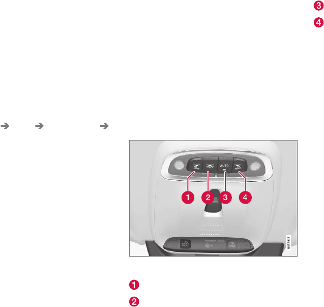
INSTRUMENTS AND CONTROLS
}}
* Option/accessory, for more information, see Introduction. 143
Home safe lighting
The home safe lighting function illuminates the
area in front of the vehicle in dark conditions.
This function turns on the headlights, parking
lights, outer door handle lights*, license plate
lights, front ceiling lighting and footwell lighting
for a set amount of time.
The length of time that these lights remain illumi-
nated can be set in the center display:
1. Tap Settings in Top view.
2. Tap My Car Lights Exterior Lights
Home Safety Lights.
3. Select Off, 30 sec, 60 sec or 90 sec.
To activate home safe lighting:
1. Switch off the ignition (mode 0).
2. Push the turn signal lever as far as possible
towards the dashboard and release it.
3. Exit the vehicle and lock the doors.
Related information
•Using the center display (p. 45)
•Settings view (p. 107)
Passenger compartment lighting
The passenger compartment lighting is con-
trolled using the buttons in the ceiling above the
front and rear seats.
All passenger compartment lighting can be
turned on and off manually within 30 minutes
after:
•the vehicle is unlocked but the engine has
not been started
•the engine is switched off and the ignition is
in mode 0.
Front interior lighting
Controls in the ceiling console for front reading lights
and courtesy lighting
Driver's side reading light
Courtesy lighting
Courtesy lighting (AUTO) switch
Passenger's side reading light
Front reading lights
Turn the reading lights on or off by pressing the
respective buttons briefly. Adjust the brightness
by pressing and holding the button.
Courtesy lighting
Turn the footwell and overhead courtesy lighting
on or off by pressing the button briefly.
Courtesy lighting switch
Activate the automatic function by briefly press-
ing the AUTO button in the ceiling console. The
indicator light in the button will illuminate. With
AUTO activated, the courtesy lighting will switch
on and off as follows:
The courtesy lighting:
•comes on when the vehicle is unlocked and
when the ignition is switched off
•goes off when the engine is started and
when the vehicle is locked
•comes on or goes off when one of the side
doors is opened or closed
•remains on for 2 minutes if a side door is
open
The courtesy lighting switches off when:
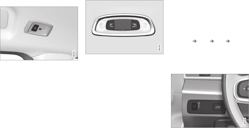
||
INSTRUMENTS AND CONTROLS
* Option/accessory, for more information, see Introduction.
144
Rear interior lighting
Rear reading lights
Rear reading lights: second row of seats
The rear interior lighting/reading lights are
located in the ceiling.
Turn them on or off by briefly pressing the button
in the side console. Adjust the brightness by
pressing and holding the button.
Rear courtesy lighting
Rear reading lights: third row of seats*
The rear courtesy lighting is turned on or off by
briefly pressing the button in the ceiling console.
Adjust the brightness by pressing and holding
the button.
Glove compartment lighting
The glove compartment lighting comes on or
goes off when the glove compartment is opened
or closed.
Vanity mirror lighting
The vanity mirror lighting comes on or goes off
when the cover over the mirror is opened or
closed.
Cargo area lighting
The cargo area lighting comes on or goes off
when the tailgate is opened or closed.
Ground lighting
The ground lighting comes on or goes off when a
door is opened or closed.
Doorsill lighting
The doorsill lighting comes on or goes off when a
door is opened or closed.
Ambience lighting
1. In the center display's Top view, select
Settings My Car Lights Ambient
Lighting
2. Choose among the following settings:
•Under Ambient Light Intensity, choose:
Off, Low or High.
•Ambient Light Level: Reduced or Full.
The ambience lighting can also be fine-tuned using the
thumb wheel (on the dashboard to the left of the steer-
ing wheel)
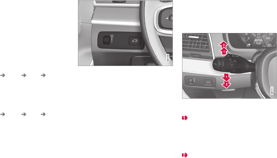
INSTRUMENTS AND CONTROLS
}}
* Option/accessory, for more information, see Introduction. 145
Mood lighting*
When the overhead courtesy lighting has gone
out and the engine is running, several LEDs
located near the roof console illuminate to pro-
vide faint lighting to help e.g., see objects in stor-
age compartments. This lighting goes out just
after the overhead courtesy lighting when the
vehicle is locked.
The following settings can be made for the mood
lighting in the center display:
Brightness
1. In the center display's Top view, select
Settings My Car Lights Interior
Mood Lighting.
2. Press Interior Mood Light Intensity and
choose Off, Low or High.
Change the color of the light
1. In the center display's Top view, select
Settings My Car Lights Interior
Mood Lighting.
2. Choose By Temperature, By Theme or
Theme Colors.
The intensity of the mood lighting can also be fine-tuned
using the thumb wheel (on the dashboard to the left of
the steering wheel)
Related information
•Lighting panel and controls (p. 135)
•Ignition modes (p. 360)
Using turn signals
The turn signals are controlled using the left
steering wheel lever. The turn signals flash three
times or continuously, depending on how far up
or down the lever is moved.
Turn signals
Short flashing sequence
The driver can automatically flash the turn
signals 3 times by moving the left steering
wheel lever up or down to the first position
and releasing it. This function can be acti-
vated/deactivated in the center display.
Continuous flashing sequence
Move the lever as far up or down as possible
to start the turn signals.
The turn signals will be cancelled automatically
by the movement of the steering wheel, or the
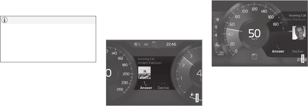
||
INSTRUMENTS AND CONTROLS
146
lever can be returned to its initial position by
hand.
NOTE
•This automatic flashing sequence can be
interrupted by immediately moving the
lever in the opposite direction.
•If the turn signal indicator flashes faster
than normal, check for a burned-out turn
signal bulb.
Related information
•Lighting panel and controls (p. 135)
•Hazard warning flashers (p. 141)
•Settings view (p. 107)
Messages in the instrument panel
and center display
Information and warning messages are dis-
played in the instrument panel and center dis-
play.
Instrument panel
Message in the instrument panel (12" version)
Message in the instrument panel (8" version)
High-priority messages are displayed in the
instrument panel.
Messages may appear in different parts of the
instrument panel depending on their context. The
message will time out after a short period of time
or disappear when it has been confirmed or if
action has been taken. Messages that need to be
stored will be saved under My car messages in
the center display's Top view.
The message may be displayed along with graph-
ics, symbols or buttons for e.g., confirming the
message or accepting a request.

INSTRUMENTS AND CONTROLS
}}
147
Service messages
The following table lists a selection of important
service messages and the action that should be
taken.
Message Action
Stop safelyAStop and switch off the
engine. There is a risk of
serious damage to the vehi-
cleB.
Turn off
engineA
Stop and switch off the
engine. There is a risk of
serious damage to the vehi-
cleB.
Service
urgent Drive
to workshopA
Contact a workshopB to have
the vehicle inspected imme-
diately.
Service
requiredA
Contact a workshopB to have
the vehicle inspected as
soon as possible.
Book time for
maintenance
Time for
maintenance
Time for the next scheduled
service. Contact a work-
shopB.
Message Action
Maintenance
overdue
Time for the next scheduled
service. Contact a work-
shopB. If the service sched-
ule is not followed, this may
void all or part of the vehi-
cle's warranty and result in
damage to vehicle compo-
nents.
Temporarily
offA
A function has been tempo-
rarily deactivated and will be
reactivated automatically
while driving or after the
engine is restarted.
APart of the message is context-dependent.
BContact a Volvo retailer or a trained and qualified Volvo service
technician.
Center display
Message in the center display's status bar
Messages with lower priority for the driver are
shown in the center display.
Most of the messages are shown in the center
display's status bar. The message times out after
a short period of time or disappears if it has been
confirmed or if action has been taken. Messages
that need to be stored are saved under My car
messages in Top view.
Some messages in the center display contain
one or more buttons for e.g., confirming the mes-
sage or accepting a request.
Messages' form can vary and they may be dis-
played with graphics, symbols or buttons for e.g.,
confirming a message or accepting a request.
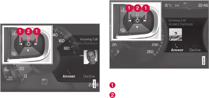
||
INSTRUMENTS AND CONTROLS
148
Pop-up messages
Messages are sometimes displayed in pop-up
windows. Messages of this type have higher pri-
ority than ones in the status bar and must be
confirmed or action must be taken before they
disappear. Messages that need to be stored are
saved under My car messages in Top view.
Related information
•Instrument panel (p. 123)
•Center display overview (p. 28)
Handling messages in the
instrument panel and center display
Instrument panel
Message in the instrument panel (8" version) and the
right-side steering wheel keypad
Message in the instrument panel (12" version) and the
right-side steering wheel keypad
Left/right arrow keys
Confirm
Some messages in the instrument panel contain
one or more buttons for e.g., confirming a mes-
sage or accepting a proposal.
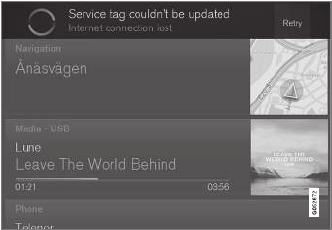
INSTRUMENTS AND CONTROLS
149
Handling new messages
For messages with buttons:
1. Navigate among the buttons available by
pressing the left/right arrow keys (1).
2. Confirm a choice by pressing (2).
> The message will disappear from the
instrument panel.
For messages without buttons:
–Close the message by pressing (2) or let the
message time-out after a short period.
> The message will disappear from the
instrument panel.
If a message needs to be saved, it will be stored
in the Car status app, which can be opened in
the center display's App view. Car message
stored in Car status application will be dis-
played at this time in the center display.
Center display
Message in the center display
Some buttons in the center display have a button
(or several buttons in a pop-up) to make it possi-
ble to e.g., activate/deactivate a function related
to the message.
Handling new messages
For messages with buttons:
–Tap the button to carry out the action or let
the message time-out after a short period.
> The message will disappear from the cen-
ter display's status bar.
For messages without buttons:
–Close the message by tapping it or let the
message time-out after a short period.
> The message will disappear from the cen-
ter display's status bar.
If a message needs to be saved, it will be stored
in the center display's Top view.
Related information
•Messages in the instrument panel and center
display (p. 146)
•Using the instrument panel App menu
(p. 151)
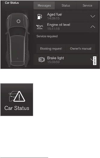
INSTRUMENTS AND CONTROLS
150
Handling messages stored from the
instrument panel and center display
Messages saved from the instrument
panel
Saved messages and possible selections in the Car
status app
Messages that have been dis-
played in the instrument panel
and need to be saved are
stored in the Car status app,
which can be opened in the
center display's App view. Car
message stored in Car
status application will be displayed at this time
in the center display.
Reading saved messages
Reading a saved message immediately:
–Tap the button to the right of the message
Car message stored in Car status
application in the center display.
> The saved message will be displayed in
the Car status app.
Reading a saved message at a later time:
1. Open the Car status app in the center dis-
play's App view.
> The app will open in Home view's lowest
sub-view.
2. Select the Messages tab in the app.
> A list of saved messages will be displayed.
3. Tap the arrow to the right to expand/mini-
mize the message.
> More information about the message will
appear in the list and the image to the left
in the app will show information about the
message in graphic form.
Handling a saved message
In expanded form, some messages have two but-
tons for booking service or reading the owner's
manual.
Booking service:
–With the message in expanded form, tap
Request appoint./Call to make
Appointment13 to book a service/repair
appointment.
>Request appoint.: the Appointments
tab will open in the app and create a
request for a service/repair appointment.
Call to make Appointment: the phone
app will start and initiate a call to your pre-
ferred retailer to make a service/repair
appointment.
Reading the owner's manual:
–With the message in expanded form, tap
Owner's manual to read the section of the
owner's manual related to the message.
> The owner's manual will open in the cen-
ter display and provide information related
to the message.
Messages stored in the app will be erased auto-
matically each time the engine is started.
13 Certain markets only.
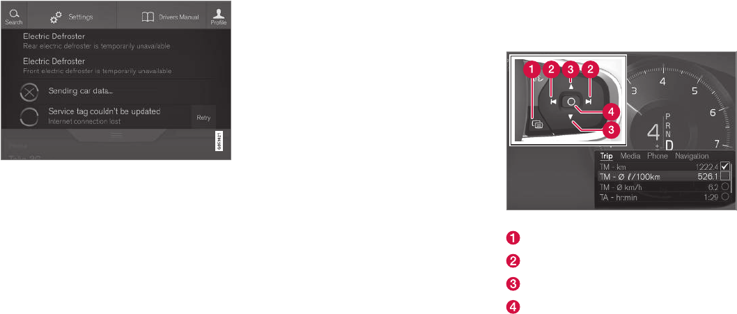
INSTRUMENTS AND CONTROLS
}}
151
Messages saved from the center
display
Saved messages and possible selections in Top view
Messages that have been shown in the center
display and need to be saved are stored in the
center display's Top view.
Reading a saved message
1. Open the center display's Top view.
> A list of saved messages will be displayed.
The ones with an arrow to the right can
be expanded.
2. Tap the arrow to the right to expand/mini-
mize the message.
Handling a saved message
Some messages have a button to e.g., activate/
deactivate a function related to the message.
–Tap the button to carry out the action.
Messages saved in Top view are erased automat-
ically when the engine is switched off.
Related information
•Handling messages in the instrument panel
and center display (p. 148)
Using the instrument panel App
menu
The App (application) menu in the instrument
panel is controlled using the right-side steering
wheel keypad.
App menu and right-side steering wheel keypad
App menu
Left/right
Up/down
Confirm
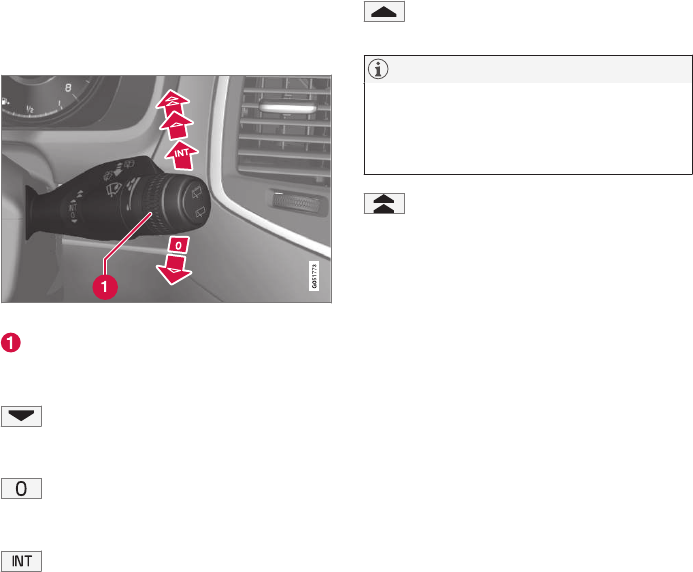
||
INSTRUMENTS AND CONTROLS
* Option/accessory, for more information, see Introduction.
152
Opening/closing the App menu
–Press the App menu (1).
The App menu cannot be opened if there are
unread/unconfirmed messages in the instru-
ment panel. The message must be confirmed
before the App menu can be opened.
> The App menu opens/closes.
The App menu closes automatically after a period
of inactivity or after certain selections are made.
Navigating and making selections in the
App menu
1. Navigate between the various apps by press-
ing left or right (3).
> Functions for the preceding/next app will
be displayed in the App menu.
2. Scroll through the current app's selections
using up or down (4).
3. Confirm or select a function by pressing (2).
> The function will be activated and in cer-
tain cases, the App menu will close.
Related information
•Instrument panel App menu (p. 126)
Using the windshield wipers
Before using the wipers, ice and snow should
be removed from the windshield. Be sure the
wiper blades are not frozen in place.
Right-side steering wheel lever
Thumb wheel to set rain sensor* sensitivity/
interval wiper speed
Single sweep
Move the lever down and release it for a
single sweep.
Wipers off
Move the lever to position 0 to turn off
the windshield wipers.
Interval wipers
Set the wiper interval speed by moving
the thumb wheel upward or downward.
Continuous wipers
Move the lever upward for the wipers to
operate at normal speed.
NOTE
Before using the wipers, be sure that the
wiper blades are not frozen onto the wind-
shield and that any ice or snow on the wind-
shield has been removed.
Move the lever upward to the next posi-
tion for maximum wiper speed.
Related information
•Tailgate window wiper and washer (p. 155)
•Activating/deactivating the rain sensor
(p. 153)
•Windshield and headlight washers (p. 154)
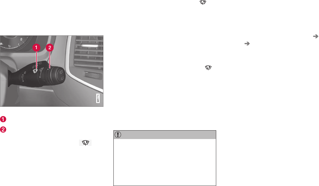
INSTRUMENTS AND CONTROLS
153
Activating/deactivating the rain
sensor
The rain sensor monitors the amount of water on
the windshield and automatically regulates wiper
speed.
Right-side steering wheel lever
Rain sensor button
Thumb wheel for adjusting sensitivity/interval
wiper speed
When the rain sensor is activated, the
symbol will illuminate in the instrument panel.
Activating the rain sensor
When activating the rain sensor, the engine must
be running or the ignition must be in mode I or II.
The windshield wiper lever must also be in posi-
tion 0 or in the single sweep position.
Activate the rain sensor by pressing the
button. The wipers will make one sweep.
If the lever is pressed down, the wipers will make
additional sweeps across the windshield.
Move the thumb wheel upward for increased sen-
sitivity or downward for decreased sensitivity. The
wipers will make one extra sweep if the thumb
wheel is moved upward.
Deactivating the rain sensor
Deactivate the rain sensor by pressing the
button or by moving the lever upward to another
wiper position.
The rain sensor is automatically deactivated in
ignition mode 0.
The rain sensor is also automatically deactivated
when the wipers blades are put in the service
position and will reactivate when the wipers have
been returned to the normal operating position.
CAUTION
Deactivate the rain sensor when washing the
vehicle in an automatic car wash if the engine
is running or if the ignition is left in mode I or
II. The symbol in the instrument panel will go
out. If the rain sensor is not deactivated, the
wipers may start inadvertently in the car wash
and could be damaged.
Activating/deactivating the memory
function
The rain sensor's memory function can be set to
activate the rain sensor each time the engine is
started:
1. In the center display, select Settings My
Car Wipers
2. Activate by selecting the Rain Sensor
Memory box.
Deactivate by deselecting the Rain Sensor
Memory box.
Related information
•Using the windshield wipers (p. 152)
•Windshield wipers in the service position
(p. 532)
•Tailgate window wiper and washer (p. 155)
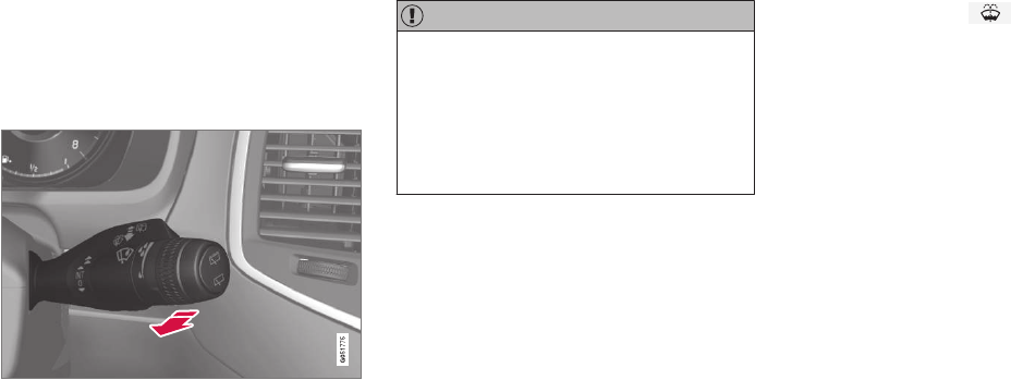
INSTRUMENTS AND CONTROLS
* Option/accessory, for more information, see Introduction.
154
Windshield and headlight washers
Use the windshield/headlight washers to help
improve visibility.
Starting the windshield and headlight
washers
Washing function
–Move the right-side steering wheel lever
toward the wheel to start the windshield and
headlight washers.
> After the lever is released the wipers
make several extra sweeps.
CAUTION
•Use ample washer fluid when washing
the windshield. The windshield should be
thoroughly wet when the wipers are in
operation.
•Avoid using the washers if the fluid reser-
voir is frozen or empty to help avoid dam-
age to the pump.
When the washing system is used, the length of
time that the windshield washers operate
depends on the ambient temperature. In cold
weather, the amount of washer fluid used will
also be increased automatically to help improve
cleaning.
Heated washer nozzles*
The washer nozzles are heated automatically in
cold weather to help prevent the washer fluid
from freezing.
High-pressure headlight washing*
High-pressure headlight washing consumes a
large quantity of washer fluid. To save fluid, the
headlights are washed once for every five times
the windshield is washed.
Reduced washing
When approx. 1 US quart (1 liter) of washer fluid
remains in the reservoir, the headlights will no
longer be washed to conserve fluid.
A text message and the symbol will be dis-
played in the instrument panel to remind the
driver to fill the washer fluid reservoir.
Related information
•Refilling the windshield washer fluid reservoir
(p. 534)
•Using the windshield wipers (p. 152)
•Tailgate window wiper and washer (p. 155)
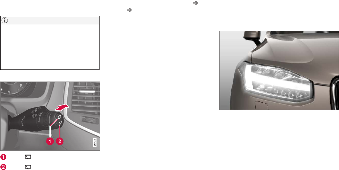
INSTRUMENTS AND CONTROLS
}}
* Option/accessory, for more information, see Introduction. 155
Tailgate window wiper and washer
Start the tailgate window wiper/washer with con-
trols on the right-side steering wheel lever.
NOTE
The rear wiper is equipped with a cut-off
function, which means that it will not operate
if its electric motor overheats. The wiper will
function again after a cool-down period
(30 seconds or longer, depending on the heat
of the motor and ambient temperature condi-
tions).
Using the tailgate wiper/washer
Press for tailgate interval wiper
Press for tailgate continuous wiper
–Move the lever forward to wash/wipe the tail-
gate window.
Tailgate wiper and reverse gear
1. In the center display, select Settings My
Car Wipers.
2. Activate/deactivate by selecting/deselecting
the Auto Rear Wiper box.
If the windshield wipers are on and the transmis-
sion is put into reverse gear, the tailgate wiper
will start. This function is deactivated when a dif-
ferent gear is selected.
Related information
•Using the windshield wipers (p. 152)
•Windshield and headlight washers (p. 154)
•Refilling the windshield washer fluid reservoir
(p. 534)
•Activating/deactivating the rain sensor
(p. 153)
Steering wheel
The steering wheel has controls for the horn,
certain optional driver support systems, menus/
messages and paddles for manually shifting
gears*.
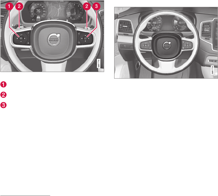
||
INSTRUMENTS AND CONTROLS
* Option/accessory, for more information, see Introduction.
156
Steering wheel keypads and paddles*
Driver support system controls14
Paddles for manually shifting gears*
Keypad for voice controls, adjusting the
head-up display*accessing menus and mes-
sages, and handling phone calls
Horn
The horn is located in the steering wheel hub.
Related information
•Adjusting the steering wheel (p. 157)
•Turning steering wheel heating* on and off
(p. 188)
•Cruise Control (CC) (p. 251)
•Speed limiter (SL)* (p. 288)
•Adaptive Cruise Control (ACC)* (p. 256)
•Distance Alert* (p. 319)
•Pilot Assist* (p. 263)
•Steering wheel paddles* (p. 377)
•Voice control (p. 116)
•Head-up display (HUD)* (p. 113)
•Using the instrument panel App menu
(p. 151)
•Phone (p. 393)
14 Cruise control*, Speed limiter *, Adaptive cruise control*, Distance alert* and Pilot Assist*.
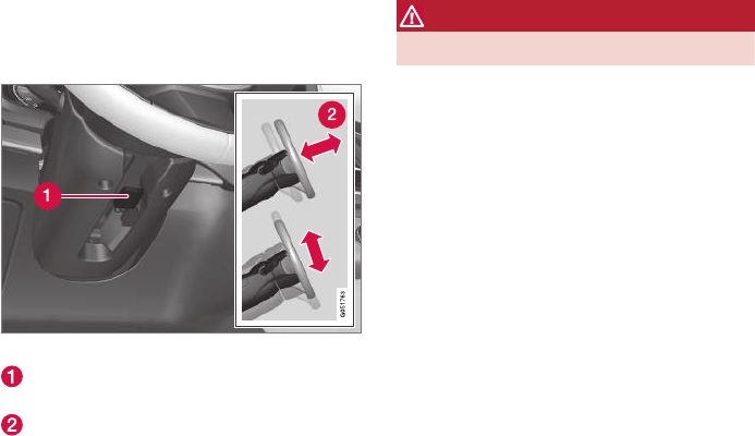
INSTRUMENTS AND CONTROLS
}}
* Option/accessory, for more information, see Introduction. 157
Adjusting the steering wheel
The steering wheel can be adjusted to various
positions.
Adjusting the steering wheel
Lever for releasing/locking the steering
wheel
Possible positions
The steering wheel's height and reach can be
adjusted. To do so:
1. Push the lever down to release the steering
wheel.
2. Adjust the steering wheel to a suitable posi-
tion.
3. Pull back the lever to lock the steering wheel
in place. If the lever is difficult to pull into
place, press the steering wheel lightly at the
same time as you pull the lever.
WARNING
Never adjust the steering wheel while driving.
If the vehicle is equipped with the optional
speed-dependent power steering, the level of
steering force can be adjusted. The force level is
adjusted according to the vehicle's speed.
Related information
•Steering wheel (p. 155)
•Adjustable steering force* (p. 313)
Seats
The vehicle can be equipped with 5 or 7 seats*.
The front seats can be adjusted electroncially or
manually. The second and third row* seats are
adjusted primarily manually.
The adjustment settings for the power front
seats*, door mirrors and the head-up display can
be stored in memory buttons.
Using the multi-function control*, comfort in the
front seats can be further enhance by e.g., adjust-
ing the lumbar support or extending the length of
the front seat cushion.
The rear seats can be folded down and their
head restraints can be adjusted. The second row
seats can be moved forward/rearward and their
backrest tilt can also be changed.
Related information
•Adjusting power front seats* (p. 159)
•Adjusting function settings in the multifunc-
tional front seats* (p. 162)
•Manually operated front seats (p. 158)
•Using the power seat memory function*
(p. 160)
•Folding the second row backrests (p. 168)
•Getting into and out of the third row of seats
(p. 170)

INSTRUMENTS AND CONTROLS
* Option/accessory, for more information, see Introduction.
158
•Moving the second row seats forward/rear-
ward (p. 170)
•Adjusting the second row backrest tilt
(p. 167)
Manually operated front seats
The front seats can be adjusted in a number of
ways to help provide the most comfortable seat-
ing position.
Raise/lower the front edge of seat cushion
by pumping up/down
Move the seat forward/rearward by pulling
the bar upward and moving the seat.
Change lumbar support by pressing the but-
ton*
Raise/lower the seat by moving the control
up/down
Change backrest tilt by turning the wheel
WARNING
•Do not adjust the seat while driving. The
seat should be adjusted so that the brake
pedal can be depressed fully. In addition,
position the seat as far rearward as com-
fort and control allow.
•Check that the seat is securely locked
into position after adjusting.
Related information
•Turning seat heating* on and off (p. 190)
•Power front seats* (p. 159)
•Multifunctional front seats* (p. 161)
•Seat belts (p. 60)
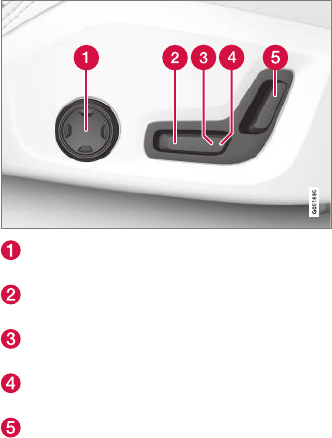
INSTRUMENTS AND CONTROLS
* Option/accessory, for more information, see Introduction. 159
Power front seats*
The power front seats offer a number of adjust-
ment possibilities to help maximize comfort and
ergonomics.
The power seats have an overload protector that
activates if a seat is blocked by any object. If this
occurs, put the ignition in mode I or 0 and wait
for a short period before operating the seat
again.
The power seat(s) can be adjusted for a short
period after unlocking the door with the remote
key without switching the ignition on. Seat adjust-
ment can always be made when the engine is
running.
Related information
•Multifunctional front seats* (p. 161)
•Adjusting power front seats* (p. 159)
•Using the power seat memory function*
(p. 160)
•Manually operated front seats (p. 158)
•Turning seat heating* on and off (p. 190)
•Turning front seat ventilation* on and off
(p. 192)
•Easy access to and from the driver seat
(p. 165)
Adjusting power front seats*
The power front seat(s) can be adjusted to many
positions to help improve comfort and ergonom-
ics.
Adjust lumbar support by pressing the con-
trol up/down/forward/rearward
Raise/lower the front edge of the seat cush-
ion by moving the control up/down
Raise/lower the seat by moving the control
up/down
Move the seat forward/rearward by moving
the control forward/rearward
Change backrest tilt by moving the control
forward/rearward
Only one of the power seat's controls can be
used at the same time.
The front seat backrests can be folded down
completely.
Related information
•Power front seats* (p. 159)
•Using the power seat memory function*
(p. 160)
•Multifunctional front seats* (p. 161)
•Seat belts (p. 60)
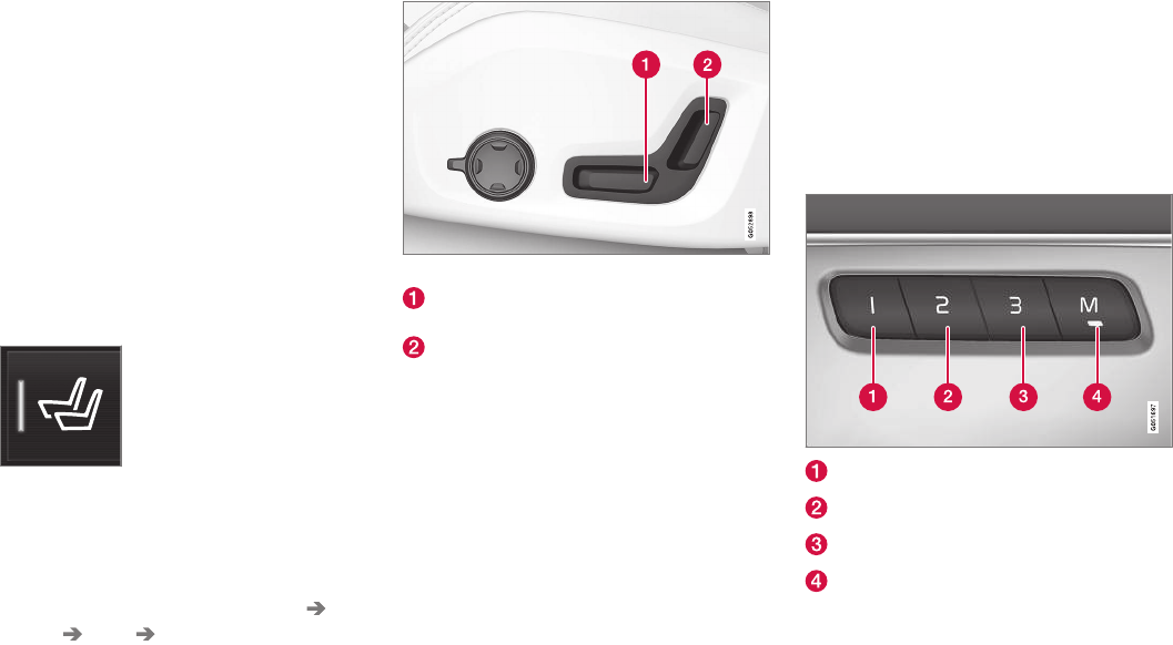
INSTRUMENTS AND CONTROLS
* Option/accessory, for more information, see Introduction.
160
Adjusting the passenger's seat from
the driver's seat*
Using the controls on the side of the driver's
seat, the driver can adjust the position of the
front passenger's seat.
Activating the function in the center
display
From the center display, the function can be acti-
vated in two ways.
After activating the function, adjust the passeng-
er's seat within 10 seconds. If no adjustments
are made in that time span, the function deacti-
vates automatically.
Activating from Function view
1. Go to the center display's Function view.
2. Activate the function by tapping Adjust
passenger seat.
Activating from Settings
–In the center display, select Settings My
Car Seats Adjust Passenger Seat
From Driver Position.
Power seat controls
Move the passenger's seat forward/rearward
by moving the control forward/rearward.
Change the passenger seat's backrest tilt by
moving the control forward/rearward.
Related information
•Power front seats* (p. 159)
•Adjusting power front seats* (p. 159)
•Seat belts (p. 60)
Using the power seat memory
function*
The memory function can be used to store the
settings (positions) of the power front seats*,
door mirrors and the head-up display. Three dif-
ferent settings can be stored using this function.
Memory controls are found on one or both of the
front doors*.
Button for storing a position
Button for storing a position
Button for storing a position
M (memory) button
Storing a position
1. Adjust the seat, door mirrors and head-up
display to the desired positions.

INSTRUMENTS AND CONTROLS
}}
* Option/accessory, for more information, see Introduction. 161
2. Press and release the M button. The indica-
tor light in the button will illuminate.
3. Press button 1, 2 or 3 within 3 seconds to
store the current position of the seat/
mirrors/head-up display in the selected but-
ton.
> When the position has been stored in the
selected button, an audible signal will
sound and the indicator light in the M but-
ton will go out.
If none of the buttons (1, 2 or 3) is pressed
within 3 seconds, the indicator light in the M but-
ton will go out and the position will not be stored.
The seat/mirrors/head-up display must be
moved before a new position can be stored.
Using a stored position
A stored position can be used when one of the
front doors is opened or closed:
Front door open
–Press one of the bottons (1–3) briefly. The
seat, door mirrors and head-up display will
move to the positions stored in that button.
Front door closed
–Press and hold one of the buttons (1–3) until
the seat, door mirrors and head-up display
have moved to the positions stored in that
button.
The seat, door mirrors and head-up display will
stop automatically if the button is released before
the they have reached the stored positions.
WARNING
•Because the driver's seat can be adjusted
with the ignition off, children should never
be left unattended in the vehicle.
•Movement of the seat can be STOPPED
at any time by pressing any button on the
power seat control panel.
•Do not adjust the seat while driving. The
seat should be adjusted so that the brake
pedal can be depressed fully. In addition,
position the seat as far rearward as com-
fort and control allow.
•The seat rails on the floor must not be
obstructed in any way when the seat is in
motion.
Related information
•Adjusting power front seats* (p. 159)
•Power front seats* (p. 159)
Multifunctional front seats*
In addition to the adjustment settings offered by
the power seat controls, the multifunction control
provides additional possibilities for convenience
and comfort.
Multifunction control on the side of the seat
The multifunction control can be used to adjust
lumbar support*, the backrest's side bolsters*, the
length of the seat cushion and the massage
function*. The adjustment settings made with the
control are shown in the center display* and cer-
tain settings can be made directly from the cen-
ter display.
Center display
The adjustment settings for the driver and pas-
senger seats made using the multifunction con-
trol are shown in the center display. If only one
seat is adjusted, the settings are shown in the
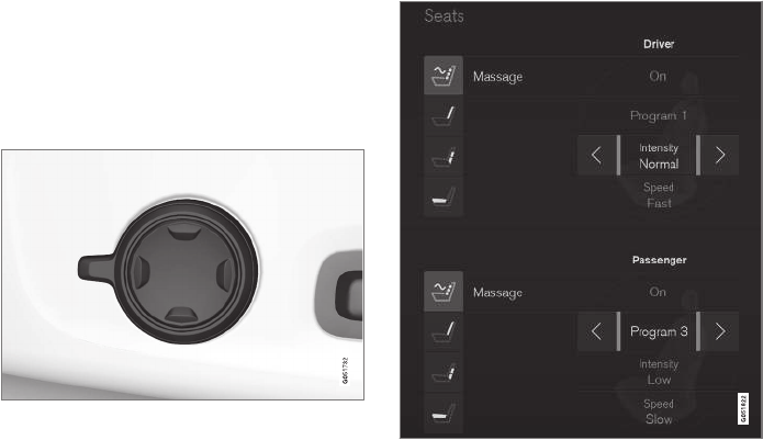
||
INSTRUMENTS AND CONTROLS
* Option/accessory, for more information, see Introduction.
162
center of the display. If both seats are adjusted,
the settings for the driver seat are shown on the
upper half of the screen and the ones made for
the passenger seat are on the lower half.
Press the Home button on the center console to
exit the seat adjustment setting view.
Related information
•Power front seats* (p. 159)
•Adjusting function settings in the multifunc-
tional front seats* (p. 162)
•Turning seat heating* on and off (p. 190)
Adjusting function settings in the
multifunctional front seats*
The multifunction controls on the side of the seat
as well as the center display can be used to
make seat adjustments. The adjustment settings
are shown in the center display*.
Multifunction control on the side of the seat
Turn the control up or down to activate.
Front seat massage settings*
The front seat backrests have a massage func-
tion. Air-filled cushions provide the massaging
action and a number of settings are available.
The massage function can only be used when
the engine is running.
Massage view in the center display
1. Activate the multifunction control by turning
it up or down. Seat settings will be displayed
in the center display.
2. Tap Massage in the seat settings view.
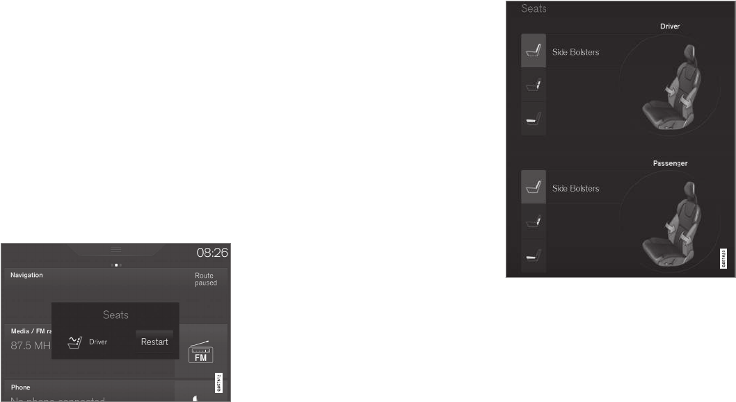
INSTRUMENTS AND CONTROLS
}}
* Option/accessory, for more information, see Introduction. 163
3. Select massage settings by tapping the cen-
ter display or by moving the cursor up/down
using the multifunction control's upper/lower
buttons. Change a setting in the selected
function by tapping the arrows on the center
display or by using the multifunction control's
front/rear buttons.
Massage settings
The following massage settings are available:
•On/Off.
•Program 1-5: There are 5 preset massage
programs. Select Swell, Tread, Advanced,
Lumbar or Shoulder.
•Intensity: Select Low, Normal or High.
•Speed: Select Slow, Normal or Fast.
Restarting the massage function
Massage restart button in the center display
The massage function switches off automatically
after 20 minutes and must be restarted manually
for continued use.
Tap Restart in the center display to restart the
selected massage program.
Adjusting the side bolsters in the front
seats*
The side bolsters in the front seat backrests can
be inflated/deflated to adjust the amount of sup-
port provided.
Side bolster view in the center display
1. Activate the multifunction control on the side
of the seat by moving it up/down. The seat
settings view will appear in the center dis-
play.
2. Select Side bolsters in the seat settings
view.
•Tap the front button to increase bolster
support.
•Tap the rear button to decrease bolster
support.
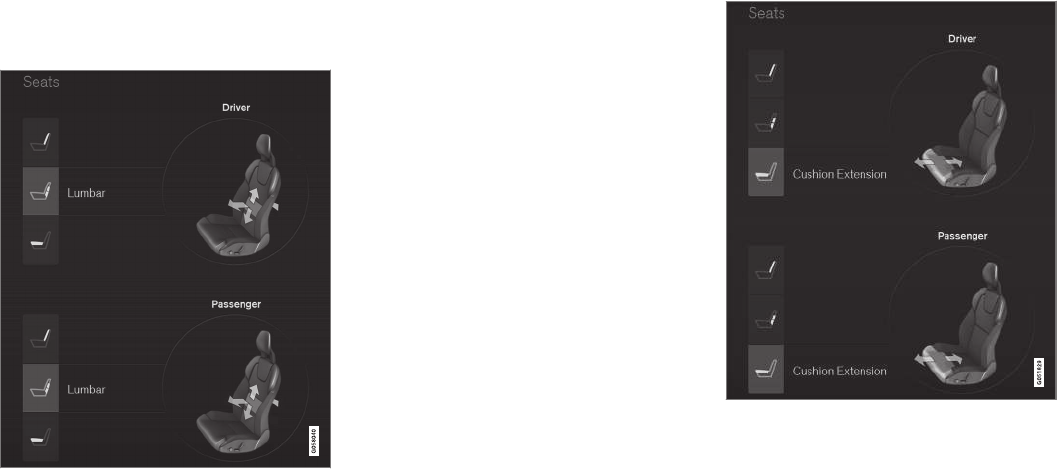
||
INSTRUMENTS AND CONTROLS
* Option/accessory, for more information, see Introduction.
164
Adjusting front seat lumbar support*
Lumbar support can be adjusted up/down/front/
rear.
Lumbar support view in the center display
1. Activate the multifunction control on the side
of the seat by moving it up/down. The seat
settings view will appear in the center dis-
play.
2. Select Lumbar in the seat settings view.
•Tap the button up/down to move lumbar
support up/down.
•Tap the front button to make lumbar sup-
port firmer.
•Tap the rear button to make lumbar sup-
port softer.
Extending the seat cushion
The seat cushion can be extended/retracted
using the multifunction control.
Seat cushion extension view in the center display
1. Activate the multifunction control on the side
of the seat by moving it up/down. The seat
settings view will appear in the center dis-
play.
2. Select Cushion extension in the seat set-
tings view.
•Tap the front button to extend the cush-
ion.
•Tap the rear button to retract the cushion.
INSTRUMENTS AND CONTROLS
}}
* Option/accessory, for more information, see Introduction. 165
Related information
•Multifunctional front seats* (p. 161)
Rear seats
Your vehicle has two or three* rows of seats.
The second row of seats has three individual
seating positions and the optional third row of
seats has two individual seating positions.
Related information
•Adjusting the second row backrest tilt
(p. 167)
•Adjusting the second row head restraints
(p. 166)
•Folding the second row backrests (p. 168)
•Folding the third row* backrests (p. 171)
•Getting into and out of the third row of seats
(p. 170)
•Moving the second row seats forward/rear-
ward (p. 170)
•Turning seat heating* on and off (p. 190)
Easy access to and from the driver
seat
The Easy Ingress & Egress function can be
used to make getting into and out of the driver's
seat easier.
Easy egress
To make getting out of the driver's seat easier,
the seat is lowered, the side bolsters deflate and
the seat cushion retracts at the same time.
The easy egress function must be activated in
the center display.
1. Move the gear selector to the P position.
2. Switch off the engine.
3. Unbuckle the seat belt.
4. Open the driver's door.
> The seat, side bolsters and seat cushion
all move at the same time to a position
that makes it easier to leave the seat.
Easy ingress
The seat remains in the easy egress position
when the driver leaves the vehicle. When the
driver returns to the vehicle, the seat is in a posi-
tion to make sitting down easier. When the driver
is seated, has buckled the seat belt and has put
the ignition in at least mode 1, the seat will return
to the driver's preferred position.
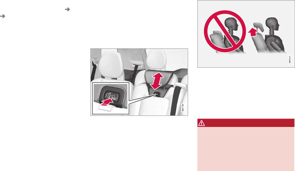
||
INSTRUMENTS AND CONTROLS
* Option/accessory, for more information, see Introduction.
166
Activating/deactivating the function
1. In the center display, select Settings My
Car Seats.
2. Activate/deactivate the function by select-
ing/deselecting the Easy Ingress & Egress
box.
Related information
•Power front seats* (p. 159)
•Ignition modes (p. 360)
Adjusting the second row head
restraints
The center head restraint in the second row of
seats can be adjusted to suit the height of the
seat's occupant. The outboard head restraints
can be folded down* for a better rear view.
Adjusting the center head restraint
Center head restraint button
The center head restraint should be adjusted up
or down according to the passenger's height. The
restraint should be carefully adjusted to support
the occupant's head.
To lower the head restraint, press and hold the
button (see the illustration) and push the head
restraint down carefully.
WARNING
The center rear seat head restraint should
only be in its lowest position when this seat is
NOT occupied. When the center position is
occupied, the head restraint should be cor-
rectly adjusted to the passenger’s height. The
upper edge of the head restraint should be at
least on a level with the upper-most point of
the seat occupant's ear.
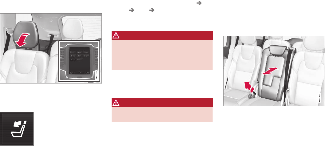
INSTRUMENTS AND CONTROLS
}}
* Option/accessory, for more information, see Introduction. 167
Electrically folding down the rear seat’s
outboard head restraints*
The outboard head restraints can be folded down
in two ways from the center display.
From Function view
1. Go to the center display's Function view.
2. Tap the Headrest fold button.
Via settings
1. The ignition has to be in at least mode II.
2. In the center display, select Settings My
Car Seats Fold Headrest On
Second Row Seats to fold down the out-
board head restraints.
WARNING
For safety reasons, no one should be allowed
to sit in the outboard rear seat positions if the
head restraints are folded down. If these posi-
tions are occupied, the head restraints should
be in the upright (fixed) position.
The head restraints must be returned to the
upright position manually until they click into
position.
WARNING
The head restraint must be locked in the
upright position after it has been folded up.
Related information
•Folding the second row backrests (p. 168)
•Center display overview (p. 28)
Adjusting the second row backrest
tilt
Backrest tilt can be adjusted separately for each
of the second row seats.
Center seat
1. Pull the strap on the center seat's right side.
2. Adjust backrest tilt forward/rearward by
decreasing/increasing pressure on it.
3. Release the strap to lock the backrest in the
new position and press the backrest until its
lock engages.
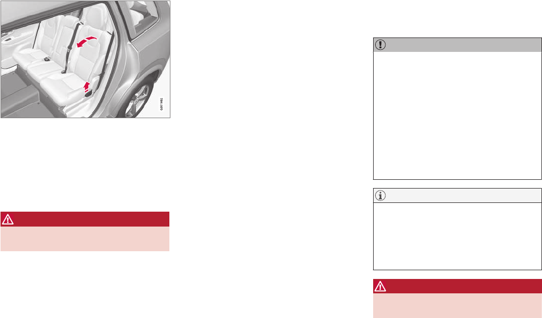
||
INSTRUMENTS AND CONTROLS
* Option/accessory, for more information, see Introduction.
168
Outboard seats
1. Pull the handle on the side of the seat
upward.
2. Adjust backrest tilt forward/rearward by
decreasing/increasing pressure on it.
3. Release the handle to lock the backrest in
the new position and press the backrest until
its lock engages.
WARNING
Check that all backrests are securely locked
in place after changing the tilt angle.
Related information
•Rear seats (p. 165)
•Moving the second row seats forward/rear-
ward (p. 170)
•Folding the second row backrests (p. 168)
•Seat belts (p. 60) Folding the second row backrests
The second row of seats has three individual
seating positions whose backrests can be
folded down separately.
CAUTION
•To help avoid damage to the seat uphols-
tery, before a rear seat backrest is folded
down, remove any objects from the seat
and ensure that the seat belts are not
buckled.
•The integrated booster cushion* in the
center position must be stowed (folded
down) before the backrest is folded
down.
•The center seating position armrest must
be folded up before the backrest is
folded down.
NOTE
•It may be necessary to adjust the front
seat backrests and/or move these seats
forward in order to fold down the rear
seat backrests completely.
•It may also be necessary to move the
second row of seats rearward.
WARNING
Adjust the seat and be sure it is locked in the
new position before driving.

INSTRUMENTS AND CONTROLS
* Option/accessory, for more information, see Introduction. 169
Center seat
To fold down the backrest:
1. Fold down the head restraint manually.
2. Pull the strap on the center seat's right side.
3. Fold the backrest down until it locks in posi-
tion. The seat cushion will move downward/
forward as the backrest is folded down to
create a flat surface.
To return the backrest to the upright position:
1. Pull the strap.
2. Fold the backrest and release the strap.
Push it into position until its lock engages.
3. Adjust the head restraint if necessary.
Outboard seats
To fold down the backrest:
1. Pull up and hold the handle on the side of
the seat while the backrest is being folded
down.
2. Be sure that the backrest and head restraint
do not come in contact with the front seats
while they are being folded down. Fold down
until the backrest locks in place.
> The seat cushion will move downward/
forward as the backrest is folded down to
create a flat surface. The head restraint
folds down automatically when the back-
rest is folded down.
WARNING
After being folded down, be sure the back-
rests are securely locked in place.
To return the backrest to the upright position:
1. Pull up and hold the handle on the side of
the seat while the backrest is being folded
up.
2. Be sure that the backrest and head restraint
do not come in contact with the front seats
while they are being folded up. Fold up the
backrest and release the handle.
3. Press the backrest until its lock engages.
4. Fold up the head restraint manually.
WARNING
Be sure the backrest and head restraint are
securely locked in position after they have
been folded up.
Related information
•Rear seats (p. 165)
•Adjusting the second row backrest tilt
(p. 167)
•Folding the third row* backrests (p. 171)
•Adjusting the second row head restraints
(p. 166)
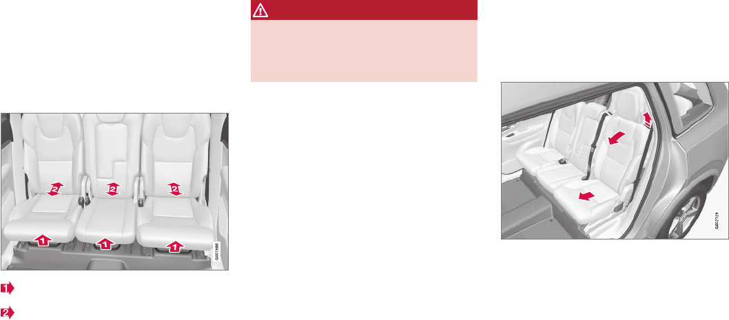
INSTRUMENTS AND CONTROLS
* Option/accessory, for more information, see Introduction.
170
Moving the second row seats
forward/rearward
In 7-seat models*, the second row seats can be
moved forward/rearward individually to help opti-
mize legroom for the passengers.
The second row seats cannot be moved in 5-
seat models.
Lift the handle located under the seat.
Move the seat forward/rearward to the
desired position.
3. Release the handle and move the seat so
that it locks in the new position.
WARNING
Be careful when moving the seat to avoid
injuries to your hands/fingers.
Check that the seat is securely locked in posi-
tion after being moved.
Related information
•Rear seats (p. 165)
•Getting into and out of the third row of seats
(p. 170)
Getting into and out of the third row
of seats
The second row seats can be moved for easier
access to the third row of seats*.
Getting into and out of a third row seat
To fold down the backrest:
1. Pull the handle on the upper side of one of
the outboard second row seats upward/
forward.
2. Fold the backrest forward and move the
entire seat forward.
To return the backrest to the upright position:
–Move the seat back and fold up the backrest
until it locks in position.
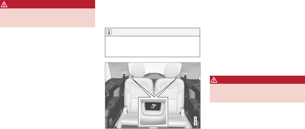
INSTRUMENTS AND CONTROLS
* Option/accessory, for more information, see Introduction. 171
WARNING
Be sure the backrest and head restraint are
securely locked in position after they have
been folded up.
Related information
•Moving the second row seats forward/rear-
ward (p. 170)
•Adjusting the second row backrest tilt
(p. 167)
•Folding the second row backrests (p. 168)
Folding the third row* backrests
The third row of seats has two individual seating
positions that can be folded down manually or
electrically*.
NOTE
Before folding down the third row seats, it
may be necessary to change the position/tilt
of the seats in the second row.
1. Pull the handle on the upper side of the
backrest upward/forward.
2. Be sure that the backrest and head restraint
do not come in contact with the seat ahead
while they are being folded down. Fold the
backrest down.
> The seat cushion will move downward/
forward as the backrest is folded down to
create a flat surface. The head restraint
folds down automatically when the back-
rest is folded down.
To return the backrest to the upright position,
fold the backrest up until it locks in position. The
head restraint has to be folded up manually.
WARNING
Be sure the backrest and head restraint are
securely locked in position after they have
been folded up.
Related information
•Rear seats (p. 165)
•Adjusting the second row head restraints
(p. 166)
•Adjusting the second row backrest tilt
(p. 167)
•Moving the second row seats forward/rear-
ward (p. 170)


CLIMATE
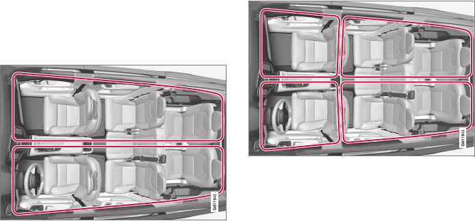
CLIMATE
* Option/accessory, for more information, see Introduction.
174
Climate control system
The vehicle is equipped with Electronic Climate
Control (ECC) that cools, heats, dehumidifies
and filters the air in the passenger compartment.
2-zone climate system
2-zone system climate zones
The 2-zone climate system makes it possible to
set the left- and right-side temperatures sepa-
rately.
All climate system settings are made from the
center display and the buttons in the center con-
sole.
4-zone climate system*
4-zone system climate zones
The 4-zone climate system makes it possible to
set the left- and right-side temperatures sepa-
rately for the front and rears seats.
All climate system settings are made from the
center display and the buttons in the center con-
sole. Settings for the rear seats can also be
made from the climate system panel on the rear
side of the tunnel console.
Related information
•Climate system sensors (p. 175)
•Perceived temperature (p. 174)
•Climate system controls (p. 178)
•Air quality (p. 175)
•Air distribution (p. 193)
•Air conditioning refrigerant (p. 552)
Perceived temperature
The climate system regulates passenger com-
partment temperature based on the perceived
temperature, not on the actual one.
The selected passenger compartment tempera-
ture is based on a physical perception relating to
the current ambient temperature, air flow, humid-
ity, sunlight in the passenger compartment, etc.
The system's sunlight sensor monitors the side of
the car where sunlight is entering the passenger
compartment. This means that the actual tem-
perature may differ between the right and left
sides of the compartment, even if the tempera-
ture setting is the same for both sides.
Related information
•Climate system sensors (p. 175)
•Climate control system (p. 174)
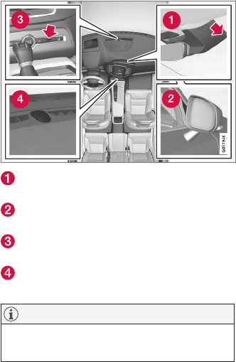
CLIMATE
* Option/accessory, for more information, see Introduction. 175
Climate system sensors
The climate system's sensors help regulate the
passenger compartment temperature, humidity
level, etc.
Location of the sensors
Humidity sensor: in the rearview mirror con-
sole.
Ambient temperature sensor: in the pas-
senger's side door mirror.
Passenger compartment temperature sen-
sor: near the center console buttons.
Sunlight sensor: on the upper side of the
dashboard.
NOTE
Do not cover or block the sensors with cloth-
ing or other objects.
On models equipped with the optional Interior Air
Quality System, there is also an air quality sensor
located at the climate system's air intake.
Related information
•Climate control system (p. 174)
•Perceived temperature (p. 174)
•Interior Air Quality System (IAQS)* (p. 176)
Air quality
The materials used in the passenger compart-
ment have been selected and designed to be
pleasant and comfortable, even for people with
asthma or other types of allergies.
Materials in the passenger
compartment
The materials used have been developed to help
minimize the amount of dust and make the cabin
easier to keep clean.
All floor mats can be easily removed for cleaning.
Use car cleaning products recommended by
Volvo.
Only use cleaning agents and car care products
recommended by Volvo. Clean regularly and fol-
low the instructions included with the car care
product.
Air filtering systems
In addition to the passenger compartment filter,
the Clean Zone Interior Package* and the Interior
Air Quality System* contribute to a cleaner pas-
senger compartment environment.
Related information
•Passenger compartment air filter (p. 177)
•Interior Air Quality System (IAQS)* (p. 176)
•Clean Zone Interior Package (CZIP)*
(p. 176)
•Cleaning the interior (p. 537)
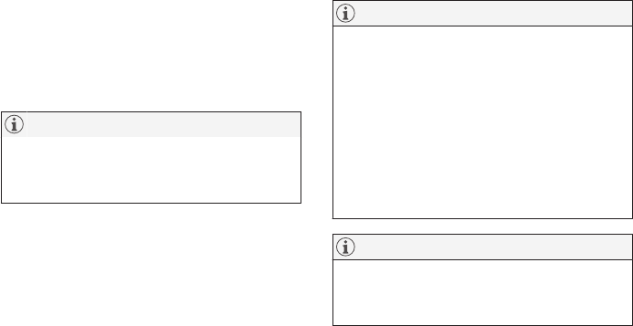
CLIMATE
* Option/accessory, for more information, see Introduction.
176
Clean Zone Interior Package
(CZIP)*
The Clean Zone Interior Package includes a
number of features that help further reduce aller-
genic substances in the passenger compart-
ment.
CZIP includes the following:
•An enhanced blower function that starts the
blower when the vehicle is unlocked with the
remote key to fill the passenger compart-
ment with fresh air. This function starts auto-
matically when required and shuts off auto-
matically after a short period or if one the
doors is opened. The time for which the
blower operates decreases gradually due to
reduced need until the vehicle is four years
old.
•The Interior Air Quality System (IAQS).
NOTE
In order to retain the CZIP standard, the IAQS
filter must be replaced at the specified inter-
vals. Consult your Volvo retailer.
Interior Air Quality System (IAQS)*
The Interior Air Quality System uses a multifilter
and an air quality sensor to remove gases, parti-
cles and other contaminants from the air enter-
ing the passenger compartment.
The IAQS air quality sensor monitors increased
levels of contaminants in the outside air and if
contaminants are detected, the air intake closes
and the air inside the passenger compartment is
recirculated, i.e., no outside air enters the vehicle.
The filter also cleans recirculated passenger
compartment air.
NOTE
•The air quality sensor should always be
engaged in order to obtain the best air in
the passenger compartment.
•Recirculation is limited in cold weather to
avoid fogging.
•If the insides of the windows start fog-
ging, disengage the air quality sensor.
Use the defroster function to increase
airflow to the front, side, and rear win-
dows.
NOTE
In order to retain the CZIP standard, the IAQS
filter must be replaced at the specified inter-
vals. Consult your Volvo retailer.
Activating/deactivating IAQS
To change the setting for IAQS activation/deacti-
vation:
1. In the center display's Settings view, go to
Climate.
2. Activate/deactivate IAQS by selecting/dese-
lecting the Air Quality Sensor box.
Related information
•Air quality (p. 175)
•Passenger compartment air filter (p. 177)
•Clean Zone Interior Package (CZIP)*
(p. 176)
•Turning recirculation on and off (p. 185)
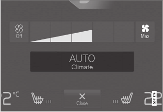
CLIMATE
* Option/accessory, for more information, see Introduction. 177
Passenger compartment air filter
All air entering the passenger compartment
through the climate system air intake is filtered.
Filter replacement
The filter must be replaced according to the serv-
ice schedule for your vehicle. When driving in e.g.,
dusty or industrial areas, the filer may need to be
replaced more often. Consult your Volvo retailer.
Related information
•Air quality (p. 175)
•Clean Zone Interior Package (CZIP)*
(p. 176)
•Interior Air Quality System (IAQS)* (p. 176)
•Volvo's service program (p. 496)
Automatic climate control
The Auto feature automatically controls a num-
ber of climate system functions.
The Auto climate button in Climate view
1. Go to the center display's Climate view.
2. Tap or press and hold AUTO.
> Auto mode is activated (button lights up)/
deactivated (button is off). Auto mode
automatically controls air recirculation, air
conditioning, and air distribution.
Blower speed and temperature change
depending on how long the button is
pressed.
•Tap: return to previous settings.
•Press and hold: change to default set-
tings (level 3 and 72 °F (22 °C).
Related information
•Climate system controls in the center display
(p. 178)
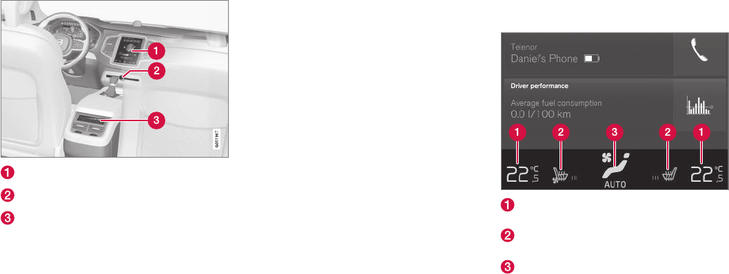
CLIMATE
* Option/accessory, for more information, see Introduction.
178
Climate system controls
Climate system functions are controlled using
buttons on the center console, the center dis-
play and the climate system panel on the rear
side of the tunnel console*.
Overview of climate system controls
Climate system controls in the center display
Defroster buttons on the center console
Climate system panel on the rear side of the
tunnel console*
Related information
•Climate system controls in the center display
(p. 178)
•Climate control system (p. 174)
•Rear climate system controls on the tunnel
console* (p. 180)
•Defrosting windows and mirrors (p. 186)
•Climate system voice commands (p. 119)
Climate system controls in the
center display
All climate system functions can be controlled
from the center display's climate bar and Cli-
mate view.
Climate bar
The most common climate system functions can
be controlled from the climate bar.
Temperature control for the driver and pas-
senger sides.
Control for heated* and ventilated* driver/
passenger seats and heated steering wheel*.
Button for opening Climate view. The graphic
in the button shows the activated climate
system settings.
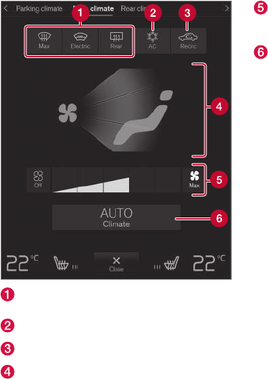
CLIMATE
}}
* Option/accessory, for more information, see Introduction. 179
Climate view
Tap the center button on the climate bar to
access Climate view, which is divided into the fol-
lowing tabs: Main climate, Rear climate* and
Parking climate *Toggle between the tabs by
swiping the screen from left to right and by tap-
ping the respective headings.
Main climate
In addition to the climate bar's functions, other
primary climate system functions can also be
controlled from the Main climate tab.
Max, Electric, Rear: controls for defrosting
windows and door mirrors.
AC: air conditioning controls.
Recirc: recirculation controls.
Air distribution controls.
Blower control for the front seats (also for
the rear seat on models with a 2-zone cli-
mate system).
AUTO: climate system Auto mode.
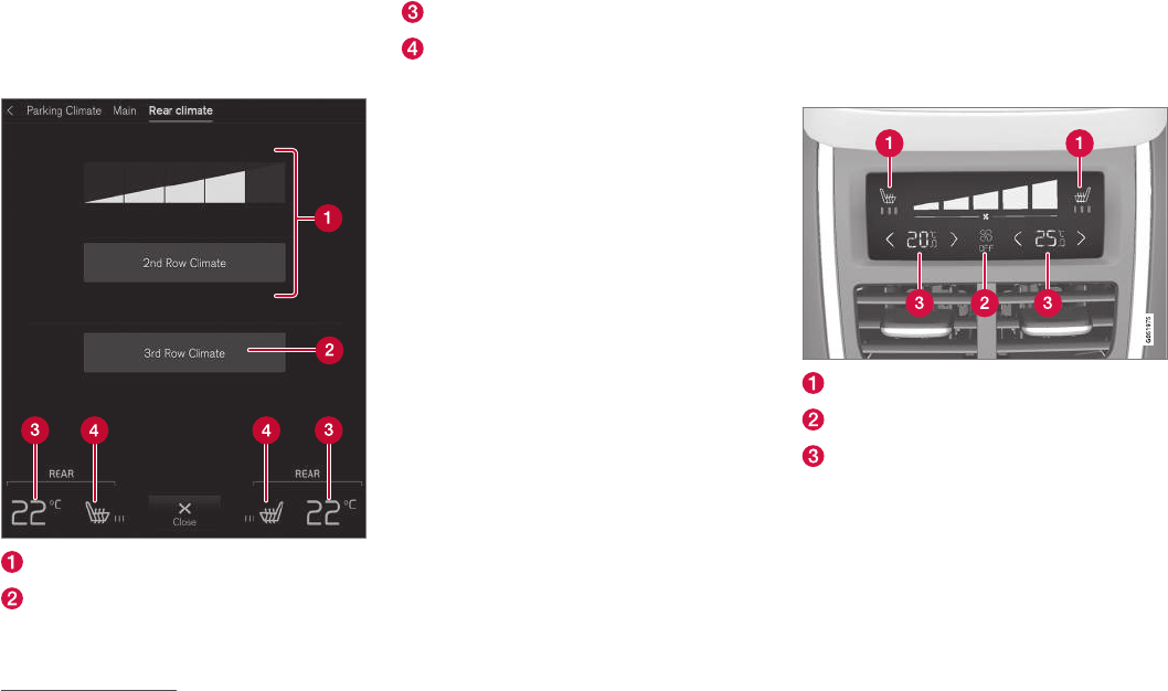
||
CLIMATE
* Option/accessory, for more information, see Introduction.
180
Rear climate*
All of the climate system functions for the rear
seat can be controlled from the Rear climate
tab.
Blower control for the second row of seats.
Blower control for the third row of seats*.
Rear seat temperature control.
Rear seat heating control*.
Parking climate1
All of the parking climate functions can be con-
trolled from the Parking climate tab.
Related information
•Climate system controls (p. 178)
•Defrosting windows and mirrors (p. 186)
•Air conditioning (p. 189)
•Adjusting air distribution (p. 194)
•Setting the temperature (p. 183)
•Setting the blower speed (p. 181)
•Automatic climate control (p. 177)
•Turning steering wheel heating* on and off
(p. 188)
•Turning seat heating* on and off (p. 190)
Rear climate system controls on the
tunnel console*
The rear seat climate system functions are con-
trolled from the rear side of the tunnel console.
Rear seat heating*
Rear seat blower speed
Rear seat temperature control
If the vehicle is not equipped with a climate panel
on the rear side of the tunnel console but also
has heated rear seats*, there will be buttons on
the panel for this function.
Related information
•Climate system controls (p. 178)
•Turning seat heating* on and off (p. 190)
1XC90 T8 Plug-in Hybrid only.
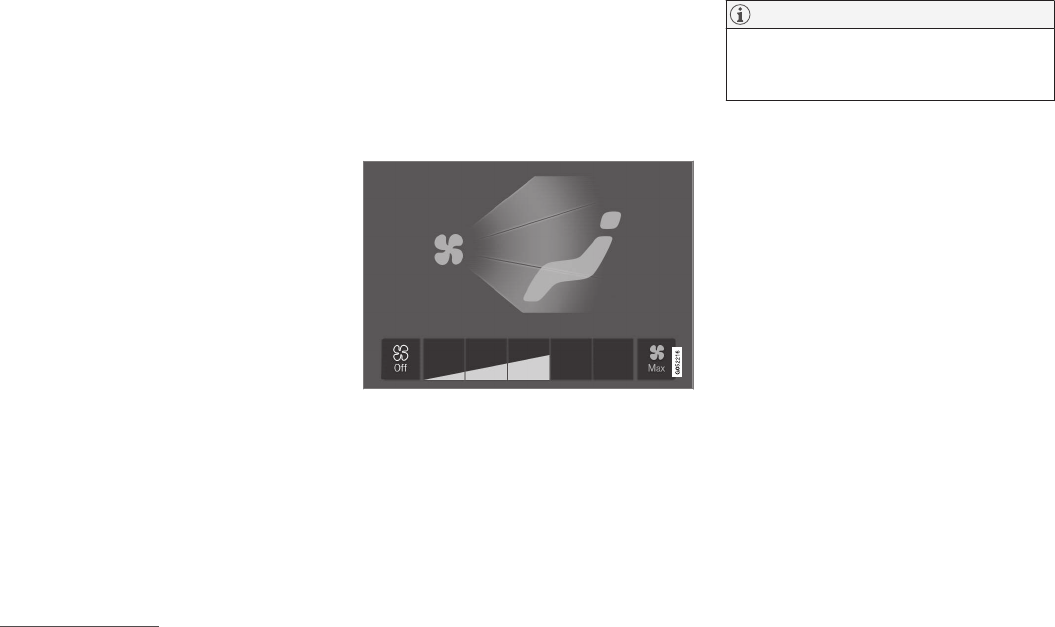
CLIMATE
}}
* Option/accessory, for more information, see Introduction. 181
•Setting the blower speed (p. 181)
•Setting the temperature (p. 183)
Setting the blower speed
The blower can be set to five different automatic
speeds plus Off and Max. In models with the 4-
zone climate system*, blower speed can be set
separately for the front and rear seats.
Setting blower speed for the front
seats4
Blower control buttons in Climate view
1. Go to the center display's Climate view.
2. Tap the desired blower speed: Off, 1–5 or
Max.
> The blower speed will change and the
button for the selected speed will light up.
NOTE
If the blower is turned off completely, the air
conditioning is disengaged, which may result
in fogging on the windows.
4The same setting applies to the rear seats in models with the 2-zone climate system.
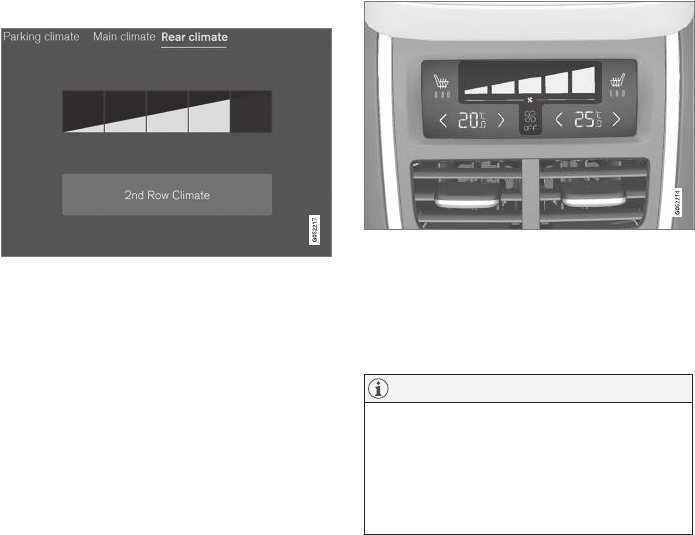
||
CLIMATE
* Option/accessory, for more information, see Introduction.
182
Setting the rear seat blower speed*
From the front seat
Blower control buttons in the Rear climate tab in Cli-
mate view
1. Go to the center display's Climate view.
2. Go to Rear climate.
3. Tap the desired blower speed: 1–5.
The blower can be turned off for the second
and third row of seats* by tapping 2nd row
climate.
The blower speed for the third row of seats *
is the same as for the second row but can be
turned off separately* by tapping 3rd row
climate.
> The blower speed will change and the
button for the selected speed will light up.
From the rear seat
Blower controls on the climate panel on the rear side of
the tunnel console
–Tap the desired blower level: Off or 1–5 on
the climate panel.
> The blower speed will change and the
button for the selected speed will light up.
NOTE
•Blower speed for the rear seat cannot be
set if the front seat blower setting is Off.
•The climate system will adapt air flow
within each set blower speed, which
means that the blower speed may vary
slightly.
Related information
•Climate system controls in the center display
(p. 178)
•Rear climate system controls on the tunnel
console* (p. 180)
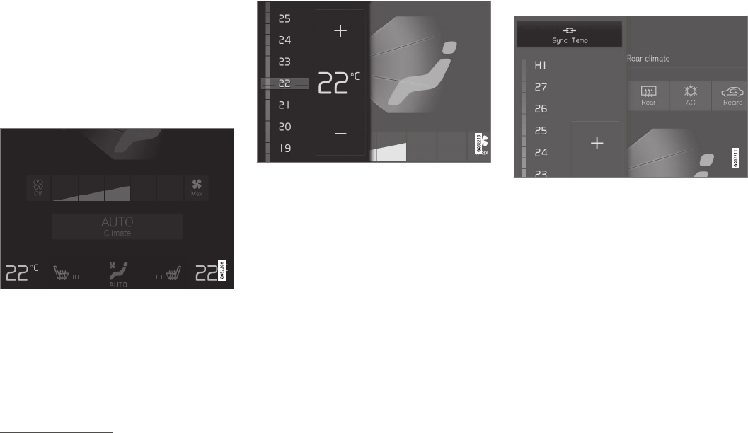
CLIMATE
}}
* Option/accessory, for more information, see Introduction. 183
Setting the temperature5
The temperature can be set separately for the
left and right sides of the passenger compart-
ment and for . In models with the 4-zone climate
system*, it can also be set for the front and rear
seats separately.
Setting the temperature for the front
seats6
Temperature buttons in the climate bar
1. Tap the right or left side temperature button
in the center display's climate bar to open
the control.
Temperature control
2. Set a temperature by:
•dragging the control to the desired tem-
perature or
•tapping +/− to raise/lower the tempera-
ture.
> The temperature will change and the new
temperature will be shown in the button.
Synchronizing the temperature
Synchronization button on the driver's side temperature
control
1. Tap the driver's side temperature button to
open the control.
2. Tap Synchronize temperature .
> The temperature for all of the vehicle's cli-
mate zones will be synchronized with the
one set for the driver's side and the syn-
chronization symbol will be displayed in
the temperature button.
Synchronization can be stopped by tapping
Synchronize temperature again or by chang-
ing the temperature for the passenger's side or
the rear seat*.
5Shown here in Celsius but also applies to Fahrenheit
6The same setting applies to the rear seats in models with the 2-zone climate system.
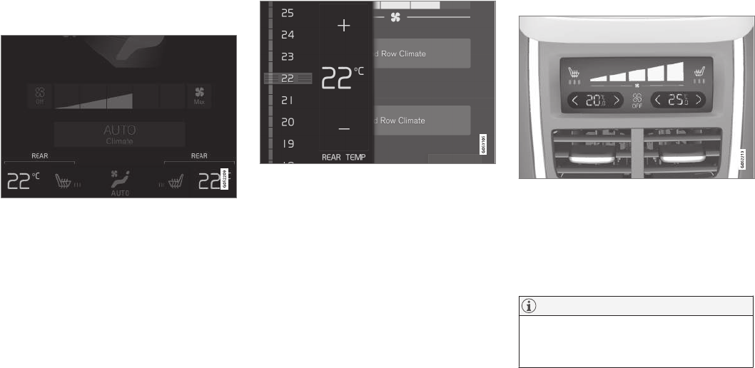
||
CLIMATE
* Option/accessory, for more information, see Introduction.
184
Setting the rear seat temperature*
From the front seat
Temperature buttons in the Rear climate group in Cli-
mate view
1. Go the center display's Climate view.
2. Go to Rear climate.
3. Tap the left or right side temperature buttons
to open the control.
Temperature control
4. Set the temperature by:
•dragging the control to the desired tem-
perature or
•tapping +/− to raise/lower the tempera-
ture.
> The temperature will change and the new
temperature will be shown in the button.
From the rear seat
Temperature controls on the climate panel on the rear
side of the tunnel console
–Tap the left or right side's </>buttons on cli-
mate panel to lower/raise the temperature.
> The temperature will change and the cli-
mate panel screen will show the new tem-
perature.
NOTE
Heating or cooling cannot be speeded up by
selecting a higher/lower temperature than
the actual temperature required.
Related information
•Climate system controls (p. 178)
•Climate system controls in the center display
(p. 178)
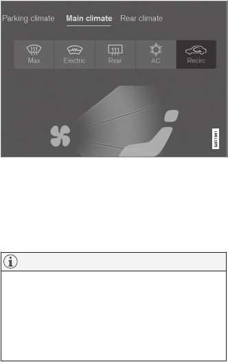
CLIMATE
* Option/accessory, for more information, see Introduction. 185
•Rear climate system controls on the tunnel
console* (p. 180)
•Perceived temperature (p. 174)
Turning recirculation on and off
Recirculation can be used to shut out exhaust
fumes, smoke, etc., from the passenger com-
partment.
Recirculation button in Climate view
1. Go to Climate view in the center display.
2. Press Recirc.
> Recirculation is activated (button lights
up)/deactivated (button is off)
NOTE
•If recirculation is on for too long, there is
a risk of condensation forming on the
insides of the windows, especially in win-
ter.
•Recirculation cannot be deactivated if
max. defroster is being used.
Activating/deactivating the recirculation
timer
With the timer activated, recirculation will switch
off automatically after 20 minutes.
1. Tap Settings in the center display's Top
view.
2. Tap Climate.
3. Activate/deactivate the timer by selecting/
deselecting the box for Recirculation
Timer.
Related information
•Climate system controls in the center display
(p. 178)
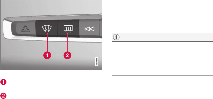
CLIMATE
* Option/accessory, for more information, see Introduction.
186
Defrosting windows and mirrors
The max. defroster, heated windshield* and
heated rear window/door mirror functions are
used to remove ice or condensation.
Using the buttons in the center console
The buttons in the center console offer quick
access to the defroster functions.
On models with the optional heated windshield,
the max. defroster function can only be activated
separately from the Climate view in the center
display.
Center console buttons
Button for the heated windshield* and max.
defroster.
Button for the heated rear window and door
mirrors.
Models without a heated windshield.
–Press button (1).
> Max. defroster is activated (button indica-
tor light on)/deactivated (button indicator
light off).
Models with a heated windshield*.
–Press button (1) repeatedly to access the
function's three levels:
•Activate windshield heating
•Activate windshield heating and max.
defroster
•Deactivated
> The windshield heating is activated (but-
ton indicator light on)/deactivated (button
indicator light off).
NOTE
Max. defroster starts after a slight delay to
avoid a brief increase in blower speed if the
heated windshield function has been deacti-
vated by pressing the button twice in quick
succession.
Heated rear window and door mirrors
–Press button (2).
> Heating for the rear window/door mirrors
is activated (button indicator light on)/
deactivated (button indicator light off).
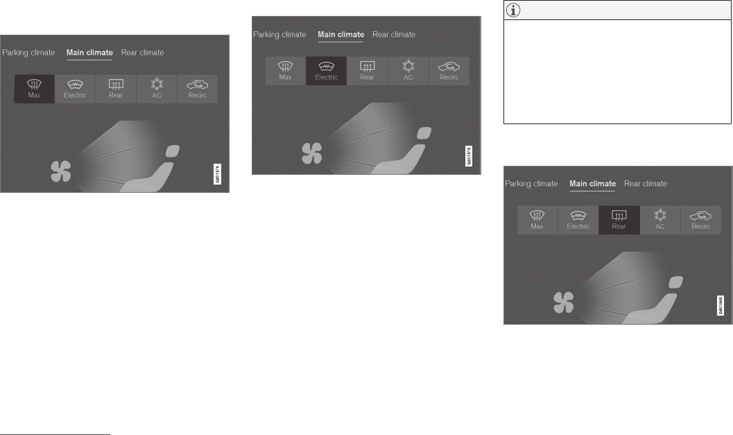
CLIMATE
}}
* Option/accessory, for more information, see Introduction. 187
From the center display's Climate view
Activate/deactivate max. defroster
Max. defroster button in Climate view
1. Go to Climate view in the center display.
2. Tap Max.
> Max. defroster is activated (button lights
up)/deactivated (button is off).
Max. defroster overrides automatic climate
control and recirculation, and activates the
air conditioning, changes blower speed to
57 and the temperature to HI7.
When max. defroster is deactivated, the
climate system returns to the previous
settings.
Activating/deactivating windshield heating*
Windshield heating button in Climate view
1. Go to Climate view in the center display.
2. Tap Electric.
> Windshield heating is activated (button
lights up)/deactivated (button is off).
If windshield heating is activated while the Start/
Stop function has turned off the engine, the
engine will restart.
NOTE
•Triangular areas at the far sides of the
windshield are not heated electrically and
will take slightly longer to defrost/de-ice.
•The heated windshield may affect the
performance/range of e.g., transponders
used to automatically pay highway tolls or
other communication equipment.
Activating/deactivating rear window and
door mirror heating
Rear window/door mirror heating button in Climate view
1. Go to Climate view in the center display.
2. Tap Rear.
> Rear window/door mirror heating is acti-
vated (button lights up)/deactivated (but-
ton is off).
7In models with the 4-zone climate system*, front seats only.
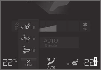
||
CLIMATE
* Option/accessory, for more information, see Introduction.
188
Automatically activating/deactivating
the defrosting function when the engine
is started
The rear window/door mirror/windshield heating*
can be set to start automatically when the engine
is started.
1. Tap Settings in the center display's Top
view and select Climate.
2. Activate/deactivate the respective defroster
functions when the engine is started by
selecting/deselecting the boxes for Auto
Electric Front Defroster and Auto Electric
Rear Defroster.
The heating function will switch off automatically
when the window/mirror is sufficiently warm and
the ice/condensation has disappeared.
Related information
•Climate system controls (p. 178)
•Climate system controls in the center display
(p. 178)
•Defrosting windows and mirrors (p. 186)
•Air conditioning (p. 189)
•Turning recirculation on and off (p. 185)
•Adjusting air distribution (p. 194)
•Setting the blower speed (p. 181)
•Automatic climate control (p. 177)
•Turning front seat ventilation* on and off
(p. 192)
•Turning steering wheel heating* on and off
(p. 188)
Turning steering wheel heating* on
and off
The steering wheel can be heated electrically for
added comfort in cold weather.
Activating/deactivating steering wheel
heating
Buttons for heated steering wheel and seats in the cli-
mate bar
1. Tap the driver side steering wheel and seat
button in the center display's climate bar to
open the steering wheel and seat heating
controls.
If the vehicle is not equipped with the
optional heated or ventilated seats, the but-
ton for steering wheel heating will be directly
accessible in the climate bar.

CLIMATE
}}
* Option/accessory, for more information, see Introduction. 189
2. Tap the steering wheel heating button
repeatedly to select one of four levels: Off,
High, Middle or Low.
> The level changes and is displayed in the
button.
Automatic steering wheel heating
The automatic function starts heating the steer-
ing wheel automatically when the engine is
started if the temperature is sufficiently cold. This
feature can be activated/deactivated.
1. Tap Settings in the center display's Top
view.
2. Tap Climate.
3. Under Auto Steering Wheel Heating
Level, select Off, Low, Middle or High to
activate/deactivate the automatic function.
Related information
•Climate system controls (p. 178)
•Climate system controls in the center display
(p. 178)
•Steering wheel (p. 155)
Air conditioning
The air conditioning cools and dehumidifies the
air in the passenger compartment.
Activating/deactivating the main air
conditioning unit
1. For the air conditioning to function optimally,
close the side windows and laminated panor-
amic roof*.
Air conditioning button in Climate view
2. Go to Climate view in the center display.
3. Tap AC.
> The air conditioning is activated (button
lights up)/deactivated (button is off).
NOTE
•For the air conditioning to function opti-
mally, close the side windows and lamina-
ted panoramic roof*
•The air conditioning cannot be activated
if the blower is set to Off.
Activating/deactivating the air
conditioning unit for the third row
seats*
Air conditioning button in the Rear climate tab in Cli-
mate view
1. Go to Climate view in the center display.
2. Go to Rear climate.
3. Tap 3rd row climate.
> The air conditioning is activated (button
lights up)/deactivated (button is off).
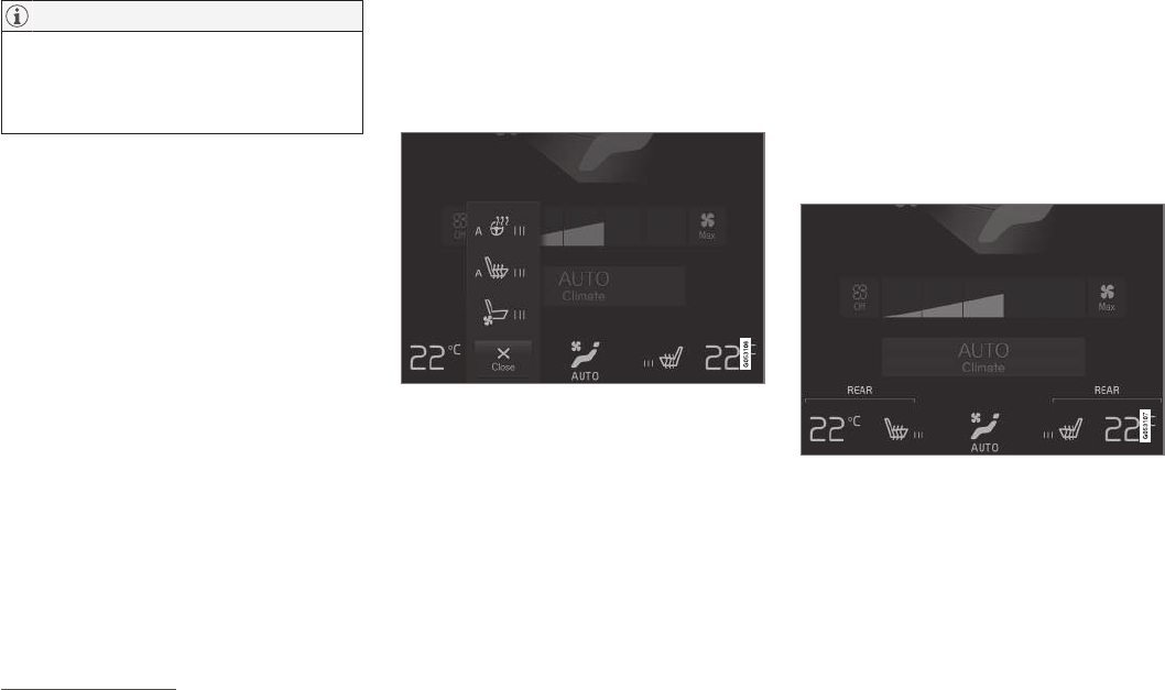
||
CLIMATE
* Option/accessory, for more information, see Introduction.
190
NOTE
Air conditioning for the third row of seats*
cannot be activated if the main air condition-
ing unit or the air conditioning for the second
row of seats* is/are deactivated.
Activating/deactivating the third row air
conditioning when the engine is started
The air conditioning for the optional third row of
seats8 can be set to start automatically when the
engine is started.
1. Tap Settings in the center display's Top
view.
2. Tap Climate.
3. Select Third Row Climate On At Engine
Start to activate/deactivate the air condition-
ing for the third row of seats when the
engine is started.
Related information
•Climate system controls in the center display
(p. 178)
Turning seat heating* on and off
The seats can be heated for added comfort in
cold weather.
Activating/deactivating front seat
heating
Steering wheel and seat buttons in the climate bar
1. Tap the left or right side steering wheel and
seat button in the center display's climate
bar to open the steering wheel and seat
heating controls.
If the vehicle is not equipped with the
optional heated steering wheel or ventilated
seats, the button for seat heating will be
directly accessible in the climate bar.
2. Tap the seat heating button repeatedly to
select one of four levels: Off, High, Middle
or Low.
> The level changes and is displayed in the
button.
Activating/deactivating rear seat
heating
From the front seat*
Temperature buttons for Rear climate in Climate view
1. Tap Settings in the center display's Top
view.
2. Tap Climate.
3. Under Auto Driver Seat Heating Level and
Auto Passenger Seat Heating Level,
select Off, Low, Middle or High to activate/
deactivate and to select the desired level.
8Models with the optional 4-zone climate system only.
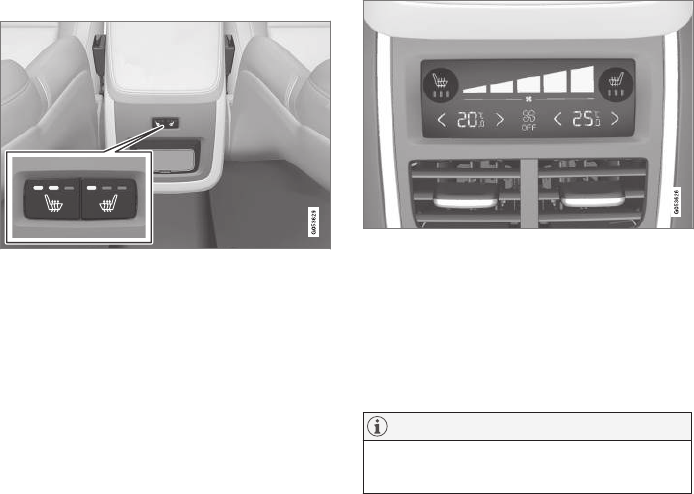
CLIMATE
* Option/accessory, for more information, see Introduction. 191
From the rear seat
With the 2-zone climate system
Seat heating buttons on the climate panel on the rear
side of the tunnel console
–Press repeatedly on the left or right side but-
tons on the climate panel on the rear side of
the tunnel console to select one of four lev-
els: Off, High, Middle or Low.
> The level changes and the indicator lights
in the button display the level.
With the 4-zone climate system*
Seat heating indicator and control on the climate panel
on the rear side of the tunnel console
–Tap repeatedly on the left or right side seat
heating buttons on the climate panel on the
rear side of the tunnel console to select one
of four levels: Off, High, Middle or Low.
> The level changes and is displayed on the
screen in the climate panel.
NOTE
Rear seat heating switches off automatically
after 15 minutes.
Automatically activating/deactivating
the seat heating function when the
engine is started
The seat heating* can be set to start automati-
cally when the engine is started.
The automatic function starts heating the seats
when the ambient temperature is sufficiently cold.
1. Tap Settings in the center display's Top
view.
2. Tap Climate.
3. Under Auto Driver Seat Heating Level and
Auto Passenger Seat Heating Level,
select Off, Low, Middle or High to activate/
deactivate the automatic function and select
a level for the driver's and passenger's seats.
Related information
•Climate system controls (p. 178)
•Climate system controls in the center display
(p. 178)
•Rear climate system controls on the tunnel
console* (p. 180)
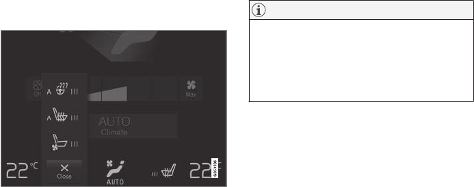
CLIMATE
* Option/accessory, for more information, see Introduction.
192
Turning front seat ventilation* on
and off
Seat ventilation can be used e.g., to help remove
dampness from the seat occupant's clothing.
The ventilation system consists of fans in the
seats and backrests that draw air through the
seat upholstery. The cooling effect increases as
the air in the passenger compartment becomes
cooler. This feature can be activated when the
engine is running and it monitors the seat's tem-
perature, sunlight in the passenger compartment
and the ambient temperature.
Activating/deactivating front seat
ventilation
Steering wheel and seat buttons in the climate bar
1. Tap the left or right side steering wheel and
seat button in the center display's climate
bar to open the steering wheel and seat con-
trols.
If the vehicle is not equipped with the
optional heated steering wheel/seats, the
button for seat ventilation will be directly
accessible in the climate bar.
2. Tap the seat ventilation button repeatedly to
select one of four levels: Off, High, Middle
or Low.
> The level changes and is displayed in the
button.
NOTE
Seat ventilation cannot be started if the tem-
perature in the passenger compartment is too
low.
For use over extended periods, the setting
Low is recommended.
Related information
•Climate system controls (p. 178)
•Climate system controls in the center display
(p. 178)
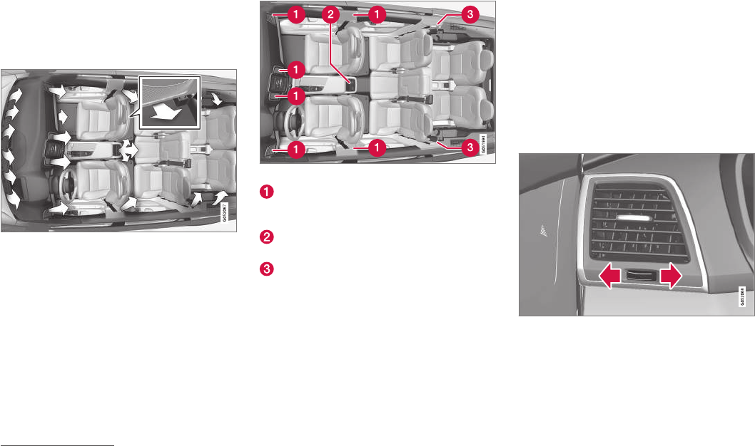
CLIMATE
}}
* Option/accessory, for more information, see Introduction. 193
Air distribution
The incoming air is distributed through a number
of different vents in the passenger compartment.
Air distribution overview
Air distribution with a 4-zone climate system
Adjustable air vents
There are 10* adjustable air vents in the passen-
ger compartment, depending on the climate sys-
tem in the vehicle and the number of seats.
Location of the air vents
2-zone system: four vents on the dashboard
and one on each of the pillars between the
front and rear doors.
4-zone system*: two additional vents on the
rear side of the tunnel console.
4-zone system*: one additional vent on each
of the pillars behind the rear seats.
Related information
•Climate control system (p. 174)
•Adjusting air distribution (p. 194)
•Opening/closing/directing air vents (p. 193)
•Air distribution table (p. 195)
•Automatic climate control (p. 177)
Opening/closing/directing air vents
Some of the passenger compartment air vents
can be open/closed/directed individually.
Direct the dashboard and door pillar outer air
vents toward the side windows to defrost.
Direct the vents into the passenger compartment
to help maintain a comfortable temperature in
warm weather.
Opening/closing air vents
Air vent thumb wheel 9
–Turn the thumb wheel to open/close the air
flow from the vent.
The more of the white line on the thumb
wheel that is visible, the greater the air flow.
9The illustration is generic; its design varies, depending on its location.
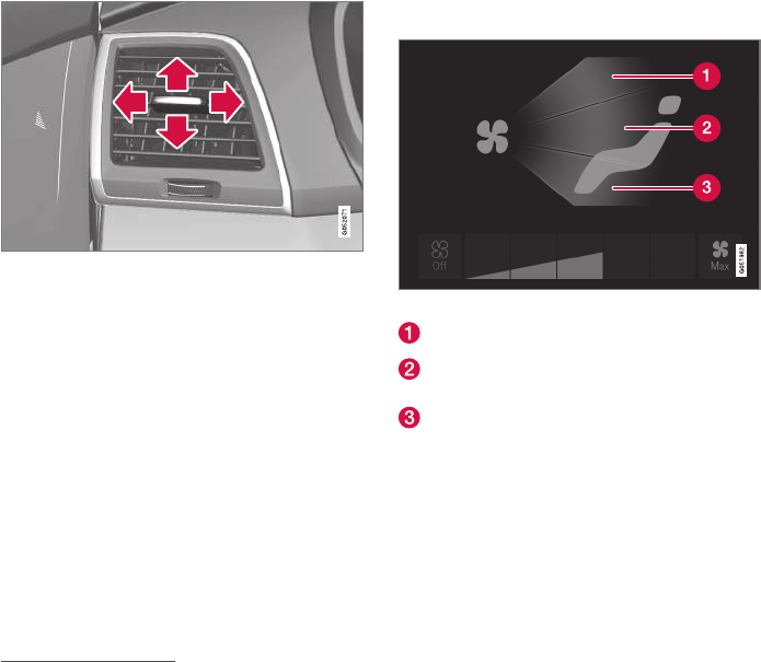
||
CLIMATE
194
Directing air flow
Air flow control 9
–Move the control from side to side or up/
down to direct the flow of air from the vent.
Related information
•Air distribution (p. 193)
•Adjusting air distribution (p. 194)
•Air distribution table (p. 195)
Adjusting air distribution
Air distribution can be adjusted manually.
Air distribution buttons in Climate view
Defrost the windshield
Air vents in the dashboard and center con-
sole
Floor air vents
1. Go to Climate view in the center display.
2. Tap one or more of the air distribution but-
tons to open/close the corresponding air
flow.
> Air distribution changes and the buttons
light up or go out.
Related information
•Air distribution (p. 193)
•Opening/closing/directing air vents (p. 193)
•Air distribution table (p. 195)
•Climate system controls in the center display
(p. 178)
9The illustration is generic; its design varies, depending on its location.

CLIMATE
}}
195
Air distribution table
Air distribution can be adjusted manually.
Air distribution Use
If all air distribution buttons are deselected in manual mode, the climate system
will revert to automatic mode.
Main air flow from the defroster vents, some flow from the other vents. To remove ice and condensation (with moderate
blower speed).
Main air flow from the dashboard vents, some flow from the other vents. For best comfort in hot weather.
Main air flow from the floor vents, some flow from the other vents. For heating/cooling near the floor.

||
CLIMATE
196
Air distribution Use
Main air flow from the defroster and dashboard vents, some flow from the other
vents.
For best comfort in hot and dry weather.
Main air flow from the defroster and floor vents, some flow from the other vents. For best comfort and defrosting in cold or humid con-
ditions.
Main air flow from the dashboard and floor vents, some flow from the other
vents.
For good comfort in sunny, cool weather.
For cooling or heat to the floor.
Main air flow from the defroster, dashboard and floor vents. For cooler air toward the floor in warm weather or
warmer air upward in cold weather.
Related information
•Air distribution (p. 193)
•Opening/closing/directing air vents (p. 193)
•Climate system controls in the center display
(p. 178)
•Adjusting air distribution (p. 194)

LOADING AND STORAGE
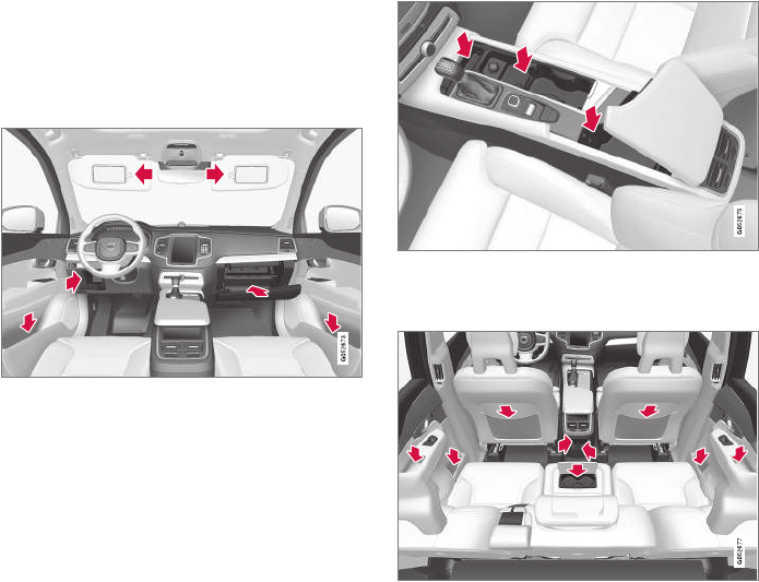
LOADING AND STORAGE
* Option/accessory, for more information, see Introduction.
198
Cargo space
The vehicle has flexible cargo capacity that
makes it possible to load and secure large
objects.
By folding down the backrests in the second and
third rows* of seats, the cargo capacity of the
vehicle increases considerably. To make loading
easier, the rear section of the vehicle can be
raised and lowered using the pneumatic suspen-
sion*. Use the load anchoring eyelets or the gro-
cery bag holder to secure objects and the cargo
compartment cover helps conceal the load.
The spare tire, jack and tools can be found under
the cargo compartment's floor.
Related information
•Loading (p. 205)
•Cargo compartment cover* (p. 211)
•Cargo net (p. 207)
•Grocery bag holder (p. 207)
•Load anchoring eyelets (p. 210)
•Steel cargo grid* (p. 209)
Passenger compartment storage
spaces
The following is an overview of the passenger
compartment and its storage spaces.
Front seats
Storage spaces in the door panel, near the steering
wheel, the glove compartment and the sun visors
Storage spaces, cup holders and 12-volt socket in the
tunnel console
Second row of seats
Storage compartments in the door panels, cupholders in
the center seat's backrest, storage pockets on the rear
side of the front seat backrest, and 12-volt socket on
the rear side of the tunnel console
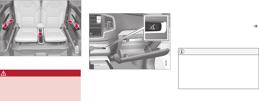
LOADING AND STORAGE
}}
* Option/accessory, for more information, see Introduction. 199
Third row of seats*
Storage space and cup holder in the side panel and the
storage space between the seats
WARNING
Always stow loose items such as cell phones,
cameras, remote controls, etc. in the glove
compartment or other storage spaces to help
keep them from becoming projectiles in the
event of sudden braking, etc.
Related information
•Tunnel console (p. 200)
•Using the glove compartment (p. 199)
•Electrical sockets (p. 202)
•Sun visors (p. 201)
Using the glove compartment
The glove compartment provides a lockable stor-
age compartment for small items.
The glove compartment and opening button on the cen-
ter console
The owner's manual and maps can be kept here.
There are also holders for pens on the inside of
the glove compartment door.
Opening the glove compartment
–Press the glove compartment button on the
center console.
> The glove compartment door will open.
Locking/unlocking the glove
compartment
The glove compartment can be locked when e.g.,
the vehicle is in a workshop for service, etc. When
the private locking function is activated, the tail-
gate is also locked.
Locking the glove compartment
1. This can be done from the center display's
Function or Settings view:
•Go to Function view and tap Private
locking unlocked.
•Go to Settings view and select My Car
Locking and Unlocking Feedback. Tap
the Private Locking box.
> A pop-up window will appear.
NOTE
A security code has to be selected the first
time this function is used. This code is used
to reset the function if an attempt has been
made to deactivate private locking using an
incorrect code.
Keep this code in a safe place.
2. Enter the code to be used to unlock the
glove compartment and tap Confirm.
> The glove compartment will be locked.
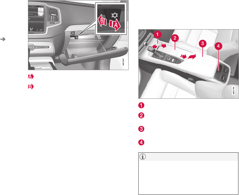
||
LOADING AND STORAGE
* Option/accessory, for more information, see Introduction.
200
Unlocking the glove compartment
1. This function can be deactivated from the
center display's Function or Settings view:
•Go to Function view and tap Private
locking locked.
•Go to settings and select My Car
Locking and Unlocking Feedback.
Deselect the Private Locking box.
> A pop-up window will appear.
2. Specify the code to be used to lock the glove
compartment and tap Confirm.
> The glove compartment will be unlocked.
Using the glove compartment as a
cooler*
The glove compartment can be used to cool
drinks or food and the cooling feature functions
when the climate system is active (i.e., when the
ignition is in mode II or when the engine is run-
ning).
Cooling activated
Cooling deactivated
–Activate/deactivate cooling by moving the
control as far as possible toward the passen-
ger compartment/glove compartment.
Related information
•Passenger compartment storage spaces
(p. 198)
•Locking/unlocking the tailgate (p. 235)
Tunnel console
The tunnel console, located between the front
seats, contains a 12-volt electrical socket, cup
holders and storage spaces, etc.
Storage space
Storage space with cup holders for the driver
and passenger and a 12-volt socket
Storage space and USB/AUX sockets under
the armrest
Climate control panel for the rear seats*
NOTE
One of the alarm sensors, which is sensitive
to metallic objects, is located under the tunnel
console cup holders. Avoid leaving coins,
keys, etc., in the cup holders because they
may inadvertently trigger the alarm.
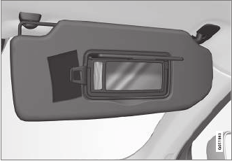
LOADING AND STORAGE
* Option/accessory, for more information, see Introduction. 201
Related information
•Passenger compartment storage spaces
(p. 198)
•Electrical sockets (p. 202)
•Alarm (p. 216)
•Rear climate system controls on the tunnel
console* (p. 180)
Sun visors
There are vanity mirrors with card holders on the
upper sides of the sun visors.
Lighted vanity mirror and card holder
The vanity mirror lighting comes on when the mir-
ror is opened.
The vanity mirror's frame has a holder for e.g., a
card or ticket.
Related information
•Passenger compartment storage spaces
(p. 198)
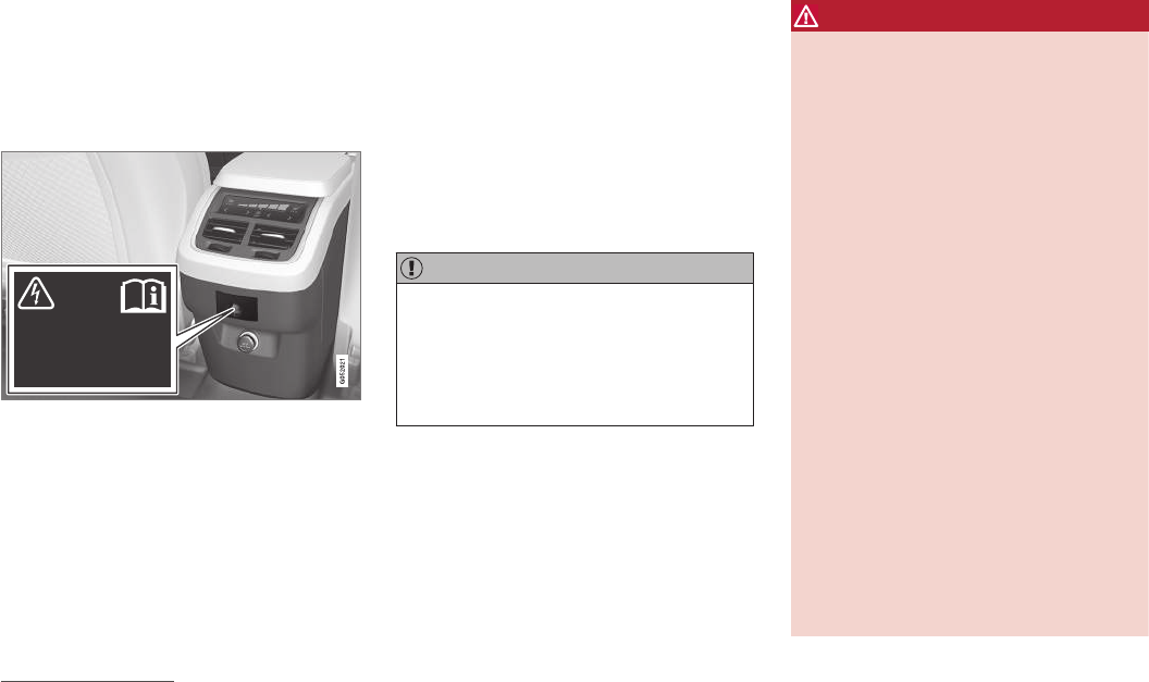
LOADING AND STORAGE
* Option/accessory, for more information, see Introduction.
202
Electrical sockets
There are two 12-volt sockets in the tunnel con-
sole, a 120-volt socket on the rear side of the
tunnel console, and one 12-volt socket in the
cargo area*.
120-volt socket in the tunnel console1
120-volt socket in the tunnel console for the second
row of seats
This socket is intended for 120-volt devices such
as laptops, chargers, etc.
The max. current provided is 150W.
Using the socket
1. Pull down the cover over the socket and plug
in the device.
> The socket's indicator light will indicate its
status. The socket can only provide elec-
trical current when the light is green.
2. Disconnect the device by pulling its plug, not
its cord.
Pull up the cover over the socket when it is not in
use.
CAUTION
•Do not connect devices with large or
heavy plugs that could come loose while
driving.
•Do not use devices that can cause inter-
ference with the vehicle's radio receiver
or electrical system.
WARNING
•Be sure to place any devices connected
to the socket safely so that they do not
become projectiles in the event of a sud-
den stop and injure the occupants of the
vehicle.
•Be aware that connected devices may
generate heat and become very hot.
•Only connect devices that function cor-
rectly and are free from defects. These
devices should be intended for use in a
120-volt, 60Hz socket with a plug
intended for the socket in the vehicle and
be UL-approved (or the equivalent
thereof).
•Never let the device, its plug or the
socket itself come in contact with fluids
of any kind. Never touch or use the
socket if it appears to be damaged or
wet.
•Never connect multiple plugs, adapters or
extension cords to the socket. This could
override the socket's safety functions.
•Never let children play or tamper with the
socket, or attempt to insert any objects
into it. Never leave children unattended in
the vehicle when the socket is active.
•Never try to modify or repair the 120-volt
socket. This should only be done by a
1Certain models only.

LOADING AND STORAGE
}}
203
trained and qualified Volvo service techni-
cian.
Failure to follow the points above could result
in electrical shock and/or serious injury.
Status indication
An LED (Light Emitting Diode) on the socket
indicates its status:
Status indicator light Socket status Action
Steady green light The socket is providing current to a connected device. None.
Flashing orange light The socket's voltage converter is too hot (the connected device draws too much
current, etc. or the temperature in the passenger compartment is very high).
Unplug the device, let the converter cool down
and plug in the device again.
The connected device draws too much current (constantly or currently) or is not
functioning properly.
None. The device should not be plugged into the
socket.
Indicator light off The socket has not detected a plugged in device. Be sure the device is correctly plugged into the
socket.
The socket is not active. Put the vehicle's ignition in at least mode I.
The socket has been active but has been deactivated. Start the engine and/or charge the start battery.
If a problem persists, have the socket checked by
a trained and qualified Volvo service technician.
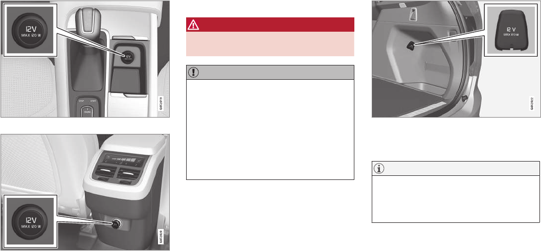
||
LOADING AND STORAGE
204
12-volt socket in the tunnel console
12-volt socket in the tunnel console for the front seats
12-volt socket in the tunnel console for the second row
of seats
The electrical sockets can be used for 12-volt
devices such as monitors, MP3 players and cell
phones. For the sockets to provide electrical cur-
rent, the ignition must be in at least mode I.
WARNING
Always keep the sockets covered when not in
use.
CAUTION
Max. current provided is 10 A (120 W) if one
socket is used at a time. If both of the sock-
ets in the tunnel console are used at the
same time, the max. current provided per
socket is 7.5 A (90 W)
If a tire sealing system's compressor is being
used, no other device should be connected to
any of the other sockets while the compres-
sor is operating.
12-volt socket in the cargo area
12-volt socket in the cargo area
Fold down the cover to access the socket. Max.
current provided is 10 A (120 W).
NOTE
The 12-volt socket in the cargo area provides
electrical current even when the ignition is
switched off. Using the socket while the
engine is not running will drain the battery.
Related information
•Passenger compartment storage spaces
(p. 198)
•Ignition modes (p. 360)
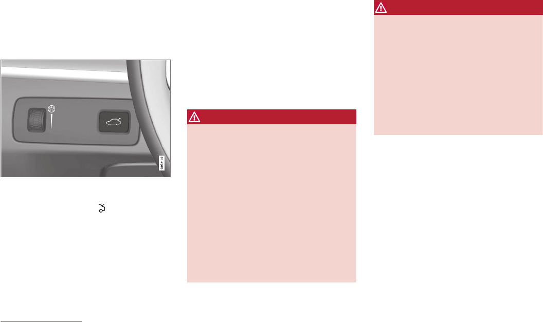
LOADING AND STORAGE
}}
* Option/accessory, for more information, see Introduction. 205
Loading
The load carrying capacity of your vehicle is
determined by factors such as the number of
passengers, the amount of cargo, the weight of
any accessories that may be installed, etc.
Tailgate opening button on the lighting panel
Open the tailgate by pressing the button on the
lighting panel, pressing the button on the
remote key or by using the optional foot move-
ment sensor under the rear bumper.
Loading recommendations
•Load objects in the cargo compartment
against the backrest whenever possible.
•If the backrests of the second row seats are
folded down, they should not be in contact
with the front seat backrests. This could
impede the function of the Whiplash
Protection System (WHIPS).
•Unstable loads can be secured to the load
anchoring eyelets with straps or web lash-
ings to help keep them from shifting.
•Stop the engine and apply the parking brake
when loading or unloading long objects. The
gear selector can be knocked out of position
by long loads, which could set the vehicle in
motion.
WARNING
•Stop the engine, put the gear selector in
P, and apply the parking brake when
loading or unloading long objects.
•The vehicle's driving characteristics may
change depending on the weight and dis-
tribution of the load.
•A 44-pound (20 kg) object produces a
force of 2,200 pounds (1,000 kg) in a
head-on collision at 30 mph (50 km/h).
•The cargo area and rear seat should not
be loaded to a level higher than 2 in.
(5 cm) below the upper edge of the rear
side windows. Objects placed higher than
this level could impede the function of
the Inflatable Curtain.
WARNING
•Cover sharp edges on long loads to help
prevent injury to occupants. Secure the
load to help prevent shifting during sud-
den stops.
•Always secure large and heavy objects
with a seat belt or cargo retaining straps.
•Always secure the load to help prevent it
from moving in the event of sudden stops.
•Switch off the engine, apply the parking
brake and put the gear selector in P
when loading and unloading the vehicle.
Raising/lowering the rear-end of the
vehicle*
Using the buttons on the read edge of the cargo
compartment, the rear-end of the vehicle (the
level of the cargo compartment floor) can be
raised or lowered for easier loading or to make
attaching a trailer2 simpler.
2An accessory trailer hitch can be purchased from a Volvo retailer.
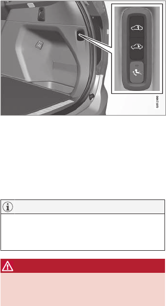
||
LOADING AND STORAGE
* Option/accessory, for more information, see Introduction.
206
Level control buttons on the rear edge of the cargo
compartment
The level control consists of two buttons: one to
raise and one to lower the rear-end of the vehi-
cle.
Press and hold the respective buttons until the
desired level has been reached.
NOTE
The level cannot be adjusted if a door or the
hood are open (this does not apply to the tail-
gate).
WARNING
Be sure that the entire area under the vehicle
is completely unobstructed before lowering
the level.
Extra loading space
The rear seat backrests can be folded down to
added cargo space or for transporting long
objects.
Roof loads
Load carriers are available as Volvo accessories.
Observe the following points when in use:
•To avoid damaging your vehicle and to
achieve maximum safety when driving, we
recommend using the load carriers that Volvo
has developed especially for your vehicle.
•Volvo-approved removable roof racks are
designed to carry the maximum allowable
roof load for this vehicle (see the article
"Weights" for specific information).
•Never exceed the rack manufacturer's weigh
limits.
•Avoid single-point loads. Distribute loads
evenly.
•Place heavier cargo at the bottom of the
load.
•Secure the cargo correctly with appropriate
tie-down equipment.
•Check periodically that the load carriers and
load are properly secured.
•Remember that the vehicle's center of gravity
and handling change when you carry a load
on the roof.
•The vehicle's wind resistance and fuel con-
sumption will increase with the size of the
load.
•Drive smoothly. Avoid rapid starts, fast cor-
nering and hard braking.
See the article "Weights" for information about
the maximum permissible load that can be trans-
ported on the roof.
Related information
•Folding the second row backrests (p. 168)
•Folding the third row* backrests (p. 171)
•Weights (p. 549)
•Cargo net (p. 207)
•Cargo compartment cover* (p. 211)
•Load anchoring eyelets (p. 210)
•Whiplash protection system (p. 59)
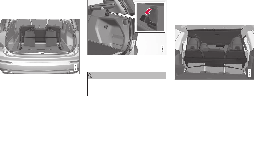
LOADING AND STORAGE
}}
* Option/accessory, for more information, see Introduction. 207
Grocery bag holder
The grocery bag holders (hooks) and elastic
strap help keep shopping bags in place.
Under the cargo compartment floor3
There are two grocery bag holders and an elastic
strap4 in the hatch that is part of the cargo area
floor. The strap can be attached in four positions.
Open the hatch to access the grocery bag hold-
ers and attach the elastic strap. Grocery bags
with handles can also be hung on the hooks.
On the sides of the cargo compartment
There are also two fold-out holders in the side
panels, one on each side.
CAUTION
The grocery bag holders (hooks) are only
intended to hold weights less than approx.
11 lbs (5 kg).
Related information
•Cargo net (p. 207)
•Steel cargo grid* (p. 209)
•Cargo compartment cover* (p. 211)
Cargo net
The cargo net helps protect passengers from
objects in the cargo compartment in the event of
a sudden stop or hard braking.
The cargo net is attached at four points.
Cargo net
The cargo net can be mounted in two positions:
•Rear mounting: behind the second row seats'
backrests.
•Front mounting: behind the front seats' back-
rests.
35-seat models only.
4Can be replaced by ordering a new one from a Volvo retailer.

||
LOADING AND STORAGE
208
WARNING
•Objects in the cargo compartment should
always be securely anchored.
•The nets upper hooks must be securely
inserted into the ceiling mounting points
and the lower spring hooks must be
securely hooked onto the cargo anchor-
ing eyelets.
•A damaged net must never be used.
Attaching
1. Fold out the cargo net and fold out the upper
rod. Be sure it locks in position.
2. Insert one of the net's upper hooks into the
front or rear ceiling mounting point with the
net's lower straps' locks facing you.
3. Insert the other upper hook into the ceiling
mounting point on the opposite side. It is
spring-loaded to make mounting easier.
Press each of the hooks as far forward into
the respective mounting points as possible.
Rear mounting
4. Rear mounting: with the upper hooks
inserted into the rear ceiling mounting points,
hook the lower straps through the load
anchoring eyelets on the floor of the cargo
compartment as show in the illustration.
Front mounting
Front mounting: with the upper hooks
inserted into the front ceiling mounting
points, hook the lower straps through the
eyelets on the front seat rails as shown in the
illustration. Attaching the net is easier if the
front seat backrests are upright and the seats
are moved slightly forward.
Adjust the front seats so that they only touch
the net but do not apply pressure to it.
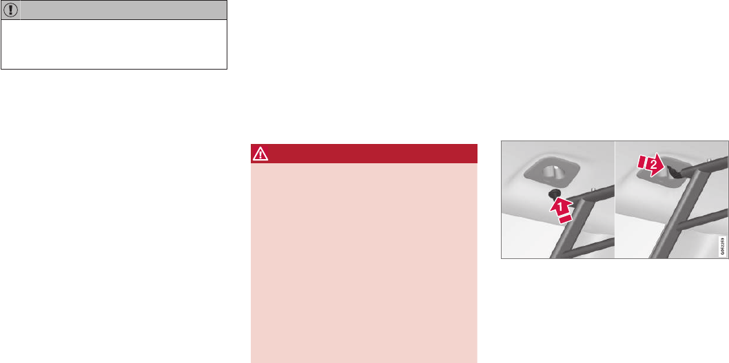
LOADING AND STORAGE
}}
* Option/accessory, for more information, see Introduction. 209
CAUTION
Pressure from the front seats against the
cargo net could damage the net and/or its
brackets.
5. Pull the lower straps taut.
Removing and storing
1. Reduce tension on the net by pressing the
button on the lower straps' respective locks
and allow some slack on both sides.
2. Press in the catches and release both of the
straps' hooks.
3. Remove the upper hooks from the ceiling
mounting points.
4. Press the red button on the upper rod to
allow it to fold.
5. Fold and roll up the net.
Store the net under the cargo compartment floor.
Related information
•Cargo compartment cover* (p. 211)
•Load anchoring eyelets (p. 210)
•Steel cargo grid* (p. 209)
•Loading (p. 205)
Steel cargo grid*
Your vehicle can be equipped with a steel grid
that helps prevent objects in the cargo area from
moving forward into the passenger compart-
ment.
The steel grid is made up of the grid itself and
two separate mounting brackets. Each of the
brackets has a screw cover and there are two
plastic sleeves for the grid.
WARNING
•No one should ever be allowed to remain
in the cargo compartment when the vehi-
cle is moving.
•The steel grid may only be used in the
rear position described in this article. The
ceiling attachment points above the front
seats are not intended to anchor the
steel grid.
•The third row of seats (7-seat models*
only): these seats must be folded down
when the steel grid is mounted in the
vehicle.
•After being mounted, be sure that the
steel grid is securely anchored in place.
Mounting
1. Fold down the rear seats (second row of
seats in 7-seat models) and lift in the steel
grid through one of the rear doors or the tail-
gate. The curved (convex) side of the grid
should face toward the cargo compartment
and the hooks on each side of the grid
should face upward. The mounting brackets
and plastic sleeves are not needed in this
step.
2. Press one of the grid's hooks into the larger
part of the opening in the ceiling attachment
point (1) as shown in the illustration.
3. Grasp the grid near the hook and move it
toward the smaller opening (2).
> This secures the hook in the attachment
point.
4. Repeat steps 2 and 3 for the hook on the
opposite side of the grid.
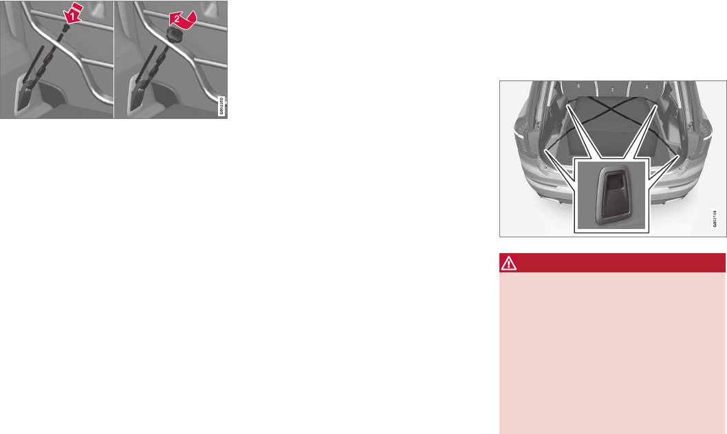
||
LOADING AND STORAGE
* Option/accessory, for more information, see Introduction.
210
5. Attach the mounting bracket's hook through
the cargo anchoring eyelet near the floor of
the cargo compartment and insert the threa-
ded section of the bracket through the grid's
lower attachment hole (1).
6. Slide the plastic sleeve onto the threaded
section of the of the mounting bracket with
the sleeve's flange turned upward and press
it down through the hole. Screw the screw
cover into place until its underside is approx.
0.2 in. (5 mm) from the grid (2).
7. Repeat steps 5 and 6 for the opposite side.
8. Center the grid and tighten both mounting
brackets alternately until the grid is held
securely in place.
Removing
Perform the steps above in reverse order. The
hooks can be removed before the plastic sleeves
are removed from the holes in the grid.
Related information
•Cargo net (p. 207)
•Cargo compartment cover* (p. 211)
•Load anchoring eyelets (p. 210)
•Loading (p. 205)
Load anchoring eyelets
The eyelets in the cargo compartment can be
folded out to secure objects with straps, a net,
etc.
Load anchoring eyelets
WARNING
•Cover sharp edges on long loads to help
prevent injury to occupants. Secure the
load to help prevent shifting during sud-
den stops.
•Always secure large and heavy objects
with a seat belt or cargo retaining straps.
•Always secure the load to help prevent it
from moving in the event of sudden stops.
•Switch off the engine, apply the parking
brake and put the gear selector in P
when loading and unloading the vehicle.
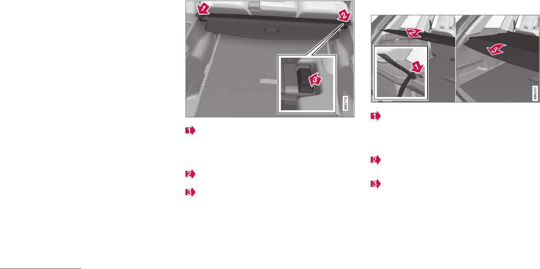
LOADING AND STORAGE
}}
* Option/accessory, for more information, see Introduction. 211
Related information
•Loading (p. 205)
Cargo compartment cover*
The cover can be used to conceal objects in the
cargo area.
Installing the cover5
With the cover retracted, press the end piece
on one side of the cargo area cover into the
retaining bracket in the side panel of the
cargo area.
Do the same on the opposite side.
Press both sides of the cover, one at a time,
until they click into place.
> The red mark will no longer be visible.
Check that both ends of the cover are
securely locked in place.
Use
The cover can be used in two positions: fully
open to completely cover the cargo compartment
or partially retracted to make it easier to reach
farther into the cargo compartment.
Fully open
Third row seats, 7-seat models*: hang the
seat belt latches in the hooks provided in the
side panels. For 5-seat models, see the fol-
lowing step.
With the cover retracted, grasp its handle
and pull it out completely.
Press the attaching pins on the rear corners
of the cover into the grooves in the side pan-
els and release the cover.
> The cover is now fixed in the fully open
position.
5XC90 Excellence only: the cover is permanently mounted and cannot be retracted or removed.
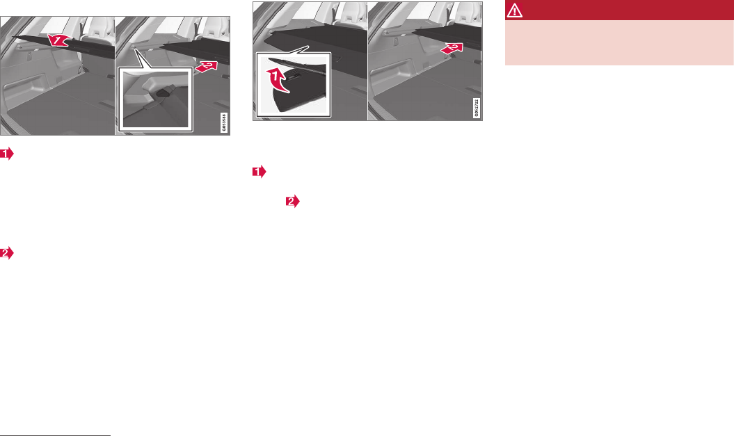
||
LOADING AND STORAGE
212
Partially retracted
With the cover retracted, grasp its handle
and pull it so that it is above the cargo com-
partment's side panels until it is fully open.
Press the attaching pins on the rear corners
of the cover into the grooves in the side pan-
els. If the cover is already fully open see the
next step.
With the cover completely pulled out, press it
upward lightly and allow it to retract slowly.
> Allow the cover to retract until it stops in
the partially retracted position.
If you are holding something in one of your
hands:
From the fully open position, push the cover's
handle slightly upward with e.g., your elbow.
> The cover will close until it reaches the
partially retracted position.
To fully open the cover from the partially open
position:
1. Grasp the handle and pull out the cover to
the fully open position.
2. Let the cover retract slightly and press the
handle slightly downward.
> The cover will be secured n the fully open
position.
Avoid placing any objects on the cover when it is
open.
WARNING
7-seat models: remove the cargo compart-
ment cover completely from the vehicle if one
or both of the third row seats will be occupied.
Retracting the cover5
From the fully open position:
–Lift the cover's handle and pull it rearward
slightly to release the attaching pins from
their grooves. Allow the cover to retract.
From the partially retracted position:
–Grasp the handle and lift it slightly to release
the attaching pins from their grooves. Pull
the cover to the fully open position.
> Allow the cover to retract completely.
Removing the cover5
1. With the cover retracted, press the button on
one of the cover's ends and lift out that end.
2. For 7-seat models: Release the seat belt
latches from the hooks in the side panels.
For 5-seat models, see the following step.
3. Carefully lift the cover up/out.
> The other end will release automatically.
Lift the cover out of the cargo compart-
ment.
5XC90 Excellence only: the cover is permanently mounted and cannot be retracted or removed.


LOCKS AND ALARM

LOCKS AND ALARM
* Option/accessory, for more information, see Introduction.
216
Locks and remote keys
The vehicle can be locked and unlocked in vari-
ous ways and there are several types of remote
keys that can be used.
Locking/unlocking/opening/closing
The vehicle can be locked/unlocked from the
passenger compartment, using the buttons on
the remote key or by using the optional Passive
Entry system where it is only necessary to have a
key in your possession to lock or unlock the
doors.
On models equipped with a power tailgate*, the
tailgate can be opened/closed by moving your
foot under a sensor* beneath the rear bumper.
If for any reason a remote key does not function
properly, it may be necessary to replace its bat-
teries but the vehicle can always be locked or
unlocked manually using the remote key's
detachable key blade.
Remote key
The remote key does not have to be physically
handled in order to start the engine because the
vehicle is equipped with the standard Passive
Start system (the key only needs to be in the
front part of the passenger compartment). If the
vehicle is equipped with the optional Passive
Entry system that enables keyless entry and start,
the key can be anywhere in the vehicle when the
engine is started.
Models with Passive Entry* also have an extra,
smaller key without buttons called a Key Tag.
Additional keys can be ordered from a Volvo
retailer.
Related information
•Immobilizer (p. 221)
•Alarm (p. 216)
•Child safety locks (p. 218)
•Remote key (p. 225)
•Foot movement tailgate operation* (p. 228)
•Locking/unlocking from inside the vehicle
(p. 232)
•Locking/unlocking from outside the vehicle
(p. 233)
•Locking/unlocking the tailgate (p. 235)
•Starting the engine (p. 362)
Alarm
The alarm system provides a warning if an
attempt is made to break into the vehicle.
The following conditions will trigger the alarm:
•a door/hood/tailgate are opened
•the battery is disconnected
•the alarm siren is disconnected
If a problem is detected in the alarm system, a
message will be displayed in the instrument
panel.
Do not attempt to repair any of the components
in the alarm system yourself; this could affect the
insurance policy on the vehicle. Contact a trained
and qualified Volvo service technician.
NOTE
One of the alarm sensors, which is sensitive
to metallic objects, is located under the tunnel
console cup holders. Avoid leaving coins,
keys, etc., in the cup holders because they
may inadvertently trigger the alarm.
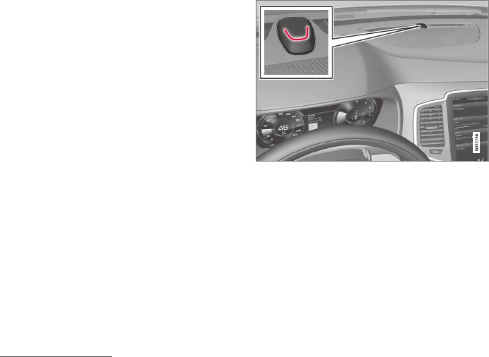
LOCKS AND ALARM
* Option/accessory, for more information, see Introduction. 217
Arming the alarm
–Lock the vehicle by pressing the remote
key's lock button, pressing the outer indenta-
tion for locking on one of the door handles1
or by pressing the tailgate's rubberized pres-
sure plate1.
If the vehicle is equipped with a power tail-
gate*, the button on the lower edge of the
tailgate can also be used to lock the vehicle
and arm the alarm.
Disarming the alarm
–Unlock the vehicle by pressing the remote
key's unlock button, pressing the pressure-
sensitive area on the inside of one of the
door handles1 or by pressing the tailgate's
rubberized pressure plate1.
Turning off a triggered (sounding)
alarm
–Press the remote key's unlock button or put
the ignition in mode I by turning the start
knob to START and releasing it.
Alarm signals
The following occurs if the alarm has been trig-
gered:
•A siren will sound for 30 seconds or until the
alarm is turned off
•All turn signals flash for 5 minutes or until
the alarm is turned off
If the door that triggered the alarm is left open,
the alarm cycle will be repeated 10 times.
Alarm indicator
A red indicator light on the upper side of the
dashboard shows the alarm's status:
•Indicator off: the alarm is disarmed
•Indicator flashes once every two seconds:
the alarm is armed
•Indicator flashes quickly after the alarm has
been disarmed until the ignition has been put
in mode I (turn the start knob to START and
release it): the alarm has been triggered
Related information
•Automatically arming/disarming the alarm
(p. 218)
•Deactivating the alarm without a functioning
remote key (p. 218)
1Models withe the optional Passive Entry only.
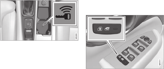
LOCKS AND ALARM
* Option/accessory, for more information, see Introduction.
218
Automatically arming/disarming the
alarm
Automatically arming the alarm helps prevent
inadvertently leaving the vehicle without alarm
protection.
If the vehicle has been unlocked with the remote
key (and the alarm has been disarmed) but no
door or the tailgate has been opened within
2 minutes, the vehicle will automatically relock
and the alarm will re-arm.
In certain markets, the alarm will be re-armed
automatically after a slight delay after the driver's
door has been opened and closed without being
locked.
Related information
•Alarm (p. 216)
•Deactivating the alarm without a functioning
remote key (p. 218)
Deactivating the alarm without a
functioning remote key
If the remote key is not functioning properly, the
alarm can be turned off and the vehicle can be
started as follows:
1. Unlock and open the driver's door with the
detachable key blade.
> This will trigger the alarm.
Location of the back-up key reader in the cup holder
2. Place the remote key on the back-up key
reader in the tunnel console's cup holder.
3. Turn the start knob to START and release it.
> The alarm will turn off.
Related information
•Alarm (p. 216)
•Detachable key blade (p. 227)
•Starting the engine (p. 362)
•Automatically arming/disarming the alarm
(p. 218)
Child safety locks
Child safety locks help prevent children from
inadvertently opening one of the rear doors from
inside the vehicle.
Electronic* activation/deactivation
The electronic child safety locks can be acti-
vated/deactivated as long as the ignition is not
completely switched off and this can be done for
up to two minutes after the engine has been
switched off if no door has been opened.
To activate:
Child safety lock button on the driver door control panel
1. Switch on the ignition or start the engine.
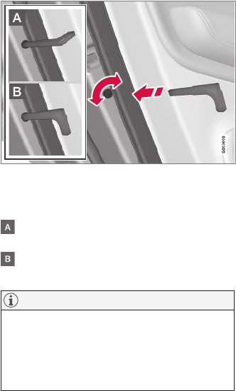
LOCKS AND ALARM
219
2. Press the button on the driver's door control
panel.
>Rear child lock Activated will be dis-
played in the instrument panel and the
indicator light in the button will illuminate
to show that the child safety locking func-
tion is activated.
While the child safety locks are activated:
•the rear door windows can only be opened
from the driver door control panel
•the rear doors cannot be opened from the
inside
To deactivate:
–Press the button in the driver door control
panel.
>Rear child lock Deactivated will be dis-
played in the instrument panel and the
indicator light in the button will go out to
show that the child safety locking function
is deactivated.
When the ignition is switched off, the current set-
ting for the child safety locks will be stored. If the
locks were activated at that time, they will con-
tinue to be activated when the ignition is
switched on again.
Manual activation/deactivation
Manual child safety locks in the rear doors
–Use the detachable key blade in the remote
key to adjust these controls.
The rear doors can only be opened from the
outside.
The rear doors can be opened from the
inside or the outside.
NOTE
•Each control on the respective doors
control that door only, not both doors.
•There are no manual child safety locks on
models equipped with the electronic
option.
Related information
•Detachable key blade (p. 227)
•Ignition modes (p. 360)
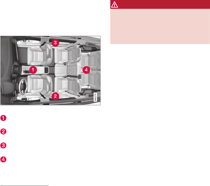
LOCKS AND ALARM
* Option/accessory, for more information, see Introduction.
220
Antenna locations for the start and
lock system
The vehicle is equipped with a keyless2 start and
lock system that requires a number of antennas
located at various points in the vehicle.
Location of the antennas
Under the cup holders in the front section of
the tunnel console
In the upper front section of the driver side
rear door2
In the upper front section of the passenger
side rear door2
In the center of the rear seat backrest2,3
WARNING
People with implanted pacemakers should not
allow the pacemaker to come closer than
9 inches (22 cm) to any of the Passive Entry
system's antennas. This is to help prevent
interference between the pacemaker and the
Passive Entry system.
Related information
•Remote key (p. 225)
•Remote key's range (p. 225)
Start and lock system type
designations
The following information contains type designa-
tions for the start and lock system.
Alarm system
USA FCC ID: MAYDA 5823(3)
This device complies with part 15 of the FCC
rules. Operation is subject to the following condi-
tions: (1) This device may not cause harmful
interference, and (2) this device must accept any
interference received, including interference that
may cause undesired operation.
Canada IC: 4405A-DA 5823(3)
This device is subject to the following conditions:
(1) this device may not cause interference, and
(2) this device must accept any interference,
including interference that may cause undesired
operation of the device.
Remote keys (Passive entry/Passive
start*)
USA
Volvo Standard Key FCC ID: YGOHUF8423
Volvo Tag ID FCC ID: YGOHUF8432
This device complies with Part 15 of the FCC
Rules. Operation is subject to the following two
conditions:
2Vehicles with the optional Passive Entry system only.
3In a seven-seat model, the antenna is located between the seats where the backrest and seat cushion meet.

LOCKS AND ALARM
* Option/accessory, for more information, see Introduction. 221
(1) This device may not cause harmful interfer-
ence, and
(2) this device must accept any interference
received, including interference that may cause
undesired operation.
Any changes or modification not expressly
approved by the party responsible for compliance
could void the user’s authority to operate this
equipment.
Canada
Volvo Standard Key IC: 4008C-HUF8423
Volvo Tag ID IC: 4008C-HUF8432
This device complies with Industry Canada
licence-exempt RSS standard(s). Operation is
subject to the following two conditions:
(1) This device may not cause harmful interfer-
ence, and (2) this device must accept any inter-
ference received, including interference that may
cause undesired operation.
Immobilizer and Passive entry/Passive
start* systems
USA–FCC ID: LTQVO3134
This device complies with Part 15 of the FCC
Rules. Operation is subject to the following two
conditions:
(1) This device may not cause harmful interfer-
ence, and
(2) this device must accept any interference
received, including interference that may cause
undesired operation.
Any changes or modification not expressly
approved by the party responsible for compliance
could void the user’s authority to operate this
equipment.
Canada–IC:3659A-VO3134
This device complies with Industry Canada
licence-exempt RSS standard(s). Operation is
subject to the following two conditions:
(1) This device may not cause harmful interfer-
ence, and (2) this device must accept any inter-
ference received, including interference that may
cause undesired operation.
Related information
•Alarm (p. 216)
•Remote key (p. 225)
Immobilizer
The immobilizer is a start inhibitor that helps pre-
vent unauthorized persons from starting the
engine.
Each of the keys supplied with your vehicle con-
tains a unique coded transponder. The vehicle
code in the key is transmitted to the vehicle's
ignition system where it is compared to the code
stored in the start inhibitor module.
The following message (which may appear in the
instrument panel) is related to the immobilizer:
Message Explanation
Car key
not found
Remote key not recognized dur-
ing start. Place the remote key
on the key symbol in the tunnel
console cup holder and try to
start the vehicle again.
Related information
•Remote key's range (p. 225)
•Remote key (p. 225)
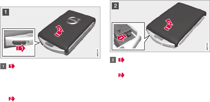
LOCKS AND ALARM
222
Changing the remote key's battery
The remote key can be opened if the battery
needs to be replaced.
The battery should be replaced if:
•The information symbol illuminates and
Unavailable Battery level too low is
shown in the display
and/or
•if the locks do not react after several
attempts to unlock or lock the vehicle
Replacing the battery
Hold the remote key with the front side
(with the Volvo symbol) toward you and move
the button on lower edge of the key near the
key ring to the right. Slide the front cover
slightly upward.
The cover will loosen and can be
removed from the key.
Move the button to the side and slide
rear cover slightly upward.
The cover will loosen and can be
removed from the key.
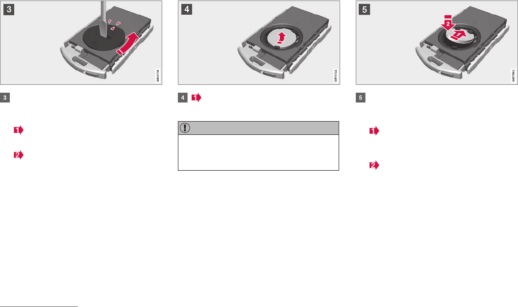
LOCKS AND ALARM
}}
223
Use e.g., a screwdriver to turn the battery
cover counterclockwise so that the markers
align toward OPEN.
Remove the cover carefully by pressing
e.g., a finger nail into the indentation.
Pry the cover up.
The battery's positive (+) side is up. Pry
out the battery as shown in the illustration.
CAUTION
When handling batteries, avoid touching their
contact surfaces as this could result in poor
battery function in the remote key.
Insert a new battery4 with the positive (+)
side up. Put the battery cover back in place
by:
Placing the battery's edge downward in
the holder. Slide the battery forward so that it
is held in place by the two plastic catches.
Pressing the battery downward so that it
is also held in place by the two upper
catches under the upper black holder.
and turn until the marker points to CLOSE.
4Use a CR2032, 3 V battery.
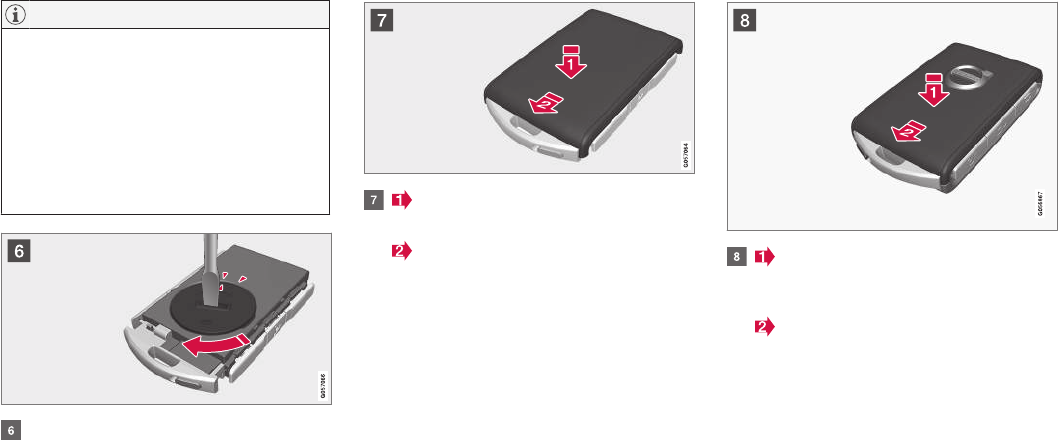
||
LOCKS AND ALARM
224
NOTE
Volvo recommends that the batteries used in
the remote control meet the UN Manual of
Test and Criteria, Part III, sub-section 38.3.
Batteries installed in the key from the factory
and batteries exchanged by an authorized
Volvo workshop fulfill the above criteria.
Old batteries should be disposed of properly
at a recycling center or at your Volvo retailer.
Put the battery cover in place and turn it
clockwise until the marker points to CLOSE.
Put the rear cover in position and press
down until it clicks into place.
Slide the cover into place as indicated by
arrow 2 in the illustration.
> Another click indicates that it is correctly
in position and closed.
Turn the key over and press the front
cover (with the Volvo logo) until it clicks into
place.
Slide the cover into position as indicated
by arrow 2 in the illustration.
> Another click indicates that it is correctly
in position and closed.
Dispose of old batteries properly, preferably at
recycling station.
Related information
•Remote key (p. 225)
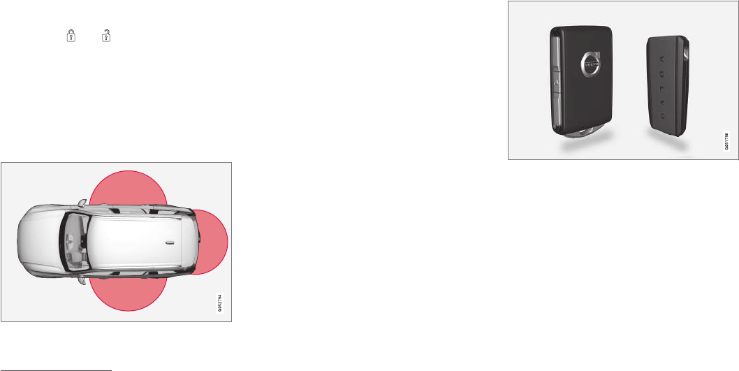
LOCKS AND ALARM
}}
225
Remote key's range
In order to function correctly, the remote key
must be within a certain distance of the vehicle.
Manual use
The remote key's functions, such as locking and
unlocking the vehicle, which are activated by
pressing the or buttons, have a range
of approx. 65 feet (20 meters) from the vehicle.
Buildings or other obstacles may interfere with
the function of the remote key. The vehicle can
also be locked or unlocked with the key blade.
If the vehicle's locks do not react, move closer
and try again.
Keyless use5
The shaded areas illustrate the range of the Passive
Entry system's antennas
For keyless entry into the vehicle, the remote key
must be within approximately 5 feet (1.5 meters)
of the sides of the vehicle or approximately 3 feet
(1 meter) of the tailgate as shown in the illustra-
tion.
The remote key may not function properly due to
ambient radio waves, buildings or topographical
obstructions, etc. The vehicle can always be
locked/unlocked with the detachable key blade.
If the remote key is removed from the
vehicle
If all of the remote keys are removed from the
vehicle while the engine is running, Vehicle key
not found Removed from vehicle will be dis-
played in the instrument panel and an audible
signal will sound when all of the doors have been
closed. The message will be erased when a
remote key has been returned to the vehicle and
the O button on the right-side steering wheel
keypad has been pressed or when all of the
doors have been closed again.
Related information
•Remote key (p. 225)
•Antenna locations for the start and lock sys-
tem (p. 220)
Remote key
The remote key is used to lock/unlock the vehi-
cle and must be in the passenger compartment
in order to start the engine.
The standard remote key (left) and the Key Tag (right)
In models with the standard Passive Start system,
the remote key only needs to be in the front sec-
tion of the passenger compartment or in the tun-
nel console cup holders in order to start the
engine.
The keyless Passive Entry system for locking/
unlocking the vehicle is available as an option.
This system has a range of approximately 5 feet
(1.5 meters) from the sides of the vehicle or
approximately 3 feet (1 meter) from the tailgate.
With this system, a remote key can be anywhere
in the vehicle.
5Models equipped with the optional Passive Entry only.
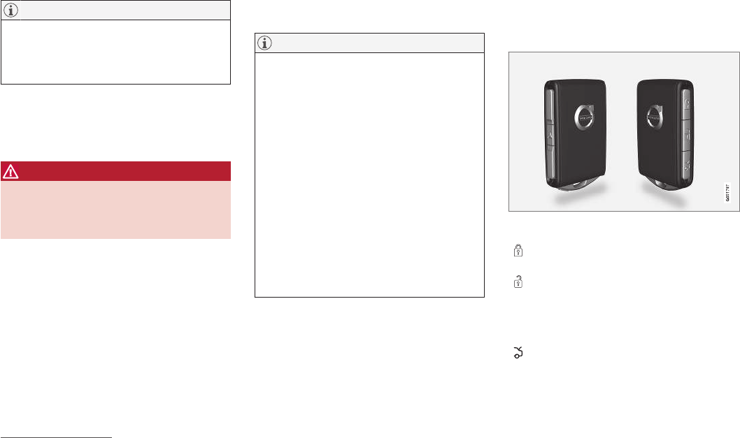
||
LOCKS AND ALARM
* Option/accessory, for more information, see Introduction.
226
NOTE
Avoid placing the remote key closer than
approx. (4-6 in.) (10-15 cm) to any metallic
objects or electronic devices such as cell
phones, tablets, laptops or chargers.
If interference persists, unlock the vehicle with
the detachable key blade and place the remote
key in the backup key reader in the tunnel con-
sole cup holder to disarm the alarm.
WARNING
Always remove the remote key from the pas-
senger compartment when leaving the vehicle
and ensure that the ignition in mode 0, espe-
cially if there are children in the vehicle.
Ordering new keys
Two remote keys are provided with the vehicle (a
Key Tag6 is also included for vehicles equipped
with the optional Passive Entry system). Addi-
tional keys (a total of 12) can be ordered and
used with the vehicle.
Loss of a remote key
If a remote key is lost, the others should be taken
with the vehicle to a Volvo retailer. As an anti-
theft measure, the code of the lost remote key
must be erased from the system. The number of
registered keys for the vehicle can be found in
the center display's Top view.
NOTE
Additional or duplicate remote control keys
can be obtained from any authorized Volvo
retailer.
You can also obtain additional or duplicate
remote control keys from certain independent
repair facilities and locksmiths that are quali-
fied to make remote control keys. Each key
must be programmed to work with your vehi-
cle.
A list of independent repair facilities and/or
locksmiths known to Volvo that can cut and
code replacement keys can be found:
•on the Volvo website,
www.volvocars.com/us
•by calling Volvo Customer Care at
1-800-458-1552.
Key Tag
In addition to the two remote keys provided, a
smaller third key, called a Key Tag, is also provi-
ded for vehicles equipped with the optional
Passive Entry system.
This key functions in the same way as a standard
remote key but does not have a detachable key
blade and its battery cannot be replaced; a new
Key Tag has to be ordered.
The remote key's buttons
The remote key has four buttons: one on the left side
and three on the right side
Lock: Press to lock the doors/tailgate and
arm the alarm.
Unlock: Press to unlock the driver's door
and disarm the alarm. Press again to unlock
the other doors and the tailgate. This setting
can be changed in the center display's Set-
tings menu.
Tailgate: Press to unlock the tailgate only
(and disarm the alarm for the tailgate). On
vehicles equipped with the power tailgate*,
press and hold to open the tailgate. Press
6The Key Tag is also referred to as a Sport key. This key is designed to be waterproof to a depth of approximately 30 ft (10 meters) for up to 60 minutes, making it suitable for use in activities in and around water.

LOCKS AND ALARM
}}
227
and hold to close an open tailgate (an audi-
ble warning signal will sound).
Panic alarm: Press to attract attention dur-
ing emergency situations. To activate, press
and hold this button for at least 3 seconds or
press it twice within 3 seconds to activate
the turn signals and horn. To deactivate,
wait approximately 5 seconds and press the
button again (the panic alarm will also deac-
tivate automatically after several minutes).
Interference
Metallic objects or electromagnetic fields may
interfere with the remote key's function. Avoid
placing the remote key within 4-6 in. (10-15 cm)
of a cell phone or a metallic object.
If interference persists, use the remote key's
detachable key blade to unlock the vehicle and
place the remote key in the backup key reader in
the tunnel console cup holder.
Loss of a remote key
If a remote keys is lost, a new one can be
ordered. The other keys should be taken with the
vehicle to a Volvo retailer or authorized independ-
ent locksmith. As an anti-theft measure, the code
of the lost remote key must be erased from the
system. The number of registered keys for the
vehicle can be found in the center display's Top
view.
Related information
•Remote key's range (p. 225)
•Detachable key blade (p. 227)
•Changing the remote key's battery (p. 222)
Detachable key blade
Your vehicle's remote key contains a detachable
key blade that can be used to unlock the driver's
door, etc.
A Volvo retailer can provide you with the key
blade's unique code.
Using the detachable key blade
The remote key's detachable key blade can be
used to:
•Unlock the driver's door if the central locking
system cannot be activated using the remote
key
•Lock all doors
•Activate/deactivate the mechanical child
safety locks in the rear doors
The Key Tag7 does not have a detachable key
blade.
7Models with the optional Passive Entry system only.
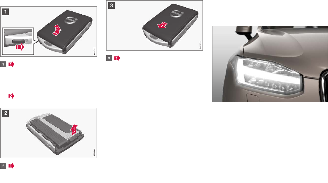
||
LOCKS AND ALARM
* Option/accessory, for more information, see Introduction.
228
Detaching the key blade
Hold the remote key with the front side
(with the Volvo symbol) toward you and move
the button on lower edge of the key near the
key ring to the right. Slide the front cover
slightly upward.
The cover will loosen and can be
removed from the key.
Remove the key blade.
After use, press the key blade back into
its position in the key, put the cover back on
the key and slide it into position.
> A click indicates that the cover is correctly
in place.
Related information
•Locking/unlocking with the detachable key
blade (p. 238)
•Child safety locks (p. 218)
Foot movement tailgate operation*
The foot movement sensor* simplifies opening or
closing the tailgate if your hands are full.8
8Models equipped with the optional power tailgate only.
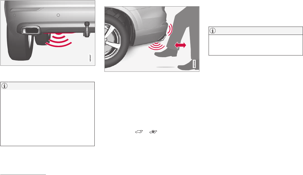
LOCKS AND ALARM
}}
* Option/accessory, for more information, see Introduction. 229
The foot movement sensor is located to the left of cen-
ter under the rear bumper9
NOTE
One of the remote keys must be in your pos-
session or within range when you are behind
the vehicle in order to activate the foot move-
ment sensor, even if the tailgate is already
unlocked. This is done to help prevent the
sensor from inadvertently opening the tail-
gate, for example, in a car wash.
Be sure that the key is not within range when
the vehicle is in an automatic carwash.
Operation
Kicking motion under the sensor's activation area
Opening/closing
–With the remote key within range, move your
foot slowly forward in a kicking motion below
the left section of the rear bumper without
touching the bumper and take a step back.
> A brief audible signal will sound when the
tailgate begins to open/close.
The tailgate can be closed (or closed and locked)
by pressing the or buttons on the lower
edge of the tailgate10.
It can also be operated manually or by pressing
the button on the lighting panel in the passenger
compartment or on the remote key.
If several attempts have been made to open/
close the tailgate using the foot sensor without a
remote key within range, the function will time
out and will not be available for a short period.
NOTE
Foot operation may not be possible or func-
tion normally if the sensor is obstructed by
snow, ice, dirt, etc.
Interrupting opening/closing
–Move your foot slowly forward in a kicking
motion while the tailgate is opening/closing
to stop its movement.
No remote keys need to be within range in order
to interrupt movement of the tailgate.
Vehicles equipped with a skid plate/
diffuser*
If the vehicle is equipped with a skid plate/
diffuser*, the sensor is located under the left cor-
ner of the rear bumper.
9If the vehicle is equipped with a skid plate/diffuser*, the sensor is located under the left corner of the bumper.
10 Vehicles equipped with the optional Passive Entry system only.
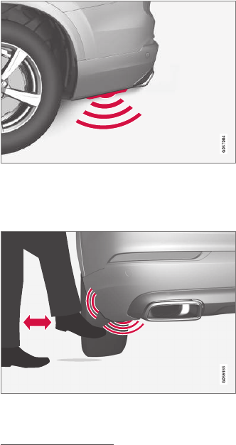
||
LOCKS AND ALARM
* Option/accessory, for more information, see Introduction.
230
Sensor location on vehicles equipped with a skid plate/
diffuser*
To open/close the tailgate, make the kicking
motion from the side of the rear bumper.
Kicking motion under the sensor's activation area
Related information
•Power tailgate* (p. 236)
•Locking/unlocking the tailgate (p. 235)
•Remote key's range (p. 225)
Locking and unlocking confirmation
The turn signals can be used to indicate that the
vehicle has been locked/unlocked with the
remote key. These settings can also be
changed.
Exterior confirmation
•Locking: the turn signals flash once and the
door mirrors will fold in (retract)11
•Unlocking: the turn signals flash twice and
the door mirrors will fold out11
When the vehicle is locked, confirmation will only
be given if all doors/tailgate and the hood are
closed.
If the vehicle is locked while only the driver's door
is closed, all doors/tailgate will lock but confirma-
tion will only be given when all doors/tailgate/
hood are closed.
11 Models with retractable door mirrors only.
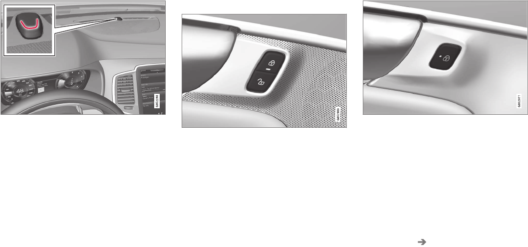
LOCKS AND ALARM
}}
231
Interior confirmation
Lock and alarm indicator light on the dashboard
A long flash indicates the vehicle is locked. While
the vehicle is locked, the indicator will flash
briefly.
LEDs in the lock buttons on the doors illuminate
when the doors are locked.
Indicators in the interior lock buttons
Lock buttons in the front doors
Front door lock buttons and indicator lights
Indicator lights on: all doors are locked.
If a door is opened, the lights in both buttons will
go out.
In all doors
Rear door lock buttons and indicator lights
Indicator light in the respective door on: that door
is locked. If either of the rear doors is opened, the
light in that door will out but the other indicator
lights will remain on.
Confirmation alternatives
Various alternatives for locking/unlocking confir-
mation can be selected in the center display.
1. Tap Settings in the center display's Top
view.
2. Tap My Car Locking.
3. Change the settings under Locking and
Unlocking Feedback.
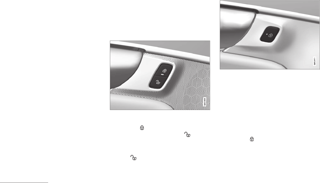
||
LOCKS AND ALARM
* Option/accessory, for more information, see Introduction.
232
Related information
•Locking/unlocking from outside the vehicle
(p. 233)
•Home safe lighting (p. 143)
•Adjusting the power door mirrors (p. 100)
Locking/unlocking from inside the
vehicle
The lock buttons on either of the front doors can
be used to lock or unlock all doors and the tail-
gate at the same time. The rear doors can be
locked using their respective lock buttons*.
The central locking system
Central locking/unlocking buttons and indicator lights
on the front doors
–Press the button on the driver's door to
lock all doors/tailgate and press to
unlock.
Unlocking
Press the button on either of the front doors
to unlock all doors and the tailgate.
Lock buttons on the rear doors*
Lock button in a rear door
The lock buttons in the rear doors lock/unlock
each door respectively.
To unlock a rear door:
–To open one of the rear doors individually,
pull its handle once and release it to unlock
the door. Pull the handle again to open the
door12.
Locking
–Press the button on either of the front
doors (both front doors must be closed). All
doors/tailgate are locked.
The rear doors can also be locked individually by
pressing the lock button on the respective door.
12 Assuming that the child safety locks are not activated.
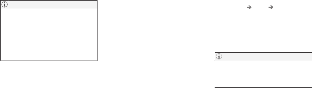
LOCKS AND ALARM
}}
* Option/accessory, for more information, see Introduction. 233
A rear door must be closed before it can be
locked.
Alternative locking when parking13
The central locking button on the front doors can
also be used to lock the vehicle when you leave
it. To do so:
1. Open the door.
2. Press the lock section of the button.
3. Close the door. This will lock the vehicle
completely and arm the alarm.
NOTE
Please be aware that locking the vehicle in
this way makes it possible to lock the remote
key in the passenger compartment. To help
avoid this, lock the vehicle from the outside by
pressing the lock button on the remote key.
If the vehicle is locked using the central lock-
ing button, be sure that the remote key is in
your possession before closing the door.
Automatic locking
All of the doors/tailgate will lock automatically
when the vehicle begins to move.
Related information
•Locking/unlocking from outside the vehicle
(p. 233)
•Child safety locks (p. 218)
Locking/unlocking from outside the
vehicle
The buttons on the remote key can be used to
lock or unlock all doors and the tailgate at the
same time. This can also be done without press-
ing the remote key buttons on models equipped
with the optional keyless Passive Entry system.
The power tailgate* can also be opened/closed
by moving your foot under a sensor beneath the
rear bumper*.
The lock/unlock settings can be changed in the
center display's Top view.
Go to: Settings My Car Remote Unlock
and select Unlock All Doors or Driver Door
Only.
In order to lock the vehicle, the driver's door must
be closed. If the tailgate or any of the other doors
are open, they will be locked and the alarm will be
armed when they are closed.
NOTE
Be sure the remote key is outside of the vehi-
cle before the other doors/tailgate are closed
to help avoid locking the remote inside the
vehicle.
If the locks repeatedly do not react when the
unlock button is pressed, it may be necessary to
13 This does not apply to models equipped with the optional Passive Entry system.
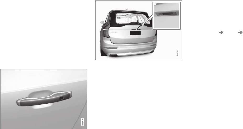
||
LOCKS AND ALARM
* Option/accessory, for more information, see Introduction.
234
replace the battery in the remote. In this case, the
driver's door can be unlocked with the detacha-
ble key blade.
Keyless Passive Entry*
If the vehicle is equipped with this system, it is
only necessary to have a remote key in your pos-
session to operate the central locking system.
Models with Passive Entry have an indentation on
the outside of the handle for locking the vehicle
and a pressure-sensitive area on the inside of the
handle for unlocking. The tailgate has a rubber-
ized button used only for locking/unlocking.
Outer indentation for locking, the pressure sensitive area
on the inside of the handle is for unlocking
Rubberized button on the tailgate used only for locking/
unlocking
Locking
All of the doors have to be closed before the
vehicle can be locked but the tailgate can be
open.
Lock the doors and tailgate by pressing the pres-
sure sensitive area on any of the door handles or
by pressing the rubberized button on the tailgate.
The lock indicator light on the dashboard will
begin to flash to show that the vehicle is locked
and the alarm has been armed.
To close any windows or the panoramic roof*
when locking the vehicle, hold the pressure sen-
sitive area for several seconds until closing
begins.
Unlocking
Pull a door handle to unlock and open the door
or press the rubberized button under the tailgate
opening control. The lock indicator light on the
dashboard will go out to show that the vehicle is
unlocked and the alarm has been disarmed.
The lock/unlock settings can be changed in the
center display's Top view:
Go to: Settings My Car Keyless Unlock
and select All Doors or Single Door.
Automatic relocking
If no door or the tailgate is opened within two
minutes after being unlocked, the vehicle will
automatically relock.
Remote door unlock
The vehicle can be unlocked using the Volvo On
Call app.
See the article "Volvo On Call mobile app" for
additional information.
Related information
•Remote key (p. 225)
•Remote key's range (p. 225)
•Detachable key blade (p. 227)
•Alarm (p. 216)
•Volvo On Call mobile app (p. 424)
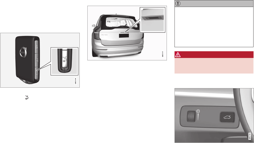
LOCKS AND ALARM
}}
* Option/accessory, for more information, see Introduction. 235
Locking/unlocking the tailgate
The tailgate can be locked/unlocked in different
ways, depending on whether the vehicle is
equipped with the optional keyless Passive Entry
system.
Unlocking with the remote key
Remote key tailgate button
1. Press the button on the remote key.
> The tailgate will be unlocked but remain
closed. The alarm indicator on the dash-
board will go out to indicate that the tail-
gate alarm is no longer armed. The other
doors will remain locked and the alarm will
remain armed for them.
2. Open the tailgate.
> If the tailgate is not opened in within two
minutes, it will relock and the alarm will
rearm.
Keyless unlocking*
Rubberized pressure plate
Opening the tailgate:
1. With the remote key in your possession,
unlock the tailgate by pressing lightly on the
rubberized pressure plate under the outer
tailgate handle. If the remote key is not
detected, the tailgate cannot be unlocked/
opened. Three audible signals will sound.
2. Lift the handle to open the tailgate fully.
CAUTION
•When pressing the rubberized pressure
plate, only light pressure is necessary to
release the tailgate's electronic locking
mechanism.
•When opening the tailgate, pull it up
using the handle. Too much pressure on
the rubberized pressure plate can dam-
age its electrical connections.
WARNING
Avoid driving with the tailgate open if at all
possible. Doing so could allow exhaust gases
to enter the passenger compartment.
Unlocking the tailgate from inside the
vehicle
Tailgate unlock button
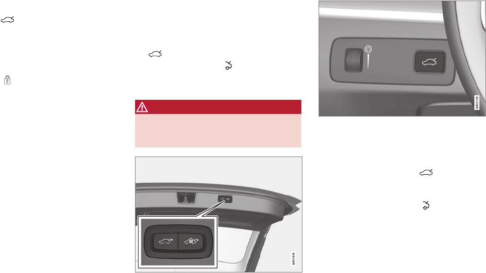
||
LOCKS AND ALARM
* Option/accessory, for more information, see Introduction.
236
To unlock the tailgate:
–Press the button on the lighting panel.
> The tailgate will unlock and can be
opened within two minutes (if the vehicle
has been locked from the inside).
Locking with the remote key
–Press the button on the remote key.
> The alarm indicator on the dashboard will
begin to flash to show that the alarm has
been armed.
Related information
•Remote key (p. 225)
•Power tailgate* (p. 236)
•Foot movement tailgate operation* (p. 228)
•Remote key's range (p. 225)
Power tailgate*
The optional power tailgate can be opened/
closed in several ways.
The power tailgate can be opened/closed using
the button on the lighting panel in the pas-
senger compartment, the on the remote key,
by moving your foot under a sensor under the
rear bumper* or manually.
WARNING
When operating the tailgate manually, do not
use force to open or close it. This could result
in injury.
Buttons in the lower edge of the tailgate
Button on the lighting panel in the passenger compart-
ment
Opening the tailgate
The power tailgate can be opened electrically by:
•Pressing and holding the button on the
lighting panel until the tailgate begins to
open.
•Pressing and holding the button on the
remote key until the tailgate begins to open.
•Pressing lightly on the rubber-covered button
under the tailgate's outside handle.
•Moving your foot under a sensor under the
rear bumper*.
Closing the tailgate
The tailgate can be closed by moving your foot
under a sensor beneath the rear bumper*, by
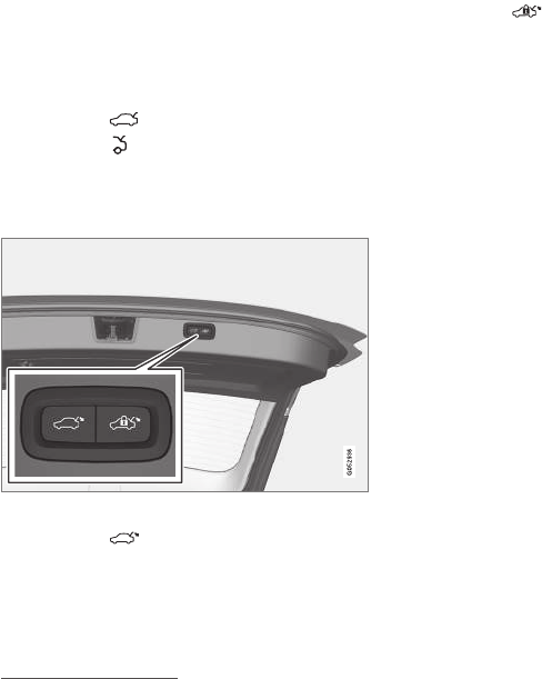
LOCKS AND ALARM
}}
* Option/accessory, for more information, see Introduction. 237
pressing the button on the lighting panel, with
the remote key or by pressing the button on the
lower edge of the tailgate*14
To close the tailgate15:
–Press the button on the lighting panel
or on the button on the remote key.
> The tailgate will close automatically and
audible signal will sound. This will not
lock the tailgate.
Buttons on the lower edge of the tailgate
–Press the button14 on the lower edge of
the tailgate.
> The tailgate will close automatically but
will not be locked.
–Press the button14 on the lower edge of
the tailgate.
> The tailgate will close automatically. The
tailgate and doors will also be locked and
the alarm will be armed.
If the remote key is not close enough to the tail-
gate, automatic locking/unlocking/opening/clos-
ing will not be possible. Three short audible sig-
nals will sound.
Interrupting opening/closing
–This can be done in five ways:
•Press the button on the lighting panel
•Press the button on the remote key
•Press either of the buttons on the lower
edge of the tailgate
•Press lightly on the rubber-covered button
under the tailgate's outside handle
•Move your foot under a sensor beneath
the rear bumper*
> The tailgate will stop moving
Programming the tailgate's maximum
opening angle
The tailgate's maximum opening angle can be
programmed, for example, if the tailgate has to be
opened in a garage with a low ceiling.
Programming the opening angle:
–Open the tailgate manually to the desired
angle and press and hold the closing button
on the tailgate's lower edge for at least 3
seconds. Release the tailgate.
> Two audible signals will sound to indicate
that the selected opening angle has been
stored.
Erasing tailgate programming
–Open the tailgate manually to its highest
position and press and hold the closing but-
ton on the tailgate's lower edge for at least 3
seconds. Release the tailgate.
> Two audible signals will sound to indicate
that the programmed opening angle has
been erased.
14 Models equipped with the optional Passive Entry system have a button to close the tailgate and a button to close and lock the tailgate.
15 See also the article "Foot movement tailgate opening/closing."
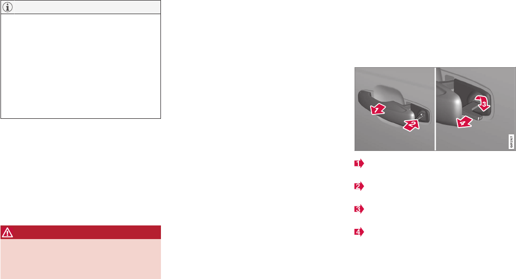
||
LOCKS AND ALARM
* Option/accessory, for more information, see Introduction.
238
NOTE
If the tailgate has been opened and closed
continuously too long, the automatic function
will be deactivated to avoid overloading the
electrical system. The automatic function can
be used again after approximately 2 minutes.
If the vehicle's battery has been discharged or
disconnected, or if the tailgate has been open
for more than 24 hours, the tailgate must be
opened and closed once manually to reset
the system.
Pinch protection
If the tailgate is obstructed when being opened/
closed, a pinch protection mechanism is acti-
vated.
•While opening: the tailgate will stop moving
and an audible signal will sound.
•While closing: the tailgate will stop and
return to the maximum programmable open-
ing position. An audible signal will sound.
WARNING
Be sure that no one is near the tailgate when
it is opened or closed automatically. The tail-
gate should never be obstructed in any way
when it is operated.
Related information
•Remote key's range (p. 225)
•Locking/unlocking from outside the vehicle
(p. 233)
•Foot movement tailgate operation* (p. 228)
Locking/unlocking with the
detachable key blade
The detachable key blade can be used to e.g.,
unlock the driver's door from the outside if, for
example, the remote key's battery is weak.
Unlocking
Pull out the driver's door handle as far as
possible to access the lock cylinder.
Remove the key blade from the remote key
and insert it into the lock cylinder.
Turn it clockwise 45 degrees so that the key
blade points straight rearward.
Turn the key blade back 45 degrees to its
original position. Remove the key blade from
the lock cylinder and release the door han-
dle.
5. Pull the door handle again to open the door.
> This will trigger the alarm.
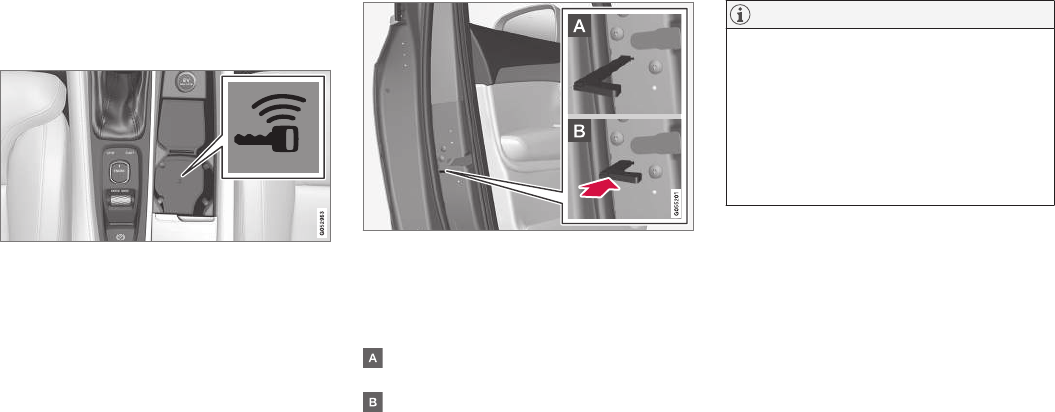
LOCKS AND ALARM
239
Lock the door in the same way, but turn the key
in step 3 counterclockwise.
Turning off the alarm
Backup key reader under the tunnel console cup hold-
ers
To turn off the alarm:
1. Place the remote key in the cup holder (on
the key symbol) in the tunnel console (see
the illustration).
2. Turn the start knob to START and release it.
> The start knob will return to its original
position and the alarm will be turned off.
Locking
If necessary, the vehicle can be locked by insert-
ing the detachable key blade into the lock cylin-
der in the driver's door.
Each of the other doors has a lock mechanism
that must be pressed in using the key blade so
that the door cannot be opened from the outside.
The doors can still be opened from the inside.
Manually locking a door (this is not the child safety lock)
–Remove the detachable key blade from the
remote key. Insert it into the opening for the
lock mechanism and press it in as far as pos-
sible.
The door can be opened from inside and the
outside.
The door cannot be opened from the outside.
To override the locking function, open the
door from the inside.
The doors can also be unlocked by pressing the
unlock button on the remote key or by pressing
the unlock button on the driver's door panel.
NOTE
If the child safety locks are activated for the
rear doors and the mechanical locking mech-
anism has also been activated with the key
blade, it will not be possible to open these
doors from the inside or the outside.
To unlock, use the central unlocking button
on either of the front doors or the unlock but-
ton on the remote key.
Related information
•Detachable key blade (p. 227)


DRIVER SUPPORT
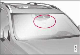
DRIVER SUPPORT
* Option/accessory, for more information, see Introduction.
242
Driver support systems
The vehicle is equipped with a number of driver
support systems that help provide the driver with
active/passive support.
Some of these systems are standard while others
are optional and they are designed to e.g., help
the driver maintain a set speed or a set distance
to a vehicle ahead, or warn the driver of a poten-
tial collision situation and in certain cases apply
the brakes if necessary. Certain optional systems
can also assist in various parking situations.
Related information
•Adjustable steering force* (p. 313)
•Electronic Stability Control (ESC) (p. 313)
•Speed limiter (SL)* (p. 288)
•Cruise Control (CC) (p. 251)
•Adaptive Cruise Control (ACC)* (p. 256)
•Pilot Assist* (p. 263)
•Distance Alert* (p. 319)
•City Safety™ (p. 277)
•Blind Spot Information (BLIS)* (p. 320)
•Cross Traffic Alert (CTA)* (p. 323)
•Driver Alert Control (DAC) (p. 317)
•Driving lane assistance (p. 328)
•Road Sign Information (RSI)* (p. 294)
•Park Assist* (p. 296)
•Park Assist Pilot (PAP)* (p. 306)
•Park Assist Camera (PAC)* (p. 301) Driver support system camera
The camera is used by a number of driver sup-
port systems to e.g., detect a driving lane's side
marker lines or traffic signs.
Camera location
The camera is used by the following driver sup-
port systems:
•Lane Departure Warning/Lane Keeping Aid*
•Driver Alert Control*
•Pilot Assist*
•City Safety
•Road sign information*
•Active high beams*
Related information
•High and low beam headlights (p. 137)
•Driving lane assistance (p. 328)
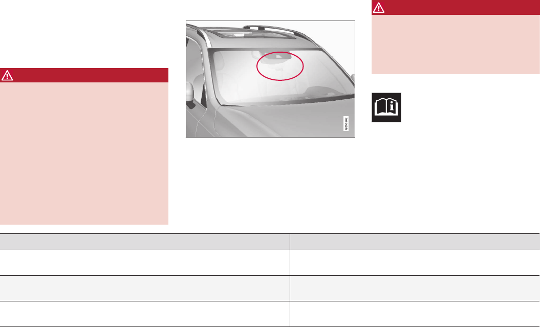
DRIVER SUPPORT
244
Camera limitations
The camera used by several of the driver support
systems has certain limitations, which also affect
the systems using it.
Reduced visibility
WARNING
•The camera has the same limitations as
the human eye. In other words, its “vision
is impaired” by adverse weather condi-
tions such as heavy snowfall, dense fog,
etc. These conditions may reduce the
function of systems that depend on the
camera or cause these systems to tem-
porarily stop functioning.
•Strong sunlight, reflections from the road
surface, ice or snow covering the road, a
dirty road surface, or unclear lane marker
lines may drastically reduce the camera’s
capacity to detect the side of a lane, a
pedestrian, a cyclist or another vehicle.
Obstructions
The marked area must not be obstructed in any way.
This area of the windshield should always be kept clean
The camera is located at the upper, center sec-
tion of the windshield along with the radar unit.
WARNING
Never place any objects, decals, etc., on the
windshield in front of the camera/radar unit.
This could reduce or block these components'
functions, and could cause one or more of the
systems that utilize the them to stop function-
ing.
If this symbol and the message
Windscreen Sensors blocked
appear in the instrument panel, this
indicates that the camera and/or radar
sensor cannot detect other vehicles ahead.
The following table shows some of the situations
that can cause the message to be displayed and
suggested actions.
Cause Action
The area of the windshield in front of the camera/radar sensor is dirty or covered
by ice or snow.
Clean the windshield or remove the ice/ snow.
Thick fog or heavy rain/snow blocks reduces the camera/radar sensor's range of
visibility.
No action. The driver should be extra alert in conditions of this type.
Water or snow on the surface of the road swirl up and block radar signals or the
camera's view.
No action. The driver should be extra alert in conditions of this type.
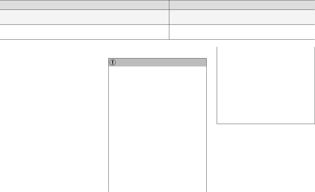
DRIVER SUPPORT
}}
245
Cause Action
There is dirt between the inside of the windshield and the camera/radar sensor. Have the area of the windshield cleaned by a trained and qualified
Volvo service technician.
Strong backlighting No action required. The came will reset automatically when lighting
conditions improve.
High temperatures
If the temperature in the passenger compartment
is very high, the camera and radar sensor may be
temporarily turned off for approx. 15 minutes
after the engine has been started to protect their
electronic components. When the temperature
has cooled sufficiently, the camera and radar
sensor will restart automatically.
Damaged windshield
CAUTION
•Service and maintenance on City Safety
may only be carried out by a trained and
qualified Volvo service technician.
•If a crack, scratch or stone chip should
occur in the section of the windshield in
front the camera/radar sensor, contact a
trained and qualified Volvo service techni-
cian to repair or replace the windshield.
Failing to do so may result in reduced
City Safety functionality.
To help prevent limited or reduced functional-
ity, please also observe the following:
•Volvo recommends that cracks, scratches
or stone chips on the windshield in front
of the camera/radar sensor should not
be repaired; in such cases, the entire
windshield should be replaced.
•Before the windshield is replaced, con-
tact a Volvo retailer to ensure that the
correct windshield is ordered and instal-
led. If the wrong type of windshield is
used, this may cause City Safety to func-
tion improperly or not at all.
•Volvo recommends the use of only Genu-
ine Volvo Replacement Windshields.
•When replacing windshield wipers, use
the same type or ones approved by Volvo.
After the windshield has been replaced, the
camera/radar sensor will have to be recalibra-
ted by a trained and qualified Volvo service
technician to help ensure proper function of
all of the vehicle's camera-/radar-based sys-
tems.
Maintenance
In order for camera and radar sensor to function
properly, the area of the windshield must be kept
free of dirt, ice, snow, etc. and should be washed
regularly with a suitable car washing detergent.
Related information
•City Safety™ (p. 277)
•Radar sensor limitations (p. 248)
•Driver support systems (p. 242)
DRIVER SUPPORT
* Option/accessory, for more information, see Introduction. 247
Driver support system radar unit
The radar unit is used by a number of driver sup-
port systems to e.g., help detect other vehicles.
The radar unit is used by the following functions:
•Distance Alert*
•Adaptive Cruise Control*
•Pilot Assist*
•City Safety
Any modifications to the radar unit may make its
use illegal.
Related information
•Radar sensor (p. 273)
•Distance Alert* (p. 319)
•Adaptive Cruise Control (ACC)* (p. 256)
•Pilot Assist* (p. 263)
•City Safety™ (p. 277)
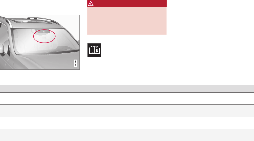
DRIVER SUPPORT
248
Radar sensor limitations
The radar sensor used by several of the driver
support systems has certain limitations, which
also affect the systems using it.
Obstructions
The marked area must not be obstructed in any way.
This area of the windshield should always be kept clean
The radar sensor is located at the upper, center
section of the windshield along with the camera.
WARNING
Never place any objects, decals, etc., on the
windshield in front of the camera/radar unit.
This could reduce or block these components'
functions, and could cause one or more of the
systems that utilize the them to stop function-
ing.
If this symbol and the message
Windscreen Sensors blocked
appear in the instrument panel, this
indicates that the camera and/or radar
sensor cannot detect other vehicles ahead.
The following table shows some of the situations
that can cause the message to be displayed and
suggested actions.
Cause Action
The area of the windshield in front of the camera/radar sensor is dirty or covered by ice or
snow.
Clean the windshield or remove the ice/ snow.
Thick fog or heavy rain/snow blocks reduces the camera/radar sensor's range of visibility. No action. The driver should be extra alert in conditions of this
type.
Water or snow on the surface of the road swirl up and block radar signals or the camera's
view.
No action. The driver should be extra alert in conditions of this
type.
There is dirt between the inside of the windshield and the camera/radar sensor. Have the area of the windshield cleaned by a trained and quali-
fied Volvo service technician.
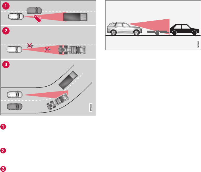
DRIVER SUPPORT
}}
249
The radar sensor's capacity to detect vehicles
ahead is impeded:
•if the speed of the vehicle ahead differs
greatly from your vehicle's speed.
Limited field of vision
The radar sensor has a limited field of vision. In
some situations it may detect a vehicle later than
expected or not detect other vehicles at all.
Radar sensor's field of vision
In certain situations, the radar sensor cannot
detect vehicles at close quarters, for example
a vehicle that suddenly enters the lane
between your vehicle and the target vehicle.
Small vehicles, such as motorcycles, or vehi-
cles not driving in the center of the lane may
remain undetected.
In curves, the radar sensor may detect the
wrong vehicle or lose sight of the target vehi-
cle.
Low trailer in the radar shadow
Low trailers may also be difficult to detect or may
not be detected at all. The driver should be extra
alert in situations of this type.
High temperatures
If the temperature in the passenger compartment
is very high, the camera and radar sensor may be
temporarily turned off for approx. 15 minutes
after the engine has been started to protect their
electronic components. When the temperature
has cooled sufficiently, the camera and radar
sensor will restart automatically.

||
DRIVER SUPPORT
* Option/accessory, for more information, see Introduction.
250
Damaged windshield
CAUTION
•Service and maintenance on City Safety
may only be carried out by a trained and
qualified Volvo service technician.
•If a crack, scratch or stone chip should
occur in the section of the windshield in
front the camera/radar sensor, contact a
trained and qualified Volvo service techni-
cian to repair or replace the windshield.
Failing to do so may result in reduced
City Safety functionality.
To help prevent limited or reduced functional-
ity, please also observe the following:
•Volvo recommends that cracks, scratches
or stone chips on the windshield in front
of the camera/radar sensor should not
be repaired; in such cases, the entire
windshield should be replaced.
•Before the windshield is replaced, con-
tact a Volvo retailer to ensure that the
correct windshield is ordered and instal-
led. If the wrong type of windshield is
used, this may cause City Safety to func-
tion improperly or not at all.
•Volvo recommends the use of only Genu-
ine Volvo Replacement Windshields.
•When replacing windshield wipers, use
the same type or ones approved by Volvo.
After the windshield has been replaced, the
camera/radar sensor will have to be recalibra-
ted by a trained and qualified Volvo service
technician to help ensure proper function of
all of the vehicle's camera-/radar-based sys-
tems.
Maintenance
In order for camera and radar sensor to function
properly, the area of the windshield must be kept
free of dirt, ice, snow, etc. and should be washed
regularly with a suitable car washing detergent.
Related information
•City Safety™ (p. 277)
•Driver support systems (p. 242)
•Road Sign Assistance (RSI)* limitations
(p. 296)
•Park Assist Pilot (PAP)* limitations (p. 310)
•City Safety limitations (p. 283)
•Driving lane assistance (p. 328)
•Adaptive Cruise Control (ACC)* (p. 256)
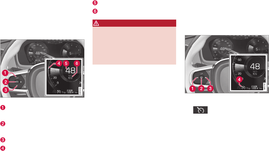
DRIVER SUPPORT
}}
* Option/accessory, for more information, see Introduction. 251
Cruise Control (CC)
Cruise Control (CC) is designed to assist the
driver by maintaining a set speed. It is primarily
intended for use on long straight roads in steady
traffic, such as on highways and other main
roads in smoothly flowing traffic.
Overview
Function buttons and symbols
Increases the set speed or CC switches from
standby mode to active mode and the set
speed will be resumed
Press to put CC in active mode and set the
current speed or from active mode, press to
put CC in standby mode
Reduces the set speed
Set speed indicator
The vehicle's current speed
The set speed
WARNING
•The vehicle must always be driven
according to current traffic/road condi-
tions. The driver must take action if CC
does not maintain a suitable speed
and/or distance to other vehicles.
•The driver is always responsible for oper-
ating the vehicle in a safe manner.
Related information
•Starting and activating Cruise Control
(p. 251)
•Changing Cruise Control speed (p. 252)
•Deactivating/resuming Cruise Control (CC)
(p. 253)
•Turning Cruise Control off (p. 254)
•Adaptive Cruise Control (ACC)* (p. 256)
•Switching between Cruise Control (CC) and
Adaptive Cruise Control (ACC)* (p. 255)
Starting and activating Cruise
Control
Cruise Control (CC) must be selected and acti-
vated before it can regulate the vehicle's speed.
Selecting CC (putting it in standby
mode)
Function buttons and symbols
–Press ◀ (1) or ▶ (3) to scroll to the CC
() function.
> The symbol (4) will be displayed in the
instrument panel. This indicates that CC
has been selected and can then be acti-
vated to maintain a set speed.
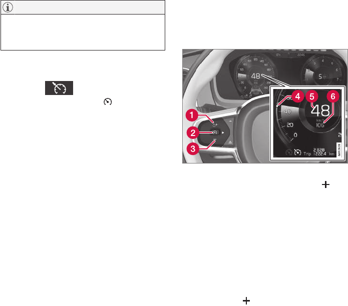
||
DRIVER SUPPORT
* Option/accessory, for more information, see Introduction.
252
NOTE
Before CC can be activated, the vehicle's
speed must be at least 20 mph (30 km/h).
This is also the lowest speed that can be set.
Activating CC (putting it in active mode
and setting a speed)
–With the symbol displayed (CC is in
standby mode), press the button (2) on
the left-side steering wheel keypad.
> This puts CC in active mode and will
maintain the vehicle's current speed.
Related information
•Cruise Control (CC) (p. 251)
•Switching between Cruise Control (CC) and
Adaptive Cruise Control (ACC)* (p. 255)
•Deactivating/resuming Cruise Control (CC)
(p. 253)
•Turning Cruise Control off (p. 254)
Changing Cruise Control speed
Cruise Control (CC) helps the driver maintain a
set speed.
Changing a set speed
Function buttons and symbols
–Change a set speed by pressing the (1)
or — (2) buttons briefly or by pressing and
holding them:
•Press briefly: changes speed in
+/– 1 mph (+/– 1 km/h) increments.
Each press changes the vehicle's speed
by +/– 1 mph (+/– 1 km/h).
•Press and hold: Release the button
when the set speed indicator (4) has
moved to the desired speed.
If speed is increased by pressing the accelerator
pedal before the button is pressed, the vehi-
cle's speed when the button is pressed will
become the set speed assuming that the accel-
erator pedal is still depressed when the button is
pressed.
A temporary increase in speed, such as when
passing another vehicle, does not affect the CC
set speed. The vehicle will return to the set speed
when the accelerator pedal is released.
Engine braking instead of applying the
brakes
CC regulates speed by applying the brakes
lightly. To avoid a loss of speed when driving
down hills, use the engine braking function
instead of letting the CC apply the brakes. In this
situation, the driver can temporarily deactivate the
CC braking function.
To do so:
–Press the accelerator pedal approx. halfway
down and release it.
> CC will automatically deactivate the auto-
matic brake function and will then only
use the engine braking function.
Related information
•Cruise Control (CC) (p. 251)
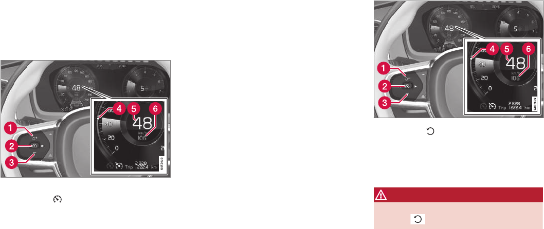
DRIVER SUPPORT
}}
253
Deactivating/resuming Cruise
Control (CC)
Cruise Control (CC) can be temporarily deacti-
vated and put in standby mode.
Deactivating and putting CC in standby
mode
To temporarily deactivate and put Cruise Control
in standby mode:
Function buttons and symbols
–Press the button (2).
> The set speed marker (4) and symbols will
change colors from WHITE to GRAY.
This indicates that CC is temporarily in
standby mode and will not maintain a set
speed.
Standby mode due to action by the driver
CC is temporarily deactivated and put in standby
mode if:
•the brakes are applied
•The gear selector is moved to N
•the vehicle is driven faster than the set
speed for more than 1 minute.
In these cases, the driver will have to regulate the
vehicle's speed.
A temporary increase in speed, such as when
passing another vehicle, does not affect the CC
set speed. The vehicle will return to the set speed
when the accelerator pedal is released.
Automatic standby mode
CC switches automatically to standby mode if:
•the wheels lose traction
•engine speed (rpm) is too high/low
•brake temperature is too high
•the vehicle's speed goes below approx.
20 mph (30 km/h)
In these cases, the driver will have to regulate the
vehicle's speed.
Reactivating CC from standby mode
To reactivate CC after it has temporarily been put
in standby mode:
–Press the button (1).
> The set speed marker (4) will change
color from GRAY to WHITE. The vehicle
will then return to the most recently set
speed.
WARNING
There may be a significant increase in speed
after the button has been pressed.
or
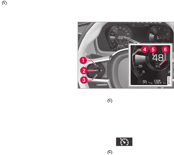
||
DRIVER SUPPORT
254
–Press the button (2).
> The set speed marker (4) and symbols will
change colors from GRAY to WHITE. CC
will then set and maintain the vehicle's
current speed.
Related information
•Cruise Control (CC) (p. 251)
•Starting and activating Cruise Control
(p. 251)
Turning Cruise Control off
Cruise Control (CC) can be deactivated (turned
off).
Function buttons and symbols
1. Press the button (2) on the left-side
steering wheel keypad.
> This puts CC in standby mode.
2. Press the ◀ or ▶ button to switch to another
function.
> The Cruise Control symbol in the instru-
ment panel ( ) will go out.
3. Press the button (2) again.
> Another function will be activated and the
set speed in the CC system's memory will
be erased.
Related information
•Cruise Control (CC) (p. 251)
•Starting and activating Cruise Control
(p. 251)
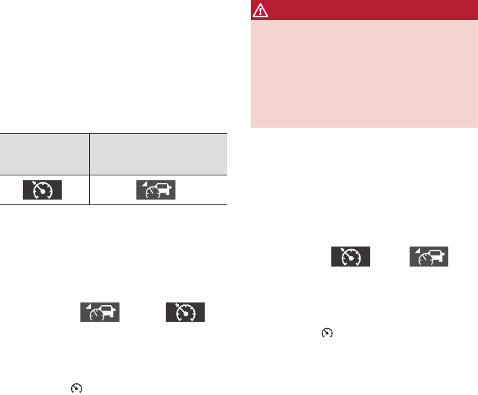
DRIVER SUPPORT
* Option/accessory, for more information, see Introduction. 255
Switching between Cruise Control
(CC) and Adaptive Cruise Control
(ACC)*
In models equipped with the optional ACC, the
driver can toggle between CC and ACC.
Switching from ACC till CC
A symbol in the instrument panel will indicate
which system is currently being used:
CC
Cruise Control
ACC
Adaptive Cruise Control
A A
AIf the symbol is WHITE, the function is active. If the symbol is
GRAY, the function is in standby mode.
To switch from ACC to CC
1. From the center display's Function view, tap
the Activate cruise control button.
> The symbol in the instrument panel will
change from (ACC) to
(CC). This means that ACC has been com-
pletely deactivated (turned off) and CC is in
standby mode (ready for use but not cur-
rently maintaining a set speed).
2. Press the button on the left-side steer-
ing wheel keypad: CC goes into active mode
and sets the vehicle's current speed.
WARNING
Switching from ACC to CC means that:
•Your vehicle will no longer automatically
maintain a set distance to a vehicle
ahead.
•Only the set speed will be maintained and
the driver will have to apply the brakes
when needed.
If CC was activated when the engine was turned
off, ACC will be selected and go into standby
mode when the engine is restarted.
Switching from CC back to ACC
1. In the center display's Function view, tap the
Activate cruise control button.
> The symbol in the instrument panel will
change from (CC) to
(ACC). This means that CC has been com-
pletely deactivated (turned off) and ACC is in
standby mode (ready for use but not cur-
rently maintaining a set speed/time interval).
2. Press the button on the left-side steer-
ing wheel keypad: ACC goes into active
mode and sets the vehicle's current speed
and the selected distance to the vehicle
ahead.
Related information
•Adaptive Cruise Control (ACC)* (p. 256)
•Cruise Control (CC) (p. 251)
•Center display overview (p. 28)

DRIVER SUPPORT
* Option/accessory, for more information, see Introduction.
256
Adaptive Cruise Control (ACC)*
ACC is an optional system designed to assist
the driver by maintaining a set speed or a set
time interval to the vehicle ahead.
The driver sets that desired speed and time inter-
val to the vehicle ahead. When the camera and
radar sensor detects a slower moving vehicle
ahead, your vehicle's speed is automatically
adapted. When there are no longer slower mov-
ing vehicles ahead, your vehicle will accelerate to
resume the set speed.
ACC is designed to follow a vehicle ahead in the
same lane and maintain a time interval to that
vehicle set by the driver. If the radar sensor does
not detect a vehicle ahead, ACC will instead
maintain the speed set by the driver.
ACC is designed to smoothly regulate speed.
However, the driver must apply the brakes in sit-
uations that require immediate braking. This
applies when there are great differences in
speed between vehicles, or if the vehicle ahead
brakes suddenly. Due to limitations in the radar
sensor, braking may occur unexpectedly or not at
all.
Adaptive Cruise Control can follow another vehi-
cle from a standstill up to 125 mph (200 km/h).
Always observe posted speed limits.
WARNING
•It is advisable to read through all of the
related articles pertaining to ACC (see
the list at the end of this article).
•Adaptive Cruise Control cannot cover all
driving situations and traffic, weather and
road conditions.
•This system is designed to be a supple-
mentary driving aid. It is not, however,
intended to replace the driver's attention
and judgement. The driver is responsible
for maintaining a safe distance and speed
and must intervene if Adaptive Cruise
Control does not maintain a suitable
speed or suitable distance to the vehicle
ahead.
•Maintenance of ACC components may
only be performed by a trained and quali-
fied Volvo technician.
Overview
The distance to the vehicle ahead (in the same
lane) is monitored by a radar sensor. Your vehi-
cle's speed is regulated by accelerating and
braking. The brakes may emit a sound when they
are being modulated by the adaptive cruise con-
trol system. This is normal.
WARNING
•Adaptive Cruise Control is not a collision
avoidance system. The driver is always
responsible for applying the brakes if the
system does not detect another vehicle.
•Adaptive Cruise Control does not react to
people or animals, or small vehicles such
as bicycles and motorcycles. It also does
not react to slow moving, parked or
approaching vehicles, or stationary
objects.
•Do not use Adaptive Cruise Control in
demanding driving conditions such as city
driving or other heavy traffic situations, in
slippery conditions, when there is a great
deal of water or slush on the road, during
heavy rain or snow, in poor visibility, on
winding roads or on highway on- or off-
ramps.

DRIVER SUPPORT
}}
257
Controls
Function buttons and symbols
Increases the set speed or puts ACC back
into active mode (previous settings will be
resumed)
Puts ACC in active mode and stores the cur-
rent speed or puts ACC standby mode
Reduces the set speed
Target vehicle indicator: ACC has detected
and is following a target vehicle using the set
time interval
Instrument panel
Speed indicators
Set speed
Speed of the vehicle ahead
The current speed of your vehicle
Collision warning
Warning light
Adaptive Cruise Control can exert brake force
that is equivalent to approximately 40% of the
vehicle's total braking capacity.
In situations requiring more brake force than
ACC can provide and if the driver does not apply
the brakes, an audible signal from the City Safety
system will sound and warning light will illuminate
in the windshield to alert the driver to react.
NOTE
Strong sunlight, reflections, extreme light con-
trasts, the use of sunglasses, or if the driver is
not looking straight ahead may make the vis-
ual warning signal in the windshield difficult to
see.
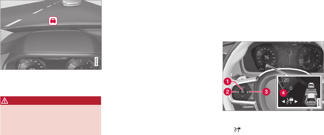
||
DRIVER SUPPORT
* Option/accessory, for more information, see Introduction.
258
Head-up-display*
A flashing light alerts the driver
A flashing icon will appear in the head-up dis-
play* to alert the driver of a collision risk.
WARNING
Adaptive Cruise Control only warns of vehicles
detected by the radar sensor. In some cases
there may be no warning or the warning may
be delayed. The driver should always apply the
brakes when necessary.
Related information
•Adaptive Cruise Control (ACC) - fault tracing
(p. 275)
•Starting and activating Adaptive Cruise
Control (ACC) (p. 258)
•Adaptive cruise control passing assistance
(p. 274)
•Setting an Adaptive Cruise Control time
interval (p. 262)
•Deactivating/resuming Adaptive Cruise
Control (ACC) (p. 259)
•Adaptive Cruise Control (ACC) symbols and
messages (p. 276)
•Switching between Cruise Control (CC) and
Adaptive Cruise Control (ACC)* (p. 255)
Starting and activating Adaptive
Cruise Control (ACC)
ACC must first be put in active mode before it
can be started in order to regulate speed or a
set time interval to the vehicle ahead.
Starting ACC (putting it in standby
mode)
Function buttons and symbols
–Press ◀ (2) or ▶ (3) to scroll to the ACC
() function. The symbol (4) will be dis-
played in the instrument panel.
> The symbol indicates that ACC has been
started and is in standby mode. In
standby mode, the vehicle will not main-
tain a set speed or a time interval to the
vehicle ahead.
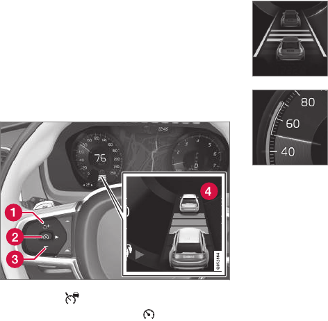
DRIVER SUPPORT
}}
* Option/accessory, for more information, see Introduction. 259
Activating ACC (putting it in active
mode and setting a speed)
Before ACC can be put in active mode:
•The driver's seat belt must be buckled and
the driver's door must be closed.
•There must be a vehicle ahead (a target vehi-
cle) or your vehicle's current speed must be
at least 10 mph (15 km/h).
–With the symbol displayed (ACC is in
standby mode), press the button (1) on
the left-side steering wheel keypad.
> This puts ACC in active mode and sets
the vehicle's current speed, which is indi-
cated by digits in the center of the speed-
ometer.
The time interval to the vehi-
cle ahead will only be shown
when two vehicles are dis-
played.
A speed interval will also be
indicated:
•The higher speed is the one set in ACC
•The lower one is the speed of the vehicle
ahead (the target vehicle).
Related information
•Adaptive Cruise Control (ACC)* (p. 256)
•Setting an Adaptive Cruise Control time
interval (p. 262)
•Deactivating/resuming Adaptive Cruise
Control (ACC) (p. 259)
Deactivating/resuming Adaptive
Cruise Control (ACC)
ACC can be put temporarily in standby mode
and then reactivated.
Deactivating and putting ACC in
standby mode
If ACC is in standby mode and your vehicle
comes too close to the vehicle ahead, the driver
will be warned by the Distance Alert system
instead.
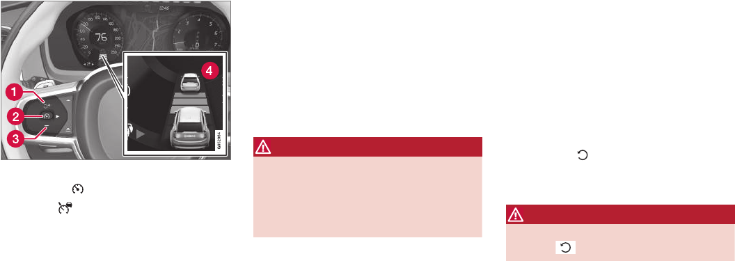
||
DRIVER SUPPORT
* Option/accessory, for more information, see Introduction.
260
To temporarily deactivate and put Adaptive Cruise
Control in standby mode:
Function buttons and symbols
–Press the button (2).
>The symbol in the instrument panel
will change colors from WHITE to GRAY
and the set speed in the center of the
speedometer will change from BEIGE to
GRAY.
Standby mode due to action by the driver
ACC is temporarily deactivated and put in
standby mode if:
•the brakes are applied
•The gear selector is moved to N
•the vehicle is driven faster than the set
speed for more than 1 minute.
In these cases, the driver will have to regulate the
vehicle's speed.
A temporary increase in speed, such as when
passing another vehicle, does not affect the ACC
set speed. The vehicle will return to the set speed
when the accelerator pedal is released.
Automatic standby mode
ACC interacts with other systems, such as
Electronic Stability Control. If any of these other
systems are not functioning properly, ACC will
turn off automatically.
WARNING
If this happens, the driver will be alerted by an
audible signal and a message in the instru-
ment panel. The driver will have to adapt the
vehicle's speed, apply the brakes when nec-
essary and keep a safe distance to the vehicle
ahead.
ACC switches automatically to standby mode if:
•the vehicle's speed goes below approx.
3 mph (5 km/h) and ACC cannot determine
if the vehicle ahead is stationary or is an
object such as a speed bump, etc
•the vehicle's speed goes below approx.
3 mph (5 km/h) and the vehicle ahead
changes lanes or turns so that ACC no
longer has a target vehicle to follow
•the driver opens the door
•the driver unbuckles the seat belt
•engine speed (rpm) is too high/low
•the wheels lose traction
•the parking brake is applied
•the stability system's ESC Sport Mode is
activated
•the Off Road drive mode is selected
•The radar sensor is covered by e.g., wet snow
or if heavy rain interferes with radar waves
Reactivating ACC from standby mode
To reactivate ACC after it has temporarily been
put in standby mode:
–Press the button (1).
>The vehicle will then return to the most
recently set speed.
WARNING
There may be a significant increase in speed
after the button has been pressed.
Related information
•Adaptive Cruise Control (ACC)* (p. 256)
•Starting and activating Adaptive Cruise
Control (ACC) (p. 258)
•Setting an Adaptive Cruise Control time
interval (p. 262)
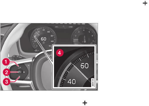
DRIVER SUPPORT
}}
261
•Adaptive cruise control passing assistance
(p. 274)
•Adaptive Cruise Control (ACC) symbols and
messages (p. 276)
Changing Adaptive Cruise Control
(ACC) speed
ACC makes it possible to set various speeds.
Changing a set speed
Function buttons and symbols
–Change a set speed by pressing the (1)
or — (3) buttons briefly or by pressing and
holding them:
•Press briefly: changes speed in
+/– 5 mph (+/– 5 km/h) increments.
Each press changes the vehicle's speed
by +/– 5 mph (+/– 5 km/h).
•Press and hold: changes the speed
+/– 1 mph (+/– 1 km/h) at a time.
Release the button when the set speed
indicator (4) has moved to the desired
speed.
If speed is increased by pressing the accelerator
pedal before the button is pressed, the vehi-
cle's speed when the button is pressed will
become the set speed assuming that the accel-
erator pedal is still depressed when the button is
pressed.
A temporary increase in speed, such as when
passing another vehicle, does not affect the ACC
set speed. The vehicle will return to the set speed
when the accelerator pedal is released.
The lowest speed that can be set for ACC is
20 mph (30 km/h). However, ACC can monitor
and react to the speed of the vehicle ahead down
to a standstill.
ACC not installed at the factory
This function can be installed in the vehicle after
delivery if it is equipped with the normal cruise
control. If ACC was installed after the vehicle was
purchased, it will differ from the factory-installed
version as follows:
•If the speed of the vehicle ahead goes below
18 mph (30 km/h), ACC disengages (goes
into standby mode) and will no longer modu-
late the brakes. The driver will then have to
maintain a safe distance to the vehicle ahead
•The lowest speed at which ACC can be
started is 20 mph (30 km/h)
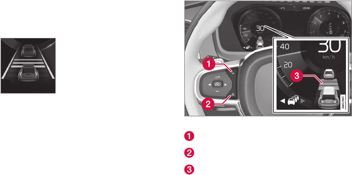
||
DRIVER SUPPORT
* Option/accessory, for more information, see Introduction.
262
Related information
•Adaptive Cruise Control (ACC)* (p. 256)
•Starting and activating Pilot Assist (p. 266)
•Setting an Adaptive Cruise Control time
interval (p. 262)
Setting an Adaptive Cruise Control
time interval
ACC makes it possible to set various time inter-
vals to the vehicle ahead.
Different time intervals to the
vehicle ahead can be selected
and are shown in the instru-
ment panel as 1–5 horizontal
bars. The greater the number of
bars, the longer the time inter-
val. One bar between the vehi-
cles represents a time interval of approximately
1 second; 5 bars is approximately 3 seconds.
The same symbol appears if Distance Alert is
activated.
•If the symbol shows two vehicle's, ACC is
actively following the vehicle ahead.
•If only one vehicle is displayed, ACC is not
actively following another vehicle.
Changing a time interval
Controls for setting a time interval
Reduce the time interval
Increase the time interval
Distance/time indicator
–Press buttons (1) or (2) to reduce or
increase the time interval.
> The distance/time indicator (3) shows the
current time interval.
In order to follow the vehicle ahead as smoothly
as possible, ACC allows the time interval to vary
considerably in certain situations. At low speeds,
when the distance to the vehicle ahead is short,
ACC increases the time interval slightly.
•If ACC does not seem to react when it is put
in active mode, this may be because the set
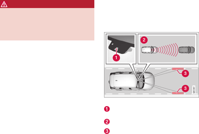
DRIVER SUPPORT
}}
* Option/accessory, for more information, see Introduction. 263
time interval to the vehicle ahead does not
allow an increase in speed.
•The higher the speed, the greater the dis-
tance to the vehicle ahead for a given time
interval.
•Only use time intervals permitted by local
traffic regulations.
WARNING
•Only use a time interval that is suitable in
current traffic conditions.
•A short time interval gives the driver lim-
ited reaction time if an unexpected situa-
tion occurs in traffic.
Related information
•Adaptive Cruise Control (ACC)* (p. 256)
•Starting and activating Adaptive Cruise
Control (ACC) (p. 258)
•Deactivating/resuming Adaptive Cruise
Control (ACC) (p. 259)
•Adaptive cruise control passing assistance
(p. 274)
•Adaptive Cruise Control (ACC) symbols and
messages (p. 276)
Pilot Assist*
The Pilot Assist feature helps keep the vehicle in
its current traffic lane, at a set speed and a set
time interval to the vehicle ahead.
Function
The vehicle's camera monitors the traffic lane's
side marker lines and a distance monitor helps
maintain the set time interval to the vehicle
ahead.
Pilot Assist helps provide more relaxed driving in
heavy, slow-moving traffic at speeds up to
30 mph (50 km/h) on highways and major roads.
Function overview
Windshield module containing the camera/
radar sensor
Monitoring distance
Monitoring side marker lines
The driver sets the desired time interval to the
vehicle ahead. Pilot Assist monitors that vehicle
and the traffic lane's side market lines using the
camera and radar sensor mounted in the upper,
center section of the windshield. It helps maintain
the set time interval by automatically adjusting
speed and by providing steering assistance to
help keep your vehicle in the lane.
Pilot Assist's steering assistance is based on
monitoring the direction of the vehicle ahead and
the traffic lane's side marker lines. The driver can
always override Pilot Assist and steer the vehicle
to e.g., change lanes, etc.
If the camera and radar sensor cannot detect the
lane's side marker lines or a vehicle ahead, Pilot
Assist goes into standby mode.
When Pilot Assist is in standby mode and your
vehicle comes too close to the vehicle ahead, the
driver will be alerted by the Distance Alert func-
tion.
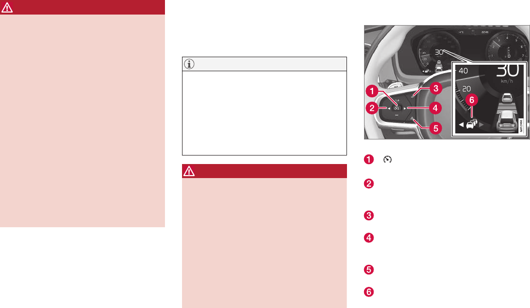
||
DRIVER SUPPORT
264
WARNING
•Pilot Assist is designed to be a supple-
mentary driving aid and cannot cover all
driving situations, traffic, weather and/or
road conditions.
•The driver should be familiar with all of
the information in this article regarding
Pilot Assist, including its limitations.
•Pilot Assist is not intended to replace the
driver's attention and judgement.
•Pilot Assist must only be used where
there are clearly visible traffic lane side
marker lines on both sides of the current
traffic lane. In other circumstances there
is an increased risk of collision with sur-
rounding obstacles that are not detected
by the system.
•The driver is always responsible for steer-
ing the vehicle and maintaining a suitable
speed and distance to the vehicle ahead
and must intervene if necessary, even if
Pilot Assist is being used.
Pilot Assist is designed to regulate speed
smoothly but in situations calling for fast braking,
the driver must apply the brakes. This applies to
situations where there are considerable differen-
ces in speed or if the vehicle ahead brakes sud-
denly. Due to the limitations of the camera and
radar sensor, the system may apply the brakes in
your vehicle suddenly or not at all.
The default speed for Pilot Assist is preset to
approx. 30 mph (50 km/h) and cannot be
changed. If the vehicle ahead increases speed to
over 30 mph (50 km/h) and pulls away from your
vehicle, Pilot Assist will go into standby mode.
NOTE
•Pilot Assist maintenance should only be
carried out by a trained and qualified
Volvo service technician.
•Pilot Assist regulates your vehicle's
speed using the accelerator pedal and
the brakes. Please be aware that there
may be a faint sound from the brakes
when the system is using them.
WARNING
•Pilot Assist does not react to people or
animals, or small vehicles such as bicy-
cles and motorcycles. It also does not
react to low trailers, slow moving, parked
or approaching vehicles, or stationary
objects.
•Do not use Pilot Assist in demanding
driving conditions such as city driving or
other heavy traffic situations, in slippery
conditions, when there is a great deal of
water or slush on the road, during heavy
rain or snow, in poor visibility, on winding
roads or on highway on- or off-ramps.
Pilot Assist overview
Controls
Function buttons and symbols
[ ]: Press to activate Pilot Assist or put it
in standby mode
Arrow key [ < ]: change from Pilot Assist to
Adaptive Cruise Control (symbol (6) will also
change)
Reduce the distance (time interval) to the
vehicle ahead
Arrow key [ > ]: change from Adaptive Cruise
Control to Pilot Assist (symbol (6) will also
change)
Increase the distance (time interval) to the
vehicle ahead
Function symbols
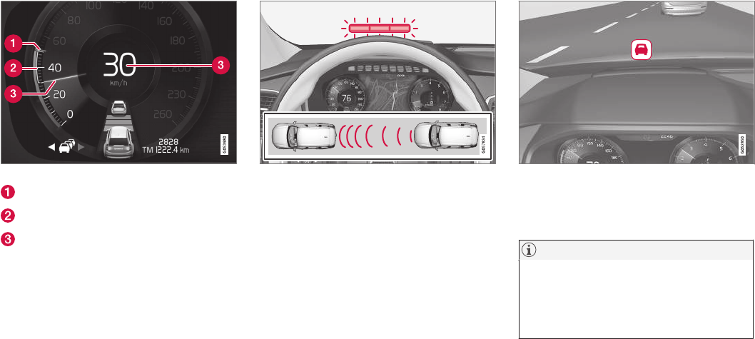
DRIVER SUPPORT
}}
* Option/accessory, for more information, see Introduction. 265
Instrument panel
Speed indication
Set speed
Speed of the vehicle ahead
Your vehicle's current speed.
Collision warning
Warning light
Pilot Assist can exert brake force that is equiva-
lent to approximately 40% of the vehicle's total
braking capacity.
In situations requiring more brake force than Pilot
Assist can provide and if the driver does not
apply the brakes, an audible signal from the City
Safety system will sound and warning light will
illuminate in the windshield to alert the driver to
react.
Head-up-display*
A flashing symbol alerts the driver
If the vehicle is equipped with a head-up display*,
a flashing symbol in the windshield will alert the
driver.
NOTE
Strong sunlight, reflections, extreme light con-
trasts, the use of sunglasses, or if the driver is
not looking straight ahead may make the vis-
ual warning signal in the windshield difficult to
see.
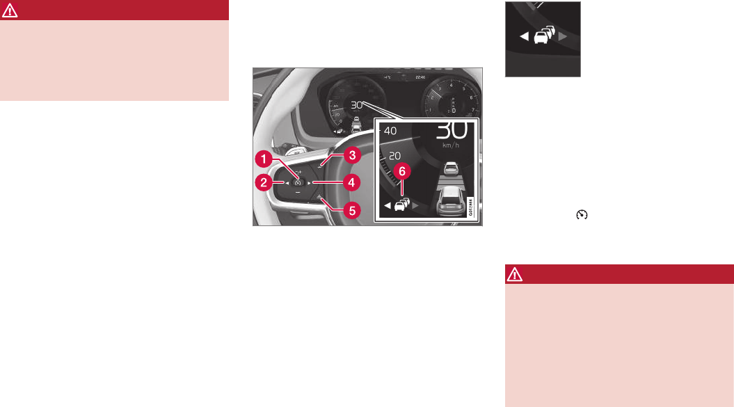
||
DRIVER SUPPORT
* Option/accessory, for more information, see Introduction.
266
WARNING
Pilot Assist only provides warnings for vehi-
cles that its radar sensor and camera have
detected. For this reason, a warning may be
given later than expected or not at all. The
driver should never wait for a warning before
applying the brakes.
Related information
•Pilot Assist limitations (p. 270)
•Pilot Assist auto-hold brake function
(p. 269)
•Distance Alert* (p. 319)
•Other Adaptive Cruise Control (ACC) func-
tions (p. 272)
•Setting an Adaptive Cruise Control time
interval (p. 262)
Starting and activating Pilot Assist
The Pilot Assist feature helps keep the vehicle in
its current traffic lane, at a set speed and a set
time interval to the vehicle ahead.
Function buttons and symbols
Prerequisites
The prerequisites for activating Pilot Assist are:
•The vehicle ahead must be within a reasona-
ble (detectable) distance
•The camera must be able to clearly detect
the traffic lane's side marker lines
•The vehicle's speed must be under approx.
30 mph (50 km/h).
A WHITE symbol indicates that
Pilot Assist has been selected.
In other cases, the WHITE
arrow pointing to the right indi-
cates that the system is availa-
ble.
A YELLOW symbol with a flashing WHITE arrow
indicates that the system is about to shift into
standby mode.
With ACC in standby mode:
1. Tap ▶ (4).
> The symbol will be displayed and Pilot
Assist will go into standby mode.
2. Press the button (1) on the left-side
steering wheel keypad.
> Pilot Assist will go into active mode.
WARNING
•Pilot Assist is not a collision avoidance
system. The driver is always responsible
for applying the brakes if the system does
not detect another vehicle.
•Do not use Pilot Assist in demanding
driving conditions such as city driving or
other heavy traffic situations, in slippery
conditions, when there is a great deal of
water or slush on the road, during heavy
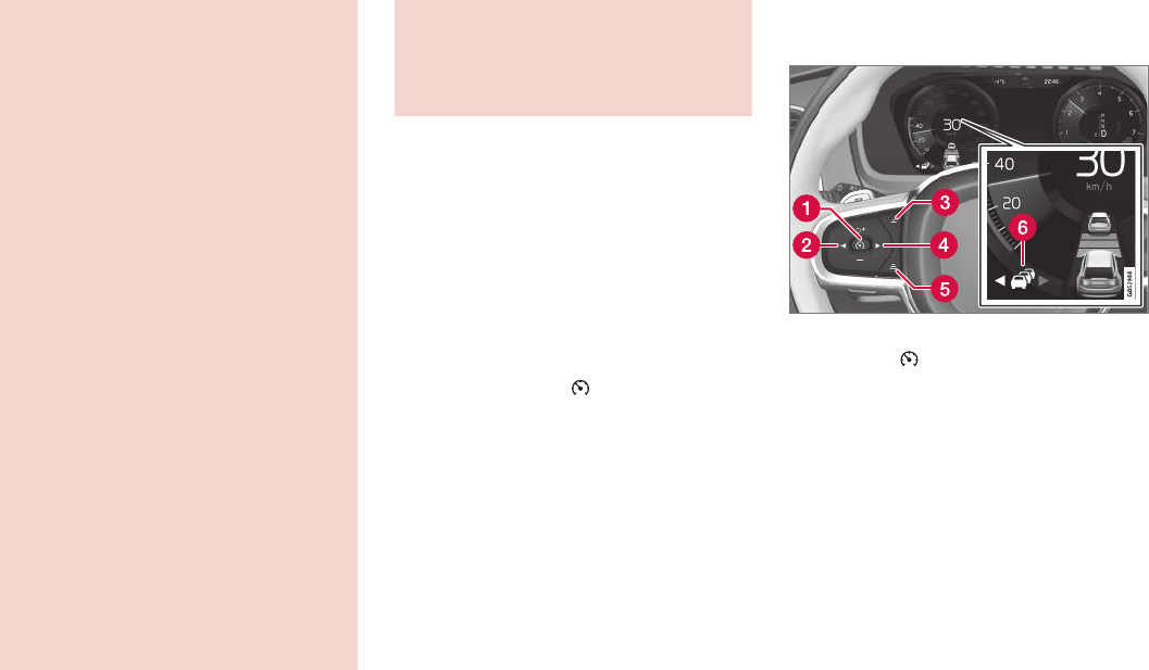
DRIVER SUPPORT
}}
* Option/accessory, for more information, see Introduction. 267
rain or snow, in poor visibility, on winding
roads or on highway on- or off-ramps.
•Pilot Assist uses the vehicle's camera
and radar sensor, which have limitations.
Pilot Assist may deactivate or not function
optimally if:
•the lane's side market lines are missing,
badly faded or cross each other.
•the division of lanes is not clear, e.g.,
when a line divides or merges with
another, at exits or if there are many road
signs/markers.
•if there are edges or other lines on or
near the lane, e.g., curbs, cracks, repaired
areas, sharp shadows, etc.
•the lane is narrow or winding.
•the weather conditions (rain, snow, fog,
slush, poor visibility, backlighting, etc).
The driver should also be aware that Pilot
Assist has the following limitations:
•High curbs, barriers and temporary obsta-
cles (cones, barriers etc) may not be
detected or could be detected incorrectly
as side marker lines, which may create a
risk of collision. The driver must ensure a
safe distance to these obstacles.
•The camera or radar sensor may not be
able to detect objects if there are pot-
holes or if there are stationary objects
partially or completely blocking the road.
•Pilot Assist does not "see" pedestrians,
animals, etc.
•Pilot Assist's steering capacity is limited
and may not always be able to help the
driver keep the vehicle in the lane.
Hands on the steering wheel
Pilot Assist only functions when the driver's
hands are on the steering wheel, which is con-
tinuously monitored by the system. If this is not
the case, the driver will be alerted by a text mes-
sage in the instrument panel. If the driver's hands
are not returned to the steering wheel, an audible
signal will sound.
If the driver does not return his/her hands to the
steering wheel after the audible signal, Pilot
Assist will go into standby mode and must be
reactivated by pressing .
Related information
•Pilot Assist* (p. 263)
Deactivating/resuming Pilot Assist
Putting Pilot Assist in standby mode
Function buttons and symbols
1. Press the button (1).
> Pilot Assist will go into standby mode.
2. Press the ◀ button (2).
> Pilot Assist will be turned off and shift to
ACC in standby mode.
or
–Press the ◀ button (2).
> Pilot Assist will be turned off and switch
to ACC in active mode.
||
DRIVER SUPPORT
* Option/accessory, for more information, see Introduction.
268
Standby mode due to driver action
If a turn signal is used or if the accelerator pedal
is pressed, Pilot Assist will temporarily go into
standby mode. When the turn signal is switched
off or the accelerator pedal is released, Pilot
Assist will reactivate automatically.
Automatic reactivation from standby mode can be
done within 1 minute. After 1 minute has
elapsed, Pilot Assist must be reactivated man-
ually by pressing the button.
Pilot Assist will temporarily go into standby mode
if:
•the brakes are applied
•the gear selector is moved to the N position.
The driver will then have to regulate speed and
distance to the vehicle ahead, or reactivate Pilot
Assist manually by pressing the button on
the left-side steering wheel keypad.
Automatic standby mode
Pilot Assist interacts with other systems, such as
Electronic Stability Control. If any of these other
systems are not functioning properly, Pilot Assist
will automatically be deactivated.
WARNING
If this happens, the driver will be alerted by an
audible signal and a message in the instru-
ment panel. The driver will have to adapt the
vehicle's speed, apply the brakes when nec-
essary and keep a safe distance to the vehicle
ahead.
Pilot Assist switches automatically to standby
mode if:
•the camera cannot detect the traffic lane's
side marker lines
•the vehicle ahead is not within a reasonable
(detectable) distance
•the driver's hands are not on the steering
wheel
•the driver unbuckles the seat belt
•engine speed (rpm) is too high/low
•the wheels lose traction
•brake temperature is too high
•The camera lens/radar sensor is covered by
e.g., wet snow or if heavy rain interferes with
radar waves
Reactivating Pilot Assist from standby
mode
–Press the button (1).
> The most recently set speed will be used.
Related information
•Pilot Assist* (p. 263)
Setting a Pilot Assist time interval
Different time intervals to the vehicle ahead can
be selected and are shown in the instrument
panel as 1–5 horizontal bars.
Changing the time interval
The greater the number of bars,
the longer the time interval.
One bar between the vehicles
represents a time interval of
approximately 1 second; 5 bars
is approximately 3 seconds.
The same symbol appears if Distance Alert is
activated.
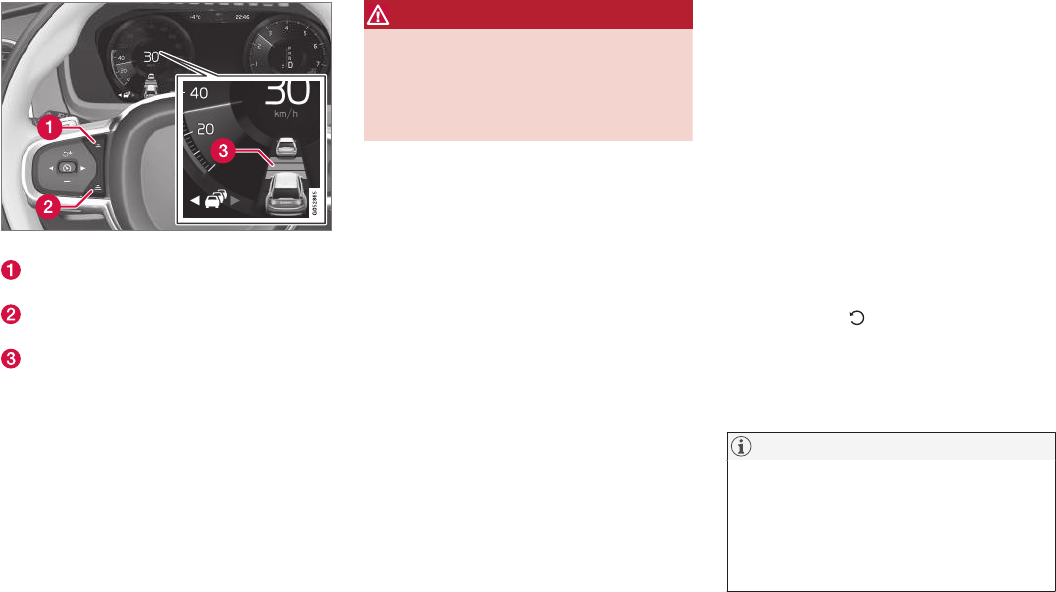
DRIVER SUPPORT
}}
* Option/accessory, for more information, see Introduction. 269
Time interval controls
Press to reduce the time interval to the vehi-
cle ahead
Press to increase the time interval to the
vehicle ahead
Distance indicator
In order to follow the vehicle ahead as smoothly
as possible, Pilot Assist allows the time interval to
vary considerably in certain situations. At low
speeds, when the distance to the vehicle ahead
is short, Pilot Assist increases the time interval
slightly.
•If Pilot Assist does not seem to react when it
is put in active mode, this may be because
the set time interval to the vehicle ahead
does not allow an increase in speed.
•The higher the speed, the greater the dis-
tance to the vehicle ahead for a given time
interval.
WARNING
•Only use a time interval that is suitable in
current traffic conditions.
•A short time interval gives the driver lim-
ited reaction time if an unexpected situa-
tion occurs in traffic.
Related information
•Pilot Assist* (p. 263)
Pilot Assist auto-hold brake
function
At certain speeds, Pilot Assist provides braking
effect.
Stop-and-go driving
During brief stops in slow-moving traffic or att
traffic lights where the vehicle is not stopped for
more than 3 seconds, driving will resume auto-
matically. If it takes more than 3 seconds for the
vehicle ahead to begin moving again, Pilot Assist
will go into standby mode and the auto-hold
brake function will activate.
The driver will then have to reactivate Pilot Assist
as follows:
–•Press the button
•Press the accelerator pedal
> Pilot Assist will resume following the vehi-
cle ahead if it begins to move within
approx. 6 seconds.
NOTE
•Pilot Assist can keep the vehicle station-
ary for max. 5 minutes, after which the
parking brake will be set and Pilot Assist
will go into standby mode.
•The parking brake must be released
before Pilot Assist can be reactivated.
||
DRIVER SUPPORT
* Option/accessory, for more information, see Introduction.
270
Deactivating the auto-hold brake
function
In certain situations, auto-hold will be deactivated
when the vehicle is at a standstill and Pilot Assist
will go into standby mode.
This means that the brakes will be released
and the vehicle can begin to roll.
The driver must actively apply the brakes to keep
the vehicle at a standstill.
This can occur in the following situations:
•the driver presses the brake pedal
•the parking brake is set
•the gear selector is moved to the P, N or R
positions
•the driver puts Pilot Assist in standby mode
Automatically setting the parking brake
In certain situations, the parking brake is set
automatically to help keep the vehicle at a stand-
still.
This occurs if:
•the driver unbuckles the seat belt or opens
the door
•Pilot Assist has kept the vehicle at a stand-
still for more than approx. 5 minutes
•the engine is turned off
•the brakes overheat
Related information
•Pilot Assist* (p. 263)
Pilot Assist limitations
Pilot Assist functionality may be limited in certain
situations.

DRIVER SUPPORT
* Option/accessory, for more information, see Introduction. 271
WARNING
•Pilot Assist is not a collision avoidance
system. The driver is always responsible
for applying the brakes if the system does
not detect another vehicle.
•Do not use Pilot Assist in demanding
driving conditions such as city driving or
other heavy traffic situations, in slippery
conditions, when there is a great deal of
water or slush on the road, during heavy
rain or snow, in poor visibility, on winding
roads or on highway on- or off-ramps.
•Pilot Assist uses the vehicle's camera
and radar sensor, which have limitations.
Pilot Assist may deactivate or not function
optimally if:
•the lane's side market lines are missing,
badly faded or cross each other.
•the division of lanes is not clear, e.g.,
when a line divides or merges with
another, at exits or if there are many road
signs/markers.
•if there are edges or other lines on or
near the lane, e.g., curbs, cracks, repaired
areas, sharp shadows, etc.
•the lane is narrow or winding.
•the weather conditions (rain, snow, fog,
slush, poor visibility, backlighting, etc).
The driver should also be aware that Pilot
Assist has the following limitations:
•High curbs, barriers and temporary obsta-
cles (cones, barriers etc) may not be
detected or could be detected incorrectly
as side marker lines, which may create a
risk of collision. The driver must ensure a
safe distance to these obstacles.
•The camera or radar sensor may not be
able to detect objects if there are pot-
holes or if there are stationary objects
partially or completely blocking the road.
•Pilot Assist does not "see" pedestrians,
animals, etc.
•Pilot Assist's steering capacity is limited
and may not always be able to help the
driver keep the vehicle in the lane.
The driver can always take action to override Pilot
Assist.
Steep roads and/or heavy loads
Pilot Assist is primarily intended for use on rela-
tively level roads. The function may not be able to
maintain the correct time interval to the vehicle
ahead on when driving down steep hills, when the
vehicle is transporting a heavy load or if it is tow-
ing a trailer. The driver should be attentive and
prepared to apply the brakes in these situations.
Related information
•Radar sensor limitations (p. 248)
•Pilot Assist* (p. 263)
•Starting and activating Pilot Assist (p. 266)
•Setting a Pilot Assist time interval (p. 268)
•Deactivating/resuming Pilot Assist (p. 267)
•Pilot Assist auto-hold brake function (p. 269)
•Camera limitations (p. 244)
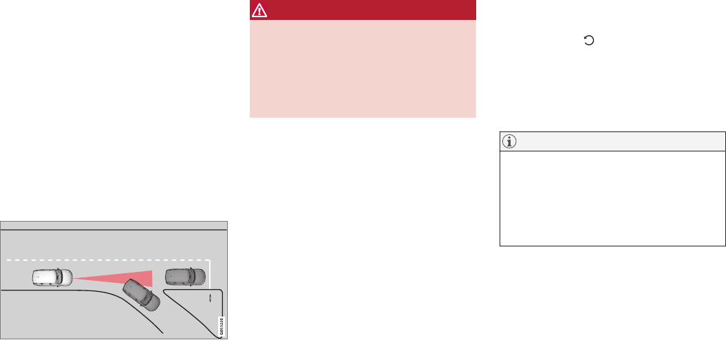
DRIVER SUPPORT
272
Other Adaptive Cruise Control
(ACC) functions
ACC is an optional system designed to assist
the driver by maintaining a set speed or a set
time interval to the vehicle ahead.
ACC has several supplementary functions:
•Changing target vehicles
•Automatic standby mode when changing tar-
gets
•Auto-hold brake function
•Deactivation of the auto-hold brake function
•Automatically setting the parking brake
Changing target vehicles
If the target vehicle turns suddenly, there may be a sta-
tionary vehicle ahead
When ACC is actively following another vehicle at
speeds under 20 mph (30 km/h) and changes
targets from a moving vehicle to a stationary one,
the system will brake for the stationary vehicle.
WARNING
If ACC changes targets from a moving vehicle
to a stationary one at speeds above 20 mph
(30 km/h), the system will not react to the
stationary vehicle and will accelerate to the
previously set speed.
The driver must actively apply the brakes to
slow/stop the vehicle.
Automatic standby mode when changing
targets
ACC disengages and goes into standby mode if:
•your vehicle's speed goes below approx. 3
mph (5 km/h) and ACC cannot determine if
the target object is a stationary vehicle or
some other type of object such as a speed
bump, etc
•the vehicle's speed goes below approx.
3 mph (5 km/h) and the vehicle ahead
changes lanes or turns so that ACC no
longer has a target vehicle to follow
Auto-hold brake function
In slow-moving, stop-and-go traffic or when stop-
ped at a traffic light, driving will resume automati-
cally if the vehicle is not stopped for more than
approx. 3 seconds. If it takes more than
3 seconds for the vehicle ahead to begin moving
again, ACC will go into standby mode and the
auto-hold brake function will activate.
–The driver will then have to reactivate ACC in
one of the following ways:
•Press the button on the left-side
steering wheel keypad
•Press the accelerator pedal
> ACC will resume following the vehicle
ahead (target vehicle) if it begins to move
within approx. 6 seconds.
NOTE
ACC can keep the vehicle at a standstill for
up to 5 minutes, after which the parking brake
will be set and ACC will go into standby
mode.
The parking brake has to be released before
ACC can be reactivated.
DRIVER SUPPORT
* Option/accessory, for more information, see Introduction. 273
Deactivation of the auto-hold brake function
In certain situations, auto-hold will be deactivated
when the vehicle is at a standstill and ACC will go
into standby mode.
This means that the brakes will be released and
the vehicle can begin to roll.
The driver must actively apply the brakes to keep
the vehicle at a standstill.
This can occur in the following situations:
•the driver presses the brake pedal
•the parking brake is set
•the gear selector is moved to the P, N or R
positions
•the driver puts ACC in standby mode
Automatically setting the parking brake
In certain situations, the parking brake is set
automatically to help keep the vehicle at a stand-
still.
This occurs if:
•the driver unbuckles the seat belt or opens
the door
•ACC has kept the vehicle at a standstill for
more than approx. 5 minutes
•the engine is turned off
•the brakes overheat
Related information
•Adaptive Cruise Control (ACC)* (p. 256)
•Auto-hold brake function (p. 338)
•Parking brake (p. 341)
Radar sensor
The radar sensor is used by several driver sup-
port functions to help detect other vehicles.
The radar sensor is used by the following func-
tions:
•Distance Alert*
•Adaptive Cruise Control*
•Pilot Assist*
•City Safety*
Modification of the radar sensor could make its
use illegal.
Related information
•Radar sensor - type approval (p. 274)
•Radar sensor limitations (p. 248)

DRIVER SUPPORT
* Option/accessory, for more information, see Introduction.
274
Radar sensor - type approval
USA & Canada:
FCC ID: L2C0054TR IC: 3432A-0054TR FCC
ID: L2C0055TR IC: 3432A-0055TR
This device complies with Part 15 of the FCC
Rules and with Industry Canada license-exempt
RSS standard(s). Operation is subject to the fol-
lowing two conditions:
(1) This device may not cause harmful interfer-
ence, and
(2) This device must accept any interference
received, including interference that may cause
undesired operation.
WARNING
Changes or modifications not expressively
approved by the party responsible for compli-
ance could void the user's authority to oper-
ate the equipment.
The term “IC:” before the radio certification num-
ber only signifies that Industry Canada technical
specifications were met.
Related information
•Radar sensor (p. 273)
Adaptive cruise control passing
assistance
ACC can assist the driver when passing other
vehicles.
How passing assistance works
When ACC is following another vehicle and the
driver indicates that he/she is about to pass that
vehicle by using the left turn signal, ACC will
begin accelerating toward the vehicle ahead
before your vehicle has moved into the passing
lane.
The function will then delay a speed reduction to
avoid early braking as your vehicle approaches
the slower-moving vehicle.
The function is active until your vehicle has
passed the other vehicle.
WARNING
Be aware that this function may be activated
in situations other than when passing a vehi-
cle, such as if the turn signal is used to indi-
cate a lane change or to indicate a turn. The
vehicle will accelerate briefly.
Using passing assistance
To activate passing assistance:
•Your vehicle (ACC) must be following
another vehicle (the target vehicle).
•Current speed must be at least approx.
45 mph (70 km/h ).
•The speed set for ACC must be high enough
to safely pass the vehicle ahead.
Starting passing assistance
To start a passing assistance sequence:
•Activate the left turn signal.
Passing assistance limitations
WARNING
The driver should be prepared for sudden
changes when passing assistance is used. In
certain cases, there may be undesired accel-
eration.
Certain situations should be avoided, such as:
•If the vehicle is approaching an exit to the
left or a left turn.
•If the vehicle ahead slows down before
your vehicle has moved into the passing
lane.
•Traffic in the passing lane slows down.
Passing assistance in these situations can be
deactivated by putting ACC in standby mode.
Related information
•Adaptive Cruise Control (ACC)* (p. 256)

DRIVER SUPPORT
* Option/accessory, for more information, see Introduction. 275
Adaptive Cruise Control (ACC) -
fault tracing
ACC is an optional system designed to assist
the driver by maintaining a set speed or a set
time interval to the vehicle ahead.
If this symbol is displayed in the instru-
ment panel and the message
Windscreen sensor Sensor
blocked, see Owner's manual
appears, the ACC radar sensor is blocked and
cannot detect vehicles ahead.
This message also indicates that the following
systems may have reduced functionality:
•Distance Alert
•City Safety
•Driver Alert Control
•Pilot Assist
•Lane Departure Warning (LDW)
•Lane Keeping Aid (LKA)
•Traffic Sign Information (TSI)
The following table lists possible causes for this
message being displayed and suitable actions:
Cause Action
The windshield in front of the radar is dirty or covered with snow/ice. Clean/clear the windshield in front of the radar.
Heavy rain or snow is interfering with the radar signals. No action possible. Heavy precipitation may affect the function of the radar.
Swirling water or snow from the surface of the road may interfere with the
radar signals.
No action possible. A very wet or snow-covered road surface may affect the
function of the radar.
The windshield in front of the radar is clean but the message remains in the
display.
Wait a short time. It may take several minutes for the radar to detect that it is
no longer obstructed.
A text message can be erased by briefly pressing
the O button on the right-side steering wheel
keypad. If the message recurs, contact a trained
and authorized Volvo service technician or
retailer.
Related information
•Adaptive Cruise Control (ACC)* (p. 256)
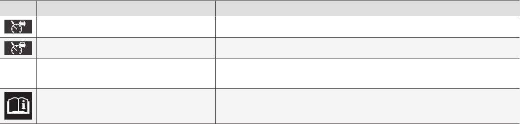
DRIVER SUPPORT
* Option/accessory, for more information, see Introduction.
276
Adaptive Cruise Control (ACC)
symbols and messages
In certain cases, ACC will display symbols (in
different colors) and text messages.
The following table lists several ACC-related
symbols and messages.
Symbol Message Explanation
WHITE symbol ACC is in active mode and maintaining the set speed.
GRAY symbol and Unavailable ACC is in standby mode.
Adaptive cruise
Service required
The system is not functioning properly. Contact a trained and qualified Volvo Service tech-
nician.
Windscreen sensor Sensor blocked, see
Owner's manual
Clean the windshield in front of the camera/radar sensor.
Related information
•Adaptive Cruise Control (ACC)* (p. 256)
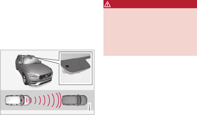
DRIVER SUPPORT
}}
277
City Safety™
City Safety™ is a support system designed to
help alert the driver to pedestrians, cyclists and
vehicles that may appear suddenly in front of
your vehicle. Visual and audible alerts are provi-
ded. The vehicle will brake automatically if the
driver is unable to react quickly enough.
City Safety introduction
Location of the camera and radar sensor
City Safety can help prevent a collision or lower
the vehicle's speed at the point of impact.
WARNING
•City Safety™ is a supplemental aid to the
driver. It can never replace the driver’s
attention to traffic conditions or his/her
responsibility for operating the vehicle in
a safe manner.
•City Safety™ does not function in all driv-
ing situations or in all traffic, weather or
road conditions.
The City Safety function can help the driver avoid
a collision when e.g., there is a sudden change in
the traffic ahead if the driver's does not take
action.
The function assists the driver by applying the
brakes automatically if there is an imminent risk
of a collision and the driver does not react in
time.
City Safety triggers brief, forceful braking in an
attempt to stop your vehicle immediately behind
the vehicle or object ahead. This braking may be
perceived as being very sudden.
City Safety activates in situations where the driver
has not applied the brakes in time, which means
that the system cannot help the driver in all situa-
tions.
City Safety is designed to intervene as late as
possible to help avoid unnecessary activation.
Normally, the occupants of the vehicle will not be
aware of City Safety except when the system
intervenes when a collision is imminent.
City Safety parameters
City Safety can help avoid a collision with a vehi-
cle or cyclist ahead by reducing your vehicle's
speed by up to 30 mph (50 km/h). In the case of
pedestrians, City Safety can reduce speed by up
to 28 mph (45 km/h).
If the difference in speed between your vehicle
and the vehicle ahead/pedestrian is greater than
30 mph (50 km/h) or 28 mph (45 km/h) respec-
tively, City Safety's auto-brake function cannot
prevent a collision but it can help mitigate effects
of the collision.
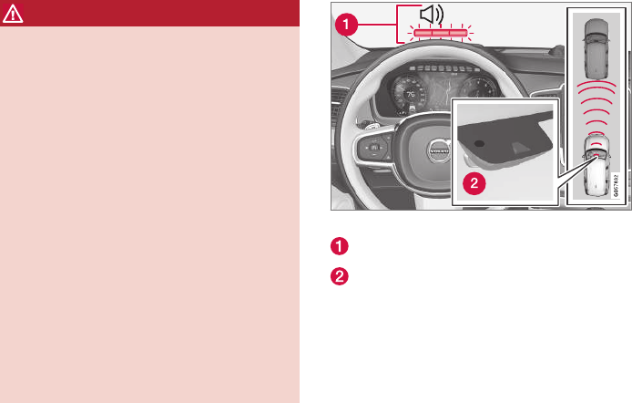
||
DRIVER SUPPORT
278
WARNING
Warnings will only be provided if there is an
imminent risk of a collision taking place. The
driver should be aware of the system's limita-
tions before operating the vehicle.
Warnings and automatic braking for pedes-
trians and cyclists are deactivated at speeds
above 50 mph (80 km/h).
City Safety's auto-brake function can help
prevent a collision or reduce the speed at
which a collision occurs. However, the driver
should always apply the brakes, even if auto-
brake is operating.
The driver is always responsible for maintain-
ing the correct speed and distance in relation
to the vehicle ahead. Never wait for a collision
warning or for City Safety to intervene.
City Safety does not activate the auto-brake
function during fast acceleration.
City Safety maintenance may only be carried
out by a trained and qualified Volvo service
technician.
Function overview
Audio-visual collision warning
Distance monitoring by a camera and radar
sensor
When triggered, City Safety carries out three
steps in the following order:
1. Collision warning
2. Brake assistance
3. Auto-brake
1: Collision warning
The driver is first alerted to the risk of an immi-
nent collision.
City Safety can detect pedestrians, cyclists or
vehicles that are stationary, are moving in the
same direction as your vehicle or are described in
the article "City Safety in crossing traffic." The
driver is alerted by a flashing red warning signal,
an audible signal and pulsations in the brake
pedal.
2: Brake assistance
If the risk of a collision increases, brake support
will be activated.
This function increases pressure on the brake
pedal if the driver does not apply enough pres-
sure to the pedal.
3: Auto-brake
The brakes will be applied automatically.
If the driver has not taken action at this stage and
a collision is imminent, auto-braking will be trig-
gered. Full braking effect will be used to avoid
the collision if possible or to make the speed at
the point of impact as low as possible.
In certain situations, auto-braking may begin with
limited effect before full braking is used.
If City Safety has prevented a collision, the vehi-
cle will be kept at a standstill until the driver
takes action. If the vehicle has slowed to avoid
colliding with the vehicle ahead, your speed will
be reduced to that vehicle's speed.
When auto-break is triggered, the seat belt pre-
tensioners may also be activated, see the article
"Seat belts" for additional information.
Auto-braking can be cancelled if the driver
presses hard on the accelerator pedal.
DRIVER SUPPORT
}}}}
279
When City Safety applies the brakes, the brake
lights will illuminate.
When City Safety is triggered and applies the
brakes, a text message will be displayed in the
instrument panel.
Related information
•City Safety™ troubleshooting (p. 285)
•City Safety in crossing traffic (p. 281)
•City Safety limitations (p. 283)
•City Safety symbols and messages (p. 287)
•Detecting cyclists and pedestrians with City
Safety (p. 280)
•Rear Collision Warning (RCW) (p. 282)
•City Safety warning level settings (p. 279)
•City Safety in crossing traffic (p. 281)
•Seat belts (p. 60)
City Safety warning level settings
City Safety is always activated but the function's
warning distance can be adjusted.
NOTE
City Safety cannot be turned off and activates
automatically each time the engine/electric
motor is started.
Setting a warning level (distance)
The distance set for warnings determines the
system's responsiveness and sets the distance at
which visual, audible and tangible (haptic) warn-
ings will be triggered.
To do so:
1. Tap Settings in the center display's Top
view.
2. Tap My Car IntelliSafe City Safety.
3. Choose among Earlier, Normal or Later.
Begin by choosing Earlier. If too many warnings
are given, change to Normal.
If the driver feels that warnings are given too
often, the warning level can be lowered. This
means that warnings will be provided later, result-
ing in fewer warnings being given.
The setting Later should only used in exceptional
circumstances, e.g., for a more dynamic driving
style.
WARNING
•No automatic system can be guaranteed
to function 100% correctly in all situa-
tions. For that reason, never test City
Safety by driving toward a person or
object. This could result in serious injury
or death.
•Even if the setting Earlier has been
selected, warnings may be perceived as
being given late, e.g., if the difference in
speed is great or if the vehicle ahead
brakes suddenly.
•City Safety can provide a warning for a
potential collision but it can never shorten
the driver's reaction time.
•To help make City Safety as effective as
possible, always using the setting Earlier
is recommended.
NOTE
•Due to local traffic regulations in certain
markets, RCW will not activate the rear
turn signals. That part of the function will
be deactivated.
•The use of the rear turn signals will also
be deactivated if the City Safety warning
level is set at Later. See also the section
"Setting a warning level (distance)" in the
article "City Safety settings."
•If RCW detects a vehicle approaching
from behind, the seat belt pretensioners

||
DRIVER SUPPORT
280
and Whiplash Protection System will be
activated.
Related information
•City Safety limitations (p. 283)
•City Safety™ (p. 277)
•Rear Collision Warning (RCW) (p. 282)
Detecting cyclists and pedestrians
with City Safety
City Safety can detect vehicles, cyclists and
pedestrians.
Vehicles
City Safety detects most types of vehicles that
are either stationary, moving in the same direc-
tion as your vehicle or approaching when you are
about to turn left.
In order for City Safety to detect a vehicle in
darkness, its headlights and taillights must be on
and clearly visible.
Cyclists
Optimal example of what the system considers to be a
cyclist: clear body/bike contours
To help function optimally, City Safety's function
for cyclist detection needs clear information
about the bike itself and the rider's head, arms,
shoulders, legs, the upper and lower parts of the
body and a cyclist's normal pattern of movement.
•If major parts of the cyclist's body are not
visible to the camera, the system cannot
detect the cyclist.
•The cyclist must be an adult riding a bike
intended for an adult.
WARNING
City Safety is designed to be a supplementary
driving aid.
It cannot detect:
•all cyclists in all situations, e.g., a partially
obscured cyclist will not be detected.
•a cyclist whose clothing prevents a clear
view of the person's body contours.
•a cyclist transporting a large object.
The driver is always responsible for operating
the vehicle in a safe manner.
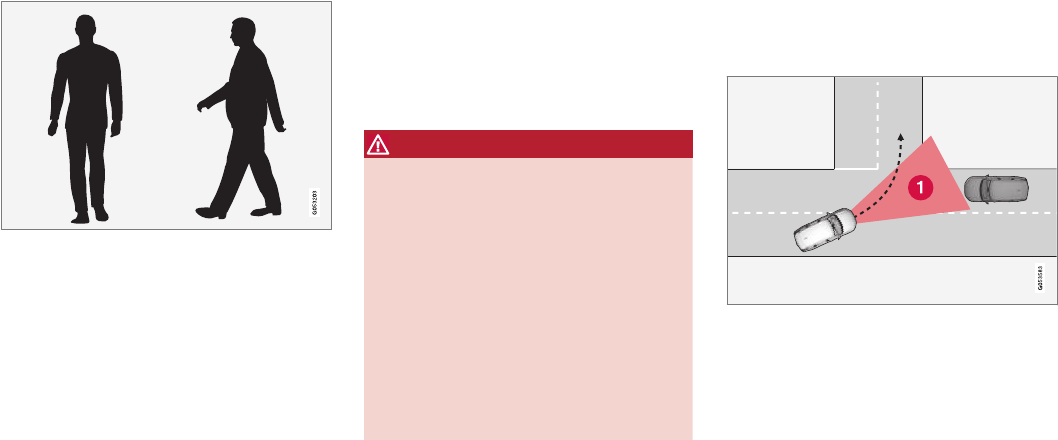
DRIVER SUPPORT
}}
281
Pedestrians
Optimal example of what the system considers to be a
pedestrian: clear body contours
To help function optimally, City Safety's function
for pedestrian detection needs clear information
about the person's head, arms, shoulders, legs,
the upper and lower parts of the body and a per-
son's normal pattern of movement.
In order to detect a pedestrian, there must be a
contrast to the background. If there is little con-
trast, the person may be detected late or not at
all, which may result in a late or no reaction from
the system.
City Safety can also detect pedestrians in dark-
ness with the help of the vehicle's headlights.
•If major parts of the pedestrian's body are
not visible to the camera, he/she may not be
detected.
•In order to detect a pedestrian, the system
must have a full view of the person's entire
body and the person must be at least 32 in.
(80 cm) tall.
WARNING
City Safety is designed to be a supplementary
driving aid.
It cannot detect pedestrians:
•who are partially obscured, wearing cloth-
ing that prevents a clear view of the per-
son's body contours or who are not at
least 32 in. (80 cm) tall.
•who have limited contrast to their immedi-
ate background. A warning or braking
may be delayed or not come at all.
•carrying a large object.
The driver is always responsible for operating
the vehicle in a safe manner.
Related information
•City Safety™ (p. 277)
•City Safety limitations (p. 283)
•City Safety in crossing traffic (p. 281)
City Safety in crossing traffic
City Safety can help the driver when making a
left turn in an intersection.
Turning at an intersection
1. The area in which City Safety can detect an oncoming
vehicle
In order for City Safety to detect an approaching
vehicle in situations where there is a risk of a col-
lision, that vehicle must be within City Safety's
range (the red area in the illustration).
The following criteria must also be met:
•your vehicle's speed must be at least 3 mph
(4 km/h)
•the approaching vehicle's headlights must be
on

||
DRIVER SUPPORT
282
WARNING
•City Safety is a supplementary driving aid
and does not function in all driving situa-
tions or in all traffic, weather or road con-
ditions.
•Warnings and braking for an approaching
vehicle will usually come at a very late
stage.
•The driver is responsible for maintaining a
safe distance and speed. Never wait for a
warning or for City Safety to take action.
Limitations
In certain situations, it may be very difficult for
City Safety to help the driver avoid a collision with
an approaching vehicle in crossing traffic, for
example:
•on slippery roads when Electronic Stability
Control is active
•if the approaching vehicle is detected at a
late stage
•If the approaching vehicle is partially
obscured by another vehicle
•if the approaching vehicle moves erratically
(e.g., sudden lane changes at a late stage)
Related information
•City Safety™ (p. 277)
•City Safety limitations (p. 283)
Rear Collision Warning (RCW)
The Rear Collision Warning with braking at
standstill (RCW) function can help the driver
avoid rear-end collisions.
RCW is activated automatically each time the
engine is started and cannot be turned off.
RCW can warn the driver of a vehicle approach-
ing yours from behind by rapidly flashing your
rear turn signals.
RCW is only activated when a vehicle is rapidly
approaching your vehicle from behind.
At speeds below 20 mph (30 km/h), if RCW
determines that your vehicle is at risk of a rear-
end collision, the front seat belt pretensioners
and the Whiplash Protection System are acti-
vated.
Just prior to the collision, the brakes are also
applied to help reduce your vehicle's forward
movement if and when the collision occurs. How-
ever, this can only happen if your vehicle is sta-
tionary.
The brakes will be released immediately if the
accelerator pedal is pressed.
NOTE
•Due to local traffic regulations in certain
markets, RCW will not activate the rear
turn signals. That part of the function will
be deactivated.
•The use of the rear turn signals will also
be deactivated if the City Safety warning
level is set at Later. See also the section
"Setting a warning level (distance)" in the
article "City Safety settings."
•If RCW detects a vehicle approaching
from behind, the seat belt pretensioners
and Whiplash Protection System will be
activated.
Limitations
In some circumstances, it may be difficult for
RCW to help the driver if there is a risk of a colli-
sion, such as:
•In slippery conditions when Electronic
Stability Control is active
•If the vehicle approaching from the rear is
detected at a late stage
•If the vehicle approaching from the rear
changes lanes at a late stage
•If the vehicle approaching from the rear is
moving at a speed above approx. 50 mph
(80 km/h)

DRIVER SUPPORT
}}
283
Related information
•City Safety™ (p. 277)
•Whiplash protection system (p. 59)
•Seat belts (p. 60)
•City Safety warning level settings (p. 279)
City Safety limitations
City Safety™ may have limited or reduced func-
tionality in certain situations.
The function has several limitations that the driver
should be familiar with:
Low objects
Hanging objects, such as flags for overhanging
loads or accessories such as auxiliary lights or
front protective grids that extend beyond the
height of the hood may limit City Safety's func-
tion.
Slippery driving conditions
The extended braking distance on slippery roads
may reduce City Safety's capacity to help avoid a
collision. In situations of this type, the ABS
brakes and Electronic Stability Control will help
provide braking power and stability.
Backlighting
Strong sunlight, reflections, extreme light con-
trasts, the use of sunglasses, or if the driver is not
looking straight ahead may make the visual warn-
ing signal in the windshield difficult to see.
Heat
If the temperature in the passenger compartment
is very high, the camera and radar sensor may be
temporarily turned off for approx. 15 minutes
after the engine has been started to protect their
electronic components. When the temperature
has cooled sufficiently, the camera and radar
sensor will restart automatically.
The visual warning signal may also be temporarily
disabled due to high passenger compartment
temperatures caused by strong sunlight.
Warnings may not be given if the distance to the
vehicle ahead is short and the driver is actively
operating the vehicle (clearly depressing a pedal
or turning the steering wheel).
Reduced visibility
City Safety's functions may be greatly impeded or
deactivated by e.g., intense snowfall or rain, in
dense fog, in very dusty conditions or if there is
blowing snow in front of the vehicle. Condensa-
tion, ice, snow or dirt on the windshield may also
reduce the system's functionality.
NOTE
•Keep the windshield in front of the radar
sensor free of ice, snow, dirt, etc.
•Snow or ice on the hood deeper than
2 inches (5 cm) may obstruct the sensor.
Keep the hood free of ice and snow.
•Do not mount or in any way attach any-
thing on the windshield that could
obstruct the radar sensor.

||
DRIVER SUPPORT
284
Camera and radar sensor's field of vision
The camera and radar sensor have limited fields
of vision. In some situations they may detect a
vehicle, pedestrian or cyclist later than expected
or not detect them at all.
Other vehicles that are dirty may be detected
later than others and in dark conditions, motorcy-
cles may be detected late or not at all.
If a text message is displayed in the instrument
panel indicates that the camera or radar sensor
are blocked, it may be difficult for City Safety to
detect a vehicle, pedestrian or cyclist and the
system's functionality may be reduced.
WARNING
Text messages may not be displayed in all sit-
uations in which the camera and/or radar
sensor are blocked. It is therefore essential to
keep the windshield in front the camera/radar
sensor clean and free from snow, ice, etc.
Camera and radar sensor components should
only be serviced or replaced by a trained and
qualified Volvo service technician.
Other limitations
City Safety uses the vehicle's camera and radar
sensor, which have certain general limitations.
See the articles "Camera limitations" and Radar
sensor limitations" for additional information.
WARNING
•Warnings and braking may be delayed or
not occur at all if traffic, weather or other
conditions prevent the camera and/or
radar sensor from detecting pedestrians,
cyclists or other vehicles correctly.
•Other vehicles can only be detected in
darkness if their headlights and taillights
are clearly visible.
•The sensors have a limited range for
pedestrians and cyclists. The system
functions best at speeds up to 30 mph
(50 km/h). For stationary or slow-moving
vehicles, the system functions best at
speeds up to approx. 43 mph (70 km/h).
•Warnings for stationary or slow-moving
vehicles may be impeded by darkness or
poor visibility.
•Warnings and braking for pedestrians and
cyclists will not be provided at speeds
above approx. 50 mph (80 km/h).
•Do not place, attach or mount any objects
on the inside or outside of the windshield
near or over the sensor. This could affect
the camera-based functions.
Action by the driver
Backing up
City Safety is temporarily deactivated while the
vehicle is backing up.
Low speed
City Safety is not activated at very low speeds
(under approx. 3 mph (4 km/h). This means that
the system will not be triggered if your vehicle
approaches a vehicle ahead, such as when park-
ing.
Active driver
Action by the driver always has priority. For this
reason, City Safety may not react or react later
than expected in situations in which the driver is
actively operating the vehicle, even if a collision is
imminent. This is also done to help eliminate
excessive warnings.
Related information
•City Safety™ (p. 277)
•Adaptive Cruise Control (ACC) - fault tracing
(p. 275)
•City Safety™ troubleshooting (p. 285)
•Camera limitations (p. 244)
•Radar sensor limitations (p. 248)
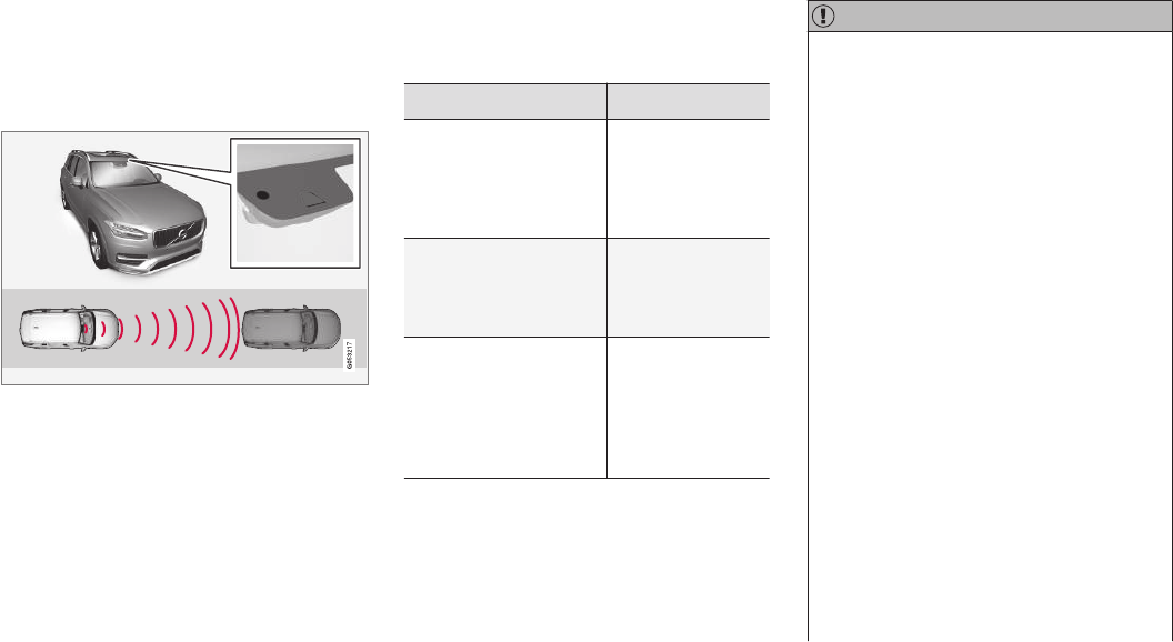
DRIVER SUPPORT
}}}}
285
City Safety™ troubleshooting
Messages pertaining to any possible problems
with City Safety will be displayed in the instru-
ment panel.
Troubleshooting and remedial action
Location of the camera and the radar sensor
If a message is displayed in the instrument panel
saying that the camera/radar sensor is blocked,
City Safety cannot detect vehicles, cyclists or
pedestrians ahead of you, which means that the
system is not functioning properly.
However, this message will not be displayed in all
situations in which the camera/radar sensor is
obstructed. For this reason, the driver must
ensure that the area of the windshield in front of
the camera/radar sensor is always kept clean.
The following table shows some of the situations
that can cause the message to be displayed and
suggested actions.
Cause Action
The area of the wind-
shield in front of the
camera/radar sensor is
dirty or covered by ice or
snow.
Clean the wind-
shield or remove
the ice/ snow.
Thick fog or heavy rain/
snow blocks reduces the
camera/radar sensor's
range of visibility.
No action. The
driver should be
extra alert in condi-
tions of this type.
There is dirt between
the inside of the wind-
shield and the camera/
radar sensor.
Have the area of
the windshield
cleaned by a
trained and quali-
fied Volvo service
technician.
CAUTION
•Service and maintenance on City Safety
may only be carried out by a trained and
qualified Volvo service technician.
•If a crack, scratch or stone chip should
occur in the section of the windshield in
front the camera/radar sensor, contact a
trained and qualified Volvo service techni-
cian to repair or replace the windshield.
Failing to do so may result in reduced
City Safety functionality.
To help prevent limited or reduced functional-
ity, please also observe the following:
•Volvo recommends that cracks, scratches
or stone chips on the windshield in front
of the camera/radar sensor should not
be repaired; in such cases, the entire
windshield should be replaced.
•Before the windshield is replaced, con-
tact a Volvo retailer to ensure that the
correct windshield is ordered and instal-
led. If the wrong type of windshield is
used, this may cause City Safety to func-
tion improperly or not at all.
•Volvo recommends the use of only Genu-
ine Volvo Replacement Windshields.
•When replacing windshield wipers, use
the same type or ones approved by Volvo.

||
DRIVER SUPPORT
* Option/accessory, for more information, see Introduction.
286
After the windshield has been replaced, the
camera/radar sensor will have to be recalibra-
ted by a trained and qualified Volvo service
technician to help ensure proper function of
all of the vehicle's camera-/radar-based sys-
tems.
Maintenance
In order for City Safety to function properly, the
area of the windshield must be kept free of dirt,
ice, snow, etc.
Other vehicle functions
If a message is displayed in the instrument panel,
this means that the other systems using the cam-
era/radar sensor (see the list below) will not have
full functionality or may not function at all.
The radar sensor is used by the following func-
tions:
•Distance Alert*
•Driver Alert Control*
•Adaptive Cruise Control*
•Pilot Assist*
•Road Sign Information*
•Active High Beams*
•Lane Keeping Aid*
Do not mount or in any way attach anything on
the windshield that could obstruct the camera/
radar sensor.
WARNING
•The camera has the same type of limita-
tions as the human eye, i.e., it cannot see
as well in heavy snowfall or rain, thick fog
or in heavy blowing dust or snow. In such
conditions, systems depending on the
camera may experience greatly reduced
functionality or may be temporarily deacti-
vated.
•Never place any objects, decals, etc., on
the windshield in front of the camera. This
could reduce or block the camera’s func-
tion, and could cause one or more of the
systems that utilize the camera to stop
functioning.
•Strong sunlight, reflections from the road
surface, ice or snow covering the road, a
dirty road surface, or unclear lane marker
lines may drastically reduce the camera’s
capacity to detect the side of a lane, a
pedestrian, a cyclist or another vehicle.
Radar sensor for other functions
City Safetyuses the same radar sensor as Adap-
tive Cruise Control. See the article "Radar sensor
limitations" for detailed information.
Related information
•Radar sensor limitations (p. 248)
•Radar sensor (p. 273)
•City Safety limitations (p. 283)

DRIVER SUPPORT
287
City Safety symbols and messages
A number of City Safety-related messages may
be displayed in the instrument panel.
Message Explanation
City Safety
Automatic intervention
When City Safety is braking or has applied the brakes, one of more symbols may illuminate in the instrument
panel and a text message will be displayed.
City Safety
Reduced functionality Service required
The system is not functioning properly. Contact a trained and authorized Volvo service technician.
Related information
•City Safety™ (p. 277)
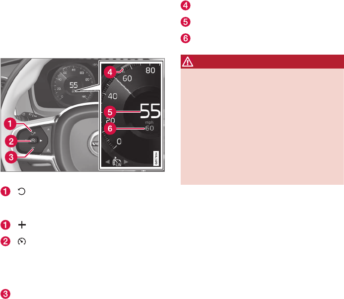
DRIVER SUPPORT
* Option/accessory, for more information, see Introduction.
288
Speed limiter (SL)*
The Speed Limiter (SL) is a feature that helps
prevent the driver from exceeding a preset maxi-
mum speed.
Overview
Function buttons and symbols
SL switches from standby mode to
active mode and the set maximum speed will
be used
Increases the set maximum speed
From standby mode, press to put SL
in active mode and set the current speed as
the maximum or from active mode, press to
put SL in standby mode (the set maximum
speed can be exceeded)
— Decreases the set maximum speed
Set maximum speed indicator
The vehicle's current speed
The set maximum speed
WARNING
•The Speed Limiter cannot cover all driv-
ing situations and traffic, weather and
road conditions.
•The vehicle must always be driven
according to current traffic/road condi-
tions.
•The driver must take action if SL does not
maintain the set maximum speed.
•The driver is always responsible for oper-
ating the vehicle in a safe manner and
observing posted speed limits.
Limitations
On steep downslopes, the Speed limiter's braking
capacity may not be sufficient and the set maxi-
mum speed may be exceeded. If this happens,
Speed limit exceeded will be displayed in the
instrument panel to alert the driver.
This message will appear if the set maximum
speed is exceeded by more than approx. 2 mph
(3 km/h).
Related information
•Starting and activating the Speed Limiter
(SL)* (p. 289)
•Deactivating/reactivating the Speed Limiter*
(p. 293)
•Changing a Speed Limiter (SL)* maximum
speed (p. 289)
•Automatic Speed Limiter (ASL)* (p. 290)
•Activating/deactivating the Automatic Speed
Limiter (ASL)* (p. 291)
•Changing tolerance for the Automatic Speed
Limiter (p. 292)
•Turning the Speed Limiter* off (p. 294)
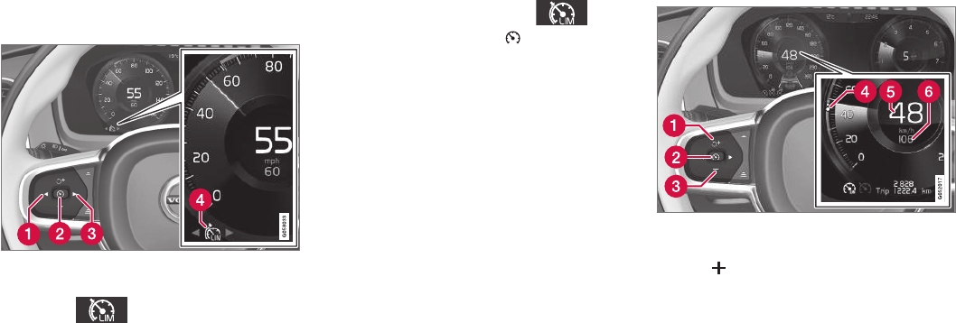
DRIVER SUPPORT
}}
* Option/accessory, for more information, see Introduction. 289
Starting and activating the Speed
Limiter (SL)*
The Speed Limiter (SL) is a feature that has to
be selected and activated in order to set a maxi-
mum speed.
Selecting SL (putting it in standby
mode)
Function buttons and symbols
–Press ◀ (1) or ▶ (3) to scroll to the Speed
Limiter ( ) function.
> The symbol (4) will be displayed in the
instrument panel. This indicates that SL
has been selected and is in standby
mode (no maximum speed has been set).
Activating SL (putting it in active mode
and setting a maximum speed)
The engine must be running before SL can be
put in active mode. The lowest maximum speed
that can be set is 20 mph (30 km/h).
–With SL in standby mode (the will
be displayed), press the button (2).
> This puts SL in active mode and sets the
vehicle's current speed as the maximum
speed.
Related information
•Speed limiter (SL)* (p. 288)
•Deactivating/reactivating the Speed Limiter*
(p. 293)
•Changing a Speed Limiter (SL)* maximum
speed (p. 289)
•Automatic Speed Limiter (ASL)* (p. 290)
•Activating/deactivating the Automatic Speed
Limiter (ASL)* (p. 291)
•Changing tolerance for the Automatic Speed
Limiter (p. 292)
•Turning the Speed Limiter* off (p. 294)
Changing a Speed Limiter (SL)*
maximum speed
The Speed Limiter (SL) is a feature that helps
prevent the driver from exceeding a preset maxi-
mum speed.
Function buttons and symbols
–Change a set maximum speed by pressing
the (1) or — (3) buttons briefly or by
pressing and holding them:
•Press briefly: changes the maximum
speed in +/– 5 mph (+/– 5 km/h) incre-
ments. Each press changes the maximum
speed by +/– 5 mph (+/– 5 km/h).
•Press and hold: changes the maximum
speed +/– 1 mph (+/– 1 km/h) at a time.
Release the button when the indicator (4)
has moved to the desired maximum
speed.
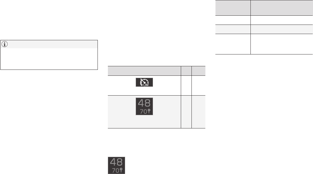
||
DRIVER SUPPORT
* Option/accessory, for more information, see Introduction.
290
Limitations
When driving down steep hills, the Speed
Limiter's braking effect may not be adequate and
the set maximum speed may be exceeded. The
message Speed limit exceeded will appear in
the instrument panel to alert the driver.
NOTE
This message will appear if the maximum
speed is exceeded by more than 2 mph
(3 km/h).
Related information
•Speed limiter (SL)* (p. 288)
Automatic Speed Limiter (ASL)*
The Automatic Speed Limiter (ASL) reads road
signs and adapts the vehicle's maximum speed
to the posted speed limits.
The Speed Limiter function can be switched to
Automatic Speed Limiter.
Is SL or ASL active?
Symbols in the instrument panel indicate which
function is active:
Symbol SL ASL
A
✓ ✓
Sign symbolB after "70": ASL is acti-
vated.
✓
AWHITE symbol: the function is active, GRAY symbol: the func-
tion is in standby mode.
BSee the section "ASL symbol" below for an explanation of the
symbol's different colors.
ASL symbol
A road sign symbol (next to the stored
speed in the center of the speedome-
ter) can be displayed in three different
colors as explained in the following
table:
Road sign
symbol's color
Explanation
Green/yellow ASL is active
Gray ASL is in standby mode
Amber/orange ASL is temporarily in standby
mode (e.g., because a speed
limit sign could not be read)
Limitations
Adjusting a set speed is done first when the vehi-
cle passes a speed limit sign. If a speed limit sign
cannot be read (e.g., because it is twisted, dam-
aged, faded, dirty, covered by snow, etc.) ASL will
go into standby mode because the system will
not have "seen" the speed posted on the sign
(SL will activate). The driver will have to react and
adapt the vehicle's speed. ASL will reactivate
when the vehicle passes a speed limit sign that
the system can read.
Related information
•Speed limiter (SL)* (p. 288)
•Activating/deactivating the Automatic Speed
Limiter (ASL)* (p. 291)
•Changing tolerance for the Automatic Speed
Limiter (p. 292)
•Starting and activating the Speed Limiter
(SL)* (p. 289)
DRIVER SUPPORT
* Option/accessory, for more information, see Introduction. 291
•Deactivating/reactivating the Speed Limiter*
(p. 293)
•Road Sign Information (RSI)* (p. 294)
Activating/deactivating the
Automatic Speed Limiter (ASL)*
ASL is activated/deactivated in
the center display's Function
view.
Activating
1. If SL is not activated, tap the Speed Sign
Assist button1 in the center display's Func-
tion view.
> ASL will go into standby mode and a
green indicator light in the button will illu-
minate. A road sign symbol will be dis-
played in center of the speedometer.
2. Press the button on the left-side steer-
ing wheel keypad.
> ASL will be activated with the vehicle's
current speed.
Deactivating
1. Tap the Speed Sign Assist button in the
center display's Function view.
> ASL will be deactivated and the Speed
limiter (SL) will be activated.
2. Press the button on the left-side steer-
ing wheel keypad.
> SL will go into standby mode.
WARNING
After switching from ASL to SL, the vehicle
will no longer adapt speed to posted speed
limits. It will only limit the vehicle's maximum
speed.
Related information
•Speed limiter (SL)* (p. 288)
•Automatic Speed Limiter (ASL)* (p. 290)
1If this button is tapped while SL is activated, ASL will immediately begin reading road signs.
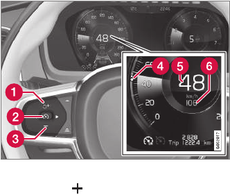
DRIVER SUPPORT
* Option/accessory, for more information, see Introduction.
292
Changing tolerance for the
Automatic Speed Limiter
Posted speed limit tolerance
ASL can be set to allow the vehicle to drive a
maximum of 5 mph (10 km/h) above or below
the posted speed limit. For example, if the current
posted speed limit is 50 mph (70 km/h), the
driver can opt to allow the vehicle to drive at a
speed of 55 mph (80 km/h).
Function buttons and symbols
–Press the button (1) briefly to change
50 mph (70 km/h) to 55 mph (75 km/h) in
the center of the speedometer (6).
> The vehicle will then use the selected tol-
erance if the speed limit sign detected is
50 mph (70 km/h). This will continue until
the vehicle passes a sign with a lower or
higher speed limit. The vehicle will then
adjust to the new maximum speed and
the set tolerance will be deleted from the
system's memory.
The set tolerance can be adjusted in the
same way as the set Speed Limiter's set
maximum speed.
If the Road Sign Information system* is
activated, the posted speed limit will be
indicated by a RED marker (4) on the
speedometer's speed scale.
Related information
•Automatic Speed Limiter (ASL)* (p. 290)
•Activating/deactivating the Automatic Speed
Limiter (ASL)* (p. 291)
•Road Sign Information (RSI)* (p. 294)
•Changing a Speed Limiter (SL)* maximum
speed (p. 289)
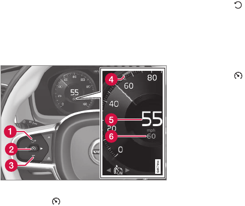
DRIVER SUPPORT
* Option/accessory, for more information, see Introduction. 293
Deactivating/reactivating the Speed
Limiter*
The Speed Limiter (SL) can be temporarily deac-
tivated and put in standby mode.
Deactivating and putting SL in standby
mode
To temporarily put the Speed Limiter in standby
mode:
Function buttons and symbols
–Press the button (2).
> The symbols in the instrument panel will
change colors from WHITE to GRAY.
This indicates that SL is temporarily in
standby mode and will not limit the vehi-
cle's maximum speed.
Reactivating SL from standby mode
To reactivate SL after it has temporarily been put
in standby mode:
–Press the button (1).
> The maximum speed marker (4) and sym-
bols will change colors to WHITE and the
vehicle's maximum speed will be limited to
the previously set maximum speed.
or
–Press the button (2).
> The symbols will change colors from
GRAY to WHITE and the vehicle's current
speed will be set as the maximum speed.
Increasing the speed with the
accelerator pedal
The set maximum speed can be temporarily
exceeded using the accelerator pedal without
putting SL in standby mode, for instance when
quick acceleration is required.
1. Press the accelerator pedal as far down as
possible and release it when the vehicle has
reached the desired speed.
> SL remains activated (the symbols in the
instrument panel will remain WHITE).
2. Release the accelerator pedal when the tem-
porary acceleration is completed.
> The vehicle will slow down and its speed
will remain under the set maximum speed.
Related information
•Speed limiter (SL)* (p. 288)
•Starting and activating the Speed Limiter
(SL)* (p. 289)
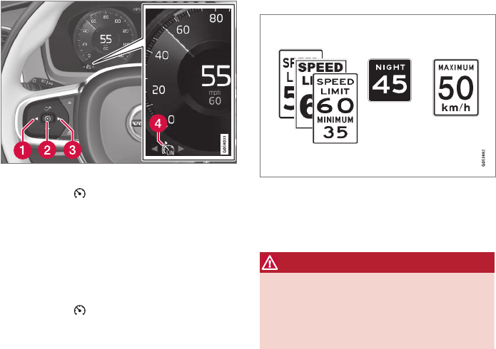
DRIVER SUPPORT
* Option/accessory, for more information, see Introduction.
294
Turning the Speed Limiter* off
The Speed Limiter (SL) can be turned off.
Function buttons and symbols
1. Press the button (2).
> SL will go into standby mode.
2. Press the ◀ (1) or ▶ (3) buttons to select
another function.
> The SL symbol (4) in the instrument panel
will go out and the set maximum speed
will be erased from the system's memory.
3. Press the button (2) again.
> The newly selected function will be acti-
vated.
Related information
•Speed limiter (SL)* (p. 288)
•Starting and activating the Speed Limiter
(SL)* (p. 289)
Road Sign Information (RSI)*
RSI is a feature that helps the driver see road
signs showing the posted speed limit.
Examples of readable road signs
If the vehicle passes a sign showing the speed
limit, this will be displayed in the instrument panel
and the head-up display*.
WARNING
RSI does not function in all situations and is
only intended to provide supplementary infor-
mation.
The driver is always responsible for operating
the vehicle safely.
Related information
•Road Sign Assistance (RSI)* operation
(p. 295)
•Road Sign Assistance (RSI)* limitations
(p. 296)
•Speed limiter (SL)* (p. 288)
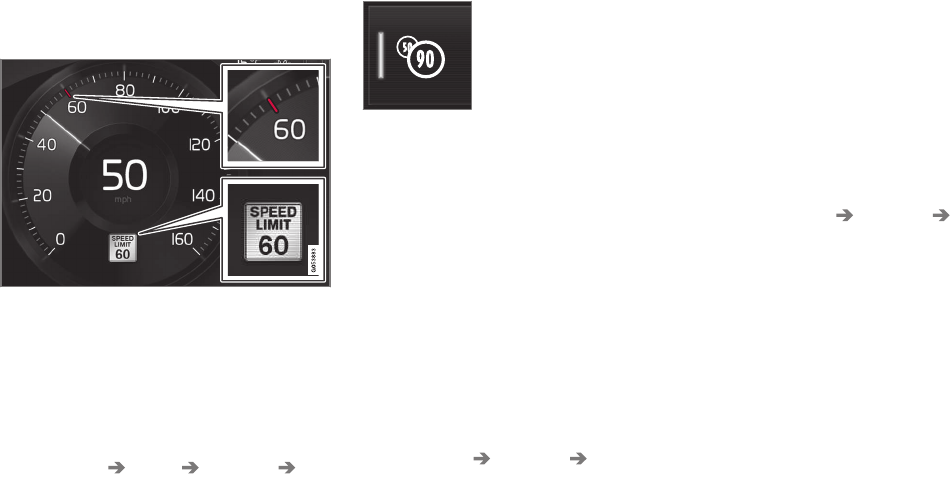
DRIVER SUPPORT
}}
* Option/accessory, for more information, see Introduction. 295
Road Sign Assistance (RSI)*
operation
Speed limit information
Speed limit information
When RSI registers a road sign showing the
speed limit, this sign is displayed as a symbol on
the instrument panel.
Settings
RSI settings can be made in the center display's
Top view.
Go to: Settings My Car IntelliSafe
Road Sign Information.
Activating/deactivating RSI
RSI can be activated/deacti-
vated in the center display's
function view.
–Tap the Road Sign Information button in
Function view.
> When RSI is activated, the indicator light
in the button will be green. The indicator
light will be gray when the function is
deactivated.
Activating/deactivating the speed warning
function
The driver can be alerted if the current speed
limit is being exceeded (the symbol for the cur-
rent speed limit will begin to flash). This function
can be activated or deactivated and the limit for a
warning can be set.
1. Tap Settings in the center display's Top
view.
2. Tap My Car IntelliSafe Road Sign
Information.
3. Tap Speed Limit Warning to activate/deac-
tivate this function.
> If the function is activated, a speed selec-
tor will be displayed.
4. Select the limit at which the speed warning is
to be given by pressing the up/down arrows.
Please be aware that the set warning limit
will not be used when a speed camera sym-
bol is displayed in the instrument panel.
Activating/deactivating the audible alert
The audible alert can be activated/deactivated
and the limit for a warning can be set.
1. Tap Settings in the center display's Top
view.
2. Tap My Car IntelliSafe Road Sign
Information.
3. Tap Audio Warning to activate/deactivate
this function.
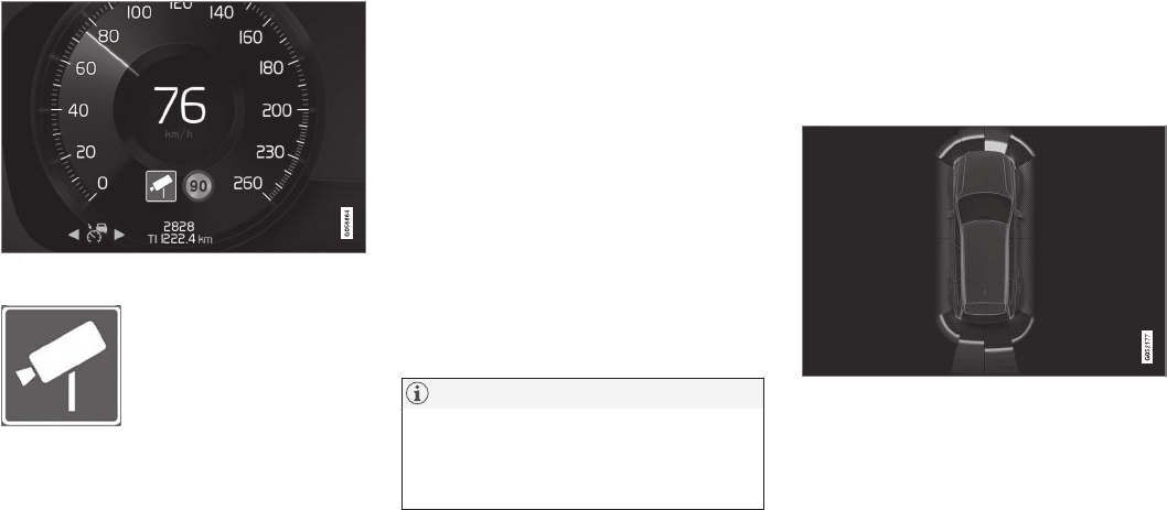
||
DRIVER SUPPORT
* Option/accessory, for more information, see Introduction.
296
Speed camera alert
Speed camera warning in the instrument panel (generic
illustration)
If the Sensus navigation system
in your vehicle is being used,
the driver can be alerted if the
vehicle is exceeding a detected
speed limit and is approaching
a speed camera.
Related information
•Road Sign Information (RSI)* (p. 294)
Road Sign Assistance (RSI)*
limitations
RSI is a feature that helps the driver see road
signs showing the posted speed limit.
RSI may have difficulty reading signs that are:
•Faded
•Located in a curve
•Twisted or damaged
•Positioned high above the road
•Obstructed (by bushes, etc.)
•Partially covered by snow, ice, etc.
The camera used by RSI (and other driver sup-
port systems such as Adaptive Cruise Control*)
has certain limitations. See the article "City
Safety limitations" for additional information.
NOTE
RSI may perceive certain types of bicycle
holders (with wiring attached to the trailer
electrical socket) as a trailer, which may result
in faulty speed limit information to the driver.
Related information
•City Safety limitations (p. 283)
•Road Sign Information (RSI)* (p. 294)
Park Assist*
The Park Assist system is designed to assist you
when driving into parking spaces, garages, etc.
An audible signal and symbols in the instrument
panel and center display indicate the distance to
the object.
Display view showing object zones and sensor sectors
The center display shows an overview of the vehi-
cle in relation to objects that have been detected.
The highlighted sector shows which of the sen-
sors has detected the object. The closer the
highlighted sector is to the vehicle symbol, the
closer the actual object is to your vehicle.
The Park Assist system uses an intermittent tone
that pulses faster as you come closer to an
object. Sound from the infotainment system will
be temporarily turned down.
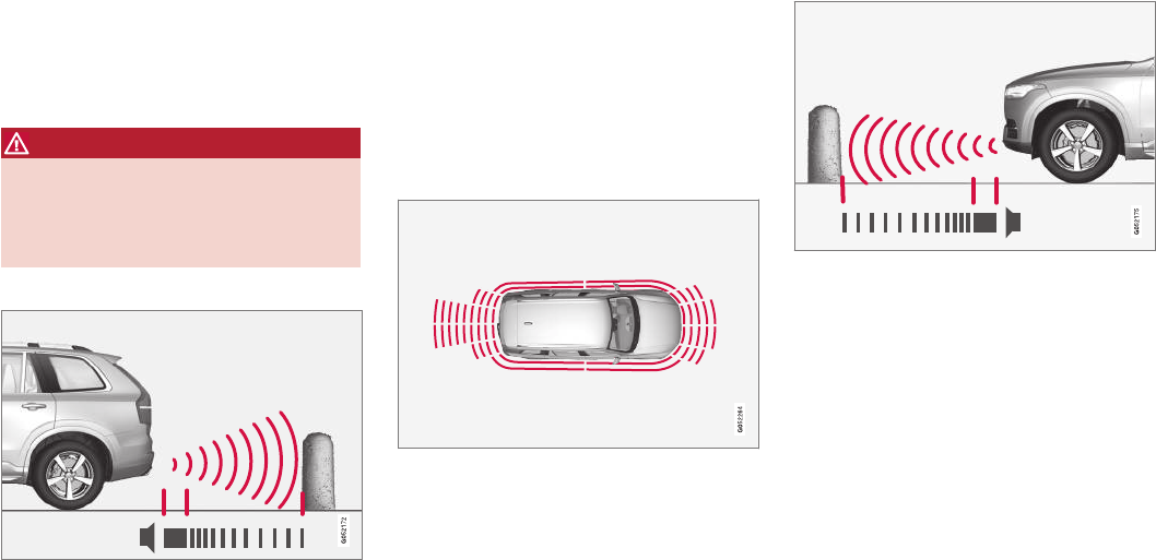
DRIVER SUPPORT
}}
297
The tone becomes constant when you are within
approximately 1 ft (30 cm) of an object and the
innermost sensor field will be red. If there are
objects within this distance both behind and in
front of the vehicle, the tone alternates between
front and rear speakers.
While an audible signal is being given, its volume
level can be raised/lowered using the >II control
in the center console or can be adjusted in the
Setting menu.
WARNING
Park Assist is an information system, NOT a
safety system. This system is designed to be
a supplementary aid when parking the vehicle.
It is not, however, intended to replace the driv-
er's attention and judgement.
Rear park assist
The system's rear sensors are activated automat-
ically when the engine is started and are active if
the vehicle rolls rearward with the gear selector
in N or if R has been selected.
The distance monitored behind the vehicle is
approximately 5 ft (1.5 m). The audible signal
comes from the rear speakers.
The rear sensors will be deactivated automatically
when towing a trailer if Volvo genuine trailer wir-
ing is used. If a non-Volvo trailer hitch is being
used, it may be necessary to switch off the sys-
tem manually.
Side park assist
The system's side sensors are activated automat-
ically when the engine is started and are active at
speeds below approximately 6 mph (10 km/h).
The distance monitored along the sides of the
vehicle is approximately 1 ft (0.3 m). The audible
signal comes from the side speakers.
Front park assist
The system's front sensors are activated auto-
matically when the engine is started and are
active at speeds below approximately 6 mph
(10 km/h).
The distance monitored in front of the vehicle is
approximately 2.5 ft (0.8 m). The audible signal
comes from the front speakers.
Front Park Assist is deactivated if the parking
brake is applied or if the gear selector is put in P.
When installing auxiliary headlights, be sure that
they do not obstruct the front sensors. Otherwise,
these lights could trigger a Park Assist warning.

||
DRIVER SUPPORT
* Option/accessory, for more information, see Introduction.
298
Related information
•Activating/deactivating Park Assist (p. 298)
•Park Assist limitations (p. 298)
•Park assist symbols and messages (p. 300)
Activating/deactivating Park Assist
The Park Assist system can be turned on or off.
On/Off
Park Assist's front and side sensors are activated
automatically when the engine is started. The
rear sensors activate if the vehicle rolls rearward
in N or if R is selected.
This function can be activated/
deactivated in the center dis-
play's Function view.
–Tap the Park Assist button.
> Green indicator: the function is active.
Gray indicator: the function is deactivated.
Related information
•Park Assist* (p. 296)
•Park Assist limitations (p. 298)
•Park assist symbols and messages (p. 300)
Park Assist limitations
The Park Assist system has certain limitations.
NOTE
A trailer hitch whose wiring is integrated with
the vehicle's electrical system will be taken
into account when measuring the available
space behind the vehicle.
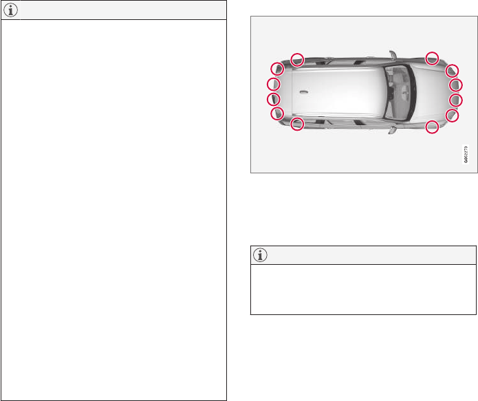
DRIVER SUPPORT
* Option/accessory, for more information, see Introduction. 299
NOTE
•The system will not detect high objects,
such as a loading dock, etc.
•Certain materials or fabrics may not be
detected by the sensors. Objects made of
these materials or people wearing cloth-
ing made of these fabrics may not be
detected.
•Children or animals near the vehicle may
not always be detected.
•Objects such as chains, thin shiny poles
or low objects may temporarily not be
detected by the system. This may result
in the pulsing tone unexpectedly stopping
instead of changing to a constant tone as
the vehicle approaches the object. In
such cases, use caution when backing up
or stop the vehicle to help avoid damage.
•In certain circumstances, the park assist
system may give unexpected warning sig-
nals that can be caused by external
sound sources that use the same ultra-
sound frequencies as the system. This
may include such things as the horns of
other vehicles, wet tires on asphalt, pneu-
matic brakes, motorcycle exhaust pipes,
other vehicles with similar ultrasound sys-
tems, etc. This does not indicate a fault in
the system.
Cleaning the sensors
Location of the Park Assist sensors
The sensors must be cleaned regularly to ensure
that they work properly. Clean them with water
and a suitable car washing detergent.
NOTE
If the sensors are obstructed by e.g., dirt,
snow, or ice, this could result in false warning
signals from the park assist system.
Related information
•Park Assist* (p. 296)
•Activating/deactivating Park Assist (p. 298)
•Park assist symbols and messages (p. 300)

DRIVER SUPPORT
300
Park assist symbols and messages
A number of messages relating to Park Assist
will appear in the instrument panel.
The following table provides some examples.
Message Explanation
Park Assist System
Unavailable Service required
The system is not functioning properly. Contact a trained and qualified Volvo service technician.
Park Assist System
Sensors blocked, cleaning needed
One or more of the system's sensors are blocked. Check and clean the sensors as soon as possible.
Related information
•Park Assist limitations (p. 298)
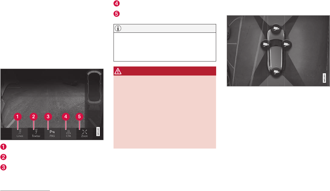
DRIVER SUPPORT
}}
* Option/accessory, for more information, see Introduction. 301
Park Assist Camera (PAC)*
The Park Assist Camera system is designed to
provide the driver with a view of the area around
the vehicle in the form of a camera image and
graphics in the center display.
PAC is a supplementary parking aid that can be
activated automatically when the gear selector is
in R or by tapping a button in the center display,
depending on the selected settings. See also the
article "Starting the Park Assist Camera."
Guiding lines On/Off
Guiding lines for a trailer hitch*2 On/Off
Park Assist On/Off
Cross Traffic Alert* On/Off
Zoom3
NOTE
A trailer hitch whose wiring is integrated with
the vehicle's electrical system will be taken
into account when measuring the available
space behind the vehicle.
WARNING
•PAC is designed to be a supplementary
aid when parking the vehicle. It is not,
however, intended to replace the driver’s
attention and judgment.
•The camera has blind spots where it can-
not detect objects or people around or
near the vehicle.
•Pay particular attention to people or ani-
mals that are close to the vehicle.
•Objects seen on the screen may be
closer than they appear to be.
Camera views
Panorama (360°) view
Location of the cameras and their fields of vision
All four sides of the vehicle are shown in the cen-
ter display to help the driver monitor objects
close-by when maneuvering at low speeds.
Each camera view can be displayed separately:
•Tap the center display in the desired "field of
vision," e.g., behind the rear camera, etc.
The camera view selected (front/left/right/rear)
will be indicated at the top of the graphic.
The cameras can be activated automatically or
manually, see the article "Park Assist Camera
settings."
2Not available in all markets.
3Only available on vehicles with a trailer hitch.
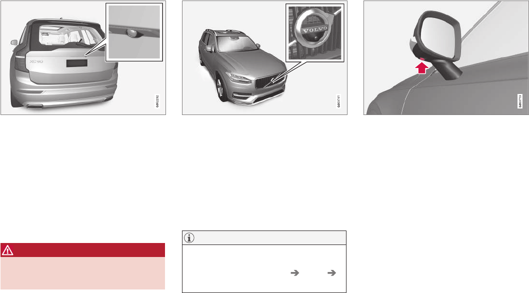
||
DRIVER SUPPORT
* Option/accessory, for more information, see Introduction.
302
Backing up
Location of the rear Park Assist Camera
The rear camera shows a wide area, part of the
bumper and the trailer hitch (if installed).
Some objects on the screen may appear to “lean”
slightly, which is normal.
If the vehicle is also equipped with the optional
Park Assist system, this information will be dis-
played on the screen as colored fields showing
the distance to obstacles that have been
detected. See also the article "Park Assist
Camera guiding lines and fields."
WARNING
People/objects/obstructions displayed on the
center console screen may be closer to the
vehicle than they appear.
Front camera
The front camera is located behind the grill and
can be useful when driving off in areas with lim-
ited visibility (hedges, bushes, etc). It is active at
speeds up to approx. 16 mph (25 km/h) and is
automatically turned off when the vehicle
exceeds this speed.
However, if the vehicle's speed remains under
31 mph (50 km/h) for 60 seconds and its speed
goes under 22 mph (22 km/h), the front camera
will reactivate.
NOTE
The front camera will only reactivate automati-
cally if Auto Camera Reverse Activation
has been selected in Settings My Car
Park Assist.
Side camera
The side cameras are located in the respective
door mirrors.
Related information
•Park Assist Camera (PAC)* trajectory lines
and fields (p. 303)
•Park Assist Camera (PAC)* limitations
(p. 306)
•Starting the Park Assist Camera (PAC)*
(p. 305)
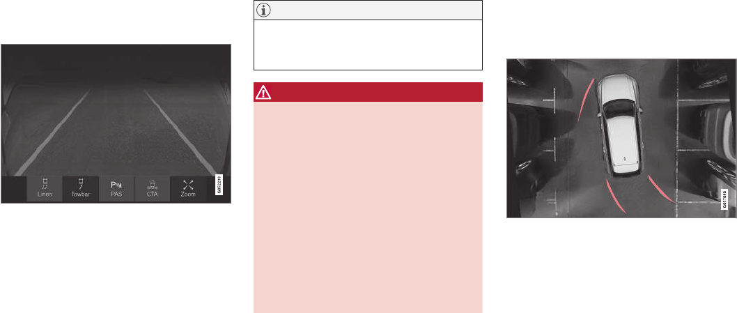
DRIVER SUPPORT
}}
* Option/accessory, for more information, see Introduction. 303
Park Assist Camera (PAC)*
trajectory lines and fields
The Park Assist Camera system uses trajectory
and lines and fields to indicate the vehicle's
position in relation to its immediate surround-
ings.
Trajectory lines
Sample guidelines
The trajectory lines are intended to show the
position of the vehicle's outermost dimensions
based on the current position of the steering
wheel to help simplify parallel parking, backing
into tight spaces or when attaching a trailer.
The lines on the screen are projected as if they
were a path on the ground around the vehicle
and are directly affected by the way in which the
steering wheel is turned. This enables the driver
to see path the vehicle will take, even if he/she
turns the steering wheel.
These lines also indicate the outermost limits that
any object (door mirrors, corners of the body, a
trailer hitch, etc.) extends out from the vehicle,
even when it turns.
NOTE
When backing up with a trailer, the trajectory
lines show the path that the vehicle will take,
not the trailer.
WARNING
Keep in mind that when the rear camera has
been selected, the image on the screen only
shows the area behind the vehicle. The driver
must always watch for people, animals, other
vehicles, etc., near the sides or the front of the
vehicle when turning while backing up.
The opposite is true when the front camera is
selected.
Please note that the trajectory lines show the
shortest path. Be sure that the vehicle’s sides
do not come into contact with or scrape
against any obstacle/obstruction when the
steering wheel is turned while driving forward
or that the front of the vehicle does not come
into contact with or scrape against any obsta-
cle/obstruction when backing up.
Models with the 360° panorama camera
system and Park Assist sensors*
On models with the 360° panorama camera sys-
tem, trajectory lines will be shown in front of or to
the sides of the vehicle, depending on its direc-
tion.
•When driving forward: front lines
•When backing up: side/rear lines
Location of the cameras and their fields of vision
With 360° view selected, the center display will
show views from all of the parking cameras.
To select a specific camera, tap its "field of
vision."
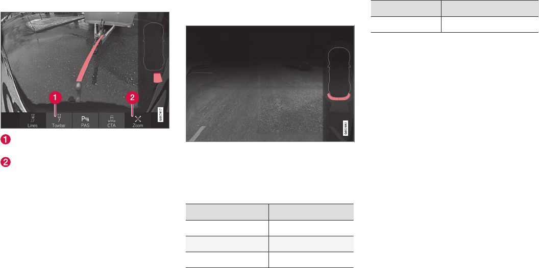
||
DRIVER SUPPORT
* Option/accessory, for more information, see Introduction.
304
Trajectory lines for a trailer hitch (towbar)
Towbar: activate trajectory lines for a trailer
hitch
Zoom: zoom in/out
The camera can help make hitching a trailer eas-
ier by showing the "line" that the trailer hitch will
take toward the trailer.
1. Tap Towbar (1).
> The trajectory lines will be displayed and
the trajectory lines for the vehicle will dis-
appear.
2. Tap Zoom (2) for a close-up view.
> The camera will zoom in.
trajectory lines for the trailer hitch and the vehicle
cannot be shown at the same time.
Front and rear sensor fields
Front and rear sensors
The screen can display colored sensor fields on the car
symbol at the right
The front and rear fields change colors (yellow-
orange-red) as the vehicle moves closer to an
object.
Front/rear field colors Distance to the object
Yellow 2–4.9 ft (06.–1.5 m )
Orange 1.3–2 ft (0.4–0.6 m)
Red 0–1.3 ft (0–0.4 m)
Side sensors
The side fields will only be shown in orange.
Side field color Distance to the object
Orange 0–1 ft (0–0.3 m)
Related information
•Park Assist Camera (PAC)* (p. 301)
•Starting the Park Assist Camera (PAC)*
(p. 305)

DRIVER SUPPORT
* Option/accessory, for more information, see Introduction. 305
Starting the Park Assist Camera
(PAC)*
PAC starts automatically when the gear selector
is moved to R or can be started manually from
the center display.
Starting the camera
PAC can be started manually in
the center display's Function
view if it is turned off.
–Tap the Camera button.
> The camera will start.
Starting the camera in different
situations
When the button is tapped, the vehicle's speed
and direction determine if the camera starts in
top view or front view:
•Top view: if the vehicle is stationary or is
moving forward at speeds up to 9 mph
(15 km/h)
•Top view: if the vehicle is stationary or is
reversing, regardless of speed
•Front view: if the vehicle is moving forward at
speeds between 9–14 mph (15–22 km/h)
Activating/deactivating automatic start
of PAC
PAC can be started automatically when reverse
gear is selected.
1. Tap Settings in the center display's Top
view.
2. Tap My Car Park Assist.
3. Select Auto Camera Reverse Activation
to activate/deactivate automatic start.
Automatically deactivating the camera
Front view switches off at a speed of approx. 16
mph (25 km/h) to help avoid distracting the
driver. If the setting Auto Camera Reverse
Activation has been selected, the camera's front
view will reactivate if the vehicle's speed drops
below 14 mph (22 km/h) within 60 seconds. If
the vehicle's speed has exceeded 31 mph (50
km/h), front view will not automatically reactivate.
Other camera views switch off at 9 mph (15
km/h) and will not reactivate automatically.
Selecting the camera's basic view when
reversing
With Auto Camera Reverse Activation
selected, the driver can also choose the camera
view to be used when reversing: the rear view or
360° view*.
1. Tap Settings in the center display's Top
view.
2. Tap My Car Park Assist.
3. Select Rear View Instead of 360° to set
the rear view as default.
Related information
•Park Assist Camera (PAC)* trajectory lines
and fields (p. 303)
•Park Assist Camera (PAC)* limitations
(p. 306)
•Ignition modes (p. 360)
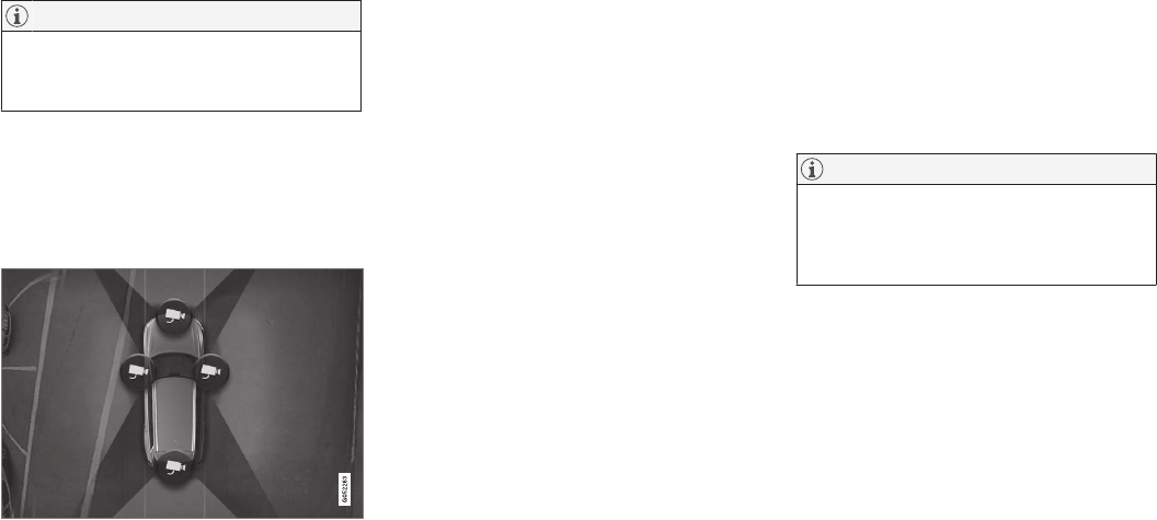
DRIVER SUPPORT
* Option/accessory, for more information, see Introduction.
306
Park Assist Camera (PAC)*
limitations
The Park Assist Camera system has certain limi-
tations that the driver should be aware of.
NOTE
Bicycle carriers or other accessories mounted
on the tailgate may obstruct the camera's
field of vision.
Blind sectors
Even if a fairly small section of the screen image
appears to be obstructed, this may mean that a
relatively large area is hidden and objects there
may not be detected until they are very near the
vehicle.
The "blind" sectors between the cameras' fields of vision
•With 360° view selected, objects/obstacles
may not be detected at the edges of the indi-
vidual cameras' fields of vision.
•A crossed-out camera icon means that the
camera is not functioning properly.
Ambient lighting
The camera images are adjusted automatically to
the ambient light, which means the image may
vary slightly in terms of light and quality. Poor
ambient lighting may reduce the quality of the
image.
Maintenance
•Keep the camera's lens free of dirt, ice and
snow. This is particularly important in poor
ambient lighting conditions.
•Remove dirt, ice and snow carefully to avoid
scratching the lenses.
•Clean the lens regularly with warm water and
a suitable car washing detergent.
Related information
•Park Assist Camera (PAC)* (p. 301)
Park Assist Pilot (PAP)*
Park Assist Pilot (PAP) helps the driver drive into
and leave parallel parking spaces.
Park Assist Pilot (PAP) provides assistance when
parking by measuring the parking space and
turning the steering wheel to guide the vehicle
into the space.
Information about the actions required by the
driver is provided in the center display in the form
of symbols, images and text.
NOTE
The driver's task is to follow the instructions,
select a gear (D or R), regulate the vehicle's
speed, apply the brakes when necessary and
stop.
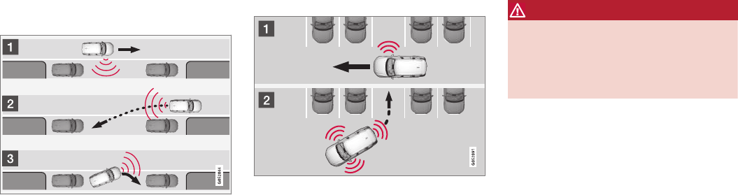
DRIVER SUPPORT
* Option/accessory, for more information, see Introduction. 307
Types of parking
Parallel parking
Procedure for parallel parking
PAP helps park the vehicle as follows:
1. The system searches for and measures a
possible parking space. While this is being
done, the vehicle's speed may not exceed
approx. 20 mph ( 30 km/h). When backing
into a space, the speed may not exceed
approx. 4 mph ( 7 km/h).
2. The vehicle is steered while it is backing into
the parking space. The driver controls the
vehicle's speed.
3. The vehicle's position in the parking space is
adjusted by prompting the driver to move for-
ward and rearward while the system steers.
Perpendicular parking
Procedure for perpendicular parking
PAP helps park the vehicle as follows:
1. The system searches for and measures a
possible parking space. While this is being
done, the vehicle's speed may not exceed
approx. 4 mph ( 7 km/h).
2. The vehicle is steered while it is backing into
the parking space and its position in the
space is adjusted by prompting the driver to
move forward and rearward while the system
steers. The driver controls the vehicle's
speed.
WARNING
•PAP does not function in all situations
and is only intended to assist the driver
during parallel or perpendicular parking.
•As the driver, you have full responsibility
for parking the vehicle in a safe manner.
Related information
•Using Park Assist Pilot (PAP)* (p. 308)
•Park Assist Pilot (PAP)* limitations (p. 310)
•Park Assist Pilot (PAP)* symbols and mes-
sages (p. 312)
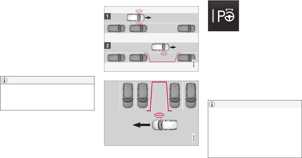
DRIVER SUPPORT
* Option/accessory, for more information, see Introduction.
308
Using Park Assist Pilot (PAP)*
Park Assist Pilot (PAP) gives the driver instruc-
tions during the parking procedure.
Symbols, images and text in the center display
indicate when the various steps in the parking
procedure will be carried out.
PAP can be activated if the following conditions
are met after the engine has started:
•The vehicle may not be towing a trailer.
•The vehicle's speed must be below approx.
30 mph (50 km/h).
NOTE
If a trailer hitch is configured in the vehicle's
electrical system, PAP will take the trailer
hitch into consideration when determining the
necessary size of a parking space.
Parking
Procedure for parking:
1. The system searches for and measures a
possible parking space.
2. The vehicle is steered while it is backing into
the parking space.
3. The vehicle's position is adjusted in the park-
ing space by moving forward and rearward.
1: Searching and measuring
Parallel parking
Perpendicular parking
PAP searches for a potential parking space and
measures it to see if there is sufficient space for
your vehicle. To start this procedure:
1. Tap the Park Assist button
in the center display's Function
view. If necessary, slow down to
a speed below 20 mph (30
km/h) for parallel parking or
approx. 12 mph ( 20 km/h) for
perpendicular parking.
2. Keep an eye on the display and be prepared
to stop the vehicle when you are instructed
by PAP to do so.
3. Select Parallel parking or Perpendicular
parking and put the transmission in reverse.
4. Keep an eye on the display and be prepared
to stop the vehicle when you are instructed
by PAP to do so.
5. Stop the vehicle when instructed to do so.
NOTE
PAP normally searches for available parking
spaces along the curb on the right (passeng-
er's) side of the vehicle. However, it can also
assist in finding and parking in spaces on the
driver's side. To do so:
•Activate the left turn signal. PAP will then
search for a parking space on the left
side of the vehicle.
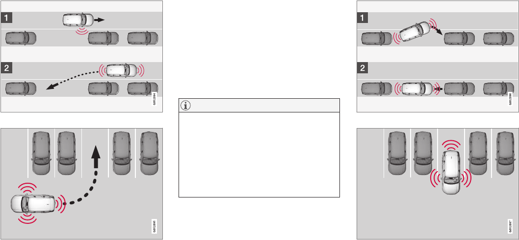
DRIVER SUPPORT
}}
309
2: Backing into the parking space
Parallel parking
Perpendicular parking
When the vehicle is backing up, PAP will steer it
into the parking space. Do as follows:
1. Check that the area behind the vehicle is
clear and put the gear selector in R.
2. Back up slowly without moving the steering
wheel. The vehicle's speed must be below
approximately 4 mph 7 km/h.
3. Keep an eye on the instrument panel and be
prepared to stop the vehicle when you are
instructed by PAP to do so.
NOTE
•Release the wheel while PAP is steering
the vehicle.
•The steering wheel must be able to turn
freely.
•For PAP to function optimally, wait until
the steering wheel is no longer turning
before beginning the next phase of the
parking procedure.
3: Adjusting the vehicle's position
Parallel
Perpendicular
After the vehicle has backed into the parking
space, its position in the space has to be
||
DRIVER SUPPORT
* Option/accessory, for more information, see Introduction.
310
adjusted by driving slightly forward and backing
up.
1. Put the gear selector in D, wait until the
steering wheel has turned and drive forward
slowly.
2. Stop the vehicle when you are instructed by
PAP to do so.
3. Put the gear selector in R, back up slowly
and stop when you are instructed by PAP to
do so.
When the parking procedure is finished (this will
be indicated by a text message and a graphic
image), PAP switches off automatically. If neces-
sary, the driver may need to make minor adjust-
ments to ensure that the vehicle is parked cor-
rectly.
CAUTION
The warning distance is shorter when PAP is
using the sensors than when Park Assist is
using them.
Leaving a parking space
This function can only be used
for a vehicle that has been par-
allel parked and is activated in
the center display's Function
view.
1. Tap the Park out button in
the center display's Function view.
2. Follow the instructions provided. The proce-
dure is the same as when parking the vehicle.
The steering wheel may turn back slightly when
the function is completed and the driver may
have to turn the back before leaving the parking
space.
If PAP determines that the driver can leave the
parking space without assistance, the function
will deactivate before the vehicle is completely
out of the space.
Related information
•Park Assist Pilot (PAP)* (p. 306)
•Park Assist Pilot (PAP)* limitations (p. 310)
•Park Assist Pilot (PAP)* symbols and mes-
sages (p. 312)
Park Assist Pilot (PAP)* limitations
The PAP function may be limited in certain situa-
tions.
The PAP parking sequence is cancelled
A parking sequence will be cancelled:
•if the vehicle is driven too fast (above approx.
4 mph (7 km/h)
•if the driver taps Cancel in the center display
•if the driver moves the steering wheel with
sufficient force.
•if the anti-lock brakes or Electronic Stability
Control are activated (e.g., if a wheel begins
to spin or lose traction)
In such cases, a text message will explain why
the parking sequence was cancelled.
NOTE
•PAP will not function correctly if its sen-
sors are obstructed by dirt, snow, etc.
•In certain situations, PAP may not be able
to measure a parking space. This could
be due to external sources of sound (e.g.,
a vehicle's horn, tires on wet asphalt,
pneumatic brakes, noise from a motorcy-
cle's exhaust, etc.) emitting ultrasound
using approximately the same frequen-
cies as PAP.
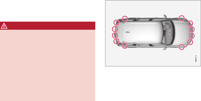
DRIVER SUPPORT
* Option/accessory, for more information, see Introduction. 311
Points to keep in mind
PAP is a parking aid only and the driver should
always be prepared to take control and cancel a
parking sequence. This can be due to one or
more of the following factors:
•PAP's function is based on the way that the
vehicles are parked behind and in front of
your parking space. If they are, for example,
parked too close to the curb, there is a risk
that your vehicle's tires or wheel rims could
be damaged by the curb during the parking
procedure.
•PAP is intended to provide parking assis-
tance on straight streets, not sections of
street with curved or irregular curbs. Be sure
that your vehicle is parallel to the curb when
PAP measures the parking space.
•PAP may not be able to provide parking
assistance on narrow streets due to lack of
space to maneuver the vehicle. In situations
like this, it may help to drive between 1.5-5 ft
(0.5-1.5 m) from the side of the road where
the parking space is located.
•Use only approved tires with the correct infla-
tion pressure because this affects PAP's
capacity to provide parking assistance.
Changing to a different approved tire size
may affect PAP's parameters. Consult a
trained and qualified Volvo service technician.
•Heavy rain or snow may inhibit PAP's
capacity to correctly measure a parking
space.
•Do not use PAP when using snow chains
and/or a temporary spare tire.
•Do not use PAP if there are any objects pro-
truding from the vehicle.
WARNING
•The front end of your vehicle may turn out
toward oncoming traffic during the park-
ing procedure.
•Objects located above the parking sen-
sors' field of vision are not included when
PAP measures a parking space. For this
reason, PAP may turn into the parking
space too soon. Avoid parking spaces of
this type.
•The driver is always responsible for deter-
mining if PAP has selected a suitable
parking space.
Maintenance
Location of the PAP sensors
PAP uses the same sensors as the Park Assist
system. To function correctly, these sensors must
be cleaned regularly with water and a suitable car
washing detergent.
Related information
•Park Assist Pilot (PAP)* (p. 306)
•Park Assist Pilot (PAP)* limitations (p. 310)
•Park Assist Pilot (PAP)* symbols and mes-
sages (p. 312)

DRIVER SUPPORT
* Option/accessory, for more information, see Introduction.
312
Park Assist Pilot (PAP)* symbols
and messages
Park Assist Pilot uses graphics and text mes-
sages to indicate if there is a problem with the
system.
Various PAP-related combinations of graphics
and text messages are displayed in the instru-
ment panel and sometimes also include suitable
actions.
The following table provides some examples.
Message Explanation
Park Assist System
Unavailable Service required
The system is not functioning properly. Contact a trained and qualified Volvo service technician.
Park Assist System
Sensors blocked, cleaning needed
One or more of the system's sensors are blocked. Check and clean the sensors as soon as possible.
A text message can be erased by briefly pressing
the O button in the center of the right-side steer-
ing wheel keypad.
Contact a Volvo retailer or a trained and qualified
Volvo service technician If a message indicating
that PAP is not functioning properly remains dis-
played or recurs.
Related information
•Park Assist Pilot (PAP)* (p. 306)
•Using Park Assist Pilot (PAP)* (p. 308)
•Park Assist Pilot (PAP)* limitations (p. 310)
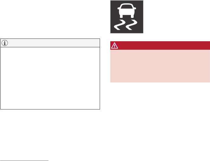
DRIVER SUPPORT
}}
* Option/accessory, for more information, see Introduction. 313
Adjustable steering force*
Steering force increases with the speed of the
vehicle to give the driver an enhanced sense of
control and stability. At low speed the vehicle is
easier to steer in order to facilitate parking, etc.
Changing the steering force level
To change the level of steering force, see the
information under the heading "individual" in arti-
cle "Drive modes" for additional information.
NOTE
•This steering force level menu function
cannot be accessed when the vehicle is
in motion.
•In certain situations, the power steering
function may become too hot and must
be temporarily cooled. During cooling,
power steering effect will be reduced and
more force may be necessary to turn the
steering wheel and a message will be
displayed in the instrument panel.
Related information
•Driver support systems (p. 242)
•Drive modes* (p. 365)
Electronic Stability Control (ESC)
Electronic Stability Control (ESC) helps reduce
wheel spin, counteract skidding and to generally
help improve directional stability.
A pulsating sound will be audi-
ble when the system is actively
operating and is normal. Accel-
eration may also be slightly
slower than normal.
WARNING
ESC is a supplementary aid and cannot deal
with all situations or road conditions.
The driver is always responsible for operating
the vehicle in a safe manner in accordance
with current traffic regulations.
ESC consists of the following functions:
•Traction control
•Spin control
•Active Yaw Control
•Engine Drag Control
•Trailer Stability Assist
Traction control
This function is designed to help reduce wheel
spin by transferring power from a drive wheel that
begins to lose traction to the wheel on the oppo-
site side of the vehicle (on the same axle).
Spin control
This function is designed to help prevent the
drive wheels from spinning while the vehicle is
accelerating.
Active Yaw Control
At low speeds, this function helps maintain direc-
tional stability by braking one or more of the
wheels if the vehicle shows a tendency to skid or
slide laterally.
Engine Drag Control EDC
EDC helps keep the engine running if the wheels
show a tendency to lock, e.g., when shifting down
in the manual shifting mode or while using the
engine's braking function on a slippery surface. If
the wheels were to lock, the vehicle would
become more difficult to steer.
Trailer Stability Assist*4
TSA helps stabilize a vehicle that is towing a
trailer when the vehicle and trailer have begun to
sway.
This system is automatically deactivated if the
driver selects Sport mode.
Related information
•Detachable trailer hitch (p. 358)
•Driving with a trailer (p. 357)
4This function is included if the vehicle is equipped with a Volvo original trailer hitch.

DRIVER SUPPORT
314
•Trailer Stability Assist (TSA) (p. 359)
•Electronic Stability Control (ESC) sport mode
(p. 314)
•Electronic Stability Control (ESC) symbols
and messages (p. 315)
Electronic Stability Control (ESC)
sport mode
ESC is always activated and cannot be switched
off.
However, the driver can select Sport mode,
which offers more active driving characteristics.
In Sport mode, the engine management system
monitors movement of the accelerator pedal and
steering wheel for sportier driving and allows
more lateral movement of the rear wheels before
ESC is triggered.
Under certain circumstances, such as when driv-
ing with snow chains, or driving in deep snow or
loose sand, it may be advisable to temporarily use
Sport mode for maximum tractive force.
If the driver releases pressure on the accelerator
pedal, ETC will also activate to help stabilize the
vehicle.
Activating/deactivating Sport mode
In the center display's Function
view, tap ESC Sport Mode.
The green indicator light in the
button will illuminate to show
that the function has been acti-
vated or gray when the function
is deactivated.
When Sport mode is activated, this
symbol will illuminate in the instrument
panel. It will remain on until the driver
deactivates the function. ETC will also
return to normal mode when the engine is restar-
ted.
Related information
•Electronic Stability Control (ESC) (p. 313)
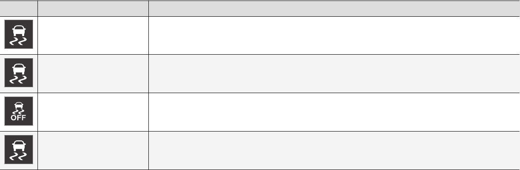
DRIVER SUPPORT
}}
315
Electronic Stability Control (ESC)
symbols and messages
Electronic Stability Control (ESC) helps reduce
wheel spin, counteract skidding and to generally
help improve directional stability.
Symbol Message Description
Steady glow for 2 seconds
when the engine is started.
The system is performing a self-diagnostic test.
Flashing symbol. ESC is actively functioning to help counteract wheel spin and/or a skid.
Steady glow. Sport mode has been activated.
Please note that ESC is not deactivated at this time but its functionality is reduced.
ESC
Temporarily off
See the message in the instrument panel.
||
DRIVER SUPPORT
316
Symbol Message Description
ESC Temporarily off The ESC system function has been temporarily reduced due to high brake disc temperature. The function reac-
tivates automatically when the brakes have cooled.
ESC Service required The ESC system is not functioning properly.
•Stop the vehicle in a safe place, turn off the engine and restart it.
•If the message is still displayed when the engine has restarted, drive to an authorized Volvo workshop to
have the system inspected.
WARNING
The stability system is intended to help
improve driving safety. It supplements, but can
never replace, the driver's judgment and
responsibility when operating the vehicle.
Speed and driving style should always be
adapted to traffic and road conditions.
Related information
•Electronic Stability Control (ESC) (p. 313)
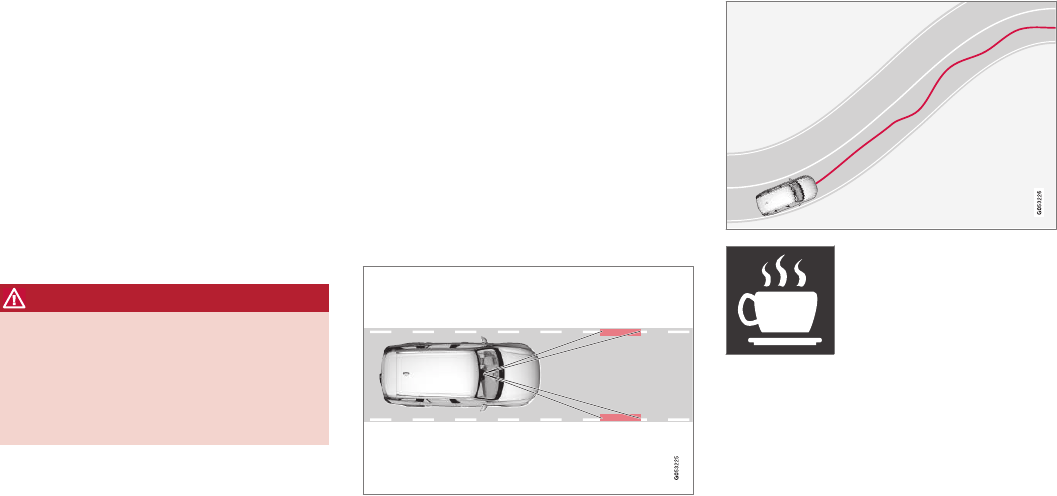
DRIVER SUPPORT
}}
317
Roll stability control (RSC)
Volvo's Roll Stability Control (RSC) is a stability
system designed to help minimize the risk of a
rollover in emergency maneuvers or if a skid
should occur.
RSC uses a gyroscopic sensor that registers the
amount of change in the lateral angle at which
the vehicle is leaning. Using this information, RSC
calculates the likelihood of a rollover. If there is
an imminent risk of a rollover, the stability system
is activated, power to the engine is cut and the
brakes are applied to one or more of the wheels
until the vehicle regains stability.
WARNING
The vehicle’s stability systems, including RSC,
do not replace the driver’s responsibility for
operating the vehicle in a safe manner. Speed
and driving style should always be adapted to
the current road, traffic and weather condi-
tions. Posted speed limits should always be
respected.
Related information
•Electronic Stability Control (ESC) (p. 313)
•General safety information (p. 56)
Driver Alert Control (DAC)
DAC is intended to alert the driver if his/her driv-
ing becomes erratic due to e.g., distraction or
fatigue.
DAC is designed to help detect a slowly chang-
ing driving pattern. It is primarily intended to be
used on main roads and is not meant for use in
city traffic.
The function activates initially when the vehicle's
speed first exceeds 40 mph (65 km/h) and
remains active as long the speed remains above
approx. 38 mph (60 km/h)
A camera monitors the traffic lane's side marker
lines and compares the direction of the road with
the driver’s movements of the steering wheel.
If the driving pattern becomes
noticeably erratic, the driver will
be alerted by an audible signal
and Driver Alert Time for a
break will appear in the instru-
ment panel along with a sym-
bol.
The warning will be repeated if the driving pattern
does not change.

||
DRIVER SUPPORT
* Option/accessory, for more information, see Introduction.
318
WARNING
•DAC is not intended to extend the dura-
tion of driving. Always plan breaks at reg-
ular intervals to help remain alert.
•A warning from DAC should not be
ignored. A driver may not be aware of
how fatigued he/she has become.
•In certain cases, fatigue may not affect
the driver’s behavior. In situations of this
type, no warning will be provided. There-
fore, it is important to take breaks at reg-
ular intervals, regardless of whether or
not DAC has given a warning.
Related information
•Using Driver Alert Control (DAC) (p. 318)
•Driver Alert Control limitations (p. 318)
Driver Alert Control limitations
The camera used by DAC (and other driver sup-
port systems such as Adaptive Cruise Control*)
has certain limitations.
In certain situations, DAC may provide warnings
even if the driver’s driving pattern has not
become erratic:
•in strong crosswinds
•on grooved road surfaces
Related information
•Driver Alert Control (DAC) (p. 317)
•Using Driver Alert Control (DAC) (p. 318)
•Driver Alert Control limitations (p. 318)
•Camera limitations (p. 244)
Using Driver Alert Control (DAC)
DAC settings are made in the center display's
menu system.
Activating/deactivating Driver Alert
Control
1. Tap Settings in the center display's Top
view.
2. Tap My Car IntelliSafe Driver Alert
Control.
3. Select Alertness Warning to activate/deac-
tivate DAC.
Activating/deactivating guidance to a
rest area
With this feature activated, DAC will propose a
nearby rest area if a warning has been given.
1. Tap Settings in the center display's Top
view.
2. Tap My Car IntelliSafe Driver Alert
Control.
3. Select Rest Stop Guidance to activate/
deactivate guidance to a rest area.
Related information
•Driver Alert Control (DAC) (p. 317)
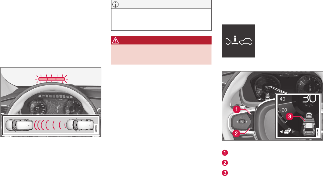
DRIVER SUPPORT
}}
* Option/accessory, for more information, see Introduction. 319
Distance Alert*
Distance Alert is a function that alerts the driver
if the time interval to the vehicle ahead is too
short.
Distance Alert is active at speeds above approxi-
mately 18 mph (30 km/h) and only reacts to a
vehicle ahead that is driving in the same direc-
tion. No information is provided for vehicles driv-
ing toward you, moving very slowly, or at a stand-
still.
Warning light
An warning light in the windshield glows steadily
if your vehicle is closer to the one ahead than the
set time interval.
If your vehicle is equipped with the optional head-
up display, a symbol will appear.
NOTE
Distance Alert only monitors distance to the
vehicle ahead while Adaptive Cruise Control is
in standby mode or off.
WARNING
Distance Alert only indicates the distance to
the vehicle ahead. It does not affect the
speed of your vehicle.
Related information
•Distance Alert* limitations (p. 320)
•Using Distance Alert* (p. 319)
Using Distance Alert*
Distance Alert is used as follows:
Operation
Pull down the center display's
Top view and select Settings
followed by Distance alert.
Tap to turn the function On or
Off.
Setting a time interval
Controls for setting a time interval
Reduce the time interval
Increase the time interval
Distance/time indicator
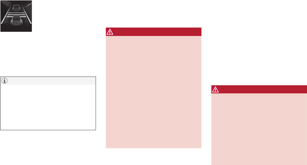
||
DRIVER SUPPORT
* Option/accessory, for more information, see Introduction.
320
Different time intervals to the
vehicle ahead can be selected
and are shown in the instru-
ment panel as 1–5 horizontal
bars. The greater the number of
bars, the longer the time inter-
val.
One bar between the vehicles represents a time
interval of approximately 1 second; 5 bars is
approximately 3 seconds.
The same symbol appears if Adaptive Cruise
Control is activated.
NOTE
•The greater the vehicles' speed, the
greater the distance between them for a
set time interval.
•The set time interval is also used by
Adaptive Cruise Control*.
•Only use time intervals permitted by local
traffic regulations.
Related information
•Distance Alert* (p. 319)
Distance Alert* limitations
Distance Alert uses the same radar sensor as
Adaptive Cruise Control* and has several limita-
tions.
WARNING
•The radar sensor has a limited field of
vision. In some situations it may detect a
vehicle later than expected or not detect
other vehicles at all.
•The radar sensor cannot cover all driving
situations and traffic, weather and road
conditions.
•The driver is responsible for maintaining a
safe distance and speed and must inter-
vene if the various driver support systems
do not maintain a suitable speed or suita-
ble distance to the vehicle ahead.
•Maintenance of radar sensor components
may only be performed by a trained and
qualified Volvo technician.
•Strong sunlight, reflections from the road
surface, strong lighting contrasts or using
sunglasses may make the warning light in
the windshield difficult to see.
For additional information, see also the article
"Radar sensor limitations."
Related information
•Radar sensor limitations (p. 248)
•Distance Alert* (p. 319)
Blind Spot Information (BLIS)*
Blind Spot Information is a system designed to
alert the driver to the presence of other vehicles
moving in the same direction as your vehicle on
roads with several lanes.
Blind Spot Information is a driving aid intended
to:
•detect other vehicles in your door mirrors'
"blind area"
•detect vehicles that are about to pass your
vehicle or are approaching your vehicle
quickly from behind in the left and/or right
lanes
WARNING
•Blind Spot Information is an information
system, NOT a warning or safety system
and does not function in all situations.
•Blind Spot Information does not eliminate
the need for you to visually confirm the
conditions around you, and the need for
you to turn your head and shoulders to
make sure that you can safely change
lanes or back up.
•As the driver, you have full responsibility
for changing lanes/backing up in a safe
manner.
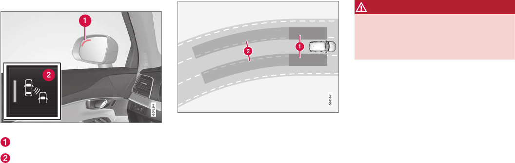
DRIVER SUPPORT
* Option/accessory, for more information, see Introduction. 321
Overview
Blind Spot Information indicators
Indicator light
Blind Spot Information symbol
The indicator light illuminates on the side of the
vehicle where the system has detected another
vehicle. If your vehicle is passed on both sides at
the same time, both lights will illuminate.
Principle for Blind Spot Information: Zone 1. Blind area,
Zone 2. Area for approaching/passing vehicles
Blind Spot Information functions when your vehi-
cle is moving at speeds above approx. 6 mph
(10 km/h).
Blind Spot Information is designed to react to:
•vehicles that are passing your vehicle
•other vehicles that are rapidly approaching
your vehicle
When Blind Spot Information detects a vehicle in
zone 1 or a fast-approaching vehicle in zone 2,
the indicator light in the respective door mirror
will glow steadily.
If the driver then uses the turn signal on the side
on which the warning is given, the indicator light
will begin flashing and become brighter.
WARNING
•Blind Spot Information does not function
in sharp curves.
•Blind Spot Information does not function
when your vehicle is backing up.
Related information
•Blind Spot Information (BLIS)* On/Off
(p. 322)
•Blind Spot Information (BLIS)* limitations
(p. 322)
•Cross Traffic Alert (CTA)* (p. 323)
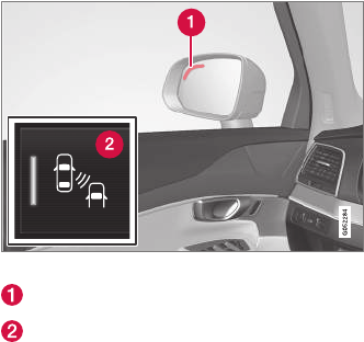
DRIVER SUPPORT
* Option/accessory, for more information, see Introduction.
322
Blind Spot Information (BLIS)*
On/Off
The Blind Spot Information function can be acti-
vated/deactivated.
Blind Spot Information indicators
Indicator light
Blind Spot Information symbol
Blind Spot Information can be activated/deacti-
vated in the center display's Function view.
–In Function view, tap BLIS.
> When Blind Spot Information is activated/
deactivated, the indicator light in the but-
ton will be green/gray.
If BLIS is activated when the engine is started,
the indicator lights in the door mirrors will flash
once.
If BLIS is deactivated when the engine is
switched off, it will remain off the next time the
engine is started and the indicator lights in the
door mirrors will not illuminate.
Related information
•Blind Spot Information (BLIS)* (p. 320)
Blind Spot Information (BLIS)*
limitations
Blind Spot Information functionality may be
reduced in certain situations.
•Dirt, ice and snow on the sensors may
reduce functionality and prevent the system
from providing warnings.
•Do not attach any objects, tape, decals, etc.,
on the surface of the sensors.
•BLIS is deactivated if a trailer is attached to
the vehicle's electrical system.
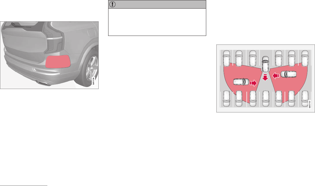
DRIVER SUPPORT
}}
* Option/accessory, for more information, see Introduction. 323
Maintenance
The BLIS/CTA5 sensors are located on the
inside of the rear fenders/bumper.
Keep the highlighted area clean (on both sides of the
vehicle)
For the system to function optimally, the area
over and around the sensors must be kept clean.
If one or both of the sensors are blocked and
"Rear sensors blocked, cleaning needed" is
displayed in the instrument panel, clean the area
over and around the sensors as soon as possible.
A text message can be erased by briefly pressing
the O button on the right-side steering wheel
keypad.
CAUTION
Repairs to the BLIS/CTA systems and/or
repainting the rear bumper should only be
done by a trained and qualified Volvo service
technician.
Related information
•Blind Spot Information (BLIS)* On/Off
(p. 322)
•Blind Spot Information (BLIS)* (p. 320)
•Cross Traffic Alert (CTA)* (p. 323)
Cross Traffic Alert (CTA)*
Cross Traffic Alert (CTA) is a supplementary part
of Blind Spot Information and is intended to
detect vehicles crossing behind your vehicle
while you are backing up.
When does Cross Traffic Alert function
Principle for CTA
CTA supplements BLIS by warning the driver of
crossing traffic behind your vehicle, for example,
when backing out of a parking space.
It is primarily designed to detect another vehicle
but in certain cases may also detect pedestrians
or smaller objects such as bicycles.
CTA is only activated when the vehicle is rolling
rearward or backing up and is activated automati-
cally when the gear selector is put in reverse.
5Cross Traffic Alert*
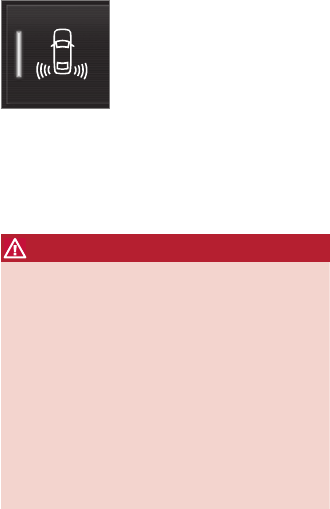
||
DRIVER SUPPORT
* Option/accessory, for more information, see Introduction.
324
•An audible signal indicates that CTA has
detected something that is approaching from
the side. The signal will come from either the
left or right infotainment system speakers,
depending on which the side of your vehicle
the approaching vehicle/ object has been
detected.
•A warning is indicated using the Park Assist*
system's graphic in the instrument panel.
•An icon is also shown in the Park Assist
Camera's* Top view.
Related information
•Activating/deactivating Cross Traffic Alert
(CTA)* (p. 324)
•Blind Spot Information (BLIS)* with Cross
Traffic Alert (CTA)* symbols and messages
(p. 327)
•Cross Traffic Alert (CTA)* limitations (p. 325)
Activating/deactivating Cross Traffic
Alert (CTA)*
Cross Traffic Alert (CTA) can be activated/deac-
tivated separately from Blind Spot Information
(BLIS).
CTA is activated/deactivated in
the center display's Function
view.
–Tap Cross Traffic Alert in Function view.
> CTA activates/deactivates (the indicator
light in the button will be green/gray).
CTA is activated when the engine is started.
WARNING
•BLIS and CTA are information systems,
NOT warning or safety systems and do
not function in all situations.
•BLIS and CTA do not eliminate the need
for you to visually confirm the conditions
around you, and the need for you to turn
your head and shoulders to make sure
that you can safely change lanes or back
up.
•As the driver, you have full responsibility
for changing lanes/backing up in a safe
manner.
Related information
•Cross Traffic Alert (CTA)* (p. 323)
•Blind Spot Information (BLIS)* On/Off
(p. 322)
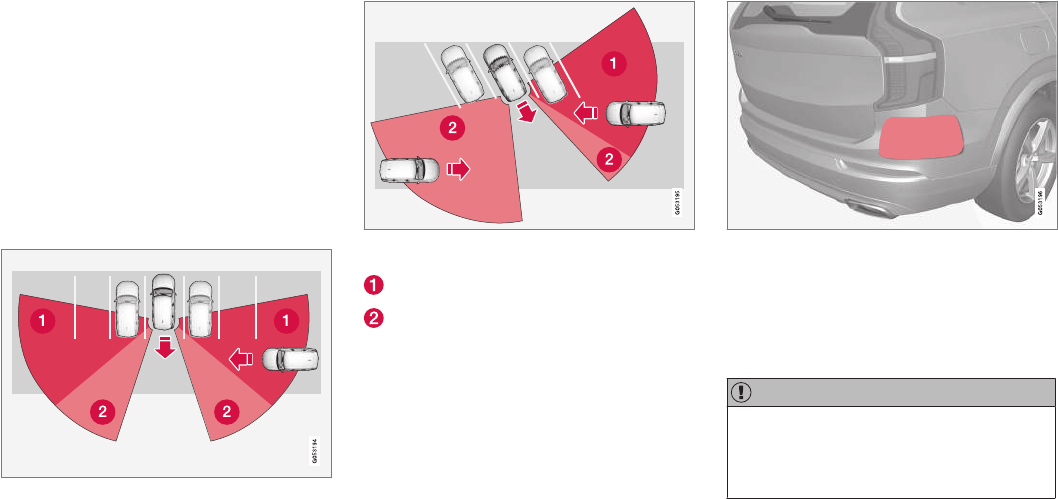
DRIVER SUPPORT
}}
* Option/accessory, for more information, see Introduction. 325
Cross Traffic Alert (CTA)* limitations
CTA functionality may be reduced in certain sit-
uations.
Limitations
CTA has limitations in certain situations, for
example, the CTA sensors cannot "see" through
other parked vehicles or obstructions.
The following are several examples where CTA's
"field of vision" may initially be limited and
approaching vehicles cannot be detected until
they are too close:
The vehicle is pulled far into a parking space
In angled parking spaces, CTA may be "blind" on one
side
CTA's blind area
CTA's "field of vision"
However, as you back your vehicle out of a park-
ing space, CTA's "field of vision" expands.
Examples of other limitations include:
•Dirt, ice or snow obstructing the sensors may
reduce the system's function or make it
impossible to detect other vehicles or
objects.
•CTA is deactivated if a trailer's wiring is con-
nected to the vehicle's electrical system.
Maintenance
The CTA sensors are located on the inside of the
rear fenders/bumper.
Keep the highlighted area clean (on both sides of the
vehicle)
For the system to function optimally, the area
over and around the sensors must be kept clean.
Do not attach any objects, tape, decals, etc., on
the surface of the sensors.
CAUTION
Repairs to the BLIS/CTA systems and/or
repainting the rear bumper should only be
done by a trained and qualified Volvo service
technician.
Related information
•Cross Traffic Alert (CTA)* (p. 323)
•Activating/deactivating Cross Traffic Alert
(CTA)* (p. 324)

DRIVER SUPPORT
* Option/accessory, for more information, see Introduction. 327
Blind Spot Information (BLIS)* with
Cross Traffic Alert (CTA)* symbols
and messages
In situations where Blind Spot Information
and/or Cross Traffic Alert are not functioning
properly or if the function is interrupted, a sym-
bol and a text message may be displayed in the
instrument panel. Follow the instructions provi-
ded.
Symbol Message Explanation
Blind spot sensor
Service required
The system is not functioning properly. Contact a trained and qualified Volvo service technician
Blind spot sensor
Rear sensors blocked, cleaning needed
One or more of the system's sensors are blocked. Check and clean the sensors as soon as possi-
ble.
Blind spot system off
Trailer attached
BLIS and CTA have been deactivated because a trailer has been connected to teh vehicle's electri-
cal system.
Related information
•Cross Traffic Alert (CTA)* (p. 323)
•Blind Spot Information (BLIS)* (p. 320)
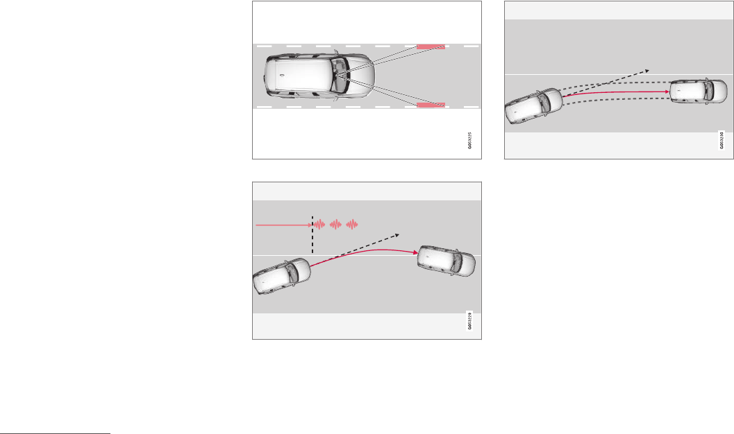
DRIVER SUPPORT
* Option/accessory, for more information, see Introduction.
328
Driving lane assistance
The Lane Departure Warning (LDW) and Lane
Keeping Aid (LKA)* functions are designed to
help reduce the risk of accidents in situations
where the vehicle unintentionally leaves its lane
on highways or other major roads.
Driving lane assistance systems: LDW
or LKA
There are two versions of the driving lane assis-
tance system:
•LDW (Lane Departure Warning): provides
an audible signal or vibrations in the steering
wheel.
•LKA (Lane Keeping Aid): actively steers the
vehicle to help keep it in its traffic lane
and/or alerts the driver using an audible sig-
nal or through vibrations in the steering
wheel.
The driving lane assistance systems are active at
speeds from approx. 40 mph (65 km/h) up to the
vehicle's permitted top speed on roads with
clearly visible traffic lane marker lines.
On narrow roads, the systems may not function
and will go into standby mode. They will return to
active mode if the road becomes sufficiently
wide.
A camera monitors the road/traffic lane's marker lines
Both LDW and LKA provide vibrations in the steering
wheel6
LKA attempts to steer the vehicle back into its lane
Depending on the version and settings used,
driving lane assistance functions in different
ways:
•If the system is activated (either LDW or
LKA): if the driver does not react and the
vehicle is moving out of its traffic lane, an
audible signal and/or vibrations in the steer-
ing wheel will be provided.
•If the system is activated (LKA only): when
the vehicle approaches a traffic lane marker
line, LKA will provide active steering assis-
tance to help steer it back into the lane.
6The level of vibrations varies; the longer the vehicle is over a lane marker line, the greater the number of vibrations:
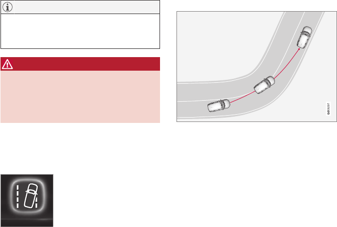
DRIVER SUPPORT
* Option/accessory, for more information, see Introduction. 329
NOTE
If the turn signal is used, neither of the driving
lane assistance systems (LDW or LKA) will
provide an alert or steering assistance.
WARNING
This feature is only intended to assist the
driver and does not function in all driving,
weather, traffic or road conditions.
As the driver, you have full responsibility for
operating the vehicle in a safe manner.
Steering assistance (LKA only)
In order for LKA's steering assistance to function,
the driver's hands must be on the steering wheel,
which the system monitors continuously.
If this is not the case, this sym-
bol will illuminate in the instru-
ment panel and Lane Keeping
Aid Apply steering will appear
to alert the driver to actively
steer the vehicle.
If the driver does not take action, an audible sig-
nal will sound and LKA will go into standby mode.
The function will not become available again until
the driver actively steers the vehicle.
Dynamic cornering
The traffic lane assistance systems do not intervene in
sharp curves
In certain cases, such as during active driving or if
the turn signal is used, neither of the traffic lane
systems will react if the vehicle crosses a lane
marker line.
Limitations
In certain demanding driving situations, the driv-
ing lane assistance functions may not be able to
assist the driver. In these situations, it may be
advisable to turn the function off.
Examples of these situations:
•road construction
•poor road surfaces
•edges or lines other than the lane's marker
lines
•a very active driving style
•winter driving conditions
•bad weather with reduced visibility
The driving lane assistance function use the vehi-
cle's camera, which has general limitations. See
the article "Camera limitations."
Related information
•Activating/deactivating Lane Departure
Warning (LDW) (p. 330)
•Activating/deactivating Lane Keeping Aid
(LKA)* (p. 330)
•Camera limitations (p. 244)
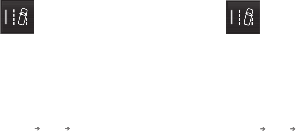
DRIVER SUPPORT
* Option/accessory, for more information, see Introduction.
330
Activating/deactivating Lane
Departure Warning (LDW)
LDW can be activated/deactivated.
Activating/deactivating
The function can be activated/deactivated in the
center display's Function view.
–Tap the Lane Departure Warning button.
> LDW is activated (GREEN indicator light
in the button), or is deactivated (GRAY
indicator light in the button).
Type of warning
Choose the type of warning that the driver will
receive if the vehicle starts to leave its driving
lane.
1. Tap Settings in the center display's Top
view.
2. Tap My Car IntelliSafe Lane
Departure Warning.
3. Under Lane Departure Warning feedback,
select:
•Sound: an audible warning signal will be
provided
•Vibrations: the driver will be warned by
vibrations in the steering wheel
Related information
•Driving lane assistance (p. 328)
Activating/deactivating Lane
Keeping Aid (LKA)*
LKA can be activated/deactivated.
Activating/deactivating
The function can be activated/deactivated in the
center display's Function view.
–Tap Lane Keeping Aid.
> LKA is activated (GREEN indicator light in
the button), or is deactivated (GRAY indi-
cator light in the button).
Type of warning
Choose the type of warning that the driver will
receive if the vehicle starts to leave its driving
lane.
1. Tap Settings in the center display's Top
view.
2. Tap My Car IntelliSafe Lane Keeping
Aid.

DRIVER SUPPORT
331
3. Under Lane Keeping Aid Warning
Feedback, select:
•Sound: an audible warning signal will be
provided
•Vibrations: the driver will be warned by
vibrations in the steering wheel
Type of assistance
Select the type of assistance LKA should provide:
1. Tap Settings in the center display's Top
view.
2. Tap My Car IntelliSafe Lane Keeping
Aid.
3. Under Lane Keeping Aid Assistance
Mode, select:
•Steering: the system will provide steering
assistance but no warning.
•Both: the system will provide steering
assistance and warning
•Warning: the system will provide warning
but no steering assistance
Related information
•Driving lane assistance (p. 328)
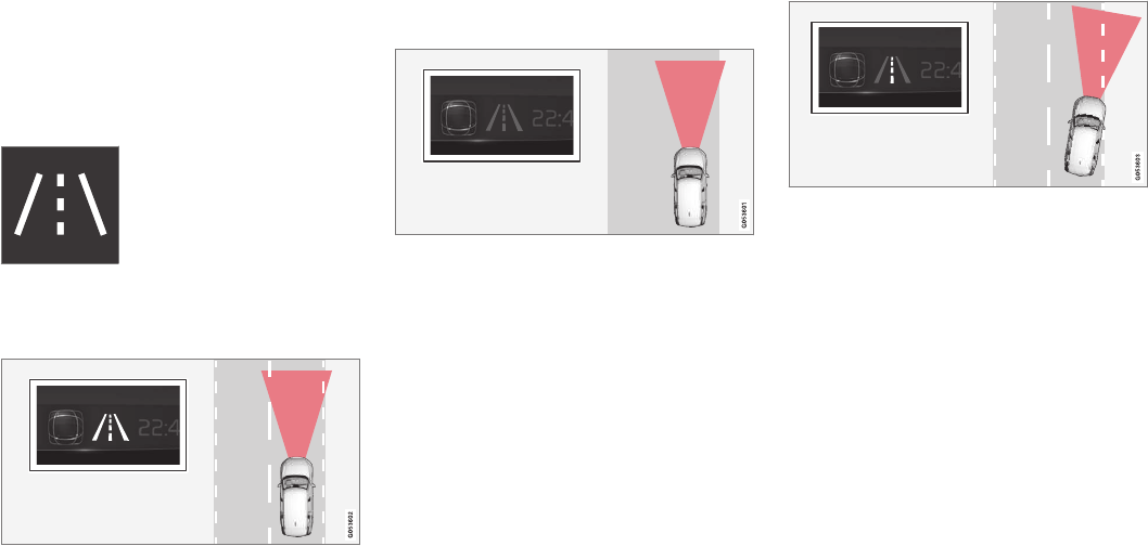
DRIVER SUPPORT
332
Driving lane assistance symbols
and messages
A number of symbols and messages relating to
Lane Keeping Aid (LKA) and Lane Departure
Warning (LDW) may appear in the instrument
panel.
Symbols in the instrument panel
The driving lane assistance
systems use a symbol in the
instrument panel in different
situations.
Several examples of the symbol's appearance will
be given here:
Available
When the driving lane assistance systems are available,
the marker lines in the symbol will be white
LDW/LKA are monitoring the driving lane's
marker line(s).
Not available
When the driving lane assistance systems are not avail-
able, the marker lines in the symbol will be gray
This is because LDW/LKA cannot monitor
(detect) the driving lane's marker line(s) or the
vehicle's speed is too low or the road is too nar-
row.
Steering/warning indicator
Steering/warning: the side marker lines in the symbol
will be colored
LDW/LKA alerts the driver that the vehicle is
leaving its lane. LKA attempts to steer the vehicle
back into the lane. LKA also indicates if the sys-
tem is attempting to steer the vehicle back into
its lane.
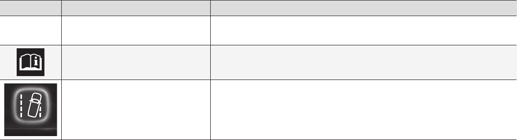
DRIVER SUPPORT
* Option/accessory, for more information, see Introduction. 333
Symbols and messages
Symbol Message Explanation
Driver support system
Reduced functionality Service required
The system is not functioning properly. Contact a trained and qualified Volvo service techni-
cian.
Windscreen sensor
Sensor blocked, see Owner's manual
The camera's functionality is limited.
Lane Keeping Aid
Apply steering
LKA's steering assistance does not function if the driver's hands are not on the steering
wheel. Steer the vehicle actively.
Related information
•Driving lane assistance (p. 328)
•Activating/deactivating Lane Departure
Warning (LDW) (p. 330)
•Activating/deactivating Lane Keeping Aid
(LKA)* (p. 330)


STARTING AND DRIVING
STARTING AND DRIVING
* Option/accessory, for more information, see Introduction.
336
Starting and driving
The vehicle is equipped with features that sup-
plement its basic functions, such as shifting
gears with steering wheel paddles* and the fuel-
conserving start/stop function.
The vehicle is equipped with features that sup-
plement its basic functions, such as shifting
gears with steering wheel paddles*.
The vehicle is equipped with an automatic trans-
mission that also makes it possible to shift gears
manually.
Certain functions can also be used when the
engine is not running, depending on the ignition
mode being used.
Related information
•Starting the engine (p. 362)
•Ignition modes (p. 360)
•Automatic transmission (p. 373)
•Opening/closing the fuel filler door (p. 354)
•Start/Stop (p. 370)
•Parking brake (p. 341)
Brakes
The brake system is a hydraulic system consist-
ing of two separate brake circuits. If a problem
should occur in one of these circuits, it is still
possible to stop the vehicle with the other brake
circuit.
Brake system
If one of the brake circuits is not functioning,
more pressure will be needed on the brake pedal
(and the pedal will go down farther) for normal
braking effect.
If the brake pedal must be depressed farther
than normal and requires greater foot pressure,
the stopping distance will be longer.
Pressure on the brake pedal is enhanced by the
power braking function.
The power brakes only function when the engine
is running.
If the power brakes are not working, considerably
higher pressure will be required on the brake
pedal to compensate for the lack of power assis-
tance. This can happen for example when towing
your vehicle or if the engine is switched off when
the vehicle is rolling. The brake pedal feels stiffer
than usual.
When the Hill Start Assist function is being used,
it will take slightly longer for the brake pedal to
return to its normal position if the vehicle is
parked on an incline or uneven surface.
When driving in very hilly areas or if the vehicle is
carrying a heavy load, manual gear shifting can
be used (move the gear selector toward +/-) for
engine braking to augment the brakes. Hill
Descent Control or the Off Road* driving mode
can also be used to increase the engine braking
effect at low speeds.
Anti-lock Braking System ABS
The ABS system helps to improve vehicle control
(stopping and steering) during severe braking
conditions by limiting brake lockup.
When ABS is operating, there may be some
vibration in the brake pedal, which is normal.
The system performs a brief self-diagnostic test
when the engine has been started and driver
releases the brake pedal. Another automatic test
may be performed when the vehicle first reaches
a speed of approximately 6 mph (10 km/h). The
brake pedal will pulsate several times and a
sound may be audible from the ABS control
module, which is normal.
Cleaning the brake discs
Coatings of dirt and water on the brake discs
may result in delayed brake function. This delay is
minimized by cleaning the brake linings.
Cleaning the brake pads is advisable in wet
weather, prior to long-term parking, and after the
vehicle has been washed. Do this by braking gen-
tly for a short period while the vehicle is moving.
STARTING AND DRIVING
}}
* Option/accessory, for more information, see Introduction. 337
Driving on wet or salted roads
Prolonged driving on wet or salted roads can
affect brake function and increase stopping dis-
tance. Be sure to keep a safe distance to the
vehicle ahead when driving under these condi-
tions.
Brake pad inspection
On vehicles equipped with a jack*, the condition
of the brake pads can be checked by raising the
vehicle and performing a visual inspection of the
brake pads.
WARNING
•If the vehicle has been driven immediately
prior to a brake pad inspection, the wheel
hub, brake components, etc., will be very
hot. Allow time for these components to
cool before carrying out the inspection.
•Apply the parking brake and put the gear
selector in the Park (P) position.
•Block the wheels standing on the ground,
use rigid wooden blocks or large stones.
WARNING
•Use the jack intended for the vehicle
when changing a tire. For any other job,
use stands to support the vehicle.
•The jack should be kept well-greased and
clean, and should not be damaged.
•Be sure the jack is on a firm, level, non-
slippery surface.
•No objects should be placed between the
base of jack and the ground, or between
the jack and the attachment bar on the
vehicle.
•The jack must correctly engage the jack
attachment.
•Never allow any part of your body to be
extended under a vehicle supported by a
jack.
Instrument panel symbols
Symbol Explanation
A
B
Check the brake fluid level. If the
level is low, top up and have the
system inspected to determine the
cause of the loss of fluid.
A
B
Steady glow for 2 seconds when
the engine is started: automatic
function control.
Steady glow for more than
2 seconds: there is a fault in the
ABS system. The normal brake
system will still function but with-
out ABS brake modulation.
AUS models
BCanadian models
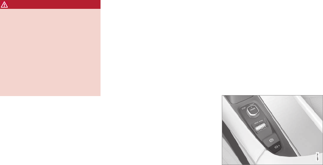
||
STARTING AND DRIVING
* Option/accessory, for more information, see Introduction.
338
WARNING
If both symbols illuminate at the same time
and the brake level is below the MIN mark in
the reservoir or if a brake system-related mes-
sage is shown in the instrument panel: DO
NOT DRIVE. Have the vehicle towed to a
trained and qualified Volvo service technician
and have the brake system inspected.
If both symbols illuminate at the same time
and the brake level is normal (not below the
MIN mark in the reservoir) or if a brake sys-
tem-related message is shown in the instru-
ment panel: drive the vehicle carefully to an
authorized Volvo workshop and have the
brake system inspected by a trained and
qualified Volvo service technician.
Related information
•Brake functions (p. 338)
•Brake assist system (p. 339)
•Emergency brake lights (p. 340)
Brake functions
The vehicle's standard braking features are aug-
mented by a number of auxiliary help functions.
In addition to the wheel brakes and the parking
brake, the vehicle is equipped with several auto-
matic brake assist functions. These systems help
the driver by e.g., keeping the vehicle stationary
when the brake pedal is not depressed (at a traf-
fic light or intersection), when starting up a hill or
when driving down a hill.
These systems include:
•Auto-hold brakes
•Hill Start Assist
•Braking assist after a collision
•Hill Descent Control*
Related information
•Brakes (p. 336)
•Parking brake (p. 341)
•Hill Descent Control (HDC) (p. 340)
•Auto-hold brake function (p. 338)
Auto-hold brake function
With the Auto-hold brake function, the driver can
release the brake pedal and the brakes will
remain applied, for example, when the vehicle
has stopped at a traffic light or intersection.
When the vehicle is no longer moving forward,
Auto-hold applies the brakes automatically, either
using the normal brakes or the parking brake.
The brakes will be released when the accelerator
pedal is depressed.
If the driver's door is opened or the engine is
turned off, the parking brake will be applied auto-
matically.
Auto-hold control
Auto-hold control and indicator light
Turn Auto-hold on or off by pressing the control
in the tunnel console. The indicator light illumi-
nates when the function is on.
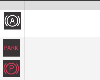
STARTING AND DRIVING
339
When Auto-hold is off, Hill Start Assist (HSA) will
be activated to help prevent the vehicle from roll-
ing backwards when starting up a hill.
Instrument panel symbol
Symbol Explanation
The symbol in the instrument
panel illuminates when this func-
tion is using the normal brakes to
keep the vehicle stationary.
A
B
This symbol in the instrument
panel illuminates when Auto-hold
is using the parking brake to keep
the vehicle stationary
AUS models
BCanadian models
Related information
•Hill Start Assist (p. 341)
•Brake functions (p. 338)
Brake assist system
The Brake Assist System (BAS) increases brak-
ing force, thereby helping reduce braking dis-
tance.
The system monitors the driver's braking habits
and increases braking force when necessary.
Brake force can be increased up to the point at
which the ABS system is activated. The function
is deactivated when pressure on the brake pedal
decreases.
Related information
•Brakes (p. 336)
Braking effect after a collision
In certain types of collisions, the vehicle's brakes
are applied to help prevent or mitigate a secon-
dary collision.
Maintaining control of the vehicle after a collision
may be difficult. To help avoid or mitigate the
effect of a secondary collision, the brakes are
applied automatically to help bring the vehicle to
a stop.
The brake lights and hazard warning flashers will
be activated and the flashers will remain on after
the vehicle has come to a standstill. The parking
brake will then be applied automatically.
In a situation where stopping the vehicle may not
be desirable, the driver can override this system
by pressing the accelerator pedal.
This feature can only function if the brake system
is intact after the collision.
Related information
•Brake functions (p. 338)
•Airbag system (p. 84)
•Rear Collision Warning (RCW) (p. 282)
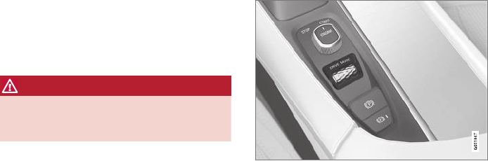
STARTING AND DRIVING
* Option/accessory, for more information, see Introduction.
340
Emergency brake lights
The emergency brake lights activate in the event
of hard braking/rapid deceleration at most nor-
mal driving speeds or if the ABS system is acti-
vated. This function causes an additional taillight
on each side of the vehicle to illuminate to help
alert vehicles traveling behind.
Once the emergency brake lights have been acti-
vated, if the driver releases the brake pedal, the
brake lights will return to their normal function.
Related information
•Brakes (p. 336)
•Hazard warning flashers (p. 141)
•Brake lights (p. 140)
Hill Descent Control (HDC)
HDC is a type of low-speed automatic engine
brake and makes it possible to increase or
decrease the vehicle's speed on steep downhill
gradients using only the accelerator pedal, with-
out applying the brakes.
HDC is particularly useful when driving down
steep hills with rough surfaces, and where the
road may have slippery patches.
WARNING
HDC does not function in all situations, and is
a supplementary braking aid. The driver has
full responsibility for driving in a safe manner.
Function
HDC allows the vehicle to roll forward or in
reverse at very low speed with enhanced engine
braking. However, speed can be adjusted with
the accelerator pedal. When the accelerator
pedal is released, the vehicle will return to very
low speed.
The driver can use the brakes to slow or stop the
vehicle at any time.
HDC is activated along with Low Speed Control
(LSC), which together make driving on slippery
surfaces at low speeds easier.
When HDC and LSC are activated, this changes
the response from the accelerator pedal and
engine.
Activating HDC
This function can be activated in different ways,
depending on how the vehicle is equipped.
Using the drive mode control*
Select the Off Road drive mode to activate the
function.
Select a different drive mode to turn HDC off. If
this is done while the vehicle is on a steep down-
grade, engine braking will decrease gradually.
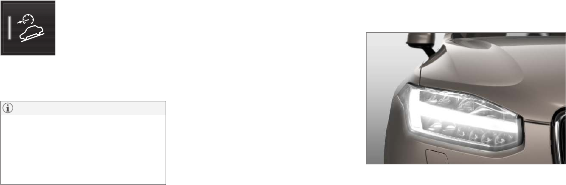
STARTING AND DRIVING
}}
* Option/accessory, for more information, see Introduction. 341
From the center display's Function view
Models without the drive mode
control have a button for Hill
Descent Control in the center
display's Function view.
•Tap the button to activate. A light in the but-
ton illuminates when the function is acti-
vated.
NOTE
When LSC with HDC is activated, the feel of
the accelerator pedal and engine response
will change.
The function is deactivated when driving at
higher speeds and must be reactivated at
lower speeds if so desired.
Related information
•Brake functions (p. 338)
•Low Speed Control (LSC) (p. 378)
•Drive modes* (p. 365)
Hill Start Assist
Hill Start Assist (HSA) helps prevent the vehicle
from rolling backwards when starting up a hill. If
you are backing up a hill, HSA helps prevent the
vehicle from rolling forward.
HSA makes it easier to start or back up on a hill
by retaining pressure on the brake pedal for sev-
eral seconds after the pedal has been released in
order to keep the vehicle at a standstill.
The brakes will be released after several seconds
or when the driver presses the accelerator pedal.
HSA is available even if the Auto-hold braking
function is turned off.
Related information
•Brake functions (p. 338)
•Auto-hold brake function (p. 338)
Parking brake
The electric parking brake helps to keep the
vehicle stationary when it is parked.
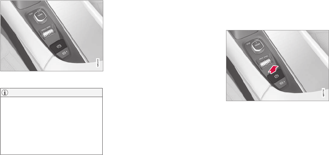
||
STARTING AND DRIVING
342
Parking brake control in the tunnel console between the
front seats
NOTE
•A faint sound from the parking brake's
electric motor can be heard when the
parking brake is being applied. This
sound can also be heard during the auto-
matic function check of the parking
brake.
•The brake pedal will move slightly when
the electric parking brake is applied or
released.
If the vehicle is not moving when the parking
brake is applied, only the rear wheels are affec-
ted. If it is applied while the vehicle is moving, the
normal brakes are used on all four wheels. The
brakes will only be applied on the rear wheels
once the vehicle has stopped.
Related information
•Brake functions (p. 338)
•Using the parking brake (p. 342)
•Parking brake malfunctions (p. 344)
Using the parking brake
The electric parking brake helps to keep the
vehicle stationary when it is parked.
Applying the parking brake
1. Put the gear selector in P.
2. Press firmly on the brake pedal.
3. Pull up the control.
> The symbol in the instrument panel
flashes while the parking brake is being
applied and glows steadily when the park-
ing brake has been fully applied.
4. Release the brake pedal and ensure that the
vehicle is stationary.
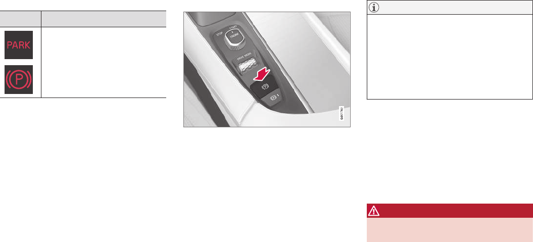
STARTING AND DRIVING
}}
343
Symbol in the instrument panel
Symbol Explanation
A
B
The symbol flashes while the park-
ing brake is being applied.
If the symbol flashes at any other
time, this indicates a fault. See the
message in the instrument panel.
AUS models
BCanadian models
Automatic function
The parking brake is applied automatically:
•If the Auto Hold function is activated and the
vehicle has been stationary for approx.
5 minutes.
•If the gear selector is moved to P on a steep
hill.
•When the engine is turned off (this function
can be selected, see "Parking brake set-
tings" below).
Emergency braking
In an emergency, the parking brake can be
applied when the vehicle is moving by pressing
and holding up the control. Braking will be inter-
rupted when the control is released.
An audible signal will sound during this proce-
dure if the vehicle is moving at higher speeds.
Releasing the parking brake
Releasing manually
1. Press firmly on the brake pedal.
2. Press the control.
> This releases the parking brake and the
symbol in the instrument panel will go out.
Releasing automatically
1. The driver must fasten his/her seat belt.
2. Start the engine.
3. Press firmly on the brake pedal.
4. Move the gear selector to D or R and press
the accelerator pedal.
> This releases the parking brake and the
symbol in the instrument panel will go out.
NOTE
•For safety reasons, the parking brake is
only released automatically if the engine
is running and the driver is wearing a seat
belt.
•The electric parking brake will be
released immediately when the accelera-
tor pedal is pressed and the gear selector
is in position D or R.
Parking on a hill
Put the gear selector in P.
•If the vehicle is pointing uphill, turn the front
wheels so that they point away from the curb.
•If the vehicle is pointing downhill, turn the
front wheels so that they point toward the
curb.
The parking brake should also be applied.
WARNING
Always apply the parking brake when parking
on hills or uneven surfaces.
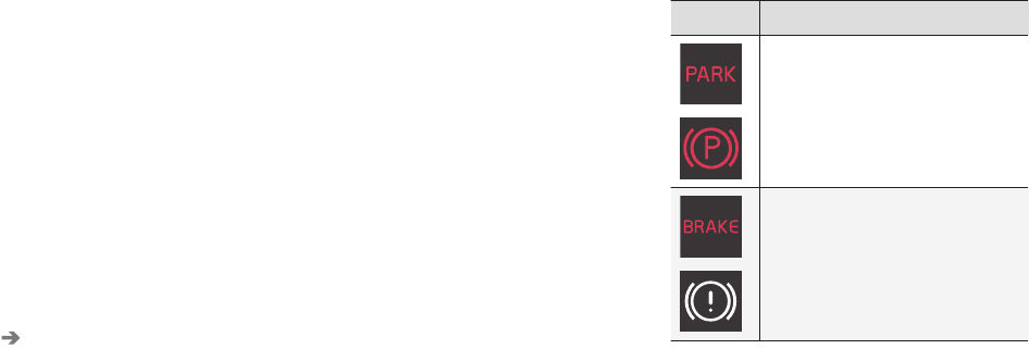
||
STARTING AND DRIVING
344
Heavy load uphill
A heavy load, such as a trailer, can cause the
vehicle to roll backward when the parking brake
is released automatically on a steep incline. To
help avoid this:
1. Keep the electric parking brake control
pushed in.
2. While pressing the accelerator pedal to pull
away, release the parking brake control only
after the vehicle begins to move.
Parking brake settings
Automatically setting the parking brake can be
turned on or off in the center display's Top view.
1. Tap Settings in Top view.
2. Tap My Car Electric Parking Brake and
deselect Auto Activate Parking Brake.
Related information
•Parking brake (p. 341)
•Parking brake malfunctions (p. 344)
•Auto-hold brake function (p. 338)
Parking brake malfunctions
If it has not been possible to apply or release the
parking brake after several attempts, consult a
trained and authorized Volvo service technician
or retailer.
An audible signal will sound if the parking brake
is applied when the vehicle is being driven. If the
vehicle must be parked while the parking brake is
not functioning properly:
•Put the gear selector in P.
•If the vehicle is pointing uphill, turn the front
wheels so that they point away from the curb.
•If the vehicle is pointing downhill, turn the
front wheels so that they point toward the
curb.
•Put the gear selector in P.
Low battery charge level
If the battery is discharged, the parking brake
cannot be operated. Connect an auxiliary battery
to the vehicle.
Replacing brake pads
The rear brake pads have to be replaced by a
trained and authorized Volvo service technician
due to the design of the electric parking brake.
Symbols in the instrument panel
Symbol Explanation
A
B
If the symbol flashes, a parking
brake fault has been detected.
See the message in the instru-
ment panel.
A
B
Fault in the brake system.
AUS models
BCanadian models
Related information
•Using the parking brake (p. 342)
•Using the parking brake (p. 342)
•Brake functions (p. 338)
•Jump starting (p. 355)
STARTING AND DRIVING
}}
345
Before a long distance trip
It is always worthwhile to have your vehicle
checked by a trained and qualified Volvo service
technician before driving long distances. Your
retailer will also be able to supply you with bulbs,
fuses, spark plugs and wiper blades for your use
in the event that problems occur.
As a minimum, the following items should be
checked before any long trip:
•Check that engine runs smoothly and that
fuel consumption and the oil level are normal.
•Check for fuel, oil, and fluid leakage.
•Check condition of drive belts.
•Check state of the battery's charge.
•Examine tires carefully (including the spare
tire where applicable), and replace those that
are worn. Also, check tire inflation pressure.
•The brakes, front wheel alignment, and steer-
ing gear should be checked by a trained and
qualified Volvo service technician only.
•Check all lights, including high beams.
•Reflective warning triangles are legally
required in some states/provinces.
•Have a word with a trained and qualified
Volvo service technician if you intend to drive
in countries where it may be difficult to
obtain the correct fuel.
•Consider your destination. If you will be driv-
ing through an area where snow or ice are
likely to occur, consider using snow tires.
Driving economically
Better driving economy can be obtained by
thinking ahead, avoiding rapid starts and stops
and adjusting the speed of your vehicle to imme-
diate traffic conditions.
Economical driving conserves natural
resources
Observe the following rules:
•Bring the engine to normal operating tem-
perature as soon as possible by driving with
a light foot on the accelerator pedal for the
first few minutes of operation. A cold engine
uses more fuel and is subject to increased
wear.
•Whenever possible, avoid using the vehicle
for driving short distances. This does not
allow the engine to reach normal operating
temperature.
•Drive carefully and avoid rapid acceleration
and hard braking.
•Use the transmission's Drive (D) position as
often as possible and avoid using kick-down.
•Using the engine's Eco function can help
improve fuel economy.
•Do not exceed posted speed limits.
•Avoid carrying unnecessary items (extra load)
in the vehicle.
•Maintain correct tire pressure. Check tire
pressure regularly (when the tires are cold).
•Remove snow tires when threat of snow or
ice has ended.
•Note that roof racks, ski racks, etc, increase
air resistance and also fuel consumption.
•At highway driving speeds, fuel consumption
will be lower with the air conditioning on and
the windows closed than with the air condi-
tioning off and the windows open.
•Using the onboard trip computer's fuel con-
sumption modes can help you learn how to
drive more economically.
Other factors that decrease gas mileage are:
•Dirty air cleaner
•Dirty engine oil and clogged oil filter
•Dragging brakes
•Incorrect front end alignment
Some of the above mentioned items and others
are checked at the standard maintenance inter-
vals.
Handling and roadholding
•Vehicle load, tire design and inflation pres-
sure all affect vehicle handling. Therefore,
check that the tires are inflated to the rec-
ommended pressure according to the vehicle
load. Loads should be distributed so that
capacity weight or maximum permissible axle
loads are not exceeded.
•At the specified curb weight your vehicle has
a tendency to understeer, which means that
the steering wheel has to be turned more

STARTING AND DRIVING
346
than might seem appropriate for the curva-
ture of a bend. This ensures good stability
and reduces the risk of rear wheel skid.
Remember that these properties can alter
with the vehicle load. The heavier the load in
the cargo compartment, the less the ten-
dency to understeer.
Driving through standing water
The vehicle should be driven with extreme cau-
tion if it is necessary to drive through standing
water.
The vehicle can be driven through water up to a
depth of approximately 17.7 in. (45 cm) at walk-
ing speed to help prevent water from entering
the differential and the transmission. This
reduces the oil's lubricating capacity and may
shorten the service life of these components.
•Take particular care when driving through
flowing water.
•After driving through water, apply the brakes
and check that they are functioning correctly.
•Clean the electrical connections for trailer
wiring after driving in mud or water.
•When driving through water, maintain low
speed and do not stop in the water.
•Avoid driving through salt water if at all pos-
sible to help avoid the risk of corrosion.
CAUTION
•Engine damage will occur if water is
drawn into the air cleaner.
•Damage to any components, the engine,
transmission, turbo-charger, differential or
its internal components caused by flood-
ing, vapor lock or insufficient oil is not
covered under warranty.
•Do not allow the vehicle to stand in water
up to the door sills longer than absolutely
necessary. This could result in electrical
malfunctions.
•If the engine has been stopped while the
vehicle is in water, do not attempt to
restart it. Have the vehicle towed out of
the water.
WARNING
•Avoid driving through standing or rushing
water. Doing so can be dangerous and it
may also be difficult to determine the
actual depth of the water.
•If water cannot be avoided, after driving
through the water, press lightly on the
brake pedal to ensure that the brakes are
functioning normally. Water or mud can
make the brake linings slippery, resulting
in delayed braking effect.

STARTING AND DRIVING
347
Related information
•Towing recommendations (p. 349)
Overheating the engine and
transmission
In demanding driving conditions, such as when
transporting heavy loads, driving in mountainous
areas or in very hot weather there is a risk of
overheating the engine or transmission.
•The engine's output may be slightly limited if
there is a risk of overheating.
•Remove e.g., auxiliary lights mounted in front
of the grille in hot weather.
•If the temperature of the engine coolant
becomes too high, the warning symbol will
illuminate and the message Engine
temperature/Stop safely will be displayed.
Stop the vehicle as soon as possible in a
safe place and let the engine idle for several
minutes.
•If the message Engine temperature/High
temperature Turn off engine or Engine
coolant/Stop safely is displayed, stop
safely and turn off the engine.
•If the transmission begins to overheat, an
alternative gear shifting program will be
selected. An integrated protective function
will also by activated, the warning symbol will
illuminate and the message Transmission
warmHigh temperature Reduce speed
or Transmission warmStop safely, wait
for cooling will be displayed in the instru-
ment panel.
•The air conditioning may be switched off
temporarily.
•After a prolonged period of driving, do not
turn off the engine immediately after stop-
ping.
•The engine cooling fan commonly continues
to run for several minutes after the engine
has been turned off.
WARNING
The cooling fan (located at the front of the
engine compartment, behind the radiator) may
start or continue to operate (for up to
6 minutes) after the engine has been
switched off.
Related information
•Driving with a trailer (p. 357)
•Before a long distance trip (p. 345)
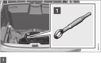
STARTING AND DRIVING
348
Winter driving
Check your vehicle before the approach of cold
weather.
The following advice is worth noting:
•Make sure that the engine coolant contains
50 percent antifreeze. Any other mixture will
reduce freeze protection. This gives protec-
tion against freezing down to –31 °F
(–35 °C). The use of "recycled" antifreeze is
not approved by Volvo. Different types of
antifreeze must not be mixed.
•Volvo recommends using only genuine Volvo
antifreeze in your vehicle's radiator.
•Try to keep the fuel tank well filled – this
helps prevent the formation of condensation
in the tank. In addition, in extremely cold
weather conditions it is worthwhile to add
fuel line de-icer before refueling.
•The viscosity of the engine oil is important.
Oil with low viscosity (thinner oil) improves
cold-weather starting as well as decreasing
fuel consumption while the engine is warm-
ing up. Full synthetic 0W-30 oil is recom-
mended for driving in areas with sustained
low temperatures.
•The load placed on the battery is greater dur-
ing the winter since the windshield wipers,
lighting, etc., are used more often. Moreover,
the capacity of the battery decreases as the
temperature drops. In very cold weather, a
poorly charged battery can freeze and be
damaged. It is therefore advisable to check
the state of charge more frequently and
spray an anti-rust oil on the battery posts.
•Volvo recommends the use of snow tires on
all four wheels for winter driving.
•To prevent the washer fluid reservoir from
freezing, add washer solvents containing
antifreeze. This is important since dirt is often
splashed on the windshield during winter
driving, requiring the frequent use of the
washers and wipers. Volvo Washer Solvent
should be diluted as follows: Down to 14 °F
(–10 °C): 1 part washer solvent and 4 parts
water Down to 5 °F (–15 °C): 1 part washer
solvent and 3 parts water Down to 0 °F
(–18 °C): 1 part washer solvent and 2 parts
water Down to –18 °F (–28 °C): 1 part
washer solvent and 1 part water.
•Use Volvo Teflon Lock Spray in the locks.
•Avoid using de-icing sprays as they can
cause damage to the locks.
Related information
•Snow tires and chains (p. 481)
Towing eyelet
When used, the towing eyelet should always be
securely attached in the openings on the right
side of the front and rear bumpers. There are
covers over these attachment points.
Take out the towing eyelet, which is stored
under the floor in the cargo compartment.
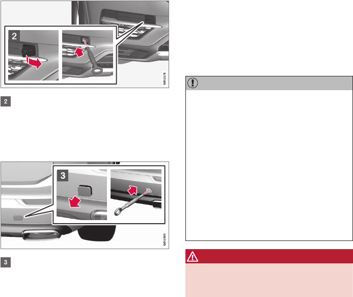
STARTING AND DRIVING
}}
349
Front bumper: Carefully pry open the cover
by inserting a small screwdriver or the
remote key's removable key blade into the
groove on its left side.
> The cover can now be folded out and
removed.
Rear bumper: Remove the cover by pressing
the mark in the lower left corner with a finger
and folding out the upper right corner.
> The cover folds out and can then be
removed.
4. Screw the towing eyelet into place, first by
hand and then using the tire iron, etc. until it
has been screwed in as far as possible.
After use, the eyelet should be removed and
returned to its storage location.
Reinsert the cover into the bumper.
CAUTION
In certain conditions, the towing eyelet
may be used to pull the vehicle onto a
flatbed tow truck.
•The vehicle's position and ground clear-
ance determine if it can be pulled up onto
a flatbed tow truck using the towing eye-
let.
•If the angle of the tow truck’s ramp is too
steep or the ground clearance under the
vehicle is insufficient, damage could
occur by attempting to pull the vehicle
using the towing eyelet.
•If necessary, lift the vehicle using the tow
truck’s lifting device.
WARNING
No person or object should be behind the tow
truck while the vehicle is being pulled up onto
the flatbed.
Related information
•Towing recommendations (p. 349)
Towing recommendations
Always check with state and local authorities
before attempting to tow another vehicle
because this type of towing is subject to regula-
tions regarding maximum towing speed, length
and type of towing device, lighting, etc.
Towing your vehicle behind another
vehicle
1. After securely attaching the towing line to
both vehicles, put the gear selector in posi-
tion N and release the parking brake.
2. Put the ignition in mode II by turning the
start knob to START (without depressing
the brake pedal) and hold it in this position
for approx. 4 seconds. Release the knob.
3. Put the gear selector in position N and
release the parking brake.
4. The towing vehicle can now begin driving.
5. Keep the tow rope taut when the towing
vehicle slows down by applying light pressure
on the brake pedal. This will help prevent jar-
ring movements of the vehicle being towed.
6. Be prepared to apply the brakes to stop the
vehicle being towed.
||
STARTING AND DRIVING
350
CAUTION
General towing precautions:
•If the vehicle's battery is dead, an auxiliary
battery will be necessary to provide cur-
rent for releasing the electric parking
brake and to move the gear selector from
the P position to N. If this is not possible,
use the shiftlock override procedure to
manually release the gear selector from P
and move it to N.
•Maximum speed: 50 mph (80 km/h). Do
not exceed the maximum allowable tow-
ing speed.
•Maximum distance with front wheels on
ground: 50 miles (80 km).
•The vehicle should only be towed in the
forward direction.
WARNING
•When the vehicle is being towed, the igni-
tion should be in mode II (in mode I, all of
the vehicle's airbags are deactivated).
•The remote key must remain inside the
vehicle.
•The power brakes and power steering will
not function when the engine is not run-
ning. Approximately 5 times more pres-
sure will be required on the brake pedal
and the steering wheel will be considera-
bly harder to turn.
•The towing eyelets must not be used for
pulling the vehicle out of a ditch or for
any similar purpose involving severe
strain.
Tow trucks
CAUTION
In certain conditions, the towing eyelet
may be used to pull the vehicle onto a
flatbed tow truck.
•The vehicle's position and ground clear-
ance determine if it can be pulled up onto
a flatbed tow truck using the towing eye-
let.
•If the angle of the tow truck’s ramp is too
steep or the ground clearance under the
vehicle is insufficient, damage could
occur by attempting to pull the vehicle
using the towing eyelet.
•If necessary, lift the vehicle using the tow
truck’s lifting device.
WARNING
No person or object should be behind the tow
truck while the vehicle is being pulled up onto
the flatbed.
STARTING AND DRIVING
* Option/accessory, for more information, see Introduction. 351
Vehicle with pneumatic suspension*
If the vehicle is equipped with the optional pneu-
matic suspension, this feature must be deacti-
vated before the vehicle is lifted onto a tow truck.
To do so:
1. Tap Settings in the center display's Top
view.
2. Tap My Car Suspension .
3. Select Deactivate Suspension & Leveling
Control.
CAUTION
•Models equipped with All Wheel Drive
(AWD) may not be towed with the front
wheels off the ground at speeds above
approx. 40 mph (70 km/h). It should not
be towed farther than approx. 30 miles
(50 km).
•The towing eyelet is only intended for use
if the vehicle is on a road, not if is off the
road surface or stuck in mud, snow, etc.
In these cases, contact professional tow-
ing help.
Jump starting
Do not attempt to start the engine by towing the
vehicle. This could result in damage to the three-
way catalytic converter. Use a 12-volt auxiliary
battery or one in another vehicle.
WARNING
PROPOSITION 65 WARNING!
Battery posts, terminals, and related accesso-
ries contain lead and lead compounds, chemi-
cals known to the state of California to cause
cancer and reproductive harm. Wash hands
after handling.
CAUTION
Connect the jumper cables carefully to avoid
short circuits with other components in the
engine compartment.
WARNING
•Do not connect the jumper cable to any
part of the fuel system or to any moving
parts. Avoid touching hot manifolds.
•Batteries generate hydrogen gas, which
is flammable and explosive.
•Battery fluid contains sulfuric acid. Do not
allow battery fluid to contact eyes, skin,
fabrics or painted surfaces. If contact
occurs, flush the affected area immedi-
ately with water. Obtain medical help
immediately if eyes are affected.
•Never expose the battery to open flame
or electric spark.
•Do not smoke near the battery.
•Failure to follow the instructions for jump
starting can lead to injury.
Related information
•Towing eyelet (p. 348)
•Jump starting (p. 355)
•Parking brake (p. 341)
•Ignition modes (p. 360)

STARTING AND DRIVING
352
Fuel
Volvo recommends the use of detergent gaso-
line to control engine deposits.
Deposit control gasoline (detergent
additives)
Detergent gasoline is effective in keeping injec-
tors and intake valves clean. Consistent use of
deposit control gasolines will help ensure good
drivability and fuel economy. If you are not sure
whether the gasoline contains deposit control
additives, check with the service station operator.
NOTE
Volvo does not recommend the use of exter-
nal fuel injector cleaning systems.
Unleaded fuel
Each Volvo has a three-way catalytic converter
and must use only unleaded gasoline. U.S. and
Canadian regulations require that pumps deliver-
ing unleaded gasoline be labeled "UNLEADED".
Only these pumps have nozzles which fit your
vehicle's filler inlet. It is unlawful to dispense lea-
ded fuel into a vehicle labeled "unleaded gaso-
line only". Leaded gasoline damages the three-
way catalytic converter and the heated oxygen
sensor system. Repeated use of leaded gasoline
will lessen the effectiveness of the emission con-
trol system and could result in loss of emission
warranty coverage. State and local vehicle
inspection programs will make detection of mis-
fueling easier, possibly resulting in emission test
failure for misfueled vehicles.
NOTE
Some U.S. and Canadian gasolines contain an
octane enhancing additive called methyl-
cyclopentadienyl manganese tricarbonyl
(MMT). If such fuels are used, your Emission
Control System performance may be affected,
and the Check Engine Light (malfunction
indicator light) located on your instrument
panel may light. If this occurs, please return
your vehicle to a trained and qualified Volvo
service technician for service.
Gasoline containing alcohol and ethers,
"Oxygenated fuels"
Some fuel suppliers sell gasoline containing
"oxygenates" which are usually alcohols or
ethers. In some areas, state or local laws require
that the service pump be marked indicating use
of alcohols or ethers. However, there are areas in
which the pumps are unmarked. If you are not
sure whether there is alcohol or ethers in the
gasoline you buy, check with the service station
operator. To meet seasonal air quality standards,
some areas require the use of "oxygenated" fuel.
Volvo allows the use of the following "oxygen-
ated" fuels; however, the octane ratings listed
must still be met.
Alcohol – Ethanol
Fuels containing up to 10% ethanol by volume
may be used. Ethanol may also be referred to as
Ethyl alcohol, or "Gasohol".
Ethers – MTBE: Fuels containing up to
15% MTBE may be used.
Methanol
Do not use gasolines containing methanol
(methyl alcohol, wood alcohol). This practice can
result in vehicle performance deterioration and
can damage critical parts in the fuel system. Such
damage may not be covered under the New
Vehicle Limited Warranty.
Related information
•Octane rating (p. 353)
•Opening/closing the fuel filler door (p. 354)
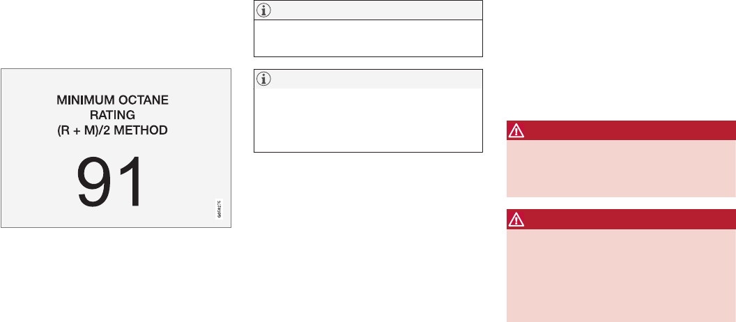
STARTING AND DRIVING
353
Octane rating
Volvo requires premium fuel (91 octane or
above) for best performance.
Minimum octane
Sample fuel pump octane label
TOP TIER Detergent Gasoline
Volvo endorses the use of “TOP TIER Detergent
Gasoline” where available to help maintain engine
performance and reliability. TOP TIER Detergent
Gasoline meets a new standard jointly estab-
lished by leading automotive manufactures to
meet the needs of today’s advanced engines.
Qualifying gasoline retailers (stations) will, in
most cases, identify their gasoline as having met
the “TOP TIER Detergent Gasoline” standards.
NOTE
Information about TOP TIER Detergent Gaso-
line is available at www.toptiergas.com.
NOTE
When switching to higher octane fuel or
changing gasoline brands, it may be neces-
sary to fill the tank more than once before a
difference in engine operation is noticeable.
Fuel Formulations
Do not use gasoline that contains lead as a
knock inhibitor, and do not use lead additives.
Besides damaging the exhaust emission control
systems on your vehicle, lead has been strongly
linked to certain forms of cancer.
Many fuels contain benzene as a solvent.
Unburned benzene has been strongly linked to
certain forms of cancer. If you live in an area
where you must fill your own gas tank, take pre-
cautions. These may include:
•standing upwind away from the filler nozzle
while refueling
•refueling only at gas stations with vapor
recovery systems that fully seal the mouth of
the filler neck during refueling
•wearing neoprene gloves while handling a
fuel filler nozzle.
Use of Additives
With the exception of gas line antifreeze during
winter months, do not add solvents, thickeners, or
other store-bought additives to your vehicle's
fuel, cooling, or lubricating systems. Overuse may
damage your engine, and some of these additives
contain organically volatile chemicals. Do not
needlessly expose yourself to these chemicals.
WARNING
Never carry a cell phone that is switched on
while refueling your vehicle. If the phone rings,
this may cause a spark that could ignite gaso-
line fumes, resulting in fire and injury.
WARNING
Carbon monoxide is a poisonous, colorless,
and odorless gas. It is present in all exhaust
gases. If you ever smell exhaust fumes inside
the vehicle, make sure the passenger com-
partment is ventilated, and immediately return
the vehicle to a trained and qualified Volvo
service technician for correction.
Related information
•Fuel (p. 352)
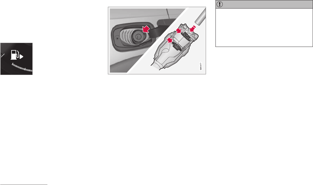
STARTING AND DRIVING
354
Opening/closing the fuel filler door
The fuel tank has a filling system that does not
have a cover.
Opening/closing the fuel filler door
The vehicle must be unlocked before the fuel
filler door can be opened.
An arrow next to the fuel pump
symbol in the instrument panel
indicates the side of the vehicle
where the fuel filler door is
located.
1. Open the fuel filler door by pressing lightly
on its rear edge.
2. After refueling, close the fuel filler door by
pressing lightly.
Refueling from a service station pump
To refuel:
1. Open the fuel filler door. Do not refuel with
the engine running1
2. Insert the pump's nozzle into the fuel filler
pipe's opening as far as possible (see the
illustration).
3. Avoid overfilling the fuel tank. Do not press
the handle on the filler nozzle after it has
stopped pumping. Too much fuel in the tank
in hot weather conditions can cause the fuel
to overflow. Overfilling could also cause dam-
age to the emission control systems.
CAUTION
Avoid spilling gasoline during refueling. In
addition to causing damage to the environ-
ment, gasolines containing alcohol can cause
damage to painted surfaces, which may not
be covered under the New Vehicle Limited
Warranty.
Related information
•Fuel (p. 352)
•Octane rating (p. 353)
1If the engine is running when the vehicle is refueled, the Check Engine Light (malfunction indicator lamp) may indicate a fault. However, your vehicle's performance will not be affected.
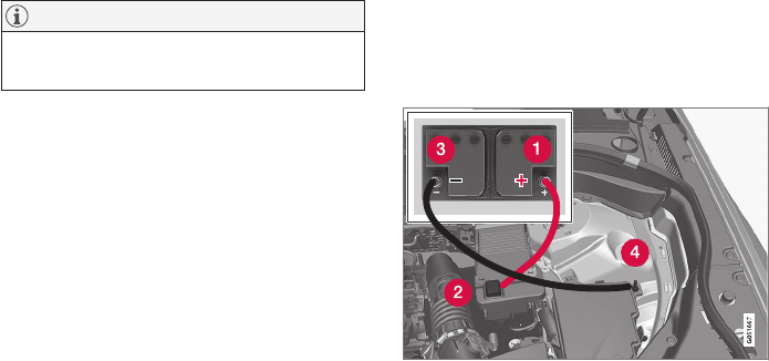
STARTING AND DRIVING
}}
355
Emission controls
Three-way catalytic converter
•Keep your engine properly tuned. Certain
engine malfunctions, particularly involving the
electrical, fuel or distributor ignition systems,
may cause unusually high three-way catalytic
converter temperatures. Do not continue to
operate your vehicle if you detect engine
misfire, noticeable loss of power or other
unusual operating conditions, such as engine
overheating or backfiring. A properly tuned
engine will help avoid malfunctions that
could damage the three-way catalytic con-
verter.
•Do not park your vehicle over combustible
materials, such as grass or leaves, which can
come into contact with the hot exhaust sys-
tem and cause such materials to ignite under
certain wind and weather conditions.
•Excessive starter cranking (in excess of one
minute), or an intermittently firing or flooded
engine can cause three-way catalytic con-
verter or exhaust system overheating.
•Remember that tampering or unauthorized
modifications to the engine, the Engine Con-
trol Module, or the vehicle may be illegal and
can cause three-way catalytic converter or
exhaust system overheating. This includes:
altering fuel injection settings or compo-
nents, altering emission system components
or location or removing components, and/or
repeated use of leaded fuel.
NOTE
Unleaded fuel is required for vehicles with
three-way catalytic converters.
Heated oxygen sensors
The heated oxygen sensors monitor the oxygen
content of the exhaust gases. Readings are fed
into a control module that continuously monitors
engine functions and controls fuel injection. The
ratio of fuel to air into the engine is continuously
adjusted for efficient combustion to help reduce
harmful emissions.
Related information
•Octane rating (p. 353)
Jump starting
Follow the instructions provided here to jump
start your vehicle or to jump start another vehi-
cle.
Jumper cable connecting points
If the 12-volt auxiliary battery to be used is in
another vehicle, check that the vehicles are not
touching to prevent premature completion of a
circuit. Be sure to follow jump starting instruc-
tions provided for the other vehicle.
1. Switch off the ignition in your vehicle (set the
ignition to mode 0).

||
STARTING AND DRIVING
356
2. If the 12-volt auxiliary battery to be used is
in another vehicle, switch off that vehicle's
ignition while the jumper cables are being
attached. Be sure to follow jump starting
instructions provided for the other vehicle.
CAUTION
Connect the jumper cables carefully to avoid
short circuits with other components in the
engine compartment.
3. Connect one of the red jumper cable's
clamps to the auxiliary battery's positive (+)
terminal (1)
4. Fold back the cover over the positive (+)
jump start terminal on your vehicle's battery
(2).
5. Connect the red jumper cable's other clamp
to your vehicle's positive (+) jump start termi-
nal (2).
6. Connect one of the black jumper cable's
clamps to the auxiliary battery's negative (–)
terminal (3).
7. Connect the black jumper cable's other
clamp to your vehicle's negative ground point
(4).
8. Check that the jumper cables are securely
attached.
9. Start the engine in the assisting vehicle and
run it at approx. 1,500 rpm.
10. Start the engine in the vehicle with dead bat-
tery.
11. After the engine has started, carefully
remove the negative (–) terminal jumper
cable (black). Then remove the positive (+)
terminal jumper cable (red).
WARNING
PROPOSITION 65 WARNING!
Battery posts, terminals, and related accesso-
ries contain lead and lead compounds, chemi-
cals known to the state of California to cause
cancer and reproductive harm. Wash hands
after handling.
WARNING
•Do not connect the jumper cable to any
part of the fuel system or to any moving
parts. Avoid touching hot manifolds.
•Batteries generate hydrogen gas, which
is flammable and explosive.
•Battery fluid contains sulfuric acid. Do not
allow battery fluid to contact eyes, skin,
fabrics or painted surfaces. If contact
occurs, flush the affected area immedi-
ately with water. Obtain medical help
immediately if eyes are affected.
•Never expose the battery to open flame
or electric spark.
•Do not smoke near the battery.
•Failure to follow the instructions for jump
starting can lead to injury.
Related information
•Ignition modes (p. 360)
•Starting the engine (p. 362)
•Turning the engine off (p. 364)
•Start battery (p. 503)
•Opening and closing the hood (p. 528)

STARTING AND DRIVING
}}
357
Driving with a trailer
When towing a trailer, always observe the legal
requirements of the state/province.
•All Volvo models are equipped with energy-
absorbing shock-mounted bumpers. Trailer
hitch installation should not interfere with the
proper operation of this bumper system.
Trailer towing does not normally present any par-
ticular problems, but take into consideration:
•Increase tire pressure to recommended full
pressure.
•When your vehicle is new, avoid towing heavy
trailers during the first 620 miles (1,000 km).
•Maximum speed when towing a trailer:
50 mph (80 km/h).
•Engine and transmission are subject to
increased loads. Therefore, engine coolant
temperature should be closely watched when
driving in hot climates or hilly terrain. Use a
lower gear and turn off the air conditioner if
the temperature gauge needle enters the red
range.
•If the automatic transmission begins to over-
heat, a message will be displayed in the text
window.
•Avoid overload and other abusive operation.
•Hauling a trailer affects handling, durability,
and economy.
•It is necessary to balance trailer brakes with
the towing vehicle brakes to provide a safe
stop (check and observe state/local regula-
tions).
•Do not connect the trailer's brake system
directly to the vehicle's brake system.
•More frequent vehicle maintenance is
required.
•Remove the ball holder when the hitch is not
being used.
NOTE
•When parking the vehicle with a trailer on
a hill, apply the parking brake before put-
ting the gear selector in P. Always follow
the trailer manufacturer's recommenda-
tions for wheel chocking.
•When starting on a hill, put the gear
selector in D before releasing the parking
brake.
•If you use the manual (Geartronic) shift
positions while towing a trailer, make sure
the gear you select does not put too
much strain on the engine (using too
high a gear).
•The drawbar assembly/trailer hitch may
be rated for trailers heavier than the vehi-
cle is designed to tow. Please adhere to
Volvo's recommended trailer weights.
•Avoid driving with a trailer on inclines of
more than 15%.
CAUTION
The maximum trailer weights listed are only
applicable for altitudes up to 3,280 ft
(1000 m) above sea level. With increasing
altitude the engine power and therefore the
car's climbing ability are impaired because of
the reduced air density, so the maximum
trailer weight has to be reduced accordingly.
The weight of the vehicle and trailer must be
reduced by 10% for every further 3,280 ft
(1,000 m) (or part thereof). When towing
5,000 lbs (2,250 kg) hill inclination is restric-
ted to 14%.
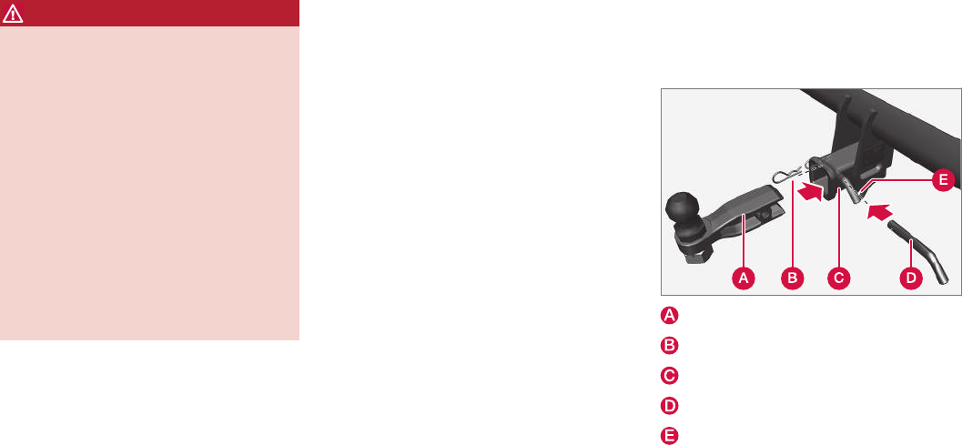
||
STARTING AND DRIVING
* Option/accessory, for more information, see Introduction.
358
WARNING
•Bumper-attached trailer hitches must not
be used on Volvos, nor should safety
chains be attached to the bumper.
•Trailer hitches attaching to the vehicle
rear axle must not be used.
•Never connect a trailer's hydraulic brake
system directly to the vehicle brake sys-
tem, nor a trailer's lighting system directly
to the vehicle lighting system. Consult
your nearest authorized Volvo retailer for
correct installation.
•When towing a trailer, the trailer's safety
chains or wire must be correctly fastened
to the attachment points provided in the
trailer hitch on the vehicle. The safety
chain or wire must never be fastened to
or wound around the towing ball.
Trailer cable
An adapter is required if the vehicle's trailer hitch
has a 13-pin connector and the trailer has 7 pins.
Use an adapter cable approved by Volvo. Make
sure the cable does not drag on the ground.
Self-leveling suspension*
With this system, the rear suspension maintains a
constant level, regardless of the load in the cargo
compartment (up to the max. permissible load).
When the engine is not running, the rear of the
vehicle sinks down slightly, which is normal.
Related information
•Detachable trailer hitch (p. 358)
•Trailer Stability Assist (TSA) (p. 359)
•Weights (p. 549)
Detachable trailer hitch
Volvo recommends the use of Volvo trailer
hitches that are specially designed for the vehi-
cle.
Ball holder
Cotter pin
Hitch assembly
Locking bolt
Safety wire attachment
Installing the ball holder
1. If necessary, remove the cotter pin from the
locking bolt and slide the locking bolt out of
the hitch assembly.
2. Slide the ball holder into the hitch assembly.
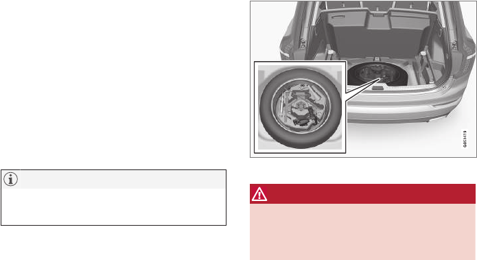
STARTING AND DRIVING
}}
359
3. Align the hole in the ball holder with the one
in the hitch assembly.
4. Slide the locking bolt through the hitch
assembly/ball holder.
5. Insert the cotter pin in the hole at the end of
the locking bolt.
Removing the ball holder
1. Remove the cotter pin from the locking bolt
and slide the locking bolt out of the ball
holder/hitch assembly.
2. Pull the ball holder out of the hitch assembly.
NOTE
A cover for the hitch assembly is also
included in the kit.
Stowing the ball holder
Compartment for the detachable trailer hitch
WARNING
When not in use, the detachable trailer hitch
should always be kept in its compartment in
the foam block under the cargo compartment
floor (see the illustration).
Related information
•Driving with a trailer (p. 357)
•Trailer Stability Assist (TSA) (p. 359)
Trailer Stability Assist (TSA)
Trailer Stability Assist is a system designed to
help stabilize a vehicle that is towing a trailer
when the vehicle and trailer have begun to sway
and is part of the Electronic Stability Control sys-
tem.
Function
A vehicle towing a trailer may begin to sway for
various reasons. Normally this only occurs at high
speeds but, for example, if the trailer is overloa-
ded or if the load is unevenly distributed in the
trailer, there is risk of swaying.
Swaying may be caused by factors such as:
•The vehicle and trailer are hit by a sudden,
strong crosswind
•The vehicle and trailer are traveling on an
uneven road surface or drive over a bump
•Sudden movements of the steering wheel
Facts about TSA
•The stability system symbol in the instrument
panel will flash when TSA is working
•If the driver switches off the stability system's
Spin Control function, TSA will also be
switched off (but will be on again the next
time the engine is started)
•TSA may not intervene when the vehicle and
trailer begin to sway if the driver tries to com-
pensate for the swaying motion by moving
the steering wheel rapidly
||
STARTING AND DRIVING
360
How TSA works
Once swaying has begun, it can be very difficult
to stop, which makes it difficult to control the
vehicle and trailer.
The TSA system continuously monitors the vehi-
cle's movements, particularly lateral movement. If
the system detects a tendency to sway, the
brakes are applied individually on the front
wheels, which has a stabilizing effect on the vehi-
cle and trailer. This is often enough to enable the
driver to regain control of the vehicle.
If this is not adequate to stop the swaying motion,
the brakes are applied to all of the wheels on the
vehicle and on the trailer if it is equipped with
brakes, and engine power is temporarily reduced.
As the swaying motion begins to decrease and
the vehicle-trailer have once again become sta-
ble, TSA will now stop regulating the brakes/
engine power and the driver regains control of
the vehicle.
TSA is deactivated if the driver deactivates ESC
in the center display's menu system.
When the ESC symbol in the
instrument panel flashes, TSA
is active.
Related information
•Detachable trailer hitch (p. 358)
•Driving with a trailer (p. 357)
•Electronic Stability Control (ESC) (p. 313)
Ignition modes
The vehicle's ignition can be put in various
modes (levels) to make different functions availa-
ble.
The vehicle's ignition has 3 modes: 0, I, and II
that can be used to operate various functions
without starting the engine. The following table
shows examples of which functions are available
in the respective modes.

STARTING AND DRIVING
* Option/accessory, for more information, see Introduction. 361
Mode Functions available
0•The odometer, clock and tem-
perature gauge are illuminated
•Power seats* can be adjusted
•The power windows can be oper-
ated
•The 12-volt socket in the cargo
compartment can be used
•The center display is activated
and can be used
•The infotainment system can be
used for a limited time
In this mode, certain functions can
only be used for a limited time to help
minimize battery drain
I•The laminated panoramic roof*,
power seats*/windows,12-volt
sockets in the passenger com-
partment, Bluetooth, navigation
system*, climate system blower,
windshield wipers can be oper-
ated
•The infotainment system will start
(if it was started when the ignition
was switched off)
Mode Functions available
II •The headlights illuminate
•Warning/indicator lights illumi-
nate for 5 seconds
•A number of other functions will
also be activated. However, the
heated seats* and heated rear
window functions can only be
activated when the engine is run-
ning.
This mode should only be used for
very short periods to help avoid
draining the battery.
Selecting an ignition mode
Start knob in the tunnel console
•Ignition mode 0: unlock the vehicle and
keep the remote key in the passenger's com-
partment.
NOTE
To access ignition modes I or II without star-
ting the engine, the brake pedal must not be
depressed when these modes are selected.
•Ignition mode I: Turn the start knob to
START and release it. The knob will return
automatically to its original position.
•Ignition mode II: Turn the start knob to
START and hold it there for approx.
4 seconds. Release the knob.
•Returning to ignition mode 0: To return to
mode 0 from mode II or I, turn the start knob
to STOP and release it.
Related information
•Starting the engine (p. 362)
•Turning the engine off (p. 364)
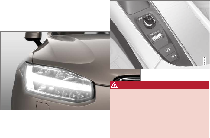
STARTING AND DRIVING
362
Battery drain
Your vehicle's electrical functions drain the bat-
tery to varying extents.
Avoid using ignition mode II as much as posssi-
ble, or electrical functions that require a great
deal of electrical current when the engine is not
running.
Using ignition mode I whenever possible con-
sumes less electrical current.
Functions that require a great deal of electrical
current include:
•the climate system blower
•headlights
•wipers
•infotainment system (especially at high vol-
ume).
If the battery's charge level is low, a text message
will appear in the instrument panel. The vehicle's
energy-saving function will then turn off or
reduce certain functions that are currently con-
suming electrical current.
If the battery needs to be recharged, start the
engine and let it idle for at least 15 minutes or
drive the vehicle (driving charges the battery
faster than letting the engine idle).
Related information
•Ignition modes (p. 360)
Starting the engine
The engine can be started using the start knob
on the tunnel console if there is a remote key in
the passenger compartment.
Start knob in the tunnel console between the front seats
WARNING
Before starting the engine:
•Fasten the seat belt.
•Check that the seat, steering wheel and
mirrors are adjusted properly.
•Make sure the brake pedal can be
depressed completely. Adjust the seat if
necessary.
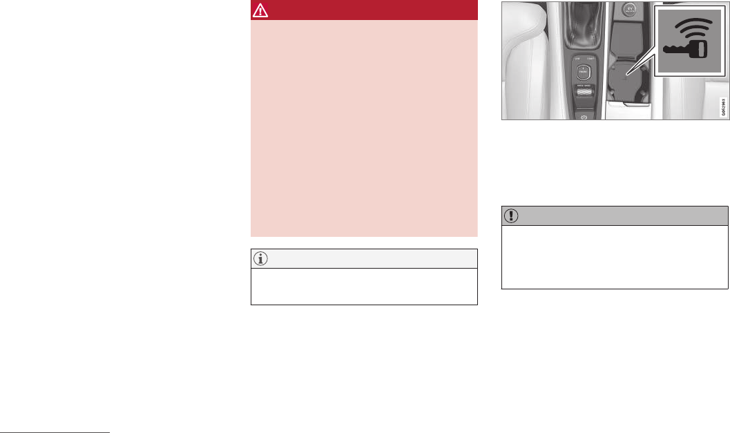
STARTING AND DRIVING
}}
363
To start the engine.
1. A remote key must be in the passenger com-
partment. On models with the standard
Passive Start, the key has to be in the front
section of the passenger compartment. If the
vehicle is equipped the optional Passive
Entry system (keyless locking/unlocking) the
key can be anywhere in the vehicle.
2. Press firmly on the brake pedal2.
3. Turn the start knob toward START and
release it to start the engine.
> The starter motor will crank until the
engine starts or its overheating protection
is triggered.
WARNING
•Never use more than one floor mat at a
time on the driver's floor. Before driving,
remove the original mat from the driver's
seat floor before using any other type of
floor mat. Any mat used in this position
should be securely and properly anchored
in the attaching pins. An extra mat on the
driver's floor can cause the accelerator
and/or brake pedal to catch. Check that
the movement of these pedals is not
impeded.
•Volvo's floor mats are specially manufac-
tured for your car. They must be firmly
secured in the clips on the floor so that
they cannot slide and become trapped
under the pedals on the driver's side.
NOTE
The vehicle cannot be started if the hybrid
battery is discharged.
Back-up reader in the tunnel console
If Vehicle key not found is displayed in the
instrument panel, place the remote key in the
back-up reader in the tunnel console (see the
illustration) and try again to start the engine.
CAUTION
If the engine does not start after the third try,
wait for approximately 3 minutes before trying
to start it again to give the battery time to
recover its starting capacity.
2If the vehicle is moving, it is only necessary to turn the start knob toward START to start the engine.
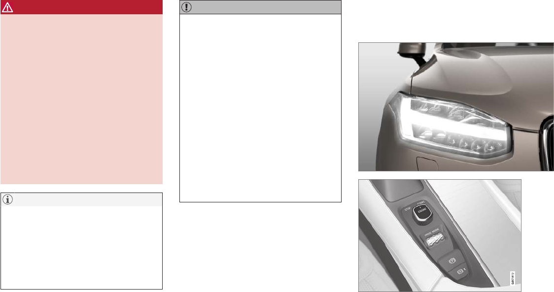
||
STARTING AND DRIVING
364
WARNING
•Always remove the remote key from the
passenger compartment when leaving the
vehicle and ensure that the ignition in
mode 0.
•On vehicles with the optional Passive
Entry, never remove the remote key from
the vehicle while it is being driven or
towed.
•Always place the gear selector in Park
and apply the parking brake before leav-
ing the vehicle. Never leave the vehicle
unattended with the engine running.
•Always open garage doors fully before
starting the engine inside a garage to
ensure adequate ventilation. The exhaust
gases contain carbon monoxide, which is
invisible and odorless but very poisonous.
NOTE
After a cold start, idle speed may be noticea-
bly higher than normal for a short period. This
is done to help bring components in the
emission control system to their normal oper-
ating temperature as quickly as possible,
which enables them to control emissions and
help reduce the vehicle's impact on the envi-
ronment.
CAUTION
•When starting in cold weather, the auto-
matic transmission may shift up at slightly
higher engine speeds than normal until
the automatic transmission fluid reaches
normal operating temperature.
•Do not race a cold engine immediately
after starting. Oil flow may not reach
some lubrication points fast enough to
prevent engine damage.
•The engine should be idling when you
move the gear selector. Never accelerate
until after you feel the transmission
engage. Accelerating immediately after
selecting a gear will cause harsh engage-
ment and premature transmission wear.
•Selecting P or N when idling at a stand-
still for prolonged periods of time will help
prevent overheating of the automatic
transmission fluid.
Related information
•Ignition modes (p. 360)
•Turning the engine off (p. 364)
•Changing the remote key's battery (p. 222)
•Jump starting (p. 355)
Turning the engine off
The engine can be turned off using the start
knob on the tunnel console.
Start knob in the tunnel console between the front seats

STARTING AND DRIVING
}}
* Option/accessory, for more information, see Introduction. 365
To turn off the engine:
–Turn the start knob toward STOP and
release it to switch the engine off.
If the gear selector is in P or if the vehicle is mov-
ing:
–Hold the knob in the STOP position until the
engine stops.
Related information
•Starting the engine (p. 362)
•Ignition modes (p. 360)
Drive modes*
Selecting a drive mode affects the vehicle's driv-
ing characteristics to help make driving more
enjoyable or easier in certain types of situations.
The following systems are adapted to help pro-
vide the best vehicle performance in the respec-
tive drive modes:
•Steering
•Engine/transmission/All Wheel Drive
•Brakes
•Suspension control
•Instrument panel
•Start/Stop
•Climate system settings
Select the drive mode best suited to the current
driving conditions.
Please be aware that not all modes can be
selected in all driving situations. The selected
mode will be displayed in the instrument panel.
Selecting a drive mode
1. Press the DRIVE MODE control in the tun-
nel console.
> A pop-up menu will open in the center
display.
2. Roll the control upward or downward to scroll
to the desired drive mode.
A drive mode can also be selected by tap-
ping its button on the center display.
3. Press the control again to select it.
When a driving mode cannot be selected, one of
the following messages may be displayed:
•Not possible to select due to gear in
manual
•Not possible to select due to low battery
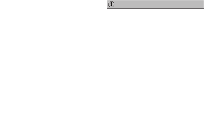
||
STARTING AND DRIVING
366
•Not possible to select due to low
temperature
•Not possible to select due to limitations
•Not possible to select due to high
speed.
Available drive modes
COMFORT
This is the default mode.
When the engine is started, COMFORT3 drive
mode will be selected and the Start/Stop func-
tion will be activated. This setting offers driving
comfort and light steering.
ECO
ECO drive mode is designed to help promote
fuel-efficient driving.
In this mode, Start/Stop is activated, ground
clearance is lowered to help reduce wind resis-
tance and certain climate system functions will
be reduced.
There is an ECO gauge in the instrument panel
to indicate the current level of fuel-efficiency. See
also the article "ECO drive mode."
OFF ROAD
This mode helps maximize the vehicle's capacity
to traverse difficult terrain or poor roads.
In OFF ROAD, ground clearance is maximized,
the steering is light, All Wheel Drive and Hill
Descent Control are activated and a compass
and altimeter will be displayed in the instrument
panel. Start/Stop is deactivated.
This drive mode can only be activated at low
speeds (the permissible speed range will be
shown on the speedometer). At higher speeds,
OFF ROAD mode will be cancelled and another
drive mode will be activated.
This mode is not intended for normal street driv-
ing.
CAUTION
OFF ROAD drive mode may not be used if
the vehicle is towing a trailer without an elec-
trical connection. This could result in damage
to the pneumatic suspension system's bel-
lows.
Due to the increased ground clearance, if the
OFF ROAD mode was selected when the engine
was switched off, it will also restart in this mode.
DYNAMIC
DYNAMIC driving mode is designed to provide
sportier driving characteristics.
Steering response will be more immediate, the
suspension will be stiffer and low ground clear-
ance will help reduce body roll when cornering.
Start/Stop will be deactivated.
INDIVIDUAL
This setting allows you to adapt a driving mode to
your personal preferences.
Select one of the other driving modes as a basis
and change the settings to provide the driving
characteristics that you prefer. This driving mode
is only available if it has been activated in the
center display.
INDIVIDUAL is only available if it has been acti-
vated in the center display.
3If the OFF ROAD mode was selected when the engine was switched off, it will also restart in this mode.
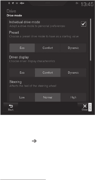
STARTING AND DRIVING
}}
* Option/accessory, for more information, see Introduction. 367
Settings view4 for INDIVIDUAL driving mode
1. Tap Settings in the center display's Top
view.
2. Tap My Car Individual Drive Mode and
tap Individual Drive Mode.
3. Select: Eco, Comfort or Dynamic.
The following settings can be modified:
•Driver Display
•Steering force
•Powertrain Characteristics
•Brake Characteristics
•Suspension Control
Related information
•Adjustable steering force* (p. 313)
•Loading (p. 205)
•Start/Stop (p. 370)
•ECO drive mode (p. 367)
•All Wheel Drive (AWD) (p. 378)
•Hill Descent Control (HDC) (p. 340)
•Brakes (p. 336)
ECO drive mode
The Eco drive mode is a function designed to
give the driver the opportunity to drive more eco-
nomically and to help reduce fuel consumption.
When this mode is activated, the following cha-
racteristics are modified:
•The automatic transmission's shifting points
•The engine management system and accel-
erator pedal response
•Eco Coast functionality is activated: engine
braking is disabled at speeds between
approx. 40 and 87 mph(65 and 140 km/h)
•Climate system settings: certain functions
will be temporarily reduced or deactivated
•The suspension's self-leveling function* low-
ers ground clearance to help reduce wind
resistance
•Information is shown in an ECO gauge in the
instrument panel to help promote more eco-
nomical driving
4Generic illustration.
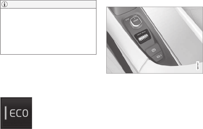
||
STARTING AND DRIVING
* Option/accessory, for more information, see Introduction.
368
NOTE
When Eco is activated, several climate system
parameters are changed and the function of
certain current-consuming systems will be
reduced.
Some of these functions can be restarted
manually but full functionality will not be
restored until Eco is deactivated.
Selecting ECO mode
When the engine is switched off, ECO mode is
deactivated and must be reactivated each time
the engine is started. ECO will appear in the
instrument panel when the function is activated.
Via Function view
Select Driving mode ECO in
the center display's Function
view. A green indicator light in
the button shows that the func-
tion is activated.
With the drive mode control*
1. Press the DRIVE MODE control.
> A pop-up menu will open in the center
display.
2. Roll the control upward or downward to scroll
to the desired drive mode and
3. Press the control again to select it. A drive
mode can also be selected by tapping its
button on the center display.
Eco Coast
Eco Coast essentially deactivates engine braking,
allowing the vehicle to roll freely.
When the driver releases the accelerator pedal,
the transmission is automatically disengaged
from the engine to allow the vehicle to roll as far
as possible, which helps reduce fuel consump-
tion.
This feature is primarily intended to be used in
driving situations where the vehicle can roll freely,
such as down gentle hills or when a decrease in
speed is expected, such as when approaching an
intersection or a traffic light.
Eco Coast enables proactive driving with as little
braking as possible.
Depending on the driving situation, Eco and Eco
Coast can be used in different ways to help
reduce fuel consumption:
•With Eco activated: this enables Eco Coast,
which allows the vehicle to roll freely for as
far as possible when the driver releases the
accelerator pedal (e.g., when approaching a
traffic light or intersection).
or
•With Eco deactivated: engine braking can
be used when the vehicle will only roll for
a short distance (in heavy traffic, etc.) or
when driving down hills.
To help keep fuel consumption as low as possi-
ble, Eco Coast should not be used in traffic situa-
tions where the brakes have to be used fre-
quently.
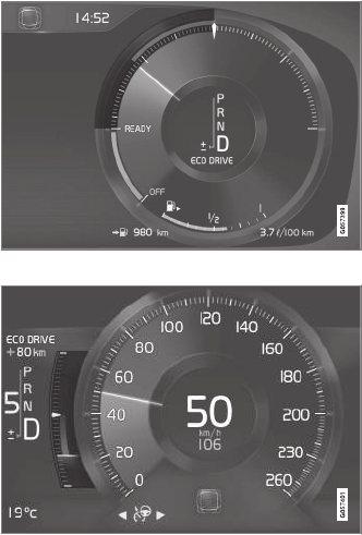
STARTING AND DRIVING
}}
* Option/accessory, for more information, see Introduction. 369
Activating Eco Coast
Eco Coast is activated when the accelerator
pedal is released completely if:
•Eco is activated
•The gear selector is in D
•The vehicle's speed is between approxi-
mately 40 and 87 mph(65 and 140 km/h)
Always observe posted speed limits
•The gradient of a down-slope is less than
approximately 6%
COASTING will appear in the instrument panel
when Eco Coast is being used.
Limitations
Eco Coast is not available if:
•The engine and/or transmission have not
reached their normal operating temperature
•Cruise control is activated
•The gear selector is moved from D to "+/-"
for manual shifting
•The vehicle's speed is not within the
40 and 87 mph(65 and 140 km/h) range
•The gradient of a down-slope is more than
approximately 6%
•The steering wheel paddles* are used for
manual shifting
Deactivating and turning off Eco Coast
In certain situations, it may be advisable to switch
off the Eco Coast function, such as:
•When driving down steep hills, in order to uti-
lize engine braking
•Prior to passing another vehicle, in order to
do so as safely as possible
Deactivating Eco Coast (and reactivating engine
braking) can be done in the following ways:
•Move the gear selector to the manual "+/–"
position
•Change gears using the steering wheel pad-
dles*
•Press the brake or accelerator pedal
Turn the function off by changing drive modes* or
by turning ECO off in the center display's Func-
tion view.
The vehicle will roll for short distances even if
Eco Coast is turned off to help conserve fuel.
However, for the best fuel economy, the function
should be used as much as possible.
ECO gauge in the instrument panel
Eco gauge 12" instrument panel
Eco gauge 8 instrument panel
The ECO gauge in the instrument panel helps
improve driving economy.

||
STARTING AND DRIVING
* Option/accessory, for more information, see Introduction.
370
•A low reading in the green area indicates
economical driving.
•A higher reading indicates higher fuel con-
sumption.
The ECO gauge also has an indicator showing
how a "reference" driver would drive in the same
situation. This is indicated by a diamond in the
gauge.
Related information
•Driving economically (p. 345)
•Drive modes* (p. 365)
•Start/Stop (p. 370)
Start/Stop
Start/Stop is a function that temporarily switches
off the engine when the vehicle is not moving,
for instance in heavy traffic or at a traffic light, to
help reduce fuel consumption. The engine starts
again automatically when the brake pedal is
released.
Start/Stop is one of several fuel-conserving fea-
tures that also help reduce emissions.
This feature helps make it possible to drive more
economically by allowing the engine to auto-stop
in certain situations.
Related information
•Conditions for Start/Stop (p. 372)
•Using the Start/Stop function (p. 370)
•ECO drive mode (p. 367)
Using the Start/Stop function
Start/Stop is a function that temporarily switches
off the engine when the vehicle is not moving,
for instance in heavy traffic or at a traffic light, to
help reduce fuel consumption. The engine starts
again automatically when the brake pedal is
released.
Start/Stop is available when the engine has been
started. The instrument panel will indicate if the
function is available/unavailable/active.
All of the vehicle's normal systems such as light-
ing, infotainment, etc., function normally when the
engine has auto-stopped. However, certain func-
tions, such as climate system blower speed or
very high infotainment system volume, will be
temporarily reduced.
Auto-stop
The following conditions must be met for the
engine to auto-stop:
•Stop the vehicle by applying the brakes and
keep the brake pedal depressed. The engine
will auto-stop. If the COMFORT6 or ECO driv-
ing modes are activated, the engine can
auto-stop before the vehicle has come to a
standstill.
If the Adaptive cruise or Pilot Assist functions
are activated, the engine will auto-stop after
approx. 3 seconds. See also the article "Condi-
tions for Start/Stop."
6The default driving mode.
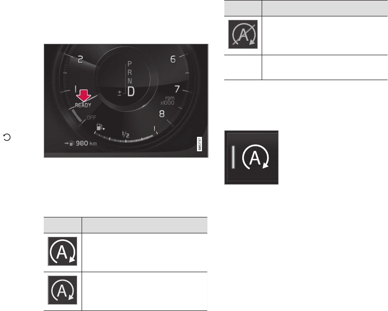
STARTING AND DRIVING
371
Auto-start
The following conditions must be met for the
engine to auto-start:
•Release the brake pedal; the engine will
automatically restart. When starting on an
uphill incline, the Hill Start Assist (HSA)
function will be activated to help prevent the
vehicle from rolling backward.
•When the brake system's Auto Hold function
is activated, the engine will not auto-start
until the accelerator pedal is pressed.
•When Adaptive cruise or Pilot Assist are
activated, the engine will auto-start when the
accelerator pedal is pressed or if the
button is pressed on the left-side steering
wheel keypad.
•Keep the brake pedal depressed but press
the accelerator pedal. The engine will auto-
start.
•On a downhill incline, release the brake pedal
so that the vehicle begins to roll. The engine
will auto-start after a slight increase in speed.
Symbols in the instrument panel
12" instrument panel
•READY will be displayed in the tachometer
when Start/Stop is available.
•An indicator in the tachometer will point
toward READY when Start/Stop is active
and the engine has auto-stopped.
•READY will be grayed-out when Start/Stop
is not available.
•No text will be displayed when Start/Stop is
turned off.
Instrument panel when Start/Stop is active and the
engine has auto-stopped
8" instrument panel
The symbol is displayed at the bottom of the
speedometer.
Symbol Explanation
White symbol: the function is avail-
able.
Beige symbol: the function is active
and the engine has auto-stopped.
Symbol Explanation
The function is not available
because the conditions have not
been met.
- No symbol displayed - the function
is turned off.
Turning Start/Stop off
In certain situations (e.g., heavy stop-and-go traf-
fic), it may be advisable to temporarily turn this
function off. To do so:
Tap the Start/Stop button in
the center display's Function
view. The green indicator light
in the button will go out. Start/
Stop will remain off until the
button is tapped again, the driv-
ing mode is changed
COMFORT or ECO, or until the engine is restar-
ted.
Related information
•Conditions for Start/Stop (p. 372)
•Start/Stop (p. 370)

STARTING AND DRIVING
* Option/accessory, for more information, see Introduction.
372
Conditions for Start/Stop
Certain conditions must be met for the Start/
Stop feature to function. If a condition is not met,
this will be indicated in the instrument panel.
The engine does not auto-stop
In certain situations or conditions, the engine
may not auto-stop when the vehicle comes to a
standstill, such as when:
•the vehicle has not reached a speed of
approx. 8 mph (12 km/h) after starting.
•after several auto-stops, the speed must
again exceed approx. 8 mph (12 km/h)
before the next auto-stop.
•the driver's seat belt is unbuckled.
•the main battery's charge is below the mini-
mum level.
•the engine has not reached its normal oper-
ating temperature.
•the ambient temperature is below approx.
23°F (-5°C) or above approx. 85°F (30°C).
•the windshield's heating function* is acti-
vated.
•the climate system cannot keep the desired
settings in the passenger compartment.
•the vehicle is backing up.
•the main battery's temperature is above or
below the permitted limits.
•the driver is turning the steering wheel hard.
•the road's incline is very steep.
•the hood is opened.
•the transmission has not reached its normal
operating temperature.
•driving at high altitude and the engine has
not reached its normal operating tempera-
ture.
•the gear selector is in the manual shifting
position.
•the ABS brakes have activated.
•hard braking (even if the ABS brakes have
not activated).
•many starts during a short time period have
triggered the starter motor's overheating pro-
tection.
•a trailer's electrical system is connected to
the vehicle's electrical system.
The engine does not auto-start
In certain situations or conditions, the engine
may not auto-start after an auto-stop, such as:
•if the driver is not wearing a seat belt
•the gear selector is in the P position and the
driver's door is open. The engine must be
started normally.
The engine auto-starts while the brake
pedal is depressed
In the following situations, the engine will auto-
start even though the brake pedal is depressed:
•condensation forms on the inside of the win-
dows.
•the climate system cannot keep the desired
settings in the passenger compartment.
•electrical current consumption is temporarily
high or the main battery's charge is below
the minimum level.
•the brake pedal is pumped repeatedly.
•the hood is opened.
•the vehicle begins to move or increases
speed slightly (if the engine auto-stopped
before the vehicle was at a standstill).
•the driver's seat belt is unbuckled while the
gear selector is in the D or N positions.
•the gear selector is moved from D to R or ±.
•the driver's door is opened with the gear
selector in D: an audible signal and a text
message will inform the driver that the igni-
tion is on.
WARNING
Do not open the hood if the engine has auto-
stopped. The engine could suddenly auto-
start.
Before opening the hood:
•Switch off the ignition by turning the start
knob in the tunnel console toward STOP.
•Be aware that if the engine has been run-
ning, components in the engine compart-
ment will be very hot.
STARTING AND DRIVING
* Option/accessory, for more information, see Introduction. 373
Related information
•Using the Start/Stop function (p. 370)
Automatic transmission
The automatic transmission has 8 forward gears
and shifts up or down based on the level of
acceleration, speed and engine speed (meas-
ured in revolutions per minute - rpm). Manual
shifting is also possible. The gear indicator in the
instrument panel shows the gear currently being
used or gear shift mode.
CAUTION
The transmission’s temperature is monitored
to help prevent damage to the transmission
or other drivetrain components. If there is a
risk of overheating, the warning symbol on the
instrument panel will illuminate and a text
message will be displayed. Follow the instruc-
tions provided there.
Symbols in the instrument panel
If a problem should occur with the transmission, a
symbol and a message will be displayed in the
instrument panel.
Symbol Explanation
Transmission-related information.
Follow the instructions provided.
Hot or overheated transmission.
Follow the instructions provided.
Related information
•Gear selector positions (p. 375)
•Gear shift indicator (p. 375)
•Shiftlock (p. 374)
•Steering wheel paddles* (p. 377)
•All Wheel Drive (AWD) (p. 378)
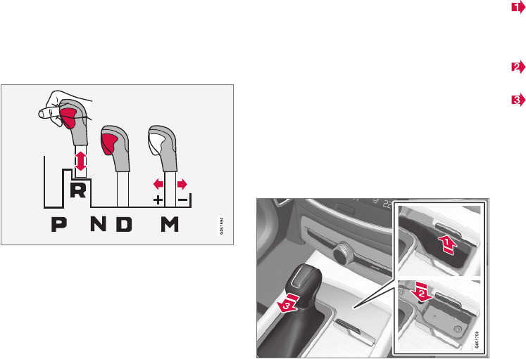
STARTING AND DRIVING
374
Shiftlock
The automatic transmission's shiftlock feature
helps prevent inadvertently moving the gear
selector between different positions.
There are two different types of shiftlock:
mechanical and automatic.
Mechanical shiftlock
The gear selector can be moved back and forth
freely between N and D. There is a mechanical
shiftlock for the other positions.
To move the gear selector to between P, R, N
and D, press the button on the front of the gear
selector (see the illustration).
Automatic shiftlock
From Park – P
In order to move the gear selector from the P
position, the brake pedal must be depressed and
the ignition must be in mode II.
From neutral – N
If the gear selector is in N and the vehicle has
been stationary for more than 3 seconds (regard-
less of whether or not the engine is running), the
shiftlock feature will lock the gear selector in this
position.
In order to move the gear selector from the N
position, the brake pedal must be depressed and
the ignition must be in mode II.
Shiftlock override
If the vehicle cannot be driven (e.g., due to a dis-
charged battery), the shiftlock feature has to be
overridden in order to move the gear selector
from the P or D positions into N so that the vehi-
cle can be moved. To do so:
Lift away the rubber mat on the bottom of
the storage compartment in front of the gear
selector to expose the small hole for overrid-
ing the shiftlock feature.
Press a small screwdriver or similar item into
the hole and hold it down.
Press the button on the front side of the
gear selector and move the selector to the N
position. Release the button and remove the
screwdriver from the hole.
4. Put the rubber mat back into place.
Related information
•Gear selector positions (p. 375)
•Automatic transmission (p. 373)
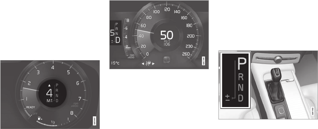
STARTING AND DRIVING
}}
* Option/accessory, for more information, see Introduction. 375
Gear shift indicator
The gear shift indicator in the instrument panel
shows the current gear (in manual shifting
mode) and will prompt the driver to shift up or
down to help get the best possible fuel econ-
omy.
The gear shift indicator shows the current gear in
the instrument panel and uses an upward arrow
to recommend shifting to a higher gear.
Gear shift indicator (generic illustration)
Gear shift indicator (generic illustration)
Related information
•Gear selector positions (p. 375)
•Steering wheel paddles* (p. 377)
Gear selector positions
The transmission automatically shifts between
the various forward gears, based on the level of
acceleration and speed.
The automatic transmission has 8 forward gears
and also offers manual shifting.
Gear selector positions
The following gear selector positions are shown
in the instrument panel:
P, R, N, D or M.
For manual shifting, the gear indicator in the
instrument panel shows the gear currently being
used (1–8).
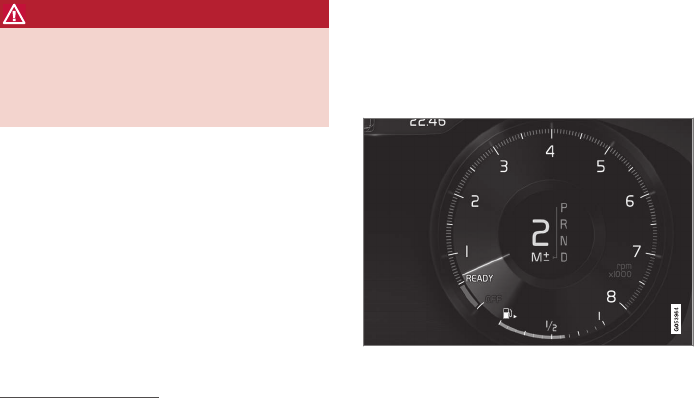
||
STARTING AND DRIVING
* Option/accessory, for more information, see Introduction.
376
Park – P
Select P when the vehicle is parked or when the
starting the engine. The vehicle must be station-
ary when P is selected.
The ignition must be in mode II and the brake
pedal must be depressed before the gear selec-
tor can be moved from P.
In position P, the transmission is mechanically
locked. Always apply the parking brake when the
vehicle is parked.
WARNING
Always apply the parking brake when the
vehicle is parked, particularly when parking on
a hill. The transmission's P mode may not be
able to keep the vehicle stationary if it is
parked on an incline.
Reverse – R
The vehicle must be stationary before R can be
selected.
Neutral – N
No gear is selected and the engine can be
started. Always apply the parking brake if the
vehicle is not moving and the gear selector is in
the N position.
The ignition must be in mode II and the brake
pedal must be depressed before the gear selec-
tor can be moved from N.
Drive – D
D is the normal driving position and gear shifting
is fully automatic. The vehicle must be stationary
when the gear selector is moved from R to D.
Manual shifting – M (shown on the
instrument panel)
Manual shifting can be selected at any time and
engine braking will occur when the accelerator
pedal is released.
To select, move the gear selector from D to the
side toward "±". The current gear (1 - 8) will be
shown in the instrument panel.
•Press the gear selector forward toward "+"
(plus) and release it to shift up one gear.
•Pull the gear selector rearward toward "–"
(minus) and release it to shift down one gear.
Manual shift indicator in the instrument panel8.
For smooth shifting and engine performance, the
transmission will shift down automatically if the
vehicle's speed becomes too low for the selected
gear.
Move the gear selector to the side toward D at
any time to resume automatic gear shifting.
Safety function
To help avoid excessive rpm that might cause
engine damage, the transmission control module
has a down-shift protection feature that in some
situations may prevent a down-shift or kickdown.
During kickdown, the transmission may shift
down one or more gears, depending on the
engine's rpm and will shift up again when max.
rpm is reached for a specific gear.
Related information
•Steering wheel paddles* (p. 377)
•Shiftlock (p. 374)
•Gear shift indicator (p. 375)
8Generic illustration.
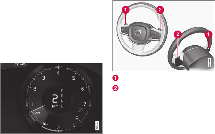
STARTING AND DRIVING
* Option/accessory, for more information, see Introduction. 377
Steering wheel paddles*
In addition to the manual gearshift function using
the gear selector, the paddles make it possible
to manually shift gears from the steering wheel.
Activating the paddles
In order to shift gears with the paddles, they have
to first be activated. To do so:
–Pull either paddle toward the steering wheel
and release it; the D in the instrument panel
will change to M and the number of the gear
currently being used will be displayed.
Manually shifting gears
In shift mode M, the paddles are automatically
activated.
Shifting
To shift one gear:
–Pull either paddle toward the steering wheel
and release it.
"–": Shift down one gear.
"+": Shift up one gear.
A gear shift will take place each time a paddle is
pulled if the engine speed (rpm) is within the per-
missible range for the selected gear.
The gear number shown in the instrument panel
will change after each gear shift.
Deactivating the paddles
Manually
–Pull both paddles toward the steering wheel
and hold them until the number of the cur-
rent gear is no longer displayed in the instru-
ment panel.
Automatically
If the paddles are not used for a period of time,
they will deactivate automatically. The number of
the current gear in the instrument panel changes
to "D".
The paddles will remain active if engine braking is
currently being used.
Related information
•Gear selector positions (p. 375)
•Gear shift indicator (p. 375)
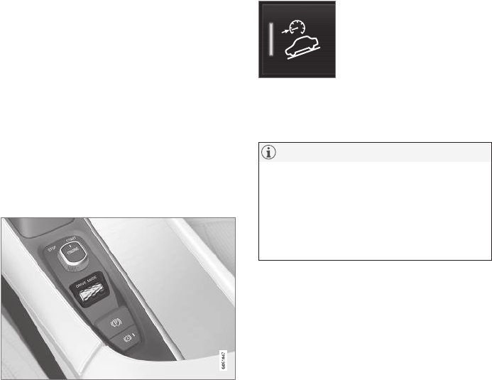
STARTING AND DRIVING
* Option/accessory, for more information, see Introduction.
378
Low Speed Control (LSC)
Low Speed Control (LSC) helps make off-road
driving easier on slippery surfaces when towing
a trailer on grass, etc. This feature is part of the
Off Road drive mode.
When driving at low speeds, LSC prioritizes low
gears and all wheel drive to help avoid wheel spin
and to improve the vehicle's tractive force. The
accelerator pedal and engine react differently to
make low-speed driving easier.
It is activated along with Hill Descent Control
(HDC), which increases engine braking to help
keep vehicle speed low and smooth, even driving
down steep hills.
Activating LSC
This function can be activated in different ways,
depending on how the vehicle is equipped.
Using the drive mode control*
Select the Off Road drive mode to activate the
function.
Select any other drive mode to turn it off.
From the center display's Function view
Models without the drive mode
control have a button for Hill
Descent Control in the center
display's Function view.
•Tap the button to activate. A light in the but-
ton illuminates when the function is acti-
vated.
NOTE
When LSC with HDC is activated, the feel of
the accelerator pedal and engine response
will change.
The function is deactivated when driving at
higher speeds and must be reactivated at
lower speeds if so desired.
Related information
•Brake functions (p. 338)
•Hill Descent Control (HDC) (p. 340)
•Drive modes* (p. 365)
All Wheel Drive (AWD)9
Your Volvo can be equipped with All Wheel
Drive, which means that power is distributed
automatically between the front and rear wheels.
Under normal driving conditions, most of the
engine's power is directed to the front wheels.
However, if there is any tendency for the front
wheels to spin, an electronically controlled cou-
pling distributes power to the wheels that have
the best traction.
AWD reacts differently, depending on the drive
mode* selected.
Related information
•Drive modes* (p. 365)
•Low Speed Control (LSC) (p. 378)

STARTING AND DRIVING
* Option/accessory, for more information, see Introduction. 379
Suspension and leveling control*
The leveling control system adjusts the suspen-
sion and shock absorbers automatically to help
provide good comfort and control while driving.
Leveling can also be controlled manually to
make loading or getting in and out of the vehicle
easier.
Pneumatic suspension and shock
absorbers
This system is linked to the selected drive mode
and is adapted to the vehicle's speed. The pneu-
matic suspension reduces the vehicle's ground
clearance at higher speeds to reduce wind resis-
tance and increase stability. The shock absorbers
are normally set to provide the best possible
comfort and are adjusted continuously according
to the road surface, acceleration, braking and
cornering.
A message will be displayed in the instrument
panel when the suspension level is being
adjusted.
The level cannot be adjusted if one of the side
doors or the hood is open.
Suspension leveling settings
Easy entry
The vehicle can be lowered to entering and exit-
ing easier.
Select Settings Vehicle Easy Entry/Exit
Control via the center display's Top view to lower
the vehicle when getting in or out.
When the vehicle is parked and the engine is
turned off, the level is lowered (if a side door is
opened, the level adjustment will stop). When the
engine is started and the vehicle begins to move,
the level will be raised to the height set by the
selected drive mode.
Turning off suspension and leveling control
In certain situations, this function has to be
turned off, for example when lifting the vehicle on
a jack or garage hoist.
1. Tap Settings in the center display's Top
view.
2. Tap My Car Suspension .
3. Select Deactivate Suspension & Leveling
Control.
Changing suspension control
Three different levels of suspension control can
be selected from the center display:
1. Tap Settings in the center display's Top
view.
2. Tap My Car Drive Mode.
3. Under Suspension Control, select Eco,
Comfort or Dynamic.
Loading mode
Use the buttons in the cargo compartment to
raise or lower the vehicle to make loading or
unloading easier or when attaching a trailer.
Parking the vehicle
When parking, be sure that there is adequate
space above and below the vehicle since its
ground clearance may vary, e.g., depending on
the ambient temperature, how the vehicle is loa-
ded, if loading mode is being used or the drive
mode selected after the engine is started.
The level may also be adjusted for a certain time
after the vehicle has been parked to compensate
for possible height adjustments due to tempera-
ture changes in the pneumatic suspension when
the vehicle has cooled.
Transport
When transporting the vehicle on a ferry, train or
a tow truck, it may only be secured (lashed)
around the tires, not using any other chassis
components. Changes in the pneumatic suspen-
sion may occur during transport that could nega-
tively affect the lashing and result in damage.
Related information
•Drive modes* (p. 365)
•Driving with a trailer (p. 357)
•Loading (p. 205)
9Standard equipment on certain models.


INFOTAINMENT
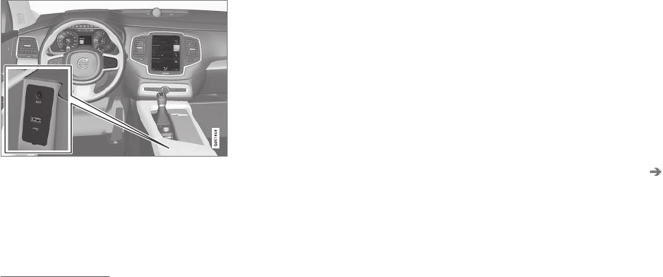
INFOTAINMENT
382
The infotainment system
The infotainment system consists of a radio,
media player and has the capacity to communi-
cate with a Bluetooth-connected cell phone. It is
also possible to connect to the Internet to e.g.,
stream audio content via apps.
The system's functions can be controlled from
the right-side steering wheel keypad, the center
display or by using voice commands.
Infotainment overview
System updates
The infotainment system is constantly being
developed and improved. For optimal functional-
ity, updates can be downloaded. See the article
"System updates" and the support site
support.volvocars.com.
Related information
•Media player (p. 399)
•Radio (p. 383)
•Phone (p. 393)
•Internet connected vehicle (p. 409)
•Apps (applications) (p. 411)
•Ignition modes (p. 360)
•Symbols in the center display status bar
(p. 43)
•Voice control (p. 116)
•Infotainment system license information
(p. 416)
•System updates (p. 498)
Sound settings
The infotainment system is precalibrated for opti-
mal sound reproduction but these settings can
be changed to suit your personal preferences.
The system's volume is normally adjusted using
the right-side steering wheel keypad or the vol-
ume control below the center display.
Optimal sound reproduction settings
The audio system is precalibrated for optimal
sound reproduction using digital signal process-
ing. This calibration takes into account the speak-
ers, amplifier, cabin acoustics, listener position,
etc., for each combination of vehicle and infotain-
ment system.
Dynamic calibration is also available, which moni-
tors the setting of the volume control, radio
reception and the vehicle's speed.
Specific sound settings are described in the
respective articles/sections of this owner's infor-
mation.
To change a setting, pull down the center dis-
play's Top view and tap Settings Sound.
Active noise suppression1
The vehicle can be equipped with an active noise
suppression function that reduces engine noise
in the passenger compartment by utilizing the
infotainment system. The microphone(s) in the
1Certain models only.
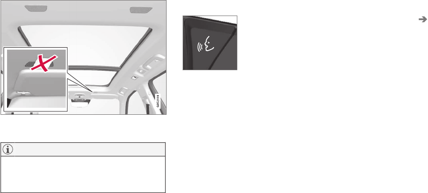
INFOTAINMENT
}}
* Option/accessory, for more information, see Introduction. 383
ceiling liner react to engine noise and the info-
tainment system produces signals (white noise)
to counteract this.
Microphone in the ceiling liner. The number and position
vary, depending on the vehicle
NOTE
Avoid covering or obstructing the noise sup-
pression speakers because doing so could
result in a rumbling noise.
Related information
•Media sound settings (p. 406)
•Voice control settings (p. 121)
•Phone settings (p. 398)
Radio
Your vehicle's radio offers AM and FM with HD
Radio ™ Technology and SiriusXM® Satellite
radio*.
The radio can be controlled
using the right-side steering
wheel keypad, the center dis-
play or by using voice com-
mands.
Related information
•Changing and searching for radio stations
(p. 384)
•Radio settings (p. 383)
•SiriusXM® Satellite radio* (p. 389)
•HD Radio™reception (p. 386)
•Changing and searching for radio stations
(p. 384)
Radio settings
The following information lists the settings that
can be made for the various wavebands.
Pull down the center display's Top view and
select Settings Media for the desired wave-
band. Tap to activate/deactivate.
AM/FM
•Show Radio Text: displays information
about program content, artists, etc.
•Freeze Program Service Name: select to
stop excessive scrolling to freeze after
20 seconds.
•AM HD Radio: Enables HD Radio ™
Technology for AM audio quality comparable
to analogue FM.
•FM HD Radio: - Enables HD Radio ™
Technology for audio comparable to CD
quality. See the article "HD Radio" for
detailed information.
SiriusXM® Satellite radio
With SiriusXM® Satellite radio activated, pull
down the center display's Top view and tap
SiriusXM Settings to display a list of available
alternatives. See the article "SiriusXM Satellite
radio settings" for detailed information.
Related information
•SiriusXM® Satellite radio* settings (p. 391)
•SiriusXM® Satellite radio* (p. 389)

INFOTAINMENT
384
•Radio (p. 383)
•HD Radio™reception (p. 386)
RBDS radio
RBDS radio
RBDS (Radio Data Broadcast System) enables
certain functionality2, such as:
•Searches for program types or new broad-
casts
•Text information about currently broadcast
programs
For example, if news is broadcast, the currently
playing sound source will be interrupted so that
the news can be heard. The infotainment system
will return to the previous sound source when the
news broadcast has been completed.
To cancel the announcement, press the but-
ton on the right-side steering wheel keypad or
tap Cancel on the center display. This function
can be activated/deactivated in the center dis-
play's Settings menu.
Related information
•Radio (p. 383)
•Radio settings (p. 383)
Changing and searching for radio
stations
The radio automatically compiles a list of the
strongest stations that it is currently receiving.
Turning the radio on
1. Open the app (e.g., FM, radio favorites) from
the center display's App view.
2. Select a station.
Changing a list in a waveband
1. Tap Library.
2. Sect from Stations, Favorites or Genres.
3. Tap the desired station in the list.
Favorites: only plays stations from the list of
favorites (see "Favorites" below).
Genres: only plays stations broadcasting the
selected genre or program type, e.g., pop, classi-
cal, etc.
Changing stations in a selected list
–Tap < > under the center display or on the
right-side steering wheel keypad.
> Move step-by-step through the selected
list.
The center display can also be used to change
stations.
2Certain stations only.
INFOTAINMENT
* Option/accessory, for more information, see Introduction. 385
Favorites
If a favorite station from a list is currently availa-
ble, the radio will automatically tune to that sta-
tion.
See "Changing a list in a waveband" above for
information about selecting favorites on a wave-
band. See "Radio favorites" below for information
about selecting a station among all of your favor-
ites.
–Tap to add or remove a station for the
waveband's list of favorites or Radio favorites.
Radio favorites
Radio favorites shows all of the
favorite stations that have been
saved for e.g., AM, FM.
1. Open the Radio favorites app in App view.
2. Tap the desired station to listen.
When a station is removed, it will also be
removed from the respective waveband's list of
favorites.
Changing wavebands3
–Tap an app, e.g., FM in App view or open the
app menu from the right-side steering wheel
keypad to select.
Searching for a radio station
Searching is done differently, depending on the
waveband selected.
•AM: stations and frequencies.
•FM: stations, genres and frequencies.
•SiriusXM®: program types, genres, stations.
1. Tap Library.
2. Tap .
> The search view with a keyboard will open.
3. Enter a search word(s).
> The search will start and change as char-
acters are entered and the search results
will be categorized.
Searching for a station manually
Searching manually makes it possible to find and
tune to stations that are not on the automatically
compiled list of the strongest stations in the area.
–Tap Manual tuning, drag the control or tap
< > to go to the desired frequency.
Related information
•SiriusXM® Satellite radio* (p. 389)
•HD Radio™reception (p. 386)
3The AM waveband is not available in hybrid models.
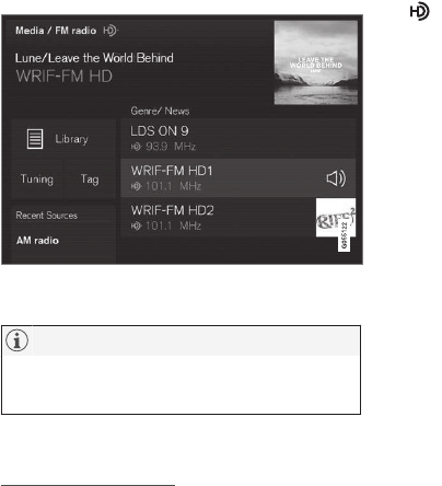
INFOTAINMENT
* Option/accessory, for more information, see Introduction.
386
HD Radio™reception
HD Radio is a brand name registered by the
iBiquity digital corporation4. They are the devel-
oper of a broadcasting technology called IBOC
or In Band On Channel, which refers to the
method of transmitting a digital radio broadcast
signal centered on the same frequency as the
AM or FM station's present frequency.
Introduction
Display when the radio is receiving an HD Radio broad-
cast (generic illustration)
NOTE
HD Radio volume may fade in and out at
times due to coverage limitations.
The IBOC system is referred to as a "hybrid"
since it is both analogue and digital. During
hybrid operation, receivers still continue to
receive the analogue (non-digital) signal. HD
Radio receivers incorporate both modes of
reception, where the receiver will automatically
switch to the analogue signal if the digital signal
cannot be decoded or is lost by the receiver.
When you have tuned to an HD Radio station, the
symbol will appear in the infotainment sys-
tem display. The symbol will be displayed in dif-
ferent colors:
•Grayed-out symbol: NoHD Radio broadcast
reception
•White symbol: the radio is actively receiving
an HD broadcast
•Orange symbol: the radio is receiving an
HD broadcast with digital sound
More information about HD Radio and IBOC can
be found on Ibiquity's website, www.hdradio.com
and www.ibiquity.com.
Artist Experience™
A radio station's logo and album art can be dis-
played. If a station opts to provide this informa-
tion, it is broadcast once every 12 minutes, which
means that there may be a delay before the
logo/album art appear on the screen. The radio
can store 100 station logos so the next time the
radio is tuned to the same station, the logo will
be displayed immediately. Album art is synched
with the artist that you are currently listening to.
iTunes tagging
This feature is common to both HD Radio and
SiriusXM® Satellite radio*. See the section
"iTunes tagging" in the article "SiriusXM satellite
radio settings" for more detailed information.
Ball game mode
This feature means that a main FM station (HD1)
will broadcast live events, where the content of
the programming is more important than sound
quality, in analog mode only to help prevent the
delay between analog and digital broadcasting.
The HD Radio symbol will be white during live
broadcasts and "Live" will be displayed next to
the symbol.
Benefits of digital broadcasting
•Better sound (FM sounds near CD quality
and AM as analogue FM).
•Some FM frequencies offer a greater num-
ber of listening choices through “multicast-
ing” (consisting of a frequency's main chan-
nel and any sub-channels that may also be
available on that particular frequency.)
•When receiving a digital signal there is no
multipath disturbance or hisses/pops/crack-
ling due to outside influences.
4HD Radio (TM) technology is manufactured under license from iBiquity Digital Corp. U.S. and Foreign Patents. HD Radio(TM) and the HD and HD Radio logos are proprietary trademarks of iBiquity Digital Corp.
INFOTAINMENT
* Option/accessory, for more information, see Introduction. 387
How HD Radio ™ Technology
broadcasting works
HD Radio works similarly to conventional radio
and broadcasts of this type are available in many
areas of the United States. However, there are a
few key differences:
•Instead of transmitting one analogue signal,
stations send out a bundled signal – both
analogue and digital.
•An HD Radio receiver can receive both digi-
tal and analogue broadcasts. Depending on
the terrain and location of the vehicle (which
will influence the signal strength), the
receiver will determine which signal to
receive.
Related information
•Switching HD Radio on and off (p. 387)
•HD Radio sub-channels (p. 388)
•HD Radio limitations (p. 388)
•Radio (p. 383)
•Changing and searching for radio stations
(p. 384)
Switching HD Radio on and off
The factory setting for HD Radio is off.
Switching HD on or off
When listening to an HD Radio station and driv-
ing through areas with weak HD signals (fringe
areas), you may experience that the radio repeat-
edly switches between analogue/digital and digi-
tal/analogue reception. If this happens, it may be
desirable to switch HD off.
To do so:
1. Be sure the infotainment system is switched
on and in AM or FM mode.
2. To access the settings menu from the center
display's Home view, pull down Top view and
tap AM/FM Radio.
Go to Adjust settings for media.
3. Tap the AM HD Radio or FM HD Radio box
to select/deselect this function.
This will disable the radio's capability to receive
digital broadcasts but it will continue to function
as a conventional (analogue) AM/FM receiver.
Please note that when HD is switched off, it will
not be possible to tune to sub-channels (see the
article "HD Radio subchannels" for a more
detailed explanation of sub-channels).
Please note that this will only switch HD Radio
on or off (selecting or deselecting the function)
only affects the selected waveband.
Related information
•HD Radio™reception (p. 386)
•HD Radio sub-channels (p. 388)
•SiriusXM® Satellite radio* settings (p. 391)
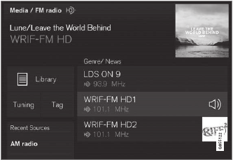
INFOTAINMENT
388
HD Radio sub-channels
In many cases, a main HD Radio station (FM
wavebands only) will also have sub-channels
offering additional types of programming or
music.
Sub-channels
Example of an HD Radio station with sub-channels
If any sub-channels are available, they will listed
below the main channel on the screen. In this
example, "WRIF-FM HD2" is a sub-channel.
Selecting sub-channels
To listen to a station's sub-channel(s), tap the
station on the screen or press the forward/back
arrow keys on the right-side steering wheel key-
pad or below the screen.
Sub-channels can also be stored as favorites, see
the article "Changing and searching for radio sta-
tions".
If you tap a sub-channel favorite, it may take up
to 6 seconds before the channel becomes audi-
ble. If you tap a station while you are out of digital
range of the transmitter, No reception will be
displayed.
Related information
•HD Radio™reception (p. 386)
•Switching HD Radio on and off (p. 387)
•Changing and searching for radio stations
(p. 384)
HD Radio limitations
Limitations
•Main channel vs. sub-channels (FM only):
The main channel is the only channel that
can receive in hybrid mode (both digital and
analogue). If a frequency has sub-channels,
they are broadcast in digital mode only. The
main FM channel will be displayed as, for
example, "WRIF-FM HD1". The sub-FM
channels will be displayed as"WRIF-FM
HD2", "WRIF-FM HD3", etc.
•Reception coverage area: Due to current
IBOC transmitter power limitations, the
reception coverage area in digital mode is
somewhat more limited than the station's
analogue coverage area. Please be aware
that as with any radio broadcast technology,
terrain, time of day, foliage level and building
location can have positive or negative effects
on radio reception.
•Analogue to digital/digital to analogue
blending: Analogue to digital blending will
occur as the signal strength reaches a preset
threshold in the receiver. This will be noticea-
ble in fringe areas (areas with weak recep-
tion) and is normal.
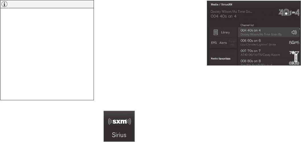
INFOTAINMENT
}}
* Option/accessory, for more information, see Introduction. 389
NOTE
There may be a noticeable difference in
sound quality when a change from analogue
to digital or digital to analogue occurs, such
as:
•Volume increase or decrease
•Equalizer settings, i.e., Bass/ Midrange/
Treble cut or boost
•Time alignment (Digital program material
in extreme cases can be as much as 8
seconds behind the analogue). This will
noticeable as a "stuttering" effect.
The above items are dependant on the
broadcaster's equipment settings and do
not indicate a fault in the vehicle's radio
receiver or antenna systems.
Related information
•HD Radio sub-channels (p. 388)
•HD Radio™reception (p. 386)
SiriusXM® Satellite radio*
The SiriusXM® Satellite system broadcasts from
of a number of high elevation satellites in geo-
synchronous orbit.
Listening to satellite radio
The digital signals from the satellites are line-of-
sight, which means that physical obstructions
such as bridges, tunnels, etc, may temporarily
interfere with signal reception.
Avoid any obstructions, such as metallic objects
transported on roof racks or in a ski box, or other
antennas that may impede signals from the
SiriusXM® satellites.
Selecting SiriusXM® Satellite radio
mode
1. From the center display's Home view, swipe
from right to left to come to App view.
2. Tap the SiriusXM® Satellite radio icon.
Home view with SiriusXM® Satellite radio activated
If there is no subscription activated, tap channel
1, where you will be prompted on the screen to
phone SiriusXM®.
If a cell phone is paired and connected to the
vehicle, you can also subscribe by:
1. From Home view, pull down the Settings
menu.
2. Open the settings menu for SiriusXM® Satel-
lite radio.
3. Tap Unsubscribed Services
4. Tap the phone number to call SiriusXM®,
who will activate the subscription of your
choice. This may take several minutes.
When the subscription has been activated, tap
the SiriusXM® Satellite radio icon to start the
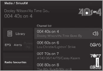
||
INFOTAINMENT
* Option/accessory, for more information, see Introduction.
390
function and display the channel list included in
your subscription.
Related information
•Using SiriusXM® Satellite radio radio*
(p. 390)
Using SiriusXM® Satellite radio
radio*
SiriusXM® Satellite radio offers several features
for finding and listening to music, news, sporting
events, etc. being broadcast on satellite radio
stations.
SiriusXM® Satellite radio functions
With SiriusXM® Satellite radio activated, tap
Library to display a screen offering the following
functions:
•Search (the magnifying glass icon)
•Channels
•Favorites
•Categories
If you have used this view previously, you will be
returned to the most recently used one.
Search
Tap the magnifying glass to display a screen
where you can enter text using the center dis-
play's keyboard or by writing in the free-text field
to search for e.g., a station number, an artist,
song title, etc.
Channels
Tap to display a complete list of the channels
included in your subscription. Tap a channel
name to listen. If a subscription to a channel has
expired, its name will be grayed-out on the
screen.
For quick access to a channel that you often lis-
ten to, tap the star to the right of the channel's
name to add it to the list of favorites.
Favorites
Tap to display the channels that you have added
to this list. Tap a channel name to listen.
Categories/Genres
Tap to display the categories available. Tap a cat-
egory or genre name to display the channels that
it contains and then tap a channel to listen.
If an alert has been set (see the section "Alerts"
below) and an alert is active for an artist, song or
team, virtual categories will also be temporary
created and displayed. The channels currently
broadcasting the song, artist or broadcasting a
program with the selected team will be listed in a
virtual category.
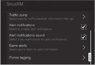
INFOTAINMENT
}}
* Option/accessory, for more information, see Introduction. 391
EPG (Electronic Program Guide)
On the center display's Home screen, tap EPG
for information about e.g., when a program is
being broadcast and its name, description, artist,
etc. If no information is currently available, No
information will be displayed.
Alerts
If this feature has been selected under SiriusXM
Settings, the Alerts button will be displayed on
the Home screen.
To add e.g., an artist's name, song title or a sports
team to the list of alerts:
1. Tune to any channel that is broadcasting a
song, game, etc., of your choice.
2. Press the Alerts button.
3. A pop-up window will be displayed showing a
list of alerts (nothing will be displayed if the
selected channel does not support the alert
function).
4. Select one of the alternatives in list (only one
can be selected at a time).
5. The song/artist/team will now be added to
the list of alerts. Favorite sports teams can
also be added to the list using the "Game
Alert" setting as described in the article "Sir-
iusXM satellite radio settings."
> When your choice is being broadcast on a
channel, you will be informed by a pop-up.
iTunes tagging
From the center display's Top view, tapSiriusXM
Settings. Tap theiTunes Tagging menu. Tap
the iTunes Tagging box to activate/deactivate
this function and tap Close to return to Home
view. Tap List Of Tags to display a list of all tag-
ged songs.
If the function is activated, the iTunes tag button
will be displayed in Home view. If a song is played
that you would like to buy in the iTunes store, tap
this button while the song is playing to tag it. If a
song with iTunes Tagging information is availa-
ble, the button will be selectable. Tap the button
to tag the song. If you would like to buy a tagged
song via iTunes, Tap the iTunes tag button.
To buy a song in iTunes, begin by connecting an
iPhone/iPod/iPad to the USB socket in the tun-
nel console. The iTunes tagging list will automati-
cally be transferred to the device and removed
from the list in the vehicle. If the device is con-
nected when a song is tagged, the data will auto-
matically be saved in the device. To purchase the
song, consult the iTunes support page.
Related information
•SiriusXM® Satellite radio* (p. 389)
•Using the center display keyboard (p. 31)
•SiriusXM® Satellite radio* settings (p. 391)
•Connecting a device via the AUX/USB
socket (p. 399)
SiriusXM® Satellite radio* settings
There are numerous settings that can be made
to enhance your SiriusXM® Satellite radio listen-
ing experience.
Settings
To access the settings menu from the center dis-
play's Home view, pull down Top view and tap
SiriusXM Settings. The following alternatives
will be displayed:
||
INFOTAINMENT
* Option/accessory, for more information, see Introduction.
392
Traffic Jump
Tap to display a list of cities from which you can
choose to get traffic/weather information (or
Traffic jump off to deactivate the feature). Tap
to select a city (JUMP will be displayed on the
Home screen next to Library). Tap Back to
return to the list of settings or Close to return to
the Home screen.
From the Home screen, tap JUMP to activate the
function. When traffic/weather information is
available from the selected city, the radio will
automatically tune to the channel providing the
information. When the information/announce-
ment is finished, the radio will automatically
return to the channel that you were previously lis-
tening to.
During an announcement, tap JUMP to interrupt
the message and return to the station that you
were currently listening to.
Alert notifications
Tap the box to activate/deactivate. When acti-
vated, you will be notified if a song, artist, etc. that
you have selected is playing. You will be asked if
you want to listen.
Alert notifications sound
Opt to receive an audible alert when one of your
selected choices is being played.
iTunes tagging
Tap to display a menu with the options: iTunes
Tagging and List Of Tags. With this feature
activated, songs can be tagged for later purchase
from the iTunes store.
Game Alerts
Tap to display a list of sports.
Tap a sport to display a list of teams and tap a
box on the right side of the screen to select a
team as a favorite. An alert will then be provided
when information about the team is being broad-
cast.
Tap Confirm below the list to return to the list of
sports.
Tap Back to return to the list of settings or
Close to return to the main screen.
Unsubscribed services
If you have a SiriusXM® Satellite radio subscrip-
tion, any channels not included in the subscrip-
tion will be listed here. Call SiriusXM™ to sub-
scribe. The phone number will be shown on the
screen. If a cell phone is paired and connected to
the vehicle, tap the phone number to make the
call.
Skipped stations
Tap to display a list of channels that you would
like to skip (hide). Hide channels from the chan-
nel list by tapping the boxes to the right of the
screen. Skipped (hidden) channels will not be
shown in the channel list. However, a channel
previously selected as a favorite will still be dis-
played in the list of favorites, even it has been
added to the skip list.
Skipped categories
Tap to display a list of categories. Tap a category
to skip (hide) it. It will not be displayed in the list
of categories.
Related information
•Using SiriusXM® Satellite radio radio*
(p. 390)
•SiriusXM® Satellite radio* (p. 389)
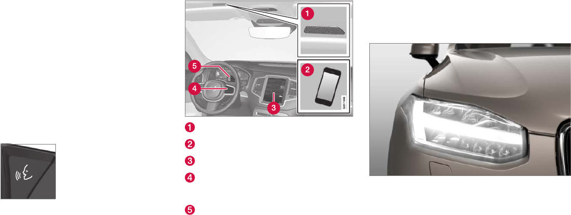
INFOTAINMENT
}}
393
Phone
A Bluetooth-enabled cell phone can be paired
and connected to the vehicle's integrated hands-
free system.
The infotainment system offers hands-free func-
tionality for remote-controlling a number of a cell
phone's features. The phone's integrated controls
can also be used, even when it is connected to
the vehicle.
When the phone has been paired and connected
to the infotainment system, it can be used to
make or receive calls, send or receive text mes-
sages, to stream music, etc., or as an Internet
connection.
The phone is controlled from
the center display but the App
menu (accessed using the
right-side steering wheel key-
pad) and voice commands can
also be used to control certain
functions.
Overview
Microphone
Cell phone
Center display
Keypad for controlling phone functions
shown in the center display and voice com-
mands
Instrument panel
Related information
•Connecting/disconnecting a cell phone
(p. 395)
•Handling phone calls (p. 396)
•Handling text messages (p. 397)
•Pairing a cell phone (p. 393)
•Phone settings (p. 398)
•Text message settings (p. 398)
Pairing a cell phone
A Bluetooth®-enabled cell phone or other device
can be paired and wirelessly connected to the
infotainment system.
When a cell phone or other device is connected,
audio can be streamed to the infotainment sys-
tem. Toggle between the devices by pressing the
TEL and MEDIA buttons to access the respective
sources' functions.
Before a Bluetooth device can be used with
the infotainment system, it has to be paired
("registered").
This procedure only needs to be done once for
each device (a maximum of 20 Bluetooth devices
can be paired to the system). Once a device has
been paired and its Bluetooth function is acti-
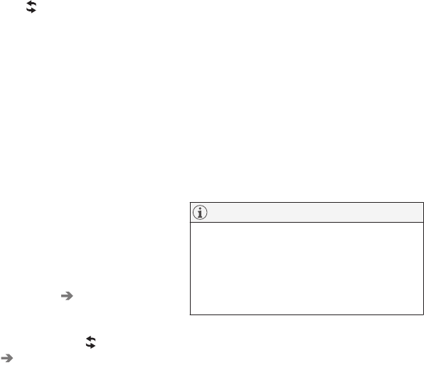
||
INFOTAINMENT
394
vated, it can then be selected for use (wirelessly
connected) to the vehicle's infotainment system.
Two Bluetooth devices can be connected at the
same time. However, if two cell phones are con-
nected, only the most recently connected one
can be used as a phone. The other one can be
used to e.g., to stream audio or video. To change
what the phone will be used for, see the article
"Bluetooth settings."
A paired and connected cell phone can also be
used to connect the vehicle to the Internet. To do
so, its tethering/personal hotspot function must
be activated.
There are two ways of pairing a Bluetooth device
to the infotainment system:
•Searching for the phone (or other device)
from the vehicle
•Searching for the vehicle from the phone (or
other device)
The following instructions assume that a cell
phone is to be paired to the infotainment system
but the procedure is the same for any Bluetooth
device.
Alternative 1: searching for the phone
from the vehicle
1. Make the phone discoverable/visible using
its Bluetooth function. Refer to the phone's
user guide if necessary.
2. Open the Phone view on the center display.
>•If no phones have been paired to the
vehicle, tap Add phone.
•If a list of phones is displayed, tap
Change and tap Add phone in
the pop-up window.
3. Tap the name of the phone to be connected.
4. Check that the code displayed in the vehicle
is the same as the one in the phone. Confirm
in both places.
5. For the phone selected, accept or cancel the
alternatives for the phone book (list of con-
tacts), text messages, etc. Full functionality
may not be available in all cell phones.
6. To connect the vehicle to the Internet via the
phone's Bluetooth function, activate the
phone's function for tethering/personal hot-
spot, etc.
Alternative 2: searching for the vehicle
from the phone
1. Open the center display's Phone view.
•If no phones have been paired to the vehi-
cle, tap Add phone Make vehicle
discoverable.
•If a phone has previously been paired to
the vehicle, tap Change and tap Add
phone Make vehicle discoverable in
the pop-up window.
2. Activate the phone's Bluetooth function.
3. Search in the phone for Bluetooth devices.
> A list of Bluetooth devices will be dis-
played.
4. Select the vehicle's name in the list.
5. Check that the code displayed in the phone
is the same as the one in the vehicle. Con-
firm in both places.
6. For the phone selected, accept or cancel the
alternatives for the phone book (list of con-
tacts), text messages, etc. Full functionality
may not be available in all cell phones.
7. To connect the vehicle to the Internet via the
phone's Bluetooth function, activate the
phone's function for tethering/personal hot-
spot, etc.
NOTE
If your cell phone's operating system is upda-
ted, this may break the connection between
the phone and the vehicle. If this happens,
delete the phone from the list of paired
phones and repeat the pairing procedure
described in this article.
Compatible cell phones
Many of the cell phones available today have
Bluetooth functionality but not all of them are
fully compatible with the vehicle. Go to

INFOTAINMENT
}}
395
www.volvocars.com for a list of compatible
phones or contact your Volvo retailer.
Related information
•Connecting/disconnecting a cell phone
(p. 395)
•Handling phone calls (p. 396)
•Handling text messages (p. 397)
•Phone settings (p. 398)
•Bluetooth settings (p. 412)
Connecting/disconnecting a cell
phone
Once a cell phone or other Bluetooth device has
been paired to the infotainment system, it can be
connected, disconnected or removed from the
list of available devices.
Connecting automatically
1. Before switching on the vehicle's ignition, be
sure that the phone's Bluetooth and personal
hotspot (tethering) functions are activated.
2. Switch on the ignition.
> The phone (or other device) will be con-
nected to the system and can be used
wirelessly.
Connecting manually
1. Be sure that the phone's Bluetooth and per-
sonal hotspot (tethering) functions are acti-
vated.
2. In the center display, open Phone view and
tap Change phone.
> A list of available Bluetooth devices (ones
that have already been paired to the info-
tainment system) will be displayed.
3. Tap the name of the phone or other device
to be connected.
> The phone (or other device) will be con-
nected.
Disconnecting a phone
–Deactivate the phone's Bluetooth function.
If a phone is carried out of range of the vehicle, it
will automatically be disconnected.
If a call in progress when this is done, the call will
be transferred from the vehicle's speakers/micro-
phone to the cell phone.
Changing phones
1. In the center display, open Phone view.
2. Tap Change .
> A list of available Bluetooth devices (ones
that have already been paired to the info-
tainment system) will be displayed.
3. Tap the name of the phone (or other device)
to be connected.
Removing a phone (or other device)
from the list
1. In the center display, open Phone view.
2. Tap Settings Communication
Bluetooth.
> A list of available Bluetooth devices (ones
that have already been paired to the info-
tainment system) will be displayed.
3. Tap the name of the phone to be deleted
from the list.
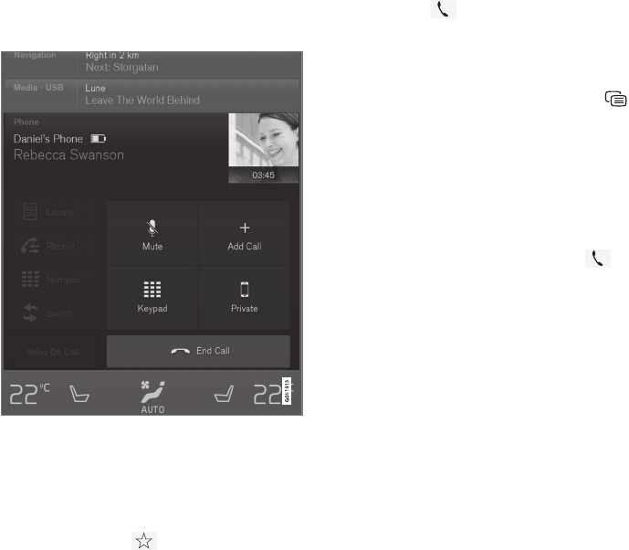
||
INFOTAINMENT
396
4. Tap Remove device and confirm.
> The phone or other device is no longer
paired to the vehicle. Before this device
can be used again, the pairing procedure
will have to be repeated.
Related information
•Pairing a cell phone (p. 393)
Handling phone calls
Calls can be made to one or more parties.
Making calls
1. In the center display, open Phone view.
2. Initiate a call from: recently made calls, the
phone book (list of contacts) or enter a num-
ber. Search for or scroll to a contact in the
phone book. Tap in the phone book to
add a contact to your list of Favorites.
3. Tap Call or .
4. Tap End call to end a phone call.
Calls can also be made from the list of recent
calls using the App menu, which can be opened
using the right-side steering wheel keypad's
symbol.
Making multiple calls
While a call is in progress:
1. Tap Add call.
2. Select from the list of recent calls or from
the phone book.
3. Tap a line in the list of recent calls or to
call a contact in the phone book.
4. Tap Swap call to toggle between calls.
5. Tap End call to end a phone call.
Group (conference) calls
While multiple calls are in progress:
1. Tap Join calls to merge ongoing calls.
2. Tap End call to end a phone call.
Incoming calls
Information about incoming calls is displayed in
the instrument panel and the center display. Han-
dle the calls using the right-side steering wheel
keypad or the center display.
1. Tap Answer/Reject.
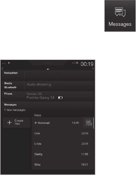
INFOTAINMENT
}}
397
2. Tap End call to end a phone call.
Incoming calls while another call is in
progress
1. Tap Answer/Reject.
2. Tap End call to end a phone call.
Privacy
While a call is in progress:
–Tap Privacy.
> The vehicle's integrated microphone will
be turned off.
•Switch to mobile phone: the hands-free
function will be disconnected and the call will
continue in the cell phone.
•Driver focused: the microphone in the ceil-
ing liner on the passenger's side will be
muted and the call will continue using vehi-
cle's the hands-free function on the driver's
side.
Related information
•Phone (p. 393)
•Voice control for cell phones (p. 118)
•Using the center display (p. 45)
•Using the center display keyboard (p. 31)
•Phone settings (p. 398)
Handling text messages
Text messages can be received and sent from a
connected cell phone.
Text message functionality has to be activated in
certain cell phones and not all phones offer full
compatibility/functionality. Go to
support.volvocars.com for additional information.
Reading text messages in the center
display
1. From App view, tap Messages to open.
2. Tap the name of the contact who sent the
message.
3. Tap Read out to have the message read
aloud or tap the message to be displayed.
Reading new text messages in the
instrument panel
Text messages are only displayed in the instru-
ment panel if this has been selected. See the
article "Text message settings" for more informa-
tion.
–Press the "down" arrow in the right-side
steering wheel keypad to display the mes-
sage.
To have the message read aloud, select
Read out using the keypad.

||
INFOTAINMENT
* Option/accessory, for more information, see Introduction.
398
Sending text messages
1. From App view, tap Messages to open.
2. •To reply to a message: tap the name of
the contact who sent the message and
then tap Answer.
•To create a new message: tap Create
new +. Select the contact who will
receive the message or enter a phone
number.
3. Write the message.
4. Tap Send.
Message notification
See the article "Text message settings" for a list
of possible settings.
Related information
•Text message settings (p. 398)
Phone settings
The following settings can be made for a paired
and connected cell phone.
Cell phones
–Pull down the center display's Top view and
tap Settings Communication Phone
and choose among the following settings:
•Ringtones: select a ring tone (tones from
the cell phone or the vehicle can be
used). Not all cell phones are fully com-
patible and it may not be possible to use
their ring tones in the vehicle. Go to
www.volvocars.com for additional informa-
tion.
•Sort order for contacts: select sort cri-
teria for the phone book (list of contacts).
To show call notifications in the head-up dis-
play*, see the article "Head-up display."
Related information
•Text message settings (p. 398)
•Bluetooth settings (p. 412)
•Phone (p. 393)
•Handling phone calls (p. 396)
•Head-up display (HUD)* (p. 113)
Text message settings
The following settings can be made for text mes-
sages received through a paired and connected
cell phone.
Text message settings
–Pull down the center display's Top view and
tap Settings Communication Text
Messages and choose among the following
settings:
•Notification in center display: shows
text messages in the center display's sta-
tus bar.
•Notification in driver display: shows
text messages in the instrument panel.
With this alternative active, incoming mes-
sages can be handled from the right-side
steering wheel keypad.
•Text message tone: select an audible
signal for incoming text messages.
Related information
•Connecting/disconnecting a cell phone
(p. 395)
•Pairing a cell phone (p. 393)
•Handling text messages (p. 397)
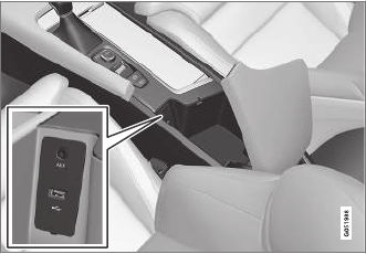
INFOTAINMENT
}}
* Option/accessory, for more information, see Introduction. 399
Connecting a Bluetooth® device
Bluetooth®-enabled devices can be paired and
connected to the infotainment system to stream
media and in some cases connect to the Inter-
net.
Many cell phones and other devices currently on
the market offer wireless Bluetooth® technology.
Consult your Volvo retailer or go to
support.volvocars.com for any questions regar-
ding a device's compatibility with the vehicle's
infotainment system.
The procedure for pairing and connecting a
Bluetooth®-enabled device is the same as for a
cell phone. See the articles "Pairing a cell phone"
and "Connecting/disconnecting a cell phone" for
details.
Related information
•Pairing a cell phone (p. 393)
•Connecting/disconnecting a cell phone
(p. 395)
Connecting a device via the
AUX/USB socket
External audio sources such as an iPod® or mp3
player can be connected to the infotainment sys-
tem via the AUX and USB sockets in the tunnel
console.
AUX/USB sockets in the tunnel console
Media player
The media player can play audio from a CD*,
from external media devices connected to the
USB/AUX sockets or it can stream audio from
an external device connected to the infotainment
system through a Bluetooth connection.
Video can also be viewed from devices con-
nected to the USB socket.
If the vehicle is connected to the Internet, it may
also be possible to listen to web radio, audio
books and to use various music services through
apps.
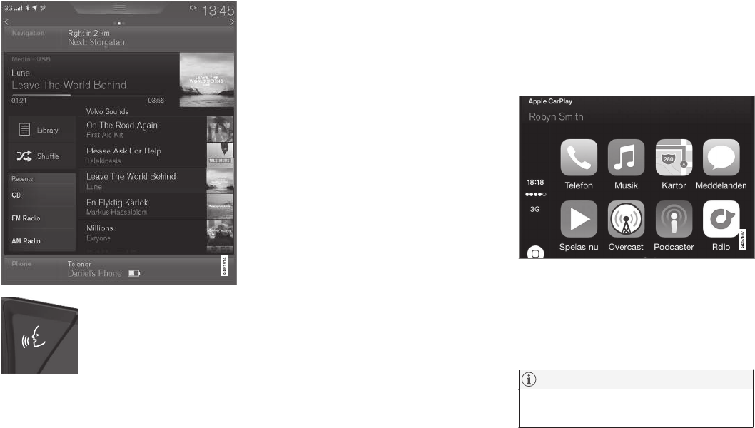
||
INFOTAINMENT
* Option/accessory, for more information, see Introduction.
400
The media player is controlled
from the center display but cer-
tain functions can also be con-
trolled from the right-side
steering wheel keypad or by
using voice commands.
Related information
•Playing media (p. 403)
•Voice control for radio and media (p. 118)
•Radio (p. 383)
•Apps (applications) (p. 411)
•CD (media) player* (p. 403)
•Playing media through the AUX/USB sock-
ets (p. 406)
Apple CarPlay
Apple CarPlay helps make it possible to listen to
music, make phone calls, get directions to a
destination, send/receive text messages and use
Siri while focusing on driving. Apple CarPlay
functions with certain Apple devices.
If the vehicle is not already equipped with
Apple CarPlay, it can be retro-fitted. Contact a
Volvo retailer.
Information about the apps supported and com-
patible cell phones is available from Apple at:
www.apple.com/ios/carplay/.
NOTE
Please be aware that Volvo has no control
over the content of the Apple CarPlay app.

INFOTAINMENT
}}
* Option/accessory, for more information, see Introduction. 401
If a cell phone or a media player is connected via
Bluetooth, it will not be accessible while
Apple CarPlay is active because Bluetooth will be
disabled. To connect the vehicle to the Internet,
use Wi-Fi or the vehicle's integrated modem.
If navigation guidance is being provided by
Apple CarPlay, this will only be shown on the
center display (not on the head-up display* or the
instrument panel).
The Apple CarPlay apps can be controlled from
the center display or voice-controlled using Siri
(the same as for a cell phone). Certain functions
can also be controlled from the right-side steer-
ing wheel keypad. Press and hold the button
to activate Siri.
By using Apple CarPlay you acknowledge
the following: Apple CarPlay is a service
provided by Apple Inc. under its terms and
conditions. Volvo Cars is thus not
responsible for Apple CarPlay or its
features/applications. When using Apple
CarPlay, certain information from your car
(including its position) is transferred to your
iPhone. In relation to Volvo Cars, you are
fully responsible for your and any others
person’s use of Apple CarPlay.
Starting Apple CarPlay
Voice control using Siri must be activated in the
currently connected cell phone before using
Apple CarPlay.
From an iPhone that is connected for the
first time
1. Connect the phone to the USB socket in the
tunnel console.
2. Read the information in the pop-window that
appears and tap OK.
3. Tap Apple CarPlay in the center display's
App view.
4. Read the conditions and tap Accept to con-
nect.
> The Apple CarPlay sub-view will open and
compatible apps will be displayed.
5. Tap the desired app.
> The app will start.
From a previously connected iPhone
1. Connect the phone to the USB socket in the
tunnel console.
>If the automatic start setting has been
chosen, the Apple CarPlay sub-view will
open and compatible apps will be dis-
played.
2. If the automatic start setting has not been
chosen, open the Apple CarPlay app from
the center display's App view.
> The Apple CarPlay sub-view will open and
compatible apps will be displayed.
3. Tap the desired app.
> The app will start.
Apple CarPlay will run in the background if
another app is started in the same sub-view. To
return to Apple CarPlay, tap the Apple CarPlay
icon in App view.
Toggling between Apple CarPlay and
iPod
Apple CarPlay to iPod
1. Tap Settings in the center display's Top
view.
2. Tap Communication Apple CarPlay.
3. Deselect the Apple device's box that will no
longer start Apple CarPlay when it is con-
nected.
4. Disconnect and reconnect the Apple device
to the USB socket.
5. Open the iPod app from App view.
iPod to Apple CarPlay
1. Tap Apple CarPlay in the center display's
App view.
2. Read the conditions in the pop-up window
that appears and tap OK.
3. Disconnect and reconnect the Apple device
to the USB socket.
> The Apple CarPlay sub-view will open.
Related information
•Media player (p. 399)
•Playing media (p. 403)

INFOTAINMENT
402
•Connecting a device via the AUX/USB
socket (p. 399)
•Apple CarPlay settings (p. 402)
Apple CarPlay settings
This article explains settings for a cell phone
connected through Apple CarPlay.
Automatic start
1. Tap Settings in the center display's Top
view.
2. Tap Communication Apple CarPlay and
select the following settings:
•Select the Apple CarPlay box for auto-
matic start when the device's USB cable
is connected.
•Deselect the Apple CarPlay box to disa-
ble automatic start when the device's
USB cable is connected.
A maximum of 20 Apple devices can be stored in
the list. When the list is full, the first (oldest)
device stored will be deleted.
To erase the entire list, a factory reset has to be
performed. See the article "Resetting the set-
tings view."
System volume levels
1. Tap Settings in the center display's Top
view.
2. Tap Sound System Volumes and select
the following settings:
•Voice Control
•Navigation
•Ringtone
Related information
•Apple CarPlay (p. 400)
•Resetting the settings view (p. 111)
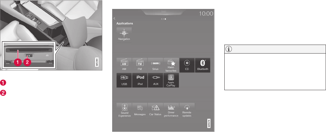
INFOTAINMENT
}}
* Option/accessory, for more information, see Introduction. 403
CD (media) player*
The CD (media) player can play commercially
purchased discs as well as ones that you have
burned yourself. See the article "Media player
technical data" for information about compatible
file formats.
Location of the CD player in the tunnel console
Disc slot
Eject button
Related information
•Media player technical data (p. 408)
Playing media
The media player can controlled from the right-
side steering wheel keypad, the center display or
by using voice commands.
The radio is also controlled from the media
player. See the articles relating to the radio.
Starting a media source
Generic illustration
CD
1. Insert a CD.
2. Open the CD app in the center display's App
view.
3. Select a track.
> Playback will begin.
USB flash drive
1. Insert the flash drive in the USB socket.
2. Open the USB app in the center display's
App view.
3. Select a track.
> Playback will begin.
Mp3 player and iPod®
NOTE
Use the iPod app ( not the USB app) to start
playback.
When an iPod is the media source, the info-
tainment system will use a menu structure
similar to the iPod's own menu structure.
1. Connect the device.
2. Start playback in the connected device.
3. Open the iPod, USB, AUX) app in the cen-
ter display's App view.
> Playback will begin.
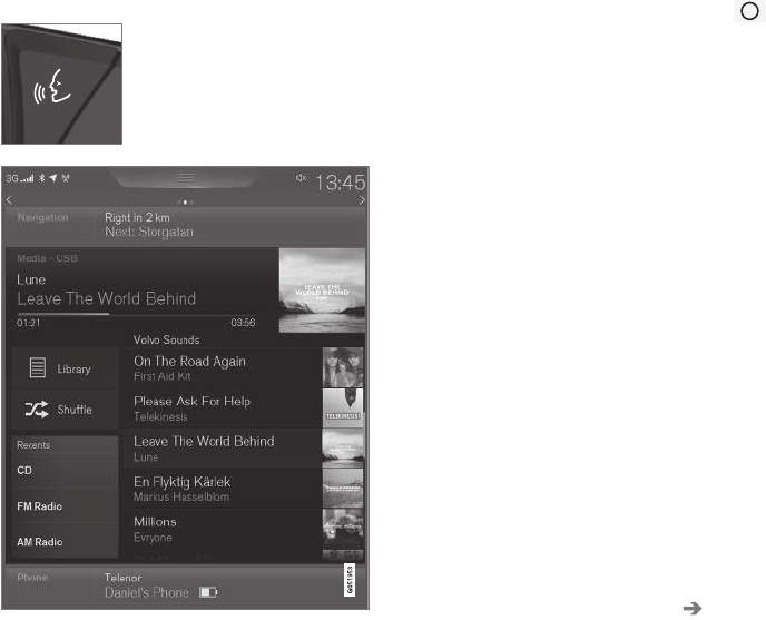
||
INFOTAINMENT
404
Bluetooth-connected device
1. Connect the device.
2. Activate Bluetooth in the device.
3. Start playback from the connected device.
4. Open the Bluetooth app in the center dis-
play's App view.
> Playback will begin.
Internet media
1. Connect the vehicle to the Internet.
2. Open the app in the center display's App
view.
> Playback will begin.
Video
1. Connect the device.
2. Open the USB app in the center display's
App view.
3. Tap the title of the video content to be
played.
> Playback will begin.
Apple CarPlay
Apple CarPlay is described in a separate article.
Controlling and changing media
The media player can be con-
trolled using voice commands,
the right-side steering wheel
keypad or the center display.
Volume: use the buttons on the keypad or turn
the control under the center display to raise or
lower the volume.
Play/pause: tap the track's image, press the
symbol on the keypad or press the button under
the center display.
Change tracks: tap the desired track on the cen-
ter display, press the < > buttons under the cen-
ter display or use the keypad.
Fast forward/reverse, move within a track: press
the time axis on the center display and drag from
side to side, press and hold the < > buttons
under the center display or use the keypad.
Change media source: Tap a media source under
Recents, tap the desired app in the center dis-
play's App view or use the keypad.
Library: tap to play a track from the library.
Shuffle: tap to play tracks in random order.
Similar: tap to use Gracenote to search for simi-
lar music on the USB device and create a playlist
based on the results. The playlist can contain up
to 50 tracks.
Change device: tap to toggle between USB
devices if more than one is connected.
Video settings
The following can be adjusted with the video
player in full screen or by opening the center dis-
play's Top view and tapping Settings Video:
Primary Audio Default Language, Subtitle
and Primary Subtitle Default Language.
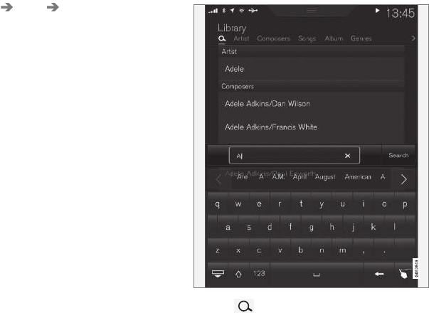
INFOTAINMENT
* Option/accessory, for more information, see Introduction. 405
Play DivX®
This DivX device must be registered in order to
play purchased DivX Video-on-Demand (VOD)
movies.
1. Open the center display's Top view and tap
Settings Video DivX® VOD to get a
registration code.
2. Go to vod.divx.com for additional information
and to complete the registration process.
Related information
•CD (media) player* (p. 403)
•Media player (p. 399)
•Voice control for radio and media (p. 118)
•Apps (applications) (p. 411)
•Connecting a Bluetooth® device (p. 399)
•Connecting a device via the AUX/USB
socket (p. 399)
•Gracenote (p. 407)
•Connecting to the Internet (p. 410)
•Media searches (p. 405)
•Video (p. 408)
•Apple CarPlay (p. 400)
Media searches
Searches can be made for information such as
artists, composers, song titles, albums, video,
audio books, playlists and podcasts (digital
media on the Internet).
1. Tap .
> The center display's Search view opens
and the keyboard will be displayed.
2. Enter a search word/phrase.
3. Tap Search.
> The infotainment system will search
through all connected devices and any
results will be displayed by category.
Related information
•Media player (p. 399)
•Playing media (p. 403)
•Using the center display keyboard (p. 31)
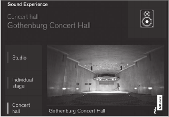
INFOTAINMENT
* Option/accessory, for more information, see Introduction.
406
Playing media through the
AUX/USB sockets
An external media device, such as an iPod or an
mp-3 player can be connected to the infotain-
ment system.
A device with rechargeable batteries can be
recharged when it is connected to the USB
socket (if the ignition is on or the engine is run-
ning).
To simplify the use of a USB flash drive, it is
advisable to only store files with compatible file
formats on it. It will take considerably longer for
the system to index the files on the drive if it con-
tains anything other than compatible files.
In addition to audio, the vehicle's media player
also supports video playback when the external
device is connected to the USB socket.
Certain mp-3 players have proprietary file formats
that are not supported by the infotainment sys-
tem.
Related information
•Connecting a device via the AUX/USB
socket (p. 399)
Streaming media through a
Bluetooth connection
The media player is equipped with Bluetooth®
for streaming audio files from external
Bluetooth®-enabled devices.
Related information
•Connecting a Bluetooth® device (p. 399)
•Playing media (p. 403)
•Voice control for radio and media (p. 118)
•Media player (p. 399)
•Ignition modes (p. 360)
•Media player technical data (p. 408)
Media sound settings
Sound settings for the media player can be per-
sonalized.
Concert hall sound setting
1. Tap Settings in the center display's Top
view.
2. Tap Sound and select among the following:
•Sound Experience*: this feature offers sev-
eral ways of adapting media sound settings
to replicate e.g., a concert hall or a recording
studio. These settings override any of the
ones below that may have been adjusted.
•Tone: personal settings for bass, treble,
equalizer, etc.
•Balance: adjust the front/rear and left/right
sound settings in the passenger compart-
ment.

INFOTAINMENT
407
System volumes for media
Open the center display's Top view and tap
Settings Sound System Volumes:
•AUX: an external device (e.g., an mp3 player,
an iPod, etc.) connected to the AUX socket
may have a different volume level than the
one set for the infotainment system (e.g., for
the radio). This setting enables you to adjust
the AUX socket's volume. Please note that if
this volume is set too high, sound quality may
be affected.
•Speed and Volume Compensation: the
infotainment system will compensate for dis-
rupting noises in the passenger compart-
ment by increasing media volume in relation
to the vehicle's speed. This can be set to one
of several different levels.
Related information
•Playing media (p. 403)
•Sound settings (p. 382)
Gracenote
Gracenote identifies artists, albums, tracks and
any associated images that can be displayed
during playback.
Gracenote MusicID® is a standard for music rec-
ognition.
Activating/deactivating Gracenote
When activated, Gracenote data will replace origi-
nal data.
1. Tap Settings in the center display's Top
view.
2. Tap Media Gracenote®.
3. Activate/deactivate Gracenote by tapping the
Gracenote® box.
4. Select among the following Gracenote alter-
natives:
•Gracenote® Online Look Up: Gracenote
will search through its online database for
information about the currently playing
media.
•Gracenote® Multiple Results: select how
Gracenote data is to be displayed if there are
several search results.
1: the file's original data will be used.
2: Gracenote data will be used.
3: Gracenote or original data can be
selected.
•None: no results will be shown.
Related information
•Infotainment system license information
(p. 416)
•Playing media (p. 403)

INFOTAINMENT
408
Video
The media player can play video from USB-con-
nected devices.
No video will be available when the vehicle is
moving. Video will resume playing when the vehi-
cle is stationary.
See the article "Media player technical data" for a
list of video formats supported by the media
player.
Related information
•Playing media (p. 403)
•Media player (p. 399)
•Media player technical data (p. 408)
Media player technical data
The following tables list compatible file formats
and other technical specifications for the media
player.
Audio files
For-
mat
File extension Codec
MP3 .mp3 MPEG1 Layer III,
MPEG2 Layer III,
MP3 Pro (mp3
compatible),
MP3 HD (mp3
compatible)
AAC .m4a, .m4b, .aac AAC LC (MPEG-4
part III Audio),
HE-AAC (aacPlus
v1/v2)
WMA .wma WMA8/9,
WMA9/10 Pro
WAV .wav LPCM
FLAC .flac FLAC
Video files
Format File extension
MP4 .mp4, .m4v
MPEG-PS .mpg, .mp2, .mpeg, .m1v
Format File extension
AVI .avi
AVI (DivX) .avi, .divx
ASF .asf, .wmv
MKV .mkv
Subtitles
Format File extension
SubViewer .sub
SubRip .srt
SSA .ssa
INFOTAINMENT
}}
* Option/accessory, for more information, see Introduction. 409
DivX®
DivX Certified devices have been tested for high
quality DivX (.divx, .avi) video playback. When you
see the DivX logo, you have the freedom to play
your favorite DivX movies.
Profile DivX Home Theater
Video codec DivX, MPEG-4
Resolution 720x576
Audio speed
(bit rate)
4.8Mbps
Frame per sec-
ond
30 fps
File extension .divx, .avi
Max. file size 4 GB
Audio codec MP3, AC3
Subtitles XSUB
Special func-
tions
Multiple subtitles, multiple
audio, resume play
Reference Meets all requirements of
the DivX® Home Theater
profile. Visit divx.com for
more information and soft-
ware tools to convert your
files into DivX® Home
Theater. video.
Storing information on a USB device
In order for the system to read data stored on a
USB device, the following specifications must be
met. Any folder structures will not be shown in
the center display during playback.
Max. number
Files 15,000
Folders 1,000
Folder levels 8
Playlists 100
Tracks in a playlist 1,000
Subfolders No limit
Related information
•CD (media) player* (p. 403)
Internet connected vehicle
Connecting to the Internet makes it possible to
e.g., use certain navigation services, listen to
web radio, stream music using apps, contact a
retailer and download software.
The vehicle can connect to the Internet using
Bluetooth, Wi-Fi, a cell phone connected by a
cable to the USB socket or via the integrated
modem.
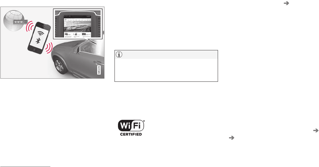
||
INFOTAINMENT
410
When connected, it is possible to share (tether) a
Wi-Fi-hotspot to allow other devices to use the
connection5.
Connection status is shown in the center dis-
play's status bar.
Related information
•Connecting to the Internet (p. 410)
•Apps (applications) (p. 411)
•Booking service and repairs (p. 499)
•System updates (p. 498)
•Volvo ID (p. 26)
•Symbols in the center display status bar
(p. 43)
•Tethering (Wi-Fi sharing) (p. 414)
Connecting to the Internet
Connect the vehicle to the Internet using
Bluetooth, Wi-Fi, by connecting a phone through
a cable to the USB socket or via the vehicle's
integrated modem.
The cell phone and the network service provider
must support Internet sharing (tethering) and the
subscription must included data transfer.
See the terms and confidentiality information at
support.volvocars.com before connecting to the
Internet.
NOTE
When using Apple CarPlay, an Internet con-
nection can only be established by using
Wi-Fi or the vehicle's integrated modem.
Connect using Bluetooth
See the article "Pairing a cell phone."
Connect using Wi-Fi
1. Activate tethering/personal hotspot in the
cell phone.
2. Tap Settings in the center display's Top
view.
3. Tap Communication Wi-Fi.
4. Tap Wi-Fi to activate/deactivate.
5. Tap the name of the network to be used.
6. Enter the network password.
7. If a different connection was used previously,
confirm the connection change.
> The vehicle will connect to the network.
Please be aware that certain cell phones disable
tethering when the connection to the vehicle has
been broken, e.g., when the phone has been
removed from the vehicle. In such cases, the
phone's tethering function will have to be reacti-
vated the next time the phone is used to connect
to the Internet.
When a phone is connected to the vehicle, it is
saved for future use. When a max. number of 50
have been saved, the first one connected will be
deleted. To show the list of saved networks or to
manually delete a network, tap Settings Wi-Fi
Saved networks.
See the article "Wi-Fi technology and security"
for network connection requirements.
5This does not apply to Wi-Fi connections.
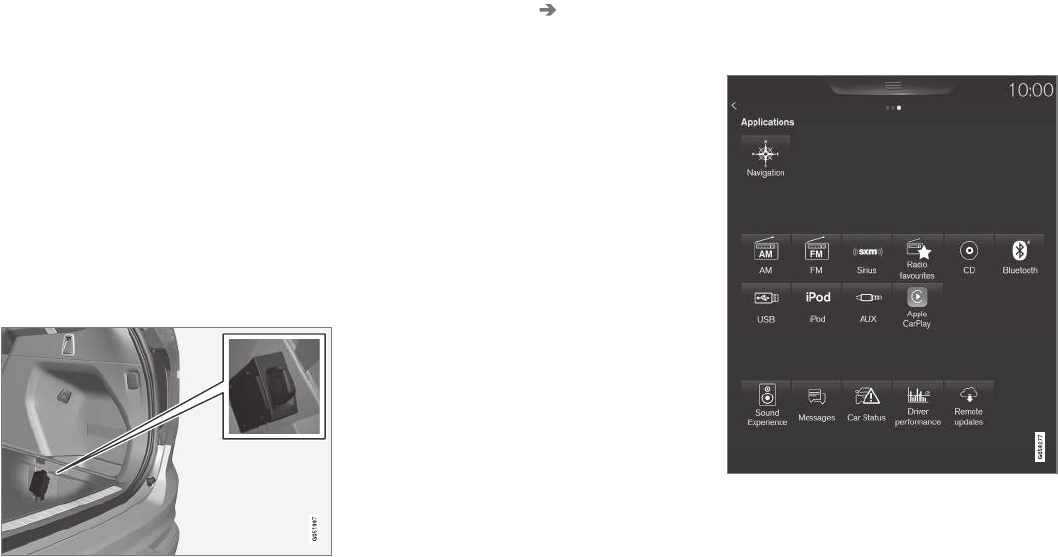
INFOTAINMENT
}}
411
Connect using a cable connected to the
USB socket
1. Connect the phone via a cable to the USB
socket in the tunnel console storage com-
partment.
2. Activate USB tethering in the cell phone.
3. If a different connection was used previously,
confirm the connection change.
> The vehicle will connect to the network.
Connect using the vehicle's integrated
modem
When the vehicle is connected using the modem,
Volvo On Call services will use the connection.
1. Insert a personal SIM card in the holder.
2. Tap Settings in the center display's Top
view.
3. Tap Communication Vehicle Modem
Internet.
4. Tap Vehicle modem Internet to activate/
deactivate.
5. If a different connection was used previously,
confirm the connection change.
6. Enter the SIM card's PIN code.
> The vehicle will connect to the network.
Related information
•Pairing a cell phone (p. 393)
•Connecting/disconnecting a cell phone
(p. 395)
•Connecting a device via the AUX/USB
socket (p. 399)
•Wi-Fi technology and security (p. 415)
•Apple CarPlay (p. 400)
Apps (applications)
Apps (applications) are programs used to con-
trol some of the vehicle's features and functions.
The center display's App view (generic illustration)
Several basic apps are always available and oth-
ers can be downloaded. Downloadable apps
include navigation services, web radio, streaming
music services, retailer contact and software
downloads.

||
INFOTAINMENT
412
Some apps are only available if the vehicle is
connected to the Internet.
–In the center display's App view, tap an app
to start it.
Related information
•Internet connected vehicle (p. 409)
•Downloading, updating and uninstalling apps
(p. 413)
•Changing settings in different types of apps
(p. 44)
Bluetooth settings
The following settings apply to a Bluetooth-con-
nected cell phone.
Bluetooth
1. Tap Settings in the center display's Top
view.
2. Tap Communication Bluetooth and
select among the following settings:
•Previously paired devices: lists the
devices that are paired and connected to
the vehicle.
•Internet connection: select to connect
to the Internet using the device's
Bluetooth connection.
•Add device: begin the procedure to pair
a new device.
•Remove device: remove a paired device.
•Allowed services for this device: select
the services that the device will be used
for.
Bluetooth compliance
United States
FCC CAUTION
Changes or modifications not expressly approved
by the party responsible for compliance could
void the user's authority to operate the equip-
ment. This transmitter must not be co-located or
operated in conjunction with any other antenna
or transmitter.
Canada
This device complies with Industry Canada
licence-exempt RSS standard(s). Operation is
subject to the following two conditions:
(1) this device may not cause interference, and
(2) this device must accept any interference,
including interference that may cause undesired
operation of the device.
Related information
•Internet connected vehicle (p. 409)
•Pairing a cell phone (p. 393)
•Phone (p. 393)
•Media player (p. 399)
•Connecting/disconnecting a cell phone
(p. 395)
INFOTAINMENT
413
Downloading, updating and
uninstalling apps
Apps can be added (downloaded), kept up-to-
date or deleted.
NOTE
Downloading data may affect other services
that transfer data such as web radio, stream-
ing music, etc. If this occurs, a download in
progress can be cancelled or the other serv-
ice can be temporarily turned off.
Apps are managed via the
Remote update service in
the center display's App view.
To download, update or delete
apps, the vehicle must be con-
nected to the Internet.
Downloading an app
1. Open the Remote update service app.
2. Select Explore to open a list of apps that
are available but which are not installed in
the vehicle. Tap anywhere in a line for an app
to expand the list for additional information.
3. Select Install to start downloading the app. It
will remain in the list and a new download
can be initiated if necessary.
> Download status will be indicated while it
is in progress.
A message will be displayed if a download
cannot be started immediately. The app
will remain in the list and a new download
can be initiated if necessary.
Cancelling (aborting) a download
–Tap Abort to cancel a download that is cur-
rently underway.
Only a download can be cancelled. If the installa-
tion phase has begun, it cannot be interrupted.
Updating apps
If an app is being used while an update is in pro-
gress, it will be restarted to complete the update.
Update (install) all
1. Open the Remote update service app.
2. Select Install all.
> The update will begin.
Updating certain apps
1. Open the Remote update service app.
2. Select Application updates to open a list
of available updates.
3. Find the desired app and select Install.
> The update will begin.
Uninstalling an app
An app being used must be closed before it can
be uninstalled.
1. Open the Remote update service app.
2. Select Application updates to open a list
of apps that have been installed.
3. Find the desired app and select Uninstall to
begin uninstalling the app.
> When the app has been uninstalled, it will
be removed from the list.
Related information
•Internet connected vehicle (p. 409)
•Media player (p. 399)
•System updates (p. 498)

INFOTAINMENT
414
Internet connection troubleshooting
The following are factors that may affect the
vehicle's Internet connection.
The amount of data being transmitted depends
on the services or apps that are currently in use.
For example, streaming audio requires a great
deal of data to be transmitted, which requires a
good connection and a strong signal.
Cell phone to the vehicle
Connection speed may vary depending on the
location of the cell phone in the vehicle. Move the
phone closer to the center display to increase
signal strength. Be sure that there are no
obstructing/screening objects between the
phone and the screen.
Cell phone to the network operator
The speed of the mobile network may vary
depending on coverage/reception in the vehicle's
location. Reception is generally poorer in tunnels,
in mountainous areas, in deep valleys or indoors.
Connection speed may also depend on the type
of subscription that you have with the service
provider.
Contact your service provider in the event of data
transmission problems.
Related information
•Internet connected vehicle (p. 409)
•Connecting to the Internet (p. 410)
Tethering (Wi-Fi sharing)
When the vehicle is connected to the Internet,
this connection can be shared (tethered) with
other devices6.
The network service provider (the SIM card) must
support tethering.
1. Open the center display's Top view.
2. Tap Settings Communication
Vehicle Wi-Fi Hotspot.
3. Tap Network name and assign a name to
the hotspot.
4. Tap Password and create a password to be
used by devices trying to connect (tether) to
the hotspot.
5. Tap Frequency band and select a fre-
quency that the hotspot will use to transmit
data. This may not be possible in all markets.
6. Activate/deactivate by tapping the Vehicle
Wi-Fi Hotspot box.
7. If another connection has been used previ-
ously, confirm the change of connections.
> It is now possible for external devices to
connect to the vehicle's Wi-Fi hotspot.
Connection status will be indicated in a symbol in
the center display's status bar.
Tap Connected devices to see a list of con-
nected devices.
Related information
•Internet connected vehicle (p. 409)
•Wi-Fi technology and security (p. 415)
•Symbols in the center display status bar
(p. 43)
•Internet connection troubleshooting (p. 414)
6Does not apply for a Wi-Fi connection.

INFOTAINMENT
}}
415
Deleting Wi-Fi networks
Networks that are not used can be deleted.
1. Tap Settings in the center display's Top
view.
2. Tap Wi-Fi Saved networks.
3. Tap Forget to remove the network.
4. Confirm the selection.
> The vehicle will no longer connect to the
deleted network.
Deleting all networks
All networks can be deleted at the same time by
returning (resetting) to factory settings.
If this is done, all user data and settings will be
reset to their default settings.
Related information
•Internet connected vehicle (p. 409)
•Connecting to the Internet (p. 410)
Wi-Fi technology and security
The following are types of networks can be con-
nect to.
It is possible to connect to the following types of
networks:
•Frequency: 2.4 or 5 GHz7.
•Standards: 802.11 a/b/g/n.
•Security type: WPA2-AES-CCMP.
The vehicle's Wi-Fi system is designed to man-
age Wi-Fi devices in the vehicle.
If several devices are using a frequency at the
same time, this may result in poorer performance.
Related information
•Internet connected vehicle (p. 409)
•Connecting to the Internet (p. 410)
•Tethering (Wi-Fi sharing) (p. 414)
•Internet connection troubleshooting (p. 414)
Vehicle modem settings
The vehicle is equipped with a modem that can
be used to connect the vehicle to the Internet. It
is also possible to share (tether) this connection
via Wi-Fi.
1. Tap Settings in the center display's Top
view.
2. Tap Communication Vehicle Modem
Internet and choose among the following
settings:
•Vehicle modem Internet: select to use the
vehicle's modem to connect to the Internet.
•Data usage: %s: Tap Reset to restart
(reset) the counter for the amount of data
sent/received.
•Network
Select
carrier: select a service provider automati-
cally or manually.
Data
roaming: select to allow the vehicle to con-
nect to another network if the standard net-
work is not available (e.g., if you are driving in
another country). This could entail additional
charges, consult your service provider.
•SIM card PIN
7Selecting a frequency is not possible in all markets.

||
INFOTAINMENT
416
Change PIN: enter max. 4 digits.
Disable
PIN: Allow access to the SIM card without
requiring a PIN code.
•Send request code: this is used to down-
load the balance remaining on a SIM card.
This is specific to your service provider.
Related information
•Internet connected vehicle (p. 409)
•Connecting to the Internet (p. 410)
Infotainment system license
information
The following license information pertains to Vol-
vo's agreements with certain manufacturers/
developers.
Bowers & Wilkins
Bowers & Wilkins and B&W are trademarks of
the B&W Group Ltd. Nautilus is a trademark of
B&W Group Ltd. Kevlar is a registered trademark
of DuPont.
Dirac Live
Dirac Live technology has been used in the
development and tuning of the sound in order to
ensure a world-class sound experience. Dirac
Live and the D-symbol are registered trademarks
of Dirac Research AB.
DivX®
DivX®, DivX Certified® and asociated logos are
trademarks of DivZ, LLC and are used under
license. och associerade logotyper är varumärken
som tillhör Rovi Corporation eller dess dotterbo-
lag och används på licens.
Patent number
Covered by one or more of the following U.S. pat-
ents: 7,295,673; 7,460,668; 7,515,710;
8,656,183; 8,731,369; RE45,052."

INFOTAINMENT
}}
417
Gracenote®
Gracenote, Gracenote logo and logotype,
"Powered by Gracenote" and Gracenote MusicID
are either registered trademarks or trademarks of
Gracenote, Inc in the United States and/or other
countries.
Gracenote® End User License Agreement
This application or device contains software from
Gracenote, Inc. of Emeryville, California (“Grace-
note”). The software from Gracenote (the “Grace-
note Software”) enables this application to per-
form disc and/or file identification and obtain
music-related information, including name, artist,
track, and title information (“Gracenote Data”)
from online servers or embedded databases (col-
lectively, “Gracenote Servers”) and to perform
other functions. You may use Gracenote Data
only by means of the intended End-User func-
tions of this application or device.
You agree that you will use Gracenote Data, the
Gracenote Software, and Gracenote Servers for
your own personal non-commercial use only. You
agree not to assign, copy, transfer or transmit the
Gracenote Software or any Gracenote Data to
any third party. YOU AGREE NOT TO USE OR
EXPLOIT GRACENOTE DATA, THE GRACE-
NOTE SOFTWARE, OR GRACENOTE SERVERS,
EXCEPT AS EXPRESSLY PERMITTED HEREIN.
You agree that your non-exclusive license to use
the Gracenote Data, the Gracenote Software, and
Gracenote Servers will terminate if you violate
these restrictions. If your license terminates, you
agree to cease any and all use of the Gracenote
Data, the Gracenote Software, and Gracenote
Servers. Gracenote reserves all rights in Grace-
note Data, the Gracenote Software, and the
Gracenote Servers, including all ownership rights.
Under no circumstances will Gracenote become
liable for any payment to you for any information
that you provide. You agree that Gracenote, Inc.
may enforce its rights under this Agreement
against you directly in its own name.
The Gracenote service uses a unique identifier to
track queries for statistical purposes. The pur-
pose of a randomly assigned numeric identifier is
to allow the Gracenote service to count queries
without knowing anything about who you are. For
more information, see the web page for the
Gracenote Privacy Policy for the Gracenote serv-
ice.
The Gracenote Software and each item of Grace-
note Data are licensed to you “AS IS.” Gracenote
makes no representations or warranties, express
or implied, regarding the accuracy of any Grace-
note Data from in the Gracenote Servers. Grace-
note reserves the right to delete data from the
Gracenote Servers or to change data categories
for any cause that Gracenote deems sufficient.
No warranty is made that the Gracenote Software
or Gracenote Servers are error-free or that func-
tioning of Gracenote Software or Gracenote
Servers will be uninterrupted. Gracenote is not
obligated to provide you with new enhanced or
additional data types or categories that Grace-
note may provide in the future and is free to dis-
continue its services at any time.
GRACENOTE DISCLAIMS ALL WARRANTIES
EXPRESS OR IMPLIED, INCLUDING, BUT NOT
LIMITED TO, IMPLIED WARRANTIES OF MER-
CHANTABILITY, FITNESS FOR A PARTICULAR
PURPOSE, TITLE, AND NON-INFRINGEMENT.
GRACENOTE DOES NOT WARRANT THE
RESULTS THAT WILL BE OBTAINED BY YOUR
USE OF THE GRACENOTE SOFTWARE OR
ANY GRACENOTE SERVER. IN NO CASE WILL
GRACENOTE BE LIABLE FOR ANY CONSE-
QUENTIAL OR INCIDENTAL DAMAGES OR
FOR ANY LOST PROFITS OR LOST REVENUES.
© Gracenote, Inc. 2009
Sensus software
This software uses parts of sources from clib2
and Prex Embedded Real-time OS - Source
(Copyright (c) 1982, 1986, 1991, 1993, 1994),
and Quercus Robusta (Copyright (c) 1990,
||
INFOTAINMENT
418
1993), The Regents of the University of
California. All or some portions are derived from
material licensed to the University of California by
American Telephone and Telegraph Co. or Unix
System Laboratories, Inc. and are reproduced
herein with the permission of UNIX System
Laboratories, Inc. Redistribution and use in
source and binary forms, with or without
modification, are permitted provided that the
following conditions are met: Redistributions of
source code must retain the above copyright
notice, this list of conditions and the following
disclaimer. Redistributions in binary form must
reproduce the above copyright notice, this list of
conditions and the following disclaimer in the
documentation and/or other materials provided
with the distribution. Neither the name of the
<ORGANIZATION> nor the names of its
contributors may be used to endorse or promote
products derived from this software without
specific prior written permission. THIS
SOFTWARE IS PROVIDED BY THE COPYRIGHT
HOLDERS AND CONTRIBUTORS "AS IS" AND
ANY EXPRESS OR IMPLIED WARRANTIES,
INCLUDING, BUT NOT LIMITED TO, THE
IMPLIED WARRANTIES OF MERCHANTABILITY
AND FITNESS FOR A PARTICULAR PURPOSE
ARE DISCLAIMED. IN NO EVENT SHALL THE
COPYRIGHT OWNER OR CONTRIBUTORS BE
LIABLE FOR ANY DIRECT, INDIRECT,
INCIDENTAL, SPECIAL, EXEMPLARY, OR
CONSEQUENTIAL DAMAGES (INCLUDING,
BUT NOT LIMITED TO, PROCUREMENT OF
SUBSTITUTE GOODS OR SERVICES; LOSS OF
USE, DATA, OR PROFITS; OR BUSINESS
INTERRUPTION) HOWEVER CAUSED AND ON
ANY THEORY OF LIABILITY, WHETHER IN
CONTRACT, STRICT LIABILITY, OR TORT
(INCLUDING NEGLIGENCE OR OTHERWISE)
ARISING IN ANY WAY OUT OF THE USE OF
THIS SOFTWARE, EVEN IF ADVISED OF THE
POSSIBILITY OF SUCH DAMAGE.
This software is based in part on the work of the
Independent JPEG Group.
This software uses parts of sources from
"libtess". The Original Code is: OpenGL Sample
Implementation, Version 1.2.1, released January
26, 2000, developed by Silicon Graphics, Inc. The
Original Code is Copyright (c) 1991-2000 Silicon
Graphics, Inc. Copyright in any portions created
by third parties is as indicated elsewhere herein.
All Rights Reserved. Copyright (C) [1991-2000]
Silicon Graphics, Inc. All Rights Reserved.
Permission is hereby granted, free of charge, to
any person obtaining a copy of this software and
associated documentation files (the "Software"),
to deal in the Software without restriction,
including without limitation the rights to use,
copy, modify, merge, publish, distribute,
sublicense, and/or sell copies of the Software,
and to permit persons to whom the Software is
furnished to do so, subject to the following
conditions: The above copyright notice including
the dates of first publication and either this
permission notice or a reference to http://
oss.sgi.com/projects/FreeB/ shall be included in
all copies or substantial portions of the Software.
THE SOFTWARE IS PROVIDED "AS IS",
WITHOUT WARRANTY OF ANY KIND,
EXPRESS OR IMPLIED, INCLUDING BUT NOT
LIMITED TO THE WARRANTIES OF
MERCHANTABILITY, FITNESS FOR A
PARTICULAR PURPOSE AND
NONINFRINGEMENT. IN NO EVENT SHALL
SILICON GRAPHICS, INC. BE LIABLE FOR ANY
CLAIM, DAMAGES OR OTHER LIABILITY,
WHETHER IN AN ACTION OF CONTRACT,
TORT OR OTHERWISE, ARISING FROM, OUT
OF OR IN CONNECTION WITH THE SOFTWARE
OR THE USE OR OTHER DEALINGS IN THE
SOFTWARE. Except as contained in this notice,
the name of Silicon Graphics, Inc. shall not be
used in advertising or otherwise to promote the
sale, use or other dealings in this Software
without prior written authorization from Silicon
Graphics, Inc.
This software is based in parts on the work of the
FreeType Team.
This software uses parts of SSLeay Library:
Copyright (C) 1995-1998 Eric Young
(eay@cryptsoft.com). All rights reserved
Linux software
This product contains software licensed under
GNU General Public License (GPL) or GNU
Lesser General Public License (LGPL), etc.
INFOTAINMENT
}}
419
You have the right of acquisition, modification,
and distribution of the source code of the GPL/
LGPL software.
You may download Source Code from the
following website at no charge: http://
www.embedded-carmultimedia.jp/linux/oss/
download/TVM_8351_013
The website provides the Source Code "As Is"
and without warranty of any kind.
By downloading Source Code, you expressly
assume all risk and liability associated with
downloading and using the Source Code and
complying with the user agreements that
accompany each Source Code.
Please note that we cannot respond to any
inquiries regarding the source code.
camellia:1.2.0
Copyright (c) 2006, 2007
NTT (Nippon Telegraph and Telephone
Corporation). All rights reserved.
Redistribution and use in source and binary
forms, with or without modification, are permitted
provided that the following conditions are met:
1. Redistributions of source code must retain
the above copyright notice, this list of
conditions and the following disclaimer as
the first lines of this file unmodified.
2. Redistributions in binary form must
reproduce the above copyright notice, this list
of conditions and the following disclaimer in
the documentation and/or other materials
provided with the distribution.
THIS SOFTWARE IS PROVIDED BY NTT ``AS
IS'' AND ANY EXPRESS OR IMPLIED
WARRANTIES, INCLUDING, BUT NOT LIMITED
TO, THE IMPLIED WARRANTIES OF
MERCHANTABILITY AND FITNESS FOR A
PARTICULAR PURPOSE ARE DISCLAIMED. IN
NO EVENT SHALL NTT BE LIABLE FOR ANY
DIRECT, INDIRECT, INCIDENTAL, SPECIAL,
EXEMPLARY, OR CONSEQUENTIAL DAMAGES
(INCLUDING, BUT NOT LIMITED TO,
PROCUREMENT OF SUBSTITUTE GOODS OR
SERVICES; LOSS OF USE, DATA, OR PROFITS;
OR BUSINESS INTERRUPTION) HOWEVER
CAUSED AND ON ANY THEORY OF LIABILITY,
WHETHER IN CONTRACT, STRICT LIABILITY,
OR TORT (INCLUDING NEGLIGENCE OR
OTHERWISE) ARISING IN ANY WAY OUT OF
THE USE OF THIS SOFTWARE, EVEN IF
ADVISED OF THE POSSIBILITY OF SUCH
DAMAGE.
Unicode: 5.1.0
COPYRIGHT AND PERMISSION NOTICE
Copyright c 1991-2013 Unicode, Inc. All rights
reserved. Distributed under the Terms of Use in
http://www.unicode.org/copyright.html.
Permission is hereby granted, free of charge, to
any person obtaining a copy of the Unicode data
files and any associated documentation (the
"Data Files") or Unicode software and any
associated documentation (the "Software") to
deal in the Data Files or Software without
restriction, including without limitation the rights
to use, copy, modify, merge, publish, distribute,
and/or sell copies of the Data Files or Software,
and to permit persons to whom the Data Files or
Software are furnished to do so, provided that (a)
the above copyright notice(s) and this permission
notice appear with all copies of the Data Files or
Software, (b) both the above copyright notice(s)
and this permission notice appear in associated
documentation, and (c) there is clear notice in
each modified Data File or in the Software as
well as in the documentation associated with the
Data File(s) or Software that the data or software
has been modified.
THE DATA FILES AND SOFTWARE ARE
PROVIDED "AS IS", WITHOUT WARRANTY OF
ANY KIND, EXPRESS OR IMPLIED, INCLUDING
BUT NOT LIMITED TO THE WARRANTIES OF
MERCHANTABILITY, FITNESS FOR A
PARTICULAR PURPOSE AND
NONINFRINGEMENT OF THIRD PARTY
RIGHTS. IN NO EVENT SHALL THE
COPYRIGHT HOLDER OR HOLDERS
INCLUDED IN THIS NOTICE BE LIABLE FOR
ANY CLAIM, OR ANY SPECIAL INDIRECT OR
CONSEQUENTIAL DAMAGES, OR ANY
DAMAGES WHATSOEVER RESULTING FROM
LOSS OF USE, DATA OR PROFITS, WHETHER
IN AN ACTION OF CONTRACT, NEGLIGENCE
||
INFOTAINMENT
420
OR OTHER TORTIOUS ACTION, ARISING OUT
OF OR IN CONNECTION WITH THE USE OR
PERFORMANCE OF THE DATA FILES OR
SOFTWARE.
Except as contained in this notice, the name of a
copyright holder shall not be used in advertising
or otherwise to promote the sale, use or other
dealings in these Data Files or Software without
prior written authorization of the copyright holder.
Bluetooth® declaration of conformity
United States
FCC CAUTION
Changes or modifications not expressly approved
by the party responsible for compliance could
void the user's authority to operate the equip-
ment. This transmitter must not be co-located or
operated in conjunction with any other antenna
or transmitter.
Canada
This device complies with Industry Canada
licence-exempt RSS standard(s). Operation is
subject to the following two conditions: (1) this
device may not cause interference, and (2) this
device must accept any interference, including
interference that may cause undesired operation
of the device.
Terms, conditions and
confidentiality
See terms and conditions for services and cus-
tomer privacy policy at support.volvocars.com.
Terms & Conditions for Services
Volvo offers the best possible services to make
owning and operating a Volvo safe, convenient,
comfortable and enjoyable. Volvo offers a wide
array of services, ranging from emergency assis-
tance to navigation and infotainment.
Customer privacy policy
This policy applies to the way in which customer-
related and personal information are handled. Its
purpose is to provide our present, previous and
future customers a general understanding of:
•The circumstances under which we gather
and process your personal information.
•The types of personal information gathered.
•The reasons for gathering your personal
information.
•How we deal with your personal information.
This policy can be read in its entirety at
support.volvocars.com.

VOLVO ON CALL WITH SENSUS CONNECT *
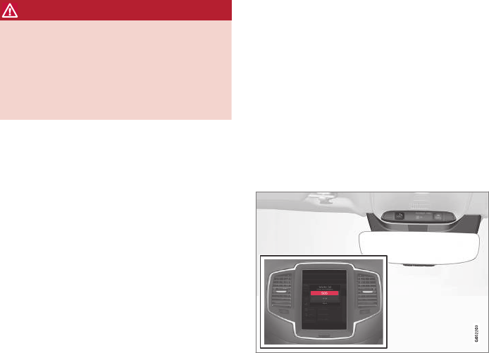
VOLVO ON CALL WITH SENSUS CONNECT *
* Option/accessory, for more information, see Introduction.
422
Volvo On Call (VOC)*
VOC is an integrated, subscription-based sys-
tem that provides emergency, roadside assis-
tance and security services.
VOC is connected to the vehicle's airbag and
alarm systems. The vehicle has an integrated
Global System for Mobile Communications
(GSM) module that handles communication
between the vehicle and the VOC customer serv-
ice center.
Availability
VOC uses the Global Navigation Satellite System
(GNSS) to locate the vehicle and its integrated
GSM module to enable communication with the
VOC customer service center and the VOC
mobile app.
From the time that the remote key has been
removed from the vehicle, VOC's functions
remain available for 5 full days and subsequently
once an hour for the following 17 days. After
three weeks have elapsed, the system will remain
switched off until the engine is started.
WARNING
The system can only function in areas where
there is adequate cellular network coverage.
Just as in the case of cell phones, atmos-
pheric disturbances or areas with relatively
few GSM transmitters can make it impossible
for VOC to make a connection, for example, in
rural areas.
Subscriptions
A free, limited-time trial subscription is initiated
when the vehicle is purchased and VOC is acti-
vated. The subscription can be extended by con-
tacting your Volvo retailer.
Information on the Internet
For additional information about Volvo On Call, go
to:
support.volvocars.com
Related information
•Volvo On Call convenience services (p. 424)
•Volvo On Call safety services (p. 432)
•Volvo On Call security services (p. 433)
•Using Volvo On Call (p. 422)
•Volvo ID (p. 26)
Using Volvo On Call
Volvo On Call (VOC) is controlled using the but-
tons in the ceiling console and the center dis-
play.
In the event of an accident in which the seat belt
pretensioners, airbags or the inflatable curtains
have been triggered, a signal is transmitted auto-
matically to the VOC customer service center,
who send the appropriate type of assistance
(ambulance, police, etc.) to the site.
When a service is active, a symbol will appear on
the center display.
VOC buttons in the ceiling console and center display
The SOS button: emergency situations
Press and hold the SOS button for approx.
2 seconds to activate the manual alarm function.

VOLVO ON CALL WITH SENSUS CONNECT *
}}
* Option/accessory, for more information, see Introduction. 423
The ON CALL button: roadside
assistance
Press the ON CALL button for approx. 2 seconds
to activate the roadside assistance functions.
Alternative to the ON CALL button
In the center display's Phone view, tap On Call.
Select Call in the pop-up window that opens.
NOTE
The SOS button should only be used in an
emergency situation such as an accident, ill-
ness or in the event of a threat to the occu-
pants of the vehicle. Misusing this button
could result in extra charges.
The ON CALL button can be used for all of
the other VOC services, including roadside
assistance.
Canceling a call
A service call that has been initiated can be can-
celled within 10 seconds by pressing the EXIT
button on the steering wheel keypad.
Settings
Settings and selections can be made in the cen-
ter display by going to sSettings
Communication Volvo On Call. These set-
tings include activating/deactivating a subscrip-
tion, button lock, etc.
Related information
•Volvo On Call (VOC)* (p. 422)
•Volvo On Call (VOC) functions (p. 423)
•Volvo On Call manual safety service (p. 432)
•Volvo On Call roadside assistance (p. 433)
Volvo On Call (VOC) functions
The following table provides an overview of the
functions that are available from the VOC cus-
tomer service center and the mobile app.
Please note that these functions are subject to
change. For up-to-date information about the
range of Volvo On Call functions and services,
contact your Volvo retailer or go to
support.volvocars.com
Function Cus-
tomer
service
center
AppA
Automatic alarm X
Manual alarm X
Roadside assistance X X
Theft notification X X
Remote Door Unlock X X
Remote Vehicle Immobil-
izer
X
Engine remote start (ERS) X
Preconditioning (hybrid
models only)
X
Locating the vehicle X X

||
VOLVO ON CALL WITH SENSUS CONNECT *
* Option/accessory, for more information, see Introduction.
424
Function Cus-
tomer
service
center
AppA
Instrument panel informa-
tion
X
Vehicle "checkup" X
Driving logbook X
Vehicle information X
ASome of these functions may not be available for all models.
Related information
•Volvo On Call (VOC)* (p. 422)
•Volvo On Call mobile app (p. 424)
•Volvo On Call convenience services (p. 424)
•Volvo On Call safety services (p. 432)
•Volvo On Call security services (p. 433)
Volvo On Call convenience services
Convenience services are available by using the
mobile app to e.g., remote-start the engine*, etc.
As a VOC user, a mobile app is available that
enables you to have telephone contact from an
iPhone or from Windows/Android phones with
your vehicle when it is parked. With it, you can
locate the vehicle, lock it from another location,
check the fuel level and much more. Read more
about this app in the following section.
Related information
•Volvo On Call (VOC)* (p. 422)
•Volvo On Call mobile app (p. 424)
•Volvo On Call (VOC) functions (p. 423)
Volvo On Call mobile app
As a VOC user, you can download a mobile app
that enables you to have telephone contact with
your vehicle when it is parked.
Certain functions may not be available in all mod-
els.
The mobile app is updated regularly, which may
result in this information not being completely
up-to-date with respect to the functionality availa-
ble. For additional information about the app, go
to support.volvocars.com
The Volvo On Call mobile app is available for the
iPhone and for Windows/Android phones and
can be downloaded from Apple's AppStore, Win-
dows Phone Store or Google Play.
A personal Volvo ID is required in order to use
the mobile app.
For additional information about the Volvo ID, the
features it offers and how to create it, see the
article "Volvo ID".
Locating the vehicle
The vehicle's location is shown on a map and
directions to the vehicle can be provided. There is
also a digital compass to help show the owner
the right direction. When you are within approx.
100 yards/meters of the vehicle, you can activate
its horn and turn signals to help locate it.
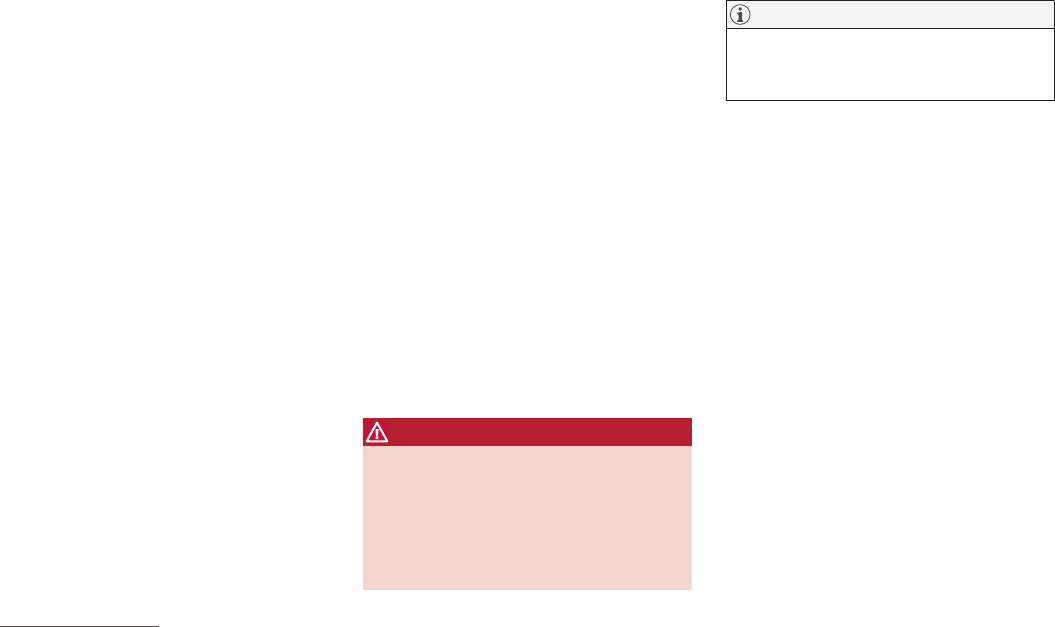
VOLVO ON CALL WITH SENSUS CONNECT *
* Option/accessory, for more information, see Introduction. 425
The vehicle's instrument panel
This function provides information such as: the
fuel level, range on the remaining fuel, average
fuel consumption, average speed and odometer/
trip odometer readings.
Vehicle "checkup"
The mobile app monitors the vehicle's condition
and provides information about bulbs and the lev-
els of brake fluid, coolant and engine oil.
Driving logbook
Detailed information about each trip made during
the past 40 days can be saved and downloaded.
All or part of this information can be exported
from the mobile app to a spreadsheet format and
sent to an email address. This is very useful for
e.g., keeping track of business-related driving.
This function can be deactivated, in which case
the vehicle will not transmit logbook information
at the end of each trip.
Vehicle information
Basic information such as model, license plate
number and VIN number are readily accessible.
Theft notification
If the vehicle's alarm is triggered, the owner will
be informed via his/her cell phone.
Remote door unlock
The status of all doors and windows is provided.
The owner can lock/unlock the vehicle from
another location but for security reasons, the
app's password is always required before the
vehicle can be unlocked.
Engine remote start (ERS)*1
ERS makes it possible to remotely start the
engine using the remote key to enable the cli-
mate system to cool or heat the passenger com-
partment before driving.
When the engine starts, the climate and infotain-
ment systems will restart using the same settings
as when the engine was switched off.
You can choose to let the engine run for
between 1 and 15 minutes before it automati-
cally switches off again. After 2 ERS starts, the
engine must be started in the normal way before
ERS can be used again.
WARNING
Keep the following in mind before using ERS:
•The vehicle should be in view.
•The vehicle should be unoccupied.
•The vehicle must not be parked indoors
or in an enclosed area. Exhaust fumes are
harmful to the health.
NOTE
Always observe applicable state, province
and/or local laws regarding engine idling
when using ERS.
Related information
•Volvo On Call convenience services (p. 424)
•Volvo On Call (VOC)* (p. 422)
•Volvo ID (p. 26)
•Starting the engine (p. 362)
•Volvo On Call (VOC) functions (p. 423)
1Certain models only.
VOLVO ON CALL WITH SENSUS CONNECT *
* Option/accessory, for more information, see Introduction.
426
Volvo On Call PIN code
The PIN code is used for security purposes to
help identify those persons who are authorized
to use VOC services in a specific vehicle.
The 4-digit PIN code, which was sent to you
when your Volvo retailer activated your subscrip-
tion, is used for security reasons to help identify
those persons who are authorized to use certain
VOC services such as remote door unlock or to
create an account in the mobile app.
If you have forgotten or would like to
change your PIN code
If you have forgotten your PIN code or would like
to change it (e.g., if you have purchased a previ-
ously owned Volvo with VOC), contact your Volvo
retailer or press the On Call button in your vehi-
cle. The new code will be sent to you via email.
If an incorrect PIN code has been
entered in the app multiple times
If a PIN code has been entered incorrectly
10 times in a row, the account will be frozen. In
order to use the app again, a new PIN code must
be selected and a new app account will have to
be created.
Related information
•Unlocking the vehicle from the customer
service center (p. 434)
•Volvo On Call mobile app (p. 424)
•Changing ownership of a vehicle with Volvo
On Call (p. 432)
•Volvo On Call (VOC)* (p. 422)


VOLVO ON CALL WITH SENSUS CONNECT *
* Option/accessory, for more information, see Introduction.
428
Personal information
Personal information is gathered for use with the
Volvo On Call (VOC) service.
Volvo's sales companies are responsible for pro-
cessing and storing VOC-related information.
This information is treated according to legisla-
tion and regulations pertaining to data of this
type.
Country Sales company
United States Volvo Cars of North America,
LLC
Canada Volvo Cars of Canada
Why information is gathered
Personal information is used by Volvo and its
partners to provide and develop the VOC service.
Types of personal information gathered
The primary types of personal information gath-
ered for VOC-related purposes are:
•Personal information that the customer pro-
vides in connection with the activation of the
VOC service and during other contact with
Volvo, including name, address, telephone
number, type of service and the duration of
the service.
•When information about a specific VOC-rela-
ted event is automatically transmitted from
the vehicle. A message of this type contains:
the vehicle identification number (VIN), time
when the service is used, type of service, if
airbags have been triggered, if the seat belt
tensioners have been triggered, current fuel
level, current temperature inside and outside
the vehicle, whether the doors are locked
and windows are closed and the vehicle's
last six locations, including speed and direc-
tion.
•Other information associated with the
owner/driver, such as telephone calls with
people in the vehicle, the customer service
center that provided the service and notes
made by the customer service operator.
Access to my personal information
Volvo uses sub-contractors to provide the service.
These sub-contractors work on behalf of Volvo
and may only process personal information to the
extent necessary to provide service. All sub-con-
tractors are bound by agreements requiring them
to observe strict confidentiality and to treat per-
sonal details in accordance with applicable legis-
lation.
Deleting personal information
The personal details required to provide the VOC
service are stored during the subscription period
and thereafter for as long as necessary in order
for Volvo to fulfil its obligations according to leg-
islation and other regulations. Information gener-
ated during events covered by the VOC service is
deleted three months after an event has occur-
red.
Corrections and register extracts
Private persons have the right to request correc-
tions of incorrect information and to obtain an
extract showing the personal information that has
been processed. Requests for extracts from the
register must be submitted in writing and signed
by the applicant and include name, address and
customer number. The request should be posted
to:
Volvo Cars of North America, LLC
Customer Care Center
1 Volvo Drive,
P.O. Box 914
Rockleigh, New Jersey 07647
Phone: 1-800-458-1552
Volvo Cars of Canada
National Customer Service
9130 Leslie Street, Suite 101
Richmond Hill, Ontario L4B 0B9
Phone: 1-800-663-8255
Consent to gather VOC-related
personal information
By activating a VOC subscription in accordance
with the instructions in this document, the user
agrees to the collection of VOC-related personal
information.

VOLVO ON CALL WITH SENSUS CONNECT *
* Option/accessory, for more information, see Introduction.
430
Volvo On Call availability
The map shows the areas in which VOC is avail-
able. The service is constantly being expanded;
contact your Volvo retailer for up-to-date informa-
tion.
VOLVO ON CALL WITH SENSUS CONNECT *
* Option/accessory, for more information, see Introduction. 431
However, the system can only function in areas
where there is adequate cellular network cover-
age.
Related information
•Volvo On Call (VOC)* (p. 422)
•Volvo On Call (VOC) functions (p. 423)
•Service center phone number (p. 427)
VOLVO ON CALL WITH SENSUS CONNECT *
* Option/accessory, for more information, see Introduction.
432
Changing ownership of a vehicle
with Volvo On Call
If the vehicle changes owners, the Volvo On Call
(VOC) service should be cancelled.
Cancelling the VOC service
If your vehicle changes owners, contact your
Volvo retailer to cancel the VOC service. The sub-
scription will be terminated and the service his-
tory will be erased.
When the vehicle changes owners, all personal
settings should be reset to the factory defaults,
see the owner's manual supplement.
Starting the VOC service
If you purchase a previously owned Volvo with
VOC:
The new owner should contact his/her Volvo
retailer to transfer the remaining period of the
VOC subscription. All contact information must
be updated in order for VOC to function and to
ensure that the previous owner is no longer
authorized to use VOC services in the vehicle.
The new owner will be given a 4-digit personal
code, which is used to identify him/her as being
authorized to approve certain VOC services.
Related information
•Volvo On Call (VOC)* (p. 422)
•Volvo On Call PIN code (p. 426)
•Resetting user data when the vehicle
changes owners (p. 112)
Volvo On Call manual safety service
Contact the Volvo On Call (VOC) customer
service center in emergency situations.
To contact the VOC customer service center
manually:
1. Press SOS to contact the customer service
center for help in emergency situations such
as illness, injury, a threat, etc.
2. An emergency signal is transmitted to the
VOC customer service center with informa-
tion about the vehicle's location.
3. The VOC customer service center attempts
to establish voice contact with the driver to
determine the extent of the accident and/or
the need for assistance.
If voice contact is not possible, the VOC cus-
tomer service then contacts the emergency serv-
ices for appropriate action.
Related information
•Volvo On Call safety services (p. 432)
•Volvo On Call roadside assistance (p. 433)
•Using Volvo On Call (p. 422)
Volvo On Call safety services
The Volvo On Call (VOC) manual or automatic
safety services are intended for use in emer-
gency situations.
Automatic alarm
In the event of certain types of accidents, a signal
is transmitted automatically to the VOC customer
service center, who take appropriate action
according to the information that they receive.
The following occurs if the seat belt pretension-
ers, airbags or the inflatable curtains have been
triggered:
1. A signal is transmitted automatically to the
VOC customer service center with informa-
tion about the vehicle's location and that an
airbag, etc., has been triggered.
2. The VOC customer service center attempts
to establish voice contact with the driver to
determine the extent of the accident and the
need for assistance.
3. The VOC customer service center then con-
tacts the appropriate emergency service
(police, ambulance, towing, etc.).
If voice contact is not possible, the VOC cus-
tomer service then contacts the emergency serv-
ices for appropriate action.
Manual alarm
Press SOS to contact the customer service cen-
ter for help in emergency situations, see also the
article "VOC manual safety service."
VOLVO ON CALL WITH SENSUS CONNECT *
}}
* Option/accessory, for more information, see Introduction. 433
Roadside assistance
Request help for e.g., flat tires, a discharged bat-
tery, if you have run out of fuel, etc.
Emergency number
When an emergency call has been initiated, VOC
attempts to contact the customer service center.
If this is not possible, the call will be transferred
to the emergency 911 number instead.
Related information
•Volvo On Call (VOC)* (p. 422)
•Volvo On Call manual safety service (p. 432)
•Volvo On Call roadside assistance (p. 433)
•Using Volvo On Call (p. 422)
Volvo On Call roadside assistance
Use VOC to summon help in the event of a flat
tire, an empty fuel tank, etc.
1. Press the ON CALL button for at least
2 seconds.
2. The VOC customer service center attempts
to establish voice contact with the driver to
determine the need for assistance.
Related information
•Volvo On Call (VOC)* (p. 422)
•Volvo On Call safety services (p. 432)
•Volvo On Call manual safety service (p. 432)
•Using Volvo On Call (p. 422)
Volvo On Call security services
The Volvo On Call (VOC) security services are
intended to provide assistance, for instance, if
you are locked out of your vehicle, if it has been
stolen, etc.
Volvo On Call's security services are primarily
intended to help minimize the risk of the vehicle
being stolen.
If the vehicle's normal electrical system is not
functioning properly, VOC's reserve battery pro-
vides the system with current.
Theft notification
A signal will be sent automatically to the Volvo
On Call customer service center in the event of a
break-in or theft (if the vehicle's alarm has been
triggered).
This service will be interrupted if the alarm is
turned off using one of the vehicle's remote keys.
Remote door unlock
If the vehicle's remote key has been lost or
locked in the car, the doors can be unlocked
remotely within the following 5 days with assis-
tance from the VOC customer service center
after the owner's identity has been verified by
his/her pin code.
Remote vehicle immobilizer
If the vehicle has been stolen, the owner or police
can contact the VOC customer service center to

||
VOLVO ON CALL WITH SENSUS CONNECT *
* Option/accessory, for more information, see Introduction.
434
have the vehicle's remote keys immobilized
(deactivated).
NOTE
This applies even if the vehicle has been
unlocked and started with one of its remote
keys.
After contacting the owner/police, the VOC cus-
tomer service center then deactivates the remote
keys. Once the engine has been switched off, it
can only be restarted if the owner/police has
given the VOC customer service center authori-
zation to reactivate the remote keys. Once this
authorization has been verified (using your PIN
code), the VOC customer service center will reac-
tivate the remote keys.
Related information
•Volvo On Call (VOC)* (p. 422)
•Unlocking the vehicle from the customer
service center (p. 434)
•Service center phone number (p. 427)
•Volvo On Call PIN code (p. 426)
Unlocking the vehicle from the
customer service center
The doors can be unlocked remotely with assis-
tance from the VOC customer service center.
1. Contact the VOC customer service center at
855-399-4691 (this number applies in both
the United States and Canada).
2. After confirming that the caller is the vehi-
cle's owner or other authorized person (using
your PIN code), the VOC customer service
center sends a signal to the vehicle to unlock
it.
3. The tailgate has to be opened to unlock the
other doors. Press lightly on the rubberized
pressure plate under the outer tailgate han-
dle.
NOTE
If the tailgate is not opened within the time
period set by the VOC customer service cen-
ter, it will relock.
NOTE
If the vehicle is parked in a garage or other
covered area, remote unlocking may not be
possible due to poor signal reception.
Related information
•Volvo On Call security services (p. 433)
•Volvo On Call (VOC)* (p. 422)
•Locking/unlocking the tailgate (p. 235)

NAVIGATION*
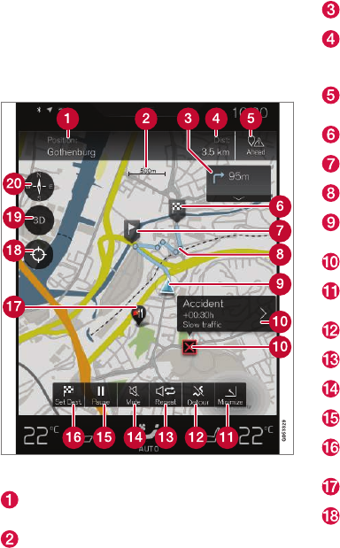
NAVIGATION*
* Option/accessory, for more information, see Introduction.
436
Sensus Navigation
Sensus Navigation enables you to set itineraries,
search for certain types of points of interest
along your route, store special destinations,
obtain traffic information en route, etc.
Sensus Navigation shows the vehicle's exact
location and if you deviate from the set route, the
system can make the necessary adjustments to
guide you to your destination.
Being familiar with the contents of this manual
will help you to fully utilize the features and func-
tions offered by Sensus Navigation.
By enabling you to reach your destination quickly
and by the most direct route, Sensus Navigation
also helps contribute to improving the environ-
ment.
Related information
•Getting started with Sensus Navigation
(p. 440)
•Buttons and information on the map (p. 436)
Buttons and information on the map
The map on the center display contains different
function buttons, symbols, types of roads and
information about the area around the vehicle
and along the selected route.
Text and symbols on the map
The vehicle's current location and a button
for viewing the itinerary
Map scale
List of guidance points in the itinerary
Remaining distance to the destination/esti-
mated time of arrival and a button for chang-
ing headers
Button for listing the itinerary's Points of
Interest (POI) and traffic information
Final destination
Intermediate destination
Guidance point
The vehicle (blue triangle) on the planned
route
Traffic problem and related information
Minimize (expanded view) or maximize (full-
screen map view)
Calculating a new route
Repeat the most recent voice guidance
Voice guidance On/Off
Pause/resume guidance
Set a final destination/intermediate destina-
tion
POI (in this case, a restaurant)
Button to reset the map to follow the vehicle
(blue triangle)

NAVIGATION*
}}
* Option/accessory, for more information, see Introduction. 437
Button for toggling between 2D/3D map
views
Compass and button for north at the top of
the map/current direction at the top of the
map
Related information
•Sensus Navigation (p. 436)
•Using the center display (p. 45)
•Center display overview (p. 28)
Common navigation system
features
The most common features of the navigation
system are described here.
•Where am I?
•Find the vehicle symbol on the map
•Direction at the top of the map/North at the
top of the map
•2D for 3D view
•Zoom
•Scroll
•Change the headers displayed
•Go back to the map view
•"Wrong" language in illustrations
Where am I?
Where is the vehicle's current location?
•Click the vehicle symbol (blue triangle) for
information directly on the map.
Find the vehicle symbol on the map
Tap the crosshairs
After scrolling/zooming, it may be difficult to find
the vehicle's location on the map. To find it:
•Tap the crosshairs: the map will be reset and
will follow the vehicle symbol.
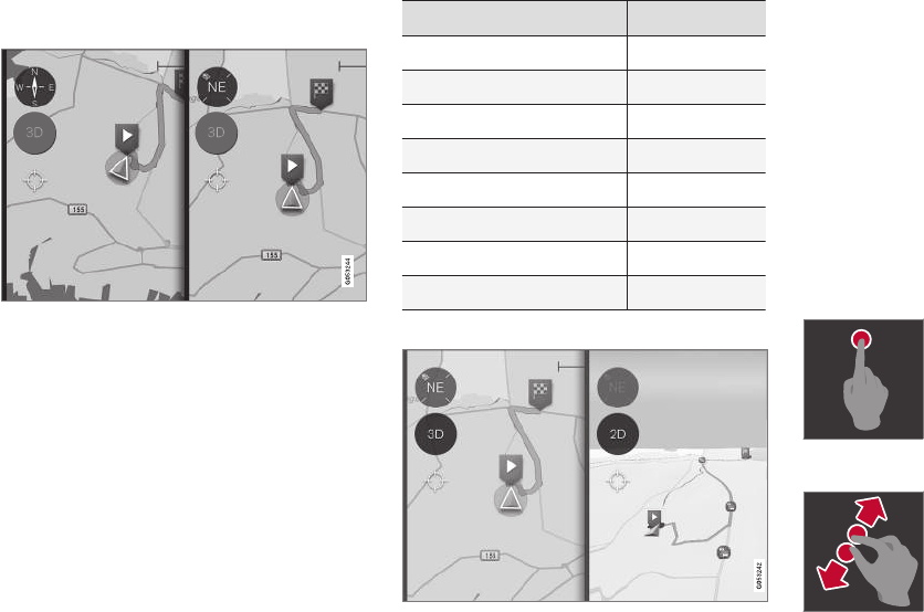
||
NAVIGATION*
* Option/accessory, for more information, see Introduction.
438
Direction at the top of the map/North at
the top of the map
Tap the compass to change the way in which the vehicle
symbol moves on the map
The driver can choose between two views:
•North will always be at the top of the map on
the center display and the vehicle symbol will
move in the current direction on the map (left
is west, right is east, etc.).
•The vehicle symbol will always move towards
the top of the center display. The map will
rotate under the vehicle symbol according to
the direction in which the vehicle turns. The
compass symbol indicates north (N) on the
map and the vehicle's direction (NE in the
illustration).
Compass symbols Direction
N North
NE Northeast
E East
SE Southeast
S South
SW Southwest
W West
NW Northwest
2D or 3D view
Tap 2D/3D to toggle between a 2D/3D map display
In 3D, the vehicle's direction is always upward on
the center display. The map will rotate under the
vehicle symbol according to the direction in which
the vehicle turns.
The compass symbol indicates north (N) on the
map and the vehicle's direction is shown at the
center of the compass.
The map scale is not shown in 3D.
2D is described in the previous section "Direction
at the top of the map/North at the top of the
map."
Zoom
Zoom in
To make the map larger:
Tap the center display twice in
quick succession with one fin-
ger.
or
"Stretch" with two fingers on
the center display.
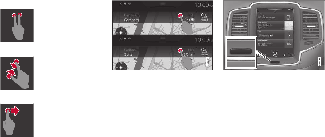
NAVIGATION*
* Option/accessory, for more information, see Introduction. 439
Zoom ut
To make the map smaller:
Tap the center display once
with two fingers.
or
"Pinch" with two fingers on the
center display.
Scroll
Place a finger on the map and
swipe in the desired direction.
Scrolling is only possible with
the map in maximized view.
Change the headers displayed
Tap to change map headings
The following headers can be displayed on the
map:
•Destination, Estimated Time of Arrival (ETA)
or Remaining Time to Arrival (RTA)
or
•Position and the distance to the destination
(Dist).
Changing headers is only possible with the map
in maximized view.
Returning to the map view
Home button below the center display
To return to the map view from another part of
the system:
1. Press the Home button.
2. If the center display shows its Home view,
tap Navigation at the top of the screen.
Related information
•Navigation in the instrument panel (p. 457)
•Sensus Navigation settings (p. 458)
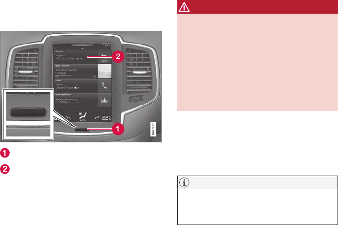
NAVIGATION*
* Option/accessory, for more information, see Introduction.
440
Getting started with Sensus
Navigation
The vehicle's electrical system (including the
navigation system) is activated automatically
when the driver's door is opened.
Navigation On/Off
Home button
"Navigation" menu line
On
If the navigation system does not show a map on
the center display, tap the Navigation line (2).
If the center display does not show the map,
press the Home button (1) and then tap
Navigation (2).
This will display a map showing the area around
the vehicle and the vehicle's current location (a
blue triangle).
WARNING
Observe the following.
•Direct all your attention to the road and
make sure that all your concentration is
on driving.
•Follow applicable traffic legislation and
drive with good judgment.
•Due to weather conditions or time of year
affecting the road conditions, some rec-
ommendations may be less reliable.
Off
While the ignition is switched on, the navigation
system is always active in the background. It
switches off automatically when the ignition is
switched off and the vehicle is locked.
NOTE
The system can be used even when the
engine is not running but will be switched off
automatically if the battery charge level is low.
Related information
•Navigation displays and controls (p. 441)
•Quick guidance to a destination (p. 441)
•Center display overview (p. 28)
•Using the center display (p. 45)
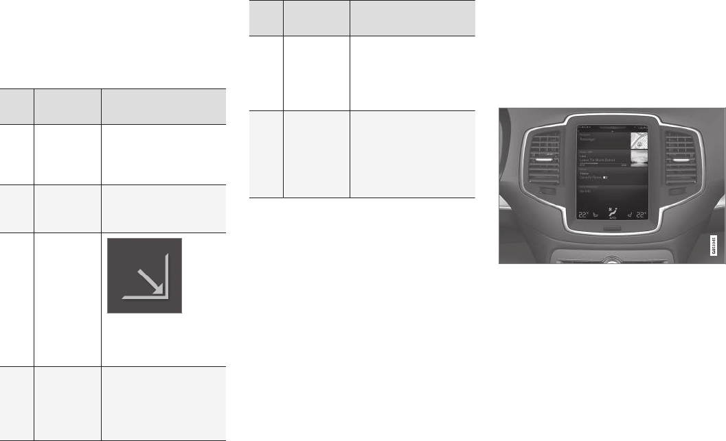
NAVIGATION*
}}
* Option/accessory, for more information, see Introduction. 441
Quick guidance to a destination
The following table provides quick information
about setting a destination and starting naviga-
tion.
Selecting a destination on the map
Step Center dis-
play/menu
Action
1 If a map is
not shown
on the cen-
ter display.
Press the Home button
under the display to
open the display's Home
view.
2 Home view
is displayed.
Tap Navigation in the
center display's upper
menu bar.
3 A map is
displayed.
If this button is dis-
played, tap it to maxi-
mize the map.
4 The map is
displayed.
Scroll to the desired
location on the map and
press and hold that
position on the screen
to set it as a destination.
Step Center dis-
play/menu
Action
5Start navi-
gation is
displayed
on the
screen.
Tap Start navigation.
6 A map
showing
the route to
your desti-
nation is
displayed.
Guidance will begin. Fol-
low the directions on the
instrument panel.
Related information
•Center display overview (p. 28)
•Using the center display (p. 45)
Navigation displays and controls
Volvo Sensus Navigation is presented on the
instrument panel and head-up display* and con-
trolled using center display on-screen buttons,
the right-side steering wheel keypad and voice
commands.
Center display
Searching for and setting destinations and mak-
ing navigation settings are done on the center
display.
If the map is not showing on the center display,
tap Navigation at the top of the center display's
Home view.
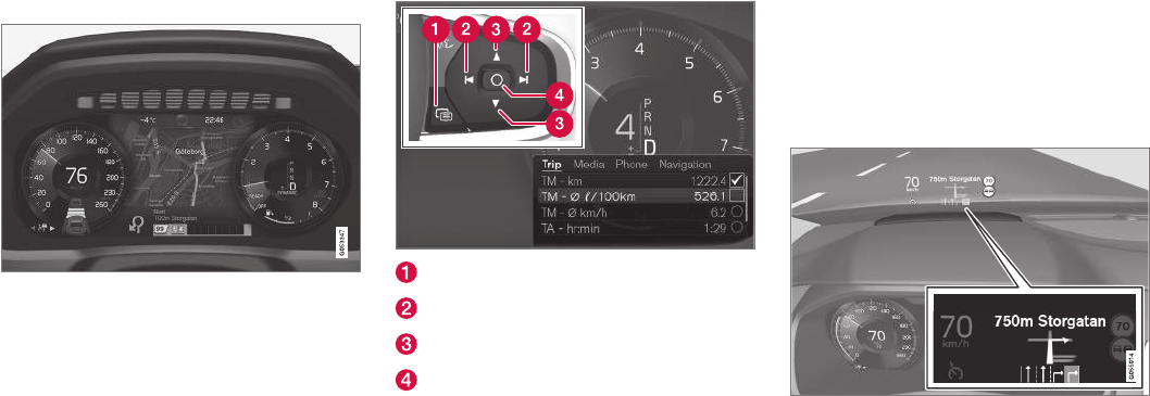
||
NAVIGATION*
* Option/accessory, for more information, see Introduction.
442
Instrument panel
The map is only shown on the 12" instrument panel
During a trip, the driver receives visual guidance
on the instrument panel and voice guidance
through the infotainment system's speakers.
Right-side steering wheel keypad and
instrument panel
Some of the navigation system's functions, such
as Take me home, are controlled from the right-
side steering wheel keypad.
Open/Close
Left/Right
Up/Down
Confirm
Opening/closing the menu
–Press Open/Close (1).
> Menus with alternatives will be opened or
closed. The menu will close automatically
after a short period or after certain selec-
tions have been made.
Navigating and making selections in a menu
1. Scroll among the alternatives using the up/
down control (3).
2. Confirm or mark a choice by pressing control
(4).
> The function will be activated and after
making certain choices, the menu will
close.
Head-up-display (HUD)*
Navigation guidance on the windshield
The driver can also get guidance and information
from the navigation system on the lower section
of the windshield.
The position of the HUD can be adjusted (see
the article "Head-up display").
Voice control
Many settings can be made using voice com-
mands.
NAVIGATION*
* Option/accessory, for more information, see Introduction. 443
Press the voice button on the
right-side steering wheel key-
pad, wait for the tone and then
say, e.g., "Drive Home."
Using voice commands is explained in greater
detail in the articles "Navigation system voice
control," "Voice control," and "Voice control set-
tings."
Related information
•Using the center display keyboard (p. 31)
•Setting a destination by entering the text of
your choice (p. 444)
•Navigation system voice commands (p. 120)
•Voice control (p. 116)
•Using voice commands (p. 117)
•Voice control settings (p. 121)
•Using the center display (p. 45)
•Center display overview (p. 28)
•Head-up display (HUD)* (p. 113)
Entering a destination
There are several different ways of choosing a
destination.
A destination can be chosen by:
•Clicking on the map
•Entering free text or coordinates
•Selecting a recently set destination
•Selecting a position marked as a favorite
from the library
•Selecting a saved destination from the library
•Selecting a point of interest (POI)
•Entering an Address: e.g., State/city/street/
intersection/house number
Select one of the alternatives and follow the
instructions given.
Destinations and intermediate
destinations (waypoints)
The first location selected will be the itinerary's
final destination.
Any other locations will be the itinerary's inter-
mediate destinations (waypoints).
An itinerary and its destinations can be edited at
any time, see also the section "Editing an itiner-
ary" in the article "Itinerary and alternate routes."
Related information
•Viewing the itinerary and alternate routes
(p. 451)
•Setting a destination by tapping the map
(p. 444)
•Setting a destination by entering the text of
your choice (p. 444)
•Setting a destination using Recent/Favor-
ites/Library (p. 446)
•Using a point of interest (POI) as a destina-
tion (p. 448)
•Setting a destination by entering an address
(p. 449)
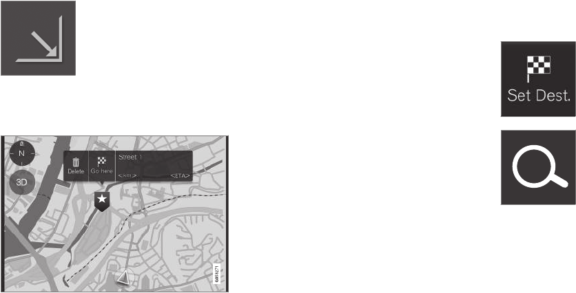
NAVIGATION*
* Option/accessory, for more information, see Introduction.
444
Setting a destination by tapping the
map
Tapping a point on the map is one way to set a
destination.
To do so:
Begin by verifying that the map
is in full-screen mode by tap-
ping the symbol (if it is dis-
played).
1. Scroll to the desired point on the map.
2. Press the point until an icon is created there
and a menu is displayed.
3. Select Go here to start guidance to that point.
Deleting the icon
Tap Delete.
Changing the icon's location
Press the icon on the map, drag it to the desired
position and release it.
Related information
•Entering a destination (p. 443)
Setting a destination by entering the
text of your choice
Entering the text of your choice is one way to set
a destination.
Entering the text of your choice
The center display's keyboard can be used to
enter most characters when searching for a des-
tination.
To display the keyboard:
1. Tap Set dest. in the lower
margin. The keyboard opens for
entering text.
2. Continue by tapping this
symbol at the top of the screen.
Enter text to search for e.g., streets, cities, map
coordinates or points of interest (POIs).
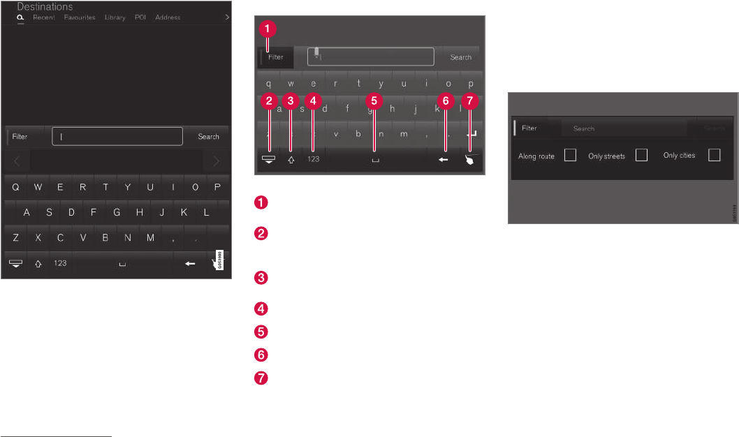
NAVIGATION*
}}
* Option/accessory, for more information, see Introduction. 445
1. Enter a word. Possible destinations meeting
your search criteria will be listed according to
their distance from the vehicle symbol on the
map (or from the center of the map if it has
been scrolled).
2. Select/mark a selection in the list. Its Info
card1 will be displayed.
3. Follow the instructions on the center display
and activate guidance to the destination.
Keyboard
Keyboard function keys
Filter: limit/filter the list of possible destina-
tions.
Hide the keys to display a longer list of pos-
sible destinations. Tap the field for entering
text to return to the keyboard.
Tap to toggle between upper and lower case
characters.
Numbers and special characters
Space bar
Delete characters to the left of the cursor.
Tap to display an area where you can "write"
text.
For additional information about using the center
display's keyboard, see the article "Using the
center display keyboard."
Filter
Several filters can be used to limit the size of the
list.
Filters
The filters available may vary:
•Along route: Lists only destinations found
along the route.
•Streets: Lists only streets/roads meeting
the search criteria.
•Cities: Lists only cities/towns meeting the
search criteria.
1See also the article "Information cards on the map."
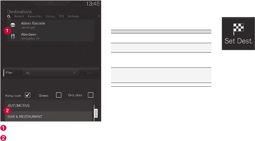
||
NAVIGATION*
* Option/accessory, for more information, see Introduction.
446
Filter for POIs
A list of available POIs is displayed at the bottom
of the screen, under the three filters.
POIs filtered from the marked category (2)
POI categories (there may also be sub-cate-
gories).
Only POIs from the marked category will be listed
and only the Along route filter can be combined
with POI.
Coordinates
A destination can also be set by entering its map
coordinates.
•For example, enter: "N 58.1234 E 12.5678"
and tap Search/.
Map coordinates can be written in different ways,
such as:
N 58.1234 E 12.5678 (with spaces)
N58.1234 E12.5678 (without spaces)
58.1234N 12.5678E (with the points on the
compass after the coordinates)
58.1234 -12.5678 (with a hyphen without the
points on the compass)
Both periods [.] and commas [,] can be used.
Related information
•Entering a destination (p. 443)
•Navigation displays and controls (p. 441)
•Using the center display keyboard (p. 31)
•Information cards on the map (p. 454)
Setting a destination using Recent/
Favorites/Library
Selecting from a list is one way of setting a des-
tination.
To display these lists:
1. Tap Set dest. in the lower
margin. A keyboard will be dis-
played with search alternatives
in the upper margin.
2. Continue by selecting one of
the lists in the upper margin:
•Recent
•Favorites
•Library
After marking an alternative, it will be added as a
destination by tapping the Start navigation or
Add as waypoint buttons.
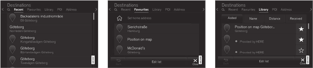
NAVIGATION*
}}
* Option/accessory, for more information, see Introduction. 447
Recent
This is a list of all searches that have been made.
Scroll through the list and select.
This menu alternative is also available in the
instrument panel and can be displayed using the
right-side steering wheel keypad (see also the
article "Navigation system displays and controls").
Favorites
This is a list of locations that have been set as
favorites from the Library. Scroll through the list
and select.
A deleted location in Favorites always remains in
the Library but the "star" will not be highlighted.
To return it to the list of Favorites, go to the
Library and tap the location's star again.
Use Set home address to program a destina-
tion that is used often. A destination set as
Home will also be also available in the instru-
ment panel and can be displayed using the right-
side steering wheel keypad (see also the article
"Navigation system displays and controls").
Use Edit to edit destinations in the list.
Library
This is a list of saved destinations and itineraries.
The most recently saved one will be at the top of
the list. Scroll through the list and select.
Tap the destination's "star" to select/deselect it
as a favorite. A selected destination will also be
shown under the heading Favorites.
A destination deleted from the Library will also
be deleted from Favorites.
The library can be sorted by:
•Added
•Name
•Distance
•Received: this is a filter
With Received, destinations sent to the vehicle
using the Send to Car function can be filtered.
New, unread destinations have a BLUE marker
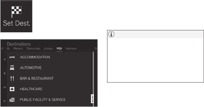
||
NAVIGATION*
* Option/accessory, for more information, see Introduction.
448
that disappears when they have been read. See
the article "Saving a destination with send-to-
car" for additional information.
Use Edit to edit the respective destinations with
respect to Name, Location, Internet address and
Phone number (max. 3 phone numbers per desti-
nation).
Related information
•Saving a destination with Send to Car
(p. 450)
•Navigation displays and controls (p. 441)
•Entering a destination (p. 443)
Using a point of interest (POI) as a
destination
Selecting a point of interest (POI) is one way of
setting a destination.
1. Tap Set dest. in the lower
margin. A keyboard will be dis-
played with search alternatives
in the upper margin.
2. Continue by selecting a POI
from the upper margin.
Examples of POIs
Many POIs (e.g., restaurants) have sub-categories
(e.g., Chinese restaurants).
Proposed POIs are listed according to their dis-
tance to the vehicle symbol or the center of the
map (if it has been scrolled).
See the article "Map settings" for information
about selecting the POIs to be displayed on the
map. This will show the selected POIs available in
the area. This setting does not affect searches
for POIs to be used as destinations (even ones
that have not been selected for display can be
used as a destination).
Certain POIs will only appear if the map scale is
greater than 1 mi. (1 km).
NOTE
•The appearance, number and variations
of POIs vary from market to market.
•Some symbols may be added/deleted
when the navigation system's software is
updated. The POIs available for the cur-
rent map system can found in the menu
system.
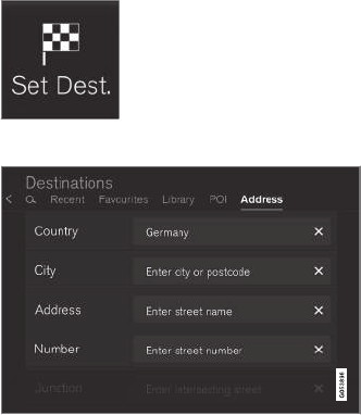
NAVIGATION*
* Option/accessory, for more information, see Introduction. 449
Filters
When an itinerary has been activated and a POI
category has been selected, a filter will be availa-
ble to limit the search list to only show POIs
along the route. This list can then be sorted by
name or distance.
•Along route: only shows POIs along the
route.
With filters activated, the list can be sorted by
Name or Distance.
Proposed POIs are listed according to their dis-
tance from the vehicle symbol on the map or
from the center of the map if it has been scrolled.
Related information
•Entering a destination (p. 443)
•Map settings (p. 459)
Setting a destination by entering an
address
Entering an address is one way to set a destina-
tion.
Tap Set dest. in the lower
margin. A keyboard will be dis-
played with search alternatives
in the upper margin.
2. Continue by selecting an
Address from the upper mar-
gin. Additional search fields will be added.
Examples of search fields
The following search alternatives may vary some-
what from market to market. Only those available
for your market will be shown in the center dis-
play.
Select any of the following alternatives and enter
text using the center display's keyboard:
•Country/State/Province
•City/Territory/Zip code
•Address
•Number
•Junction
Related information
•Entering a destination (p. 443)
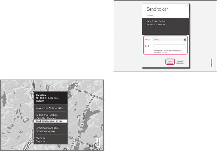
NAVIGATION*
* Option/accessory, for more information, see Introduction.
450
Saving a destination with Send to
Car
Using the Send to Car feature is one way to
save a destination.
Send to Car is a function that makes it possible
to add a destination/location to the navigation
system from a computer.
Send to Car can also be done from a cell phone
using Volvo's Volvo On Call (VOC) service.
VOC can also be used to send a destination from
the VOC customer service center to the vehicle.
Right-click the desired location and select Send this
location to car
Enter the vehicle's VIN number or Volvo ID and select
Send
1. Go to the Internet site here.com: a map serv-
ice will open.
2. Right-click the desired location.
3. Select Send this location to car.
4. Enter the vehicle's VIN number or Volvo ID.
5. Select Send: the location will be sent to the
vehicle's library (list of destinations), where it
will be indicated by a blue marker.
The driver will then be alerted to this by a symbol
that illuminates in the center display indicating
that a destination/location has been sent to the
vehicle. Tap the symbol and a card will open
showing information and possible alternatives.
Please note that the procedure shown here is
just an example from one of many map service
providers. See the Volvo Cars support site
(support.volvocars.com) for more information
about the Send to Car function.
Related information
•Volvo On Call (VOC)* (p. 422)
•Internet connected vehicle (p. 409)
•Setting a destination using Recent/Favor-
ites/Library (p. 446)
•Entering a destination (p. 443)
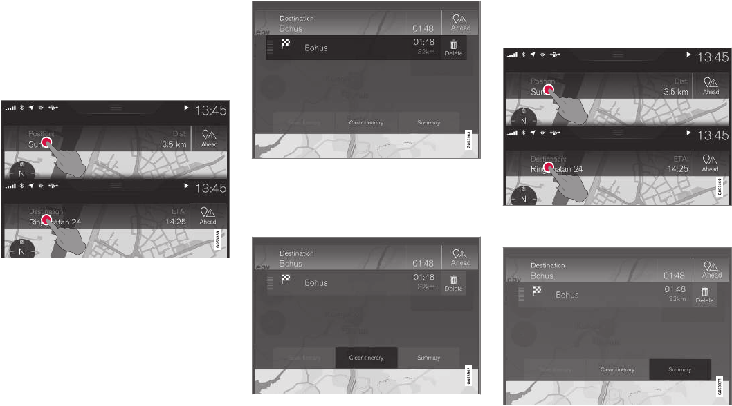
NAVIGATION*
}}
* Option/accessory, for more information, see Introduction. 451
Viewing the itinerary and alternate
routes
During guidance, it is possible to view the itiner-
ary or see if alternate routes are available.
Viewing the itinerary
To view/display the itinerary:
Tap Position: or Destination: to display the cur-
rent itinerary.
Editing an itinerary
An itinerary can be edited:
Select a line in the itinerary and follow the instructions
provided
Deleting an itinerary
The entire itinerary or intermediate destinations
(waypoints) can be deleted:
Select a particular waypoint or Clear itinerary and con-
firm the choice
Viewing alternate routes
The driver can check for alternate routes at any
time while guidance is underway. To do so:
1. Tap Position: or Destination: to display the
current itinerary.
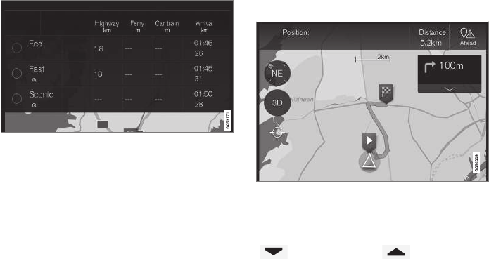
||
NAVIGATION*
* Option/accessory, for more information, see Introduction.
452
2. Tap Alternative
routes to view alternate routes (if available)
for the remainder of the itinerary.
3. Select one of the following:
•Fast
•Eco
•Scenic
4. Tap the map. The updated itinerary will be
shown on the map and guidance will resume.
See also the section "Alternate routes" in the
article "Route settings."
Related information
•Guidance points in the itinerary (p. 452)
•Choosing a detour (p. 455)
•Information cards on the map (p. 454)
•Route settings (p. 461)
Guidance points in the itinerary
A list of coming guidance points helps the driver
prepare for the next turn, etc. by e.g., getting into
the correct traffic lane.
Guidance points in an itinerary
A list of coming guidance points will appear on
the map when the itinerary is activated. The list
can be expanded by tapping the down-arrow
(). Tap the up-arrow ( ) to minimize.
The next guidance point is always at the top of
the list.
Tapping any of the guidance points in the list will
scroll the map to the related position. Subse-
quently tapping the map's crosshairs (below the
2D/3D button) will return you to the map guid-
ance view where the map shows the vehicle's
current location.
Related information
•Choosing a detour (p. 455)
•Viewing the itinerary and alternate routes
(p. 451)
•Information cards on the map (p. 454)
•Route settings (p. 461)

NAVIGATION*
}}
* Option/accessory, for more information, see Introduction. 453
POIs along the route
A list of points of interest (POIs) along the route
can be displayed.
1. Tap Ahead
2. Then tap "POI" for information about POIs along the
route
A list will show the current POI categories e.g.,
near an exit or service area
1. Select the desired category to open a list,
sometimes with sub-categories.
2. Continue to "zoom in" until a particular POI
can be selected.
3. Mark a POI in the list. Its information card will
be displayed.
4. Select one of the card's alternatives and fol-
low the instructions.
POI suggestions will be listed based on their dis-
tance on the map from the vehicle symbol or the
center of the map (if it has been scrolled). The
POI at the top of the list is closest to the vehicle.
Related information
•Using a point of interest (POI) as a destina-
tion (p. 448)
Traffic problems along the route
A list of traffic problems along your route can be
displayed.
1. Tap Ahead.
2. Then tap Traffic for information about traffic problems
along the route
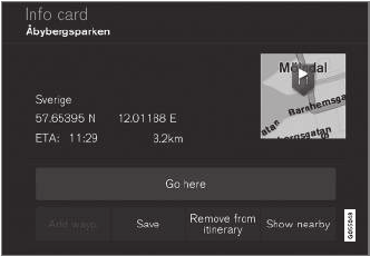
||
NAVIGATION*
* Option/accessory, for more information, see Introduction.
454
For information about a specific traffic tie-up:
•Select it in the list to get specific information.
Use the selection Avoid to be rerouted to an
alternate route to your destination.
Related information
•Traffic information (p. 456)
•Traffic information settings (p. 463)
Information cards on the map
Each icon on the map for a destination, inter-
mediate destination (waypoint), favorite, POI,
traffic problem, etc., has an information card that
can be opened by tapping the icon.
Opening an icon's Info card gives the driver up-
to-date information about the respective icons.
Information and possible alternatives vary
depending on the type of icon.
Example of an information card for a POI
In this example of a highlighted POI, the driver
can select e.g.,:
•Start navigation: save the POI's location as
a destination
•Add as waypoint: save the POI's location as
an intermediate destination
•Save: save the location in the Library. See
also the article "Entering a destination using
Recent/Favorites/Library."
Related information
•Viewing the itinerary and alternate routes
(p. 451)
•Guidance points in the itinerary (p. 452)
•Choosing a detour (p. 455)
•Route settings (p. 461)
•Setting a destination using Recent/Favor-
ites/Library (p. 446)
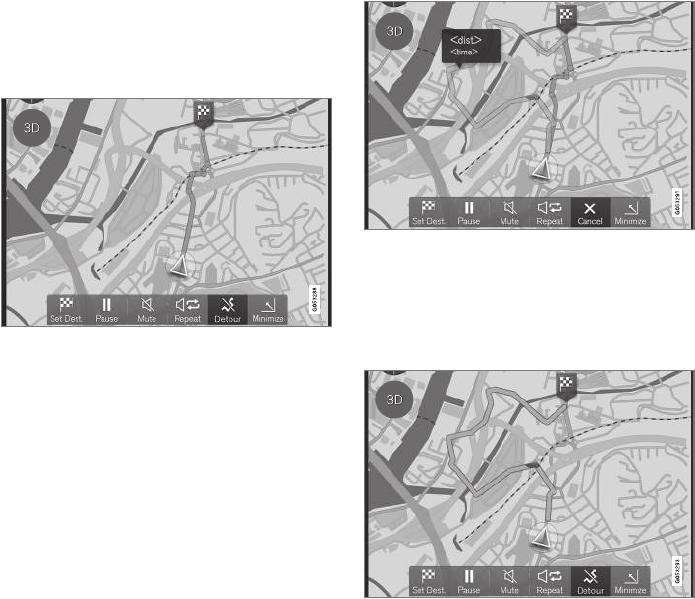
NAVIGATION*
* Option/accessory, for more information, see Introduction. 455
Choosing a detour
Select Detour to avoid the next section of a
route if e.g., a road is closed.
Detours
Detour button
1. Tap Detour: information about an alternate
route will be displayed on the map (the alter-
nate route's distance, estimated travel time,
etc.).
Normally, only short detours are proposed to
take you quickly back to your itinerary's origi-
nal route if possible.
Detour and information about it
2. To accept the proposal, tap the sign with
information about the detour
To reject the proposal, tap the X button
(Cancel). Guidance will continue along the
current route.
Detour activated
3. After a proposal has been accepted, guid-
ance will resume, using the detour as the
new route.
As an alternative to Detour, select another route
and leave your itinerary's current route. The sys-
tem will update the route automatically and con-
tinue guidance to your destination along the most
suitable route.
See also the article "Viewing the itinerary and
alternate routes."
Related information
•Route settings (p. 461)
•Viewing the itinerary and alternate routes
(p. 451)
•Information cards on the map (p. 454)
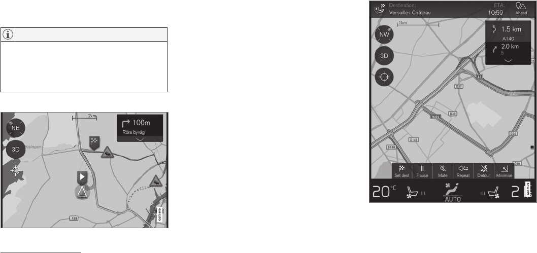
NAVIGATION*
* Option/accessory, for more information, see Introduction.
456
Traffic information4
The navigation system constantly receives traffic
messages that are broadcast by local radio sta-
tions.
See the article "Traffic settings" for the traffic-
related settings available to the driver.
NOTE
Traffic information is not available in all
areas/states/provinces.
The transmission range for traffic information
is being increased continuously.
Directly on the map
Example of traffic information
Traffic jams, road construction areas, accidents,
etc. are shown on the map in the form of various
symbols.
In cases of major traffic disruptions, their extent
is shown on the map as RED lines along the side
of the road (in e.g., road construction areas). This
line will also indicate the direction (there will be
lines on both sides of the road if both sides are
affected).
•Tap the symbol for additional information
about the traffic problem.
If the traffic problem affects your chosen route,
you can opt to select Avoid to prompt the system
to find an alternate route.
Related information
•Traffic information settings (p. 463)
•Traffic problems along the route (p. 453)
Enhanced traffic information (RTTI)
When the vehicle is connected to the Internet,
enhanced traffic information (RTTI6) may be
available7.
Generic illustration
Information about current traffic situations is
gathered continuously from mobile apps, public
4Not available in all markets.
6Real Time Traffic Information
7Certain markets only.
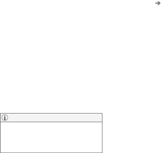
NAVIGATION*
}}
* Option/accessory, for more information, see Introduction. 457
service sources and GPS data from the vehicle.
When a vehicle requests information about the
flow of traffic, anonymous data about the traffic
situation in the vicinity of the vehicle is provided,
which helps enable RTTI to function. This data is
only transmitted if RTTI is activated.
Current traffic information is shown for highways/
freeways, major roads, secondary roads and in
some cases for urban routes.
The amount of traffic information shown on the
map depends on the distance from the vehicle,
but not farther than approx. 65 miles (100 km)
from the vehicle's current location.
Text and symbols on the map are displayed in the
usual way and the traffic flow shows how fast
traffic is moving on a given road compared to the
posted speed limit. Traffic information is shown in
both directions on a road with a colored line in
each direction:
•Green: traffic flowing smoothly.
•Yellow: slow-moving traffic.
•Red: traffic tie-up/accident.
NOTE
Traffic information is not available in all
areas/states/provinces.
The transmission range for traffic information
is being increased continuously.
Activating/deactivating
The vehicle must be connected to the Internet in
order to use RTTI.
1. Tap Settings in the center display's Top
view.
2. Tap Navigation Traffic and select a set-
ting for connected traffic information: Use
RTTI when an internet connection is
available/Use online traffic information.
•Check the box: RTTI is activated and
replaces the normal traffic information
function.
•Deselect the box: RTTI will be deactivated
and the normal traffic information function
will be activated.
If the vehicle's Internet connection is lost while
RTTI is activated, the normal traffic information
will activate automatically. If the Internet connec-
tion is re-established, RTTI will reactivate.
Related information
•Connecting to the Internet (p. 410)
•Traffic information (p. 456)
Navigation in the instrument panel
An activated route will automatically be displayed
in the instrument panel.
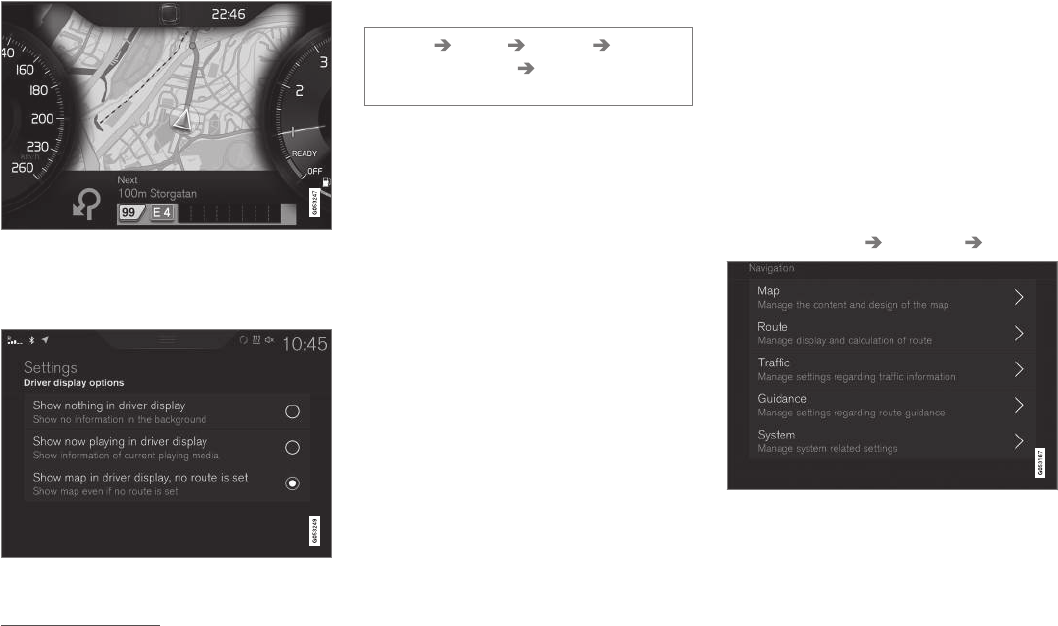
||
NAVIGATION*
* Option/accessory, for more information, see Introduction.
458
Instrument panel (driver display)9
The driver can opt to get navigation information
in the instrument panel even if no route/itinerary
has been set.
Activating/deactivating map display in the instrument
panel
Path:
Settings My Car Displays Driver
Display Center Area Driver Display
Options
•Mark the alternative Show Navigation.
Related information
•Sensus Navigation settings (p. 458)
•Navigation displays and controls (p. 441)
Sensus Navigation settings
These settings affect e.g., the way in which
routes are selected and how information is dis-
played.
Navigation can be presented in various ways and
the user can set different parameters to person-
alize the way in which the map is displayed on
the screen.
To access the navigation settings:
1. Pull down the center display's Top view.
2. Select Settings Navigation Route.
The following types of settings are available:
9The map is only shown in the 12" instrument panel.
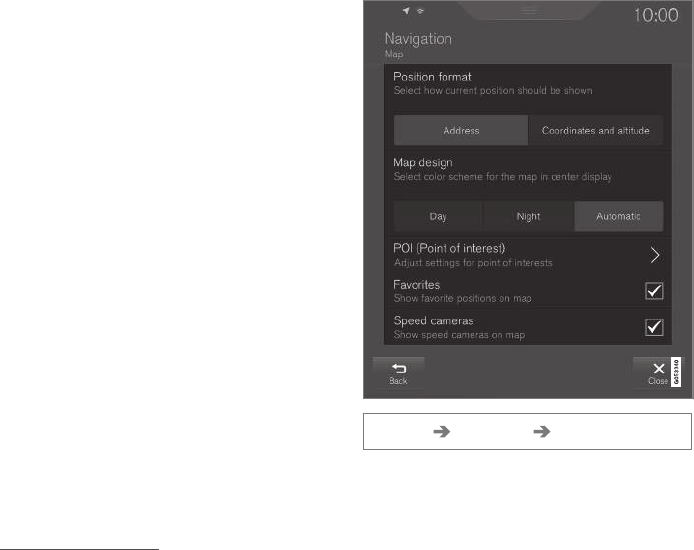
NAVIGATION*
}}
* Option/accessory, for more information, see Introduction. 459
•Map: settings for the content and appear-
ance of the map
•Route: settings for the way in which routes
are calculated and displayed
•Traffic: settings for traffic information
•Guidance: settings for guidance
•System: information about map and soft-
ware updates
Related information
•Map settings (p. 459)
•Navigation in the instrument panel (p. 457)
•Route settings (p. 461)
•Traffic information settings (p. 463)
•Guidance settings (p. 464)
•System settings (p. 464)
•Center display overview (p. 28)
Map settings
These settings are used to determine how the
map will be displayed on the screen.
Settings Navigation Map
Alternatives:
•Position Format
•Map Design
•POI
•Favorites
•Speed Cameras11
11 Not available in all markets.

||
NAVIGATION*
* Option/accessory, for more information, see Introduction.
460
Location format
Select to display the current location by address
or by coordinates:
•Address
•Coordinates and Altitude
The following illustration shows both alternatives:
Map design
Select map background lighting:
•Day: bright colors
•Night: Dark colors for better night vision
•Auto: the system will shift between Day and
Night based on the ambient light in the pas-
senger compartment.
POI
Select the POIs to be displayed on the maps.
Each main category has two alternatives: every
POI category will be displayed or...
POI main categories
...open the category by tapping the ">" symbol
and selecting the sub-categories to be displayed.
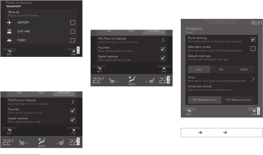
NAVIGATION*
}}
* Option/accessory, for more information, see Introduction. 461
POI sub-categories
•Mark the POI categories to be displayed on
the map. Exit the menu by tapping Back or
Close.
See also the article "POI as destination."
Favorites
Choose to display Favorites on the map:
•Yes/No
See also the article "Entering a destination using
Recent/Favorites/Library."
Speed cameras11
Choose to display speed cameras on the map:
•Yes/No
Related information
•Sensus Navigation settings (p. 458)
•Setting a destination using Recent/Favor-
ites/Library (p. 446)
•Using a point of interest (POI) as a destina-
tion (p. 448)
Route settings
The following settings determine how a route will
be calculated.
Path:
Settings Navigation Route
11 Not available in all markets.
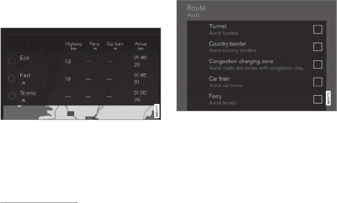
||
NAVIGATION*
* Option/accessory, for more information, see Introduction.
462
Possible settings:
•Route Learning
•Alternative Routes
•Default Route Type
•Avoid
•Arrival Time Format
Route learning
Allow data to be collected to optimize route cal-
culations:
•Yes/No
Alternative routes
Show 3 alternative routes before guidance
begins:
•Yes/No
Default route type
Select the default type of route to be used:
•Fast
•Eco
•Scenic
This setting can also be changed while driving.
See also the article "Itinerary and alternate
route."
Avoid
Mark the types of roads to be automatically avoi-
ded when a route is calculated:
•Tunnel
•International Border12
•Congestion Charge Zone
•Car train
•Ferry
•Highway
•Toll Roads
Arrival time format
Choose among:
•ETA (Estimated Time of Arrival)
•RTA (Remaining Time to Arrival)
Related information
•Sensus Navigation settings (p. 458)
•Viewing the itinerary and alternate routes
(p. 451)
12 Not available in all markets.
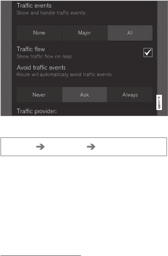
NAVIGATION*
* Option/accessory, for more information, see Introduction. 463
Traffic information settings13
These options determine how traffic information
is presented.
Path:
Settings Navigation Traffic
•Traffic Events
•Free Flowing Traffic
•Avoid Traffic Events
•Traffic Provider: %s
Traffic events
Filter the type of traffic information to be dis-
played on the map and determine how a route is
to be calculated. The alternatives are:
•None
•Major
•All
Free flowing traffic
Select if free-flowing traffic is to be displayed on
the map (shown as green lines). Select:
•Yes/No
Orange or red lines are set according to the cur-
rent traffic situation and cannot be avoided.
Avoid traffic events
Select to allow the system to automatically avoid
traffic problems along the route. Select:
•Never
•Ask
•Always
When calculating a route, the system will take
these settings into account. The driver will have
to "confirm" events that occur during a trip.
Traffic provider:
Set the source of traffic information351013
Related information
•Sensus Navigation settings (p. 458)
•Traffic problems along the route (p. 453)
•Traffic information (p. 456)
13 Not available in all markets.
3Not available in all markets.
5Not available in all markets.
10 Not available in all markets.
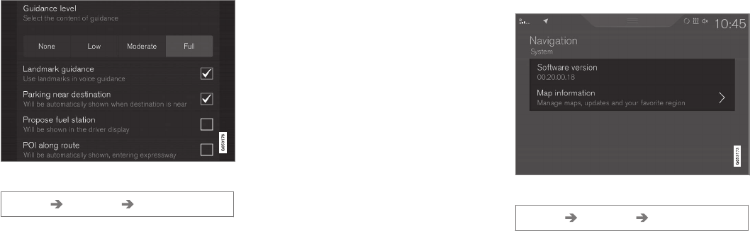
NAVIGATION*
* Option/accessory, for more information, see Introduction.
464
Guidance settings
This section lists guidance settings.
Path:
Settings Navigation Guidance
Selections:
•Voice Guidance
•POI Along Route
Voice guidance level
Set the amount of guidance information provided:
•None: no automatic guidance but guidance
can be requested manually once.
•Low: one message per guidance point.
•Moderate: up to three messages per guid-
ance point, with limited information.
•Full: up to four messages per guidance
point, with all available information provided.
POI along the route
Select to display POIs along the route.
•Yes/No
A list will be displayed automatically when driving
on a highway. See also the article "POIs along
the route."
Related information
•Sensus Navigation settings (p. 458)
•POIs along the route (p. 453)
System settings
This article describes settings for the navigation
system software and map versions.
Path:
Settings Navigation System
Software version
•Base Map Version_ e.g., 00.20.00.18
See also the article "Updating map data with
MapCare".
Map version
•Map Information: information about maps,
updates and your favorite regions.
Related information
•Sensus Navigation settings (p. 458)
•Map updates with MapCare (p. 465)

NAVIGATION*
}}
* Option/accessory, for more information, see Introduction. 465
Map updates with MapCare
Volvo Sensus Navigation remote updates can be
done directly to the vehicle through an cell
phone Internet connection or from a computer
with a USB flash drive.
General update information
The system's maps are divided into a number of
fixed regions. When updates are done, it is not
necessary to update all of the regions at the
same time but instead can be done for a specific
region or several regions.
One or several regions can be updated from the
vehicle's Internet connection. However, for major
updates, a computer and a USB flash drive are
recommended.
If an itinerary covers several regions, they should
all have the same version number to enable the
system to calculate the best route to the destina-
tion(s).
Updating the map structure
Changing the map structure may sometimes be
necessary, e.g., if a region is added or if a large
region is divided into smaller ones. If this is the
case, normal updates may not be possible and a
message will be displayed explaining what has
happened.
In this situation, the entire map must be reinstal-
led from a USB flash drive. For additional infor-
mation, go to support.volvocars.com or contact a
Volvo retailer.
Updating navigation system software
In addition to the maps, the system's software is
being steadily developed and has to be updated
occasionally. This may mean that newly downloa-
ded map information may not be supported by
the navigation system's software. If this happens,
a message will be displayed indicating that the
software needs to be updated. This can be done
by a Volvo retailer or from a USB flash drive.
See the section "Software version" in the article
"System settings."
Updates from the vehicle's Internet
connection or from a USB flash drive
For detailed information, see the articles "Remote
map updates" and "Map updates from the com-
puter with a USB flash drive."
FAQs
Question Answer
Can the
map data-
base be
changed,
e.g., from
Europe to
North Amer-
ica?
Yes, with certain exceptions.
Contact a Volvo retailer for up-
to-date information.
How long
do map
updates
take?
This depends on the size of the
file(s) and the speed of the
Internet connection. Informa-
tion about the size of the
update (in Mb) will be dis-
played.
How big is
an update?
This varies from market to mar-
ket. Go to
support.volvocars.com or con-
sult a Volvo retailer.
Updating
has not
worked.
What should
I do?
Try the Volvo Cars support site
(support.volvocars.com) or con-
tact a Volvo retailer.
Related information
•Remote map updates (p. 466)
•Map updates from a computer with a USB
flash drive (p. 467)
NAVIGATION*
* Option/accessory, for more information, see Introduction.
466
•Sensus Navigation troubleshooting (p. 471)
•Copyright (p. 471)
•Navigation license agreements (p. 469)
•System updates (p. 498)
•Internet connected vehicle (p. 409)
•Connecting to the Internet (p. 410)
•System settings (p. 464)
Remote map updates
Some preparation is necessary before a remote
update can be made through a cell phone Inter-
net connection.
Preparations
Remote update procedure
Internet connection
The vehicle has to be connected to the Internet
using Bluetooth, Wi-Fi, through a cable con-
nected to the USB socket or using the vehicle's
integrated modem. A symbol showing the con-
nection's status can be seen in the center dis-
play's status bar.
See also the articles "Internet connected vehicle"
and "Connecting to the Internet."
Downloading maps from the Internet
Downloads are done using the
Remote update service in
the center display's App view.
1. From the center display's Home view, swipe
from right to left to access App view.
2. Open the Remote update service app.
> A download app will start and an icon in
the Maps button will show the number of
available updates.
3. Tap Maps to display a list of available
updates.
4. Mark the desired region. Tap the down-arrow
for information about the current version of
the map data or tap Install to see if a newer
version is available.
For additional information, see the Volvo Cars
support site (support.volvocars.com) or contact a
Volvo retailer.
Related information
•Map updates with MapCare (p. 465)
•Internet connected vehicle (p. 409)
•Connecting to the Internet (p. 410)
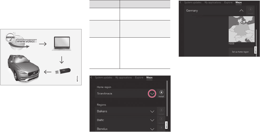
NAVIGATION*
}}
* Option/accessory, for more information, see Introduction. 467
Map updates from a computer with
a USB flash drive
Some preparation is necessary before a USB
map update can be carried out.
Preparations
Computer/USB update procedure
USB flash drive
For use in updates, a USB flash drive has to meet
the following requirements:
Parameter Requirement
USB standard
(1.0/2.0/3.0): At least 2.0
File system
(Ext2/NTFS/
FAT32):
FAT32
Capacity
(8/16/32/64
GB):
The file size varies from
market to market. See the
file size under "Detailed
information" for your market
at the Volvo Cars support
site (support.volvocars.com).
Current map version
Generic example of map regions. Tap the down-arrow
for additional information
Generic example of a region. Tap Set as home region to
set it as a home region
Begin by determining the map version before
beginning a download. To do so:
1. From the center display's Home view, swipe
from right to left to access App view.
2. Select the Remote update service app.
3. Mark a region and tap the down-arrow for
information about the current map version or
tap Install to see if there is a newer version.
Downloading maps from the Internet to
a USB flash drive
From a computer with an Internet connection,
connect to the Volvo Cars support site

||
NAVIGATION*
* Option/accessory, for more information, see Introduction.
468
(support.volvocars.com) and follow the instruc-
tions on the screen.
1. Tap "Detailed information" for the region to
be updated.
2. Information about the latest maps for the
region will be displayed. Verify that it is newer
than the version in the vehicle.
3. Connect a USB flash drive to the computer
and download the update to the USB drive.
The amount of time for the download varies
according to the size of the file and the speed of
the Internet connection.
Transferring the updated maps from
the USB drive to the vehicle
General information
This transfer may take between 30–60 minutes
depending on the file size. This must be done
with the navigation and infotainment systems
activated.
If the engine is not running, it may be necessary
to connect a battery charger to avoid discharging
the battery. An update can also be done while
driving.
During a complete map download, certain info-
tainment system functions may not be available
or have limited functionality:
•Navigation
•Voice commands
•Information/media stored on the vehicle's
hard drive
Updating
1. Activate the navigation system (see the pre-
vious section "Current map version").
2. Connect the USB drive to the vehicle's USB
socket in the tunnel console.
3. The navigation system will automatically
detect any available updates. The update's
progress will be displayed on the screen as
%.
The driver must tap Confirm to start the
update or Cancel to interrupt it.
4. Tap Confirm. The update will begin and pro-
gress information will be shown on the cen-
ter display.
5. The center display will indicate when the
update has been completed. Remove the
USB drive from the socket.
6. Verify that the correct map information has
been transferred by repeating the procedure
in "Current map version."
Interruptions
What happens if... Answer
...the infotainment
system is turned off
while an update is in
progress?
The process will pause
and will continue auto-
matically when the
system is reactivated.
...the USB flash drive
is removed from the
USB socket while an
update is in pro-
gress?
The process will pause
and will continue auto-
matically when the
USB drive is recon-
nected to the USB
socket.
If an update is interrupted, an explanatory text will
always appear on the center display.
For additional information, see the Volvo Cars
support site (support.volvocars.com) or contact a
Volvo retailer.
Related information
•Map updates with MapCare (p. 465)
NAVIGATION*
}}
* Option/accessory, for more information, see Introduction. 469
Navigation license agreements
The following is information for the end-user of
the Sensus Navigation system.
END USER LICENSE AGREEMENT FOR
DISTRIBUTION BY HERE
FOR THE AMERICAS/ASIA PACIFIC
END-USER TERMS
The content provided (“Data”) is licensed, not
sold. By opening this package, or installing,
copying, or otherwise using the Data, you agree
to be bound by the terms of this agreement. If
you do not agree to the terms of this agreement,
you are not permitted to install, copy, use, resell
or transfer the Data. If you wish to reject the
terms of this agreement, and have not installed,
copied, or used the Data, you must contact your
retailer or HERE North America, LLC (as defined
below) within thirty (30) days of purchase for a
refund of your purchase price. To contact HERE,
please visit www.here.com. The Data is provided
for your personal, internal use only and may not
be resold. It is protected by copyright, and is
subject to the following terms (this “End User
License Agreement”) and conditions which are
agreed to by you, on the one hand, and HERE
and its licensors (including their licensors and
suppliers) on the other hand. For purposes of
these terms, “HERE” shall mean
(a) HERE North America, LLC with respect to
Data for the Americas and/or the Asia Pacific
region and (b) HERE Europe B.V. for Data for
Europe, the Middle East and/or Africa. The Data
includes certain information and related content
provided under license to HERE from third
parties and is subject to the applicable supplier
terms and copyright notices set forth at the
following URL:
here.com/supplierterms
TERMS AND CONDITIONS
License Limitations on Use: You agree that
your li¬cense to use this Data is limited to and
conditioned on use for solely personal,
noncommercial purposes, and not for service
bureau, timesharing or other similar purposes.
Except as otherwise set forth herein, you agree
not to otherwise reproduce, copy, modify,
decompile, disassemble or reverse engineer any
portion of this Data, and may not transfer or
distribute it in any form, for any purpose, except
to the extent permitted by mandatory laws.
License Limitations on Transfer: Your limited
license does not allow transfer or resale of the
Data, except on the condition that you may
transfer the Data and all accompanying materials
on a permanent basis if: (a) you retain no copies
of the Data; (b) the recipient agrees to the terms
of this End User License Agreement; and (c) you
transfer the Data in the exact same form as you
purchased it by physically transferring the original
media (e.g., the CDROM or DVD you purchased),
all original packaging, all Manuals and other
documentation. Specifically, Multidisc sets may
only be transferred or sold as a complete set as
provided to you and not as a subset thereof.
Additional License Limitations: Except where
you have been specifically licensed to do so by
HERE in a separate written agreement, and
without limiting the preceding paragraph, your
license is conditioned on use of the Data as
prescribed in this agreement, and you may not (a)
use this Data with any products, systems, or
applications installed or otherwise connected to
or in communication with vehicles capable of
vehicle navigation, positioning, dispatch, real time
route guidance, fleet management or similar
applications; or (b) with, or in communication
with, including without limitation, cellular phones,
palmtop and handheld computers, pagers, and
personal digital assistants or PDAs.
Warning: This Data may contain inaccurate or
incom¬plete information due to the passage of
time, changing circumstances, sources used and
the nature of collecting comprehensive
geographic Data, any of which may lead to
incorrect results.
No Warranty: This Data is provided to you “as is”,
and you agree to use it at your own risk. HERE
and its licensors (and their licensors and
suppliers) make no guarantees, representations
or warranties of any kind, express or implied,
arising by law or otherwise, including but not
limited to, content, quality, accuracy,
completeness, effectiveness, reliability, fitness for
||
NAVIGATION*
* Option/accessory, for more information, see Introduction.
470
a particular purpose, usefulness, use or results to
be obtained from this Data, or that the Data or
server will be uninterrupted or error free.
Disclaimer of Warranty: HERE AND ITS
LICENSORS (INCLUDING THEIR LICENSORS
AND SUPPLIERS) DISCLAIM ANY
WARRANTIES, EXPRESS OR IMPLIED, OF
QUALITY, PERFORMANCE,
MERCHANTABILITY, FITNESS FOR A
PARTICULAR PURPOSE OR
NONINFRINGEMENT. Some States, Territories
and Countries do not allow certain warranty
exclusions, so to that extent the above exclusion
may not apply to you.
Disclaimer of Liability: HERE AND ITS
LICENSORS (INCLUDING THEIR LICENSORS
AND SUPPLIERS) SHALL NOT BE LIABLE TO
YOU IN RESPECT OF ANY CLAIM, DEMAND
OR ACTION, IRRESPECTIVE OF THE NATURE
OF THE CAUSE OF THE CLAIM, DEMAND OR
ACTION ALLEGING ANY LOSS, INJURY OR
DAMAGES, DIRECT OR INDIRECT, WHICH MAY
RESULT FROM THE USE OR POSSESSION OF
THIS DATA; OR FOR ANY LOSS OF PROFIT,
REVENUE, CONTRACTS OR SAVINGS, OR ANY
OTHER DIRECT, INDIRECT, INCIDENTAL,
SPECIAL OR CONSEQUENTIAL DAMAGES
ARISING OUT OF YOUR USE OF OR INABILITY
TO USE THIS DATA, ANY DEFECT IN THIS
DATA, OR THE BREACH OF THESE TERMS OR
CON¬DITIONS, WHETHER IN AN ACTION IN
CONTRACT OR TORT OR BASED ON A
WARRANTY, EVEN IF HERE OR ITS
LICENSORS HAVE BEEN ADVISED OF THE
POSSIBILITY OF SUCH DAMAGES. Some
States, Territories and Countries do not allow
certain liability exclusions or damages limitations,
so to that extent the above may not apply to you.
Export Control: You agree not to export from
any¬where any part of the Data or any direct
product thereof except in compliance with, and
with all licenses and ap¬provals required under,
applicable export laws, rules and regulations,
including but not limited to the laws, rules and
regulations administered by the Office of Foreign
Assets Control of the U.S. Department of
Commerce and the Bureau of Industry and
Security of the U.S. De¬partment of Commerce.
To the extent that any such export laws, rules or
regulations prohibit HERE from complying with
any of its obligations hereunder to deliver or
distribute Data, such failure shall be excused and
shall not constitute a breach of this Agreement.
Entire Agreement: These terms and conditions
constitute the entire agreement between HERE
(and its licensors, including their licensors and
suppliers) and you pertaining to the subject
matter hereof, and supersedes in their entirety
any and all written or oral agreements previously
existing between us with respect to such subject
matter.
Severability: You and HERE agree that if any
portion of this agreement is found illegal or
unenforceable, that portion shall be severed and
the remainder of the Agreement shall be given
full force and effect.
Governing Law: The above terms and conditions
shall be governed by the laws of the State of
Illinois (for Data for the Americas and/or the Asia
Pacific region) or The Netherlands (for Data for
Europe, the Middle East and Africa), without
giving effect to (i) its conflict of laws provisions,
or (ii) the United Nations Convention for
Contracts for the International Sale of Goods,
which is explicitly excluded. For any and all
disputes, claims and actions arising from or in
connection with the Data (“Claims”), you agree to
submit to the personal juris¬diction of (a) the
State of Illinois for Claims related to Data for the
Americas and/or the Asia Pacific region
pro¬vided to you hereunder, and (b) The
Netherlands for Data for Europe, the Middle East
and/or Africa provided to you hereunder.
Government End Users: If the Data is being
acquired by or on behalf of the United States
government or any other entity seeking or
applying rights similar to those customarily
claimed by the United States government, this
Data is a “commercial item” as that term is
defined at 48 C.F.R. (“FAR”) 2.101, is licensed in
accordance with this End User License
Agreement, and each copy of Data delivered or
otherwise furnished shall be marked and
embedded as appropriate with the following
NAVIGATION*
}}
* Option/accessory, for more information, see Introduction. 471
“Notice of Use”, and be treated in accordance
with such Notice:
NOTICE OF USE
CONTRACTOR (MANUFACTURER/ SUPPLIER)
NAME:
HERE
CONTRACTOR (MANUFACTURER/SUPPLIER)
ADDRESS:
425 West Randolph Street, Chicago, IL 60606.
This Data is a commercial item as defined in FAR
2.101 and is subject to the End User License
Agreement under which this Data was provided.
© 1987-2015 HERE. All rights reserved.
If the Contracting Officer, federal government
agency, or any federal official refuses to use the
legend provided herein, the Contracting Officer,
federal government agency, or any federal official
must notify HERE prior to seeking additional or
alternative rights in the Data.
© 1987-2015 HERE. All rights reserved.
Related information
•Map updates with MapCare (p. 465)
•Copyright (p. 471)
Copyright
For © Copyright information, see the article
"Licence agreements for map navigation."
Related information
•Map updates with MapCare (p. 465)
•Navigation license agreements (p. 469)
Sensus Navigation troubleshooting
The following information provides answers to
frequently asked questions.
The vehicle's location on the map is not
correct
The navigation system's accuracy is approx. 65 ft
(20 meters).
Accuracy may be reduced slightly when driving
on a road that is parallel with another road, wind-
ing roads, multi-level roads and long straight-
aways with no distinct curves.
High mountains, buildings, tunnels, viaducts,
multi-level roads, etc., may also affect GPS signal
reception, which may also reduce the system's
capacity to calculate the vehicle's location accu-
rately.
The system does not always calculate
the fastest/shortest route
Route calculation takes factors such as distance,
road width, type of road, number of right/left
turns, traffic circles, etc., into account to find the
theoretically best route. Familiarity with an area
may enable you to find a more efficient route to
your destination.
The system uses toll roads, highways
or ferries even though I have chosen to
avoid them
When calculating longer routes, the system may
have to choose major roads for technical reasons.
||
NAVIGATION*
* Option/accessory, for more information, see Introduction.
472
The types of roads that you have chosen to avoid
will not be used if there are viable alternatives.
After being transported, the vehicle's
location on the map is not correct
If the vehicle has been transported (e.g., on a
ferry or train) where GPS signals have been
blocked, it may take up to 5 minutes before its
location will be shown correctly.
The car symbol moves erratically after
new tires have been installed
In addition to GPS signals, the navigation system
also uses the speedometer and a gyroscopic
sensor to calculate the vehicle's current location
and speed. If e.g., a spare tire or snow tires have
been installed, the system has to "learn" the new
tire dimensions. To do so, drive for a short period
on a road with unobstructed GPS reception.
The map does not correspond to actual
road conditions
Due to road changes/additions/rerouting/new
traffic regulations, the map database may not be
up-to-date. The database is continuously being
updated. Consult your Volvo retailer.
The car symbol jumps forward or spins
Before you begin to drive, the system may need
several seconds to determine the vehicle's loca-
tion.
Switch off the navigation system and the ignition.
Restart but remain at a standstill for a minute or
so before driving.
The map information is not up-to-date
See the next heading.
How can I check which map version I
have?
1. From the center display's Home view, swipe
from right to left to display App view.
2. Select the Remote update service app.
This contains information about the current map
version. See also "Updating map data with Map-
Care" for additional information or contact your
Volvo retailer.
Related information
•Getting started with Sensus Navigation
(p. 440)
•Map updates with MapCare (p. 465)

WHEELS AND TIRES
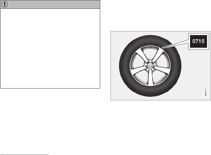
WHEELS AND TIRES
474
Tires
Your vehicle is equipped with tires according to
the vehicle's tire information placard on the B-
pillar (the structural member at the side of the
vehicle, at the rear of the driver's door opening).
CAUTION
Some Volvo models are equipped with an
Ultra High Performance tire and wheel com-
bination designed to provide maximum dry
pavement performance with consideration for
hydroplaning resistance. They may be more
susceptible to road hazard damage and,
depending on driving conditions, may achieve
a tread life of less than 20,000 miles (30,000
km). Even if this vehicle is equipped with Vol-
vo’s advanced AWD or stability system, these
tires are not designed for winter driving, and
should be replaced with winter tires when
weather conditions dictate.
The tires have good road holding characteristics
and offer good handling on dry and wet surfaces.
It should be noted however that the tires have
been developed to give these features on snow/
ice-free surfaces.
Most models are equipped with "all-season" tires,
which provide a somewhat higher degree of road
holding on slippery surfaces than tires without
the "all-season" rating. However, for optimum
road holding on icy or snow-covered roads, we
recommend suitable winter tires on all four
wheels.
When replacing tires, be sure that the new tires
are the same size designation, type (radial) and
preferably from the same manufacturer, on all
four wheels. Otherwise there is a risk of altering
the car's roadholding and handling characteris-
tics.
New tires
Remember that tires are perishable goods. As of
2000, the manufacturing week and year (Depart-
ment of Transportation (DOT) stamp) will be indi-
cated with 4 digits (e.g., 0715 means that the tire
illustrated was manufactured during week 7 of
2015).
Tire age
Tires degrade over time, even when they are not
being used. It is recommended that tires gener-
ally be replaced after 6 years of normal service.
Heat caused by hot climates, frequent high load-
ing conditions or Ultra Violet (U.V.) exposure can
accelerate the aging process. The temporary
spare1 should also be replaced at 6-year inter-
vals, even if it has never been used. A tire's age
can be determined by the DOT stamp on the
sidewall (see the illustration). A tire with e.g., visi-
ble cracks or discoloration should be replaced
immediately.
Tire economy
•Maintain correct tire pressure.
•Avoid fast starts, hard braking and tire
screeching.
•Tire wear increases with speed.
•Correct front wheel alignment is very impor-
tant.
•Unbalanced wheels impair tire economy and
driving comfort.
•Tires must maintain the same direction of
rotation throughout their lifetime.
•When replacing tires, the tires with the most
tread should be mounted on the rear wheels
1Not available in all models.
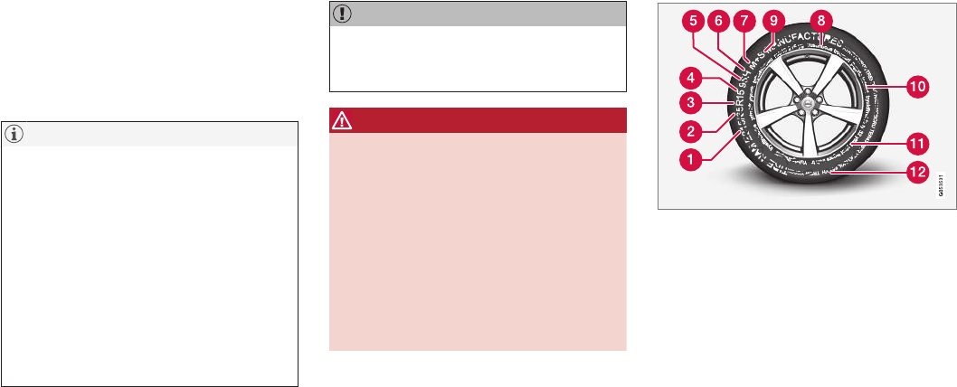
WHEELS AND TIRES
}}
475
to reduce the chance of oversteer during
hard braking.
•Hitting curbs or potholes can damage the
tires and/or wheels permanently.
Tire rotation
Your vehicle has no required tire rotation. Tire
wear is affected by a number of factors such as
tire inflation, ambient temperature, driving style,
etc.
NOTE
•If the tires are rotated, they should only
be moved from front to rear or vice versa.
They should never be rotated left to
right/right to left.
•Ideally, tire rotation should be done the
first time after approximately 3,000 miles
(5,000 km) and thereafter at 6,000-mile
(10,000-km) intervals. Some customers
find that tire rotation may help to get
extra mileage from tire life.
•Tire rotation should only be performed if
front/rear tire wear is fairly even and
tread height is above 1/16" (1.6 mm).
Storing wheels and tires
When storing complete wheels (tires mounted on
rims), they should be suspended off the floor or
placed on their sides on the floor.
Tires not mounted on rims should be stored on
their sides or standing upright, but should not be
suspended.
CAUTION
Tires should preferably be stored in a cool,
dry, dark place, and should never be stored in
close proximity to solvents, gasoline, oils, etc.
WARNING
•The wheel and tire sizes for your Volvo
are specified to meet stringent stability
and handling requirements. Unapproved
wheel/tire size combinations can nega-
tively affect your vehicle's stability and
handling.
•Any damage caused by installation of
unapproved wheel/tire size combinations
will not be covered by your new vehicle
warranty. Volvo assumes no responsibility
for death, injury, or expenses that may
result from such installations.
Related information
•Checking tire inflation pressure (p. 481)
•Tread wear indicator (p. 479)
Tire sidewall designations
The following information can be found on a
tire's sidewall.
Federal law mandates that tire manufacturers
place standardized information on the sidewall of
all tires (see the illustration).
The vehicle has been certified with certain combi-
nations of wheels and tires.
The following information is listed on the tire
sidewall:
The tire designation:
||
WHEELS AND TIRES
476
NOTE
Please be aware that the following tire desig-
nation is an example only and that this par-
ticular tire may not be available on your vehi-
cle.
1. 215: the width of the tire (in millimeters)
from sidewall edge to sidewall edge. The
larger the number, the wider the tire.
2. 65: The ratio of the tire's height to its width
in percent.
3. R: Radial tire (the designation RF and the
symbol indicate that the vehicle is
equipped with optional self-supporting run
flat tires2.
4. 15: The diameter of the wheel rim (in
inches).
5. 95: The tire's load index. In this example, a
load index of 95 equals a maximum load of
1521 lbs (690 kg).
6. H: The tire's speed rating, or the maximum
speed at which the tire is designed to be
driven for extended periods of time, carrying
a permissible load for the vehicle, and with
correct inflation pressure. For example, H
indicates a speed rating of 130 mph
(210 km/h).
NOTE
The tire's load index and speed rating may
not appear on the sidewall because they are
not required by law.
7. M+S or M/S = Mud and Snow, AT = All Ter-
rain, AS = All Season
8. U.S. DOT Tire Identification Number
(TIN): This begins with the letters "DOT" and
indicates that the tire meets all federal
standards. The next two numbers or letters
are the plant code where it was manufac-
tured, the next two are the tire size code and
the last four numbers represent the week
and year the tire was built. For example,
1510 means that the tire was manufactured
during week 15 of 2010. The numbers in
between are marketing codes used at the
manufacturer's discretion. This information
helps a tire manufacturer identify a tire for
safety recall purposes.
9. Tire Ply Composition and Material
Used: Indicates the number of plies indi-
cates or the number of layers of rubber-
coated fabric in the tire tread and sidewall.
Tire manufacturers also must indicate the ply
materials in the tire and the sidewall, which
include steel, nylon, polyester, and others.
10. Maximum Load: Indicates the maximum
load in pounds and kilograms that can be
carried by the tire. Refer to the vehicle's tire
information placard located on the B-Pillar
for the correct tire pressure for your vehicle.
11. Treadwear, Traction, and Temperature
grades.
12. Maximum permissible inflation
pressure: the greatest amount of air pres-
sure that should ever be put in the tire. This
limit is set by the tire manufacturer.
Speed Symbol
A tire's Speed Symbol (SS) indicates the maxi-
mum speed for which the tire has been certified
and should be at least equivalent to the vehicle's
top speed.
Winter tires, with our without studs, are excep-
tions and may use a lower SS. When winter tires
are installed, the vehicle may not be driven faster
than the tires' SS.
The vehicle's speed should always be determined
by the posted speed limit and traffic and road
conditions, not the tire's SS.
The following table indicates the maximum per-
missible speed for each SS.
2Self-supporting run flat tires may not be available on all models

WHEELS AND TIRES
}}
477
Speed Symbol
M 81 mph (130 km/h)
Q 100 mph (160 km/h)
T 118 mph (190 km/h)
H 130 mph (210 km/h)
V 149 mph (240 km/h)
W 168 mph (270 km/h)
Y 186 mph (300 km/h)
WARNING
•The wheel and tire sizes for your Volvo
are specified to meet stringent stability
and handling requirements. Unapproved
wheel/tire size combinations can nega-
tively affect your vehicle's stability and
handling.
•Any damage caused by installation of
unapproved wheel/tire size combinations
will not be covered by your new vehicle
warranty. Volvo assumes no responsibility
for death, injury, or expenses that may
result from such installations.
Wheel (rim) designations
Wheel and rim dimensions are shown in the fol-
lowing table.
The vehicle has been certified with certain combi-
nations of wheels and tires.
The following table shows an example of wheel
dimensions: 8Jx18x42.5. This wheel may not be
available on your vehicle.
8 Wheel width in inches
J Rim flange profile
18 Wheel diameter in inches
42.5 Offset in mm (distance from the center
of the wheel to the wheel's contact sur-
face on the hub)
Related information
•Tire sidewall designations (p. 475)
Tire terminology
The following is a glossary of tire-related terms.
The tire suppliers may have additional markings,
notes or warnings such as standard load, radial
tubeless, etc.
•Tire information placard: A placard show-
ing the OE (Original Equipment) tire sizes,
recommended inflation pressure, and the
maximum weight the vehicle can carry.
•Tire Identification Number (TIN): A number
on the sidewall of each tire providing infor-
mation about the tire brand and manufactur-
ing plant, tire size and date of manufacturer.
•Inflation pressure: A measure of the
amount of air in a tire.
•Standard load: A class of P-metric or Metric
tires designed to carry a maximum load at
35 psi [37 psi (2.5 bar) for Metric tires].
Increasing the inflation pressure beyond this
pressure will not increase the tires load car-
rying capability.
•Extra load: A class of P-metric or Metric
tires designed to carry a heavier maximum
load at 41 psi [43 psi (2.9 bar) for Metric
tires]. Increasing the inflation pressure
beyond this pressure will not increase the
tire's load carrying capability.
•kPa: Kilopascal, a metric unit of air pressure.
•PSI: Pounds per square inch, a standard unit
of air pressure.
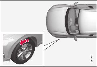
WHEELS AND TIRES
478
•B-pillar: The structural member at the side
of the vehicle behind the front door.
•Bead area of the tire: Area of the tire next
to the rim.
•Sidewall of the tire: Area between the bead
area and the tread.
•Tread area of the tire: Area of the perime-
ter of the tire that contacts the road when
mounted on the vehicle.
•Rim: The metal support (wheel) for a tire or a
tire and tube assembly upon which the tire
beads are seated.
•Maximum load rating: a figure indicating
the maximum load in pounds and kilograms
that can be carried by the tire. This rating is
established by the tire manufacturer.
•Maximum permissible inflation pressure:
the greatest amount of air pressure that
should ever be put in the tire. This limit is set
by the tire manufacturer.
•Recommended tire inflation pressure:
inflation pressure, established by Volvo,
which is based on the type of tires that are
mounted on a vehicle at the factory. This
information can be found on the tire inflation
placard(s) located on the driver's side B-pillar
and in the tire inflation table in this chapter.
•Cold tires: The tires are considered to be
cold when they have the same temperature
as the surrounding (ambient) air. This tem-
perature is normally reached after the vehicle
has been parked for at least 3 hours.
Tire direction of rotation
Incorrectly mounted tires impair the car's braking
properties and ability to force aside rain, snow
and slush.
The arrows shows the direction of rotation of the tire
•The tires with the most tread should always
be on the rear axle (to help reduce the risk of
skidding).
•When switching between summer and winter
tires, mark the tires to indicate where they
were mounted on the car, e.g., LF = left front,
RR = right rear
•Tires with tread designed to roll in only one
direction are marked with an arrow on the
sidewall.
•Contact a trained and qualified Volvo service
technician if you are unsure about the tread
depth.
Related information
•Tires (p. 474)
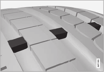
WHEELS AND TIRES
}}
479
Tread wear indicator
The tires have wear indicator strips running
across or parallel to the tread.
The letters TWI are printed on the side of the tire.
When approximately 1/16" (1.6 mm) is left on
the tread, these strips become visible and indi-
cate that the tire should be replaced. Tires with
less than 1/16" (1.6 mm) tread offer very poor
traction.
When replacing worn tires, it is recommended
that the tire be identical in type (radial) and size
as the one being replaced. Using a tire of the
same make (manufacturer) will help prevent
alteration of the driving characteristics of the
vehicle.
Related information
•Tire direction of rotation (p. 478)
•Checking tire inflation pressure (p. 481)
Loading specifications
Properly loading your vehicle will provide maxi-
mum return of vehicle design performance.
Weight designations
Before loading your vehicle, familiarize yourself
with the following terms for determining your
vehicle's weight ratings, with or without a trailer,
from the vehicle's Federal/Canadian Motor Vehi-
cle Safety Standards (FMVSS/CMVSS) label, and
the vehicle's tire information placard:
Curb weight
The weight of the vehicle including a full tank of
fuel and all standard equipment. It does not
include passengers, cargo, or optional equipment.
Capacity weight
All weight added to the curb weight, including
cargo and optional equipment. When towing,
trailer hitch tongue load is also part of cargo
weight.
Permissible axle weight
The maximum allowable weight that can be car-
ried by a single axle (front or rear). These num-
bers are shown on the Federal/Canadian Motor
Vehicle Safety Standards (FMVSS/CMVSS) label.
The total load on each axle must never exceed its
maximum permissible weight.
Gross vehicle weight (GVW)
The vehicle's curb weight + cargo + passengers.
Steps for Determining Correct Load
Limit
1. Locate the statement "the combined weight
of occupants and cargo should never exceed
XXX kg or XXX lbs." on your vehicle's plac-
ard.
2. Determine the combined weight of the driver
and passengers that will be riding in your
vehicle.
3. Subtract the combined weight of the driver
and passengers from XXX kg or XXX lbs.
4. The resulting figure equals the available
amount of cargo and luggage load capacity.
For example, if the "XXX" amount equals
1400 lbs. and there will be five 150 lb. pas-
sengers in your vehicle, the amount of availa-
ble cargo and luggage load capacity is
650 lbs. (1400 – 750 (5 × 150) = 650 lbs.)
5. Determine the combined weight of luggage
and cargo being loaded on the vehicle. That
weight may not safely exceed the available
cargo and luggage load capacity calculated
in Step 4.
6. If your vehicle will be towing a trailer, load
from your trailer will be transferred to your
vehicle. Consult this manual to determine
how this reduces the available cargo and lug-
gage load capacity of your vehicle.

||
WHEELS AND TIRES
480
WARNING
•Exceeding the permissible axle weight,
gross vehicle weight, or any other weight
rating limits can cause tire overheating
resulting in permanent deformation or
catastrophic failure.
•Do not use replacement tires with lower
load carrying capacities than the tires that
were original equipment on the vehicle
because this will lower the vehicle's GVW
rating. Use only tires with the correct load
carrying capacity. Consult your Volvo
retailer for information.
Related information
•Label information (p. 544)
•Weights (p. 549)
Uniform Tire Quality Grading
ALL PASSENGER VEHICLE TIRES MUST
CONFORM TO FEDERAL SAFETY REQUIRE-
MENTS IN ADDITION TO THESE GRADES.
Quality grades can be found, where applica-
ble, on the tire sidewall between the tread
shoulder and maximum section width. For
example:
Treadwear 200 Traction AA Temperature A
TREADWEAR
The treadwear grade is a comparative rating
based on the wear rate of the tire when tested
under controlled conditions on a specified gov-
ernment test course. For example, a tire graded
150 would wear one and one half (1 ½) times as
well on the government course as a tire graded
100. The relative performance of tires depends
upon the actual conditions of their use, however,
and many depart significantly from the norm due
to variation in driving habits, maintenance practi-
ces and differences in road characteristics and
climate.
TRACTION
The traction grades, from highest to lowest, are
AA, A, B, and C, as measured under controlled
conditions on specified government test surfaces
of asphalt and concrete. A tire marked C may
have poor traction performance. The traction
grade assigned to this tire is based on braking
(straight-ahead) traction tests and is not a meas-
ure of cornering (turning) traction.
WARNING
The traction grade assigned to this tire is
based on braking (straight-ahead) traction
tests and is not a measure of cornering (turn-
ing) traction.
TEMPERATURE
The temperature grades are A (the highest), B,
and C, representing the tire's resistance to the
generation of heat and its ability to dissipate heat
when tested under controlled conditions on a
specified indoor laboratory test wheel. Sustained
high temperature can cause the material of the
tire to degenerate and reduce tire life, and exces-
sive temperature can lead to sudden tire failure.
The grade C corresponds to a minimum level of
performance that all passenger vehicle tires must
meet under the Federal Motor Safety Standard
No. 109. Grades B and A represent higher levels
of performance on the laboratory test wheel than
the minimum required by law.
WARNING
The temperature grade for this tire is estab-
lished for a tire that is properly inflated and
not overloaded. Excessive speed, under-infla-
tion, or excessive loading, either separately or
in combination, can cause heat buildup and
tire failure.
WHEELS AND TIRES
}}
481
Snow tires and chains
The use of snow chains and/or winter tires can
help improve traction in winter driving conditions.
Snow chains can be used on your Volvo with the
following restrictions:
•Snow chains should be installed on front
wheels only. Use only Volvo approved snow
chains.
•If accessory, aftermarket or "custom" tires
and wheels are installed and are of a size dif-
ferent than the original tires and wheels,
chains in some cases CANNOT be used.
Sufficient clearances between chains and
brakes, suspension and body components
must be maintained.
•Some strap-on type chains will interfere with
brake components and therefore CANNOT
be used.
•All Wheel Drive models: Snow chains
should only be installed on the front wheels.
•Certain size tires may not allow the assembly
of snow chains/traction devices.
Consult your Volvo retailer for additional snow
chain information.
CAUTION
•Snow chains should not be used on
wheels larger than 19".
•Always follow the chain manufacturer's
installation instructions carefully. Install
chains as tightly as possible and
retighten periodically.
•Check local regulations regarding the use
of snow chains before installing.
•Use single-sided snow chains only.
•Never exceed the chain manufacturer's
specified maximum speed limit. (Under
no circumstances should you exceed
31 mph (50 km/h).
•Avoid bumps, holes or sharp turns when
driving with snow chains.
•The handling of the vehicle can be
adversely affected when driving with
chains. Avoid fast or sharp turns as well
as locked wheel braking.
Checking tire inflation pressure
Correct tire inflation pressure helps improve driv-
ing stability, save fuel and increase the service
life of the tires.
WARNING
•Under-inflation is the most common
cause of tire failure and may result in
severe tire cracking, tread separation, or
"blow-out," with unexpected loss of vehi-
cle control and increased risk of injury.
•Under-inflated tires reduce the load car-
rying capacity of your vehicle.
Cold tires
Inflation pressure should be checked when the
tires are cold.
The tires are considered to be cold when
they have the same temperature as the sur-
rounding (ambient) air.
This temperature is normally reached after the
vehicle has been parked for at least 3 hours.
After driving a distance of approximately 1 mile
(1.6 km), the tires are considered to be hot. If you
have to drive farther than this distance to pump
your tire(s), check and record the tire pressure
first and add the appropriate air pressure when
you get to the pump.
When weather temperature changes occur, tire
inflation pressures also change. A 10-degree
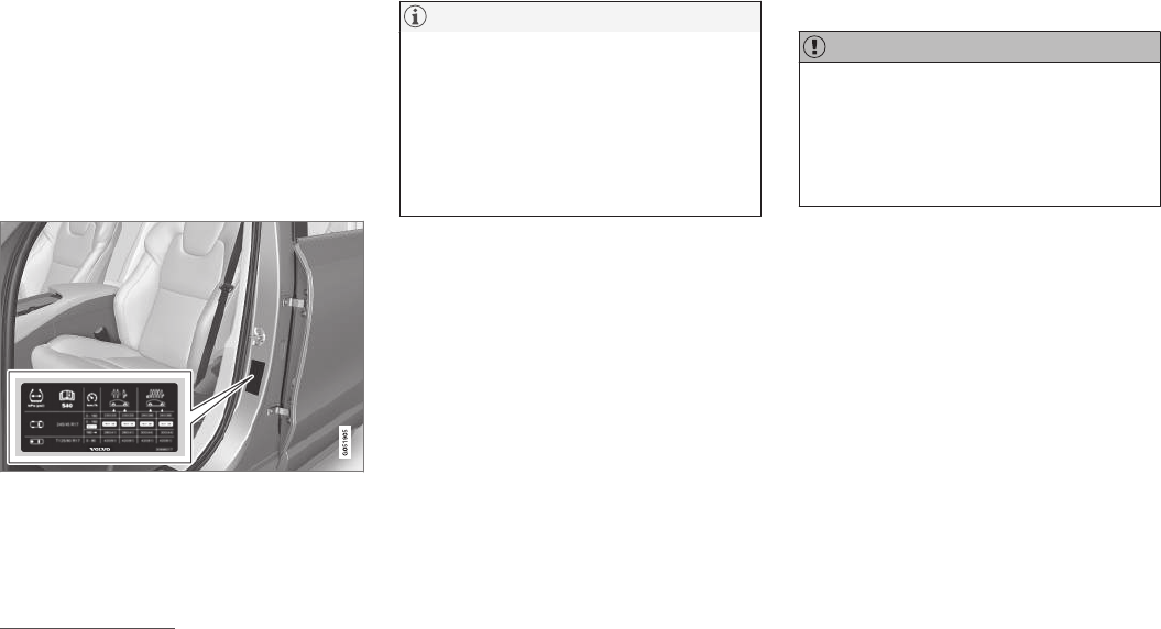
||
WHEELS AND TIRES
482
temperature drop causes a corresponding drop
of 1 psi (7 kPa) in inflation pressure. Check your
tire pressures frequently and adjust them to the
proper pressure, which can be found on the vehi-
cle's tire information placard or certification label.
If checking tire pressure when the tire is hot,
never "bleed" or reduce air pressure. The tires
are hot from driving and it is normal for pressures
to increase above recommended cold pressures.
A hot tire at or below recommended cold inflation
pressure could be significantly under-inflated.
Recommended inflation pressures
Tire inflation placard
A tire inflation pressure placard is located on the
driver's side B-pillar (the structural member at the
side of the vehicle, at the rear of the driver's door
opening). This placard indicates the designation
of the factory-mounted tires on your vehicle, as
well as load limits and inflation pressure.
NOTE
•The placard shown indicates inflation
pressure for the tires installed on the
vehicle at the factory only.
•A certain amount of air seepage from the
tires occurs naturally and tire pressure
fluctuates with seasonal changes in tem-
perature. Always check tire pressure reg-
ularly.
•Use a tire gauge to check the tire inflation
pressure, including the spare3, at least once
a month and before long trips. You are
strongly urged to buy a reliable tire pressure
gauge, as automatic service station gauges
may be inaccurate.
•Use the recommended cold inflation pres-
sure for optimum tire performance and wear.
•Under-inflation or over-inflation may cause
uneven treadwear patterns.
Checking tire pressure
1. Remove the cap from the valve on one tire,
then firmly press the tire gauge onto the
valve.
2. Add air to reach the recommended air pres-
sure.
3. Replace the valve cap.
CAUTION
•After inflating the tires, always reinstall the
valve cap to help avoid damage to the
valve from dirt, gravel, etc.
•Use plastic valve caps only. Metal caps
could corrode and become difficult to
remove.
4. Visually inspect the tires to make sure there
are no nails or other objects embedded that
could puncture the tire and cause an air leak.
5. Check the sidewalls to make sure there are
no gouges, cuts, bulges or other irregulari-
ties.
6. Repeat this procedure for each tire, including
the spare.
3Not available in all models.
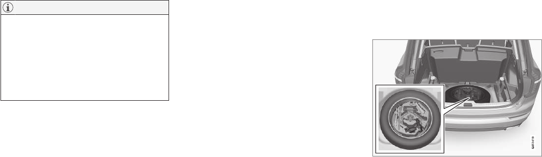
WHEELS AND TIRES
* Option/accessory, for more information, see Introduction. 483
NOTE
•If you overfill the tire, release air by push-
ing on the metal stem in the center of the
valve. Then recheck the pressure with
your tire gauge.
•Some spare tires require higher inflation
pressure than the other tires. Consult the
tire inflation pressure table or the inflation
pressure placard.
Changing tires
When changing wheels to another dimension,
always follow Volvo's instructions.
When changing to tires of another
dimension
If you mount tires with a dimension other than
the factory-installed tires, contact an authorized
Volvo retailer to update the vehicle's software.
This may also be necessary when changing from
summer to winter tires, or vice versa.
Related information
•Snow tires and chains (p. 481)
•Spare tire (p. 484)
•Installing a wheel (p. 487)
•Removing a wheel (p. 486)
Tools in the cargo compartment
Tools for e.g., changing wheels, etc. are located
under the cargo compartment floor.
The foam block under the cargo compartment
floor contains the towing eyelet, the tool for
removing plastic wheel bolt covers, the jack* and
the lug wrench*. There is also a storage space for
the tool used to remove locking wheel bolts.
WHEELS AND TIRES
* Option/accessory, for more information, see Introduction.
484
Jack
The jack is used to raise the vehicle, for example
when mounting winter wheels, etc.
WARNING
•The jack must correctly engage the jack
attachment.
•Be sure the jack is on a firm, level, non-
slippery surface.
•Never allow any part of your body to be
extended under a vehicle supported by a
jack.
•Use the jack intended for the vehicle
when changing a tire. For any other job,
use stands to support the vehicle.
•Apply the parking brake and put the gear
selector in the Park (P) position.
•Block the wheels standing on the ground,
use rigid wooden blocks or large stones.
•The jack should be kept well-greased and
clean, and should not be damaged.
•No objects should be placed between the
base of jack and the ground, or between
the jack and the attachment bar on the
vehicle.
CAUTION
•When not in use, the jack* should be kept
in its storage compartment under the
cargo compartment floor.
•The jack provided with your vehicle is
intended to be used only in temporary sit-
uations such as changing wheels in the
event of a flat tire. Only the jack that
came with your particular model should
be used to lift the vehicle. If the vehicle
needs to be lifted more frequently or for a
prolonged period, using a garage jack or
hoist is recommended. Always follow this
device’s instructions for use.
Models with leveling control*
If the vehicle is equipped with the optional pneu-
matic suspension, this feature must be turned off
before raising the vehicle with the jack.
To do so, go to Settings Vehicle
Deactivate Suspension & Leveling Control in
the center display's Top view.
Spare tire
The spare tire in your vehicle is called a
"Temporary Spare".
NOTE
•The vehicle should never be driven
faster than 50 mph (80 km/h) when
the spare tire is being used.
•The spare tire is only intended for tempo-
rary use. Replace it with a normal wheel
as soon as possible.
•The vehicle's handling may be altered by
the use of the spare tire and ground
clearance will be reduced. Do not wash
the vehicle in an automatic car wash if
the Temporary Spare is being used.
•Recommended tire pressure (see the
placard on the B-pillar) should be main-
tained irrespective of which position on
the vehicle the temporary spare tire is
used on.
•In the event of damage to this tire, a new
one can be purchased from your Volvo
retailer.
WHEELS AND TIRES
* Option/accessory, for more information, see Introduction. 485
WARNING
Current legislation prohibits the use of the
"Temporary Spare" tire other than as a tem-
porary replacement for a punctured tire. It
must be replaced as soon as possible by a
standard tire. Road holding and handling may
be affected with the "Temporary Spare" in
use. Do not exceed 50 mph (80 km/h).
CAUTION
The vehicle must not be driven with wheels of
different dimensions or with a spare tire other
than the one that came with the vehicle. The
use of different size wheels can seriously
damage your car's transmission.
CAUTION
The vehicle must never be driven with more
than one temporary spare wheel.
The spare tire is located under the floor of the
cargo compartment. A retaining bolt holds the
spare tire and foam block containing tools in
place.
Accessing the spare tire
1. Lift the rear edge of the cargo compartment
floor.
2. Unscrew the retaining bolt.
3. Lift out the foam block holding the tools.
4. Lift out the spare tire.
Related information
•Changing tires (p. 483)
•Removing a wheel (p. 486)
•Wheel bolts (p. 485)
•Checking tire inflation pressure (p. 481)
Wheel bolts
The wheel bolts hold the wheel in place.
CAUTION
Wheel bolts should be tightened to 103 ft.
lbs. (140 Nm). Over-tightening could damage
the threads.
Only use wheels/rims that have been tested and
approved by Volvo and are included in Volvo's
product range. Use a torque wrench to check
that the wheel bolts are tightened correctly.
Locking wheel bolts*
A tool for removing locking wheel bolts can be
found in the foam block under the cargo com-
partment floor.
Related information
•Changing tires (p. 483)
•Installing a wheel (p. 487)
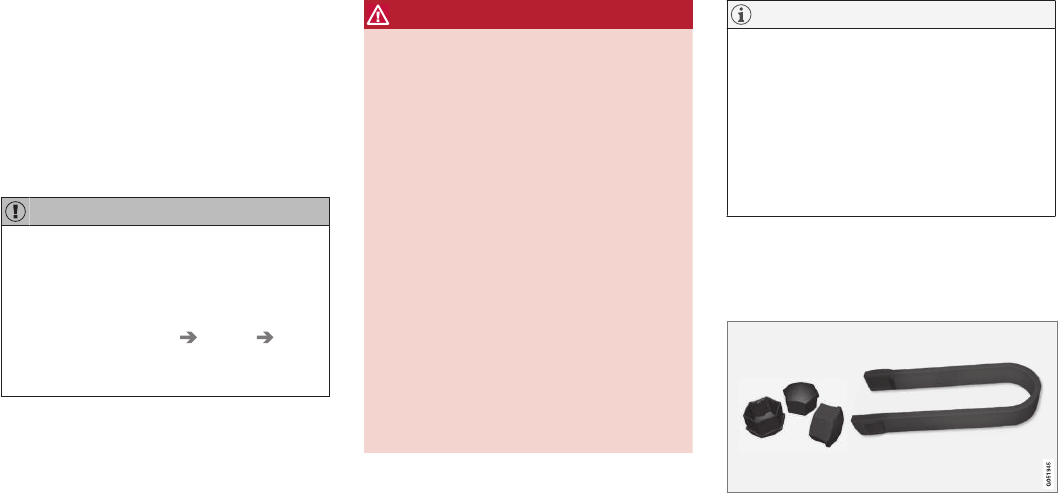
WHEELS AND TIRES
* Option/accessory, for more information, see Introduction.
486
Removing a wheel
Wheel changes should always be carried out
correctly.
1. Turn on the hazard warning flashers if the
wheel change has to be done near passing
traffic.
2. Apply the parking brake and put the gear
selector in P.
CAUTION
Models with suspension and level con-
trol*:
Turn this function off before raising the vehi-
cle.
To do so, go to Settings Vehicle
Deactivate Suspension & Leveling Control
in the center display's Top view.
WARNING
•The jack must correctly engage the jack
attachment.
•Be sure the jack is on a firm, level, non-
slippery surface.
•Never allow any part of your body to be
extended under a vehicle supported by a
jack.
•Use the jack intended for the vehicle when
changing a tire. For any other job, use
stands to support the vehicle.
•Apply the parking brake and put the gear
selector in the Park (P) position.
•Block the wheels standing on the ground,
use rigid wooden blocks or large stones.
•The jack should be kept well-greased and
clean, and should not be damaged.
•No objects should be placed between the
base of jack and the ground, or between
the jack and the attachment bar on the
vehicle.
NOTE
The jack provided with your vehicle is
intended to be used only in temporary situa-
tions such as changing wheels in the event of
a flat tire. Only the jack that came with your
particular model should be used to lift the
vehicle. If the vehicle needs to be lifted more
frequently or for a prolonged period, using a
garage jack or hoist is recommended. Always
follow this device’s instructions for use.
3. Take out the jack*, lug wrench*, the tool for
removing the plastic covers on the wheel
bolts and the towing eyelet stowed under the
floor of the cargo compartment.
Tool for removing the plastic covers on the wheel bolts
Remove the plastic covers on the wheel bolts.
4. Block the wheels that are on the ground with
wooden blocks or large stones.

WHEELS AND TIRES
}}
487
5.
Lug wrench and towing eyelet
Screw the towing eyelet into the lug wrench
as shown in the illustration.
CAUTION
The towing eyelet must be screwed into the
lug wrench as far as possible.
6. With the vehicle still on the ground, use the
lug wrench/towing eyelet to loosen the
wheel bolts ½ – 1 turn by exerting downward
(counterclockwise) pressure.
7. When hoisting the vehicle, it is essential that
the jack (or garage lift arms) are positioned
correctly on the underside of the vehicle.
There are two jack attachment points on
each side of the vehicle and there is a groove
in the plastic cover at each attachment point.
Position the jack under the attachment point
to be used on a level, firm, non-slippery sur-
face and crank it up until it is correctly
aligned and seated in the attachment point.
The pin on the jack's head must be posi-
tioned in the hole in the attachment point.
8. Raise the vehicle until the wheel to be
changed is lifted off the ground. Remove the
wheel bolts.
Related information
•Wheel bolts (p. 485)
•Installing a wheel (p. 487)
•Jack (p. 484)
Installing a wheel
It is important to install wheels properly.
1. Clean the contact surfaces on the wheel and
hub.
2. Lift the wheel and place it on the hub.
3. Install the wheel bolts and tighten hand-tight.
Using the lug wrench, tighten crosswise until
all bolts are snug.
4. Lower the vehicle to the ground and alter-
nately tighten the bolts crosswise to
103 ft. lbs. (140 Nm).
5. Press the plastic covers onto the wheel bolts.
||
WHEELS AND TIRES
488
CAUTION
•After inflating the tires, always reinstall
the valve cap to help avoid damage to the
valve from dirt, gravel, etc.
•Use plastic valve caps only. Metal caps
could corrode and become difficult to
remove.
Related information
•Wheel bolts (p. 485)
•Jack (p. 484)
Tire Pressure Monitoring System
(TPMS)
TPMS provides a warning if inflation pressure in
one or more tires is too low. It also uses a sym-
bol (called a telltale) that will flash for
60 seconds and then glow steadily if there is a
system malfunction.
TPMS uses sensors mounted in the tire valves to
check inflation pressure levels. When the vehicle
is moving at a speed of approximately 20 mph
(30 km/h) or faster, these sensors transmit infla-
tion pressure data to a receiver located in the
vehicle. If inflation pressure is too low, an indica-
tor symbol will illuminate in the instrument panel
and a text message will be displayed.
Symbol Explanation
The symbol illuminates to indicate
low tire inflation pressure.
If a malfunction occurs in the sys-
tem, the tire pressure warning sym-
bol will flash for approximately
1 minute and then remain illumi-
nated.
Each tire, including the spare (if provided), should
be checked monthly when cold and inflated to
the inflation pressure recommended by the vehi-
cle manufacturer on the vehicle placard or tire
inflation pressure label. (If your vehicle has tires
of a different size than the size indicated on the
vehicle placard or tire inflation pressure label, you
should determine the proper tire inflation pres-
sure for those tires.)
As an added safety feature, your vehicle has
been equipped with a tire pressure monitoring
system (TPMS) that illuminates a low tire pres-
sure telltale when one or more of your tires is
significantly under-inflated. Accordingly, when the
low tire pressure telltale illuminates, you should
stop and check your tires as soon as possible,
and inflate them to the proper pressure.
Driving on a significantly under-inflated tire cau-
ses the tire to overheat and can lead to tire fail-
ure. Under-inflation also reduces fuel efficiency
and tire tread life, and may affect the vehicle's
handling and stopping ability. Please note that
the TPMS is not a substitute for proper tire main-
tenance, and it is the driver's responsibility to
maintain correct tire pressure, even if under-infla-
tion has not reached the level to trigger illumina-
tion of the TPMS low tire pressure telltale.
Your vehicle has also been equipped with a
TPMS malfunction indicator to indicate when the
system is not operating properly. The TPMS mal-
function indicator is combined with the low tire
pressure telltale.
When the system detects a malfunction, the tell-
tale will flash for approximately one minute and
then remain continuously illuminated. This
sequence will continue upon subsequent vehicle

WHEELS AND TIRES
}}
489
start-ups as long as the malfunction exists. When
the malfunction indicator is illuminated, the sys-
tem may not be able to detect or signal low tire
pressure as intended.
TPMS malfunctions may occur for a variety of
reasons, including the installation of replacement
or alternate tires or wheels on the vehicle that
prevent the TPMS from functioning properly.
Always check the TPMS malfunction telltale after
replacing one or more tires or wheels on your
vehicle to ensure that the replacement or alter-
nate tires and wheels allow the TPMS to con-
tinue to function properly.
Messages in the instrument panel
When the TPMS symbol illuminates, the following
text messages may also be displayed:
•Tire pressure low: the tire(s) affected will
also be specified.
•Tire needs air now: the tire(s) affected will
also be specified.
•Tire pressure system Service required.
If TPMS cannot determine which tire(s) have low
inflation pressure, general messages may be dis-
played, such as:
•Tire pressure low Check tires
•Tire needs air now Check tires
TPMS sensors can be installed on the valve hole
area, on the factory-installed wheels as well as on
optional ones.
If a spare wheel or other wheel without a TPMS
sensor is used, a fault message will appear in the
instrument panel after driving for a few minutes.
After changing wheels, always check that the
new wheels have TPMS sensors to avoid a sys-
tem malfunction warning.
TPMS does not replace the need for regular tire
inspection and maintenance.
Recommendations
TPMS sensors should be mounted on all wheels
used with the vehicle, including winter wheels.
NOTE
•If you change to tires with a different
dimension than the factory-installed ones,
the TPMS system must be reconfigured
for these tires. This must be done by a
trained and qualified Volvo service techni-
cian.
•If a tire is changed, or if the TPMS sensor
is moved to another wheel, the rubber
valve and valve core should be replaced.
•When installing TPMS sensors, the vehi-
cle must be parked for at least
15 minutes with the ignition off. If the
vehicle is driven within 15 minutes, a
TPMS error message will be displayed.
WARNING
Incorrect inflation pressure could lead to tire
failure, resulting in a loss of control of the
vehicle.
Turning TPMS off4
TPMS can be turned off in the center display's
Top view.
1. Park the vehicle and turn off the engine.
2. Activate ignition mode I.
4Certain markets only.
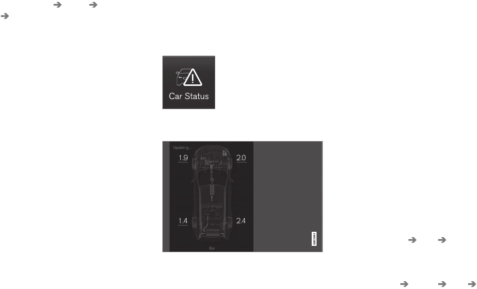
||
WHEELS AND TIRES
490
3. Select Settings My Car IntelliSafe
Tire Pressure Monitor in the Top view
and deselect (tap) the button.
> The function will remain off until it is reac-
tivated.
Related information
•Checking inflation pressure (p. 490)
•Reinflating tires equipped with the Tire
Pressure Monitoring System (TPMS)
(p. 491)
•Tire Pressure Monitoring System type appro-
val (p. 492)
•Ignition modes (p. 360)
Checking inflation pressure
The Tire Pressure Monitoring System makes it
possible to view the current inflation pressure of
all four tires.
Checking inflation pressure
Open the Car status app in
the center display's Application
view. Tap Status to see the
current inflation pressure of all
four tires.
The on-screen graphic displays the inflation pres-
sure.
The illustration is generic and may vary from model to
model or after a software update
Color indications:
•No color indicator: tire pressure is above
the threshold for a low inflation pressure
warning.
•Yellow: low tire pressure. Stop and check/
reinflate the tire(s) as soon as possible.
•Red: inflation pressure is very low. Stop
immediately and check/reinflate the tire(s).
•When no tire pressure values or updated tire
pressure values are shown then system has
not learned the tire pressure values. It might
be necessary to drive at a speed of at least
20 mph (30 km/h) for several minutes.
•If the TPMS symbol (telltale) flashes for
approx. 1 minute then glows steadily, and the
message Tire pressure system Service
required is displayed: this indicates that the
system is not functioning correctly. Have it
checked by a trained and qualified Volvo
service technician.
Please note that the sample tire pressures
shown in the illustration are in bar. The unit of
measure can be changed (e.g., to pound per
scare inch (psi) in the center display's Settings
menu, under System Units Tire Pressure.
Tire Pressure Monitoring System settings
The unit of measure for tire inflation pressure can
be changed in the center display's Top view by
selecting Settings System Units Tire
Pressure and tapping the desired unit.
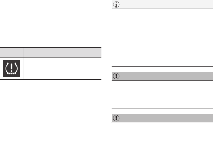
WHEELS AND TIRES
}}
491
Related information
•Calibrating the Tire Pressure Monitoring
System (TPMS) (p. 492)
•Reinflating tires equipped with the Tire
Pressure Monitoring System (TPMS)
(p. 491)
•Tire Pressure Monitoring System (TPMS)
(p. 488)
Reinflating tires equipped with the
Tire Pressure Monitoring System
(TPMS)
When low tire pressure has been detected, a
message will be displayed in the instrument
panel and the Tire Pressure Monitoring System
symbol will illuminate.
Symbol Explanation
Check and reinflate the tire(s)
when the TPMS symbol illuminates
and a message is displayed.
1. Use a tire pressure gauge to check the infla-
tion pressure of the under-inflated tire(s).
2. Re-inflate the tire(s) to the correct pressure
(consult the tire pressure placard located on
the driver's side B-pillar (the structural mem-
ber at the side of the vehicle, at the rear of
the driver's door opening).
3. In some cases, it may be necessary to drive
the vehicle for several minutes at a speed of
at least 20 mph (30 km/h) to erase the
TPMS telltale warning and the text message.
Please be aware that the TPMS telltale
warning will not go out until the low tire pres-
sure has been corrected.
NOTE
To help avoid incorrect tire inflation pressure,
if possible only inflate the tires when they are
cold. The tires are considered to be cold
when they have the same temperature as the
surrounding (ambient) air. This temperature is
normally reached after the vehicle has been
parked for at least 3 hours. After driving a dis-
tance of approximately 1 mile (1.6 km), the
tires are considered to be warm.
CAUTION
When inflating tires with TPMS sensors, press
the pump's mouthpiece straight onto the
valve to help avoid bending or otherwise dam-
aging the valve.
CAUTION
•After inflating the tires, always reinstall
the valve cap to help avoid damage to the
valve from dirt, gravel, etc.
•Use plastic valve caps only. Metal caps
could corrode and become difficult to
remove.

||
WHEELS AND TIRES
492
WARNING
•Incorrect inflation pressure could lead to
tire failure, resulting in a loss of control of
the vehicle.
•Tire monitoring systems cannot indicate
sudden tire damage caused by external
factors (e.g., a blowout) in advance.
Related information
•Tire Pressure Monitoring System (TPMS)
(p. 488)
•Checking inflation pressure (p. 490)
Calibrating the Tire Pressure
Monitoring System (TPMS)6
In certain situations, a text pertaining to calibra-
tion requirements may appear in the center dis-
play. This text is generic and does not apply
to North American models.
Tire Pressure Monitoring System
type approval
NOTE
USA
FCC ID: MRXVHSS4
Canada
IC:2546A-VHSS4
M :VHSS4
This device complies with part 15 of the FCC
rules and with licence exempt RSS standards
of Industry Canada.
Operation is subject to the following condi-
tions:
(1) This device may not cause harmful inter-
ference, and
(2) this device must accept any interference
received, including interference that may
cause undesired operation.
6Certain markets only.
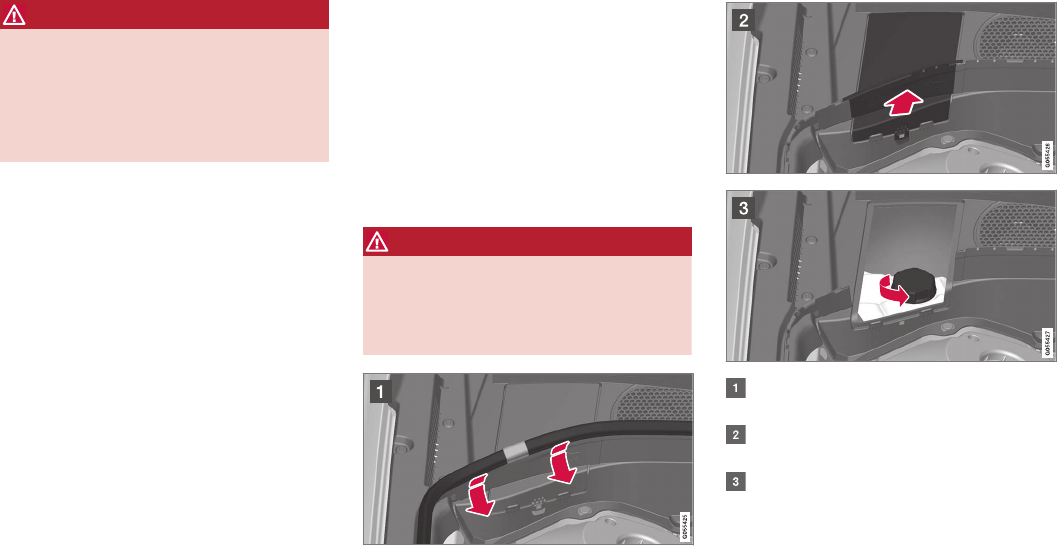
WHEELS AND TIRES
}}
493
WARNING
Changes or modifications not expressively
approved by the party responsible for compli-
ance could void the user's authority to oper-
ate the equipment. The term “IC:” before the
radio certification number only signifies that
Industry Canada technical specifications were
met.
Refilling coolant
Coolant helps keep the gasoline engine at the
proper operating temperature. The heat transfer-
red from the engine to the coolant can be used
to warm the passenger compartment.
When refilling coolant, follow the instructions on
the package and use the recommended amount
of coolant. Never fill the cooling system with
water only; this could lead to freezing, corrosion
and engine damage.
WARNING
If the engine has been running, the coolant
will be very hot. Allow the engine to cool
before opening the coolant expansion tank. If
this is not possible, open the cap very slowly
to allow pressure to dissipate.
Lift the rubber strip by pressing it inward in
the engine compartment.
Remove the plastic cover by folding out the
catch and lifting the cover upward.
Remove the expansion tank and add coolant.
The level should be between the MIN and
MAX marks on the tank.
Put the other components back in place in the
reverse order.

||
WHEELS AND TIRES
494
CAUTION
•High levels of chlorine, chlorides and
other salts may cause corrosion in the
cooling system.
•Only use coolants with corrosion protec-
tion recommended by Volvo.
•The ratio of coolant to water is 50/50.
•Mix the coolant with tap water of drinka-
ble quality.
•If maintenance is performed on the cool-
ing system or if the coolant is replaced,
flush the cooling system with clean water
before adding new a new coolant/water
mixture.
•The engine may only be operated with a
properly filled cooling system. Otherwise,
high temperatures and cracks in the cyl-
inders may occur.
Related information
•Coolant specifications and volumes (p. 553)

MAINTENANCE AND SERVICING

MAINTENANCE AND SERVICING
496
Volvo's service program
Periodic maintenance and service performed at
the intervals specified in your Warranty and
Service Records Information booklet will help
keep your vehicle running well.
Introduction
The maintenance services contain several checks
that require special instruments and tools and
therefore must be performed by a qualified tech-
nician. To keep your Volvo in top condition, spec-
ify time-tested and proven Genuine Volvo Parts
and Accessories.
The Federal Clean Air Act – U.S.
The Federal Clean Air Act requires vehicle manu-
facturers to furnish written instructions to the ulti-
mate purchaser to assure the proper servicing
and function of the components that control
emissions. These services, which are listed in the
"Warranty and Service Records Information"
booklet, are not covered by the warranty. You will
be required to pay for labor and material used.
Maintenance
Your Volvo passed several major inspections
before it was delivered to you, in accordance with
Volvo specifications. The maintenance proce-
dures outlined in the Warranty and Service
Records Information booklet, many of which will
positively affect your vehicle's emissions, should
be performed as indicated. It is recommended
that receipts for vehicle emission maintenance be
retained in case questions arise concerning
maintenance. Inspection and maintenance should
also be performed anytime a malfunction is
observed or suspected.
Applicable warranties – U.S./Canada
In accordance with applicable U.S. and Canadian
regulations, the following list of warranties is pro-
vided.
•New Vehicle Limited Warranty
•Parts and Accessories Limited Warranty
•Corrosion Protection Limited Warranty
•Seat Belt and Supplemental Restraint Sys-
tems Limited Warranty
•Emission Design and Defect Warranty
•Emission Performance Warranty
These are the federal warranties; other warran-
ties are provided as required by state/provincial
law. Refer to your separate Warranty and Service
Records Information booklet for detailed informa-
tion concerning each of the warranties.
Periodic maintenance helps minimize
emissions
NOTE
•Refer to your Warranty and Service
Records Information booklet for a com-
prehensive service and maintenance
schedule up to 150,000 miles (240,000
km). This program contains inspections
and services necessary for the proper
function of your vehicle and includes
components that affect vehicle emis-
sions.
•The Warranty and Service Records Infor-
mation booklet also contains detailed
information concerning the warranties
that apply to your vehicle.
On-board Diagnostic System
OBD II is part of your vehicle's computerized
engine management system. It stores diagnostic
information about your vehicle's emission con-
trols. It can light the Check Engine light (MIL) if it
detects an emission control "fault." A "fault" is a
component or system that is not performing
within an expected range. A fault may be perma-
nent or temporary. OBD II will store a message
about any fault.

MAINTENANCE AND SERVICING
497
Emission inspection readiness
How do states use OBD II for emission
inspections?
Many states connect a computer directly to a
vehicle's OBD II system. The inspector can then
read "faults." In some states, this type of inspec-
tion has replaced the tailpipe emission test.
How can my vehicle fail OBD II emission
inspection?
Your vehicle can fail OBD II emission inspection
for any of the following reasons.
•If your Check Engine (MIL) light is lit, your
vehicle may fail inspection.
•If your vehicle's Check Engine light was lit,
but went out without any action on your part,
OBD II will still have a recorded fault. Your
vehicle may pass or fail, depending on the
inspection practices in your area.
•If you had recent service that required dis-
connecting the battery, OBD II diagnostic
information may be incomplete and "not
ready" for inspection. A vehicle that is not
ready may fail inspection.
How can I prepare for my next OBD II
emission inspection?
•If your Check Engine (MIL) light is lit – or was
lit but went out without service, have your
vehicle diagnosed and, if necessary, serviced
by a qualified Volvo technician.
•If you recently had service for a lit Check
Engine light, or if you had service that
required disconnecting the battery, a period
of driving is necessary to bring the OBD II
system to "ready" for inspection. Two half-
hour trips of mixed stop-and-go/highway
driving are typically needed to allow OBD II to
reach readiness. Your Volvo retailer can pro-
vide you with more information on planning a
trip.
•Maintain your vehicle in accordance with your
vehicle's maintenance schedule.
Owner maintenance
Periodic maintenance requirements and intervals
are described in your vehicle's Warranty and
Service Records Information booklet.
The following points can be carried out between
the normally scheduled maintenance services.
Each time the car is refueled:
•Check the engine oil level.
•Clean the windshield, windshield wipers,
headlights, and taillights.
Monthly:
•Check cold tire pressure in all tires. Inspect
the tires for wear.
•Check that engine coolant and other fluid
levels are between the indicated "min" and
"max" markings.
•Clean interior glass surfaces with a glass
cleaner and soft paper towels.
•Wipe driver information displays with a soft
cloth.
•Visually inspect battery terminals for corro-
sion. Corrosion may indicate a loose terminal
connector, or a battery near the end of its
useful service life. Consult your Volvo retailer
for additional information.
As needed:
Wash the car, including the undercarriage, to
reduce wear that can be caused by a buildup of
dirt, and corrosion that can be caused by salt res-
idues.
Clean leaves and twigs from air intake vents at
the base of the windshield, and from other places
where they may collect.
NOTE
Complete service information for qualified
technicians is available online for purchase or
subscription at www.volvotechinfo.com.
Related information
•Climate system service (p. 503)
MAINTENANCE AND SERVICING
498
System updates
Updates are available for infotainment-related
services and Internet connections. If system soft-
ware updates are available, they can be to be
downloaded all at once or separately.
System (software) updates are
handled through the Remote
update service app in the
center display's App view. Tap
once to start a download app in
Home view's lower sub-view. If
no search for updates has
been performed since the last time the infotain-
ment system was started, a search will be initi-
ated.
No search will begin if a software download is
underway.
An icon in the System updates button indicates
the number of updates that are currently availa-
ble. Tap the button to display a list of updates
that can be installed in the vehicle.
For additional information and answers to com-
monly asked questions pertaining to the function
and downloading system updates, go to sup-
port.volvocars.com.
Background searches for software updates
is activated by default when the vehicle is
delivered from the factory.
NOTE
Downloading data may affect other system
features that share the Internet connection. A
download can be cancelled at any time or the
other features can be temporarily turned off
while the software download is underway.
NOTE
An update may be interrupted when the igni-
tion is switched off.
However, an update does not have to be
completed when the ignition is switched off; it
will resume automatically when the ignition is
switched on again.
Updating all system software
–Select Install all at the bottom of the list.
To avoid displaying a list, select Install all by the
System updates button.
Updating individual programs
–Select Install to choose the software to be
downloaded.
Cancelling a download
–Tap the activity indicator that replaced the
Install button on the screen when the down-
load began.
Keep in mind that a download can be cancelled
but an installation that has already begun cannot
be interrupted.
Allowing background searches or
software updates
This function can be deactivated from the center
display:
1. Go to the Settings in the center display's Top
view and select Remote Update Service.
2. Tap System Remote Update Service.
3. Tap to deselect Auto Software Update.
If an update is available, New software updates
available will appear in the center display's sta-
tus bar. Tap the message to start a download app
in Home view's lower sub-view. As soon as the
download app has started, an icon in the System
updates button will indicate the number of
downloads available.
Related information
•Center display overview (p. 28)
•Navigating in the center display's views
(p. 38)
MAINTENANCE AND SERVICING
}}
499
Remote updates
With the vehicle connected to the Internet,
updates for a number of the vehicle's systems
can be downloaded from the center display.
The Remote updates app is
started from the center dis-
play's App view and makes it
possible to:
•search for and update system software
•update the Sensus Navigation maps
•download, update and uninstall apps
Related information
•Downloading, updating and uninstalling apps
(p. 413)
•System updates (p. 498)
•Map updates with MapCare (p. 465)
Vehicle status
The vehicle's general status can be displayed in
the center display along with the possibility to
book service1
The Car status app is started
in the center display's App view
and has three tabs:
•Messages: stored messages
•Status: tire pressure and engine oil level
•Appointments: booking service or repairs1
Related information
•Using the center display (p. 45)
•Booking service and repairs (p. 499)
•Checking inflation pressure (p. 490)
•Checking and refilling engine oil (p. 531)
Booking service and repairs
Connected Service Booking (CSB) makes it
possible to use the vehicle's Internet connection
to set up a time for service, maintenance and/or
repairs.
The information is handled through the Car
status app, which can be opened from the cen-
ter display's App view.
Information about your vehicle is sent to your
retailer and you can book your workshop appoint-
ment directly in your retailer's workshop planning
system using the Volvo On-Line Service Schedu-
ler with your smart phone. The system will also
send a reminder as the appointment approaches
and the Sensus Navigation system will provide
directions to the workshop if necessary.
This feature makes it convenient to book a work-
shop appointment directly from your vehicle.
Vehicle-related information is sent to your
retailer, who prepares your visit to the workshop.
The retailer will send an email to you're my Volvo
website including a link enabling you to connect
to the Volvo On-Line Service Scheduler where
you can book a workshop appointment at a con-
venient time. Information about your retailer is
also available in the vehicle so that you can con-
tact the retailer/workshop at any time using the
Call my retailer menu option.
1Certain markets only.
||
MAINTENANCE AND SERVICING
500
NOTE
My Volvo can be found by going to www.vol-
vocars.com and selecting the United States or
Canada.
Before the service can be used
Volvo ID
•The owner (primary driver) must create or
have a Volvo ID (see the article "Volvo ID").
•Register your Volvo ID in the vehicle as
explained in the article "Volvo ID". If you have
already registered a Volvo ID, use the same
email address that you used to create the
Volvo ID.
Changing a Volvo ID email address
If you would like to register a different email
address, open the Volvo ID app and tap Change
Volvo ID. Follow the instructions provided. See
also the article "Volvo ID" for additional informa-
tion.
Selecting a Volvo retailer on the My Volvo
website
By default, the retailer where you purchased your
vehicle will be your preferred retailer/Volvo
authorized workshop who will perform service
and repairs on your vehicle. To confirm or change
the preferred retailer, go to your personalized My
Volvo website.
Prerequisites for booking service from the
vehicle
In order to book an appointment from the vehicle:
•The engine must be running
•The vehicle must be connected to the Inter-
net (see the article "Internet connected vehi-
cle")
Using the service
When it is time for service or in certain cases if
repairs are necessary, a message will appear in
the instrument panel and in the center display.
This message is triggered by:
•the amount of time that has elapsed since
the last service
•the number of hours the engine has run
since the last service
•mileage since the last service.
•Specific warnings or fault codes in the vehi-
cle
Booking service or repairs
Submit a booking request whenever you need a
workshop appointment or when a message
regarding the need for service or repairs has
been displayed in the instrument panel and in the
center display.
Sending an appointment request
1. Open the Car status app in the center dis-
play's App view.
2. Tap Appointments.
3. Under Appointments, tap Request
appoint..
4. Check that your Volvo ID is correct.
5. Check that the correct preferred retailer is
listed. If you prefer, simply tap the button to
initiate a call to the retailer.
6. Tap Send appointment request. Your
request and vehicle data will be sent to your
retailer through the vehicle's Internet con-
nection.
> Volvo will send a booking invitation to your
email address.
7. Open the email and click the link to select an
appointment slot at your workshop. Enter
your Volvo ID to log in to My Volvo and pro-
ceed to book your workshop appointment at
a convenient time with your preferred service
advisor. Add any additional preferences and
free text to your booking.
MAINTENANCE AND SERVICING
501
8. When you have submitted your workshop
booking, your appointment will be confirmed
online directly by email and by a message in
the center display after a short delay.
9. One day prior to your appointment, you will
receive a reminder via email and a message
will appear on the center display. You can set
the interval for other reminders (e.g., two
days, three days) at your My Volvo website.
10. On the day of your appointment, a reminder
will appear again on the center display.
Sending vehicle-related information
Information about the vehicle can be sent at any
time using its Internet connection.
Using this function does not send a workshop
appointment request to your retailer; only
vehicle data will be transmitted to Volvo. This
vehicle data can be accessed by any retailer if
you call the retailer and provide your Vehicle
Identification Number (VIN).
1. Open the Car status app in the center dis-
play's App view.
2. Tap Appointments.
3. Under Appointments, tap Send vehicle
data.
> A message confirming that vehicle infor-
mation has been sent via the Internet
connection will appear on the center dis-
play. Transmission of the vehicle informa-
tion can be cancelled at any time by tap-
ping the X in the activity indicator.
Viewing workshop information
1. Open the Car status app in the center dis-
play's App view.
2. Tap Appointments.
3. Under Appointments, tap Workshop
information.
> A window with retailer information will
appear.
4. If you prefer, call the retailer, or select an
address or GPS coordinates to activate the
navigation system.
Booking and vehicle information
When you make an appointment or send vehicle
information from you vehicle, this information will
be sent using the Internet connection. Informa-
tion about the vehicle includes:
•service requirements
•time since service was last performed
•function status
•fluid levels
•mileage (odometer reading)
•VIN (Vehicle Identification Number)
•The vehicle's software version
•Diagnostic information
Related information
•Internet connected vehicle (p. 409)
•Volvo ID (p. 26)
MAINTENANCE AND SERVICING
502
Wi-Fi connection to a workshop
The time a vehicle is in a workshop for service or
repairs can be reduced by transmitting trouble-
shooting information as soon as the car reaches
the workshop.
This is done most conveniently by selecting
Automatically connect when I arrive in the
center display's Settings menu.
Each time the vehicle slows down to a sufficiently
low speed, it begins searching for a Wi-Fi net-
work. If an authorized Volvo network (at a retailer
or workshop) is found, a message will be dis-
played or a pop-up window will open in the cen-
ter display (this applies to manual connections,
see the section "Manually connecting to a work-
shop" below).
Automatically connecting to a
workshop
Without driver confirmation
This is the most convenient way to transmit trou-
ble-shooting data. The driver does not need to
confirm that the vehicle will establish a connec-
tion.
If the vehicle stops at a workshop and the engine
is switched off using the start knob, a message
will appear above the status bar in the center dis-
play. The vehicle will be automatically connected
when the driver's door is opened if the driver
does not tap the Cancel button in the message.
To help prevent the driver from being disturbed
by unwanted requests to connect (e.g., if the
vehicle is often parked near a workshop with an
authorized Volvo network), the vehicle will switch
to manual connection if the driver cancels a con-
nection request twice within 5 days.
With driver confirmation
With this alternative, the driver must confirm a
connection.
If the vehicle stops at a workshop and the engine
is switched off using the start knob, a pop-up
window will open in the center display. The vehi-
cle will be automatically connected when the driv-
er's door is opened if the driver taps Connect in
the pop-up window. If the driver does nothing or
taps the pop-up window's Abort button, no
attempt will be made to establish a connection.
NOTE
To help prevent the driver from being distur-
bed by unwanted requests to connect (e.g., if
the vehicle is often parked near a workshop
with an authorized Volvo network), the vehicle
will switch to manual connection if the driver
cancels a connection request twice within
5 days.
Manually connecting to a workshop
Manual connections are handled by the service
technician.
Changing the way a connection is made
The type of connection (manual or automatic)
can be changed in the center display's Settings
menu.
1. Pull down the center display's Top view and
tap Settings.
2. Tap Communication Volvo Service
Networks.
3. Select Automatically connect when I
arrive, Ask before connecting or Never
connect and never ask (manual connec-
tions).
Related information
•Internet connected vehicle (p. 409)
•Settings view (p. 107)

MAINTENANCE AND SERVICING
}}
503
Climate system service
Service and repairs on the air conditioning sys-
tem should only be done by a trained and quali-
fied Volvo service technician.
Troubleshooting and repairs
The air conditioning system contains a floures-
cent tracer substance. Ultraviolet light is used to
search for leaks in the system.
Refrigerant R134a
WARNING
The air conditioning system contains the
refrigerant R134a under pressure. Service
and repairs on the system should only be
done by a trained and qualified Volvo service
technician.
Related information
•Climate control system (p. 174)
Start battery
The vehicle's electrical system is single pole and
uses the body and engine block as conductors.
The start (main) battery is used to power the
starter motor and other electrical components
and systems.
The start battery should only be replaced by a
trained and qualified Volvo service technician.
The vehicle has an alternating current generator.
The start battery is an Absorbed Glass Mat
(AGM) 12-volt battery that is dimensioned for
use in vehicles with carbon dioxide-reducing
functions such as Start/Stop and to support the
vehicle's various electrical systems and functions.
The service life of a battery is affected by factors
such as driving conditions/style, the number of
starts, climate, etc. Extreme cold may also further
decrease the battery’s starting capacity.
•Never disconnect the start battery while the
engine is running.
•Check that the start battery is correctly con-
nected and that the clamps on its terminals
are properly tightened.
WARNING
•Never expose the battery to open flame
or electric spark.
•Do not smoke near the battery.
•Battery fluid contains sulfuric acid. Do not
allow battery fluid to contact eyes, skin,
fabrics or painted surfaces. If contact
occurs, flush the affected area immedi-
ately with water. Obtain medical help
immediately if eyes are affected.
WARNING
PROPOSITION 65 WARNING!
Battery posts, terminals, and related accesso-
ries contain lead and lead compounds, chemi-
cals known to the state of California to cause
cancer and reproductive harm. Wash hands
after handling.
If the start battery is being charged, the support
battery will also be charged.
If an external auxiliary battery is used to start the
vehicle, use the connection points in the engine
compartment. The start battery's terminals should
never be used. See the following illustration.
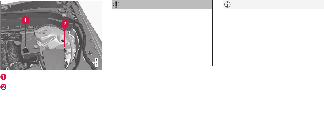
||
MAINTENANCE AND SERVICING
504
Positive connection point
Negative connection point
Only modern battery chargers with controlled
charging current should be used to charge the
start and support batteries. Quick charge func-
tions should not be used and could damage the
battery.
CAUTION
•The infotainment system's energy-saving
feature may not function correctly or at
all, and/or a message may be displayed if
a battery charger or jumper cables are
not connected properly.
•The negative terminal on the battery must
never be used to connect a jumper cable
or a battery charger. Only the ground
point on the chassis may be used.
NOTE
•The service life of the start battery is
shortened if it becomes discharged
repeatedly.
•The service life of the start battery is
affected by factors such as driving condi-
tions and climate. Extreme cold may also
further decrease the battery's start
capacity.
•Because the battery’s starting capacity
decreases with time, it may be necessary
to recharge it if the vehicle is not driven
for an extended period of time or if the
vehicle is usually only driven short dis-
tances.
•Driving for at least 15 minutes a week or
connecting the battery to a charger with
automatic maintenance charging will help
keep it in good operating condition.
•Keeping the start battery fully charged
will help maximize its service life.
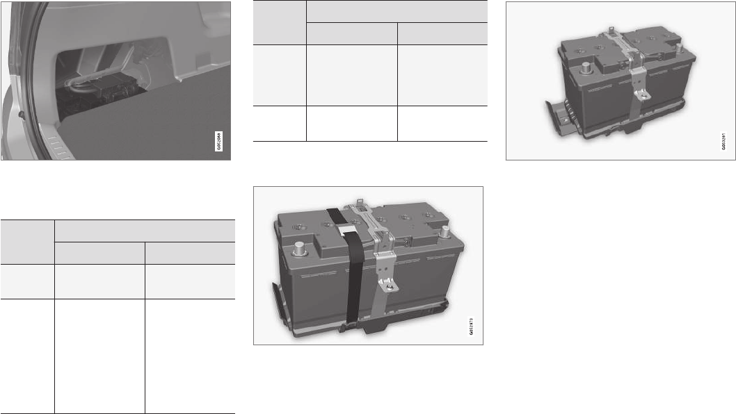
MAINTENANCE AND SERVICING
505
The start battery is located in the cargo compartment
There are two versions of the start battery,
depending on the vehicle model.
Battery
H7 AGM H8 AGM
Current
(V) 12 12
Cold
start
capacity
(Cold
Cranking
Amperes
- CCA)
(A)
800 850
Battery
H7 AGM H8 AGM
Dimen-
sions,
L×W×H
in. (mm)
12.4×6.9×7.5
(315×175×190)
13.9×6.9×7.5
(353×175×190)
Capacity
(Ah) 80 95
The H8 AGM is held in place by a strap. Ensure
that this strap is pulled taut.
H8 AGM battery with strap
There is no strap for the H7 AGM battery.
H7 AGM battery
•When replacing the start battery or support
battery an Absorbed Glass Mat (AGM) must
be used.
•When replacing the start battery, a new bat-
tery with the same specifications and dimen-
sions must be used. The battery should only
be replaced by a trained and qualified Volvo
service technician.
Related information
•Jump starting (p. 355)
•Support battery (p. 506)
•Battery symbols (p. 507)
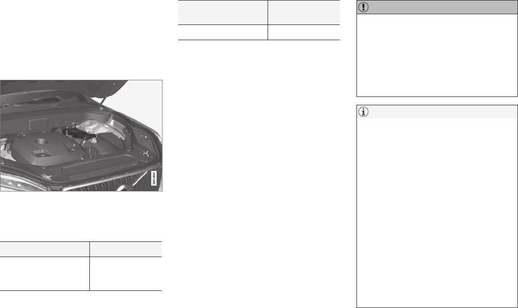
MAINTENANCE AND SERVICING
506
Support battery
Vehicles equipped with Start/Stop are equipped
with two 12-volt batteries.
In addition to a heavy-duty start battery, models
with Start/Stop also have a support battery that
provides extra current during the Start/Stop
function's start sequence.
The support battery is located in a box next to the spring
strut in the engine compartment
The following table shows the specifications for
the support battery:
Current (V) 12
Cold start capacity (Cold
Cranking Amperes -
CCA) (A)
170
Dimensions, L×W×H in.
(mm)
5.9×3.5×5.1
(150×90×130)
Capacity (Ah) 10
•When replacing the start battery or support
battery in a vehicle with Start/Stop, an
Absorbed Glass Mat (AGM) must be used.
•The greater the current consumption in the
vehicle, the more the generator has to oper-
ate and the battery is charged. This increases
fuel consumption.
•When the start battery's charge is below the
minimum permitted level, the Start/Stop
function will be disabled.
When the Start/Stop function is temporarily disa-
bled due to high current consumption:
•The engine will auto-start, even if the brake
pedal is depressed.
The support battery does not normally required
more service than the start battery. If questions
arise, consult a Volvo retailer or trained and quali-
fied Volvo service technician.
CAUTION
When connecting an external start battery or
a battery charger, the Start/Stop function may
be temporarily disabled if the negative termi-
nal on the vehicle's start battery is used to
connect an external start battery or a battery
charger. Only the negative connection point
in the engine compartment may be used as a
ground point.
NOTE
If the start battery is completely discharged
and the vehicle has no normal electrical func-
tions, and the engine is then started using an
auxiliary battery or battery charger, the
Start/Stop function will be activated. The
engine can then be auto-stopped but may not
auto-start again due to an insufficient charge
level in the start battery.
To help ensure auto-start, the start battery
should be charged first. At a temperature of
approx. 60 °F (15 °C), the battery should be
charged for at least 1 hour, preferably using
an external battery charger. At lower tempera-
tures, the battery should be charged for
3–4 hours.
If a charger is not available, it is advisable to
disable the Start/Stop function until the bat-
tery is sufficiently recharged.
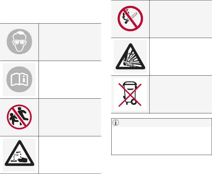
MAINTENANCE AND SERVICING
507
Related information
•Start battery (p. 503)
•Start/Stop (p. 370)
•Conditions for Start/Stop (p. 372)
Battery symbols
There are information and warning symbols on
the battery.
Wear protective goggles.
See the owner's manual for
additional information.
Keep batteries away from
children.
Batteries contain corrosive
acid.
Avoid smoking, open
flames, and/or sparks.
Risk of explosion
Recycle properly
NOTE
A used battery should be disposed of in an
environmentally responsible manner. Consult
your Volvo retailer or take the battery to a
recycling station.
Related information
•Start battery (p. 503)
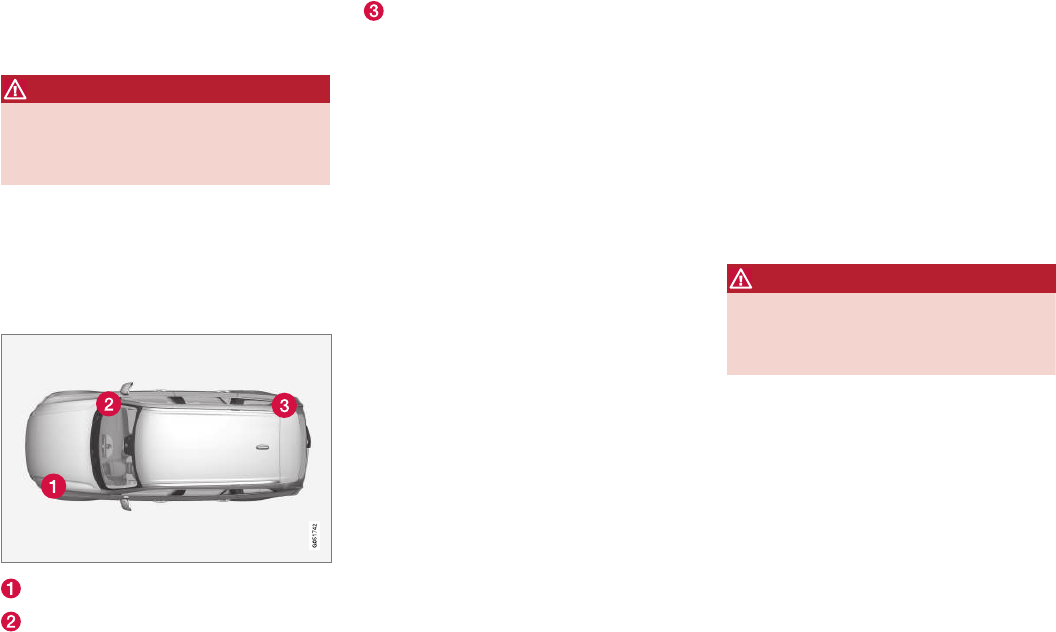
MAINTENANCE AND SERVICING
508
Fuses
The fuses help protect the vehicle's electrical
components from overloading or short circuits.
WARNING
Never use metal objects or fuses with higher
amperage than those stated on the lists of
fuses. Doing so could seriously damage or
overload the vehicle's electrical system.
If an electrical component fails to function, this
may be due to a blown fuse. If the same fuse
blows repeatedly, this indicates a problem with
the component, which should be inspected by a
trained and qualified Volvo service technician.
Location of the fuseboxes
Engine compartment
Under the glove compartment
Cargo compartment
Related information
•Replacing fuses (p. 508)
•Fuses in the cargo compartment (p. 517)
•Fuses in the engine compartment (p. 509)
•Fuses in the passenger compartment
(p. 513)
Replacing fuses
The fuses help protect the vehicle's electrical
components from overloading or short circuits.
Fuse replacement
1. See the list of fuse boxes for their locations.
2. Pull the fuse straight out and examine it from
the side to see if the curved metal wire in the
fuse is intact.
3. If the wire is broken, insert a new fuse of the
same color and amperage (written on the
fuse).
WARNING
Never use metal objects or fuses with higher
amperage than those stated on the following
pages. Doing so could seriously damage or
overload the vehicle's electrical system.
Related information
•Fuses (p. 508)
•Fuses in the cargo compartment (p. 517)
•Fuses in the engine compartment (p. 509)
•Fuses in the passenger compartment
(p. 513)
MAINTENANCE AND SERVICING
}}
509
Fuses in the engine compartment
The fuses in the engine compartment help pro-
tect electrical components such as engine and
brake functions.
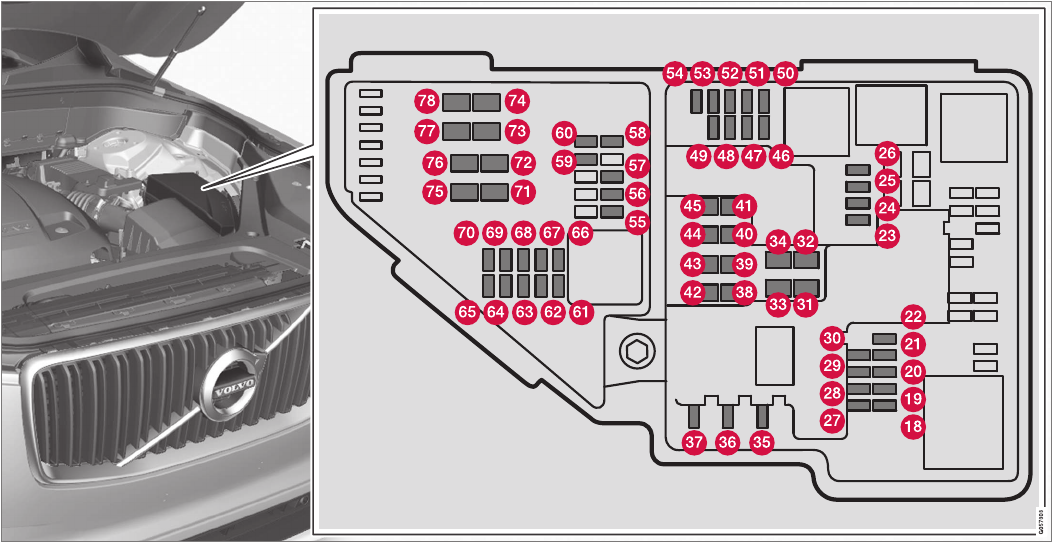
||
MAINTENANCE AND SERVICING
510
There is a fuse removal tool on the inside of the
fuse box cover.
Positions
There is a decal on the inside of the cover with a
list of fuses.

MAINTENANCE AND SERVICING
}}
* Option/accessory, for more information, see Introduction. 511
•Fuses 18–30, 35–37, 46–54 and 55–70
are called "Micro".
•Fuses 31–34, 38–45 and 71–78 are called
"MCase" and should only be replaced by a
trained and qualified Volvo service technician.
Function A
– –
– –
– –
– –
– –
Front USB socket*5
12-volt socket in the front tun-
nel console
15
12-volt socket on the rear side
of the tunnel consoleA
12-volt socket in the tunnel con-
sole between the rear seats B
15
12-volt socket in the cargo com-
partment
USB sockets for iPad holdersB
15
– –
Function A
– –
– –
– –
Heated windshield*, driver side Shunt
Heated windshield*, driver side 40
Headlight washers*25
Windshield washer 25
– –
Horn 20
Alarm siren*5
Brake system control module
(valves, parking brake)
40
Windshield wipers 30
Tailgate window washer 25
Heated windshield*, passenger
side
40
– –
Function A
Brake system control module
(ABS pump)
40
– –
Heated windshield*, passenger
side
Shunt
Feed when ignition is switched
on to: engine control module,
transmission components, elec-
trical power steering, central
electrical module;
Brake system control module
5
–
Exterior sound
–
5
Passenger side headlight 7.5
– –
– –
Battery connections control
module
–
5
–
Air bags; Occupant Weight Sen-
sor (OWS)
5
Driver side headlight 7.5

||
MAINTENANCE AND SERVICING
512
Function A
Accelerator pedal sensor 5
Transmission control module
Gear selector control module
15
Engine control module 5
– –
– –
– –
– –
Engine control module; Turbo-
charger valve
20
Solenoids; Valves; Engine cool-
ing system thermostat
10
Vacuum regulators; Valve 7.5
Spoiler shutter control module;
Radiator shutter control module;
Fuel leakage detection
5
– –
Heated oxygen sensors (front
and rear)
15
Function A
Oil pump solenoid; A/C mag-
netic coupling; heated oxygen
sensor (center)
15
– –
Engine control module 20
Ignition coil; Spark plugs 15
– –
– –
– –
– –
– –
– –
Starter motor Shunt
Starter motor 40
ANot XC90 Excellence
BXC90 Excellence
Related information
•Fuses (p. 508)
•Replacing fuses (p. 508)
MAINTENANCE AND SERVICING
}}
513
Fuses in the passenger
compartment
The fuses in the passenger compartment help
protect electrical components such as the 120-
volt socket, displays and door modules.
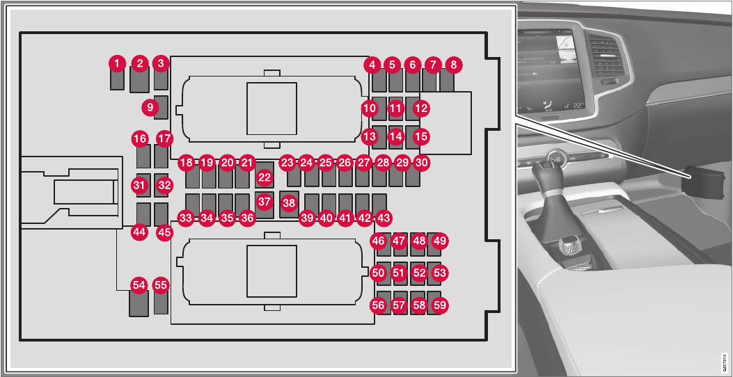
||
MAINTENANCE AND SERVICING
514
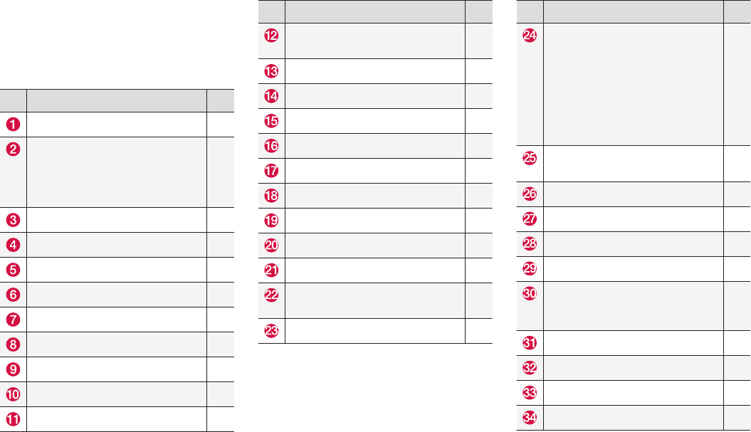
MAINTENANCE AND SERVICING
}}
* Option/accessory, for more information, see Introduction. 515
Positions
•Fuses 1, 3–21, 23–36, 39–53 and 55–59
are called "Micro".
•Fuses 2, 22, 37–38 and 54 are called
"MCase" and should only be replaced by a
trained and qualified Volvo service technician.
Function A
– –
120-volt socket on the rear side of
the tunnel console*
120-volt socket between the rear
seatsA
30
– –
Alarm system movement sensorB5
Media player 5
Instrument panel 5
Center console buttons 5
Sun sensor 5
– –
– –
Steering wheel module 5
Function A
Module for start knob and parking
brake
5
Heated steering wheel* module 15
– –
– –
– –
– –
Climate system control module 10
– –
On-board diagnostics (OBDII) 10
Center display 5
Climate system blower module
(front)
40
– –
Function A
Instrument lighting; Courtesy light-
ing; Rearview mirror auto-dim func-
tion; Rain and light sensor; Rear
tunnel console keypad*A; Power
front seats*; Power rear seatsA;
Display for rear seat convenience
functionsA; Rear seat massage
functionA
7.5
Control module for driver support
functions
5
Panorama roof and sun shade*20
Head-up display*5
Courtesy lighting 5
– –
Ceiling console display (seat belt
reminder, front passenger side air-
bag indicator)
5
– –
Humidity sensor 5
Rear passenger-side door module 20
Fuses in the cargo compartment 10

||
MAINTENANCE AND SERVICING
* Option/accessory, for more information, see Introduction.
516
Function A
Internet connection control module;
Volvo On Call control module
5
Rear driver-side door module 20
Infotainment control module
(amplifier)
40
Climate system blower module
(rear)
40
Multi-band antenna module 5
Front seat massage function 5
– –
Tailgate window wiper 15
Fuel pump control module 15
– –
– –
Driver side seat heating*15
Passenger side seat heating*15
Coolant pump 10
– –
Front driver-side door module 20
Function A
Active chassis control module*20
– –
Sensus control module 10
– –
– –
Front passenger-side door module 20
Display for rear seat convenience
functionsA
5A
– –
Circuit breaker for fuses 53 and 58 15
AXC90 Excellence.
BCertain markets only.
Related information
•Fuses (p. 508)
•Replacing fuses (p. 508)
MAINTENANCE AND SERVICING
}}
* Option/accessory, for more information, see Introduction. 517
Fuses in the cargo compartment
The fuses in the cargo compartment help pro-
tect electrical components such as power
seats*, airbags and seat belt tensioners.
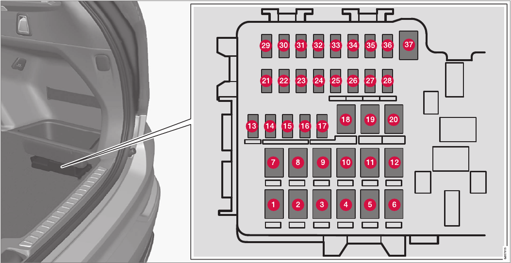
||
MAINTENANCE AND SERVICING
518
The fuse box is under the storage compartment on the right side
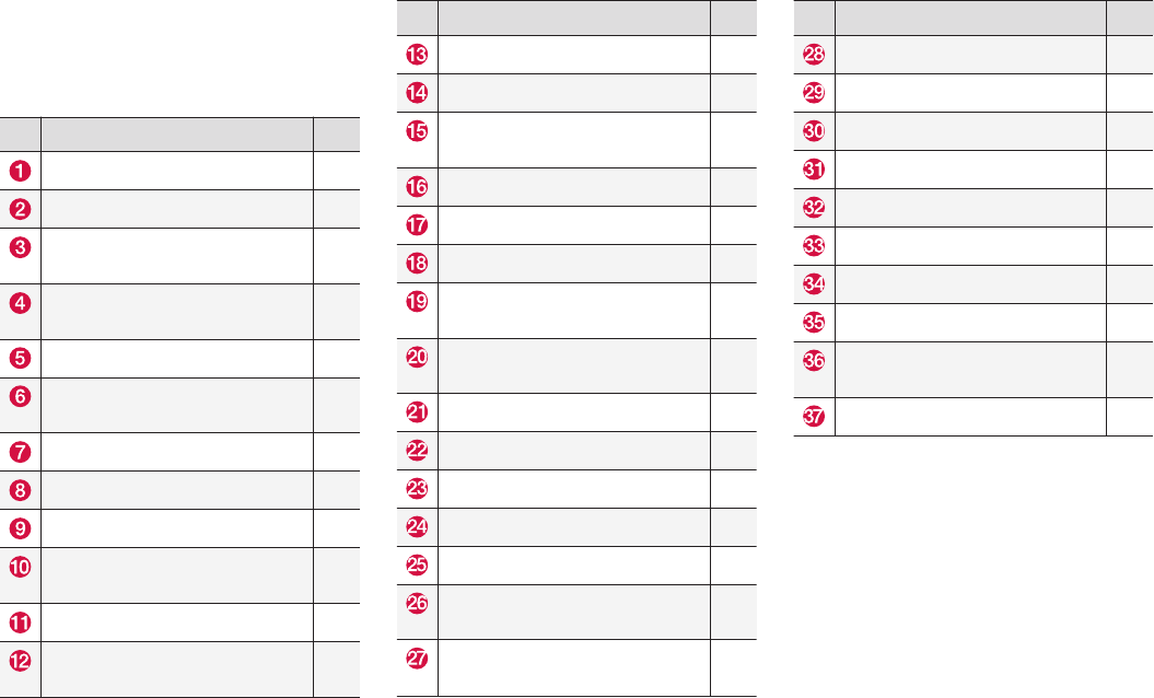
MAINTENANCE AND SERVICING
* Option/accessory, for more information, see Introduction. 519
Positions
•Fuses 13–17 and 21–36 are called "Micro".
•Fuses 1–12, 18–20 and 37 are called
"MCase" and should only be replaced by a
trained and qualified Volvo service technician.
Function A
Heated rear window 30
Power rear seat (driver side)A20A
Pneumatic suspension* compres-
sor
40
Rear auxiliary electric heater (pas-
senger side)
30
– –
Rear auxiliary electric heater
(driver side)*
30
Power rear seat (passenger side)A20A
– –
Power tailgate*25
Power front seat (passenger side)*
module
20
Trailer hitch* control module 40
Seat belt tensioner module (pas-
senger side)
40
Function A
Internal relay windings 5
– –
Foot movement detection module
for opening the power tailgate*
5
– –
– –
Trailer hitch* control module 25
Power front seat (driver seat*
module
20
Seat belt tensioner module (driver
side)
40
Parking camera*5
– –
– –
Ionic air cleanerA5A
– –
Airbag and seat belt tensioner
modules
5
Cooler; heated/cooled cup holder
(rear)A
10A
Function A
Heated rear seat (driver side)*15
– –
Blind Spot Information (BLIS)*5
– –
Seat belt tensioner modules 5
Emission system actuator 5
– –
All Wheel Drive control module*15
Heated rear seat (passenger
side)*
15
– –
AXC90 Excellence.
Related information
•Replacing fuses (p. 508)
•Fuses (p. 508)
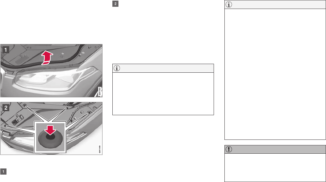
MAINTENANCE AND SERVICING
520
Replacing bulbs
The halogen headlight bulbs can be replaced by
the owner.
Before the bulbs can be replaced, that plastic
covering over the headlight housing has to be
removed.
To do so:
Lift the rubber strip by pressing in toward the
engine compartment.
Release the pins in the plastic covering's
four clips by pressing them down with a
screwdriver or similar object and remove the
covering.
The turn signal, high/low beam, Daytime Running
Light and parking light bulbs will be accessible
when the plastic covering has been removed.
Put the covering back in place in the reverse
order.
NOTE
The pins in the clips have to be pressed back
completely before the clips are placed in the
plastic covering.
When the covering is put back in place, the
pins must be pressed so that their upper sur-
face is flush with the surface of the clip.
NOTE
•For information regarding any bulbs not
mentioned in this section, please contact
your Volvo retailer or a trained and
authorized Volvo service technician.
•Always switch off the ignition before star-
ting to replace a bulb.
•If an error message remains in the dis-
play after a faulty bulb has been replaced,
contact an authorized Volvo workshop.
•Condensation may form temporarily on
the inside of the lenses of exterior lights
such as headlights, fog lights, or taillights.
This is normal and the lights are
designed to withstand moisture. Normally,
condensation will dissipate after the
lights have been on for a short time.
•The optional Active Bending Light bulbs
contain trace amounts of mercury. These
bulbs should always be disposed of by a
trained and qualified Volvo service techni-
cian.
CAUTION
Never touch the glass of bulbs with your fin-
gers. Grease and oils from your fingers vapor-
ize in the heat and will leave a deposit on the
reflector, which will damage it.
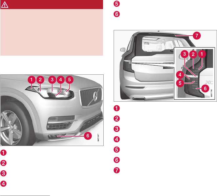
MAINTENANCE AND SERVICING
521
WARNING
•The ignition should be switched off com-
pletely (be in ignition mode 0) when
replacing bulbs.
•If the engine has been running just prior
to replacing bulbs in the headlight hous-
ing, please keep in mind that components
in the engine compartment will be hot.
Front bulbs (vehicles with halogen
headlights)
Side marker light
Low beam
High beam
Parking light/Daytime Running Light
Turn signal
Fog light with corner illumination (LED)
Taillight bulbs
Brake light (LED)
Side marker light (LED)
Backup light2
Taillight (LED)
Turn signal (LED)
Fog light (LED)
High-mounted brake light (LED)
Related information
•Bulb specifications (p. 525)
•Removing the rectangular headlight cover
(p. 522)
•Replacing parking light bulbs (p. 524)
•Replacing front turn signal bulbs (p. 524)
•Replacing High Beam headlight bulbs
(p. 523)
•Replacing low beam headlight bulbs
(p. 522)
2Must be replaced by a trained and qualified Volvo service technician.
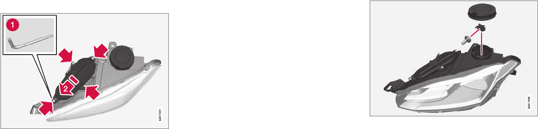
MAINTENANCE AND SERVICING
522
Removing the rectangular headlight
cover
Most of the bulbs in the headlight housing can
be accessed when the rectangular cover has
been removed.
Before the rectangular cover can be removed, the
plastic covering must be removed, see the article
"Replacing bulbs" for information.
1. Loosen the cover's four screws with a T20
Torx screwdriver (1) but do not remove them
completely (turning them 3–4 turns is
enough).
2. Push the cover to the side.
3. Remove the cover.
Put the cover back in place in the reverse order.
Related information
•Replacing bulbs (p. 520)
Replacing low beam headlight bulbs
On models with halogen headlights, the low
beam headlight bulb can be replaced by the
owner.
Before the bulb can be replaced, the plastic cov-
ering over the headlight housing has to be
removed, see the article "Replacing bulbs."
1. Remove the round rubber cover from the
headlight housing.
2. Remove the bulb by turning the bulb holder
upward and then pulling it straight out.
3. Carefully pry the plastic sleeve by the con-
nector's locking lug to release it.
4. Remove the connector from the bulb.
5. Insert a new bulb.
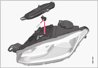
MAINTENANCE AND SERVICING
523
6. Insert the bulb in the socket and turn down-
ward. It can only be inserted in one way.
7. Put the rubber cover back into place.
Related information
•Replacing bulbs (p. 520)
•Bulb specifications (p. 525)
Replacing High Beam headlight
bulbs
On models with halogen headlights, the High
Beam headlight bulb can be replaced by the
owner.
Before the bulb can be accessed, the headlight
housing's rectangular cover must be removed,
see the article "Removing the rectangular head-
light cover."
1. Remove the bulb by turning the bulb holder
upward and then pulling it straight out.
2. Carefully pry the plastic sleeve by the con-
nector's locking lug to release it.
3. Remove the connector from the bulb.
4. Insert a new bulb.
5. Insert the bulb in the socket and turn down-
ward. It can only be inserted in one way.
Related information
•Removing the rectangular headlight cover
(p. 522)
•Bulb specifications (p. 525)
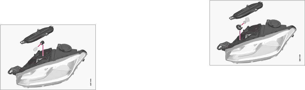
MAINTENANCE AND SERVICING
524
Replacing parking light bulbs
On models with halogen headlights, the front
parking light bulb can be replaced by the owner.
Before the bulb can be accessed, the headlight
housing's rectangular cover must be removed,
see the article "Removing the rectangular head-
light cover."
Remove the high beam bulb first by turning the
bulb holder upward and then pulling it straight
out. This makes it easier to access the parking
light bulb.
1. Pull the bulb holder straight out.
2. Remove the bulb by pulling it straight out.
3. Insert a new bulb.
4. Insert the bulb holder in the socket and
press it into place.
5. If the high beam bulb was removed, insert
the bulb in the socket and turn downward. It
can only be inserted in one way.
Related information
•Replacing bulbs (p. 520)
•Bulb specifications (p. 525)
•Removing the rectangular headlight cover
(p. 522)
Replacing front turn signal bulbs
On models with halogen headlights, the front
turn signal bulb can be replaced by the owner.
Before the bulb can be accessed, the headlight
housing's rectangular cover must be removed,
see the article "Removing the rectangular head-
light cover".
1. Press the retaining catches together and pull
the bulb holder straight out.
2. The bulb holder and bulb must be replaced
as one unit.
3. Press the new bulb holder into the socket.
Related information
•Removing the rectangular headlight cover
(p. 522)
•Replacing bulbs (p. 520)
•Bulb specifications (p. 525)

MAINTENANCE AND SERVICING
525
Bulb specifications
The following specifications apply to models
equipped with halogen headlights. If other bulbs
need to be replaced, contact a trained and quali-
fied Volvo service technician.
Function [W]AType
Low beam 55 H11
High Beam 65 H9
Turn signal 24 PY24W
Daytime running light/
parking light
21/5 W21/5W
AWatt
Related information
•Replacing bulbs (p. 520)

MAINTENANCE AND SERVICING
* Option/accessory, for more information, see Introduction.
526
Hoisting the vehicle
When the vehicle is hoisted, the jack or garage
lift must be positioned correctly under the vehi-
cle.
For vehicles equipped with leveling control*, if it is
also equipped with the optional pneumatic sus-
pension, this must be deactivated before the
vehicle is hoisted. This is done from the center
display:
1. Tap Settings in Top view.
2. Tap My Car Suspension .
3. Select Deactivate Suspension & Leveling
Control.
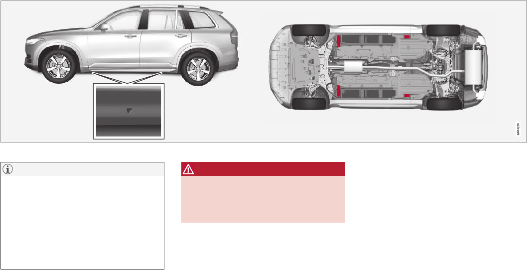
MAINTENANCE AND SERVICING
527
Location of the jack attachment points (triangles)/lifting points (red areas)
NOTE
The jack provided with your vehicle is
intended to be used only in temporary situa-
tions such as changing wheels in the event of
a flat tire. Only the jack that came with your
particular model should be used to lift the
vehicle. If the vehicle needs to be lifted more
frequently or for a prolonged period, using a
garage jack or hoist is recommended. Always
follow this device’s instructions for use.
WARNING
•Ensure that the jack is positioned so that
the vehicle cannot slide off it.
•Always use axle stands or similar struc-
tures.
Related information
•Removing a wheel (p. 486)
•Installing a wheel (p. 487)
•Jack (p. 484)
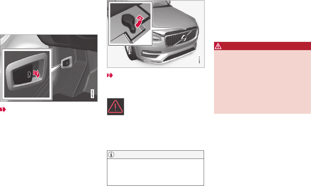
MAINTENANCE AND SERVICING
528
Opening and closing the hood
The hood is opened by releasing it from the pas-
senger compartment and then by using the han-
dle under the front edge of the hood.
Opening
With the hood completely closed, pull the
control (located to the left of the brake
pedal).
Turn the handle under the front edge of the
hood counterclockwise to release it from the
lock and lift.
Warning–hood not closed
When the hood lock has been com-
pletely released, this symbol and a
graphic will illuminate in the instrument
panel and an audible signal will be
given. If the vehicle begins to roll, the audible sig-
nal will be repeated several times.
For additional information, see also the article
"Door and seat belt reminders."
NOTE
If the warning symbol remains on or if the
audible signal is given even if the hood is
completely closed and locked, consult a
trained and qualified Volvo service technician.
Closing
1. Press down the hood until it begins to close
due to its own weight.
2. When the handle under the front edge of the
hood is in the lock, press down on the hood
to close it completely.
WARNING
•Be sure the hood is completely unob-
structed while it is being closed.
•Check that the hood locks properly when
closed. It must audibly lock on both sides.
•Never drive if the hood is not completely
closed and locked.
•While driving, if there are any indications
that the hood is not locked in the closed
position, stop safely as soon as possible
and close it completely.
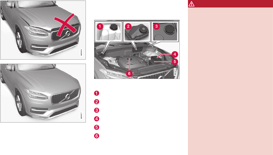
MAINTENANCE AND SERVICING
}}
529
Hood completely closed
Related information
•Engine compartment overview (p. 529)
•Door and seat belt reminders (p. 63)
Engine compartment overview
The engine compartment overview shows some
maintenance points.
The layout of the engine compartment may differ slightly
from model to model
Coolant expansion tank
Brake fluid reservoir
Washer fluid reservoir
Relay/fuse box
Air cleaner
Engine oil filler cap
WARNING
•The cooling fan (located at the front of
the engine compartment, behind the radi-
ator) may start or continue to operate (for
up to 6 minutes) after the engine has
been switched off.
•Engine cleaning should only be done by a
workshop. If engine cleaning agents are
used when the engine has been running,
there may a fire risk.
•Before performing any operations in the
engine compartment, the ignition should
always be completely switched off (in
mode 0) and there should be no remote
keys in the passenger compartment. The
gear selector should be in the P (park)
position. If the engine has been running,
wait until it has cooled before touching
any components in the engine compart-
ment.
•The distributor ignition system operates
at very high voltages. Special safety pre-
cautions must be followed to prevent
injury. Always turn the ignition off when
replacing distributor ignition components
e.g. plugs, coil, etc.
•Do not touch any part of the distributor
ignition system while the engine is run-
ning. This may result in unintended move-
ments and body injury.
||
MAINTENANCE AND SERVICING
530
Related information
•Ignition modes (p. 360)
•Opening and closing the hood (p. 528)
•Refilling the windshield washer fluid reservoir
(p. 534)
Engine oil
The correct oil must be used for the stated oil
change (service) intervals to apply.
Volvo recommends:
CAUTION
•Not checking the oil level regularly can
result in serious engine damage if the oil
level becomes too low.
•Oil that is lower than the specified quality
can damage the engine.
•Volvo does not recommend the use of oil
additives.
•Always add oil of the same type and vis-
cosity as already used.
•Oil changes should be carried out by a
trained and qualified Volvo service techni-
cian.
•Using oil of higher than the specified
quality is permitted and may be neces-
sary for demanding driving.
Also, refer to the Warranty and Service Records
information booklet for information on oil change
intervals and oil specifications.
Related information
•Checking and refilling engine oil (p. 531)
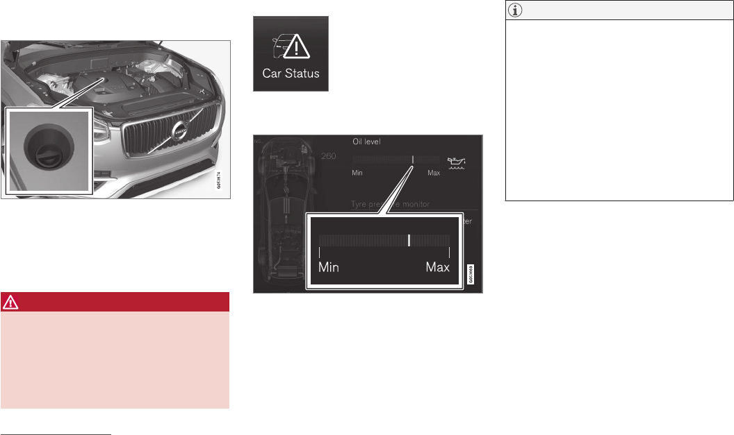
MAINTENANCE AND SERVICING
531
Checking and refilling engine oil
The oil level is checked electronically.
Oil filler cap3
It may be necessary to top up engine oil between
regularly scheduled services.
No action is necessary until a message is dis-
played in the instrument panel.
WARNING
•Do not allow oil to spill onto or come into
contact with hot exhaust pipe surfaces.
•If Engine oil level Service required is
displayed, have the vehicle checked by a
trained and qualified Volvo service techni-
cian. The oil level may be too high.
Checking the oil level
The oil level can be checked in
the center display when the
engine is not running.
From the center display's
Home view, swipe the screen
from right to left to open App
view. Tap Car status and then tap Status to
show the oil level.
Oil level graphic in the center display
The oil level should be checked at regular inter-
vals, particularly during the period up to the first
scheduled maintenance service.
If the oil level sensor indicates that the level is
too low, using the correct oil, top up with the
amount of oil indicated as soon as possible.
NOTE
•The system cannot detect changes in the
oil level immediately. The vehicle must be
driven approximately 20 miles (30 km) or
have been parked on level ground with
the engine off for 5 minutes before the
oil level reading will be correct.
•If the necessary conditions are not met
for checking the oil level electronically
(time interval after the engine was
switched off, if the vehicle is parked on
an incline, etc.), No values available will
be displayed. This does not indicate a
problem with the oil level sensor.
Related information
•Engine oil (p. 530)
•Ignition modes (p. 360)
3Models with an electronic oil level sensor do not have a dipstick.
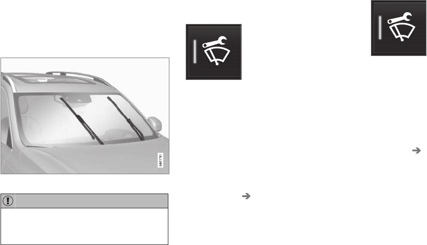
MAINTENANCE AND SERVICING
532
Windshield wipers in the service
position
The windshield wiper blades must be in the verti-
cal (service) position for replacement, washing
or to lift them away from the windshield when
e.g., removing ice or snow.
Wipers in the service position
CAUTION
Be sure the wiper blades are not frozen in
position before attempting to move them to
the service position.
Putting the windshield wipers in the
service position
The service position can be activated while the
vehicle is stationary and the wipers are not acti-
vated.
The service position can be activated in two ways
from the center display:
Via Function view
–From Function view, tap the Wiper Service
Position button. The indicator light in the
button will illuminate when the service posi-
tion is activated.
> The windshield wipers will move to the
vertical position.
Via Settings
1. Tap Settings in the center display's Top
view.
2. Tap My Car Wipers
3. Tap the Wiper Service Position box.
> The windshield wipers will move to the
vertical position.
Deactivating service position
The service position can be deactivated in two
ways from the center display:
Via Function view
–From Function view, tap the Wiper Service
Position button. The indicator light in the
button will go out when the service position
is deactivated.
Via Settings
1. Tap Settings in the center display's Top
view.
2. My Car Wipers
3. Tap the Wiper Service Position to deselect
the box.
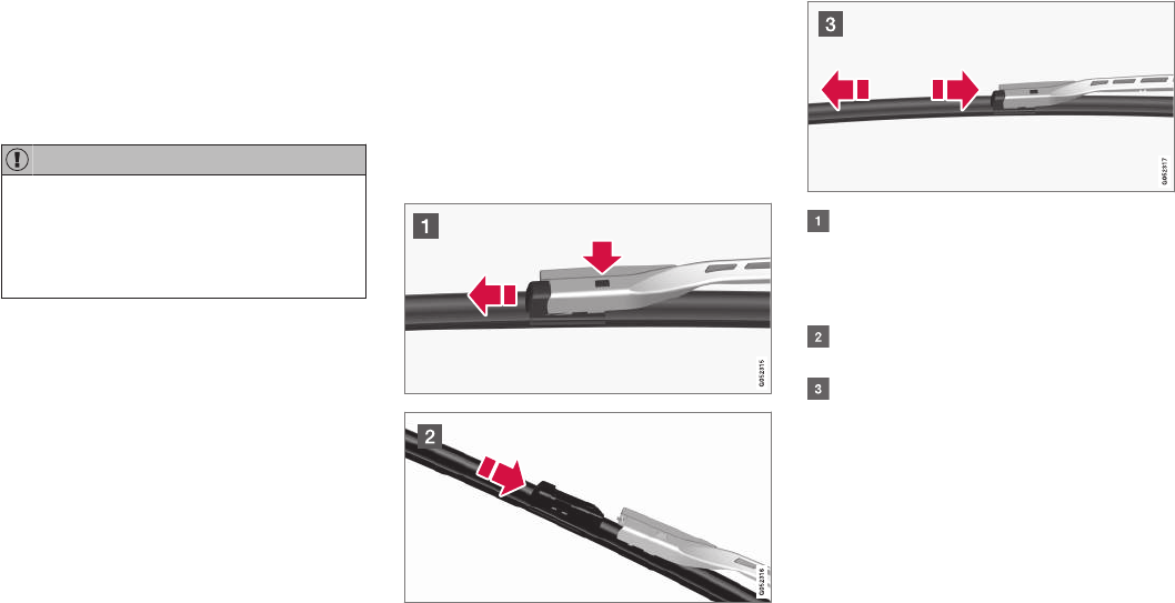
MAINTENANCE AND SERVICING
}}
533
The wipers will also leave the service position if:
•The wipers are activated.
•The windshield/headlight washers are acti-
vated.
•The rain sensor is activated.
CAUTION
If the wiper arms have been folded out from
the windshield while in the service position,
fold them back against the windshield before
returning the wipers to the normal position to
help avoid scratching the paint on the hood.
Related information
•Replacing wiper blades (p. 533)
•Using the windshield wipers (p. 152)
Replacing wiper blades
The wiper blades should be replaced regularly
for best effect.
The windshield wiper blades must be in the verti-
cal (service) position for replacement, washing
or to lift them away from the windshield when
e.g., removing ice or snow.
Replacing the windshield wiper blades
With the wipers in the service position, fold
out the wiper arm from the windshield. Press
the button on the wiper blade attachment
and pull the wiper blade straight out, parallel
with the wiper arm.
Slide in the new wiper blade until it clicks
into place.
Check that the blade is securely in place.
4. Press the wipers back against the wind-
shield.
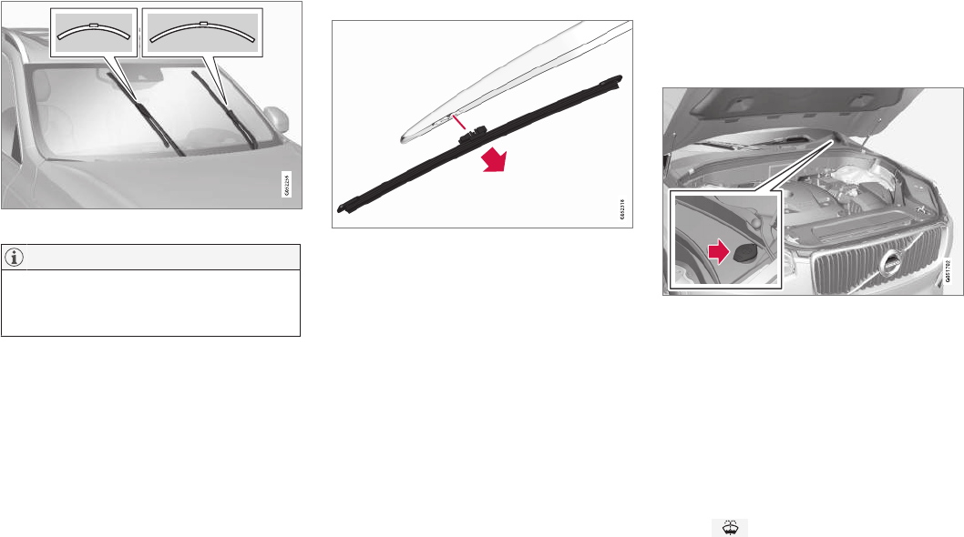
||
MAINTENANCE AND SERVICING
* Option/accessory, for more information, see Introduction.
534
The windshield wiper blades are different lengths
NOTE
The windshield wiper blades are different
lengths. The blade on the driver’s side is
longer than the one on the passenger side.
Cleaning
Keeping the windshield/tailgate window and
wiper blades clean helps improve visibility and
prolongs the service life of the wiper blades.
Clean the wiper blades with a stiff-bristle brush
and lukewarm soap solution or car washing
detergent.
Replacing the tailgate wiper blade
1. Fold the wiper arm outward.
2. Grasp the inner section of wiper blade (at the
arrow).
3. Turn the wiper blade counterclockwise to use
one end as a lever to help release it from the
wiper arm.
4. Press the new wiper blade until it clicks into
place and check that it seats securely.
5. Fold the wiper arm back toward the tailgate
window.
Related information
•Windshield wipers in the service position
(p. 532)
•Refilling the windshield washer fluid reservoir
(p. 534)
Refilling the windshield washer fluid
reservoir
Washer fluid helps keep the windshield and
headlights clean.
The windshield and headlight washers* share a
common reservoir. Open the blue cap to refill
washer fluid (see the illustration for the location
of the reservoir).
During cold weather, the reservoir should be filled
with windshield washer solvent containing anti-
freeze. Use Volvo Original Washer Fluid or the
equivalent with a recommended pH value
between 6 and 8 in a 1:1 solution.
When there is approx. 1 qt (1 liter) of washer
fluid remaining in the reservoir, a text message
and the symbol will be displayed in the
instrument panel.

MAINTENANCE AND SERVICING
}}
535
Related information
•Opening and closing the hood (p. 528)
•Engine compartment overview (p. 529)
Cleaning the exterior
The vehicle should be washed at regular inter-
vals since dirt, dust, insects and tar spots
adhere to the paint and may cause damage. To
help prevent corrosion, it is particularly important
to wash the car frequently in the wintertime.
Hand washing
The following points should be kept in mind when
washing and cleaning the car:
•Avoid washing your car in direct sunlight.
Doing so may cause detergents and wax to
dry out and become abrasive. To avoid
scratching, use lukewarm water to soften the
dirt before you wash with a soft sponge, and
plenty of sudsy water.
•Bird droppings: Remove from paintwork as
soon as possible. Otherwise the finish may
be permanently damaged.
•A car washing detergent can be used to
facilitate the softening of dirt and oil.
•Dry the car with a clean chamois and
remember to clean the drain holes in the
doors and rocker panels.
•Tar spots can be removed with tar remover
after the car has been washed.
•A stiff-bristle brush and lukewarm soapy
water can be used to clean the wiper blades.
Frequent cleaning of the windshield and
wiper blades improves visibility considerably
and also helps prolong the service life of the
wiper blades.
•Wash off the dirt from the underside (wheel
housings, fenders, etc).
•In areas of high industrial fallout, more fre-
quent washing is recommended.
CAUTION
•During high pressure washing, the spray
mouthpiece must never be closer to the
vehicle than 13" (30 cm). Do not spray
into the locks.
•Dirt, snow, etc., on the headlights can
reduce lighting capacity considerably.
Clean the headlights regularly, for exam-
ple when refueling.
Special laminated panoramic roof cau-
tions:
•Always close the laminated panoramic
roof and sun shade before washing your
vehicle.
•Never use abrasive cleaning agents on
the laminated panoramic roof.
•Never use wax on the rubber seals
around the laminated panoramic roof.
NOTE
When washing the car, remember to remove
dirt from the drain holes in the doors and sills.
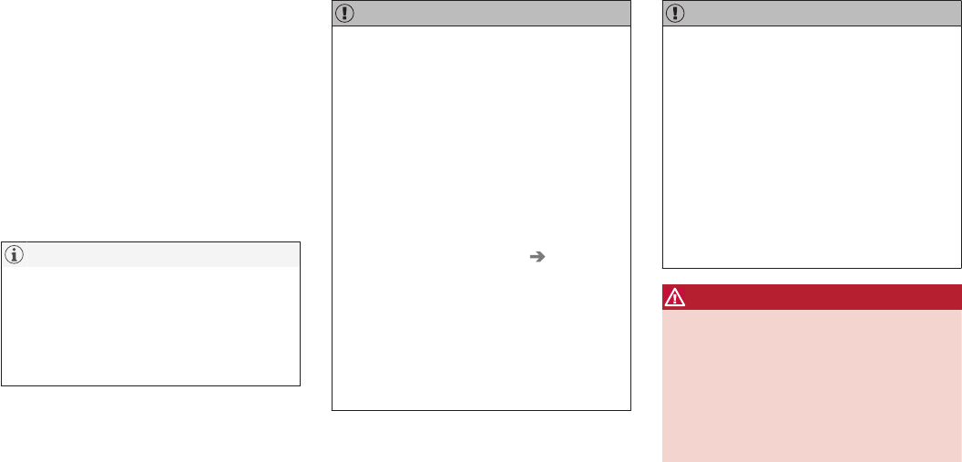
||
MAINTENANCE AND SERVICING
536
Automatic car washes
•We do NOT recommend washing your car in
an automatic wash during the first few
months (because the paint will not have
hardened sufficiently).
•An automatic wash is a simple and quick way
to clean your car, but it is worth remembering
that it may not be as thorough as when you
yourself go over the car with sponge and
water. Keeping the underbody clean is most
important, especially in the winter. Some
automatic washers do not have facilities for
washing the underbody.
NOTE
Condensation may form temporarily on the
inside of the lenses of exterior lights such as
headlights or taillights. This is normal and the
lights are designed to withstand moisture.
Normally, condensation will dissipate after the
lights have been on for a short time.
CAUTION
When using an automatic car wash in which
the vehicle has to be able to roll freely, the
auto-hold brake function must be deactivated.
If this is not done, the brakes will automati-
cally be applied when the vehicle is stationary.
To deactivate this function:
1. Drive the vehicle into the car wash
2. Turn off the auto-hold function using the
control on the center console
3. Turn off the parking brake's automatic
function in the center display's Top view
(tap Settings, tap My Car Electric
Parking Brake and deselect Auto
Activate Parking Brake)
4. Put the gear selector in N
5. Switch off the ignition by turning the start
knob to STOP and holding it in this posi-
tion for at least 4 seconds
The vehicle will then be able to roll freely.
CAUTION
•Before driving into an automatic car
wash, turn off the optional rain sensor to
avoid damaging the windshield wipers.
•Make sure that side view mirrors, auxiliary
lamps, etc, are secure, and that any
antenna(s) are retracted or removed. Oth-
erwise there is risk of the machine dis-
lodging them.
•Chromed wheels: Clean chrome-plated
wheels using the same detergents used
for the body of the vehicle. Aggressive
wheel-cleaning agents can permanently
stain chrome-plated wheels.
WARNING
•When the vehicle is driven immediately
after being washed, apply the brakes,
including the parking brake, several times
in order to remove any moisture from the
brake linings.
•Engine cleaning agents should not be
used when the engine is warm. This con-
stitutes a fire risk.
Exterior components
Volvo recommends the use of special cleaning
products, available at your Volvo retailer, for
cleaning colored plastic, rubber, or ornamental
components such as chromed strips on the exte-

MAINTENANCE AND SERVICING
}}
* Option/accessory, for more information, see Introduction. 537
rior of your vehicle. The instructions for using
these products should be followed carefully. Sol-
vents or stain removers should not be used.
CAUTION
•Avoid waxing or polishing plastic or rub-
ber components
•Polishing chromed strips can wear away
or damage the surface
•Polishes containing abrasive substances
should not be used
Related information
•Paint damage (p. 540)
•Corrosion protection (p. 540)
•Polishing and waxing (p. 542)
•Windshield wipers in the service position
(p. 532)
Cleaning the interior
Only use cleaning agents and car care products
recommended by Volvo. Clean regularly and fol-
low the instructions included with the car care
product.
CAUTION
•Under no circumstances should gasoline,
naphtha or similar cleaning agents be
used on the plastic or the leather since
these can cause damage.
•Take extra care when removing stains
such as ink or lipstick since the coloring
can spread.
•Use solvents sparingly. Too much solvent
can damage the seat padding.
•Start from the outside of the stain and
work toward the center.
•Sharp objects (e.g. pencils or pens in a
pocket) or Velcro fasteners on clothing
may damage the textile upholstery.
•Clothing that is not colorfast, such as
new jeans or suede garments, may stain
the upholstery.
Fabric upholstery and ceiling liner
Clean with soapy water or a detergent. For more
difficult spots caused by oil, ice cream, shoe pol-
ish, grease, etc., use a clothing/fabric stain
remover. Consult your Volvo retailer.
Leather* care
Volvo's leather upholstery is manufactured with a
protectant to repel soiling. Over time, sunlight,
grease and dirt can break down the protection.
Staining, cracking, scuffing, and fading can result.
Volvo offers an easy-to-use, non-greasy leather
care kit formulated to clean and beautify your
vehicle's leather, and to renew the protective
qualities of its finish. The cleaner removes dirt
and oil buildup. The light cream protectant
restores a barrier against soil and sunlight.
Volvo also offers a special leather softener that
should be applied after the cleaner and protec-
tant. It leaves leather soft and smooth, and
reduces friction between leather and other fin-
ishes in the vehicle.
Volvo recommends cleaning, protecting and con-
ditioning your vehicle's leather two to four times a
year. Ask your Volvo retailer about Leather Care
Kit 951 0251 and Leather Softener 943 7429.
Cleaning leather upholstery
1. Pour leather cleaner on a damp sponge and
squeeze it until the cleaner foams.
2. Apply the foam to the stain by moving the
sponge with circular movements.
3. Dampen the stain thoroughly with the
sponge. Let the sponge absorb the stain, do
not rub.
4. Dry the stain with soft paper towels or a
towel, and allow the leather to dry completely.

||
MAINTENANCE AND SERVICING
* Option/accessory, for more information, see Introduction.
538
Protecting leather upholstery
1. Put a small amount of protectant cream on a
cloth and apply a thin coating of cream to the
upholstery with light circular movements.
2. Allow the leather to dry for 20 minutes.
This will help the leather resist staining and pro-
tect against sunlight's harmful UV rays.
Cleaning a leather-covered steering
wheel
•Remove soil, dust, etc., with a damp sponge
and a neutral soap solution.
•Leather should be allowed to breath. Never
cover the steering wheel with a plastic pro-
tector.
•Volvo recommends cleaning, protecting and
conditioning the steering wheel with Volvo's
Leather Care Kit 951 0251 and Leather
Softener 943 7429.
If there are stains on the steering wheel:
Type 1 (ink, wine, coffee, milk, sweat or blood)
–Use a soft cloth or sponge. Wipe the wheel
with a solution with 5% ammonia. For blood
stains, mix approx. 1 cup (2 dl) of water and
one ounce (25g) of salt and wipe the stain.
Type 2 (fat, oil, sauces, or chocolate)
1. Same procedure as for type I stains.
2. Finish by rubbing the wheel with absorbent
paper or a towel.
Type 3 (dry soil or dust)
1. Remove the soil/dust with a soft brush.
2. Same procedure as for type I stains.
CAUTION
Sharp objects, such as rings, could damage
the leather on the steering wheel.
Leather panels*
Leather should be allowed to breath. Never cover
the upper side of the dashboard or door panels
with a plastic protector. Ask your Volvo retailer
about Leather Care Kit 951 0251 and Leather
Softener 943 7429.
Spots on interior plastic, metal, or wood
surfaces
Cleaning interior plastic components should be
done with a moist microfiber cloth. Consult your
Volvo retailer.
CAUTION
•Do not use cleaning agents with high
alcohol content such as washer fluid to
clean instrument panel glass.
•Never spray cleaning agents or water
directly onto components with electrical
buttons or controls. Clean components of
this type by applying the cleaning agent/
water sparingly to a cloth and wiping the
components so that no liquid penetrates
into these components.
Cleaning the seat belts
Clean only with lukewarm water and a mild soap
solution.
Cleaning floor mats
The floor mats should be vacuumed or brushed
clean regularly, especially during winter when
they should be taken out for drying. Spots on tex-
tile mats can be removed with a mild detergent.
For best protection in winter, Volvo recommends
the use of Volvo rubber floor mats. Consult your
Volvo retailer.

MAINTENANCE AND SERVICING
539
WARNING
•Never use more than one floor mat at a
time on the driver's floor. Before driving,
remove the original mat from the driver's
seat floor before using any other type of
floor mat. Any mat used in this position
should be securely and properly anchored
in the attaching pins. An extra mat on the
driver's floor can cause the accelerator
and/or brake pedal to catch. Check that
the movement of these pedals is not
impeded.
•Volvo's floor mats are specially manufac-
tured for your car. They must be firmly
secured in the clips on the floor so that
they cannot slide and become trapped
under the pedals on the driver's side.
Related information
•Cleaning the center display (p. 539)
Cleaning the center display
Marks, stains, etc., on the center display may
affect its performance and readability. Clean it
regularly with a microfiber cloth.
Center display's Home button
To clean the center display:
1. Turn off the display by pressing and holding
the Home button.
2. Wipe the screen clean with the microfiber
cloth provided or use a similar one, using a
small, circular motion. If necessary, moisten
the cloth slightly.
3. Reactivate the display by pressing the Home
button briefly.
CAUTION
•The microfiber cloth used should be free
of sand, dirt or anything abrasive that
might scratch the screen.
•Do not use rough cloths, paper towels or
tissues that could scratch the screen.
•When cleaning the center display, apply
only light pressure on the screen. Press-
ing too hard could cause damage.
•Do not spray any liquid or corrosive
chemicals directly on the screen. Do not
use window cleaning liquid, cleaning
agents (particularly ones containing abra-
sives), sprays, solvents, alcohol or ammo-
nia to clean the screen.
Related information
•Cleaning the interior (p. 537)
•Center display overview (p. 28)
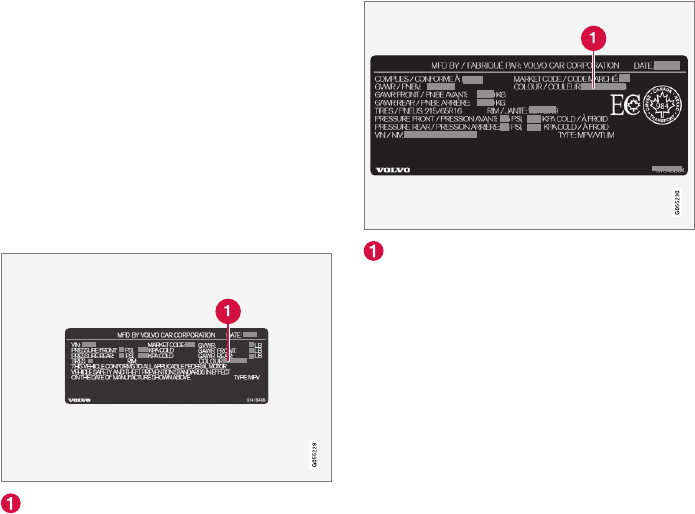
MAINTENANCE AND SERVICING
540
Corrosion protection
Your vehicle is constructed with effective protec-
tion against corrosion.
Inspection and maintenance
The corrosion protection does not normally
require maintenance but keeping the vehicle
clean helps prevent the onset of corrosion. The
use of strong alkaline or acidic cleaning fluids
should always be avoided on shiny body compo-
nents. Any stone chips in the paint should be
touched up as soon as possible.
Related information
•Paint damage (p. 540)
•Touching up paint damage (p. 541)
Paint damage
Paint damage requires immediate attention to
avoid rusting. Make it a habit to check the finish
regularly, for instance washing the vehicle.
Touch-up if necessary.
Paint repairs require special equipment and skill.
Contact your Volvo retailer for any extensive dam-
age.
Minor scratches can be repaired by using Volvo
touch-up paint.
Color code
Sample color code (1): US models
Sample color code (1): Canadian models
Make sure you have the right color. See also the
article "Label information" for the location of this
label.
Minor stone chips and scratches
Material:
•Primer – can
•Paint – touch-up pen
•Brush
•Masking tape
•Emery cloth
If the stone chip has not gone down to the bare
metal and an undamaged color coat remains, you
can add paint immediately after removing dirt.
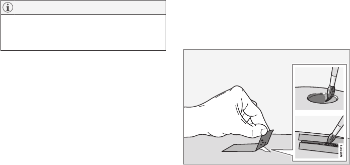
MAINTENANCE AND SERVICING
541
NOTE
When touching up the vehicle, it should be
clean and dry. The surface temperature
should be above 60 °F (15 °C).
Related information
•Label information (p. 544)
•Touching up paint damage (p. 541)
Touching up paint damage
Stone chips or other minor paint damage can be
repaired by the vehicle's owner.
Repairing stone chips
1. Place a strip of masking tape over the dam-
aged surface. Pull the tape off so that any
loose flakes of paint adhere to it.
2. Thoroughly mix the primer and apply it with a
small brush.
3. When the primer surface is dry, the paint can
be applied using a brush. Mix the paint thor-
oughly; apply several thin paint coats and let
dry after each application.
4. If there is a longer scratch, you may want to
protect surrounding paint by masking it off
5. After a few days, polish the touched-up
areas. Use a soft rag and a small amount of
polish.
Related information
•Paint damage (p. 540)
•Cleaning the exterior (p. 535)

MAINTENANCE AND SERVICING
542
Polishing and waxing
Normally, polishing is not required during the
first year after delivery, however, waxing may be
beneficial.
•Before applying polish or wax the vehicle
must be washed and dried. Tar spots can be
removed with kerosene or tar remover. Diffi-
cult spots may require a fine rubbing com-
pound.
•After polishing use liquid or paste wax.
•Several commercially available products con-
tain both polish and wax.
•Waxing alone does not substitute for polish-
ing a dull surface.
•A wide range of polymer-based waxes can
be purchased today. These waxes are easy to
use and produce a long-lasting, high-gloss
finish that protects the bodywork against oxi-
dation, road dirt and fading.
•Do not polish or wax your vehicle in direct
sunlight (the surface of the vehicle should
not be warmer than 113 °F (45 °C).
CAUTION
Volvo does not recommend the use of long-
life or durable paint protection coatings, some
of which may claim to prevent pitting, fading,
oxidation, etc. These coatings have not been
tested by Volvo for compatibility with your
vehicle's clear coat. Some of them may cause
the clear coat to soften, crack, or cloud. Dam-
age caused by application of paint protection
coatings may not be covered under your vehi-
cle's paint warranty.
Related information
•Paint damage (p. 540)
•Touching up paint damage (p. 541)

SPECIFICATIONS
SPECIFICATIONS
544
Label information
The labels in your vehicle provide information
such as the chassis number, paint code, tire
inflation pressure, etc.
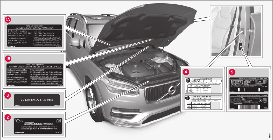
SPECIFICATIONS
}}
545
Location of labels

||
SPECIFICATIONS
546
List of labels
Vehicle Emission Control Information. (A)
US models, (B) Canadian models. Your Volvo
is designed to meet all applicable emission
standards, as evidenced by the certification
label on the underside of the hood. For fur-
ther information regarding these regulations,
please consult your Volvo retailer.
Engine oil. This label contains the recom-
mended engine oil specifications.
Vehicle Identification Number (VIN). The
VIN plate is located on the top left surface of
the dashboard. The Vehicle Identification
Number (VIN) should always be quoted in all
correspondence concerning your vehicle with
the retailer and when ordering parts.
Tire inflation pressures. This label indicates
the correct inflation pressures for the tires
that were on the vehicle when it left the fac-
tory.
Federal Motor Vehicle Safety Standards
(FMVSS) specifications (USA) and Minis-
try of Transport (CMVSS) standards
(Canada). Your Volvo is designed to meet all
applicable safety standards, as evidenced by
the certification label on the driver's side B-
pillar (the structural member at the side of
the vehicle, at the rear of the driver's door
opening). This label also includes codes for
paint color, etc. For further information regar-
ding these regulations, please consult your
Volvo retailer. U.S. models have the upper
decal; Canadian models have the lower one.
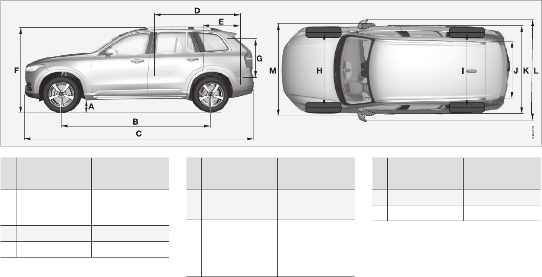
SPECIFICATIONS
}}
547
Dimensions
The following table lists your vehicle's most
important dimensions.
Dimension In.
(mm)
A Ground clearance
(curb weight + 2
people)A
9 (228)B
9.1 (232)C
B Wheelbase 117.5 (2984)
C Length 194.9 (4950)
Dimension In.
(mm)
D Load length, floor,
seatback downD
80.3 (2040)
49.6 (1260)E
E Load length, floor 48.0 (1220)B
21.8 ( 554)C
30.0/35.4
(761/898)F
Dimension In.
(mm)
F Height 69.9 (1776)
G Load height 32.1 (816)

||
SPECIFICATIONS
548
Dimension In.
(mm)
H Track, front (mod-
els without pneu-
matic suspension)
65.9 (1673)G
65.6 (1665)H
Track, front (mod-
els with pneumatic
suspension)
66.0 (1676)G
65.7 (1668)H
I Track, rear (models
without pneumatic
suspension)
65.8 (1675)G
66.1 (1667)H
Track, rear (models
with pneumatic
suspension)
66.1 (1679)G
65.8 (1671)H
J Load width, floor 46.9 (1192)
K Width 75.7 (1923)I
76.0 (1931)J
77.1 (1958)K
Dimension In.
(mm)
L Width incl. door
mirrors (folded out)
84.3 (2140)
M Width incl. door
mirrors (folded in)
79.1 (2008)
AVaries slightly depending on tire size, chassis options, etc.
B5-seat models.
C7-seat models*.
DNot 4-seat models
EFrom the second row of seats in 7-seat models*.
F4-seat models
GModels with 20, 21 and 22 in. wheels.
HModels with 18 and 19 in. wheels.
IChassis width.
JWidth on models with 18 and 19 in. wheels.
KWidth on models with 20, 21 and 22 in. wheels.

SPECIFICATIONS
}}
549
Weights
The following table lists important weight data
for your vehicle.
Category USA Canada
Gross vehicle weight
7-seat, 4-cyl. AWD (All Wheel Drive)
7-seat 4-cyl. FWD (Front Wheel Drive)
5-seat, 4-cyl. AWD
5-seat 4-cyl. FWD
4-seat, 4-cyl. AWD
6,060 lbs
6,005 lbs
6,005 lbs
6,005 lbs
-
2,750 kg
2,725 kg
2,725 kg
2,725 kg
2,725 kg
Capacity weight
7-seat, 4-cyl.
5-seat, 4-cyl.
4-seat, 4 cyl. AWD
1,210 lbs
1,100 lbs
-
550 kg
500 kg
500 kg
Permissible axle weights, front
7-seat, 4-cyl. AWD
7-seat, 4-cyl. FWD
5-seat, 4-cyl. AWD
5-seat, 4-cyl. FWD
4-seat, 4-cyl. AWD
2,885 lbs
2,865 lbs
2,865 lbs
2,865 lbs
2865 lbs
-
1,310 kg
1,300 kg
1,300 kg
1,300 kg
1,300 kg
1,300 kg

||
SPECIFICATIONS
550
Category USA Canada
Permissible axle weights, rear
7-seat, 4-cyl. AWD
7-seat, 4-cyl. FWD
5-seat, 4-cyl. AWD
5-seat, 4-cyl. FWD
4-seat, 4-cyl. AWD
3,280 lbs
3,280 lbs
3,280 lbs
3,280 lbs
-
1,490 kg
1,490 kg
1,490 kg
1,490 kg
1,470 kg
Curb weight
7-seat, 4-cyl.
5-seat, 4-cyl.
4-seat, 4 cyl.
4,370 - 4,680 lbs
4,290 - 4,530 lbs
-
1,980 - 2,130 kg
1,940 - 2,060 kg
2,130 - 2,140 kg
Max. roof load 220 lbs 100 kg

SPECIFICATIONS
551
Category USA Canada
Max. trailer weights Without brakes: 1,650 lbs
With brakes (AWD): 5,000 lbs
With brakes (FWD): 4,000 lbs
Without brakes: 750 kg
With brakes (AWD): 2,250 kg
With brakes (FWD): 1,800 kg
Max. tongue weight AWD: 500 lbs
FWD: 400 lbs
AWD: 225 kg
FWD: 180 kg
CAUTION
•When loading the vehicle, the maximum
gross vehicle weight and permissible axle
weights may not be exceeded.
•The maximum trailer weights listed are
only applicable for altitudes up to 3280 ft
(1,000 m) above sea level. With increas-
ing altitude the engine power and there-
fore the car's climbing ability are impaired
because of the reduced air density, so
the maximum trailer weight has to be
reduced accordingly. The weight of the
car and trailer must be reduced by 10%
for every further 3280 ft (1,000 m) (or
part thereof).
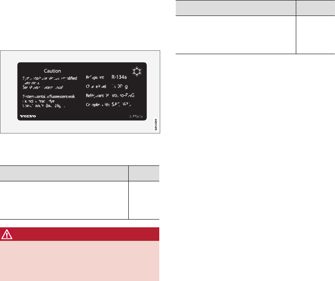
SPECIFICATIONS
* Option/accessory, for more information, see Introduction.
552
Air conditioning refrigerant
The air conditioning system in your car contains
a CFC-free refrigerant.
A/C decal
R134a decal
Refrigerant
Models with R134a
Weight Type
1.65 lbs (750 g)
2.2 lbs (1000 g) on models with A/C
for the third row of seats*
R134a
WARNING
The air conditioning system contains R134a
refrigerant under pressure. Service and
repairs may only be carried out by a trained
and qualified Volvo service technician.
Compressor oil
Volume Type
2.0 fl. oz. (60 ml)
2.7 fl. oz. (80 ml) on models with
A/C for the third row of seats*
PAG SP-
A2
Evaporator
The A/C system' s evaporator may never be
repaired or replaced with a previously used evap-
orator. A new evaporator must be certified and
marked according to SAE J2842.
Related information
•Climate system service (p. 503)
Brake fluid specification and volume
Brake fluid transfers braking force when the
brake pedal is depressed to the master cylinder
and to the slave cylinders on each wheel.
Topping up or replacing brake fluid should only
be done by a trained and qualified Volvo service
technician.
Specification: DOT 4 boiling point >536 °F
(>280 °C)
Related information
•Engine compartment overview (p. 529)
SPECIFICATIONS
553
Coolant specifications and volumes
Coolant volumes and specifications.
Engine: T6 AWD
Specification: Coolant with corrosion inhibitor
mixed with water (50/50 mix), see packaging.
Different types of coolant should not be mixed to
help avoid health risks.

SPECIFICATIONS
554
Engine specifications
The following table provides technical data for
the respective engines. Engine specifications for
Special Edition vehicles may vary.
Not all engines listed here are available in all
markets.
Specification T6 AWD
Engine designation B4204T27
Output (kW/rps) 235/95
Output (hp/rpm) 316/5700
Torque (Nm/rps) 400/37–90
Torque (ft. lbs./rpm) 295/2,200–5,400
No. of cylinders 4
Specification T6
Engine designation B4204T23
Output (kW/rps) 187/92
Output (hp/rpm) 250/5,500
Torque (Nm/rps) 350/25–80
Torque (ft. lbs./rpm) 258/1,500-4,800
No. of cylinders 4
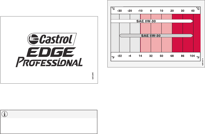
SPECIFICATIONS
556
Engine oil specifications and
volume
Full synthetic engine oil meeting the minimum
ACEA A5/B5 must be used. Lower quality oils
may not offer the same fuel economy, engine
performance, or engine protection.
Volvo recommends:
Refer to the warranty and Service Records infor-
mation booklet for information on oil change
intervals and oil type requirements.
NOTE
This vehicle comes from the factory with syn-
thetic oil.
Oil additives must not be used.
Oil viscosity
Incorrect viscosity oil can shorten engine life
under normal use. SAE 5W-30 will provide good
fuel economy and engine protection. See the vis-
cosity chart.
Viscosity chart
Extreme engine operation
Volvo oil VCC RBS0-2AE/SAE 0W20 is recom-
mended for extreme driving conditions.
Oil volume
The oil volume for the engine is:
6.2 US qts (5.9 liters).
Related information
•Checking and refilling engine oil (p. 531)
Fuel tank volume
The fuel tank's volume is shown below.
The fuel tank's refillable volume is approx. 18.8
US gallons (71 liters).
Related information
•Octane rating (p. 353)
•Opening/closing the fuel filler door (p. 354)

SPECIFICATIONS
557
Tire inflation pressure table
The following tire pressures are recommended
by Volvo for your vehicle. Refer to the tire infla-
tion placard for information specific to the tires
installed on your vehicle at the factory.
Tire sizes: XC90 Cold tire pressure for up to five or seven persons (depending on seating capacity)
Front
psi (kPa)
Rear
psi (kPa)
235/60 R18
235/55 R19
275/45 R20
275/40 R21
275/35 R22
38 (260) 38 (260)
Temporary spare tire
T125/80 R18
60 (420) 60 (420)
Related information
•Checking tire inflation pressure (p. 481)
SPECIFICATIONS
558
Transmission fluid specification and
volume
Under normal driving conditions the transmission
fluid does not need to be changed during its
service life. However, it may be necessary under
adverse driving conditions.
Transmission: TG-81SC
Specification: Transmission fluid AW-1

HOTSPOTS
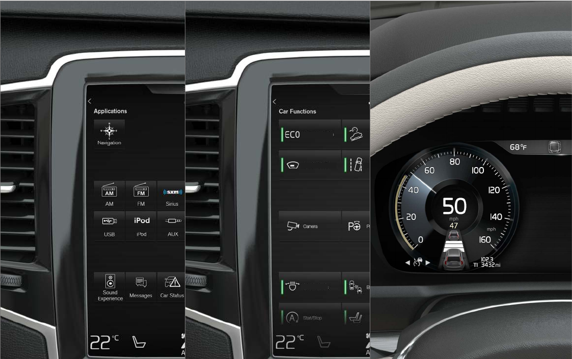
HOTSPOTS
560
Centerdisplay – App view
Apple
CarPlay
Centerdisplay – Car functions view
Driving mode
ECO
Hill Descent
Control
Head-up
display
Lane Keeping
Aid
Adjust passenger
seat
Wiper Service
Position
Park Assist
Active Bending
Lights
Instrument panel
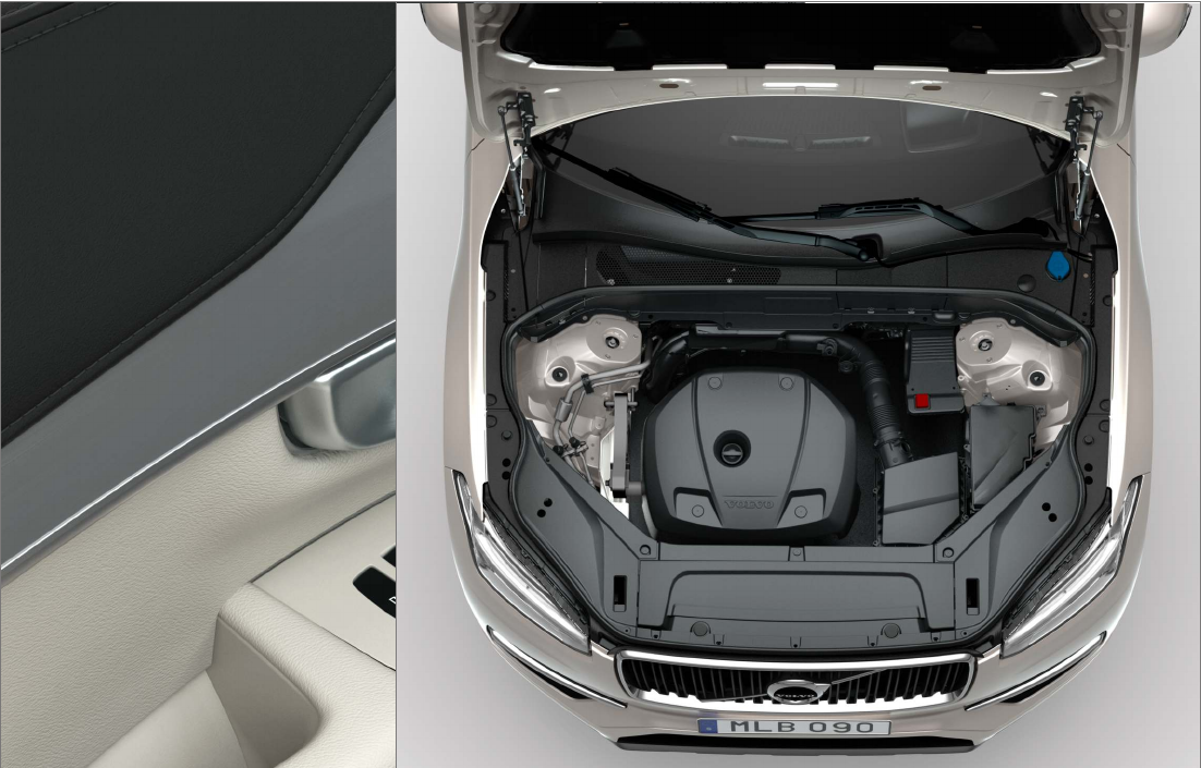
HOTSPOTS
}}
561
Driver's door panel Engine compartment Exterior
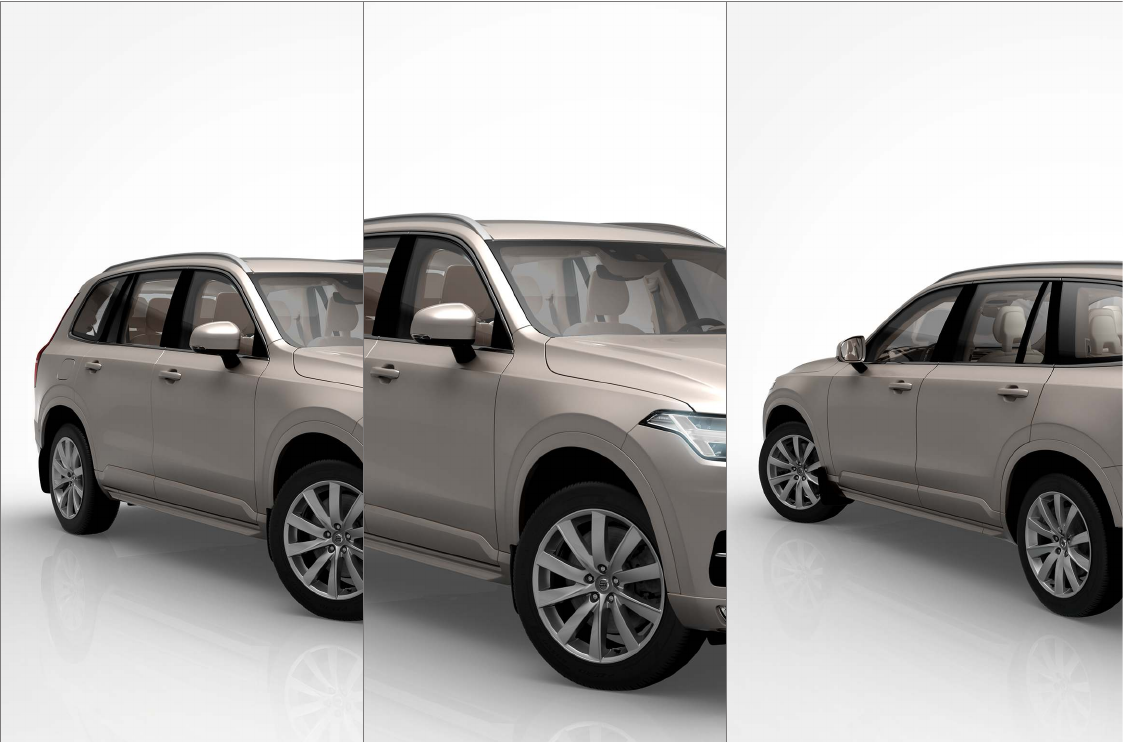
||
HOTSPOTS
562
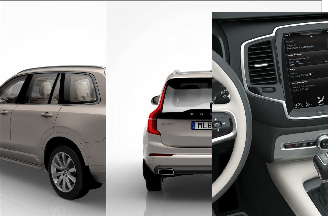
HOTSPOTS
563
Center display and tunnel consol
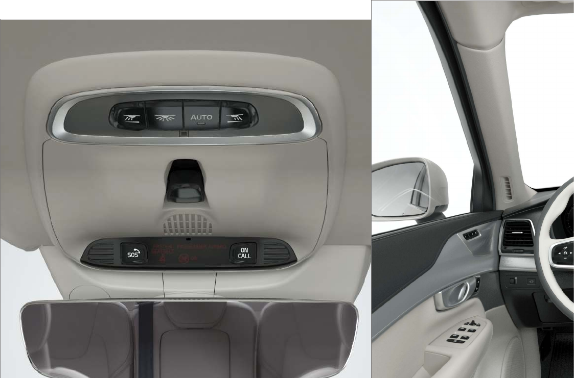
HOTSPOTS
564
Interior rearview mirror Interior
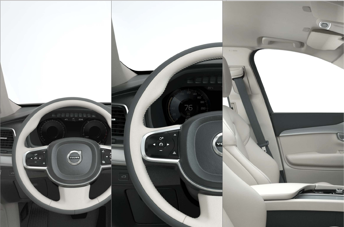
HOTSPOTS
}}
565
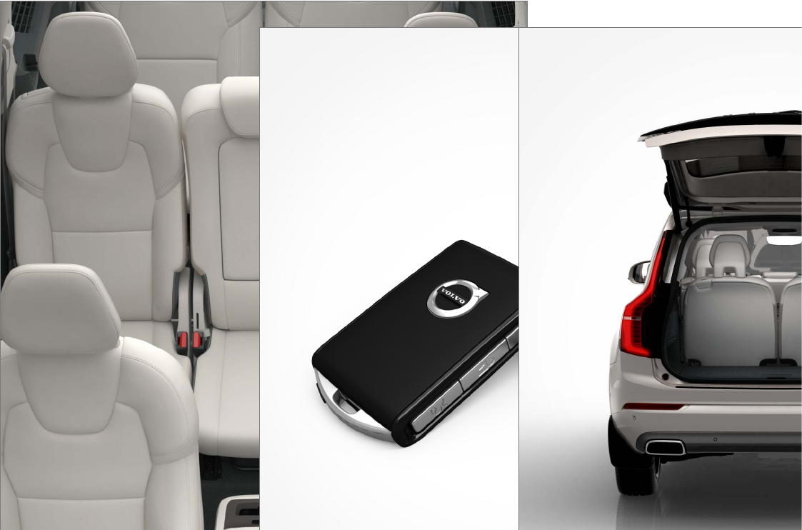
HOTSPOTS
566
Remote key Trunk

INDEX
567
A
A/C (air conditioning) 189
Accessory installation warning 21, 23
Active high beams 138
Active yaw control 313
Adaptive brake lights 340
Adaptive cruise control 256, 258, 259,
261, 262, 263, 272, 273, 274, 276
passing assistance 274
radar sensor 273, 274
Adaptive Cruise Control
fault tracing 275
Airbags
disconnecting the front passenger’s
side 80
front 84, 85
inflatable curtain 88
side impact 89
Air conditioning 189
Air distribution 193, 194
Air distribution table 195
Air filter 177
Air quality 175
Air quality sensor 175
Air vents 193
Alarm 216
automatically arming/disarming 218
Deactivating 218
All Wheel Drive 378
Ambient temperature sensor 112
Antennas
passive entry system 220
Anti-freeze 348
Apple CarPlay 400, 402
Applications (apps) 411
App menu 126
Approach lighting 142
Apps
changing settings 44, 111
Apps (applications) 413
Audio system 382
HD digital radio 386, 387, 388
SiriusXM® Satellite radio 389, 390, 391
sound settings 382, 406
voice control 116
Auto-hold brakes 338
Automatic locking retractor 66
Automatic transmission
Eco (driving function) 367
gear shift indicator 375
general description 373, 375
oil 558
shifting with steering wheel paddles 377
shiftlock override 374
Axle weight 479
B
Battery
avoiding drain 362
remote key, replacing 222
support battery 506
warning symbols 507
Battery – replacing 503
Blind Spot Information 320, 322
Bluetooth
connecting devices 395
Bluetooth®
hands-free 393
media 399, 406
microphone 396
streaming audio 406
Bluetooth cell phone connection 396
Booster cushion, integrated 77, 78, 79
Booster cushions 73
Brake assist system 339
Brake lights 140, 340
INDEX

INDEX
568
Brakes
auto-hold 338
Brake system
Brake pad inspection 337
fluid 552
general information 336, 338, 339
Bulbs 524
replacing 520
specifications 525
C
Camera
driver support systems 242
limitations 244
Camera, Park Assist 301, 303, 305, 306
Capacity weight 479, 549
Cargo area, steel grid 209
Cargo area cover 211
Cargo compartment
fuses 517
raising/lowering the level 205
Cargo net 207
Cargo space 198
Car wash 535
Catalytic converter 355
CD, USB, iPod, AUX, Bluetooth, Recents,
Library, Shuffle, Similar, Change device, Pri-
mary Audio Default Language, Subtitle, Pri-
mary Subtitle Default Language, Video,
DivX® VOD 403
CD player 403
Cell phone
hands-free 393
Pairing 393
Cell phone voice control 118
Center display
changing settings 30
cleaning 539
keyboard 31
navigating in 38
overview 28
screen in the center console 45
symbols in the status bar 43
Chains 481
Changing a wheel 483
Child restraints
recalls and registration 66
Child restraint systems 66
booster cushions 73
convertible seats 70
infant seats 68
ISOFIX/LATCH anchors 74
top tether anchors 76
Child safety 64
booster cushions 73
child restraint systems 66, 75
convertible seats 70
infant seats 68
Child safety locks 218
Child seats
lower attachment points 75
City safety 277, 283
City Safety
crossing traffic 281
detecting objects 280
limitations 283
rear collision warning 282
symbols and messages 287
troubleshooting 285
City Safety, On/Off 279
Cleaning
exterior 535
interior 537
Clean Zone Interior Package 176
Climate system 178
air distribution 193, 194, 195
air filter 177
air vents 193
auto mode 177
blower 181
center display controls 178

INDEX
569
Electronic Climate Control 178
introduction 174, 178
passenger compartment filter 176
rear controls 178, 180
recirculation 185
refrigerant 552
service 503
setting the temperature 183
voice commands 119
Clock 113
Cold weather driving 348
Collision warning system 278
Compass in rearview mirror 133
calibrate 134
Connected service booking 499
Convertible seats 70
Coolant 553
refilling 493
copyright 471
Corrosion protection 540
Courtesy lighting 143
Crash event data 25
Crash mode 83, 84
Cross Traffic Alert 323, 324, 325, 327
Cruise control 251, 252, 253, 254, 255
adaptive 256, 258, 259, 261, 262,
263, 272, 273, 274, 275, 276
Curb weight 479, 549
D
Daytime running lights 135, 137
Defroster
rear window and mirrors 186
Destination
save 450
Detachable key blade 227, 238
Digital owner's manual 51, 52
Dimensions 547
Disconnecting the front passenger’s airbag 80
Display
head-up 113
Distance Alert 319, 320
Dome lighting 143
Door mirrors 100
defroster 186
Drive mode 365
Driver's seat
easy access 165
Driver alert 317, 318
Lane Departure Warning 328, 332
Lane Keeping Aid 328, 332
Driver distraction warning 21, 23
Driver support systems 242
Driving economically 345
Driving in cold weather 348
Driving through water 346
E
Eco (driving function) 367
Eco coast 367
Economical driving 345
Electrical sockets 202
Electric parking brake 341, 342, 344
Electronic Climate Control (ECC) 178
Electronic stability control 313
Emergency brake
parking brake 341, 342, 344
Emergency brake lights 340
Emergency locking retractor 66
Emergency starting 355
Emergency towing 349
Emission inspection readiness 496
Engine
overheating 347
Start/Stop 370, 372

INDEX
570
starting 362
turning off 364
Engine compartment
fuses 509
Engine compartment overview 529
Engine oil 556
checking 530, 531
Engine specifications 554
Entering a destination
POI 448
Entering destination
free-text search 444
recent options 446
tapping the map 444
using an address 449
Enterining destination 443
Environment 15
Eyelet
towing 348
Eyelets for anchoring loads 210
F
Federal Clean Air Act 496
Floor mats
placing correctly 362
Fluid specifications 552, 553, 558
Fog lights
front 140
rear 141
Front airbags 84, 85
disconnecting passenger’s side airbag 80
Front fog lights 140
Front park assist 296, 298, 300
Front seats
heated 190
multifunctional 161, 162
power 159, 160, 165
Front seats, manual adjustment 158
Fuel filler door, opening 354
Fuel requirements 352, 353
Function view 36
Fuses 508
cargo compartment 517
engine compartment 509
passenger compartment 513
Fuses, replacing 508, 509, 513, 517
G
Garage door opener
HomeLink® Wireless Control Sys-
tem 95, 96
Gasoline requirements 352, 353
Glossary of tire terminology 477
Glove compartment 199
Grocery bag holder 207
Gross vehicle weight 479
Gross vehicle weight (GVW) 549
H
Hand brake (parking brake) 341, 342, 344
Hazard warning flashers 141
HD digital radio 386, 387, 388
Headlights
Active Bending Lights 139
active high beams 138
daytime running lights 135, 137
high/low beams 137
high beam flash 137
removing cover 522
Headlight washers 154
Head restraint - center, rear 166

INDEX
571
Head restraints, rear seat 166
Head-up display 113
Heated front seats 190
Heated oxygen sensors 355
Heated steering wheel 188
High beam bulb, replacing 523
High beams 137
active 138
Hill Descent Control 340
Hill Start Assist (HSA) 341
Hoisting the vehicle 526
HomeLink® Wireless Control System 95, 96
Home safe lighting 143
Hood, opening/closing 528
Horn, Keypad, Paddles, Signal 155
I
ID, Volvo 26
Ignition modes 360
Immobilizer (start inhibitor) 221
Indicator lights 131
Infant seats 68
Inflatable Curtain 88
Inflation pressure 481
Inflation pressure table 557
Information lights 131
Infotainment 420
Infotainment (Infotainment system) 382
Infotainment system 386, 387, 388
CD player 403
cell phone 393
general sound settings 382
Gracenote 407
introduction 382
media player 399, 403
media player sound settings 406
media search 405
radio 383
searching for radio stations 384
sound settings 382, 406
type approval 416
video 408
voice control 116
Inspection readiness 496
Instrument lighting 136
Instrument overview 98
Intellisafe 16
Interior Air Quality System 176
Interior lighting 143
Internet connection 409
applications (apps) 411
bluetooth settings 412
booking service 499
establishing a connection 410
troubleshooting 414
ISOFIX/LATCH anchors 74
Itinerary
Guidance points 452
J
Jack 484
location of 484, 486
Jump starting 351, 355
K
Key
remote 225
Key blade 227, 238

INDEX
572
L
Labels
list of 546
location of 545
Laminated panoramic roof 102
Lane Departure Warning
settings 330
Lane Departure Warning (LDW) 328, 332
Lane Keeping Aid 328, 330, 332
settings 330
LATCH anchors 74
Leather care 537
Licence
copyright 469
Lighting panel 135
Load anchoring eyelets 210
Loading the vehicle 198, 205, 479
Locking 232, 233
Locks and alarm 216
Low beam bulb, replacing 522
Low beams 136, 137
Low Speed Control 378
M
Maintenance 496
hoisting the vehicle 526
performed by the owner 496
Malfunction indicator light 121
Manual front seat adjustment 158
Map
buttons and information 436
Information cards 454
Map updates
computer with USB flash drive 467
MapCare 465
Remote 466
Media player 399
compatible file formats 408
Media player (infotainment system) 403
Menus
instrument panel 146, 148, 150, 151
Mirrors
defroster 186
power door 100
retractable 100
Mirrors, rearview mirror 106
Modem 415
Motor oil
checking 530, 531
MP3 files 408
Multifunctional front seats 161, 162
MY CAR 107, 108
N
Navigation
enhanced traffic information 456
instrument panel 457
Quick guidance 441
Sensus Navigation 440
Navigation displays
controls 441
Navigation system
features 437
voice commands 120, 441
Net
cargo 207
O
Occupant safety 56
Occupant weight sensor 80
Octane recommendations 353
Odometer 92

INDEX
573
Oil
checking 530, 531
Oil quality 556
On-board diagnostics 496
On-board Diagnostic socket 21
On Call Roadside Assistance 14
Opening the hood 528
Options 21
Outside temperature sensor 112
Overhead courtesy lighting 143
Overheating, engine 347
Owner's information
mobile applications 20
Owner's manual 16
Ownership, changing 112
Oxygen sensors, heated 355
P
Paint, touching up 540, 541
Park assist 296, 298, 300
Park Assist Camera 301, 303, 305, 306
settings 301, 305
Park Assist Pilot 306, 308, 310, 312
Parking brake
electric, applying/releasing 342, 344
Parking light bulb, replacing 524
Passenger compartment
fuses 513
Passive Entry system
location of antennas 220
Permissible axle weight 549
Phone
receiving calls 396
text messages 397, 398
Pilot Assist 263, 266, 267, 268, 269, 270
Polishing 542
Power front seat
memory function 160
Power mirrors 100
defroster 186
Power steering
adjustable 313
Power tailgate 236
Power windows 104, 105
Pregnancy, using seat belts during 58
PROPOSITION 65 WARNING 355
R
Radar
driver support systems 247
Radar sensor
limitations 248, 273
Radio
RBDS 384
settings 383
SiriusXM® Satellite radio 389, 390, 391
Radio functions
HD digital radio 386, 387, 388
Rain sensor 153
Rear Collision Warning 282
Rear fog lights 141
Rear park assist 296, 298, 300
Rear seat head restraints 166
Rear seats 165
accessing the third row 170
adjusting backrest tilt 167
center head restraint 166
folding 168, 170, 171
moving forward/rearward 170
Rearview mirror
compass 133, 134
Rear window defroster 186
Recalls 58

INDEX
574
Recalls, child restraints 66
Recirculation (climate system) 185
Refrigerant (A/C system) 552
Refueling 352, 353
fuel filler door 354
Registering child restraints 66
Remote key 225, 230
immobilizer 221
range 225
replacing the battery 222
Remote updates 499
Replacing bulbs 520
Replacing fuses 508, 509, 513, 517
Reporting safety defects 57
Roadside Assistance 14
Road sign information (RSI) 294, 295, 296
Rollover Protection System (ROPS) 317
Roll Stability Control (RSC) 317
Rout
Detour 455
S
Safety, occupant 56
Safety defects, reporting 57
Safety locks, child 218
Safety mode 83
Seat
adjusting the passenger's seat from the
driver's seat 160
Seat belt
reminder 63
Seat belts
Automatic locking retractor/Emergency
locking retractor 66
buckling 61
pretensioners 60, 61
reminder 63
securing child restraint systems 68, 70, 73
unbuckling 61
use during pregnancy 58
using 60
Seats
rear 165
Sensus 17
navigation 436
Service
connected service booking 499
Settings
guidance 464
Map 459
Route 461
Sensus Navigation 458
System 464
Traffic information 463
Settings view
categories 108
resetting 111
system settings 110
Shiftlock
override 374
Side door mirrors 100
Side impact airbags 89
SiriusXM® Satellite radio
traffic information 389, 390, 391
Snow chains 481
Snow tires 481
Sound settings
media 406
ringtones 398
Sound settings, audio system 382, 406
Specifications
bulbs 525
Speed camera alert 295
Speed limiter 288, 289, 294
automatic 290, 292
deactivating/reactivating 293
starting/activating 289
Spin control 313

INDEX
575
Stability system 313
sport mode 314
Start/Stop (engine function) 370, 372
Start and lock system
type designations 220
Starting and driving 336
Starting the engine 362
Starting the vehicle
after a crash (crash mode) 83, 84
Start inhibitor (immobilizer) 221
Steel grid in cargo area 209
Steering wheel 155
adjusting 157
heated 188
horn 155
keypad 155
Steering wheel paddles 155
Stone chips, touching up 540, 541
Storage compartments 198
Studded tires 481
Sunroof
laminated panoramic roof 102
Sun shade 104, 107
Sun visor 201
Suspension 379
System updates 498
T
Tailgate
locking/unlocking 235
operating with the foot movement sen-
sor 228
power operated 236
wiper/washer 155
Tailgate wipers 533
Technician certification 53
Temperature
perceived 174
Temperature sensor
ambient 112
Temporary spare tire 484
Tethering
wi-fi sharing 414
Three-way catalytic converter 355
Tire inflation pressure 557
Tire Pressure Monitoring System 488, 491
calibrating 492
type approval 492
Tire Pressure Monitoring System (TPMS) 492
Tires 474
changing 483
changing from summer to winter 478
glossary of terms 477
improving economy 474
inflation pressure 481
inflation pressure table 557
installing (mounting) a wheel on the
vehicle 487
rotation 475
snow 481
spare 484
specifications 475
storing 475
studded 481
tire pressure monitoring system 488, 491
tools in the cargo compartment 483
tread wear indicator 479
uniform tire quality grading 480
wheel bolts 485
Top tether anchors (child restraint sys-
tems) 76
Touching up paint 540, 541
Towing a trailer 357, 359
trailer hitch 358
Towing eyelet 348
Towing the vehicle 349
Traction control 313
Trailer towing 357, 359
trailer hitch 358

INDEX
576
Transmission
gear shift indicator 375
general description 373, 375
Hill Start Assist 341
oil 558
shifting with steering wheel paddles 377
shiftlock override 374
Tread wear indicator 479
Trip computer 92, 93, 94
reset 93
Trip odometers 92
Trips, long distance 345
Trip statistics 94
Troubleshooting
Sensus Navigation 471
Turn signals 145
changing bulbs 524
U
Uniform Tire Quality Grading 480
Unlocking the tailgate 235
Unlocking the vehicle 232, 233
USB/AUX connection 399, 406
V
Vehicle Event Data 25
Vehicle information 14
Vehicle loading 205, 479
Vehicle maintenance 496
performed by the owner 496
Vehicle status 499
Vehicle weights 549
Voice control
cell phones 118
giving commands 117
introduction 116
multimedia devices 118
radio 118
settings 121
Volvo and the environment 15
Volvo ID 26
Volvo maintenance 496
Volvo On Call
areas of availability 430
convenience services 424
personal information 428
PIN code 426
remote door unlock 434
safety services 432, 433
security services 433
using 422
Volvo On Call Roadside Assistance 14
Volvo On Call with Sensus Connect 422, 423
Volvo programs 14
W
Warning flashers, hazard 141
Warning lights 131
Warning system, collision 278
Warranties 496
Washer fluid 534
Washers
headlight 154
windshield 152
Water, driving through 346
Waxing 542
Weights
trailer 357
Wheels
changing 483, 486
storing 475
Whiplash Protection System 59
Wi-Fi 414, 415
INDEX
577
Windows
laminated glass 53
power 104, 105
sun shade 104
Windshield
rain sensor 153
washers 154
wipers/washers 152
Windshield washer fluid reservoir 534
Windshield wiper blades 533
Windshield wipers
service position 532
Wiper blades
replacing 532, 533
replacing tailgate wiper 533
WMA files 408
Workshop
Wi-Fi connection 502
INDEX
578

TP 20397 (English - USA & Canada), AT 1546, MY16, Printed in Sweden, Göteborg 2015, Copyright © 2000-2015 Volvo Car Corporation
