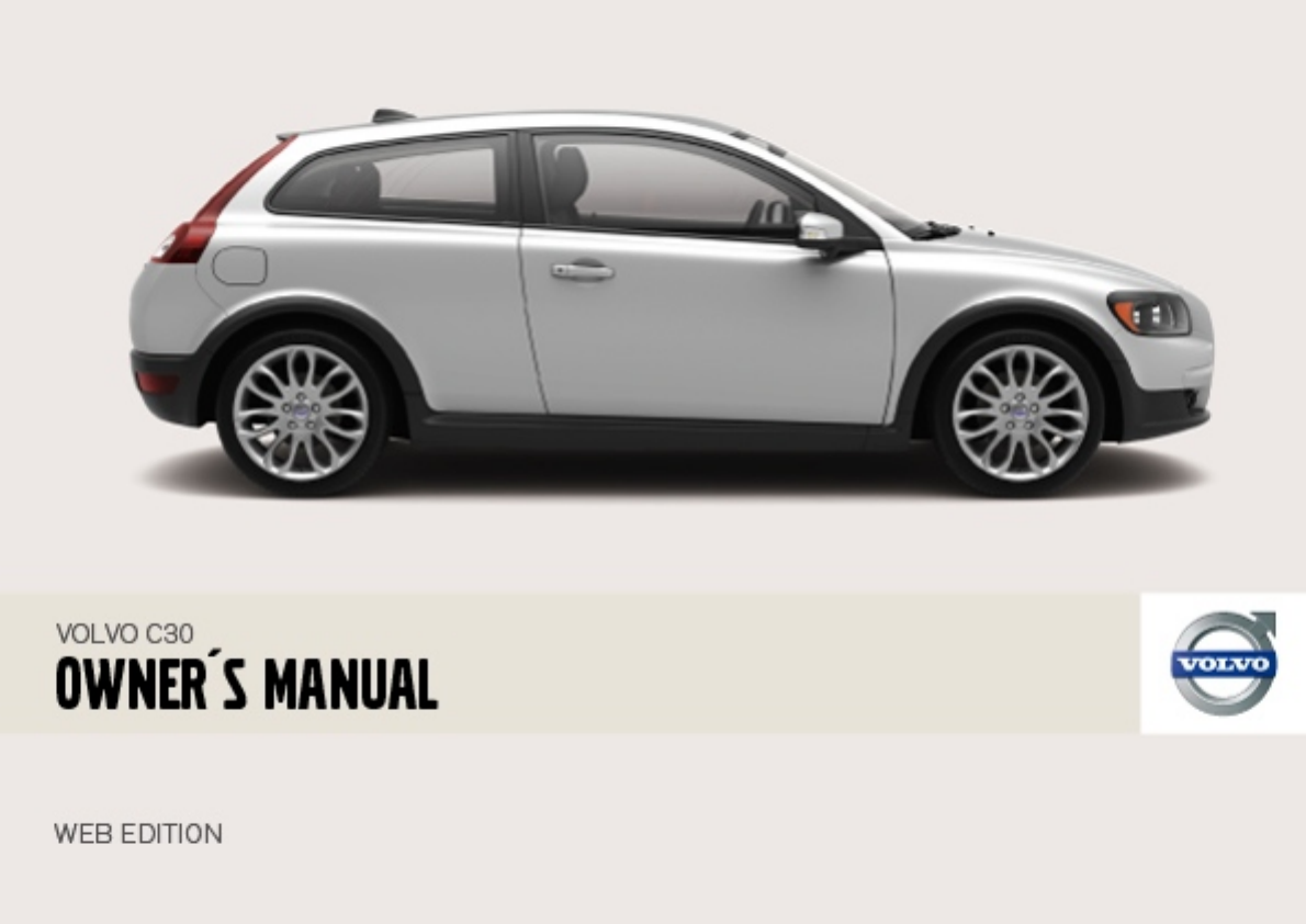
Volvo C30 Users Manual W637
C30 to the manual 8f7887c7-5564-4f05-a252-04f19945aaf0
2015-01-26
: Volvo Volvo-C30-Users-Manual-233578 volvo-c30-users-manual-233578 volvo pdf
Open the PDF directly: View PDF ![]() .
.
Page Count: 247 [warning: Documents this large are best viewed by clicking the View PDF Link!]
- Owner’s Manual
- Volvo Cars’ environmental philosophy
- Efficient emission control
- Clean air in the passenger compartment
- Reducing environmental impact
- Always use a seatbelt
- Seatbelt reminder
- Seatbelts and pregnancy
- Seatbelt guide
- Warning symbol on the combined instrument panel
- Airbag (SRS) on the driver’s side
- Passenger airbag (SRS)
- SRS system
- PACOS (option)
- Switch position
- Side airbags - SIPS bags
- SIPS bags
- Properties
- Protection against whiplash injury - WHIPS
- WHIPS system and child seats/ booster cushions
- Do not obstruct the WHIPS system
- Driving after a collision
- Children should sit comfortably and safely
- Child seats and airbags
- Placement of children in the car
- Fitting a child seat
- ISOFIX fixture system for child seats (option)
- Driver’s door control panel
- Functionality check, symbols
- Symbols in the centre of the instrument panel
- Indicator symbols - left-hand side
- Indicator symbols - right-hand side
- Reminder - doors not closed
- Messages
- 12 V electrical socket
- Cigarette lighter (option)
- Headlamp levelling
- Stalk switch positions
- Trip computer (option)
- Windscreen wipers
- Rain sensor (option)
- Activating
- Increasing or decreasing speed
- Temporary disengagement
- Steering wheel adjustment
- Hazard warning flashers
- Parking brake (handbrake)
- Electrical socket in rear seat
- Operating
- Passenger seat
- Interior rearview mirror
- Interior rearview mirror with compass (option on certain markets)
- Door mirrors
- Open positions
- Closing with remote control or lock button
- Possible settings
- Air conditioning
- Air vents in the dashboard
- ECC (option)
- Control panel
- Control panel
- General information about heaters
- Activating the heater
- Immediate stop of heater
- Seating position
- Power seat (option)
- Reading lamps and interior lighting
- Automatic lighting
- Vanity mirror
- Storage spaces
- Glovebox
- Lowering the rear seat backrest
- Armrest in the rear seat
- Bottle holder (option)
- Soft cargo cover (option)
- Hard cargo cover (option)
- Safety net (option)
- Load retaining eyelets
- Remote control
- Remote control functions
- Key blade
- Weak remote control battery
- Replacing the remote control battery
- Keyless lock and ignition system
- Unlocking
- Locking
- Locking/unlocking the car from outside
- Tailgate
- Locking/unlocking from inside
- Locking the glovebox
- Deadlocks
- Alarm system
- Alarm lamp on instrument panel
- Testing the alarm system
- Economical driving
- Do not overload the battery
- Opening the fuel filler flap
- Before starting the engine
- Starting the engine
- Diesel particle filter (DPF)
- Ignition switch and steering lock
- General
- Starting the car
- Starting with the remote control
- Gear positions, five-speed
- Reverse gear inhibitor, five-speed
- Gear positions, six-speed (petrol)
- Reverse gear inhibitor, six-speed (petrol)
- Gear positions, six-speed (diesel)
- Reverse gear inhibitor, six-speed (diesel)
- Cold start
- Safety systems
- Disengaging shiftlock
- Mechanical gear selector inhibitor
- Automatic gear positions
- Manual positions
- W - Winter
- Brake servo
- General
- Reduced operation
- General
- Cleaning the sensors
- General
- Never tow the car to bump start it
- Recovery
- Starting with a donor battery
- General
- Automatic gearbox, driving with a trailer
- Diesel 1.6D engine with manual gearbox, driving with a trailer
- Towbars
- Trailer cable
- Specifications
- Fitting the towball
- Removing the towball
- General
- Using load carriers
- Correct light pattern for left or right- hand traffic
- Driving characteristics and tyres
- Speed ratings
- New tyres
- More even wear and maintenance
- Spare wheel Temporary Spare
- Summer and winter wheels
- Recommended tyre pressure
- Tyre pressure table
- Warning triangle
- Removing wheels
- Fitting the wheel
- General
- Inflating tyres
- Sealing punctured tyres
- Replacing the sealing fluid canister
- Washing the car
- Polishing and waxing
- Cleaning door mirrors and front side windows with water-repellent surface (option)
- Cleaning the interior
- Paintwork
- Stone chips and scratches
- Inspection and maintenance
- Volvo service programme
- Before starting work on the car
- Check regularly
- Opening the bonnet
- Fuel system
- Engine compartment decal for oil grade
- Checking the engine oil and oil filter
- Checking the oil
- Washer fluid, topping up
- Checking and topping up the coolant
- Checking and topping up the brake and clutch fluid
- Checking and topping up the power steering fluid
- Replacing the wiper blades
- Replacing the wiper blades, rear window
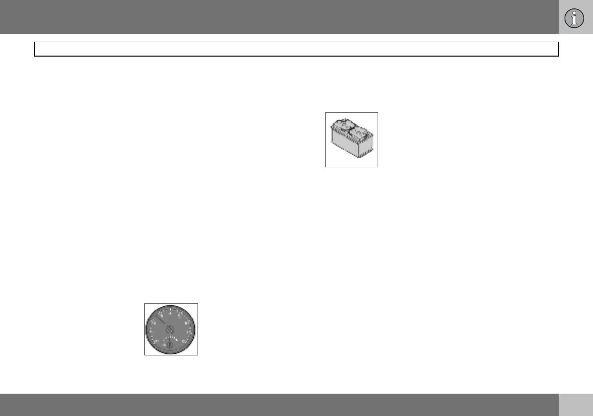
- Battery care
- Symbols on the battery
- Replacing the battery
- General
- Replacing front bulbs
- Dipped beam
- Main beam
- Position/parking lamps
- Direction indicators
- Side marker lamps
- Fog lamps
- Removing the bulb holder
- Location of the bulbs in the rear lamp cluster
- Number plate lighting
- Reflector
- Courtesy lighting
- Cargo area
- Vanity mirror lighting
- General
- Relay/fuse box in the engine compartment
- Relay/fuse box in the passenger compartment
- Dolby Surround Pro Logic II
- Audio controls
- Audio source selection
- Radio controls
- Display of programme type
- CD function controls
- Phone system components
- SIM card
- Phone controls
- Steering wheel keypad
- On/Off
- Volume
- Handling numbers
- Specifications
- Overview
- Description of menu options
- Dimensions
- Weights
- Adverse driving conditions
- Viscosity chart
- Oil decal
- Oil decal
- Oil decal
- Consumption, emissions and volume
- Fuel consumption and emissions of carbon dioxide
- General
- General
- Bulbs
- Type approval, remote control system
DEAR VOLVO OWNER
THANK YOU FOR CHOOSING VOLVO
We hope you will enjoy many years of driving pleasure in your
Volvo. The car has been designed for the safety and comfort
of you and your passengers. Volvo is one of the safest cars in
the world. Your Volvo has also been designed to satisfy all cur-
rent safety and environmental requirements.
In order to increase your enjoyment of the car, we recommend
that you familiarise yourself with the equipment, instructions
and maintenance information contained in this Owner’s
Manual.
Contents
2
00 Introduction
Introduction ........................................6
Volvo Car Corporation and the
environment ........................................7
01 Safety
Seatbelts .......................................... 12
Airbag system .................................. 15
Airbags (SRS) ................................... 16
Activating/deactivating the
airbag (SRS) ..................................... 19
Side airbags (SIPS bags) .................. 21
Inflatable Curtain (IC) ....................... 23
WHIPS .............................................. 24
When the systems deploy ................ 26
Crash mode ...................................... 27
Child safety ...................................... 28
02 Instruments and controls
Overview, left-hand drive car ............34
Overview, right-hand drive car ..........36
Driver’s door control panel ...............38
Combined instrument panel .............39
Indicator and warning symbols .........40
Information display ...........................43
Electrical socket and switch, centre
console .............................................45
Lighting panel ...................................46
Left-hand stalk switch ......................48
Right-hand stalk switch ....................50
Cruise control (option) ......................52
Steering wheel keypad (option) ........54
Steering wheel adjustment, hazard
warning flashers ................................55
Parking brake, electrical socket ........56
Power windows .................................57
Rearview and door mirrors ...............59
Power sunroof (option) ......................62
Personal preferences ........................64
Contents
3
03 Climate control
General information on climate
control .............................................. 68
Manual climate control, A/C ............. 70
Electronic climate control,
ECC (option) ..................................... 72
Air distribution .................................. 75
Fuel-driven heater (option) ............... 76
04 Interior
Front seats ........................................80
Interior lighting ..................................82
Storage spaces in the passenger
compartment ....................................84
Rear seat ...........................................86
Cargo area ........................................87
05 Locks and alarm
Remote control with key blade .........94
Keyless drive (option) .......................98
Locking and unlocking ...................100
Alarm (option) ................................. 103
Contents
4
06 Starting and driving
General ........................................... 108
Refuelling ........................................ 110
Starting the engine ..........................111
Keyless drive (option) ..................... 113
Manual gearbox .............................. 114
Automatic gearbox ........................ 116
Brake system .................................. 119
Stability and traction control
system ............................................ 121
Parking assistance (option) ............. 123
Blind Spot Information System BLIS
(option) ............................................ 125
Towing and recovery ....................... 128
Jump starting ................................. 130
Driving with a trailer ........................ 131
Towing bracket ............................... 133
Detachable towbar ......................... 135
Loading ........................................... 140
Adjusting headlamp pattern ........... 141
07 Wheels and tyres
General ........................................... 144
Tyre pressure .................................. 148
Warning triangle and spare wheel .. 150
Changing wheels ............................ 151
Emergency puncture repair ............ 153
08 Car care
Cleaning ..........................................162
Touching up paintwork ....................165
Rustproofing ...................................166
Contents
5
09 Maintenance and service
Volvo service .................................. 170
Self-maintenance ........................... 171
Bonnet and engine compartment .. 172
Diesel .............................................. 173
Oils and fluids .................................174
Wiper blades .................................. 178
Battery ............................................ 179
Replacing bulbs ............................. 181
Fuses .............................................. 187
10 Infotainment system
General ...........................................196
Audio functions ...............................197
Radio functions ...............................199
CD functions ...................................203
Menu structure – audio system ......205
Phone functions (option) .................206
Menu structure – phone ..................213
11 Specifications
Type designation .............................220
Dimensions and weights ................221
Engine specifications .....................224
Engine oil ........................................226
Fluids and lubricants ......................230
Fuel .................................................232
Catalytic converter .........................234
Electrical system ............................235
Introduction
6
Introduction
Owner’s Manual
A good way of getting to know your new car
is to read the Owner’s Manual, ideally before
your first journey. This will give you the op-
portunity to familiarise yourself with new
functions, to see how best to handle the car
in different situations, and to make the best
use of all the car’s features. Please pay at-
tention to the safety instructions contained in
the manual.
The equipment described in the owner’s
manual is not present in all models. In addi-
tion to standard equipment, this manual also
describes options (factory fitted equipment)
and certain accessories (extra equipment).
The specifications, design features and illus-
trations in this owner’s manual are not bind-
ing. We reserve the right to make modifica-
tions without prior notice.
© Volvo Car Corporation
WARNING
"Warning" texts indicate where there is a
risk of personal injury in the event of the in-
structions not being followed.
IMPORTANT
"Important" texts indicate a risk of damage
to the car in the event of the instructions not
being followed.
NOTE
Volvo cars are adapted for the varying re-
quirements of different markets, as well as
for national or local legal requirements and
regulations.
Introduction
7
Volvo Car Corporation and the environment
Volvo Cars’ environmental philosophy
Environmental care, safety and quality are
the three core values which influence all op-
erations of the Volvo Car Corporation. We
also believe that our customers share our
consideration for the environment.
Your Volvo complies with strict international
environmental standards and is also manu-
factured in one of the cleanest and most re-
source-efficient plants in the world. Volvo
Car Corporation has global certification to
the ISO 14001 environmental standard. This
standard supports the work within the area of
the environment.
EPI (Environmental Product Information) is
supplied for all Volvo models. There you can
see how the car’s lifecycle affects the envi-
ronment.
Read more at www.volvocars.com/EPI.
Fuel consumption
Volvo cars have competitive fuel consump-
tion in each of their respective classes. Low-
er fuel consumption generally results in lower
emission of the greenhouse gas, carbon
dioxide.
It is possible for the driver to influence fuel
consumption. For more information read un-
der the heading, Reducing environmental im-
pact, on page 9.

Introduction
8
Volvo Car Corporation and the environment
Efficient emission control
Your Volvo is manufactured following the
concept Clean inside and out – a concept
that encompasses a clean interior environ-
ment as well as highly efficient emission con-
trol. In many cases the exhaust emissions are
well below the applicable standards.
In addition there is a special radiator coating,
PremAir®1, which can convert hazardous
ground-level ozone into pure oxygen when
the ozone passes the radiator. The higher the
ozone content of the air the more ozone is
converted.
Clean air in the passenger
compartment
A passenger compartment filter prevents
dust and pollen from entering the passenger
compartment via the air intake.
A sophisticated air quality system, IAQS2 (In-
terior Air Quality System) ensures that the in-
coming air is cleaner than the air in the traffic
outside.
The system consists of an electronic sensor
and a carbon filter. The incoming air is moni-
tored continuously and if there is an increase
in the level of certain unhealthy gases such
as carbon monoxide then the air intake is
closed. Such a situation may arise in heavy
traffic, queues and tunnels for example.
The entry of nitrous oxides, ground-level
ozone and hydrocarbons is prevented by the
carbon filter.
Textile standard
The interior of a Volvo is designed to be
pleasant and comfortable, even for people
with contact allergies and for asthma suffer-
ers. All of our upholstery and interior textiles
are tested with respect to certain unhealthy
substances and allergens as well as emis-
sions. This means that all textiles fulfil the re-
quirements in the Öko-Tex 1003 standard, a
major advance towards a healthier passen-
ger compartment environment.
Öko-Tex certification covers seatbelts, car-
pets, thread and fabrics for example. The
leather in the upholstery undergoes chromi-
um-free tanning with natural plant substanc-
es and fulfils the certification requirements.
Volvo workshops and the environment
Regular maintenance creates the conditions
for long service life for the car and low fuel
consumption, and this way you contribute to
a cleaner environment. When Volvo’s work-
shops are entrusted with the repair and
maintenance of the car, it becomes part of
our system. We make clear demands regard-
ing the way in which our workshops are de-
signed in order to prevent spills and dis-
charges into the environment. Our workshop
staff have the knowledge and the tools re-
quired to guarantee good environmental
care.
1Option for 5-cylinder engines. (Certain mar-
kets)
PremAir® is a registered trademark of
Engelhard Corporation. 2Option 3More information on www.oekotex.com
Introduction
9
Reducing environmental impact
You can help reduce environmental impact,
for example, by driving economically, by pur-
chasing eco-labelled car care products and
by servicing and maintaining the car accord-
ing to the instructions in the owner’s manual.
The following hints will help you to do your bit
for the environment:
• Decrease fuel consumption by choosing
ECO tyre pressure, see page 148.
• A roof load and ski box increase air resist-
ance, leading to significantly higher fuel
consumption. Remove them immediately
after use.
• Remove unnecessary items from the car.
The greater the load the higher the fuel
consumption.
• If the car is equipped with an engine block
heater use it for a few hours before start-
ing from cold. This reduces fuel consump-
tion and exhaust emissions.
• Drive gently and avoid braking too hard.
• Drive in the highest gear
possible. Low engine
speeds result in lower fuel
consumption.
• Ease back on the acceler-
ator on downhill gradi-
ents.
• Use engine braking to slow down.
• Avoid idling. Take consideration of local
regulations. Switch off the engine in traffic
queues.
• Always dispose of envi-
ronmentally hazardous
waste, such as batteries
and oils, in an environ-
mentally safe manner. If
uncertain about disposal,
consult an authorised
Volvo workshop for advice.
• Service your car regularly.
These hints will help you reduce fuel con-
sumption without increasing travel time or
lessening the enjoyment of driving. Apart
from being kind to your car, you’ll be saving
money - and the Earth’s resources.

10
Seatbelts .................................................................................................. 12
Airbag system .......................................................................................... 15
Airbags (SRS) ...........................................................................................16
Activating/deactivating the airbag (SRS) .................................................. 19
Side airbags (SIPS bags) .........................................................................21
Inflatable Curtain (IC) ...............................................................................23
WHIPS ......................................................................................................24
When the systems deploy ........................................................................26
Crash mode ..............................................................................................27
Child safety ..............................................................................................28
01
SAFETY
01 Safety
12
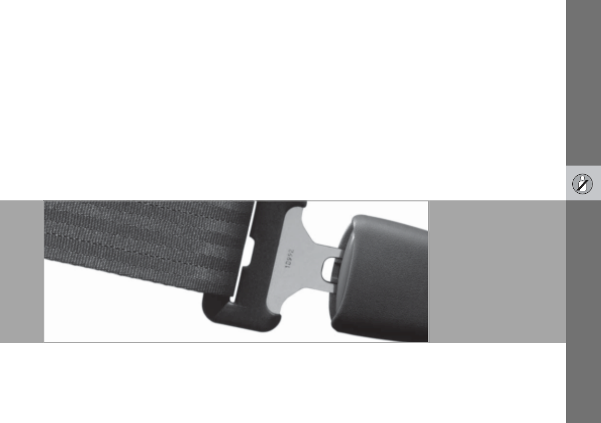
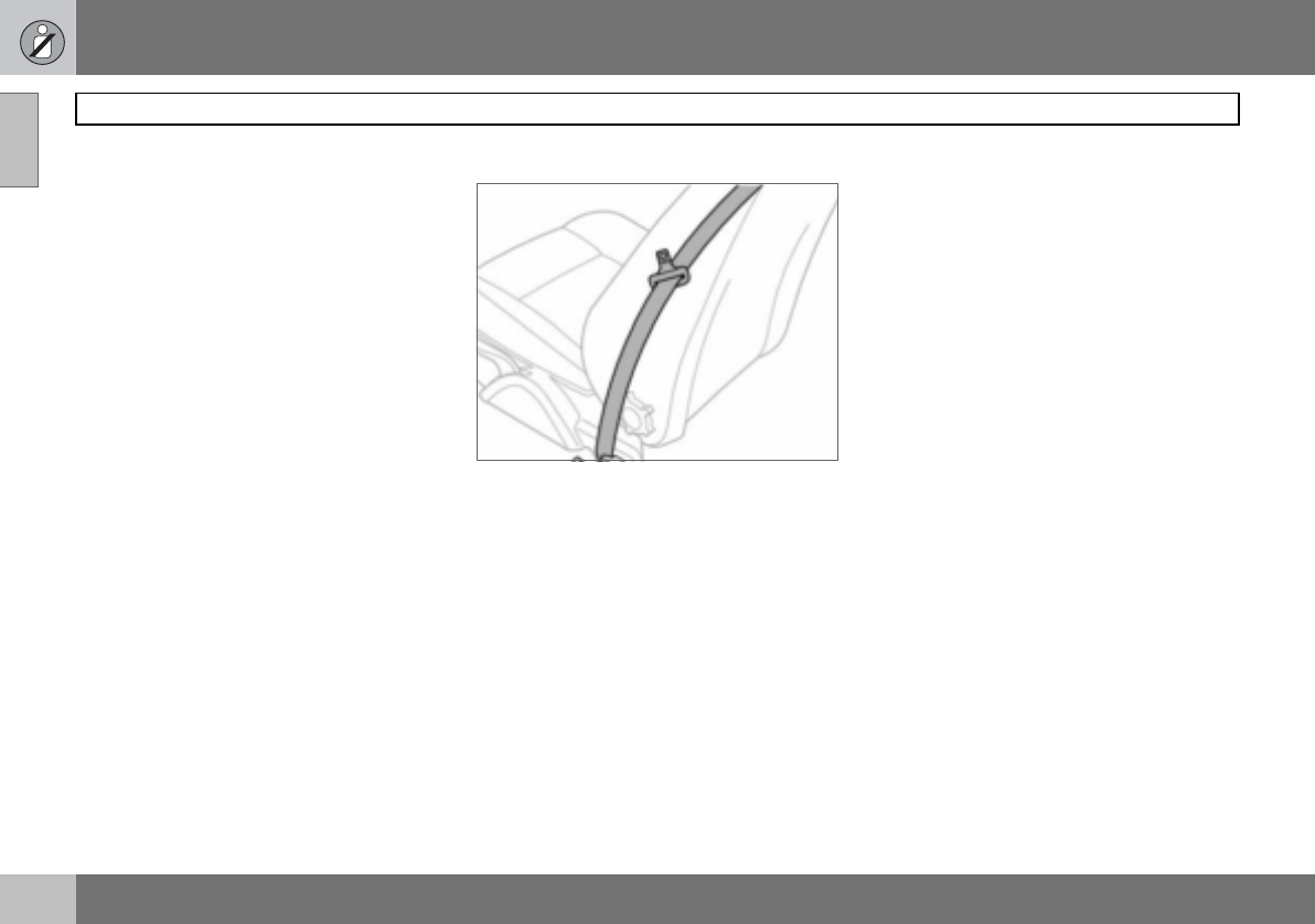
Seatbelts
01
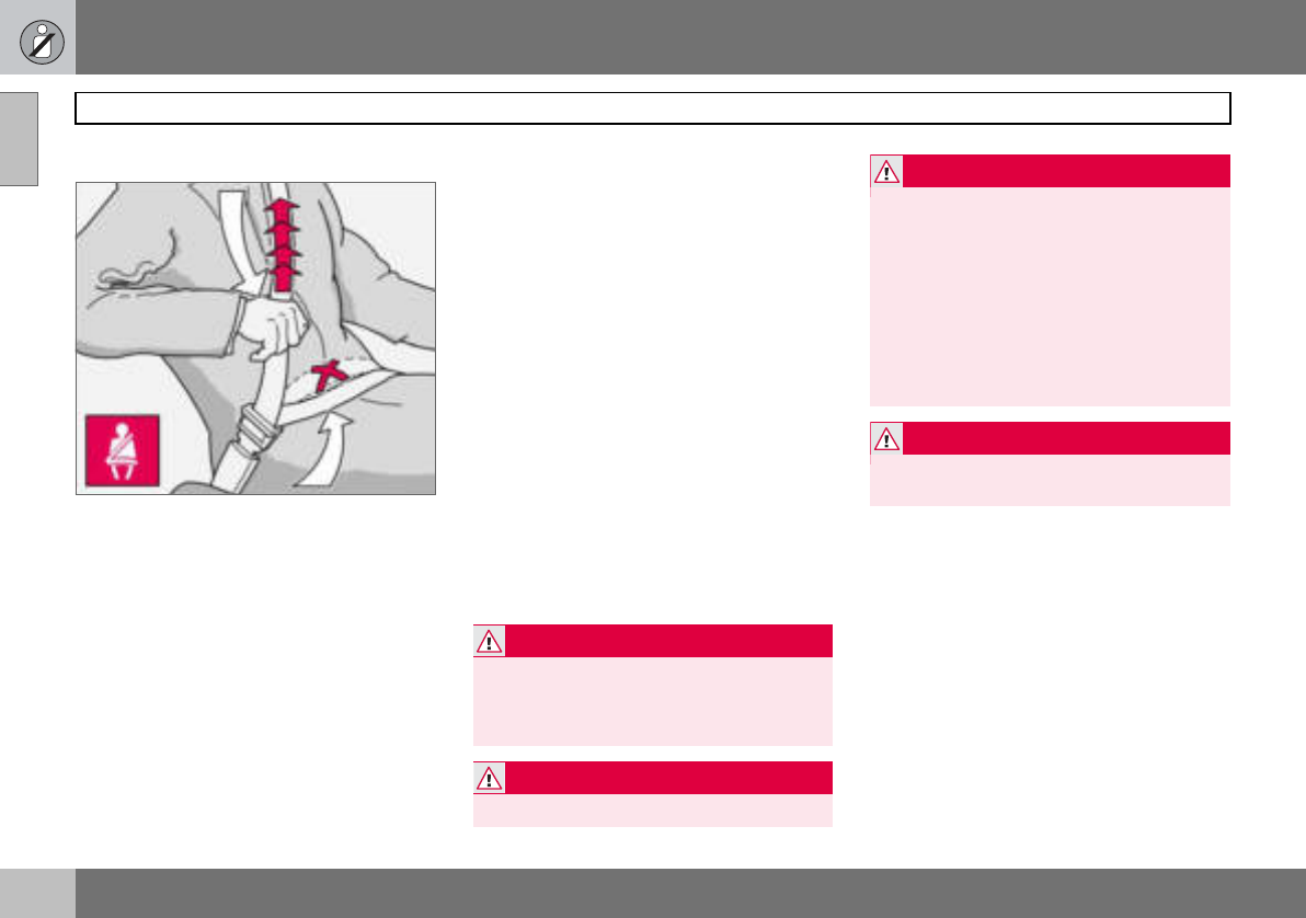
Always use a seatbelt
Tensioning the hip strap. The belt must be
positioned low down.
Heavy braking can have serious conse-
quences if the seatbelts are not used. Ensure
that all passengers use their seatbelts.
Putting on a seatbelt:
– Pull the belt out slowly and secure it by
pressing the buckle into the lock. A loud
"click" indicates that the belt has locked.
Releasing the belt
– Press the red lock button and then let the
belt retract. If the belt does not retract
fully, feed it in by hand so that it does not
hang loose.
The belt locks and cannot be withdrawn
• if it is pulled out too quickly
• during braking and acceleration
• if the car leans heavily.
It is important that the belt lies in contact
against the body so it can provide maximum
protection. Do not lean the backrest too far
back. The belt is designed to protect in a nor-
mal seating position.
Keep in mind the following:
• do not use clips or anything else that can
prevent the belt from fitting properly
• ensure the belt is not twisted or caught on
anything
• the hip strap must be positioned low down
(not over the abdomen)
• tension the hip strap over the lap by
pulling the diagonal shoulder belt as
illustrated
WARNING
The seatbelts and airbags interact. If a seat-
belt is not used or is used incorrectly, this
may diminish the protection provided by the
airbag in the event of a collision.
WARNING
Each belt is intended for one person only.
WARNING
Never modify or repair the belt yourself.
Contact an authorised Volvo workshop. If
the belt has been subjected to a major load,
such as in a collision, the entire belt must be
replaced. Some of the protective character-
istics of the belt may have been lost, even if
it appears to be undamaged. In addition, re-
place the belt if it is worn or damaged. The
new seatbelt must be type-approved and
intended for installation in the same position
as the replaced belt.
WARNING
The rear seat is designed for a maximum of
two passengers.
01 Safety
13
Seatbelts 01
Seatbelt reminder
An audio signal and indicator lamp remind
anyone not wearing a seatbelt to use one.
The audio reminder is speed-dependent. Re-
minder indicator lamps are located in the roof
console and combined instrument panel. At
low speed, the audio reminder will sound for
the first six seconds.
Child seats are not covered by the seatbelt
reminder system.
Rear seat
The seatbelt reminder in the rear seat has
two subfunctions:
• Provides information on which seatbelts
are being used in the rear seat. This is
shown on the information display. The
message is automatically cleared after
approx. 30 seconds or can be acknowl-
edged manually by pressing the READ
button.
• Provides a warning if one of the rear
seatbelts is unfastened during a journey.
This warning takes the form of a message
on the information display along with the
audio/visual signal. The warning ceases
when the belt is re-fastened or can be
acknowledged manually by pressing the
READ button.
The message on the information display
showing which belts are in use is always
available. Press the READ button to see
stored messages.
Certain markets
An audio signal and indicator lamp remind
the driver if not wearing a seatbelt to use one.
At low speed, the audio reminder will sound
for the first six seconds.
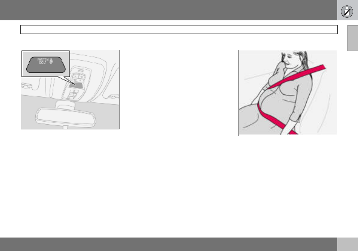
Seatbelts and pregnancy
The seatbelt should always be worn during
pregnancy. But it is crucial that it be worn in
the correct way. The diagonal section should
wrap over the shoulder then be routed be-
tween the breasts and to the side of the ab-
domen. The lap section should lay flat over
the thighs and as low as possible under the
abdomen. It must never be allowed to ride
upward. Remove all slack from the belt and
ensure that it fits close to the body. In addi-
tion, check that there are no twists in the belt.
As a pregnancy progresses, pregnant drivers
should adjust their seats and steering wheel
such that they can easily maintain control of
01 Safety
14
Seatbelts
01
the vehicle as they drive (which means they
must be able to easily operate the foot ped-
als and steering wheel). Within this context,
they should strive to position the seat with as
large a distance as possible between their
abdomen and the steering wheel.
Seatbelt tensioner
All the seatbelts are equipped with belt ten-
sioners. A mechanism in the belt tensioner
tightens the belt around the body in the event
of a sufficiently forceful collision. This pro-
vides more effective restraint by the belt for
passengers.
Seatbelt guide
The seatbelt guide is fitted on both the driver’s
seat and passenger seat.
The seatbelt guide is an aid for providing bet-
ter access to the seatbelt. When getting into
and out of the rear seat the seatbelt is re-
moved from the seatbelt guide and posi-
tioned furthest back on the seatbelt bar.
01 Safety
15
Airbag system 01
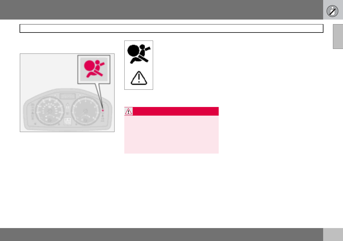
Warning symbol on the combined
instrument panel
The airbag system1 is continually monitored
by the system’s control module. The warning
symbol on the combined instrument panel il-
luminates when the ignition key is turned to
position I, II or III. The symbol goes out after
approx. seven seconds provided the airbag
system1 is fault-free.
As well as the warning sym-
bol, a message may appear
on the information display in
some cases. If the warning
symbol malfunctions, the
warning triangle illuminates
and the message SRS AIR-
BAG SERVICE URGENT ap-
pears in the information dis-
play. Contact an authorised
Volvo workshop immediately.
1Includes SRS and seatbelt tensioner, SIPS
and IC.
WARNING
If the warning symbol for the airbag system
remains on or illuminates while driving, it
means that the airbag system is not func-
tioning fully. The symbol can indicate a fault
in the seatbelt buckle, SIPS, SRS or IC sys-
tems. Contact an authorised Volvo work-
shop immediately.
01 Safety
16
Airbags (SRS)
01
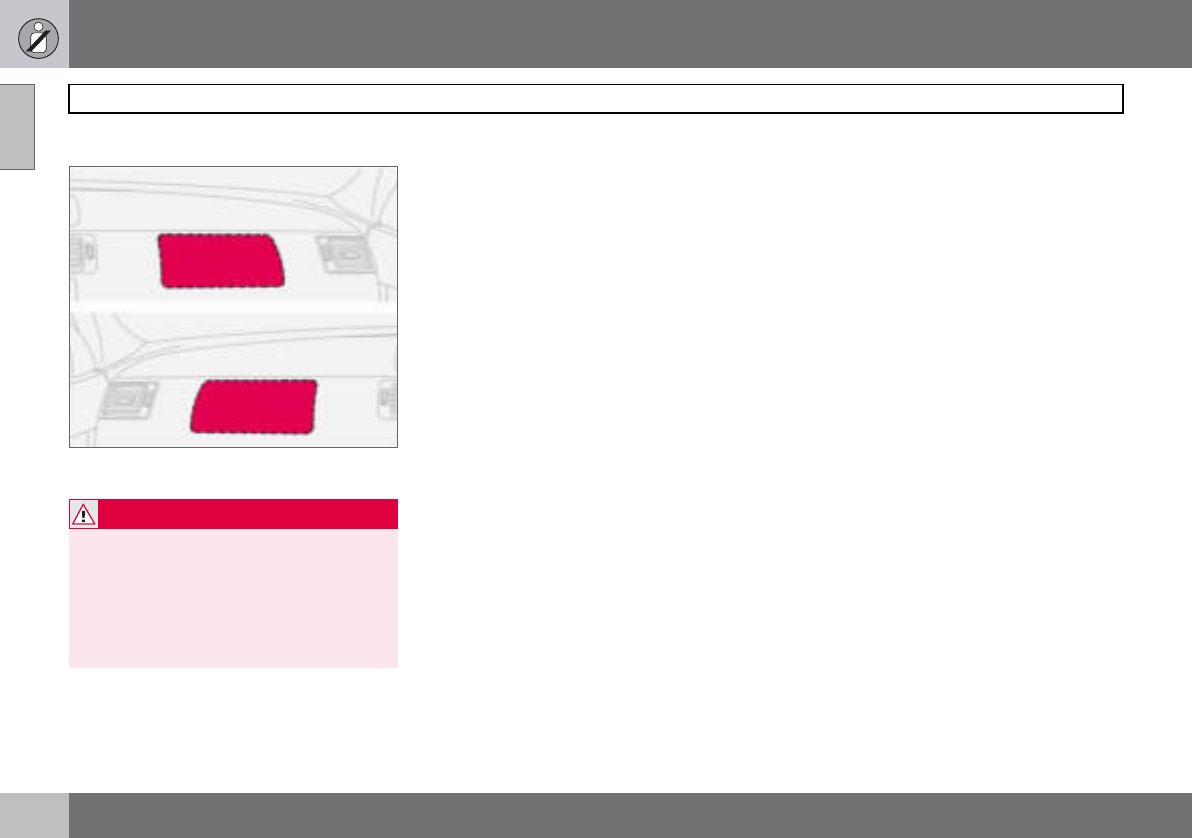
Airbag (SRS) on the driver’s side
The car has an SRS airbag (Supplemental
Restraint System) in the steering wheel to
supplement the protection afforded by the
seatbelt. This airbag is fitted into the centre
of the steering wheel. The steering wheel is
marked SRS AIRBAG.
Passenger airbag (SRS)
The car has an SRS airbag (Supplemental
Restraint System) to supplement the protec-
tion afforded by the seatbelt. The passenger
airbag1 is fitted behind a panel above the
glovebox. This panel is marked SRS
AIRBAG.
WARNING
The seatbelts and airbags interact. If a seat-
belt is not used or is used incorrectly, this
may diminish the protection provided by the
airbag in the event of a collision.
1Not all cars have a passenger airbag (SRS).
This can be unselected when the car is or-
dered.
WARNING
To minimise the risk of injury if the airbag
deploys, passengers must sit as upright as
possible with their feet on the floor and
back against the backrest. Seatbelts must
be secured.
WARNING
Never place a child in a child seat or on a
booster cushion in the front seat if the air-
bag (SRS) is activated1.
Never allow a child to stand or sit in front of
the front passenger seat. No one shorter
than 140 cm should ever sit in the front pas-
senger seat if the airbag (SRS) is activated.
Failure to follow the advice given above can
endanger the life of the child.
1For information on activated/deactivated air-
bag (SRS) see page 19.
01 Safety
17
Airbags (SRS) 01
SRS system
SRS system, left-hand drive.
The system consists of airbags and sensors.
A sufficiently violent collision trips the sen-
sors and the airbag(s) are inflated with hot
gas. To cushion the impact, the airbag de-
flates when compressed. When this occurs,
smoke escapes into the car. This is com-
pletely normal. The entire process, including
inflation and deflation of the airbag, occurs
within tenths of a second.
SRS system, right-hand drive.
NOTE
The sensors react differently depending on
the course of the collision and whether or
not the seatbelts on the driver and passen-
ger side are used. It is therefore possible
that only one (or none) of the airbags may
inflate in a collision. The SRS system sens-
es the force of the collision on the car and
adapts accordingly so that one or more air-
bags are deployed.
NOTE
The airbags have a function whereby their
capacities are adapted to the collision force
to which the car is subjected.
WARNING
Any repair must only be performed by an
authorised Volvo workshop.
Any interference in the SRS system could
cause malfunction and result in serious per-
sonal injury.
01 Safety
18
Airbags (SRS)
01
Location of the passenger airbag in left-hand
drive and right-hand drive cars
WARNING
Never interfere with SRS components in the
steering wheel or the panel above the
glovebox.
Objects and accessories must not be posi-
tioned or glued on or near the SRS AIR-
BAG panel (above the glovebox) or in the
area affected by a deployed airbag.
01 Safety
19
Activating/deactivating the airbag (SRS) 01
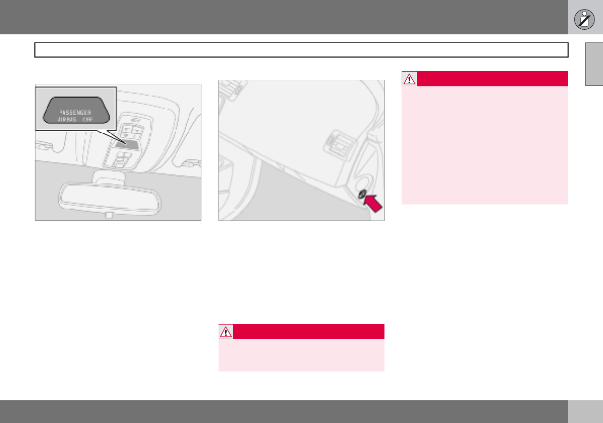
PACOS (option)
Indicator showing that the passenger airbag
(SRS) is deactivated.
The airbag (SRS) for the front passenger seat
can be deactivated using a switch. This is
necessary if a child seat is to be fitted there
for example.
Indicator
A text message on the roof panel indicates
that the front passenger airbag (SRS) is de-
activated.
Activating/deactivating
Switch for PACOS (Passenger Airbag Cut Off
Switch).
The switch is located on the passenger end
of the dashboard and is accessible when the
passenger door is open. Check that the
switch is in the required position. Volvo rec-
ommends that that the ignition key is used to
change position. (Other items with a shape
similar to a key can be used).
WARNING
If the car is equipped with a front passenger
airbag (SRS), but does not have PACOS,
the airbag will always be activated.
WARNING
Activated airbag (passenger seat):
Never place a child in a child seat or on a
booster cushion in the front passenger seat
when the airbag is activated. This applies to
everyone shorter than 140 cm.
Deactivated airbag (passenger seat): No
one taller than 140 cm should ever sit in the
front passenger seat when the airbag is de-
activated.
Failure to follow the advice given above can
endanger life.
01 Safety
20
Activating/deactivating the airbag (SRS)
01
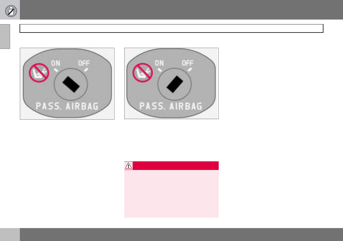
Switch position
Switch for SRS in ON position.
ON = Airbag (SRS) activated. With the switch
in this position, persons taller than 140 cm
can sit in the front passenger seat, although
never children in a child seat or on a booster
cushion.
Switch for SRS in OFF position.
OFF = Airbag (SRS) deactivated. With the
switch in this position, children in a child seat
or on a booster cushion can sit in the front
passenger seat, although never persons tall-
er than 140 cm.
WARNING
Do not allow anyone to sit in the front pas-
senger seat if the text message in the roof
panel indicates that the airbag (SRS) is de-
activated and if the warning symbol for the
airbag system is also displayed on the com-
bined instrument panel. This indicates that
there has been a severe malfunction. Con-
tact an authorised Volvo workshop immedi-
ately.
01 Safety
21
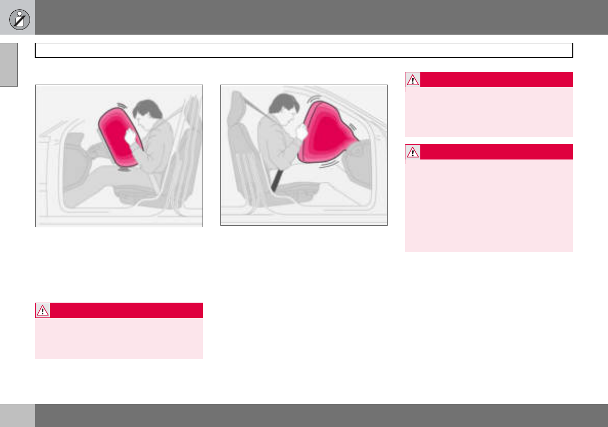
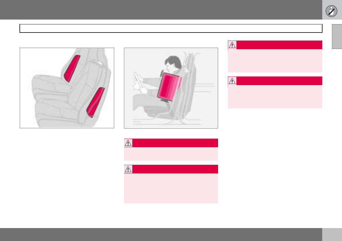
Side airbags (SIPS bags) 01
Side airbags – SIPS bags
Side airbag locations.
A large proportion of the collision force is
transferred by the SIPS (Side Impact Protec-
tion System) to beams, pillars, the floor, the
roof and other structural parts of the body.
The side airbags at the driver’s and front pas-
senger seats protect the chest area and are
an important part of the SIPS. The side air-
bags are located in the front seat backrests.
Inflated side airbag.
Child seats and side airbags
The side airbag does not diminish the protec-
tion provided by the car to children seated in
a child seat or on a booster cushion.
A child seat or booster cushion can be
placed on the front passenger seat provided
that the car does not have an activated1 pas-
senger airbag.
WARNING
Side airbags are a supplement to the SIPS
system. Always use a seatbelt.
WARNING
Any repair must only be performed by an
authorised Volvo workshop.
Any interference in the SIPS system could
cause malfunction and result in serious per-
sonal injury.
WARNING
Do not put objects in the area between the
outside of the seat and the door panel,
since this area is required by the side air-
bag.
WARNING
Use only Volvo genuine car seat covers, or
seat covers approved by Volvo. Other seat
covers may impede the operation of the
side airbags.
1For information on activated/deactivated air-
bag (SRS) see page 19
01 Safety
22
Side airbags (SIPS bags)
01
SIPS bags
Driver’s side
The SIPS bag system consists of side air-
bags and sensors. A sufficiently violent colli-
sion trips the sensors and the side airbag is
inflated. The airbag inflates between the oc-
cupant and the door panel and thereby cush-
ions the initial impact while deflating. The
side airbag is only normally deployed on the
side of the collision.
Passenger side
01 Safety
23
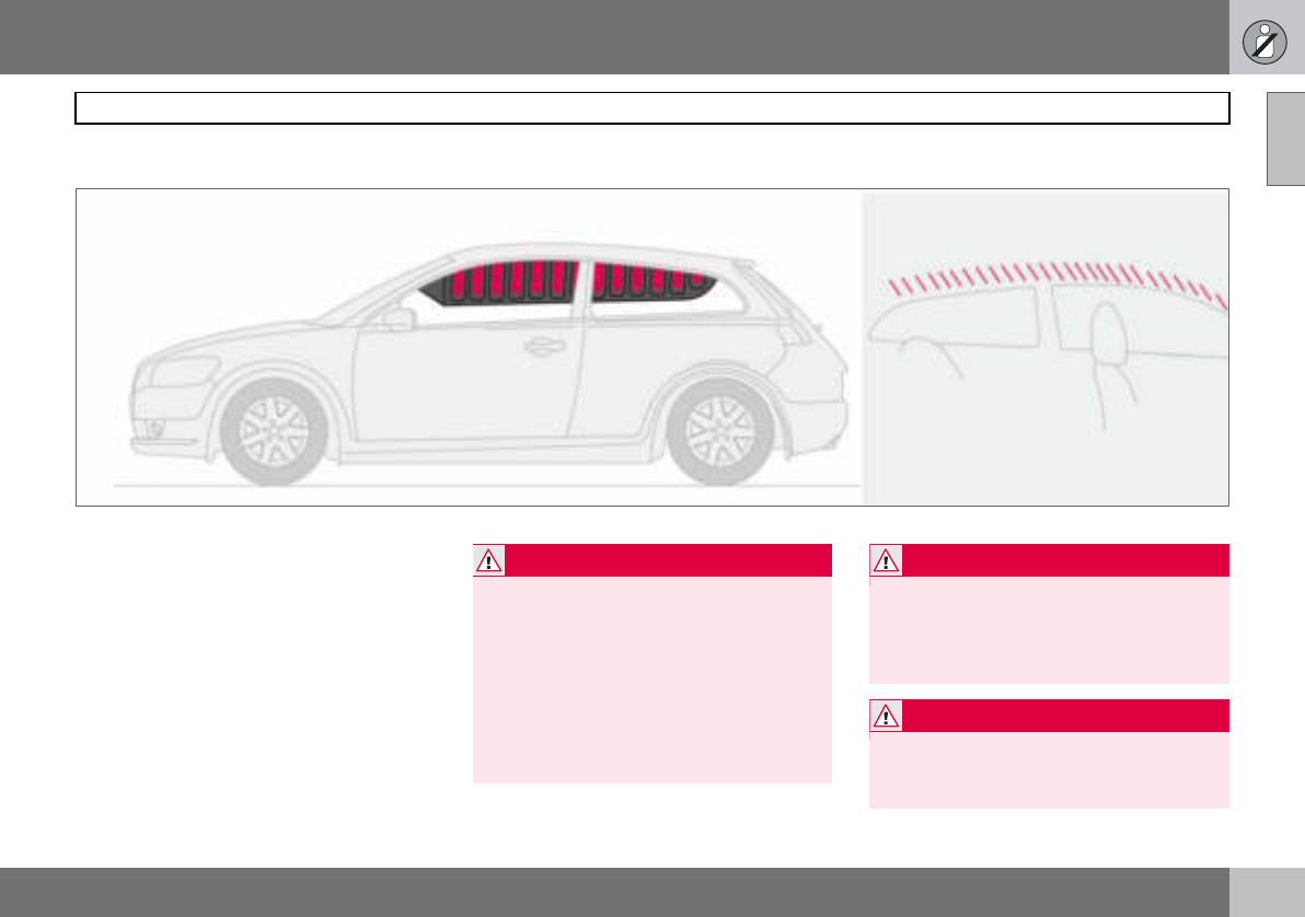
Inflatable Curtain (IC) 01
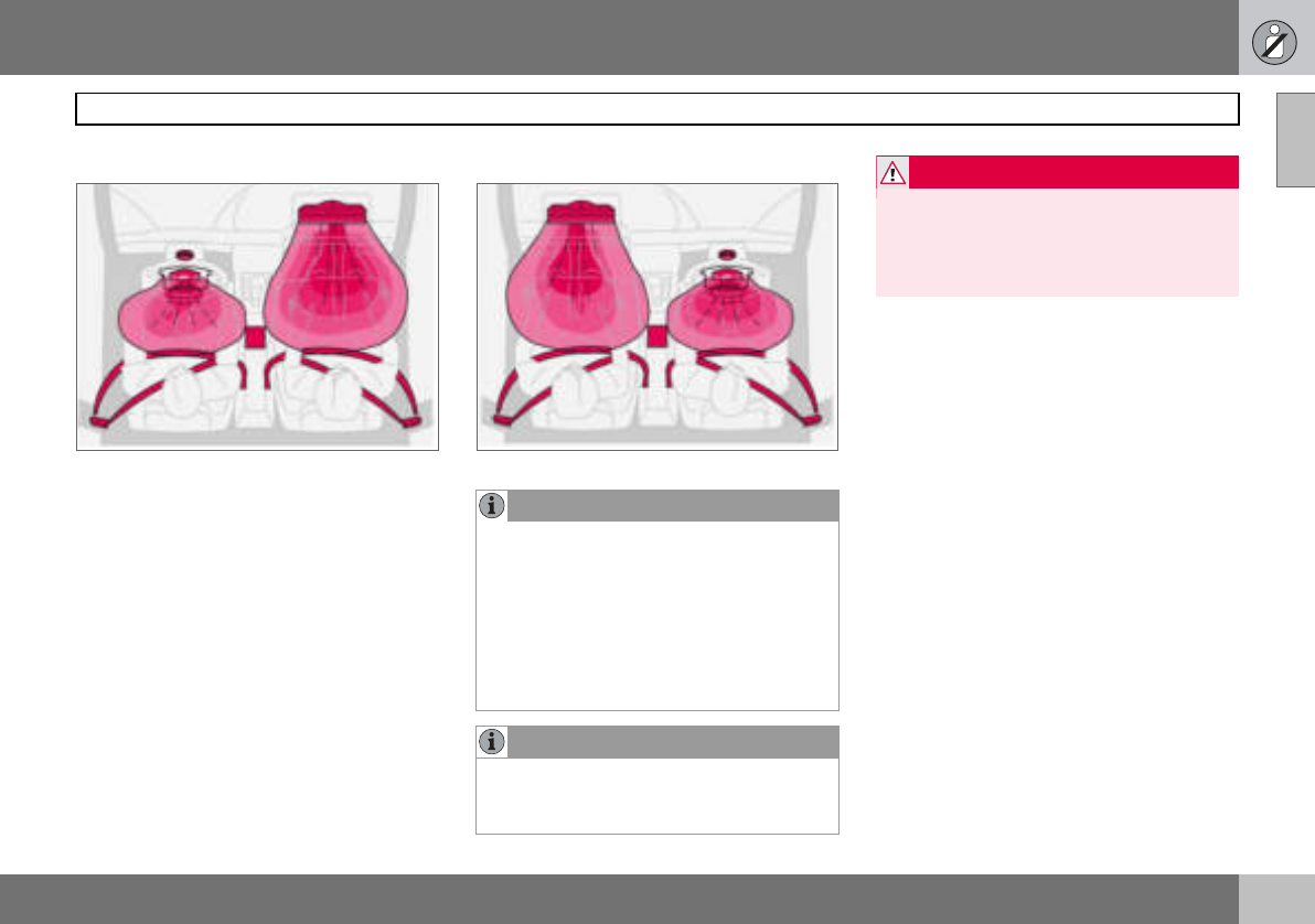
Properties
The inflatable curtain, IC (Inflatable Curtain),
is a supplement to the SIPS system. It is fit-
ted in the headlining along both sides of the
roof and protects both front and rear seat
passengers. A sufficiently violent collision
trips the sensors and the inflatable curtain is
inflated. The inflatable curtain helps to pre-
vent the driver and front seat passenger from
striking their heads on the inside of the car
during a collision.
WARNING
Never hang or attach heavy items onto the
handles in the roof. The hook is only de-
signed for light clothing (not for solid ob-
jects such as umbrellas for example).
Do not screw or install anything onto the
car’s headlining, door pillars or side panels.
This could compromise the intended pro-
tection. Only ever use Volvo genuine parts
that are approved for placement in these
areas.
WARNING
Do not load the car higher than 50 mm
under the top edge of the side windows.
Otherwise, the intended protection of the
inflatable curtain, which is concealed in the
headlining, may be compromised.
WARNING
The inflatable curtain is a supplement to the
seatbelts.
Always use a seatbelt.
01 Safety
24
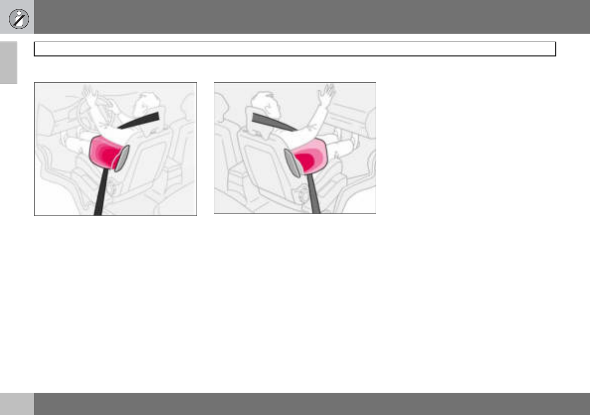
WHIPS
01
Protection against whiplash injury –
WHIPS
The whiplash protection system (WHIPS)
consists of energy absorbing backrests and
specially designed head restraints for the
front seats. The system is actuated by a rear-
end collision, where the angle and speed of
the collision, and the nature of the colliding
vehicle all have an influence.
Properties of the seat
When the WHIPS system is deployed, the
front seat backrests are lowered backward to
alter the seating position of the driver and
front seat passenger. This reduces the risk of
whiplash injury.
WHIPS system and child seats/
booster cushions
The WHIPS system does not diminish the
protection provided by the car to children
seated in a child seat or on a booster cush-
ion.
Correct seating position
For the best possible protection, the driver
and front seat passenger should sit in the
centre of the seat with as little space as pos-
sible between the head and the head re-
straint.
WARNING
The WHIPS system is a supplement to the
seatbelts. Always use a seatbelt.
WARNING
Never modify or repair the seat or WHIPS
system yourself. Contact an authorised
Volvo workshop.
01 Safety
25
WHIPS 01
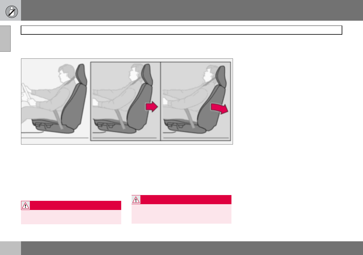
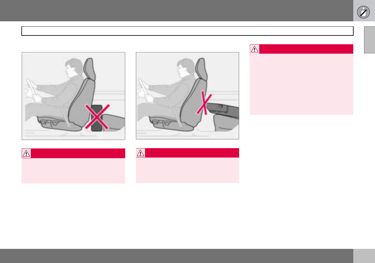
Do not obstruct the WHIPS system
WARNING
Do not squeeze rigid objects between the
rear seat cushion and the front seat back-
rest. Make sure you do not to obstruct the
function of the WHIPS system.
WARNING
If a rear seat backrest is folded down, the
corresponding front seat must be moved
forward so that it does not touch the folded
backrest.
WARNING
If a seat has been subjected to extreme
forces, such as due to a rear-end collision,
the WHIPS system must be checked by an
authorised Volvo workshop.
Part of the WHIPS system’s protective ca-
pacity may have been lost even if the seat
appears to be undamaged.
Contact an authorised Volvo workshop to
have the system checked even after a minor
rear-end collision.
01 Safety
26
When the systems deploy
01
If the airbags have been deployed, the fol-
lowing is recommended:
• Have the car transported to an authorised
Volvo workshop.Do not drive with de-
ployed airbags.
• Let an authorised Volvo workshop replace
components in the car’s safety system.
• Always contact a doctor.
System Tr i gg e re d
Seatbelt tensioner In a frontal collision and/or side-impact accident and/or overturning.
Airbags (SRS) In a frontal collision1.
Side airbags (SIPS) In a side-impact accident1.
Inflatable Curtain IC In a side-impact accident1.
Whiplash protection WHIPS In a rear-end collision.
1The bodywork of the car could be greatly deformed in a collision even without airbag deployment. A number of factors such as the rigidity and weight of the object
hit, the speed of the car, the angle of the collision etc. affects how the different safety systems of the car are triggered.
NOTE
The SRS, SIPS, IC and belt tensioner sys-
tems are deployed only once during a colli-
sion
WARNING
The airbag system’s control module is lo-
cated in the centre console. If the centre
console is drenched with water or other liq-
uid, disconnect the battery cables. Do not
attempt to start the car since the airbags
may deploy. Have the car transported to an
authorised Volvo workshop.
WARNING
Never drive with deployed airbags. They
can make steering difficult. Other safety
systems may also be damaged. The smoke
and dust created when the airbags are de-
ployed can cause skin and eye irritation/in-
jury after intensive exposure. In case of
irritation, wash with cold water. The rapid
deployment sequence and airbag fabric
may cause friction and skin burns.
01 Safety
27
Crash mode 01
Driving after a collision
If the car is involved in a collision, the text
CRASH MODE - SEE MANUAL may appear
on the information display. This means that
the car has reduced functionality. Crash
mode is a protective state that is enforced
when the collision may have damaged any of
the car’s vital functions, such as the fuel
lines, sensors for one of the safety systems,
or the brake system.
Attempting to start the car
First, check that no fuel is leaking from the
car. There must be no smell of fuel either.
If everything seems normal and you have
checked for indications of fuel leakage, you
may attempt to start the car.
Firstly, remove the ignition key and then rein-
sert it. The car’s electronics will then try to re-
set themselves to normal mode. Then try to
start the car. If CRASH MODE is still shown
on the display then the car must not be driv-
en or towed. Even if the car appears to be
driveable, hidden damage may make the car
impossible to control once moving.
Moving the car
If NORMAL MODE is shown after crash
mode has been reset, the car can be moved
carefully out of a dangerous position. Do not
move the car further than necessary.
WARNING
Never attempt to repair your car or reset the
electronics yourself if the car has been in
crash mode. This could result in personal
injury or the car not functioning as normal.
Always allow an authorised Volvo workshop
to check and restore the car to normal
mode after CRASH MODE has been dis-
played.
WARNING
Never, under any circumstances, attempt to
restart the car if it smells of fuel when the
crash mode message is displayed. Leave
the car at once.
WARNING
If the car is in crash mode it must not be
towed. It must be transported to an author-
ised Volvo workshop.
01 Safety
28
Child safety
01
Children should sit comfortably and
safely
The position of a child in the car and the
choice of equipment is dictated by the child’s
weight and size. For more information, see
page 30.
Children of all ages and sizes must always sit
correctly secured in the car. Never allow a
child to sit on the knee of a passenger.
Volvo’s own child safety equipment is de-
signed for your car. Use Volvo genuine
equipment to best ensure that the mounting
points and attachments are correctly posi-
tioned and are sufficiently strong.
You may place:
• a child seat or booster cushion on the
front passenger seat, provided the pas-
senger airbag is not activated1.
• a rear-facing child seat in the rear seat that
uses the back of the front seat as support.
Child seats and airbags
Child seats and airbags are not compatible.
Always place a child in the rear seat if the
passenger airbag is activated1. A child in a
child seat on the front passenger seat may
suffer serious injury if the airbag deploys.
Location of airbag decal in door opening on front
passenger side
NOTE
Regulations regarding the placement of
children in cars vary from country to coun-
try. Check what does apply.
1For information on activated/deactivated air-
bag (SRS) see page 19.
WARNING
Persons shorter than 140 cm may only sit in
the front passenger seat if the passenger
airbag is deactivated.
WARNING
Never place a child in a child seat or on a
booster cushion in the front seat if the air-
bag (SRS) is activated1. Failure to follow
this advice can endanger the life of the
child.
1For information on activated/deactivated air-
bag (SRS), see page 19.
01 Safety
29
Child safety 01
Decal located on instrument panel end face. Decal located on instrument panel end face
(Australia only).

01 Safety
30
Child safety
01
Placement of children in the car
Weight/age Front seat1Rear seat
<10 kg
(0–9 months) Rear-facing child seat, secured with
seatbelt and straps. Use a protective
cushion between the child seat and the
dashboard.
L2: Type approval no. E5 03135
Rear-facing child seat, secured with
seatbelt, support legs, straps and
attachment eye3.
L2: Type approval no. E5 03135
9–18 kg
(9–36 months) Rear-facing child seat, secured with
seatbelt and straps. Use a protective
cushion between the child seat and the
dashboard.
L2: Type approval no. E5 03135
Rear-facing child seat, secured with
seatbelt, support legs, straps and
attachment eye.3
L2: Type approval no. E5 03135
15–36 kg
(3–12 years) Booster cushion with or without
backrest.
L2: Type approval no. E5 03139
Booster cushion with or without
backrest.
L2: Type approval no. E5 03139
1For information on activating/deactivating the airbag (SRS), see page 19.
2L: Suitable for certain child seats as listed in the specified type approval. Child seats can be vehicle-specific,
limited, semi-universal or universal.
3To install a rear-facing child seat in the rear seat, contact an authorised Volvo dealer to have the mounting points
installed.
01 Safety
31
Child safety 01
Fitting a child seat
Volvo has child safety products that are de-
signed for and tested by Volvo.
When using other products that are available
on the market, it is important to read the fit-
ting instructions included with the product.
• Do not attach the straps for the child seat
to the horizontal adjustment bar, springs,
rails or beams under the seat. Sharp
edges can damage the straps.
• Allow the back of the child seat to rest
against the dashboard. This applies to
cars without a passenger airbag, or where
the airbag is deactivated.
ISOFIX fixture system for child seats
(option)
The outer rear seats have ISOFIX mounting
points for child seats. Contact a Volvo dealer
for further information on child safety equip-
ment.
WARNING
Booster cushions/child seats with steel
braces or some other design that could rest
on the seatbelt buckle’s opening button
must not be used, as they could cause the
seatbelt buckle to open accidentally.
Do not allow the upper section of the child
seat to rest against the windscreen.
WARNING
Never place the child seat in the front seat if
the car is equipped with an activated1 front
passenger airbag. If problems arise when
fitting child safety products, contact the
manufacturer for clearer instructions.
1For information on activated/deactivated airbag
(SRS), see page 19.

32
Overview, left-hand drive car ...................................................................34
Overview, right-hand drive car .................................................................36
Driver’s door control panel .......................................................................38
Combined instrument panel .....................................................................39
Indicator and warning symbols ................................................................40
Information display ...................................................................................43
Electrical socket and switch, centre console ...........................................45
Lighting panel ...........................................................................................46
Left-hand stalk switch ..............................................................................48
Right-hand stalk switch ...........................................................................50
Cruise control (option) ..............................................................................52
Steering wheel keypad (option) ................................................................54
Steering wheel adjustment, hazard warning flashers ..............................55
Parking brake, electrical socket ...............................................................56
Power windows ........................................................................................57
Rearview and door mirrors .......................................................................59
Power sunroof (option) .............................................................................62
Personal preferences ...............................................................................64
02
INSTRUMENTS AND CONTROLS
02 Instruments and controls
34
Overview, left-hand drive car
02

02 Instruments and controls
35
Overview, left-hand drive car
02
1. Steering wheel adjustment
2. Bonnet release
3. Control panel
4. Direction indicators, main beam, trip computer
5. Lighting, fuel filler flap opener
6. Door handle, lock button.
7. Air vents, dashboard
8. Air vent for side window
9. Cruise control
10.Horn, airbag
11.Combined instrument panel
12.Keypad for infotainment system
13.Windscreen wipers, washer and headlamp washers
14.Ignition switch
15.Sunroof controls
16.No function
17.Deactivation of alarm detectors, deadlocks
18.Interior lighting, switch
19.Reading lamp, left-hand side
20.Reading lamp, right-hand side
21.Seatbelt reminder
22.Interior rearview mirror
23.Display for climate control and infotainment system
24.Infotainment system
25.Controls for climate control, infotainment system and personal
preferences
26.Climate control
27.Gear lever
28.Hazard warning flashers
29.Door handle
30.Glovebox
31.Parking brake
32.Electrical socket/cigarette lighter
33.Blind Spot Information System, BLIS
34.Switch, optional equipment
02 Instruments and controls
36
Overview, right-hand drive car
02

02 Instruments and controls
37
Overview, right-hand drive car
02
1. Switch, optional equipment
2. Blind Spot Information System, BLIS
3. Electrical socket, cigarette lighter
4. Parking brake
5. Control panel
6. Glovebox
7. Door handle
8. Air vent for side window
9. Air vents, dashboard
10.Gear lever
11.Climate control
12.Controls for climate control, infotainment system and personal
preferences
13.Infotainment system
14.Display for climate control and infotainment system
15.Interior rearview mirror
16.Seatbelt reminder
17.Interior lighting, switch
18.Reading lamp, left-hand side
19.Reading lamp, right-hand side
20.No function
21.Deactivation of alarm detectors, deadlocks
22.Sunroof controls
23.Ignition switch
24.Windscreen wipers and washer, headlamp washers
25.Cruise control
26.Combined instrument panel
27.Horn, airbag
28.Keypad for infotainment system
29.Hazard warning flashers
30.Door handle, lock button
31.Lighting, fuel filler flap opener
32.Direction indicators, main beam, trip computer
33.Bonnet release
34.Steering wheel adjustment
02 Instruments and controls
38
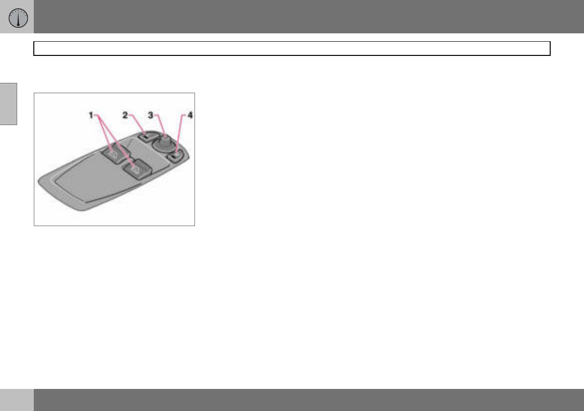
Driver’s door control panel
02
Driver’s door control panel
1. Power windows
2. Door mirror, left-hand side
3. Door mirrors, setting
4. Door mirror, right-hand side
02 Instruments and controls
39
Combined instrument panel
02
1. Speedometer.
2. Direction indicators, left.
3. Warning symbol.
4. Information display – The display
presents information or warning mes-
sages, outside temperature and the
time. When the outside temperature is
between +2 C and –5 C, a snowflake
symbol appears on the display. This
warns of icy roads. The outside tem-
perature gauge may show a slightly
high reading after the car has been
stationary.
5. Information symbol.
6. Direction indicator, right.
7. Tachometer – Indicates engine speed
in thousands of revolutions per minute
(rpm).
8. Indicator and information symbols.
9. Fuel gauge.
10.Button for trip meter – Used to measure
short distances. Short presses on the
button switches between the two trip
meters T1 and T2. A long press (more
than 2 seconds) resets an active trip
meter to zero.
11.Display – Display for automatic gear
position, rain sensor, odometer, trip
meter and cruise control.
12.Main beam indicator.
13.Knob for clock – Turn the knob to
adjust the time.
14.Temperature gauge – Displays the tem-
perature of the engine cooling system.
A message will appear on the display if
the temperature becomes too high and
the gauge goes into the red zone. Bear
in mind that extra lights placed in front
of the air intake, for example, reduce
the cooling capacity at high outside
temperatures and high engine loads.
15.Indicator and warning symbols.
02 Instruments and controls
40
Indicator and warning symbols
02
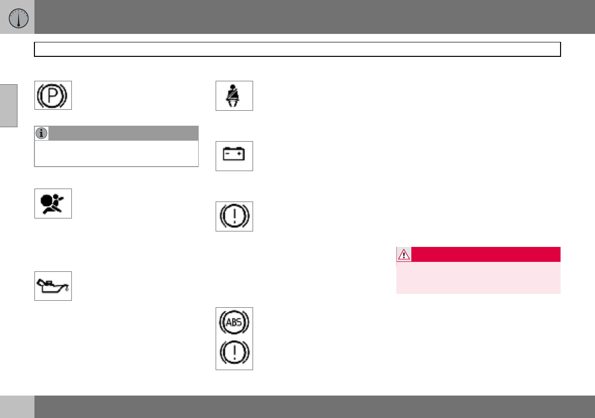
Functionality check, symbols
All indicator and warning symbols1 illuminate
when the ignition key is turned to position II
before starting. This is to check that the sym-
bols are working. When the engine starts, all
the symbols should go out except the hand-
brake symbol, which only goes out when the
brake is disengaged.
If the engine does not start
within five seconds, all sym-
bols extinguish except the
symbols for a fault in the car’s
emissions system and for low
oil pressure. Certain symbols
may have no function, de-
pending on the car’s specifications.
Symbols in the centre of the
instrument panel
The red warning symbol illumi-
nates when a fault has been in-
dicated which could affect the
safety and/or driveability of the
car. An explanatory text is
shown on the information display at the same
time. Symbol and message text are visible
until the fault has been rectified.
The warning symbol can also illuminate in
conjunction with other symbols.
– Stop in a safe place. Do not drive the car
further.
– Read the information on the information
display.
– Rectify the fault as instructed or contact
an authorised Volvo workshop.
When one of the car’s systems
does not behave as intended,
the yellow information symbol il-
luminates and a text appears on
the information display. The
message text is cleared using the READ but-
ton, see page 43, or it disappears automati-
cally after two minutes.
The yellow information symbol can also illu-
minate in conjunction with other symbols.
1For certain engine variants, the symbol for low
oil pressure is not used. Warnings are made
via display text, see page 174.
NOTE
When the message text TIME FOR
REGULAR SERVICE is shown, the symbol
lamp and message text are cleared using
the READ button, or disappear automati-
cally after two minutes.
02 Instruments and controls
41
Indicator and warning symbols
02
Indicator symbols – left-hand side
1. Fault in car’s emissions system
Drive to an authorised Volvo
workshop to have the system
checked.
2. ABS fault
If this symbol illuminates then the
system is not working. The car’s
regular brake system continues
to work, but without the ABS
function.
– Stop the car in a safe place and turn off
the engine.
– Restart the engine.
– Drive to an authorised Volvo workshop to
have the ABS checked if the symbol re-
mains lit.
3. Rear fog lamp
This symbol is lit when the rear
fog lamp is on.
4. Stability system STC or DSTC
For information on the system’s
functions and symbols, see
page 121.
5. No function
6. Engine preheater (diesel)
This symbol illuminates during
engine preheating. Preheating
occurs when the temperature
is below –2 C. The car can
be started once the symbol
goes out.
7. Low level in fuel tank
This symbol illuminates when
there are approximately 8 litres
of usable fuel left in a petrol-en-
gined car, or approximately
7 litres in a diesel-engined car.
Indicator symbols – right-hand side
1. Indicator symbol for trailer
This symbol flashes when the di-
rection indicators are used and
the trailer is connected. If the
symbol does not flash then one
of the lamps on the trailer or the car is faulty.
02 Instruments and controls
42
Indicator and warning symbols
02
2. Parking brake applied
The lamp illuminates when the
parking brake is applied. Always
pull the parking brake lever to the
end position.
3. Airbags – SRS
If this symbol remains on or illu-
minates while driving, it means a
fault has been detected in the
seatbelt buckle, SRS, SIPS, or IC
systems. Drive immediately to an authorised
Volvo workshop to have the system checked.
4. Low oil pressure1
If this symbol illuminates during
driving then the engine’s oil pres-
sure is too low. Stop the engine
immediately and check the en-
gine oil level, top up if necessary. If the sym-
bol lights up and the oil level is normal, con-
tact an authorised Volvo workshop.
5. Seatbelt reminder
This symbol lights if someone in
a front seat has not put on their
seatbelt or if someone in a rear
seat has taken off their seatbelt.
6. Alternator not charging
If this symbol illuminates while
driving, a fault has occurred in
the electrical system. Contact an
authorised Volvo workshop.
7. F a u l t i n b r a k e s y s t e m
If this symbol lights, the brake
fluid level may be too low.
– Stop the car in a safe place and check the
level in the brake fluid reservoir, see
page 177. If the level in the reservoir is
below MIN, the car should not be driven
any further. Have the car transported to an
authorised Volvo workshop to have the
brake system checked.
If the BRAKE and ABS symbols
illuminate at the same time, there
may be a fault in the brake force
distribution system.
– Stop the car in a safe place and turn off
the engine.
– Restart the engine.
– If both symbols extinguish, continue driv-
ing.
– If the symbols remain on, check the level
in the brake fluid reservoir. See page 177.
– If the brake fluid level is normal but the
symbols are still lit, the car can be driven,
with great care, to an authorised Volvo
workshop to have the brake system
checked.
– If the level in the reservoir is below MIN,
the car should not be driven any further.
Have the car transported to an authorised
Volvo workshop to have the brake system
checked.
NOTE
The lamp illuminates irrespective of how
hard the parking brake is applied.
1For certain engine variants, the symbol for low
oil pressure is not used. Warnings are made
via display text, see page 174.
WARNING
If the BRAKE and ABS symbols are illumi-
nated at the same time, there is a risk that
the rear end will skid during heavy braking.
02 Instruments and controls
43
Information display
02
Reminder – doors not closed
If one of the doors, the bonnet1 or the tailgate
is not properly closed, the driver will be re-
minded of this.
Low speed
If the car is travelling at a speed
lower than approx. 7 km/h, the
information symbol will illuminate
and one of the following texts will
be shown on the display:
DRIVER DOOR OPEN, PASSENGER DOOR
OPEN, or ENGINE HOOD OPEN. Stop the
car as soon as it is safe to do so and close
the open door or bonnet.
High speed
If the car is moving faster than
approx. 7 km/h, the symbol illu-
minates and one of the texts in-
dicated in the previous para-
graph appears in the display.
Tailgate reminder
If the tailgate is open, this infor-
mation symbol will illuminate and
TAILGATE OPEN will appear on
the display.
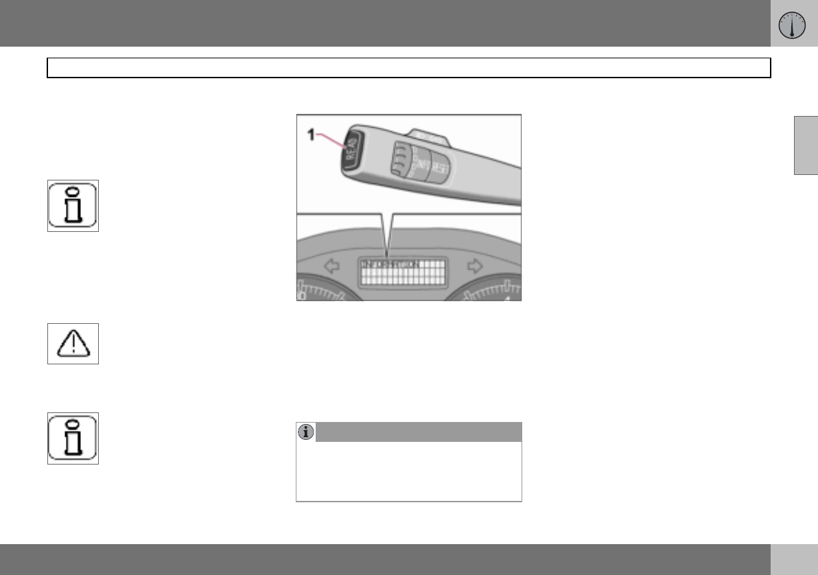
Messages
When a warning or indicator symbol illumi-
nates, a message appears on the information
display.
–Press the READ button (1).
Switch between messages with the READ
button. Error messages are stored in a mem-
ory list until the fault is rectified.
1Only cars with alarm.
NOTE
If a warning message appears while you are
using the trip computer, the message must
be read (press READ) before the previous
activity can be resumed.
02 Instruments and controls
44
Information display
02
Message Specification
STOP SAFELY Stop the car in a safe manner and turn off the engine. Serious risk of damage.
STOP ENGINE Stop the car in a safe manner and turn off the engine. Serious risk of damage.
SERVICE URGENT Have the car checked by an authorised Volvo workshop immediately.
SEE MANUAL Read the owner’s manual.
SERVICE REQUIRED Have the car checked by an authorised Volvo workshop as soon as possible.
TIME FOR REGULAR SERVICE Time for regular service at an authorised Volvo workshop. The timing is determined by the number of
kilometres driven, number of months since the last service and engine running time.
CHECK OIL LEVEL Check the oil level. The message is shown every 10 000 km1. For information on checking the oil
level, see page 175.
SOOT FILTER FULL SEE MANUAL Diesel particle filter requires regeneration, see page 111.
STC/DSTC SPIN CONTROL OFF The function of the stability and traction control system is reduced, see page 122 for more variants.
1Certain engine variants
02 Instruments and controls
45
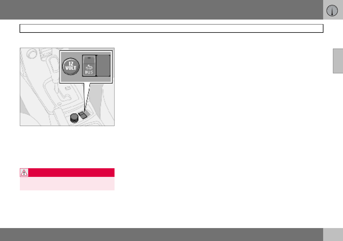
Electrical socket and switch, centre console
02
12 V electrical socket
Electrical socket, BLIS and extra equipment
The electrical socket can be used for 12 V
accessories, such as mobile phone chargers
and coolers. The maximum current is 10 A.
For the socket to supply current, the ignition
key must be in at least position I.
Cigarette lighter (option)
Activate the lighter by pushing in the button.
The button pops out when the lighter is hot.
Pull out the lighter and light a cigarette on the
heated coils.
Extra equipment
Space for an extra switch for retrofitted
equipment.
WARNING
Always leave the plug in the socket when
the socket is not in use.
02 Instruments and controls
46
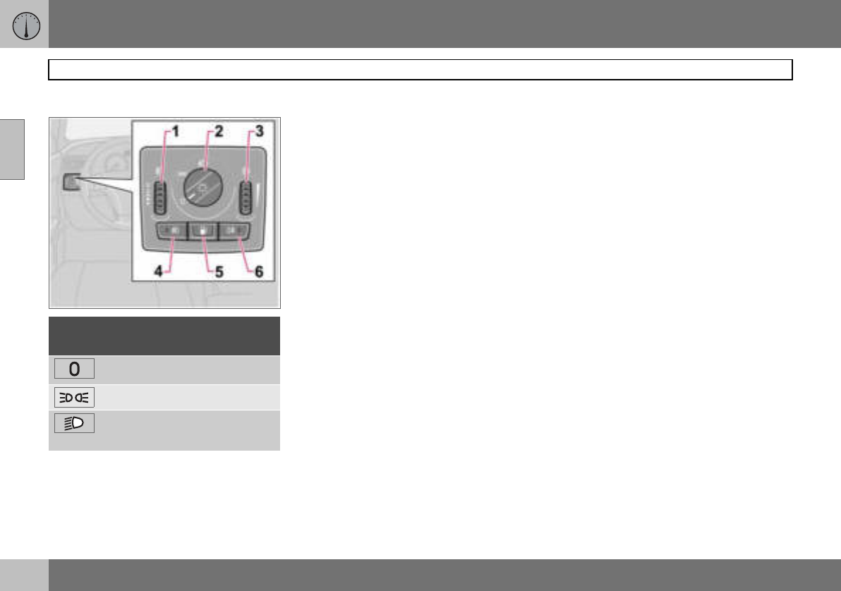
Lighting panel
02
Headlamp levelling
The load in the car changes the vertical align-
ment of the headlamp beam, which could
dazzle oncoming motorists. Avoid this by ad-
justing the height of the beam.
– Turn the ignition key to position II.
– Turn the headlamp control (2) to one of the
end positions.
– Roll the control (1) up or down respective-
ly to raise or lower beam alignment.
Cars with Bi-Xenon headlamps1 have auto-
matic headlamp levelling, so there is no
control (1).
Position/parking lamps
Position/parking lamps can be switched on
irrespective of ignition key position.
– Turn the headlamp control (2) to the centre
position.
When the ignition key is in position II the po-
sition/parking lamps and number plate light-
ing are always on.
Headlamps
Automatic dipped beam (certain
countries)
Dipped beam comes on automatically when
the ignition key is turned to position II, ex-
cept when the headlamp control (2) is in the
centre position. If necessary, the automatic
dipped beam can be deactivated by an au-
thorised Volvo workshop.
Automatic dipped beam, main beam
– Turn the ignition key to position II.
– Dipped beam is activated by means of
turning the headlamp control (2) clockwise
to the end position.
– Main beam is activated by means of mov-
ing the left-hand stalk switch towards the
steering wheel to the end position and
releasing it, see page 48.
The lamps are switched off automatically
when the ignition key is turned to position
I or 0.
Instrument lighting
The instrument lighting is switched on when
the ignition key is in position II and the head-
lamp control (2) is in one of the end positions.
The lighting is automatically dimmed during
the day and can be controlled manually at
night.
– Roll the control up or down (3) for brighter
or dimmer lighting.
Posi-
tion Specification
Automatic/deactivated dipped
beam. Only main beam flash.
Position/parking lamps
Automatic dipped beam. Main
beam and main beam flash work
in this position.
1Option.
02 Instruments and controls
47
Lighting panel
02
Enhanced display lighting
To facilitate reading the odometer, trip meter,
clock and outside temperature gauge, these
illuminate when the car is unlocked and when
the key is removed from the ignition switch.
The displays extinguish when the car is
locked.
Fog lamps
Front fog lamps (option)
The front fog lamps can be switched on
along with the headlamps or the position
lamps/parking lamps.
– Press the button (4).
The light in the button (4) illuminates when
the front fog lamps are switched on.
Rear fog lamp
The rear fog lamp can only be switched on
with the headlamps or the front fog lamps.
– Press the button (6).
The rear fog lamp indicator symbol on the
combined instrument panel and the light in
the button (6) illuminate when the rear fog
lamp is switched on.
Fuel filler flap
Press button (5) to open the fuel filler flap
when the car is unlocked, see page 110.
NOTE
Regulations for use of fog lamps vary from
country to country.
02 Instruments and controls
48
Left-hand stalk switch
02
Stalk switch positions
1. Short flash sequence, direction indicators
2. Continuous flash sequence, direction
indicators
3. Main beam flash
4. Switching, main and dipped beam, and
home safe lighting
Direction indicators
Continuous flash sequence
– Move the stalk switch up or down to end
position (2).
The stalk switch remains in its end position
and is moved back manually, or automatical-
ly by steering wheel movement.
Short flash sequence
– Move the stalk switch up or down to
position (1) and release.
The direction indicators flash three times and
the stalk switch returns to its home position.
Switching, main and dipped beam
The ignition key must be in position II for
main beam to be switched on.
– Turn the headlamp control clockwise to
the end position, see page 46.
– Move the stalk switch towards the steer-
ing wheel to the end position (4) and re-
lease.
Main beam flash
– Move the stalk switch gently towards the
steering wheel to position (3).
Main beam comes on until the stalk switch is
released.
Home safe lighting
Some of the exterior lighting can be kept
switched on to work as home safe lighting af-
ter the car has been locked. The standard
delay is 30 seconds1, but can be changed to
60 or 90 seconds, see page 65.
– Remove the key from the ignition switch.
– Move the stalk switch towards the steer-
ing wheel to the end position (4) and re-
lease.
– Get out of the car and lock the door.
1Factory settings.
02 Instruments and controls
49
Left-hand stalk switch
02
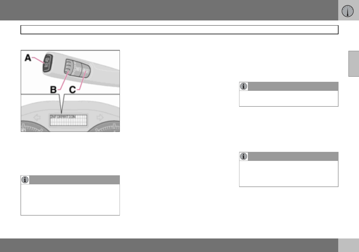
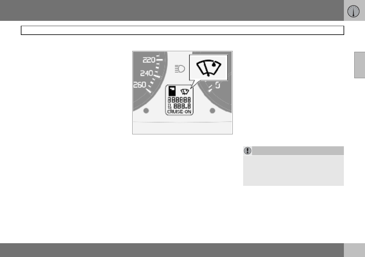
Trip computer (option)
Controls
To scroll through trip computer information
turn the thumbwheel (B) either up or down in
steps. Continue turning to return to the start-
ing point.
Functions
The trip computer displays the following in-
formation:
•AVERAGE SPEED
•ACTUAL SPEED MPH1
•INSTANTANEOUS
•AVERAGE
•KILOMETRES TO EMPTY TANK
•STC/DSTC, see page 121
AVERAGE SPEED
When the ignition is switched off, the average
speed is stored and used as the basis of the
new value when you continue driving. Reset
using the RESET button (C).
ACTUAL SPEED1
Current speed is displayed in mph.
INSTANTANEOUS
Current fuel consumption is calculated every
second. The information on the display is up-
dated every couple of seconds. When the car
is stationary, "---- " appears on the display.
During the period for regeneration2 fuel con-
sumption may increase, see page 111.
AVERAGE
The average fuel consumption since the last
reset (RESET). The average fuel consump-
tion is stored when the ignition is switched
off and remains until the function is reset. Re-
set using the RESET button (C).
KILOMETRES TO EMPTY TANK
The range to empty is calculated based on
the average fuel consumption over the last
30 km. When the range to empty is shorter
than 20 km then "----" is shown on the
display.
Resetting
– Select AVERAGE SPEED or AVERAGE
– Press and hold the RESET button (C) for
at least five seconds to reset the average
speed and average consumption at the
same time.
NOTE
If a warning message interrupts while you
are using the trip computer, this message
must be acknowledged. Acknowledge by
pressing the READ button (A) and revert to
the trip computer function.
1Certain countries.
2Only applies to diesel cars with particle filter.
NOTE
There may be a slight error in the reading if
a fuel-driven heater is used.
NOTE
There may be a slight error in the reading if
fuel consumption is changed due to a
change in driving style or if a fuel-driven
heater is used for example.
02 Instruments and controls
50
Right-hand stalk switch
02
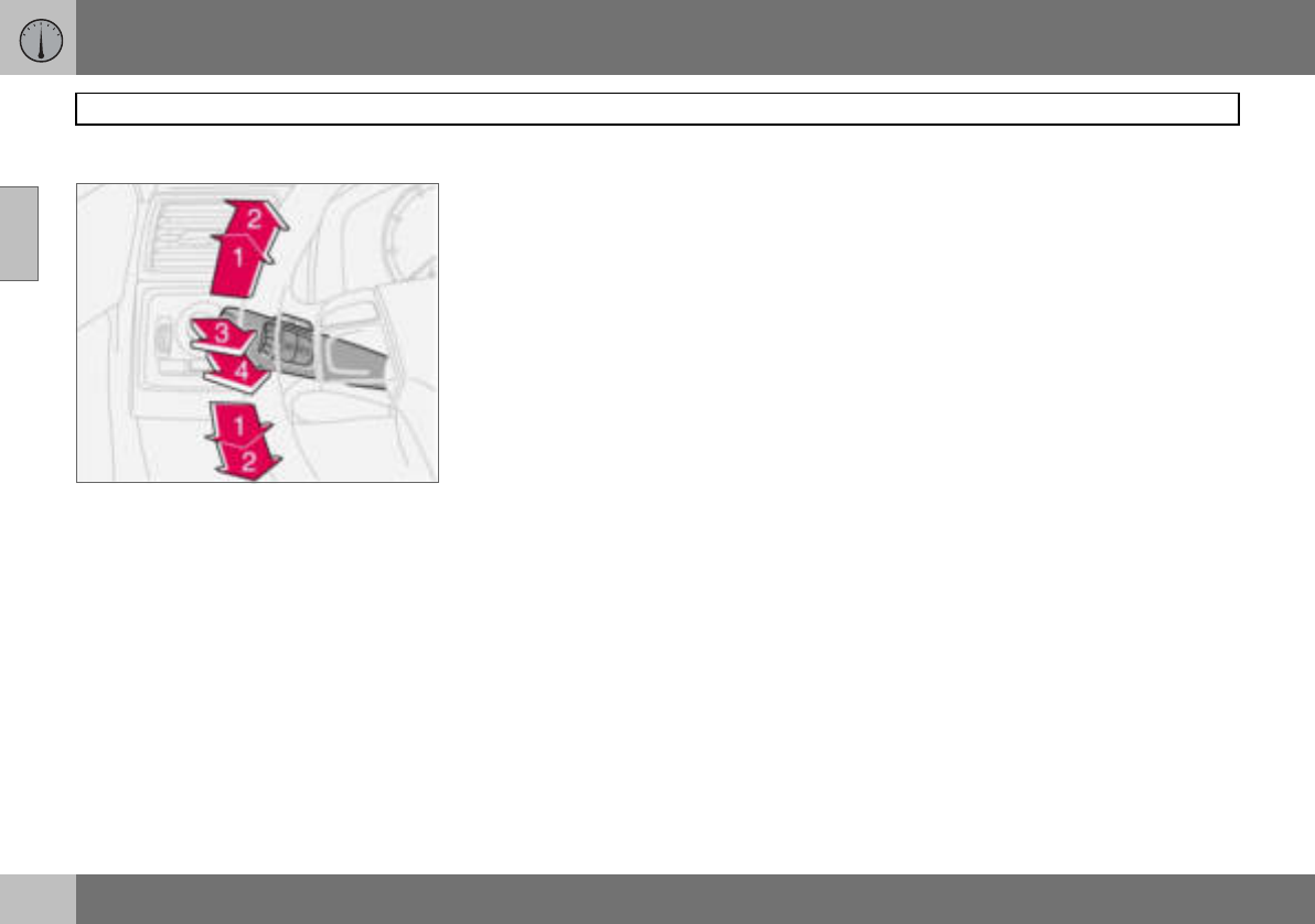
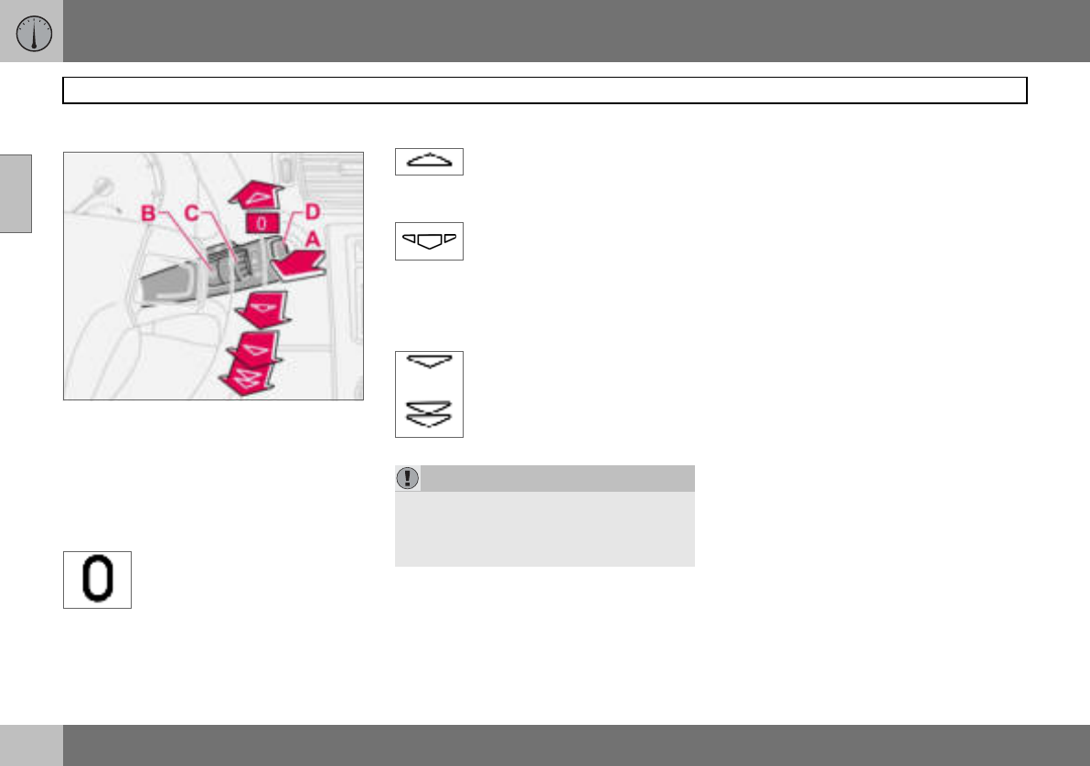
Windscreen wipers
A. Windscreen and headlamp washers
B. Rain sensor – On/Off
C. Thumbwheel
D. Wiper and washer, rear window
Windscreen wipers off
The windscreen wipers are off
when the stalk switch is in
position 0.
Single sweep
Raise the stalk switch to make a
single sweep.
Intermittent wiping
The delay between sweeps can
be adjusted. Turn the
thumbwheel (C) up for a shorter
interval between sweeps. Turn it down to in-
crease the delay.
Continuous wiping
The wipers sweep at normal
speed.
The wipers sweep at high
speed.
Windscreen/headlamp washers
Move the stalk switch toward the steering
wheel to start the windscreen and headlamp
washers. The wipers will make three more
sweeps once the stalk switch is released.
High-pressure headlamp washing
(option in certain markets)
High-pressure headlamp washing consumes
a large quantity of washer fluid. To save fluid,
the headlamps are washed as follows:
Dipped beam selected with the switch on
lighting panel:
The headlamps are washed the first time the
windscreen is washed. Within the next ten
minutes, they are washed every fifth wash
cycle of the windscreen. In the event of a
longer interval the headlamps are washed
each time.
Parking/position lamps selected with the
switch on the lighting panel:
• Bi-Xenon headlamps are only washed
every fifth wash cycle irrespective of the
time that elapses.
• Halogen headlamps are not washed.
The switch on the lighting panel is in
position 0:
• Bi-Xenon headlamps are only washed
every fifth wash cycle irrespective of the
time that elapses.
• Halogen headlamps are not washed.
IMPORTANT
Use plenty of washer fluid when the wipers
are cleaning the windscreen. The wind-
screen must be wet when the windscreen
wipers are operating.
02 Instruments and controls
51
Right-hand stalk switch
02
Wiper and washer, rear window
Press the stalk switch forward to initiate rear
window washing and wiping. The wiper blade
makes several sweeps once washing has fin-
ished. The control at the end of the stalk has
three positions:
Intermittent wiping:
– Depress the top of the switch.
Normal speed:
– Depress the bottom of the switch.
Neutral:
– Function deactivated.
Wiper – reversing
Engaging reverse gear while the windscreen
wipers are on initiates intermittent rear win-
dow wiping. If the rear window wiper is al-
ready on at normal speed, no change is
made.
The function for intermittent wiping for re-
verse can be deactivated. Contact an author-
ised Volvo workshop.
Rain sensor (option)
The rain sensor automatically activates the
windscreen wipers based on how much wa-
ter it detects on the windscreen. The sensitiv-
ity of the rain sensor can be adjusted using
the thumbwheel (C).
Turn the thumbwheel clockwise for higher
sensitivity and anticlockwise for lower sensi-
tivity. (An extra sweep is made when the
thumbwheel is turned clockwise.)
On/Off
When activating the rain sensor, the ignition
key must be in position I or II and the wind-
screen wiper stalk switch must be in
position 0.
Activating the rain sensor:
– Press the button (B). A display symbol
shows that the rain sensor is active.
To turn the rain sensor off, either:
– Press button (B)
– Press the stalk switch downward to anoth-
er wiper program. If the stalk switch is
raised, the rain sensor will remain active,
the wipers make an extra sweep and then
return to rain sensor mode when the stalk
is released to position 0.
The rain sensor is automatically deactivated
when the key is removed from the ignition
switch or five minutes after the ignition is
switched off.
Thumbwheel
Use the thumbwheel to adjust the frequency
of sweeps when intermittent wiping is select-
ed, or the sensitivity to rain when the rain
sensor is selected.
IMPORTANT
At an automatic car wash: Deactivate the
rain sensor by pressing the button (B) while
the ignition key is in position I or II. Other-
wise, the windscreen wipers could start
swiping and become damaged.
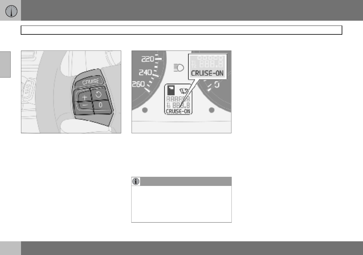
02 Instruments and controls
52
Cruise control (option)
02
Activating
The controls for cruise control are to the left
of the steering wheel.
Setting the desired speed:
–Press the CRUISE button. CRUISE is
shown on the combined instrument panel.
–Touch + or — to lock the vehicle speed.
CRUISE-ON appears on the combined
instrument panel.
Cruise control cannot be engaged at speeds
below 30 km/h or above 200 km/h.
Increasing or decreasing speed
– Increase or decrease the locked speed by
pressing and holding + or –. The speed of
the car when the button is released is set
as the new speed.
Pressing (less than half a second) + or –
changes the speed 1 km/h or 1.6 km/h1.
Temporary disengagement
– Press 0 to disengage the cruise control
temporarily. CRUISE will be shown on the
combined instrument panel. The speed
set earlier is stored in the memory.
The cruise control is also temporarily disen-
gaged when:
• the brake pedal or clutch pedal is de-
pressed
• speed falls below 25–30 km/h when trav-
elling uphill1
• the gear selector is moved to position N
• wheel spin or wheel lock-up occurs
• a temporary increase in speed lasts longer
than one minute.
NOTE
A temporary increase in speed (less than
one minute) using the accelerator, such as
while overtaking, does not affect the cruise
control setting. When you release the accel-
erator, the car will return to the pro-
grammed speed.
1Depending on engine type.
02 Instruments and controls
53
Cruise control (option)
02
Return to the set speed
–Press this button to resume
the previously set speed.
CRUISE-ON appears on the
combined instrument panel.
Disengaging
–Press CRUISE to disengage the cruise
control. CRUISE-ON goes out on the
combined instrument panel.
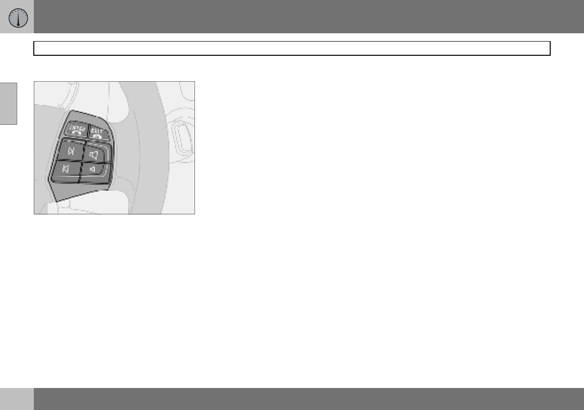
02 Instruments and controls
54
Steering wheel keypad (option)
02
The four buttons at the bottom of the steering
wheel keypad control the radio and the
phone. The function of a button depends on
which system is active. The steering wheel
keypad can be used to scroll between preset
stations, change CD tracks and adjust the
volume.
Press and hold one of the arrow keys to fast
forward/reverse or search for the next sta-
tion.
The phone must be switched on to adjust au-
dio system settings.
The phone must be activated with the
ENTER key to enable control of the phone
functions with the arrow keys.
To return to Audio only, press EXIT.
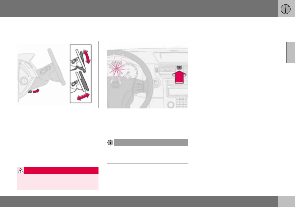
02 Instruments and controls
55
Steering wheel adjustment, hazard warning flashers
02
Steering wheel adjustment
The steering wheel can be adjusted for both
height and reach.
– Pull the lever towards you to release the
steering wheel.
– Adjust the steering wheel to the position
that suits you best.
– Push back the lever to fix the steering
wheel in place. If the lever is stiff, press the
steering wheel lightly at the same time as
you push the lever back.
Hazard warning flashers
Use the hazard warning flashers (all direction
indicators flash) when the car is stopped
where it could be a traffic hazard or obstruc-
tion. Press the button to activate the
function.
WARNING
Adjust the steering wheel before driving off,
never while driving. Before driving, check
that the steering wheel is fixed in position.
NOTE
Regulations regarding the use of hazard
warning flashers vary from country to coun-
try.
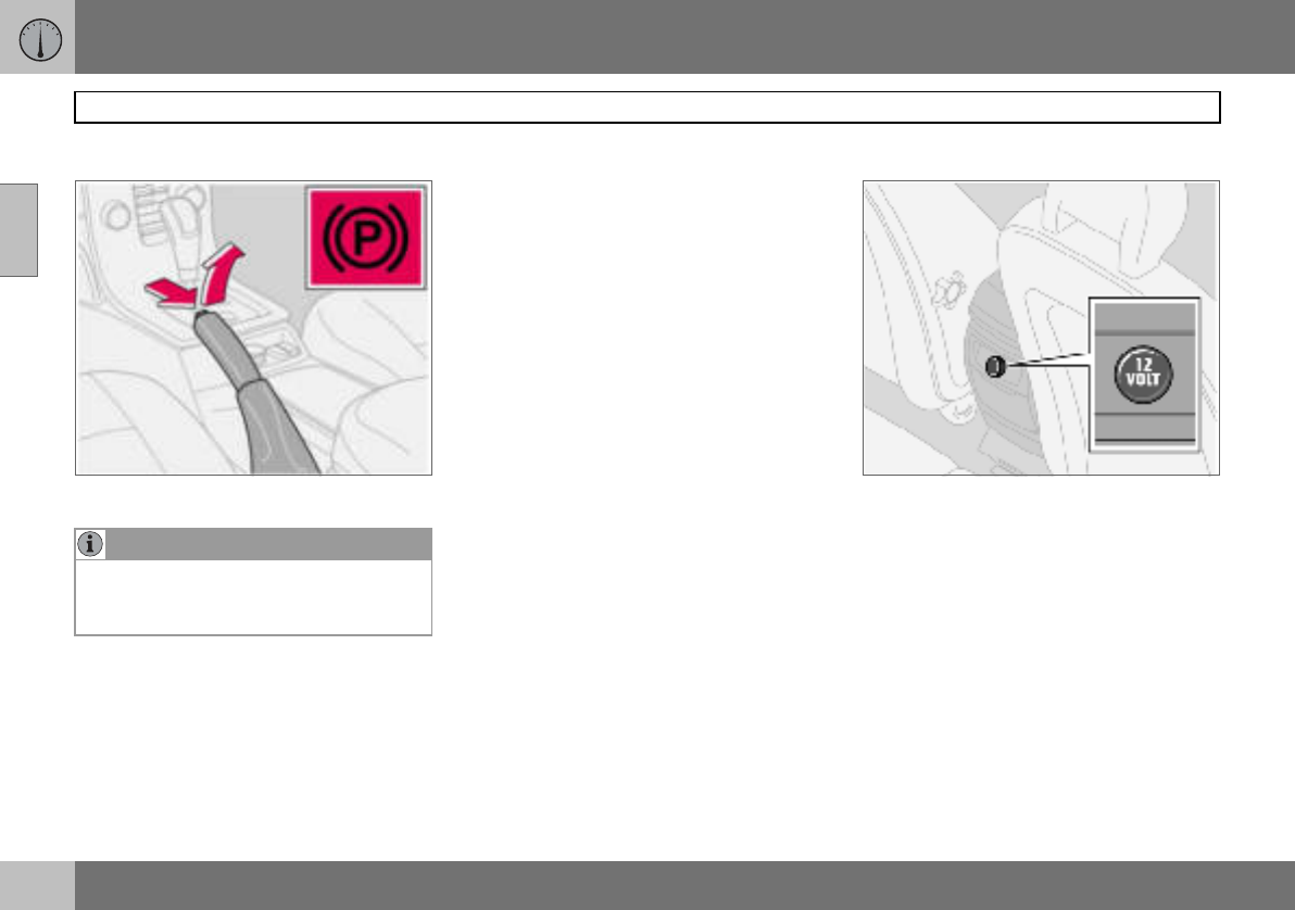
02 Instruments and controls
56
Parking brake, electrical socket
02
Parking brake (handbrake)
The lever is located between the front seats.
How to Apply the parking brake
– Press the foot brake pedal down firmly.
– Pull up the parking brake lever up firmly to
its full extent.
– Release the foot brake pedal and make
sure that the car is at a standstill position.
– If the vehicle rolls, the parking brake lever
must be pulled more firmly.
– When parking a vehicle always put the
gear selector in position 1 (for manual
transmission) or P (for automatic transmis-
sion).
Parking on a hill
If the car is parked facing uphill; turn the
wheels away from the kerb.
If the car is parked facing downhill; turn the
wheels toward the kerb.
How to release the parking brake
–Press the foot brake pedal down firmly.
– Pull the parking brake lever up slightly,
press the button, release the parking
brake lever and release the button.
Electrical socket in rear seat
The electrical socket can be used for various
accessories, such as a mobile phone or a
cooler box. It is designed for 12 V. The maxi-
mum current is 10 A. The ignition key must
be at least in position I so that the socket can
supply power.
Cigarette lighter (option)
Press in the lighter to activate it. The lighter
pops out again when it is ready. Pull it out
and light a cigarette on the heated coils.
NOTE
The warning lamp symbol in the combined
instrument panel comes on irrespective of
how hard the parking brake is applied.
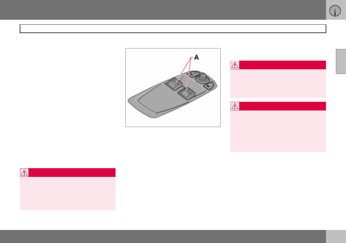
02 Instruments and controls
57
Power windows
02
Operating
The power windows are operated using the
controls in the doors. The ignition key must
be in position I or II for the power windows to
operate. The windows continue to work for a
limited time when the car is stopped and ig-
nition key removed, provided none of the
doors is opened. Operate the windows with
caution.
To open a window:
– Depress the front of the control.
To close a window:
– Raise the front of the control.
Remote control and lock buttons
To operate the power windows with lock but-
tons and remote control, see page 94
and page 101.
Driver’s door
A. Controls, power windows front
The driver can operate both power windows
from the driver’s seat.
The windows can be opened and closed in
two ways:
Manual operation
– Depress one of the controls (A) gently or
raise it gently. The power window opens
or closes as long as the switch is actuat-
ed.
Automatic operation
– Depress one of the controls (A) or raise it
fully, then release. The side window will
then open or close automatically. If the
window is obstructed by an object, the
movement will stop.
WARNING
Make sure that children and other passen-
gers cannot be trapped in any way when
closing the windows. Pay close attention if
the rear door windows are controlled from
the driver’s door or if the windows are
closed with the remote control.
WARNING
The function that interrupts the movement
of the windows in the event of blocking
works with both automatic and manual
closing, although not with pinch protection
deployed.
WARNING
If there are children in the car:
Remember to switch off the supply to the
power windows by removing the ignition
key if the driver leaves the car.
Make sure that children and other passen-
gers cannot be trapped in any way when
closing the windows.
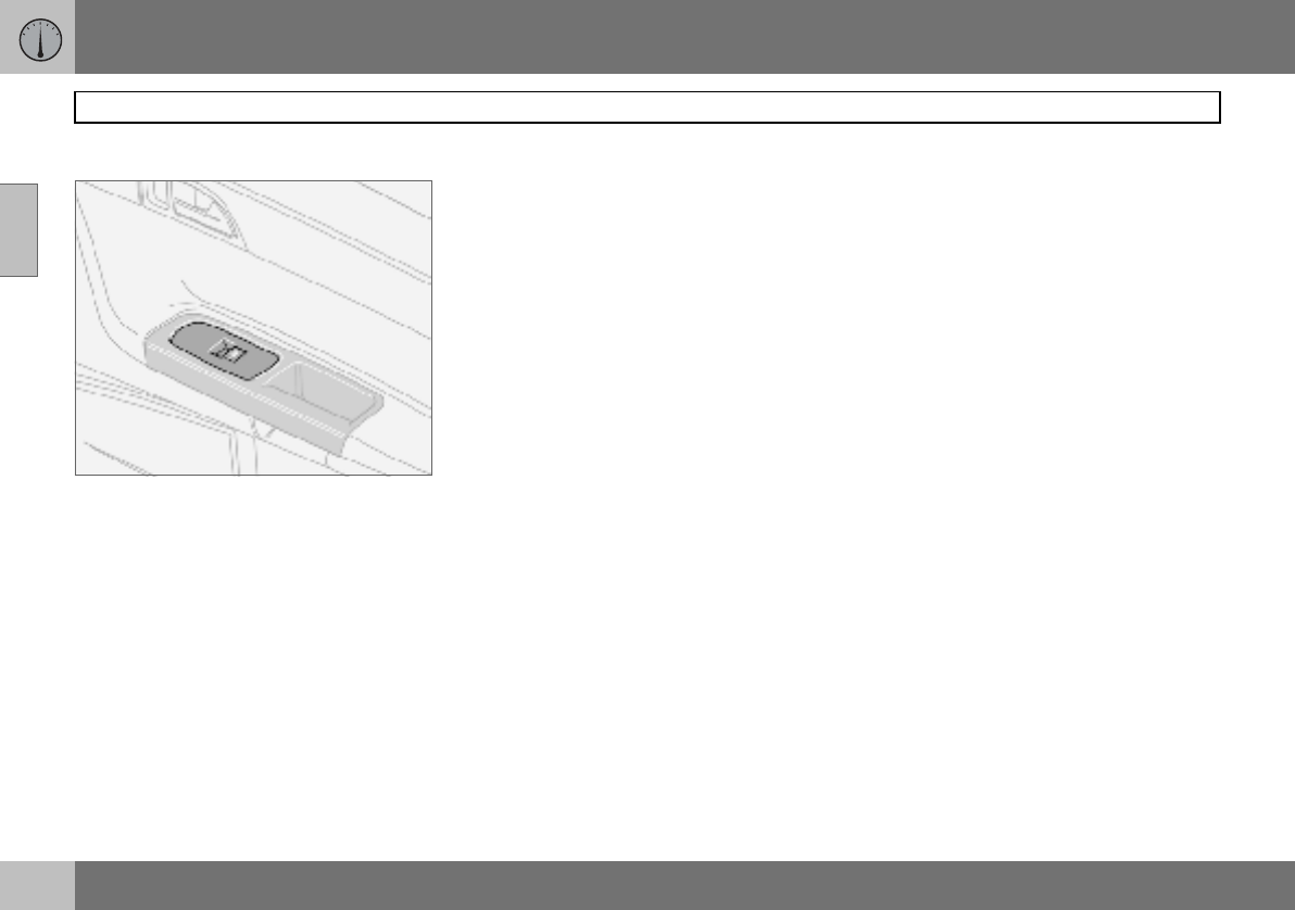
02 Instruments and controls
58
Power windows
02
Passenger seat
Passenger seat
The control in the front passenger door oper-
ates that window only.
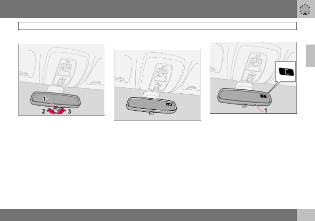
02 Instruments and controls
59
Rearview and door mirrors
02
Interior rearview mirror
Bright light from behind could be reflected in
the rearview mirror and dazzle the driver. Use
dimming when disturbed by light from be-
hind.
Dipping
1. Control for dimming
2. Normal position
3. Dimmed position.
Automatic dimming (option)
Bright light from behind is automatically
dimmed by the rearview mirror. The control
(1) is not available in mirrors with automatic
dimming.
Interior rearview mirror with compass
(option on certain markets)
The upper right-hand corner of the rearview
mirror has an integrated display that shows
the compass direction in which the front of
the car is pointing. Eight different directions
are shown with English abbreviations:
N (north), NE (north east), E (east), SE (south
east), S (south), SW (south west), W (west)
and NW (north west).
Calibrating the compass
The earth is divided into 15 magnetic zones.
The compass is set for the geographical area
to which the car was delivered. The compass
should be calibrated if the car is moved
across several magnetic zones.
– Stop the car in a wide open area with the
engine running at idling speed.
– Press and hold button (1) for at least
6 seconds. Following which, the
character C is shown (the button is con-
cealed so use a paper clip for example to
press it in).
– Press and hold button (1) for at least
3 seconds. The number for the current
magnetic zone is displayed.
02 Instruments and controls
60
Rearview and door mirrors
02
– Press the button (1) repeatedly until the
number for the required magnetic zone (1–
15 ) is shown, refer to the map of magnetic
zones for the compass.
– Wait until the display returns to showing
the character C.
– Following which, press and hold the but-
ton for 9 seconds and select L for left-
hand drive cars and R for right-hand drive.
Drive slowly in a circle with a maximum
speed of 10 km/h until a compass direction is
shown on the display, which indicates that
the calibration is complete.
Magnetic zones, Europe.
Magnetic zones, Asia.
Magnetic zones, South America.
Magnetic zones, Australia.
Magnetic zones, Africa.
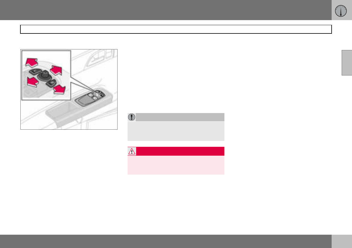
02 Instruments and controls
61
Rearview and door mirrors
02
Door mirrors
The controls for adjusting the two door mir-
rors are at the front of the driver’s door arm-
rest. The rearview mirrors can be operated in
ignition position I and II.
–Press the L button for the left-hand door
mirror or the R button for the right-hand
door mirror. The light on the button illumi-
nates.
– Adjust the position with the joystick in the
centre.
–Press the L or R button again. The lamp
goes out.
Retractable power door mirrors
(option)
The mirrors can be retracted for parking and
driving in narrow spaces. This can be done in
ignition position I and II.
Retracting the mirrors
–Press down the L and R buttons at the
same time.
– Release the buttons. The mirrors automat-
ically stop in the fully retracted position.
Folding out the mirrors
–Press down the L and R buttons at the
same time.
– Release the buttons. The mirrors automat-
ically stop in the fully extended position.
Resetting to neutral
Mirrors that have been moved out of position
by an external force must be reset to the neu-
tral position for the electrical retracting and
extending to work.
–Use the L and R buttons to retract the
mirrors.
– Extend them again with the L and R but-
tons. The mirrors are now reset in neutral
position.
Approach and home safe lighting
The lamp on the door mirrors (option) illumi-
nates when the approach lighting or home
safe lighting is activated.
Blind Spot Information System, BLIS
(option)
BLIS is an information system that under cer-
tain conditions can help to draw the driver’s
attention to vehicles moving in the same di-
rection in the so-called "blind spot", see
page 125.
IMPORTANT
Do not use a scraper to remove ice from the
mirrors as this can scratch the glass. Use
the defroster function instead, see page 71.
WARNING
The driver-side door mirror is wide angled
to provide optimal vision. Objects may ap-
pear further away than they actually are.
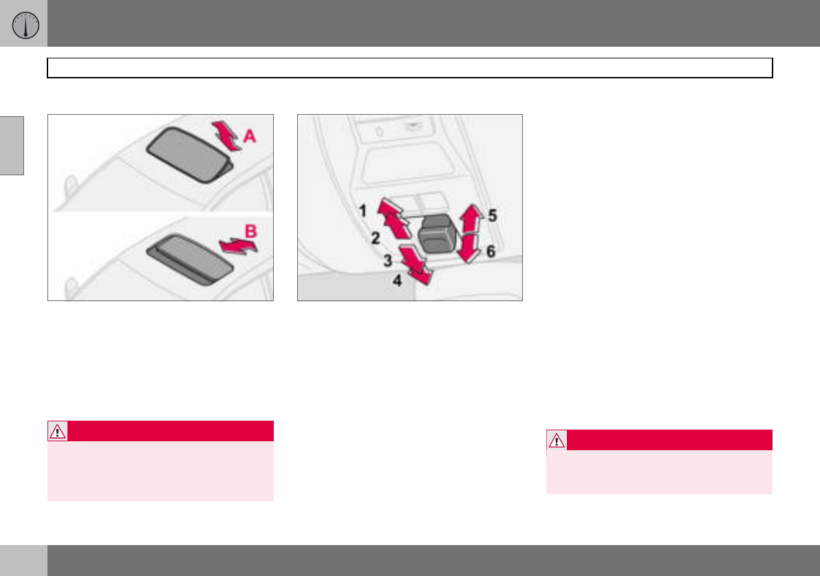
02 Instruments and controls
62
Power sunroof (option)
02
Open positions
The sunroof controls are located in the roof
panel. The sunroof can be opened in two po-
sitions:
A. Ventilation position, up at the rear edge
B. Sliding position, backwards/forwards
The ignition key must be in position I or II.
1. Opening, automatic
2. Opening, manual
3. Closing, manual
4. Closing, automatic
5. Opening, ventilation position
6. Closing, ventilation position
Ventilation position
To open:
– Press the rear edge of the control (5) up-
ward.
To close:
– Pull the rear edge of the control (6) down-
ward.
From ventilation position to fully open sun-
roof:
– Pull the control rearward to the end
position (1) and release.
Sliding position
Automatic operation
– Pull the control past the point of
resistance (2) to the rear end position (1)
or past the point of resistance (3) to the
forward end position (4) and release. The
sunroof opens/closes completely.
Manual operation
To open:
– Pull the control rearward to the point of
resistance (2). The sunroof moves toward
the fully open position as long as the
button is held in this position.
To close:
– Press the control forward to the point of
resistance (3). The sunroof moves toward
the closed position as long as the button
is held in this position.
WARNING
If there are children in the car:
Switch off the supply to the power sunroof
by removing the ignition key if the driver
leaves the car.
WARNING
The sunroof’s pinch-protection function
only operates during automatic closing, not
manual.
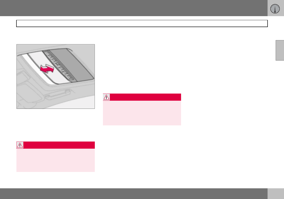
02 Instruments and controls
63
Power sunroof (option)
02
Closing with remote control or lock
button
– Press and hold the lock button for two
seconds. The sunroof and windows close.
The doors lock.
If closing needs to be interrupted:
– Press the lock button again.
Sunscreen
The sunroof features a manual, sliding interi-
or sunscreen. The sunscreen slides back au-
tomatically when the sunroof is opened. Grip
the handle and slide the screen forward to
close it.
Pinch protection
The sunroof’s pinch protection function is
activated if the hatch is blocked by an object.
If blocked, the sunroof will stop and automat-
ically open to the previous position.
WARNING
Make sure that children or other passengers
are not in danger of having hands trapped
when closing the sunroof with the remote
control. Always operate the sunroof with
caution.
WARNING
The sunroof’s pinch-protection function
only operates during automatic closing, not
manual.
Make sure children’s hands are clear when
closing the sunroof.
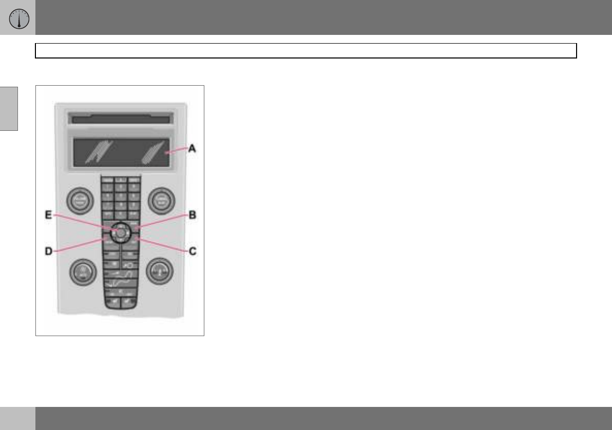
02 Instruments and controls
64
Personal preferences
02
Control panel.
Possible settings
Personal preferences can be set for some of
the car’s functions. This applies to locks, cli-
mate control and audio functions. For audio
functions, see page 196.
Control panel
A. Display
B. MENU
C. EXIT
D. ENTER
E. Navigation
Use
The settings are shown on the display (A).
Open the menu to enter settings:
– Press MENU (B).
– Scroll, for example, to Car Settings with
the navigation button (E).
– Press ENTER (D).
– Select an alternative with the navigation
button (E).
– Press ENTER to activate the selection.
Close the menu:
– Press EXIT (C) for approximately one sec-
ond.
Climate control settings
Auto blower adjust
The fan speed can be set to AUTO mode in
cars equipped with ECC:
– Select from Low, Normal and High.
Recirculation timer
When the timer is active, the air recirculates
for 3 – 12 minutes, depending on the outside
air temperature.
– Select On/Off depending on whether or
not you wish the recirculation timer to be
active.
Reset all
Resets the climate function options to the
factory settings.
Car settings
Unlock feedback light
The hazard warning flashers can provide
feedback when the car is unlocked with the
remote control. This function can be turned
On/Off.
Lock feedback light
The hazard warning flashers can provide
feedback when the car is locked with the re-
mote control. This function can be turned
On/Off.

02 Instruments and controls
65
Personal preferences
02
Automatic locking – doors
When the speed of the car exceeds 7 km/h
the doors and tailgate can be locked auto-
matically. This function can be turned On/
Off.
Unlock doors
There are two alternatives for unlocking:
•All doors – one press of the remote con-
trol unlocks both doors and the tailgate.
•Driver’s door first, then all others – one
press of the remote control unlocks the
driver’s door. A second press then un-
locks the passenger door and the tailgate.
Keyless entry
•All doors – both doors and the tailgate are
unlocked at the same time.
•One front door – either of the front doors
or the tailgate can be unlocked separately.
Approach lighting
Select the time the car’s lights should remain
on when the approach lighting button is
pressed. The following alternatives are avail-
able: 30/60/90 seconds.
Home safe lighting
Select the time the car’s lights should remain
on when the left-hand stalk switch is pulled
back after the ignition key has been re-
moved. The following alternatives are availa-
ble: 30/60/90 seconds.
Information
•VIN number (Vehicle Identification
Number). The car’s unique identity
number.
•Number of keys. The number of keys
registered for the car is shown.

66
General information on climate control ....................................................68
Manual climate control, A/C .....................................................................70
Electronic climate control, ECC (option) ..................................................72
Air distribution ..........................................................................................75
Fuel-driven heater (option) ....................................................................... 76
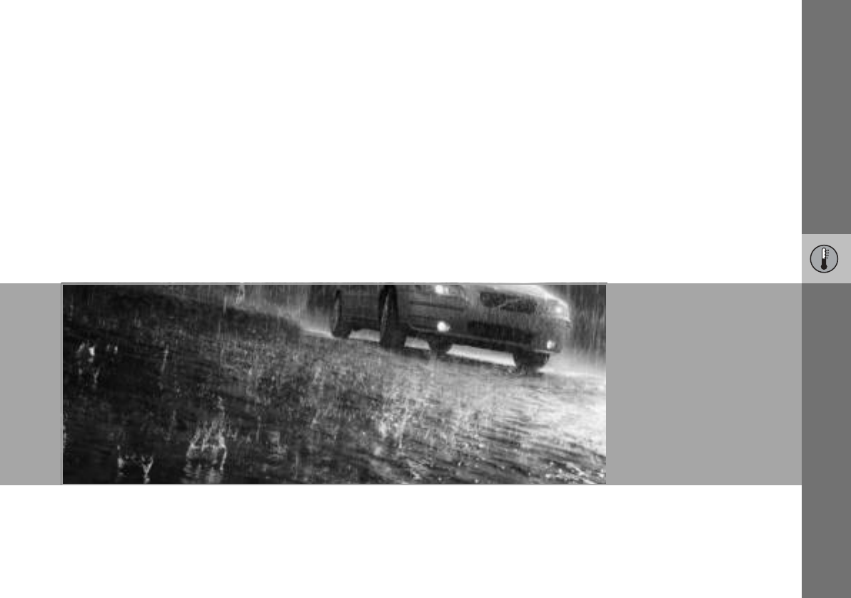
03
CLIMATE CONTROL
03 Climate control
68
General information on climate control
03
Air conditioning
The climate control system cools or heats as
well as dehumidifies the air in the passenger
compartment. The car is equipped with ei-
ther manual (A/C ) or electronic climate con-
trol (ECC).
Misting windows
Reduce the problem of windows misting up
on the inside by cleaning the windows. Use a
regular window cleaner.
Ice and snow
Remove ice and snow from the climate con-
trol system air intake (the grille between the
bonnet and the windscreen).
Fault tracing and repair
Entrust fault tracing and repair of the climate
control system to an authorised Volvo work-
shop only.
Refrigerant
The air conditioning system contains R134a
refrigerant. This refrigerant contains no chlo-
rine, which means that it is harmless to the
ozone layer. The system must only be
charged with R134a refrigerant. Have an au-
thorised Volvo workshop carry out this work.
Passenger compartment filter
All air entering the car’s passenger compart-
ment is only cleaned with one filter. This must
be replaced at regular intervals. Follow the
Volvo Service Programme for the recom-
mended replacement intervals. If the car is
used in a severely contaminated environ-
ment, it may be necessary to replace the filter
more often.
Display
There is a display above the climate control
panel. This displays climate control settings.
Personal preferences
You can set preferences for two climate con-
trol functions:
• Fan speed in AUTO mode (applies only to
cars with ECC).
• Recirculation timer for passenger com-
partment air.
For information about these settings, see
page 64.
NOTE
The air conditioning can be switched off,
but to ensure the best possible air in the
passenger compartment and prevent the
windows from misting, it should always
be on.
NOTE
There are different types of passenger com-
partment filter. Make sure that the correct
filter is fitted.
03 Climate control
69
General information on climate control
03
Air vents in the dashboard
A. Open
B. Closed
C. Lateral airflow
D. Vertical airflow
Aim the outer vents towards the side win-
dows to remove misting from the front side
windows.
Cold weather: Close the centre vents for op-
timum comfort and best demisting.
ECC (option)
Actual temperature
The temperature you select corresponds to
the physical experience with reference to
factors such as air speed, humidity and solar
radiation in and around the car.
Sensor location:
• The sun sensor is on the top side of the
dashboard.
• The temperature sensor for the passenger
compartment is behind the climate control
panel.
Side windows and sunroof
To ensure that the air conditioning works sat-
isfactorily, the side windows, and sunroof if
appropriate, should be closed.
Acceleration
The air conditioning system switches off
temporarily at full throttle. You may briefly
feel a temporary rise in temperature.
Condensation
In warm weather, condensation from the air
conditioning may drip under the car. This is
normal.
NOTE
Do not cover or block the sensors with
clothing or other objects.
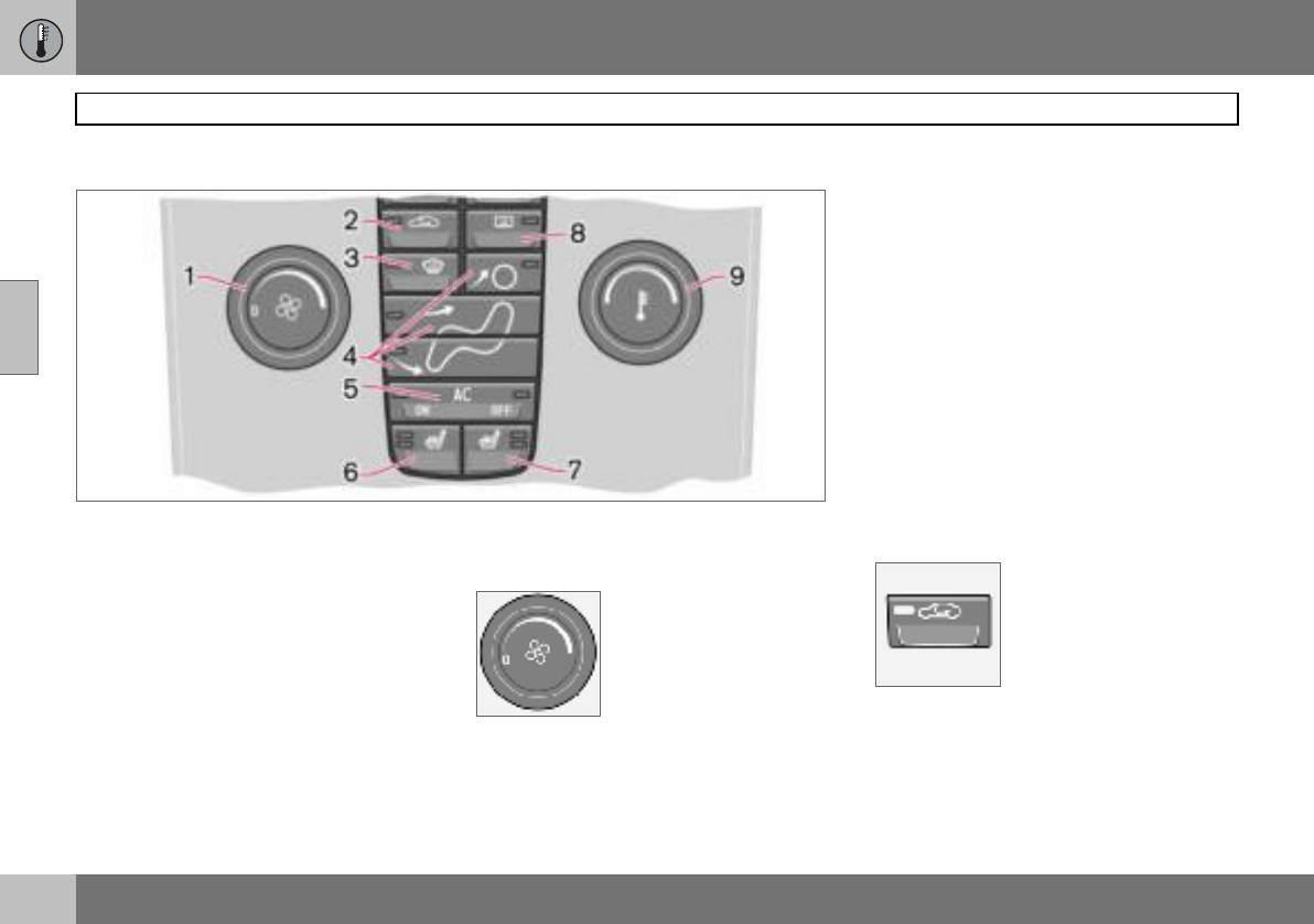
03 Climate control
70
Manual climate control, A/C
03
Control panel
1. Fan
2. Recirculation
3. Defroster
4. Air distribution
5. A/C – On/Off (ON/OFF)
6. Heated front left seat
7. Heated front right seat
8. Rear window and door mirror
defrosters
9. Temperature
Functions
1. Fan
Increase or decrease the
fan speed by turning the
knob.
If the knob is turned anti-
clockwise and the fan indi-
cator in the display goes
out, the fan and the air conditioning are
switched off. The display shows the fan sym-
bol and OFF.
2. Recirculation
Recirculation can be used
to shut out bad air, exhaust
fumes, etc. from the pas-
senger compartment. The
air in the passenger com-
partment is recirculated. No
outside air is taken into the
car. Recirculation (together with the air con-
ditioning system) cools the passenger com-
partment more quickly in hot weather. If the
air in the car recirculates for too long then
there is a risk of the windows misting.
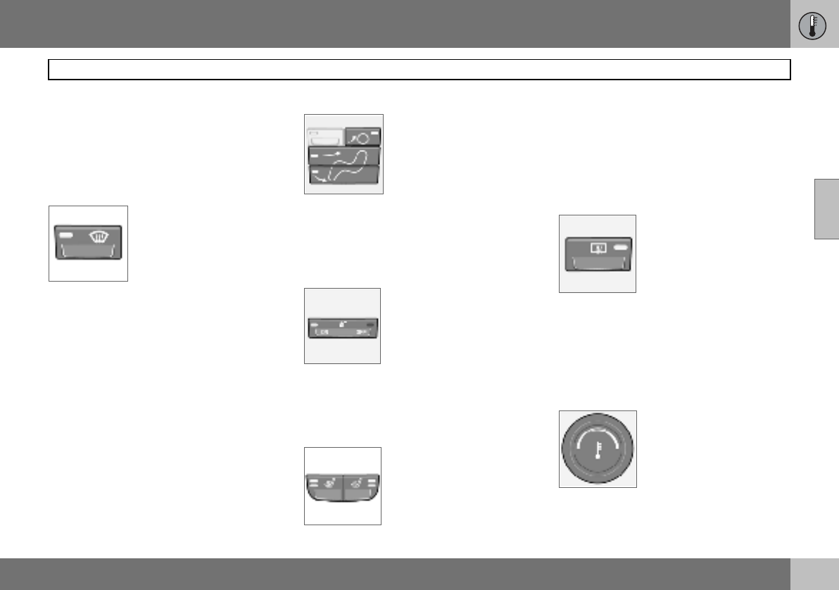
03 Climate control
71
Manual climate control, A/C
03
Timer
The timer function reduces the risk of icing,
misting and bad air (if recirculation is select-
ed). See page 64, for how to activate/deacti-
vate the function. When the Defroster (3) pro-
gram is selected, recirculation is deactivated.
3. Defroster
Used to quickly remove
misting and ice from the
windscreen and side win-
dows. Air flows to the win-
dows at high fan speed.
The light in the defroster
button illuminates when the
function is active.
The following also takes place when the de-
froster function is activated in order to pro-
vide maximum dehumidification in the pas-
senger compartment:
• the air conditioning (A/C) is automatically
switched on (can be switched off with the
A/C button (5)
• recirculation is automatically disengaged.
When the defroster function is switched off
the climate control system returns to the pre-
vious settings.
4. Air distribution
The airflow can be distribut-
ed to the windows, dash-
board vents or floor by
pressing the air distribution
buttons.
A symbol on the display
above the climate control panel and an illumi-
nated light in the button indicate which func-
tion has been selected.
Refer to the table on page 75.
5. A/C – On/Off
ON: Air conditioning is on. It
is controlled by the system’s
AUTO function. This way, in-
coming air is cooled and de-
humidified.
OFF: Air conditioning is off.
When the defroster function is activated the
air conditioning is automatically switched on
(can be switched off with the A/C button).
6. and 7. Heated front seats
(option in certain markets)
– Higher heat
Press the button once, both
lights illuminate.
–Lower heat
Press the button twice, one light illumi-
nates.
–Heat off
Press the button three times, light not
illuminated.
8. Rear window and door mirror
defrosters
Heating is used to quickly
remove misting and ice from
the rear window and door
mirrors.
Press the switch once to
start simultaneous rear win-
dow and rearview mirror defrosting. The
function is active if one light is illuminated in
the switch. The rearview mirror heating is de-
activated automatically after approximately
6 minutes. The rear window heating is deac-
tivated after approximately 12 minutes.
9. Temperature
Select cooling or heating for
both driver and passenger
side.
03 Climate control
72
Electronic climate control, ECC (option)
03
Control panel
1. AUTO
2. Fan
3. Recirculation/Air quality system
4. Defroster
5. Air distribution
6. A/C – On/Off (ON/OFF)
7. Heated front left seat
8. Heated front right seat
9. Rear window and door mirror
defrosters
10.Temperature selector
Functions
1. AUTO
The AUTO function auto-
matically regulates climate
control and maintains the
selected temperature. The
AUTO function controls
heating, air conditioning, fan
speed, recirculation, and air
distribution. If you select one or more manual
functions, the other functions continue to be
controlled automatically. All manual settings
are switched off when AUTO is switched on.
The display shows AUTO CLIMATE.
2. Fan
Turn the knob to increase or
decrease fan speed. If
AUTO is selected then fan
speed is regulated automat-
ically. The previously set fan
speed is disengaged.
03 Climate control
73
Electronic climate control, ECC (option)
03
3. Recirculation
The function is selected to
shut out bad air, exhaust
gases etc. from the passen-
ger compartment. The air in
the passenger compart-
ment is recirculated, i.e. no
outside air is taken into the
car when this function is activated. If the air
in the car recirculates for too long, there is a
risk of misting on the insides of the windows.
Timer
The timer function reduces the risk of icing,
misting and bad air (if recirculation is select-
ed). See Personal preferences, page 64, for
how to activate/deactivate the function.
3. Air quality system (option)
(same button as recircula-
tion)
The air quality system con-
sists of a multi-filter and a
sensor. The filter separates
gases and particles to re-
duce the levels of odours and pollution in the
passenger compartment. When the sensor
detects polluted outside air, the air intakes
are closed and the air in the passenger com-
partment is recirculated. A green light (A) illu-
minates in the button when the air quality
sensor is active.
Activating the air quality sensor:
– Press AUTO (1) to activate the air quality
sensor (normal setting).
Or:
– Switch between three functions by press-
ing the recirculation button repeatedly.
• Air quality sensor engaged – the light (A)
illuminates.
• No recirculation engaged, provided it is
not required for cooling in hot weather –
light not illuminated.
• Recirculation engaged – the light (M) illu-
minates.
Keep the following in mind:
• As a rule, the air quality sensor should
always be engaged.
• Recirculation is limited in cold weather to
avoid misting.
• If the insides of the windows start misting
up, disengage the air quality sensor.
• The defroster function for the front, side
and rear windows can also be used to
demist the windows.
4. Defroster
Used to quickly remove
misting and ice from the
windscreen and side win-
dows. Air flows to the win-
dows at high fan speed.
The light in the defroster
button illuminates when the
function is active.
The following also takes place when the de-
froster function is activated in order to pro-
vide maximum dehumidification in the pas-
senger compartment:
• the air conditioning (A/C) is automatically
switched on (can be switched off with the
A/C button (6)
• recirculation is automatically disengaged.
When the defroster function is switched off
the climate control system returns to the pre-
vious settings.
NOTE
If the knob is turned anticlockwise and the
fan indicator in the display goes out, the fan
and the air conditioning are switched off.
The display shows the fan symbol and OFF.
NOTE
When Defroster (4) is selected, recirculation
is always deactivated.
03 Climate control
74
Electronic climate control, ECC (option)
03
5. Air distribution
The airflow can be distribut-
ed to the windows, dash-
board vents or floor by
pressing the air distribution
buttons.
A symbol on the display
above the climate control panel and an illumi-
nated light in the button indicate which func-
tion has been selected.
Refer to the table on page 75.
6. A/C – On/Off (ON/OFF)
ON: Air conditioning is on. It
is controlled by the sys-
tem’s AUTO function. This
way, incoming air is cooled
and dehumidified.
OFF: Air conditioning is off.
When the defroster function is activated the
air conditioning is automatically switched on
(can be switched off with the A/C button).
7. and 8. Heated front seats
(option in certain markets)
To activate front seat heat-
ing:
– Higher heat:
Press the button once – both lights illumi-
nate.
– Lower heat:
Press the button twice – one light illumi-
nates.
–Heat off:
Press the button three times – light not
illuminated.
9. Rear window and door mirror
defrosters
Heating is used to quickly
remove misting and ice from
the rear window and door
mirrors.
Press the switch once to
start simultaneous rear win-
dow and rearview mirror defrosting. The
function is active if one light is illuminated in
the switch. The rearview mirror heating is de-
activated automatically after approximately
6 minutes. The rear window heating is deac-
tivated after approximately 12 minutes.
10. Temperature selector
The temperatures on the
driver and passenger sides
can be set independently.
Press the button once to
activate one side only.
Press again to activate the
other side. Press the button a third time to
activate both sides.
The active side is indicated by the button’s
light and on the display above the climate
control panel.
When the car is started, the most recent set-
ting is resumed.
NOTE
Heating or cooling cannot be hastened by
selecting a higher or lower temperature than
the actual desired temperature.
03 Climate control
75
Air distribution
03
Air distribution Use: Air distribution Use:
Air to windows. Some air
flows from the air vents.
The air is not recirculated.
Air conditioning is always
engaged.
To remove ice and
misting quickly. Air to the floor and
windows. Some air flows
from the dashboard air
vents.
To ensure comfortable
conditions and good
demisting in cold or
humid weather.
Air to windscreen and side
windows. Some air flows
from the air vents.
To prevent misting and
icing in a cold and
humid climate. (Not for
low fan speed.)
Air to floor and from
dashboard air vents. In sunny weather with
cool outside tempera-
tures.
Airflow to windows and
from dashboard air vents. To ensure good
comfort in warm, dry
weather.
Air to floor. Some air flows
to the dashboard air vents
and windows.
To w a r m t h e fe e t .
Airflow to the head and
chest from the dashboard
air vents.
To ensure efficient
cooling in warm
weather.
Airflow to windows, from
dashboard air vents and to
the floor.
To cool the feet or
provide warmer air to
the upper body in cold
weather or hot, dry
weather.
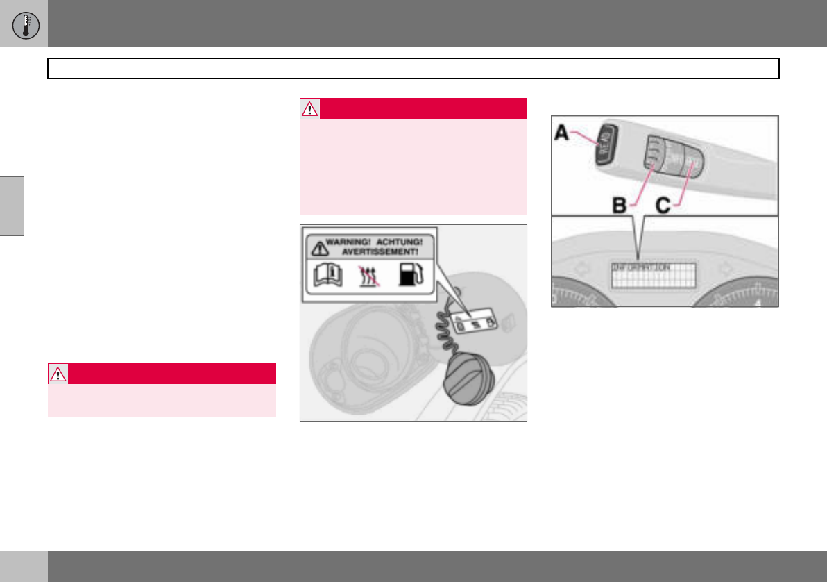
03 Climate control
76
Fuel-driven heater (option)
03
General information about heaters
The parking heater can be started immedi-
ately or set with two different start times us-
ing TIMER 1 and TIMER 2. Here, start time
refers to the time the car is heated and ready.
The car’s electronic system calculates when
heating should be started based on the out-
side temperature. The heater is not run if the
outdoor temperature exceeds 25 C. At tem-
peratures of –10 C and below, the maximum
running time of the parking heater is
60 minutes.
Parking on a hill
If the car is parked on a steep hill, the front of
the car should point downhill to ensure that
there is a supply of fuel to the parking
heater.
Warning decal on fuel filler flap.
Activating the heater
– Enter the time when the car is to be used.
Press RESET (C) to enter the hours and
minutes.
– Press and hold the RESET (C) button until
the timer is activated.
Direct start
– Use the thumbwheel (B) to scroll to
DIRECT START.
– Press RESET (C) to access the options
ON and OFF.
– Select ON. The heater will now run for
60 minutes. Heating of the passenger
compartment will begin as soon as the
engine coolant has reached a temperature
of 30 ºC.
WARNING
The car must be outdoors when the petrol
or diesel heater is used.
WARNING
Switch off the fuel-driven heater before
starting to refuel. Fuel which spills onto the
ground can be ignited.
Check the information display to see that
the heater is switched off. When the parking
heater is running, PARK HEAT ON is
shown on the information display.
03 Climate control
77
Fuel-driven heater (option)
03
Immediate stop of heater
– Use the thumbwheel (B) to scroll to
DIRECT START.
–Press RESET (C) to access the options
ON and OFF.
–Select
OFF.
Battery and fuel
If the battery has insufficient charge or the
fuel level is too low, the parking heater will be
switched off automatically. A message ap-
pears on the information display. Acknowl-
edge the message by pressing READ (A).
Setting the TIMER 1 and 2
For safety reasons, you can only programme
times for the following 24 hours, not several
days in advance.
– Scroll with the thumbwheel to TIMER.
–Touch RESET to move to the flashing
hours setting.
– Scroll with the thumbwheel to the desired
hour.
–Touch RESET to move to the flashing
minutes setting.
– Scroll with the thumbwheel to the desired
minute.
–Touch RESET to confirm the setting.
– Press RESET to activate the timer. After
setting TIMER 1 a second start time can
be programmed with TIMER 2. Access
this with the thumbwheel. Set the alterna-
tive start time in the same way as
TIMER 1.
Messages on the display
When TIMER 1, TIMER 2 and DIRECT
START are activated, the information symbol
on the combined instrument panel illumi-
nates and an explanatory text appears on the
information display. The display also indi-
cates which TIMER is active when the driver
removes the key from the ignition to leave the
car.
Clock/timer
If the car clock is reset after the heater timers
are programmed, the selected times will be
cancelled.
Additional heater (diesel)
(certain countries)
Extra heat from the additional heater may be
required in cold weather to reach the correct
temperature in the passenger compartment.
The additional heater starts automatically
when extra heat is required if the engine is
running. It is switched off automatically when
the correct temperature is reached or when
the engine is switched off.
NOTE
The car can be started and driven while the
parking heater is still running.
IMPORTANT
Repeated use of the parking heater com-
bined with short journeys may discharge
the battery and impair starting. If the heater
is used regularly, the car must be driven for
the same time as the heater is run to ensure
that the alternator has time to charge the
battery.

78
Front seats ...............................................................................................80
Interior lighting .........................................................................................82
Storage spaces in the passenger compartment ......................................84
Rear seat ..................................................................................................86
Cargo area ................................................................................................87
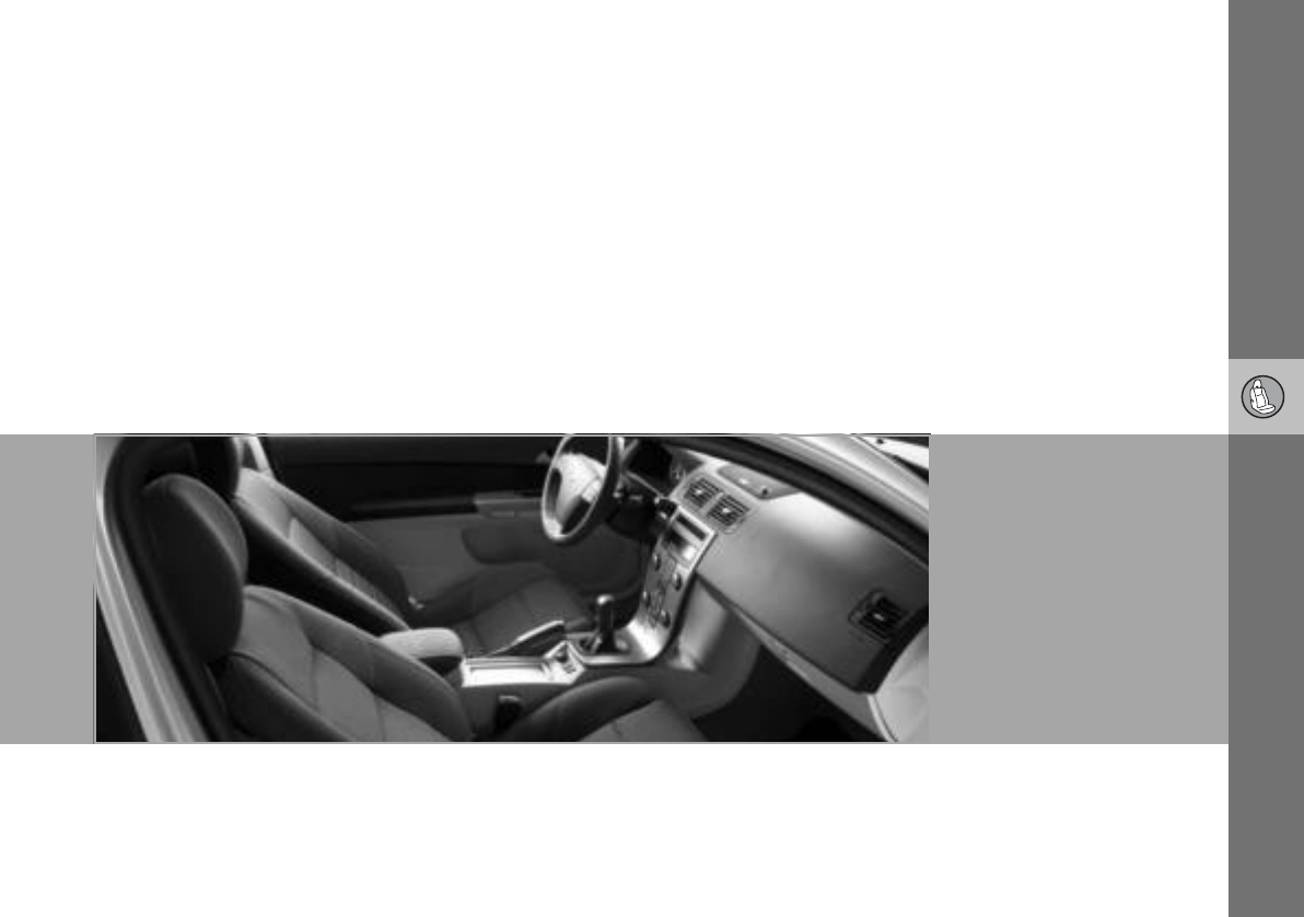
04
INTERIOR
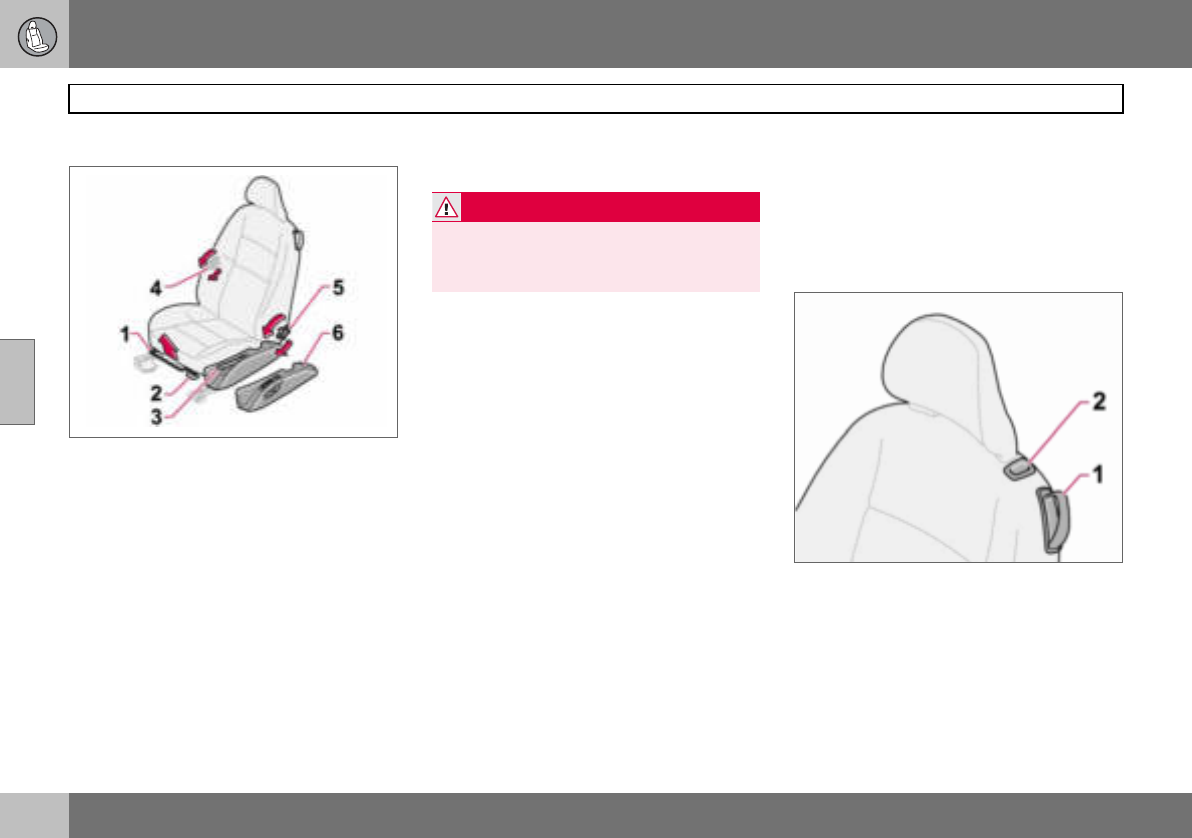
04 Interior
80
Front seats
04
Seating position
The driver’s and passenger seats can be ad-
justed to the optimum sitting and driving po-
sitions.
1. Forward/backward: lift the handle to ad-
just the distance to the steering wheel
and pedals. Check that the seat is locked
after changing position.
2. Raise/lower front edge of seat cushion,
pump up/down.
3. Raise/lower the seat, pump up/down.
4. Lumbar support1, turn the wheel.
5. Adjust backrest rake, turn the wheel.
6. Control panel for power seat (option).
The lever (2) is not available for all seat mod-
els.
Entry to the rear seat – Easy entry
Make sure that the seatbelt is removed from
the belt guide before passengers enter or exit
the car, see page 14. The easy entry position
is intended for use when the seat is empty.
Mechanical seat
Move the seat forward:
– Move the handle (1) up to release the
backrest.
– Fold the backrest forward until it locks.
– Release the handle and slide the seat
forwards.
Move the seat backward:
– Move the seat backward to the original
position.
– Move the handle (1) up to fold the back-
rest back.
The seat returns to the same position it had
before folding forward for easy entry.
Power seat
Move the seat forward:
– Move the handle (1) up to release the
backrest.
– Fold the backrest forward until it locks.
– Press the button (2) located beside the
head restraint. Keep it depressed.
Easy entry
Move the seat backward:
– Press the button (2) located to the side of
the head restraint. Keep it depressed.
– Move the handle (1) up and fold back the
backrest.
1Also applies to power seat.
WARNING
Adjust the position of the driver’s seat be-
fore setting off, never while driving.
Check that the seat is locked in position.
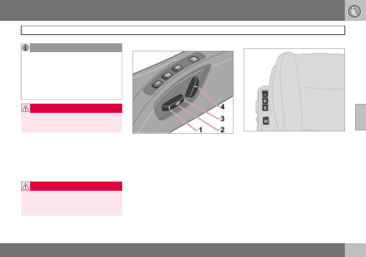
04 Interior
81
Front seats
04
The belt on the front passenger side must be
in the belt guide during driving, even when
there is no passenger sitting in the seat.
Floor mats (option)
Volvo supplies floor mats which are especial-
ly produced for your car.
Power seat (option)
The seats can be adjusted for a certain time
after unlocking the door with the remote con-
trol without the key being inserted into the ig-
nition switch. The seat can always be adjust-
ed in ignition position I or II.
1. Front edge of seat cushion up/down
2. Seat, forwards/backwards
3. Seat, up/down
4. Backrest rake
An overload protection is deployed if one of
the seats is blocked. If this happens, turn off
the ignition and wait a short time before ad-
justing the seat again. Only one of the seat’s
settings can be adjusted at a time.
Memory function
Buttons for memory function
Store setting
– Adjust seat.
– Press and hold button M while pressing
button 1, 2 or 3 simultaneously.
Using a stored setting
Press one of the memory buttons 1 – 3 until
the seat stops. If you release the button then
the movement of the seat will stop.
NOTE
The seat can only be moved to the very
front (+6 cm) to facilitate entry and exit to
and from the rear seat when the backrest
has been folded forward.
If the backrest is folded back when the seat
is in the front position then the seat auto-
matically moves back approx. 6 cm after a
few seconds.
WARNING
Check that the backrest is properly folded
back by pushing and pulling the head re-
straint.
WARNING
The floor mat at the driver’s seat must be
firmly fitted and secured in the attachment
clips to prevent it from being trapped
around and under the pedals.
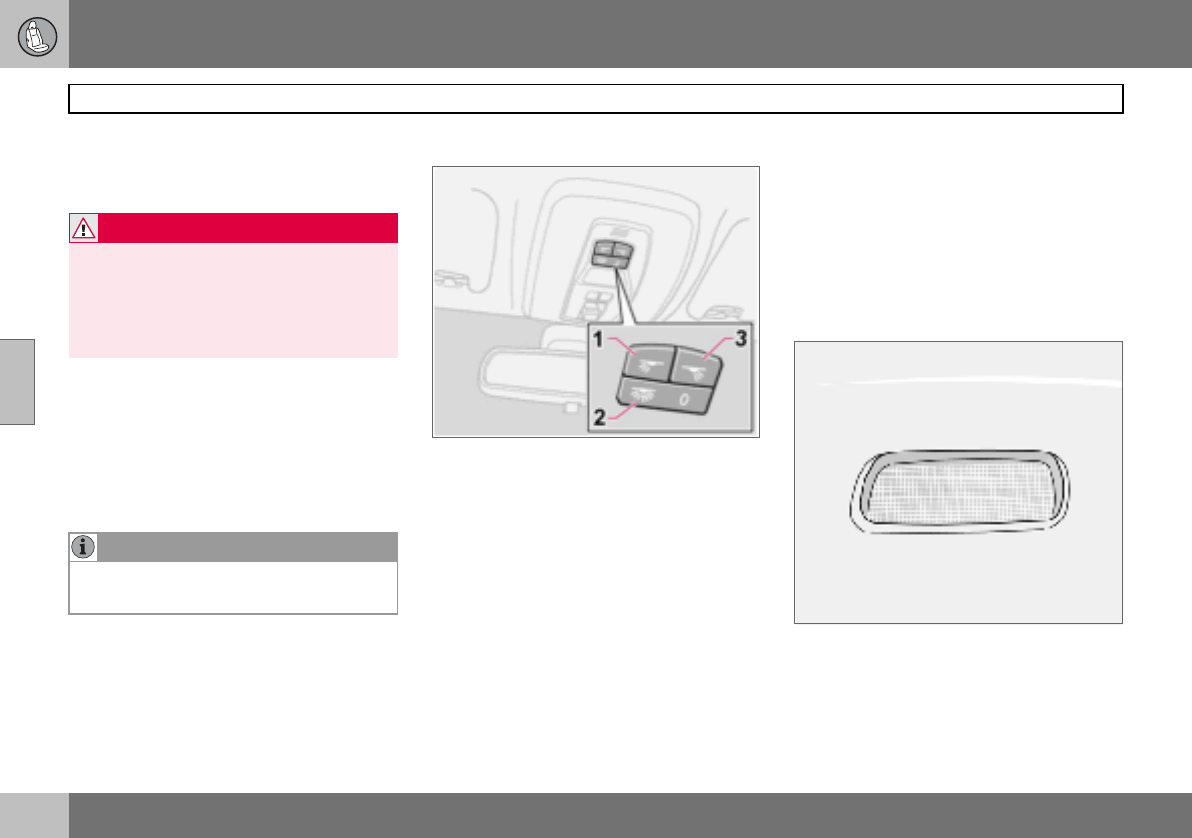
04 Interior
82
Interior lighting
04
Emergency stop
If the seat accidentally begins to move, press
any of the buttons to stop the function.
Key memory in remote control key
The driver’s seat settings are stored in the
key memory when the car has been locked
with the remote control key. When the car is
unlocked with the same remote control the
driver’s seat adopts the stored settings when
the driver’s door is opened.
Reading lamps and interior lighting
Passenger compartment lighting and reading
lamps.
1. Reading lamp left-hand, On/Off
2. Passenger compartment lighting front
and rear
3. Reading lamp right-hand, On/Off
Switch (2) has three positions for the interior
lighting:
• Off (0) – right-hand side depressed, auto-
matic lighting off.
• Neutral position – interior lighting comes
on when a door is opened and goes out
when the door is closed. The dimmer
function is active.
• On – left-hand side depressed, passenger
compartment lighting on.
The reading lamps can be switched on in ig-
nition position I and II as well as when the en-
gine is running. They can also be activated
within 30 minutes after the engine has been
switched off or when one of the doors has
been opened/closed.
Cargo area lighting
Interior lighting in rear seat and cargo area.
Cargo area lighting includes a further lamp
on the left-hand side of the cargo area.
WARNING
Risk of crushing. Make sure that children do
not play with the controls.
Check that there are no objects in front of,
behind or under the seat during adjustment.
Ensure that none of the rear seat passen-
gers can be trapped.
NOTE
The key memory is independent of the seat
memory.
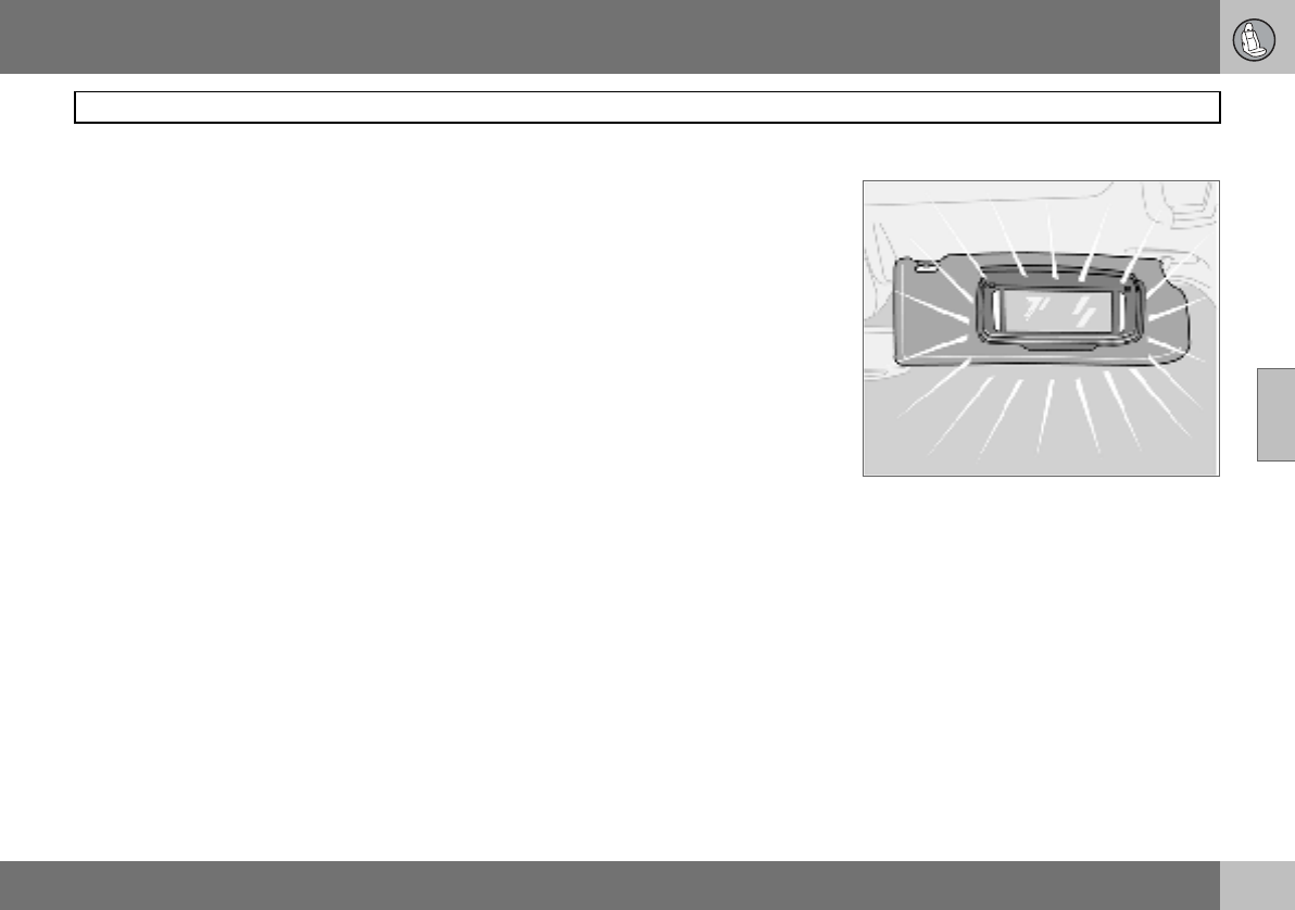
04 Interior
83
Interior lighting
04
The interior and cargo area lighting illuminate
when the tailgate is opened and remain on
for 5 minutes.
The lighting is switched off:
• if the tailgate is closed
• if the button (2) is set in Off position (0).
Automatic lighting
The passenger compartment lighting is
switched on and off automatically when
button (2) is in neutral position.
The passenger compartment lighting is
switched on and remains on for 30 seconds
if:
• the car is unlocked from the outside with
the key or remote control
• the engine is stopped and the ignition key
is turned to position 0
The passenger compartment lighting is
switched off when:
• the engine is started
• the car is locked from the outside with the
key or remote control
The passenger compartment lighting comes
on and remains on for 5 minutes if one of the
doors is open.
The interior and cargo area lighting can be
switched on or off within 30 minutes, from
when the key is turned to position 0, with
switch (2). The lighting remains on for
5 minutes if it is not switched off.
Vanity mirror1
The light illuminates automatically when the
cover is lifted.
1Option in certain markets.
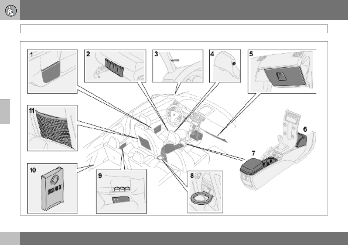
04 Interior
84
Storage spaces in the passenger compartment
04
04 Interior
85
Storage spaces in the passenger compartment
04
Storage spaces
1. Storage compartments in doors
2. Storage pocket on front edge of front
seat cushions (trim dependent)
3. Ticket clip
4. Coat hanger, only for light garments
5. Glovebox
6. Storage compartment
7. Storage compartment (e.g. for CD
discs) and cup holder1
8. Bottle holder (option)
9. Storage compartments in rear side
panels with space for up to three soda
cans
10.Storage compartment for first aid
11.Storage pockets for maps and maga-
zines
Glovebox
1. Unlocking
2. Locking
The owner’s manual and maps can be kept
here. There are also holders for coins, pens
and fuel cards. The glovebox can be locked
manually with the detachable key blade in
the remote control. More information on the
key blade is on page 95.
Floor mats (option)
Volvo supplies floor mats which are especial-
ly produced for your car.
1Storage compartment in certain markets.
WARNING
Ensure that no hard, sharp or heavy objects
lie or protrude in such a way that they could
cause injury during heavy braking.
Always secure large and heavy objects with
a seatbelt or cargo retaining straps.
WARNING
The floor mat at the driver’s seat must be
firmly fitted and secured in the attachment
clips to prevent it from being trapped
around and under the pedals.
04 Interior
86
Rear seat
04
Lowering the rear seat backrest
The rear seat backrests can be tipped for-
wards together, or individually, to make it
easier to transport long objects.
Lowering the backrest:
– Pull the lock catch up and forward to
release the backrest. A red indicator (A)
shows that the backrest is no longer
locked in place.
– Fold the backrest forward.
Raising the backrest:
– Fold up the backrest.
– Place the seatbelt over the backrest.
– Press the backrest backwards into locked
position.
– Check that the backrest is locked.
Armrest in the rear seat
The armrest in the rear seat can be folded
down for passenger comfort or to make
space for a long load. The armrest folds
down when one of the backrests is folded
down.
For securing loads, see page 140.
WARNING
Place the belt straps over the backrests be-
fore folding them back to their secured po-
sitions.
NOTE
When the backrest has been raised, the red
indicator (A) should no longer be showing. If
it is still showing then the backrest is not
locked in place.
04 Interior
87
Cargo area
04
Bottle holder (option)
There is a bottle holder for larger bottles lo-
cated to the rear of the tunnel console.
Soft cargo cover (option)
Soft cargo cover
The cargo cover is pulled over the luggage
and secured in the rear load retaining eyelets.
Undo (D) and, if necessary, (C) during load-
ing.
Fitting the cargo cover
– Hook in the hooks in the front load retain-
ing eyelets by the floor (A).
– Fit the front brackets in (B) by pressing
together the spring-loaded rail and fit it
into place on both sides.
– Fit the rear brackets in (C) in the same
way.
– Hook in the hooks in the rear load retain-
ing eyelets (D).
Hanging up the cargo cover when not in
use
– Unhook the hooks from the rear load
retaining eyelets (D).
– Press the rail together and remove it from
the rear bracket (C). Place the rail at the
front of the cargo area floor.
– Hook in the hooks in the rail next to the
mounting points (B).
The cargo cover now hangs next to the rear
seat backrest ready for the next time it is to
be used.
Removing the cargo cover
– Unhook the hooks and remove one rail at
a time by pressing them together and
removing them from their mounting
points.
– When all mounting points are detached
the cargo cover can be rolled up and
placed at the rear of the cargo area floor to
make space for bulky loads.
NOTE
The cargo cover has no load-securing func-
tion Never load anything on top of the cargo
cover. For securing loads, see page 140.
04 Interior
88
Cargo area
04
Hard cargo cover (option)
Fitting the cargo cover
– Retract all four lock plungers by pulling the
lock buttons to their end positions before
lifting in the cargo cover into the cargo
area. The lock plungers stop in retracted
position.
– Lift the cargo cover carefully into the
cargo area sideways, turn it back around
and angle the front edge up slightly.
Locks and support pins
– Locate the front section of the two support
pins behind the active locks (A) on both
sides.
– Align one of the rear locks at (B) and
extend the lock plunger by moving the
lock button forwards.
– Align the other rear lock in the same way
and extend the lock plunger by moving the
lock button forwards.
– Extend the front lock plungers, one at a
time so that they lock in their active
locks (A).
The cargo cover hatch can be raised during
loading.
Removing the cargo cover
– Retract the front lock plungers at (A) to
their end positions by pulling back the lock
buttons on both sides.
– Retract the rear lock plungers at (B) to
their end positions by pulling back the lock
buttons on both sides.
– Lift up and turn the cargo cover before
lifting it from the cargo area.
NOTE
The cargo cover has no load-securing func-
tion Never load anything on top of the cargo
cover. For securing loads, see page 140.
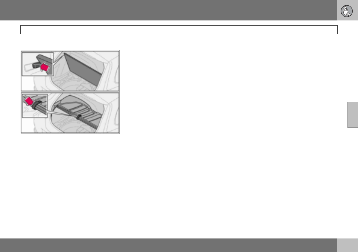
04 Interior
89
Cargo area
04
Raising the floor hatch
Without cargo cover
Raise the floor hatch and secure it in the lugs
on both sides.
With hard cargo cover
Raise the hatch on the cargo cover. Then
raise the floor hatch and hook it into the hook
located under the cargo cover.
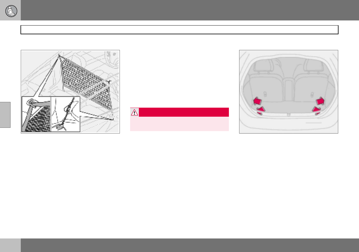
04 Interior
90
Cargo area
04
Safety net (option)
The safety net is located behind the front
seat backrests. The safety net is only de-
signed for use when the rear seat backrests
are lowered. For securing loads, see
page 140.
Fitting the safety net
– Fold down the backrests on both sides,
see page 86.
– Secure the safety net in the roof panel
mountings.
– Secure the hooks in the eyes at the seat-
belt floor mounting on both sides.
– Stretch the straps if necessary.
– Check all mountings.
Removing the safety net
– Slacken the tension from the straps.
– Undo the hooks from the eyes at the
seatbelt floor mounting on both sides.
– Detach the net from the mounting points
in the roof panels.
– Fold up the safety net and store it in the
bag.
Load retaining eyelets
The load retaining eyelets1 are used to fasten
straps or nets to secure items in the cargo ar-
ea.
There are two further eyelets on each side by
the seatbelt slide rail that can be used for se-
curing loads when the safety net is not in use.
For securing loads, see page 140.
WARNING
Cargo area loads must be well secured
even if the safety net is correctly fitted.
1Option in certain markets.

04 Interior
91
04

92
Remote control with key blade ................................................................94
Keyless drive (option) ...............................................................................98
Locking and unlocking ...........................................................................100
Alarm (option) .........................................................................................103
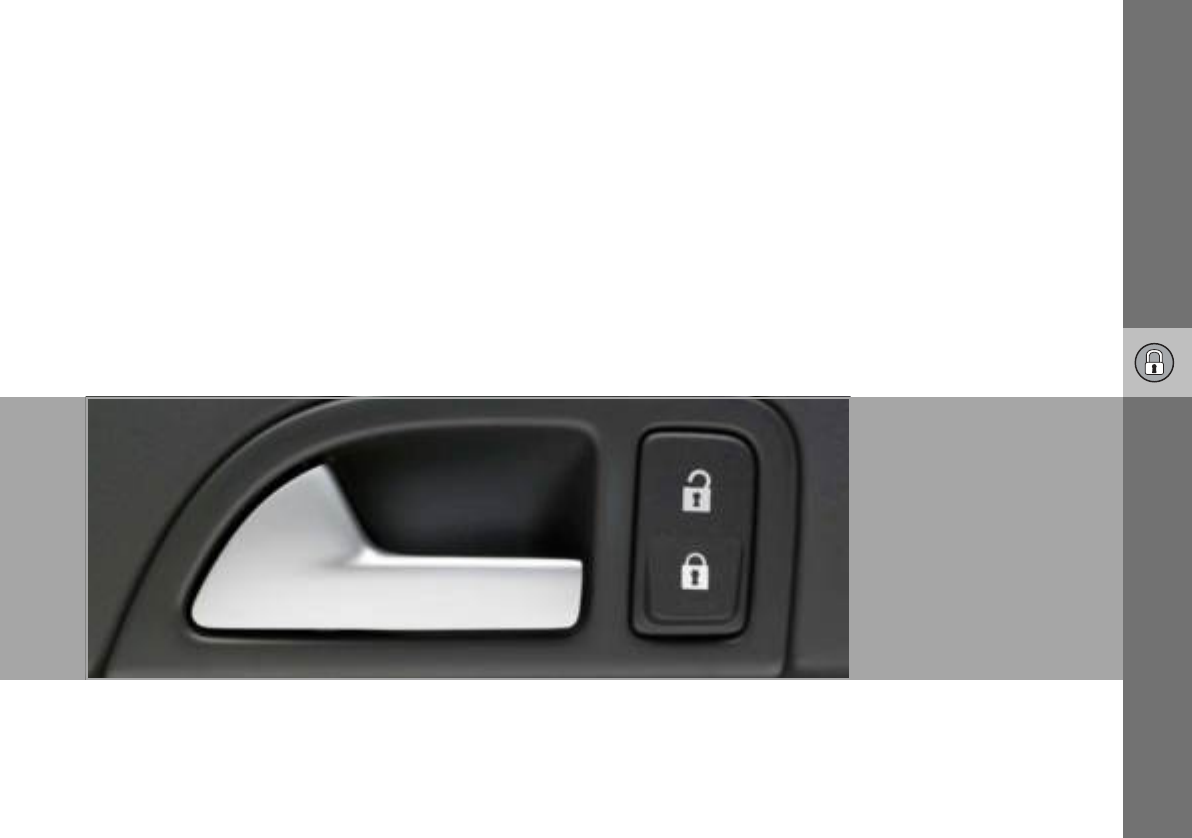
05
LOCKS AND ALARM
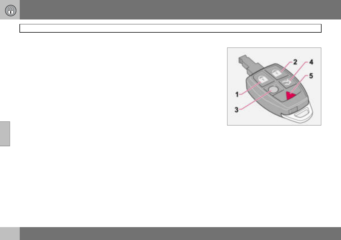
05 Locks and alarm
94
Remote control with key blade
05
Remote control
The car is supplied with two remote controls.
They also serve as ignition keys. The remote
controls contain detachable metal key blades
for mechanical locking/unlocking of the driv-
er’s door and glovebox.
The key blades’ unique code is available at
authorised Volvo workshops, who can order
new key blades.
A maximum of six remote controls/key
blades can be programmed and used for one
single car.
Flashing lock indicator for locking/
unlocking
When the car is locked using the Keyless
drive system or the remote control, one long
flash signal of the direction indicators serves
to indicate that locking was correctly per-
formed. The indication is only given if all
locks are activated once the doors have been
closed. Correct unlocking is indicated by two
short flashes.
Personal preferences can be used to deacti-
vate indication via the direction indicators.
There will then be no visual indication as to
whether the lock status is correct. See
page 64.
Loss of a remote control
If you lose a remote control, take the car and
the other remote controls to an authorised
Volvo workshop. The code of the missing re-
mote control must be erased from the sys-
tem as a theft prevention measure.
Immobiliser
The remote controls are fitted with coded
chips. The code must be accepted by the
reader (receiver) in the ignition switch. The
car can only be started if the correct remote
control with the correct code is used.
Remote control functions
1. Locking – Locks both doors and the
tailgate. Press and hold to also close the
side windows and the sunroof if fitted.
2. Unlocking – Unlocks both doors and
the tailgate.
3. Approach lighting – When you ap-
proach the car:
Press the yellow button on the remote
control to switch on the interior lighting,
position/parking lamps, number plate
lighting and door mirror lamps (option).
The lighting is switched off automati-
cally after 30, 60 or 90 seconds. For
information on setting the delay time,
see page 65.
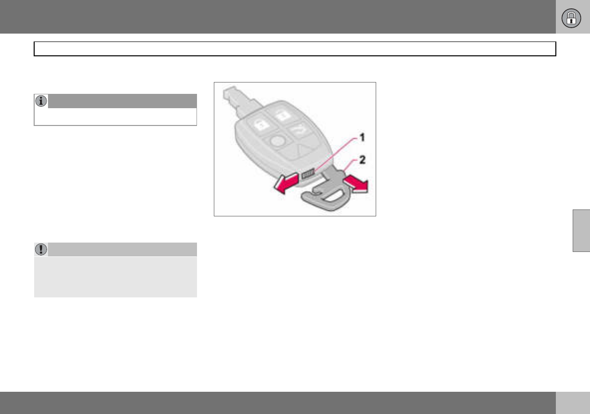
05 Locks and alarm
95
Remote control with key blade
05
4. Tailgate – Press the button once to
unlock the tailgate only.
5. Panic function – Used to attract atten-
tion in an emergency. Press and hold
the red button for at least three sec-
onds or press it twice within three
seconds to activate the direction indi-
cators and the horn. The function can
be turned off with the same button
once it has been active for at least
5 seconds. Otherwise the function
switches off automatically after
30 seconds.
Key blade
This feature is intended for when leaving the
car, such as for servicing or valet parking at a
hotel etc. Hand over the remote control and
keep the detachable key blade.
Removing the key blade
Take the key blade from the remote control:
– Slide the spring-loaded catch (1) to the
side while pulling the key blade (2) out
backwards.
Inserting the key blade
Be careful when inserting the key blade back
into the remote control.
– Hold the remote control with the narrow
end pointing down and lower the key
blade into its slot.
– Lightly press the key blade to lock it in
position. You should hear a "click".
NOTE
The function does not open the tailgate.
IMPORTANT
The narrow section of the remote control is
particularly sensitive - this contains the
chip. The car cannot be started if the chip is
damaged.
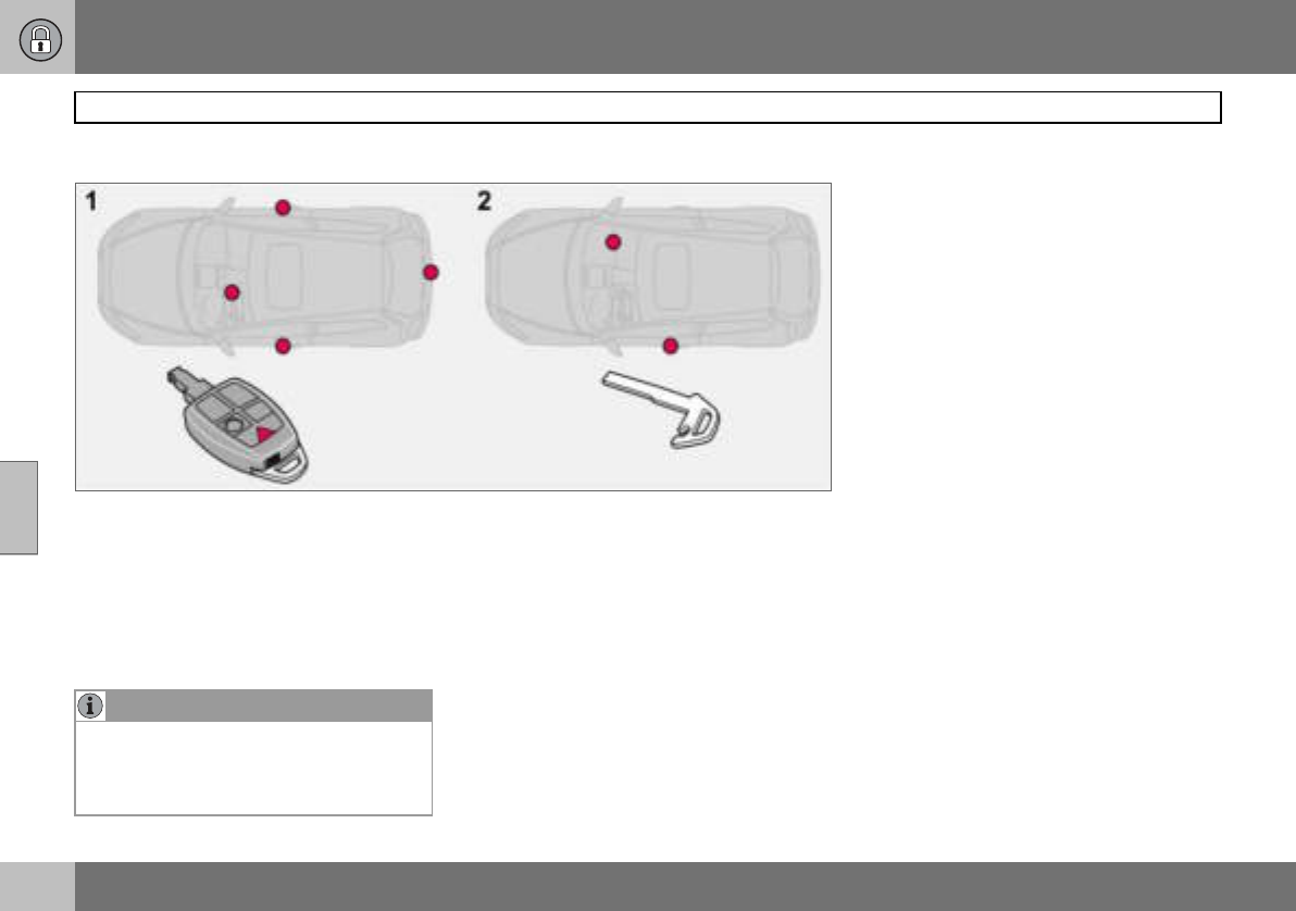
05 Locks and alarm
96
Remote control with key blade
05
Key blade
Active locks
1. Active locks, remote control
2. Active locks, key blade
The detachable key blade of the remote con-
trol is used to lock or unlock the glovebox or
driver’s door (without activating the central
locking system).
NOTE
Using the detachable key blade of the re-
mote control to unlock the driver’s door will
trigger the alarm. Switch off the alarm with
the remote control. See page 104.
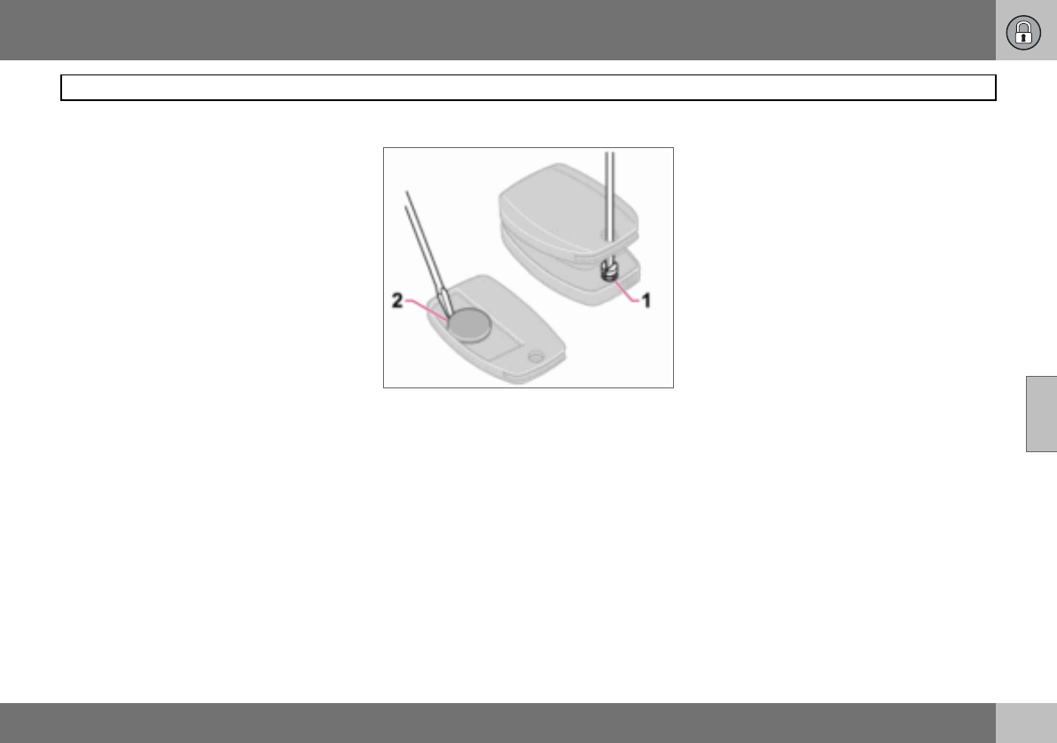
05 Locks and alarm
97
Remote control with key blade
05
Weak remote control battery
When the battery runs down and full func-
tionality cannot be guaranteed, the informa-
tion symbol and REMOTE BATTERY LOW
VOLTAGE appear on the display.
Replacing the remote control battery
If the locks repeatedly fail to respond to sig-
nals from the remote control at a normal dis-
tance, the battery should be replaced (type
CR 2032, 3 V).
– Pull out the key blade.
– Place the remote control with the keypad
downward and remove the screw (1) using
a small screwdriver.
– Remove the cover.
– Carefully note the position of the battery’s
+ and – poles on the inside of the cover.
– Prise out (2) and change the battery. Avoid
touching the battery and its terminals with
your fingers.
– Refit the cover and screw it shut.
– Press the key blade back into place.
Dispose of the old battery in an environmen-
tally-friendly way.
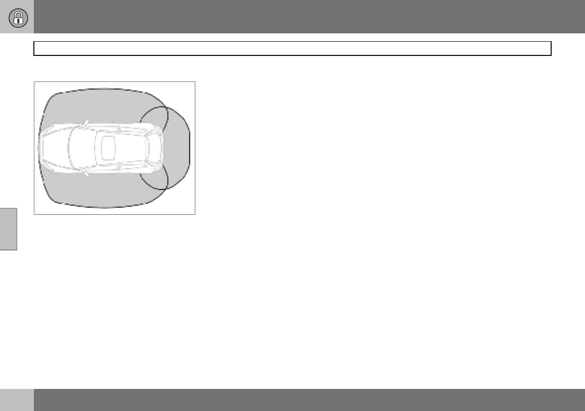
05 Locks and alarm
98
Keyless drive (option)
05
Keyless lock and ignition system
The keyless drive system allows the car to be
unlocked, driven and locked without the
need for a key. You simply need to have the
remote control with you in a pocket or a bag.
The system makes it easier and more con-
venient to open the car, for example with
shopping bags in one hand and a child in the
other. It saves you having to take out or look
for the remote control.
The two remote controls incorporate the key-
less drive feature. You can order additional
remote controls. The keyless drive system
can handle up to six remote controls.
Remote control max. 1.5 m from the car
In order to open a door or the tailgate, a re-
mote control must be no more than approx.
1.5 metres from the car door handle or tail-
gate.
This means that the person who wishes to
open a door must have the remote control
with him or her. It is not possible to open a
door if the remote control is on the other side
of the car.
The grey areas in the illustration indicate the
range covered by the system’s antennas.
If someone leaves the car and takes a key-
less drive remote control with them, a warn-
ing message appears on the information dis-
play and a reminder signal sounds. The
warning message disappears when the re-
mote control is brought back to the car or
when the ignition dial is turned to position 0.
The warning is only issued if the ignition dial
is in position I or II after someone has
opened and closed a door.
The warning message and reminder signal
disappear when the remote control is
brought back to the car after one of the fol-
lowing actions:
• a door has been opened and closed
• the ignition dial has been turned to
position 0
•the READ button has been pressed.
Never leave any remote control in the
car
If a remote control with keyless drive function
is left in the car, it is made passive when the
car is locked. This prevents unauthorised en-
try.
If someone breaks into the car and finds the
remote control, it can be activated and used
again. It is therefore important to handle all
remote controls with equal care.
Interference to remote control function
Electromagnetic screening and fields can in-
terfere with the keyless drive system. To
avoid this: do not place the remote control
near mobile phones, metallic objects or, for
example, in a metal briefcase.
If interference is experienced nonetheless,
use the remote control and key blade in the
normal way, see page 94.
05 Locks and alarm
99
Keyless drive (option)
05
Unlocking
When the remote control is within the range
covered by the system’s antennas:
– Open the doors by pulling the relevant
handle.
– Open the tailgate by pressing under the
tailgate opening button and lift the tail-
gate.
If for some reason the keyless drive function
in the remote control is not operating, the car
can be unlocked using the remote control
functions, see page 94.
Unlocking using the key blade
The driver’s door can be opened as follows
(central locking system not activated):
– Carefully prise out the plastic cover in the
handle by inserting the key blade in the
hole on the bottom of the cover.
– Unlock the door using the key blade.
Power seat (option) – remote control
with memory function
If several people with keyless drive remote
controls get into the car, then the driver’s
seat will be adjusted for the person who
opens the door first.
Locking
Lock the doors and tailgate as follows:
– Push in the lock button on one of the door
handles.
Both doors and the tailgate must be closed
before the lock button can be pressed. Oth-
erwise they will not lock.
When the car is locked, the lock buttons on
the inside of the doors retract.
Personal preferences
The Keyless Drive system can have personal
preferences applied, see page 65.
05 Locks and alarm
100
Locking and unlocking
05
Locking/unlocking the car from
outside
Unlocking
The remote control unlock button can unlock
the car in two different ways (select option in
personal preferences, see page 65):
• with one press unlock both doors and the
tailgate
• with one press unlock the driver’s door
and with a second press unlock the other
door and the tailgate.
Locking
The remote control locks both doors and the
tailgate simultaneously. Door lock buttons
and inside door handles are disengaged.
The fuel filler flap cannot be opened if the car
is locked with the remote control.
Automatic relocking
If none of the doors or the tailgate is opened
within two minutes of unlocking, all are
locked again automatically (does not apply to
locking from inside). This function reduces
the risk of the car being left unlocked unin-
tentionally. For cars with alarms, see
page 104.
Automatic locking
When the speed of the car exceeds 7 km/h
the doors and tailgate can be locked auto-
matically.
When the function is activated and the doors
have been locked they can be opened in two
ways:
• pull one of the door handles twice
• press the unlock button by the door han-
dle.
The function can be activated/deactivated by
means of personal preferences, see page 65.
Tailgate
Unlocking
Unlocking tailgate only:
– Press the remote control button to unlock
the tailgate.
Locking
If the doors are locked when the tailgate is
closed then it remains unlocked. Lock with
the remote control or from inside to lock both
doors and the tailgate.
NOTE
The car can be locked1 even if a door or the
tailgate is open. When the door is closed
there is a risk that the keys will be locked in.
1Applies to certain markets
WARNING
Be aware that you can be locked in the car if
it is locked from the outside with the remote
control. You cannot then leave the car using
any of the controls inside the car.
05 Locks and alarm
101
Locking and unlocking
05
Locking/unlocking from inside
The doors and the tailgate can be locked or
unlocked simultaneously using the lock but-
ton by the door handle.
Unlocking
– Press the upper section of the lock button.
Press and hold to also open all side win-
dows.
Locking
– Press the lower section of the lock button.
Press and hold to also close all of the
windows and the sunroof if fitted.
Both doors and tailgate are locked with the
lock button in the driver’s or passenger door.
Opening the doors
When the doors are locked from the inside:
– Pull the handle twice to unlock and open
the doors.
Locking the glovebox
The glovebox can only be locked and un-
locked with the detachable key blade in the
remote control.
• Unlock the glovebox (1) by turning the key
a quarter of a turn (90 degrees) anticlock-
wise. The keyhole is vertical in the un-
locked position.
•Lock (2) the glovebox by turning the key a
quarter of a turn (90 degrees) clockwise.
The keyhole is horizontal in the locked
position.
05 Locks and alarm
102
Locking and unlocking
05
Deadlocks
When deadlocked, the doors cannot be
opened from the inside if they are locked.
This is activated with the remote control. The
deadlocks are set after a 25 second delay af-
ter the doors are locked.
The car can only be unlocked from the dead-
lock mode with the remote control. The
doors can also be opened from the outside
with the key.
1. Deactivation of the detectors and dead-
locks
2. No function
Temporary deactivation of the
deadlocks and any alarm detectors
If someone is going to stay in the car but you
still want to lock the doors from the outside,
the deadlocks can be disabled.
– Insert the key into the ignition switch, turn
it to position II and then back to position
I or 0.
– Press the button (1).
If the car is equipped with an alarm, the
movement and tilt detectors are also deacti-
vated at the same time, see page 104.
The light in the button illuminates until the car
is locked with the key or the remote control.
A message remains on the display as long as
the key remains in the ignition switch. The
detectors are reactivated and deadlocks re-
engaged the next time the ignition is
switched on.
WARNING
Do not allow anyone to remain in the car
without first deactivating the deadlocks.
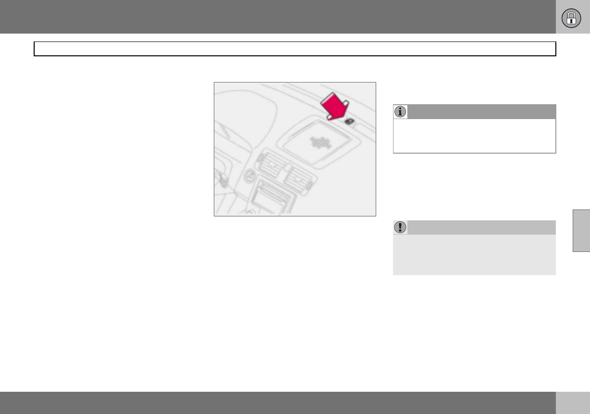
05 Locks and alarm
103
Alarm (option)
05
Alarm system
When the alarm is armed, it continually moni-
tors all alarm inputs.
The alarm is triggered if:
• a door, the bonnet or tailgate opens
• a non-approved key is used in the ignition
or if an attempt is made to force the lock
• a movement is detected in the passenger
compartment (if fitted with a movement
detector)
• the car is raised or towed away (if fitted
with a tilt detector)
• a battery cable is disconnected
• anyone tries to disconnect the siren.
Alarm lamp on instrument panel
A light on the instrument panel indicates the
alarm system’s status:
• Lamp not lit – the alarm is not armed.
• The lamp flashes rapidly after disarming
the alarm and until the ignition is switched
on – the alarm has been triggered.
• The lamp flashes once every other second
after the car’s direction indicators have
given one long flash – the alarm is armed.
If there is a fault in the alarm system, a mes-
sage appears on the information display.
Contact an authorised Volvo workshop.
Arming the alarm
– Press the lock button on the remote con-
trol. A long flash from the car’s direction
indicators confirms that the alarm is
armed and that all the doors are locked.
Disarming the alarm
– Press the unlock button on the remote
control. Two short flashes from the car’s
direction indicators confirms that the
alarm is disarmed and that both doors are
unlocked.
NOTE
Do not attempt to repair or modify alarm
system components. All such attempts
could affect the terms of insurance.
IMPORTANT
The alarm is fully armed when the car’s di-
rection indicators have made one long flash
and the light on the dashboard flashes once
per second.
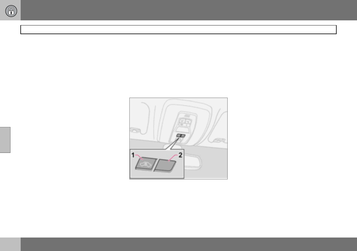
05 Locks and alarm
104
Alarm (option)
05
Automatic alarm activation
This function prevents you accidentally leav-
ing the car without the alarm on.
If none of the doors or the tailgate are
opened within two minutes of disarming the
alarm (and the car has been unlocked with
the remote control), the alarm is automatical-
ly rearmed. The car is locked at the same
time.
Deactivating a triggered alarm
– Press the unlock button on the remote
control or insert the key in the ignition
switch.
Confirmation is given by two short flashes
from the direction indicators.
Alarm signals
When the alarm is triggered, the following
happens:
• A siren sounds for less than 25 seconds.
The siren has its own battery which is
used if the car battery has insufficient
charge or is disconnected.
• The direction indicators flash for five min-
utes or until the alarm is deactivated.
Remote control not working
If for some reason the remote control is not
working, the alarm can still be switched off
and the car started as follows:
– Open the driver’s door with the key blade.
The alarm is triggered and the siren
sounds.
– Insert the remote control into the ignition
switch. The alarm is deactivated. The
alarm lamp flashes rapidly until the ignition
key is turned to position II.
Temporary deactivation of the
deadlocks and alarm detectors
1. Deactivation of the detectors
2. No function
To prevent the alarm being triggered errone-
ously, such as during a ferry journey, the
movement and tilt detectors can be tempo-
rarily disengaged.
– Turn the ignition key to position II and then
back to position 0. Remove the key.
– Press button (1). The lamp in the button is
illuminated until the car is locked.
A message remains on the display as long as
the key remains in the ignition switch (or for
one minute after the key is removed).
The detectors are reactivated the next time
the ignition is switched on.
If the car has deadlocks, these are also re-
engaged.

05 Locks and alarm
105
Alarm (option)
05
Testing the alarm system
Testing the movement detector in the
passenger compartment
– Open all windows.
– Arm the alarm. Activation of the alarm is
confirmed by the lamp flashing slowly.
– Wait 30 seconds.
– Test the movement detector in the pas-
senger compartment, such as by lifting
out a bag from a seat. A siren should
sound and all direction indicators should
flash.
– Deactivate the alarm by unlocking the car
with the remote control.
Testing the doors
– Arm the alarm.
– Wait 30 seconds.
– Unlock the driver’s door with the key
blade.
– Open one of the doors. A siren should
sound and all direction indicators should
flash.
– Deactivate the alarm by unlocking the car
with the remote control.
Testing the bonnet
– Sit in the car and deactivate the move-
ment detector.
– Arm the alarm. Remain in the car and lock
the doors with the button on the remote
control.
– Wait 30 seconds.
– Open the bonnet with the handle under
the dashboard. A siren should sound and
all direction indicators should flash.
– Deactivate the alarm by unlocking the car
with the remote control.

106
General ................................................................................................... 108
Refuelling ............................................................................................... 110
Starting the engine ..................................................................................111
Keyless drive (option) ............................................................................. 113
Manual gearbox ..................................................................................... 114
Automatic gearbox ................................................................................ 116
Brake system ......................................................................................... 119
Stability and traction control
system .................................................................................................... 121
Parking assistance (option) .................................................................... 123
Blind Spot Information System BLIS
(option) ................................................................................................... 125
Towing and recovery .............................................................................. 128
Jump starting ......................................................................................... 130
Driving with a trailer ...............................................................................131
Towing bracket ....................................................................................... 133
Detachable towbar ................................................................................. 135
Loading .................................................................................................. 140
Adjusting headlamp pattern ................................................................... 141
06
STARTING AND DRIVING
06 Starting and driving
108
General
06
Economical driving
Driving economically means driving smoothly
while thinking ahead and adjusting your driv-
ing style and speed to the prevailing condi-
tions.
• Get the engine warmed up as soon as
possible.
• Do not let the engine idle, but drive at light
loads as soon as it is possible. A cold
engine consumes more fuel than a warm
one.
• Avoid sudden unnecessary acceleration
and heavy braking.
• Do not drive with unnecessary loads in the
car.
• Do not use winter tyres when the roads
are dry.
• Remove the load carrier when it is not in
use.
• Avoid driving with open windows.
Slippery driving conditions
Practise driving on slippery surfaces under
controlled conditions to learn how the car re-
acts.
Engine and cooling system
Under special conditions, for example when
driving in hilly terrain, extreme heat or with
heavy loads, there is a risk that the engine
and cooling system will overheat.
Avoid overheating the cooling system
• Maintain a low speed when driving with a
trailer up long, steep ascents.
• Do not turn the engine off immediately you
stop after a hard drive.
• Remove any auxiliary lamps from in front
of the grille if driving in extreme high
temperatures.
Avoid overheating the engine
Do not exceed engine speeds of 4500 rpm
(diesel engines: 3500 rpm) if driving with a
trailer or caravan in hilly terrain. The oil tem-
perature could then become too high.
Open tailgate
Avoid driving with the tailgate open. If it is
necessary to drive with the tailgate open for a
short distance:
– Close all windows.
– Set the air distribution to the windscreen
and floor and run the fan at high speed.
Driving in water
The car can be driven through water at a
maximum depth of 25 cm at a maximum
speed of 10 km/h. Extra caution should be
exercised when passing through flowing wa-
ter.
When driving in water, maintain a low speed
and do not stop the car. When the water has
been passed, depress the brake pedal lightly
and check that full brake function is
achieved. Water and mud for example can
make the brake linings wet resulting in de-
layed brake function.
Clean the electric contacts of the electric en-
gine block heater and trailer coupling after
driving in water and mud.
WARNING
Do not drive with the tailgate open. Toxic
exhaust fumes can be drawn into the car
through the cargo area.
IMPORTANT
Engine damage can occur if water enters
the air filter.
In greater depths, water can enter the trans-
mission. This reduces the lubricating ability
of the oils and shortens the service life of
the systems.
06 Starting and driving
109
General
06
Do not overload the battery
The electrical functions in the car load the
battery to varying degrees. Avoid having the
ignition key in position II when the engine is
turned off. Use ignition position I instead, as
less power is consumed.
Examples of functions that use a lot of pow-
er:
• ventilation fan
• windscreen wipers
• audio equipment (high volume)
•parking lamps
Also, be aware of different accessories that
load the electrical system. Do not use func-
tions which use a lot of power when the en-
gine is switched off.
If the battery voltage is low, a message ap-
pears on the display. The energy-saving
function shuts down certain functions or re-
duces the load on the battery by, for exam-
ple, slowing the ventilation fan and switching
off the audio system. Charge the battery by
starting the engine.
IMPORTANT
Do not let the car stand with water over the
sills for any long period of time. This could
cause electrical malfunctions.
In the event of stalling in water, do not try to
restart. Tow the car from the water.
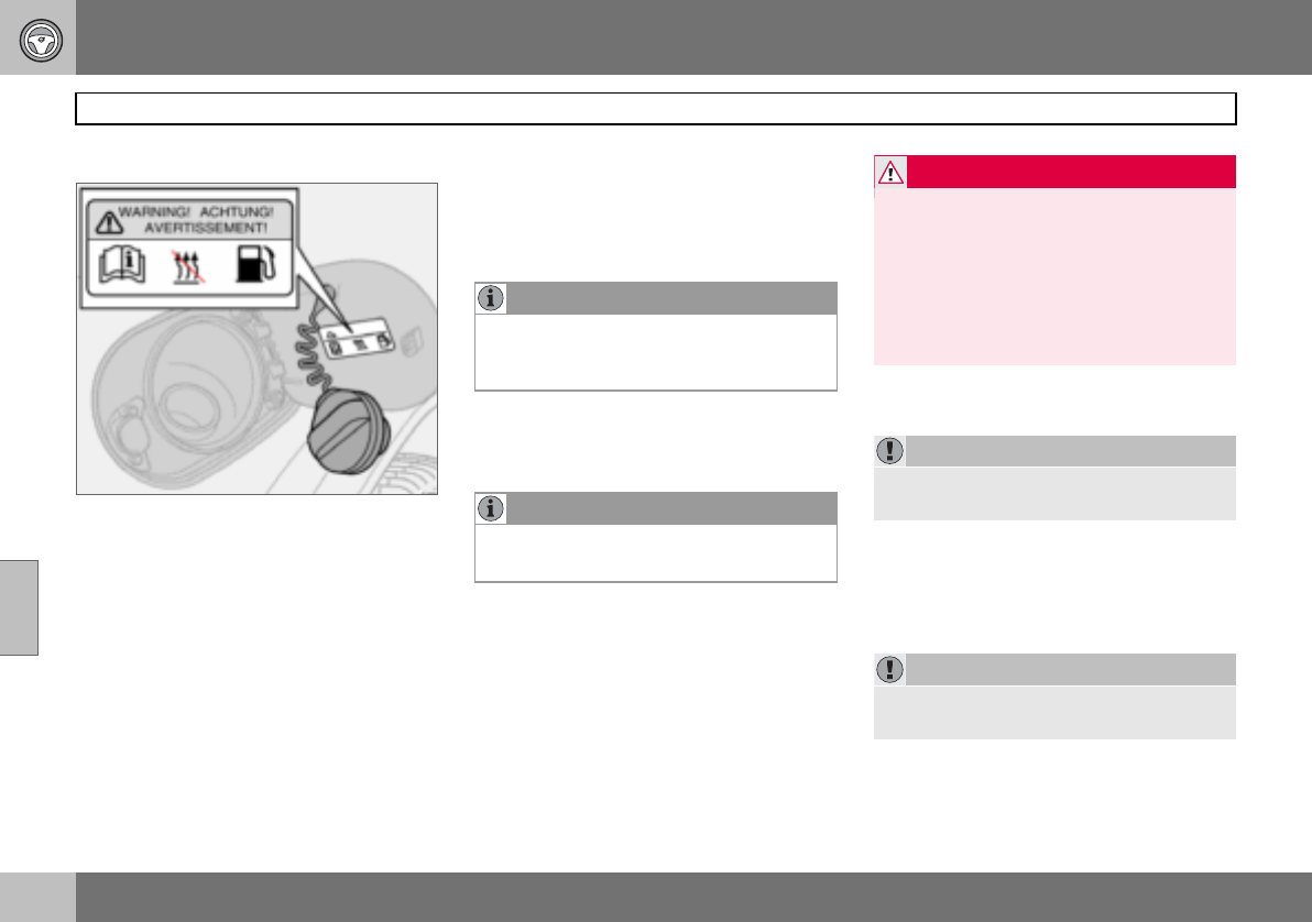
06 Starting and driving
110
Refuelling
06
Opening the fuel filler flap
Switch off the fuel-driven heater before refuel-
ling.
Open the fuel filler flap with the button on the
lighting panel, see page 47. The engine must
be switched off before the flap can be
opened. The fuel flap is located on the rear
right wing.
Closing
Push in the flap until you hear a click.
Fuel cap
1. Turn the fuel cap until an obvious resist-
ance is felt.
2. Turn past the resistance until it comes
to a stop.
3. Take out the cap.
4. Hang up the cap on the inside of the
fuel filler flap.
Filling up with fuel
Do not overfill the tank but fill until the pump
nozzle cuts out.
Fuel of a lower quality than that specified on
page 233 should not be used as engine pow-
er and fuel consumption can be negatively
affected.
Petrol
Diesel
At low temperatures (–5 C to –40 C), a par-
affin precipitate may form in the diesel fuel,
which can lead to ignition problems.
NOTE
Put the petrol cap back on after refuelling.
Turn until one or more clear clicks are
heard.
NOTE
Excess fuel in the tank can overflow in hot
weather.
WARNING
Fuel which spills onto the ground can be ig-
nited by the exhaust fumes.
Switch off the fuel-driven heater before
starting to refuel.
Never carry an activated mobile phone
when refuelling. The ring signal could cause
spark build-up and ignite petrol fumes,
leading to fire and injury.
IMPORTANT
Do not add cleaning additives to the petrol,
unless recommended by Volvo.
IMPORTANT
Use special winter grade fuel during cold
months.
06 Starting and driving
111
Starting the engine
06
Before starting the engine
– Apply the parking brake.
Automatic gearbox
– Gear selector in position P or N.
Manual gearbox
Put the gear lever in neutral and hold the
clutch pedal fully depressed. This is particu-
larly important in very cold conditions.
Starting the engine
Petrol
– Turn the ignition key to position III.
If the engine does not start within
5–10 seconds, release the key and try
again.
Diesel
1. Turn the ignition key to position II.
An indicator symbol in the combined in-
strument panel shows that engine pre-
heating is underway, see page 41.
2. Turn the ignition key to position III
when the indicator symbol goes out.
Autostart (5-cylinder)
With the autostart function, there is no need
to hold the ignition key (or ignition dial on
cars with Keyless Drive, see page 113) in
position III until the engine has started.
Turn the ignition key to the start position and
then release. The starter motor then works
automatically until the engine has started.
Diesel particle filter (DPF)
Diesel cars are equipped with a particle filter,
which results in more efficient emission con-
trol. The particles in the exhaust gases are
collected in the filter during normal driving.
So-called "regeneration" is started in order to
burn away the particles and empty the filter.
This requires the engine to have reached nor-
mal operating temperature.
Regeneration of the filter takes place auto-
matically at an interval of approximately
300 – 900 km depending on driving condi-
tions. Regeneration normally takes between
10 and 20 minutes. During this time fuel con-
sumption may increase slightly.
The rear window heating may be activated
automatically to increase the load on the en-
gine during regeneration without warning.
Regeneration in cold weather
If the car is frequently driven short distances
in cold weather then the engine does not
reach normal operating temperature. This
means that regeneration of the diesel particle
filter does not take place and the filter is not
emptied.
When the filter has become approximately
80 % full of particles, a yellow warning trian-
gle illuminates on the dashboard, and the
WARNING
Never remove the ignition key from the
steering lock while driving or when the car is
being towed. The steering lock could other-
wise be activated, making it impossible to
steer the car.
The ignition key must be in position II when
the car is being towed.
NOTE
The idling speed can be noticeably higher
than normal for certain engine types during
cold starting. This is in order that the emis-
sions system can reach normal operating
temperature as quickly as possible, which
minimises exhaust emissions and protects
the environment.
NOTE
If the diesel engine is started in extreme
cold without waiting for engine preheating,
then the automatic start sequence can be
delayed for a couple of seconds.
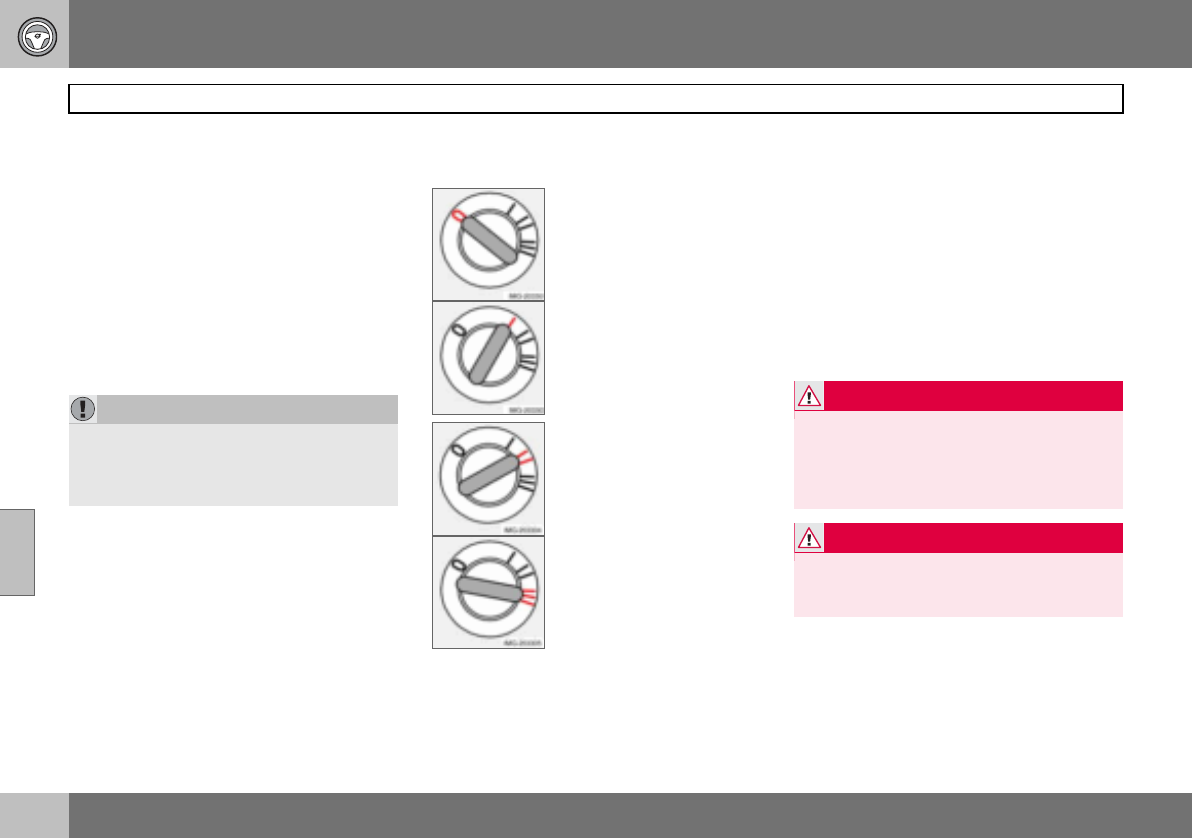
06 Starting and driving
112
Starting the engine
06
message, SOOT FILTER FULL SEE MANU-
AL is shown on the dashboard display.
Start regeneration of the filter by driving the
car until the engine reaches normal operating
temperature, preferably on a main road or
motorway. The car should then be driven for
approximately 20 minutes more. When re-
generation is underway the engine power is
reduced.
When regeneration is complete the warning
message is cleared automatically.
Use the parking heater (option) in cold
weather so that the engine reaches normal
operating temperature more quickly.
Ignition keys and electronic
immobiliser
The ignition key must not hang with other
keys or metal objects on the same key ring.
The electronic immobiliser could be activated
accidentally.
Ignition switch and steering lock
0 – Locked position
The steering lock is activat-
ed when the key is removed
from the lock.
I – Radio position
Certain electrical compo-
nents can be switched on.
The engine’s electrical sys-
tem is not activated.
II – Driving position
The key position when driv-
ing. The car’s electrical sys-
tem is energised.
III – Start position
The starter motor is en-
gaged. When the key is re-
leased it springs back auto-
matically to the driving po-
sition, once the engine has
started.
A ticking sound may be heard if the key is be-
tween positions. Turn the key to position II
and back to eliminate the sound.
When the steering lock is activated
If the front wheels are positioned so that
there is tension in the steering lock, a warn-
ing message may be shown on the informa-
tion display and the car prevented from start-
ing.
1. Remove the key and turn the steering
wheel to release the tension.
2. Hold the steering wheel in this position.
Reinsert the key and make a new at-
tempt to start the car.
Make sure the steering lock is activated
when the car is left to reduce the risk of theft.
IMPORTANT
If the filter fills up it may be incapable of
functioning. Then it can be difficult to start
the engine and there is a risk that the filter
will have to be replaced.
WARNING
Never remove the ignition key from the igni-
tion switch while driving or when the car is
being towed. The steering lock would be
activated, making it impossible to steer the
car.
WARNING
Always remove the ignition key from the ig-
nition switch when leaving the car, especial-
ly if there are children in the car.
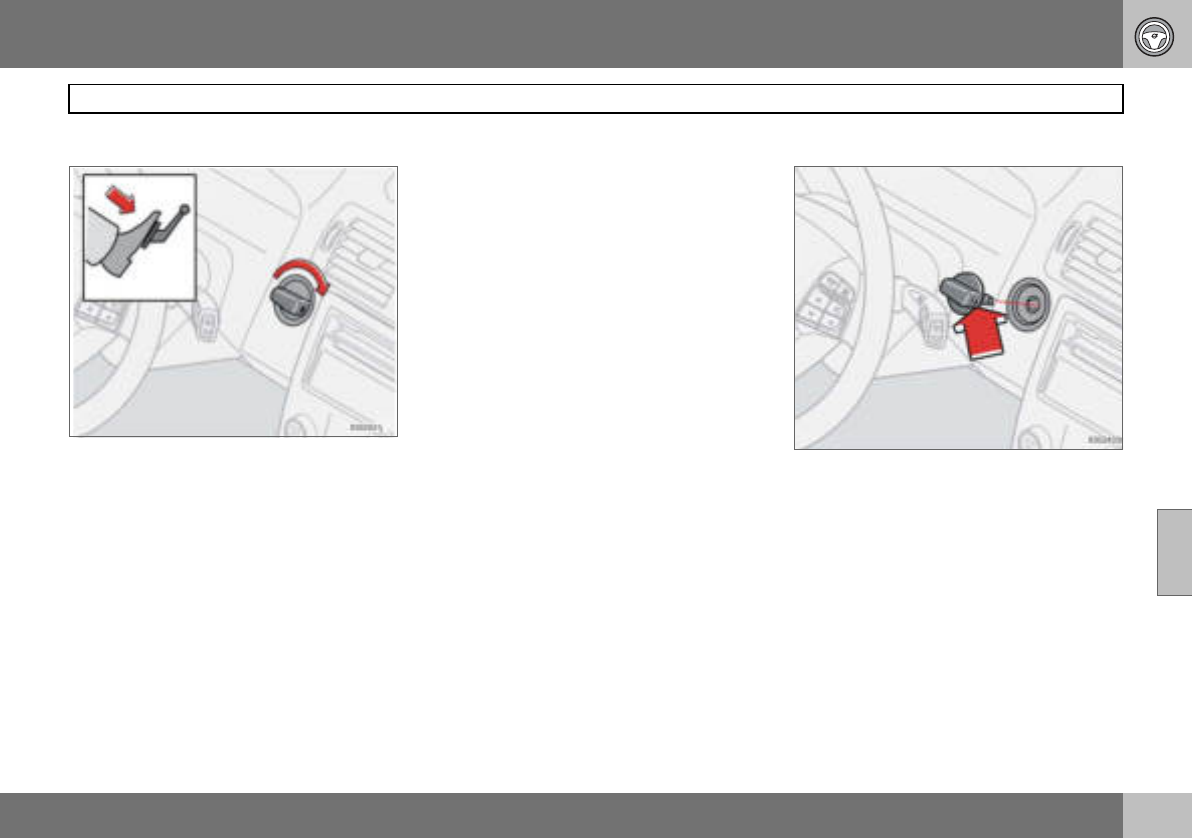
06 Starting and driving
113
Keyless drive (option)
06
General
The keyless drive function allows the car to
be unlocked, driven and locked without the
need for a key, see page 98.
The ignition switch ignition dial is used in the
same way as the key. One precondition for
starting the car is that the car’s remote con-
trol is located inside the passenger compart-
ment or the cargo area.
Starting the car
– Depress the clutch pedal (cars with manu-
al gearbox) or brake pedal (cars with auto-
matic gearbox).
Petrol engine
– Press in and turn the ignition dial to
position III.
Diesel engine
1. First turn the ignition dial to position II
and wait until the diesel indicator symbol
in the combined instrument panel goes
out, see page 41.
2. Following which, turn the ignition dial to
position III.
Starting with the remote control
If the remote control battery is discharged
then the Keyless Drive function does not
work. In which case, start the car by using
the remote control as ignition dial.
1. Press in the catch in the ignition dial and
then pull it out from the ignition switch.
2. Insert the remote control into the igni-
tion switch and start in the same way
as with the ignition dial.
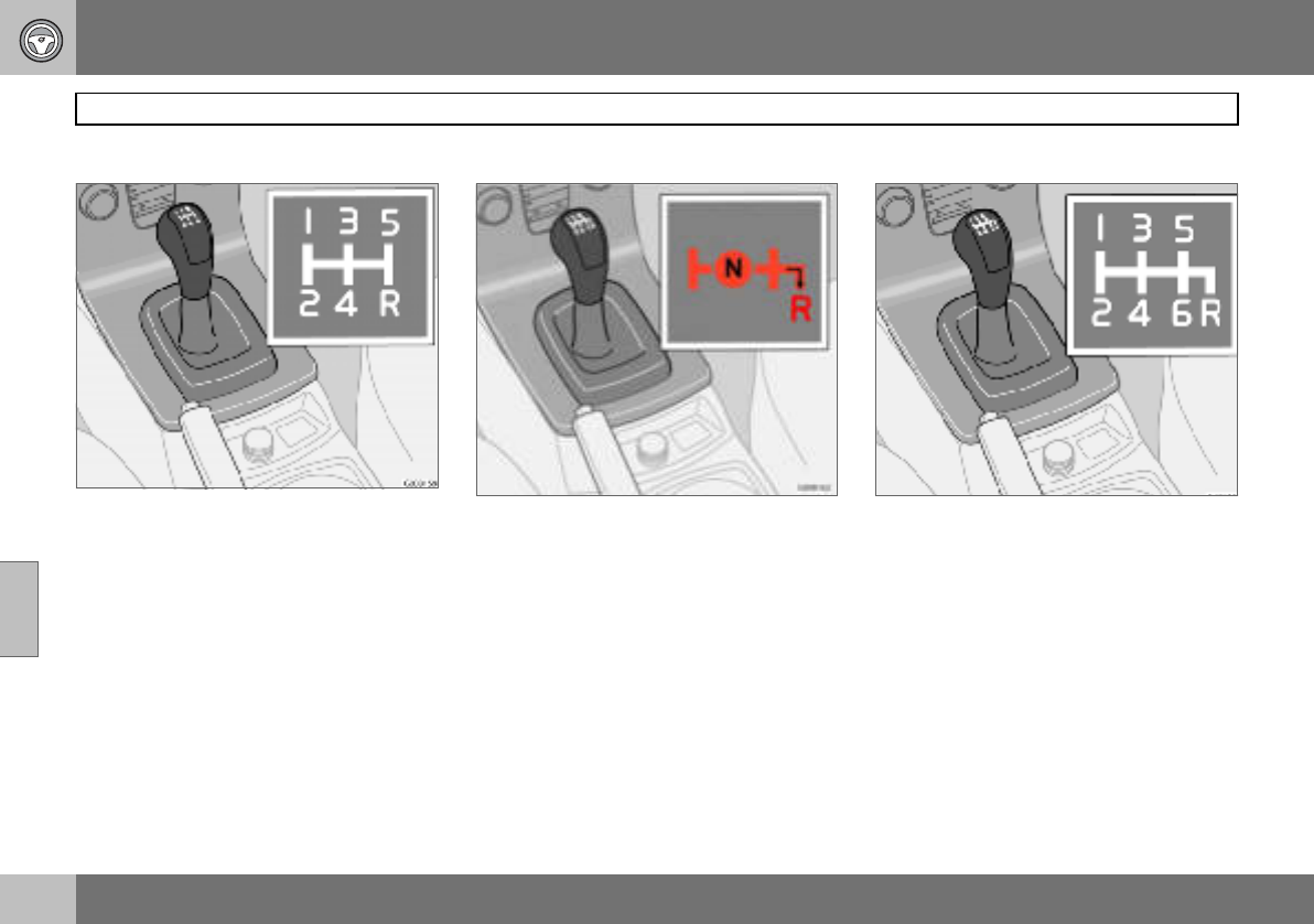
06 Starting and driving
114
Manual gearbox
06
Gear positions, five-speed
Depress the clutch pedal fully during each
gear change. Take your foot off the clutch
pedal between gear changes. Follow the
shifting pattern indicated.
For the best possible fuel economy, use the
highest gear possible as often as possible.
Reverse gear inhibitor, five-speed
Only engage reverse gear when the car is
stationary. To engage reverse gear, the gear
lever must first be put in position N. Reverse
gear cannot therefore be engaged directly
from fifth gear due to the reverse gear inhibi-
tor.
Gear positions, six-speed (petrol)
Depress the clutch pedal fully during each
gear change. Take your foot off the clutch
pedal between gear changes. Follow the
shifting pattern indicated.
For the best possible fuel economy, use the
highest gear possible as often as possible.
It can be difficult to find the positions for fifth
and sixth gear when the car is stationary as
the reverse gear inhibitor (which blocks side-
ways movement towards reverse) is then not
activated.
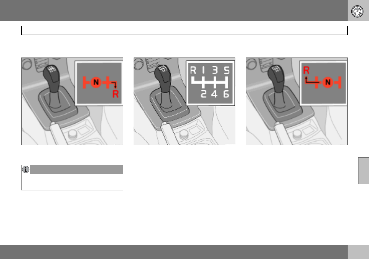
06 Starting and driving
115
Manual gearbox
06
Reverse gear inhibitor, six-speed
(petrol)
Only engage reverse gear when the car is
stationary.
Gear positions, six-speed (diesel)1
Depress the clutch pedal fully during each
gear change. Take your foot off the clutch
pedal between gear changes. Follow the
shifting pattern indicated.For the best possi-
ble fuel economy, use the highest gear possi-
ble as often as possible.
Reverse gear inhibitor, six-speed
(diesel)
Only engage reverse gear when the car is
stationary. Engage reverse gear by pressing
down the gear lever and moving it to the left.
NOTE
Reverse gear is electronically blocked if the
car is travelling faster than approx. 20 km/h.
1Certain markets.
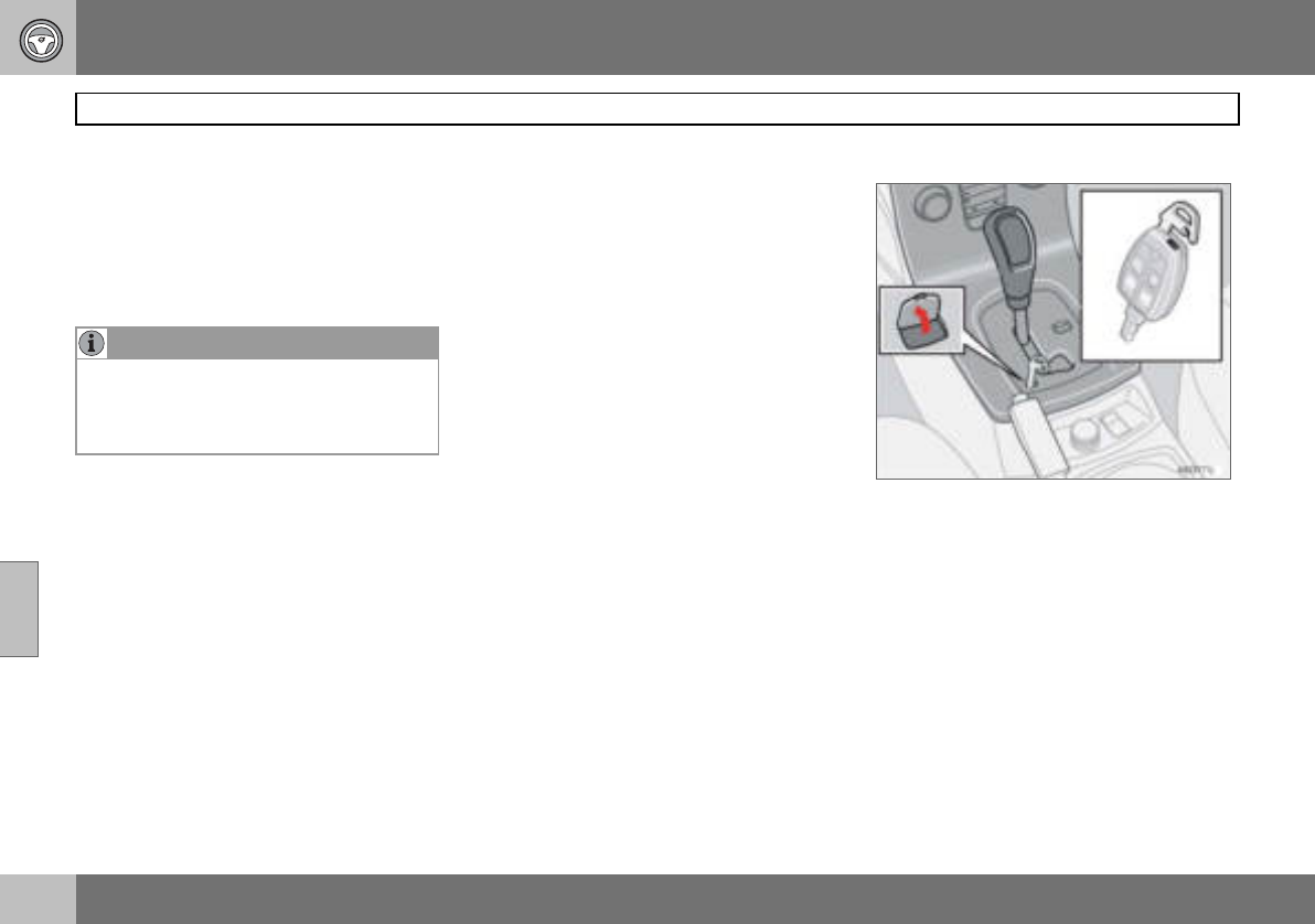
06 Starting and driving
116
Automatic gearbox
06
Cold start
When starting in low temperatures, the gear
changes can sometimes feel hard. This is
due to the gearbox oil’s viscosity at low tem-
peratures. To reduce engine emissions, the
gearbox shifts up later than normal when the
engine is started at low temperatures.
Kick-down
When the accelerator pedal is pressed all the
way to the floor, beyond the position normal-
ly regarded as full acceleration, a lower gear
is immediately engaged. This is known as
kick-down.
If the accelerator is released from the kick-
down position, the gearbox automatically
changes up.
Kick-down is used when maximum accelera-
tion is needed, such as for overtaking.
To prevent overrevving, the gearbox control
program has a protective downshift inhibitor
which prevents the kick-down function.
The kick-down function cannot be used in
manual gear position (Geartronic).
Safety systems
Cars with an automatic gearbox have special
safety systems:
Keylock
To remove the ignition key, the gear selector
must be in the P position. The key is locked
in all other positions.
Parking position (P position)
Stationary car with engine running:
– Hold your foot on the brake pedal when
moving the gear selector to another posi-
tion.
Electric gear inhibitor – Shiftlock
Parking position (P position)
To be able to move the gear selector from the
P position to other gear positions, the ignition
key must be in position II and the brake ped-
al must be depressed.
Shiftlock – Neutral (N position)
If the gear selector is in the N position and
the car has been stationary for at least three
seconds (irrespective of whether the engine
is running) then the gear selector is locked in
the N position.
To be able to move the gear selector from the
N position to another gear position, the brake
pedal must be depressed and the ignition
key must be in position II.
Disengaging shiftlock
In certain cases, it may be necessary to
move the car when it is not driveable, for ex-
ample if the battery is flat. Proceed as follows
to move the car:
1. There is a small cover below the P-R-N-D
text on the gear selector panel. Open it at
the rear edge.
2. Fully insert the key blade from the
remote control.
3. Hold the key blade down and at the
same time move the gear lever out of
the P position.
NOTE
Depending on the engine temperature when
the engine is started, the idle speed after a
cold start may be higher than normal for
certain engine types.
06 Starting and driving
117
Automatic gearbox
06
Mechanical gear selector inhibitor
The gear selector can be moved freely be-
tween N and D. Other positions are locked
with a latch that is released with the inhibitor
button on the gear selector.
The gear selector can be moved between the
different gear positions by pressing the inhib-
itor button.
Automatic gear positions
P – Parking position
Select position P when you wish to start the
engine or park the car.
The gearbox is mechanically blocked when
the P position is engaged. Always apply the
parking brake when parking the car.
R – Reverse
The car must be stationary when R is select-
ed.
N – Neutral
N is the neutral position. No gear is engaged
and the engine can be started. Apply the
parking brake when the car is stationary with
the gear selector in position N.
D – Drive
D is the normal driving position. Shifting up
and down between the different gearbox ra-
tios occurs automatically based on the level
of acceleration and speed. The car must be
stationary when the gear selector is moved to
position D from position R.
IMPORTANT
The car must be stationary when position P
is selected.
NOTE
The brake pedal must be depressed to
move the gear selector from the P position.
06 Starting and driving
118
Automatic gearbox
06
Manual positions
To move from the automatic driving
position D to a manual position, move the
gear selector to position M. To go from
position M to the automatic driving
position D, move the selector to position D.
While driving
The manual gearshift mode can be selected
at any time while driving. The engaged gear
is locked until you choose another gear.
If the gear selector is moved to – (minus) the
car changes down a gear and engine brakes
at the same time as the accelerator pedal is
released. If the gear selector is moved to
+ (plus) the car changes up a gear.
The selected gear is indicated on the com-
bined instrument panel, see page 39.
• Geartronic does not permit downshifting/
kick-down which would result in an engine
speed high enough to damage the engine.
Nothing happens if the driver tries to shift
down in this way. The original gear re-
mains engaged.
• Geartronic automatically shifts down if the
driver allows the speed to decrease lower
than a level suitable for the selected gear,
in order to avoid jerking and stalling.
W – Winter
The W button is used to ac-
tivate and deactivate the
winter program W. Display
of the W symbol in the
combined instrument panel
indicates that the winter
program is active.
The winter program starts the gearbox in a
higher gear to facilitate starting off on slip-
pery surfaces. The lower gears are only acti-
vated with kick-down when the winter pro-
gram is engaged.
The W program can be selected regardless
of the position of the gear selector, but is
only operational when the selector is in
position D.
To prevent overrevving, the gearbox control
program has a protective downshift inhibitor.
NOTE
Geartronic contains two safety functions:

06 Starting and driving
119
Brake system
06
Brake servo
If the car is rolling or is being towed with the
engine turned off, the brake pedal must be
pressed about five times harder than when
the engine is running. If the brake pedal is
depressed when the engine is started, you
will feel the pedal drop. This is normal and
due to the brake servo becoming active. This
may be more noticeable if the car has Emer-
gency Brake Assistance (EBA).
Brake circuits
This symbol lights if a brake circuit
is not working.
If a fault should occur in one of the
circuits, it is still possible to brake
the car. The brake pedal will travel further
and may feel softer than normal. Harder
pressure on the pedal is needed to produce
the normal braking effect.
Dampness can affect braking charac-
teristics
Brake components become wet when the
car is driven in heavy rain, through pools of
water or when the car is washed. This may
alter brake pad friction characteristics so that
there is a delay before braking effect is no-
ticed.
Press the brake pedal lightly from time to
time if driving for long stretches in rain or
slushy snow, as well as after setting off in
very damp or cold weather. This warms up
the brake pads and dries off any water. This
precaution is also recommended before
parking the car for a long period in such
weather conditions.
If the brakes are used heavily
When driving in the Alps or other roads with
similar characteristics, the car’s brakes are
heavily loaded even if the brake pedal is not
being depressed especially hard.
Because speed is often low, the brakes are
not cooled as effectively as when driving on
flat roads at higher speed.
So as not to overload the brakes, shift down
when driving downhill instead of using the
foot brake. Use the same gear driving down-
hill as you would use driving uphill. This uses
engine braking more efficiently so the foot
brake is only required for brief periods.
Bear in mind that driving with a trailer puts an
additional load on the car’s brakes.
Anti-lock braking system (ABS)
The anti-lock braking system (ABS)
prevents the wheels from locking
up during braking.
This means the ability to steer is
maintained and it is easier to swerve to avoid
a hazard for example.
After the engine has been started, the ABS
will perform a brief self-test at a speed of
about 20 km/h. This can be felt and heard as
pulses in the brake pedal.
To get the most out of the ABS:
1. Depress the brake pedal with full force.
Pulses will be felt.
2. Steer the car in the direction of travel.
Do not release the pressure on the
pedal.
Practice braking with the ABS system in a
traffic-free area and in different weather con-
ditions.
The ABS symbol illuminates for two seconds
if there was a fault in the ABS system when
the engine was last running.
WARNING
The brake servo only works when the en-
gine is running.
NOTE
If braking with the engine switched off,
press the brake pedal sharply once, not re-
peatedly.
06 Starting and driving
120
Brake system
06
Emergency brake assistance – EBA
(Emergency Brake Assistance) For sudden
braking, full-strength braking is provided in-
stantaneously. The EBA function senses
when heavy braking is underway by register-
ing how quickly the brake pedal is de-
pressed. Continue braking without easing off
on the brake pedal. The function is suspend-
ed when the pressure on the brake pedal
eases. This function is always active. It can-
not be disengaged.
WARNING
If the BRAKE and ABS warning symbols illu-
minate at the same time, there may be a
fault in the brake system. If the level in the
brake fluid reservoir is normal at this stage,
drive carefully to the nearest authorised
Volvo workshop and have the brake system
checked.
If the brake fluid is under the MIN level in the
brake fluid reservoir, do not drive further be-
fore topping up the brake fluid.
The reason for the loss of brake fluid must
be investigated.
NOTE
When EBA is activated the brake pedal low-
ers slightly more than usual, depress (hold)
the brake pedal as long as necessary. If the
brake pedal is released then all braking
ceases.
06 Starting and driving
121
Stability and traction control system
06
General
The Dynamic Stability and Traction Control
system (STC/DSTC) improves the car’s trac-
tion and helps the driver to avoid skidding.
A pulsing sound may be noticed during brak-
ing or acceleration when the system is in ac-
tion. The car may accelerate slower than ex-
pected when the accelerator pedal is de-
pressed.
The car is equipped with either STC or DSTC
depending on market. The table shows the
integral functions of the respective systems.
Active Yaw Control
The function limits the driving and brake
force of the wheels individually in order to
stabilise the car.
Spin Control
The function prevents the driving wheels
from spinning against the road surface dur-
ing acceleration.
Traction control system
The function is active at low speed and trans-
fers power from the driving wheel that is
spinning to the one that is not.
Reduced operation
The stability system is activated automatical-
ly each time the car is started.
System operation during skidding and accel-
eration can be partially deactivated.
Operation during skidding is delayed and so
allows more skidding which provides greater
freedom for dynamic driving.
Traction in deep snow or sand is improved as
acceleration is no longer limited.
Operation
– Turn thumbwheel (A) until the STC/ DSTC
menu is shown.
Function/system STC DSTC
Active Yaw Control X
Spin Control X X
Traction control system X X
06 Starting and driving
122
Stability and traction control system
06
DSTC ON means that the system function is
unchanged.
DSTC SPIN CONTROL OFF means that sys-
tem operation is reduced.
–Press and hold RESET (B) until the DSTC
menu is changed.
At the same time the symbol illuminates
as a reminder that the system has been re-
duced. The system remains reduced until the
engine is next started.
Messages in the information display
TRACTION CONTROL TEMPORARILY OFF
means that the system has been temporarily
reduced due to excessive brake disc temper-
ature.
The function is reactivated automatically
when the brakes have cooled.
ANTI-SKID SERVICE REQUIRED means that
the system has been disabled due to a fault.
– Stop the car in a safe place and turn off
the engine.
If the message remains when the engine is
restarted, drive to an authorised Volvo work-
shop.
Symbols in the combined instrument
panel
DSTC system
Information
If the symbols and are displayed at
the same time, read the message on the in-
formation display.
If the symbol appears alone then it may
appear as follows:
• Flashing light means that the STC/DSTC
system is now being activated.
• Constant glow for two seconds means
system check when the engine is started.
• Constant glow after starting the engine or
while driving means a STC/DSTC system
fault.
• Constant glow after deactivation reminds
that the STC/DSTC system has been re-
duced.
WARNING
Suppressing system function may alter the
driving characteristics of the car.
NOTE
DSTC ON is shown for several seconds in
the display and the symbol illuminates
each time the engine is started
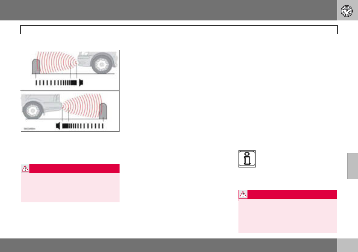
06 Starting and driving
123
Parking assistance (option)
06
General1
Parking assistance front and rear.
Parking assistance is used as an aid to park-
ing. A signal indicates the distance to a de-
tected object.
Function
The system is activated automatically when
the car is started and the text message Park
Assist active, Exit to deactivate is shown on
the audio system display.
Parking assistance is active at speeds below
15 km/h. The system is deactivated at higher
speeds. When the speed is below 10 km/h
the system is reactivated.
The frequency of the signal increases as you
come closer to an object in front of or behind
the car. If the volume of another audio source
from the audio system is high, then this is au-
tomatically lowered.
The tone becomes constant at a distance of
about 30 cm. If there are objects within this
distance both behind and in front of the car,
the signal alternates between left and right-
hand speakers.
Rear parking assistance
The distance covered to the rear of the car is
about 1.5 m. Rear parking assistance is acti-
vated when reverse gear is engaged. If the
system is switched off, the audio system dis-
play shows the text Park Assist deactivated
Enter to activate as soon as reverse gear is
engaged. The signal comes from the rear
loudspeakers.
The system must be deactivated when re-
versing with a trailer, or bike carrier on the
towbar or similar. Otherwise the trailer or bike
carrier would trigger the sensors.
Rear parking assistance is deactivated auto-
matically when towing a trailer if a Volvo gen-
uine trailer cable is used.
Front parking assistance
The distance covered to the front of the car is
about 0.8 metres. The signal comes from the
front loudspeakers.
Front parking assistance cannot be com-
bined with auxiliary lamps because the sen-
sors are affected by the auxiliary lamps.
Fault indicator
If the information symbol illumi-
nates with constant glow and
PARK ASSIST SERVICE RE-
QUIRED is shown on the informa-
tion display then parking assistance is disen-
gaged.
1Depending on the market, the Parking assist-
ance system may be either standard, an op-
tion or an accessory.
WARNING
Parking assistance does not relinquish the
driver’s own responsibility during parking.
The sensors have blind spots where objects
cannot be detected. Be aware of children or
animals near the car WARNING
Some sources may deceive the system with
false signals. Examples of such sources in-
clude horns, wet tyres on asphalt, pneumat-
ic brakes and motorcycle exhaust pipes
etc. Ice and snow covering the sensors may
also cause false warning signals.
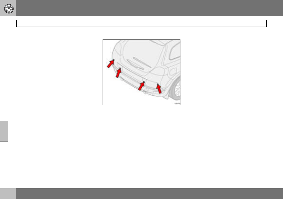
06 Starting and driving
124
Parking assistance (option)
06
Activating/deactivating
Parking assistance can be deactivated by
pressing EXIT on the control panel, see
page 64. Park Assist deactivated Enter to
activate will appear on the audio system dis-
play. Parking assistance can be reactivated
by pressing ENTER on the control panel. The
display then shows Park Assist active Exit
to deactivate.
Cleaning the sensors
Parking assistance sensors.
The sensors must be cleaned regularly to en-
sure that they work properly. Clean them with
water and car shampoo.
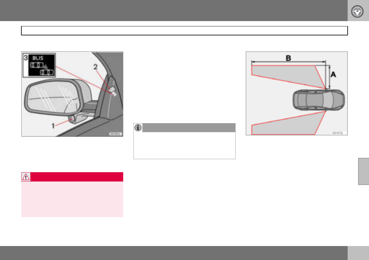
06 Starting and driving
125
Blind Spot Information System BLIS (option)
06
General
Rearview mirror with BLIS system.
1. BLIS camera
2. Indicator lamp
3. BLIS symbol
BLIS is an information system that under cer-
tain conditions can help to draw the driver’s
attention to vehicles moving in the same di-
rection in the so-called "blind spot".
The system is designed to work most effec-
tively when driving in dense traffic on multi-
lane highways.
BLIS is based on digital camera technology.
The cameras (1) are located under the door
mirrors.
When a camera has detected a vehicle inside
the blind spot zone the indicator lamp (2) illu-
minates with a constant glow.
BLIS advises the driver with a message if a
fault arises in the system. If for example the
system’s cameras are obscured then the
BLIS indicator lamp flashes and a message is
shown in the information display. In such
cases, check and clean the lenses. If neces-
sary, the system can be switched off tempo-
rarily by pressing the BLIS button, see
page 127.
Blind spots
"Blind spots" intended to be covered by BLIS
cameras.
Distance A = approx. 3.0 m
Distance B = approx. 9.5 m
Cleaning
In order to work most effectively the BLIS
camera lenses must be clean. The lenses can
be cleaned with a soft cloth or damp sponge.
WARNING
The system is a supplement to, not a re-
placement for, a safe driving style and use
of the rearview mirrors. It can never replace
the driver’s attention and responsibility. The
responsibility for changing lanes safely al-
ways rests with the driver.
NOTE
The lamp illuminates on the side of the car
where the system has detected the vehicle.
If the car is overtaken on both sides at the
same time then both lamps illuminate.
06 Starting and driving
126
Blind Spot Information System BLIS (option)
06
Clean the lenses carefully so that they are not
scratched.
When BLIS operates
The system is active when the car is driven at
a speed above 10 km/h.
Overtaking
The system is designed to react if you over-
take at a speed of up to 10 km/h faster than
the overtaken vehicle.
The system is designed to react if you are
overtaken by a vehicle travelling up to 70 km/
h faster than your vehicle.
Daylight and darkness
In daylight the system reacts to the shape of
the surrounding vehicles. The system is de-
signed to detect motor vehicles such as cars,
trucks, buses and motorcycles.
In darkness the system reacts to the head-
lamps of surrounding vehicles. Vehicles with
headlamps that are switched off are not de-
tected by the system. This means for exam-
ple that the system does not react to a trailer
without headlamps which is towed behind a
car or truck.
IMPORTANT
The lenses are electrically heated to melt ice
or snow. If necessary, brush snow away
from the lenses.
WARNING
BLIS does not work in sharp bends.
BLIS does not work when the car is revers-
ing.
A wide trailer coupled to the car can con-
ceal other vehicles in adjacent lanes. It can
prevent the vehicle in the screened area
from being detected by BLIS.
WARNING
The system does not react to bicycles or
mopeds.
The BLIS cameras can be disrupted by in-
tensive light or when driving in the dark
when there are no light sources (e.g. street
lighting or other vehicles). The system may
then interpret the lack of light as if the cam-
eras have been blocked.
In both cases a message is shown on the
information display.
When driving in such conditions system
performance may be temporarily reduced
and a text message is shown, see
page 127.
If the message disappears automatically
then BLIS has returned to normal function-
ality.
The BLIS cameras have limitations similar
to the human eye, i.e. they "see" worse in
heavy snowfall or thick fog for example.
06 Starting and driving
127
Blind Spot Information System BLIS (option)
06
Activating/deactivating
Button for activating/deactivating.
BLIS is activated when the engine is started.
The indicator lamps in the door panels flash
three times when BLIS is activated.
The system can be deactivated/activated by
pressing BLIS.
When BLIS is deactivated the light in the but-
ton goes out and a text message is shown on
the dashboard display.
When BLIS is activated the light in the button
illuminates, a new text message is shown on
the display and the indicator lamps in the
door panels flash three times. Press the
READ button to clear the text message. For
more information on messages, see page 43.
BLIS system message
Te xt o n t he
display System status
BLIND SPOT
SYST. SERVICE
REQUIRED
Blind spot syst. disen-
gaged. Contact an
authorised Volvo
workshop.
BLIS FUNCTION
REDUCED
Reduced function.
BLIS CAMERA
BLOCKED
One or both cameras
blocked.
Clean the lenses.
Blind spot syst.
OFF
BLIS system off.
Blind spot syst.
ON
BLIS system on.
06 Starting and driving
128
Towing and recovery
06
Never tow the car to bump start it
Use a donor battery if the battery is dis-
charged and the engine does not start. Do
not tow the car to bump start it.
To w i n g
Find out the highest legal speed for towing
before towing the car.
– Turn the ignition switch to position II and
unlock the steering lock so that the car
can be steered, see page 112.
– The ignition key must remain in position II
while the car is being towed.
Automatic gearbox
– Move the gear selector to position N.
Manual gearbox
– Move gear lever into neutral.
– Ensure the towrope is always taut to avoid
violent jerks. Keep your foot on the brake
pedal.
Cars with automatic gearbox must not be
towed at speeds above 80 km/h or further
than 80 km. The car must always be towed
facing forward.
Recovery
If only partially raised, cars with automatic
gearbox must not be transported at speeds
above 80 km/h or further than 80 km. The car
must always be towed with the wheels rolling
forward.
Tow i n g e y e
Use the towing eye if the car needs to be
towed on the road. The towing eye is at-
tached in the recess on the right-hand side of
the front or rear bumper. To fit the towing
eye:
1. Take out the towing eye that is located
under the floor hatch in the cargo area.
IMPORTANT
Bump starting the car can damage the cata-
lytic converter.
WARNING
The steering lock stays in the position it was
in when the power was cut off. The steering
lock must be unlocked before towing.
The ignition key must be in position II.
Never remove the ignition key from the igni-
tion switch while driving or when the car is
being towed.
WARNING
The brake servo and power steering do not
work when the engine is switched off. The
brake pedal must be pressed about five
times harder than normal, and the steering
will be considerably heavier than normal.
06 Starting and driving
129
Towing and recovery
06
2. Release the cover (1) on the bumper
with a screwdriver or coin in the bottom
edge.
3. Screw in the towing eye (3) firmly, right
up to the flange. Use the wheel wrench
to tighten the towing eye.
4. After use, unscrew the towing eye and
return it in the cargo area. Refit the
cover on the bumper.
IMPORTANT
The towing eye is only designed for towing
on roads, not for pulling the car unstuck or
out of a ditch. Call a recovery service for re-
covery assistance.
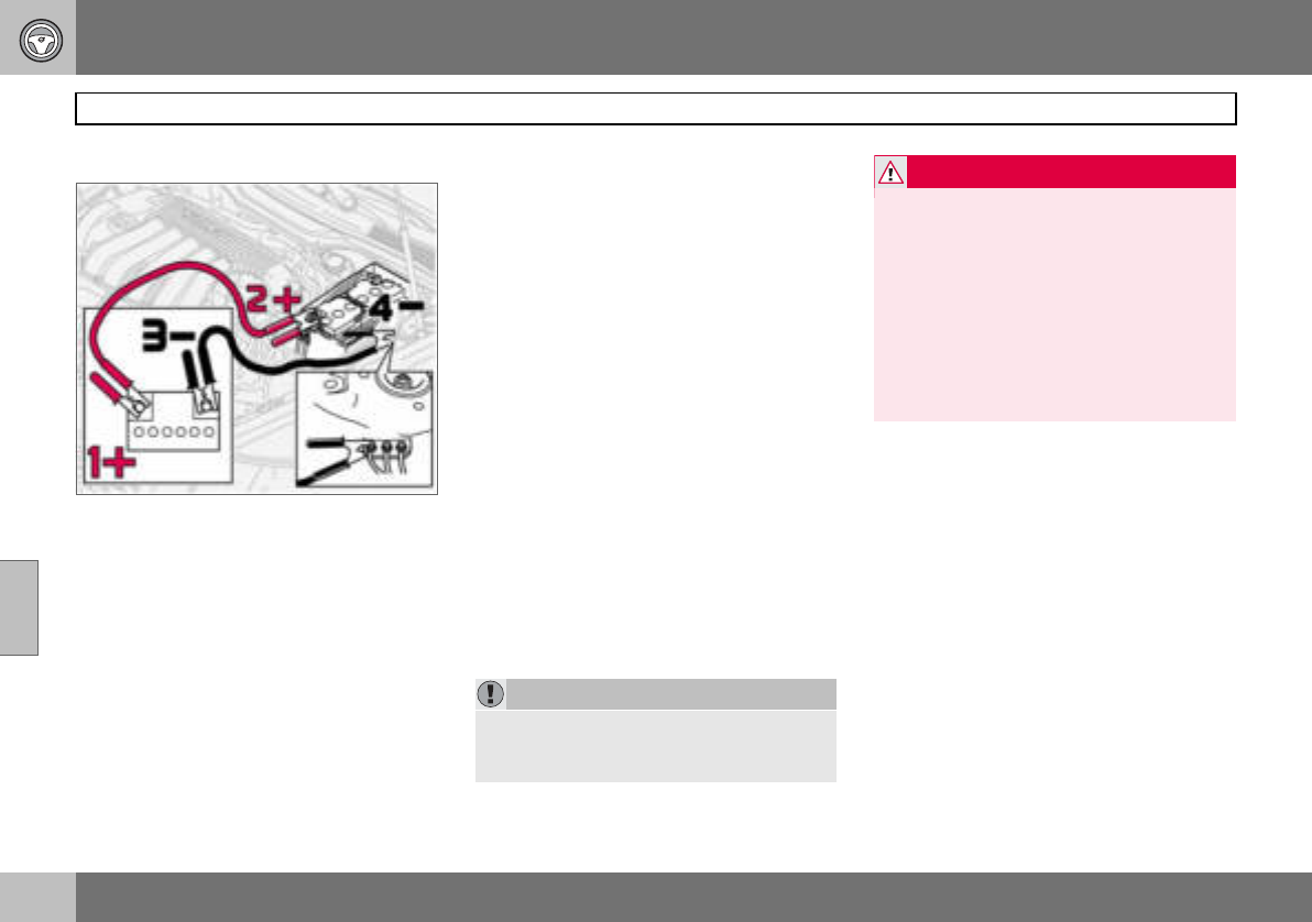
06 Starting and driving
130
Jump starting
06
Starting with a donor battery
If the battery in the car has become flat, you
can "borrow" electric current from either a
separate battery or the battery in another car.
Always make sure the crocodile clips on the
jump leads are attached securely to eliminate
sparks during the start attempt.
When jump starting the car, the following
steps are recommended to avoid risk of ex-
plosion:
1. Turn the ignition key to position 0.
2. Ensure that the donor battery is 12 volt.
3. If the donor battery is in another car,
switch off the engine in the other car
and ensure that the cars do not touch
one another.
4. Connect the red jump lead between the
positive terminal on the donor battery
(1+) and the positive terminal in your
car (2+).
5. Connect one end of the black jump
lead to the donor battery’s negative
terminal (3–).
6. Connect the other end of the black
jump lead to the earthing point (4–) by
the left-hand strut tower.
7. Start the engine of the "donor car". Let
the engine run a few minutes at a speed
slightly higher than idle (1500 rpm).
8. Start the engine of the car with the flat
battery.
9. Remove the jump leads, first the black
and then the red. Make sure that none
of the clamps on the black jump lead
comes into contact with the battery’s
positive terminal or the clamp connect-
ed to the red jump lead.
IMPORTANT
Do not touch the crocodile clips during the
start procedure. There is a risk of sparks
forming.
WARNING
The battery can generate oxyhydrogen gas,
which is highly explosive. One spark, which
can be generated if you connect the jump
leads incorrectly, is sufficient to make the
battery explode.
The battery contains sulphuric acid, which
can cause serious burns. If the acid comes
into contact with eyes, skin or clothing,
flush with large quantities of water.
If acid splashes into the eyes, seek medical
attention immediately.
06 Starting and driving
131
Driving with a trailer
06
General
The load capacity is affected by extra acces-
sories mounted on the car, such as a towbar,
load carriers, space box, the passengers’
combined weight etc. as well as the load on
the towball. The load capacity of the car is
reduced by the number of passengers and
their weight.
If the towing bracket is fitted by an author-
ised Volvo workshop, then the car is deliv-
ered with the necessary equipment for driv-
ing with a trailer.
• The car’s towing bracket must be of an
approved type.
• If the towbar is retrofitted, check with your
Volvo dealer that the car is fully equipped
for driving with a trailer.
• Distribute the load on the trailer so that the
weight on the towing bracket follows the
specified maximum towball load.
• Increase the tyre pressure to the recom-
mended pressure for a full load. Tyre
pressure label location, see page 149.
• Clean the towbar regularly and grease the
towball1.
• Do not tow a heavy trailer when the car is
brand new. Wait until it has been driven at
least 1000 km.
• The brakes are loaded much more than
usual on long and steep downhill slopes.
Downshift to a lower gear and adjust your
speed.
• The engine is loaded more heavily than
usual when driving with a trailer.
• The engine and gearbox can overheat if
the car is driven with a heavy load in hot
weather. If the temperature gauge for the
engine’s cooling system goes into the red
zone, stop and let the engine idle for a few
minutes. The automatic gearbox responds
through a built-in protection system. See
the message on the information display. If
the car overheats, the air conditioning may
be switched off temporarily.
• In the interests of safety, speed should be
restricted to 80 km/h, even if the laws of
certain countries allow for higher speeds.
• Move the gear selector to park position P
when parking an automatic car with a
hitched trailer. Always use the parking
brake. Block the wheels with chocks when
parking a car with hitched trailer on a hill.
Trailer weights
Information on permitted trailer weights, see
page 222.
1Does not apply to the towball if using a stabi-
liser hitch.
WARNING
Follow the stated recommendations for
trailer weights. Otherwise, the car and trailer
may be difficult to control in the event of
sudden movement and braking.
NOTE
The stated maximum permitted trailer
weights are those permitted by Volvo. Na-
tional vehicle regulations can further limit
trailer weights and speeds. Towbars can be
certified for higher towing weights than the
car can actually tow.

06 Starting and driving
132
Driving with a trailer
06
Automatic gearbox, driving with a
trailer
Parking on a hill
1. Apply the parking brake (handbrake).
2. Move the gear selector to park
position P.
Starting on a hill
1. Move the gear selector to driving
position D.
2. Release the parking brake (handbrake).
Steep inclines
• Select an appropriate manual gear posi-
tion when climbing steep inclines or at low
speeds. This prevents the gearbox from
changing up and keeps the gearbox oil
cooler.
• Do not use a higher manual gear than the
engine can handle. It is not always eco-
nomical to drive in high gears.
• Avoid driving with a trailer on inclines of
more than 15 %.
Diesel 1.6D engine with manual
gearbox, driving with a trailer
If the car is driven with a major load in a hot
climate, the engine cooling fan can be re-
placed with one of a greater capacity than
the standard model. Check with your nearest
Volvo dealer regarding the options for your
car.
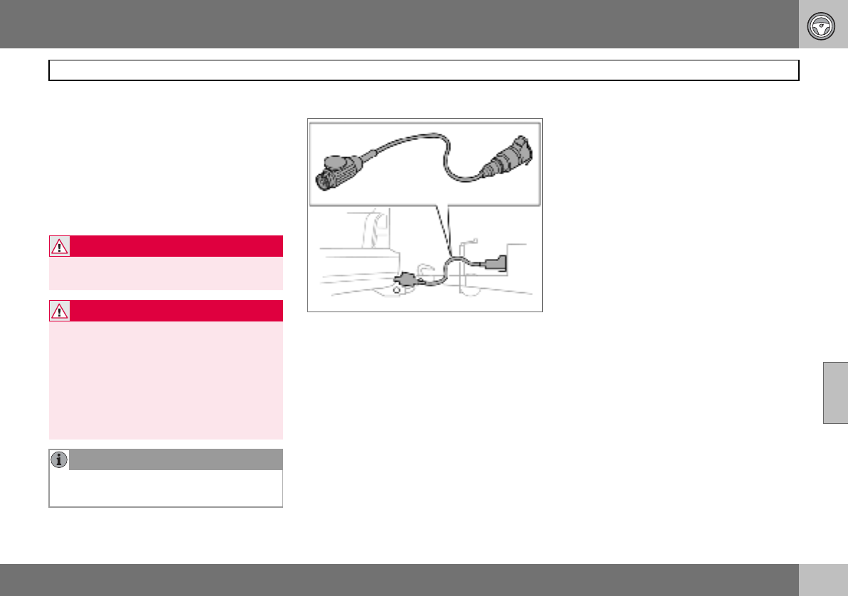
06 Starting and driving
133
Towing bracket
06
To wb a r s
The towball must be cleaned and greased
regularly. When a towball hitch with vibration
damper is used, the towball need not be
greased.
If the car is equipped with a detachable tow-
bar, the towball mounting instructions must
be followed carefully, see page 135.
Trailer cable
An adapter is required if the car’s towing
bracket has 13 pin electrics and the trailer
has 7 pin electrics. Use an adapter cable ap-
proved by Volvo. Make sure the cable does
not drag on the ground.
WARNING
Be sure to attach the trailer’s safety cable to
the correct place.
WARNING
If the car is fitted with a Volvo detachable
towbar:
Follow the assembly instructions for the
towball section carefully.
The towball section must be locked with the
key before setting off.
Check that the indicator window shows
green.
NOTE
Always detach the towball section after use.
Keep it in the cargo area.
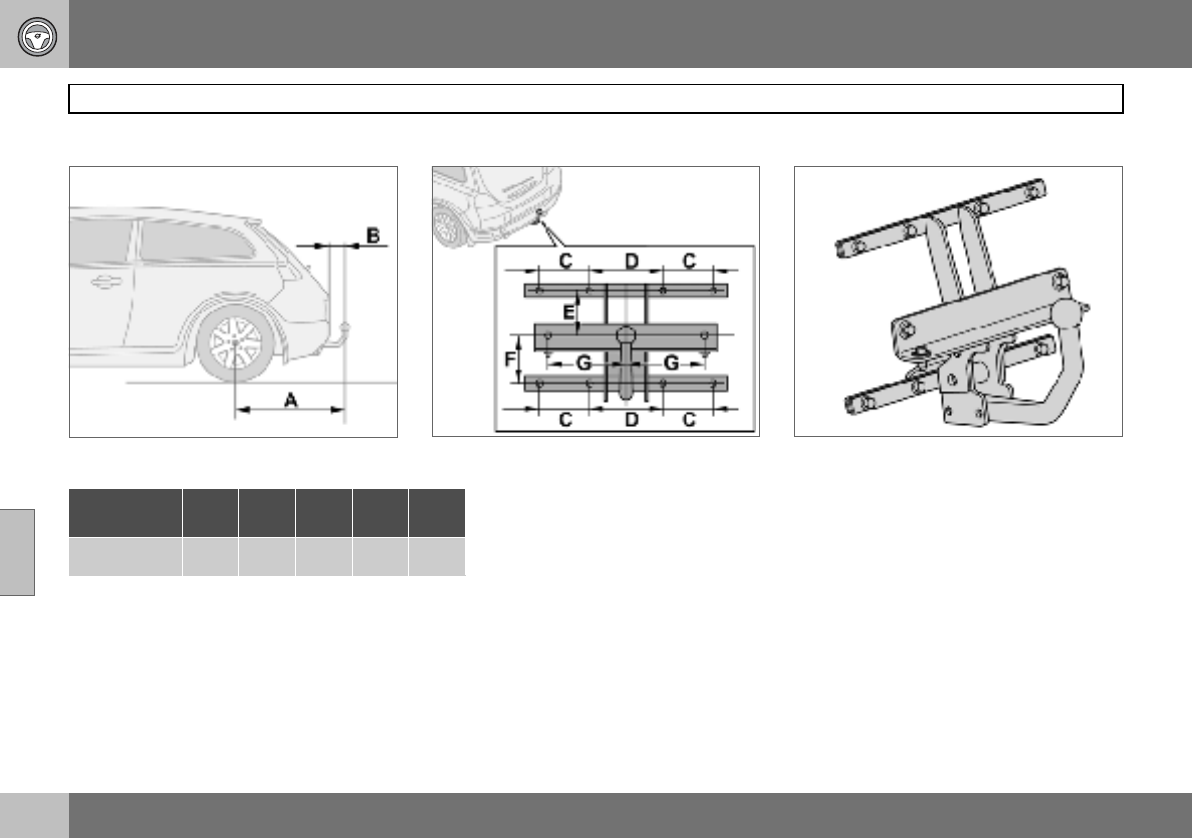
06 Starting and driving
134
Towing bracket
06
Specifications
Dimensions for mounting points (mm)
A B C D E F G
852 98 100 140 130 113 150
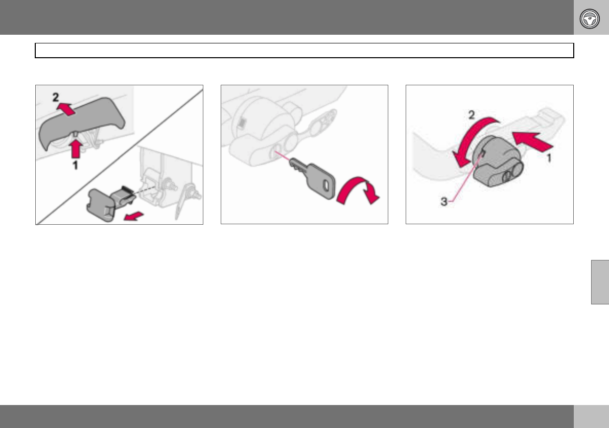
06 Starting and driving
135
Detachable towbar
06
Fitting the towball
– Remove the guard plug. – Ensure that the mechanism is in the un-
locked position by turning the key clock-
wise.
– Check that the indicator window (3) shows
red. If the window does not show red,
press in (1) and turn the locking wheel
anticlockwise (2) until you hear a click.
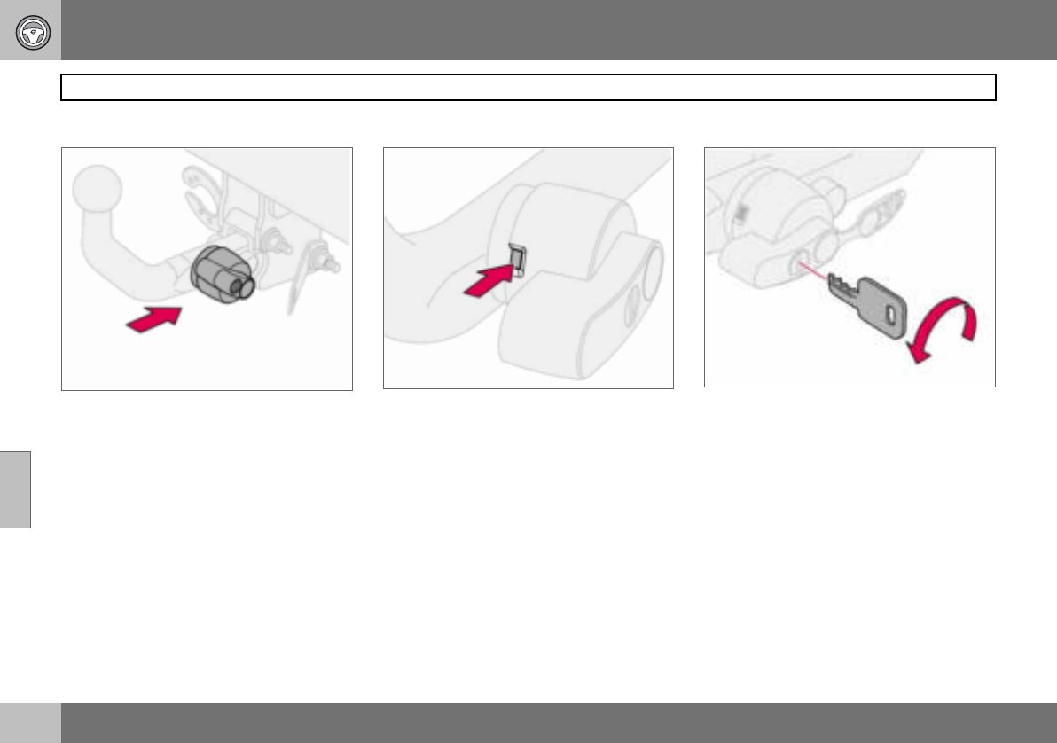
06 Starting and driving
136
Detachable towbar
06
– Insert the towball section until you hear a
click.
– Check that the indicator window shows
green.
– Turn the key anticlockwise to locked posi-
tion. Remove the key from the lock.
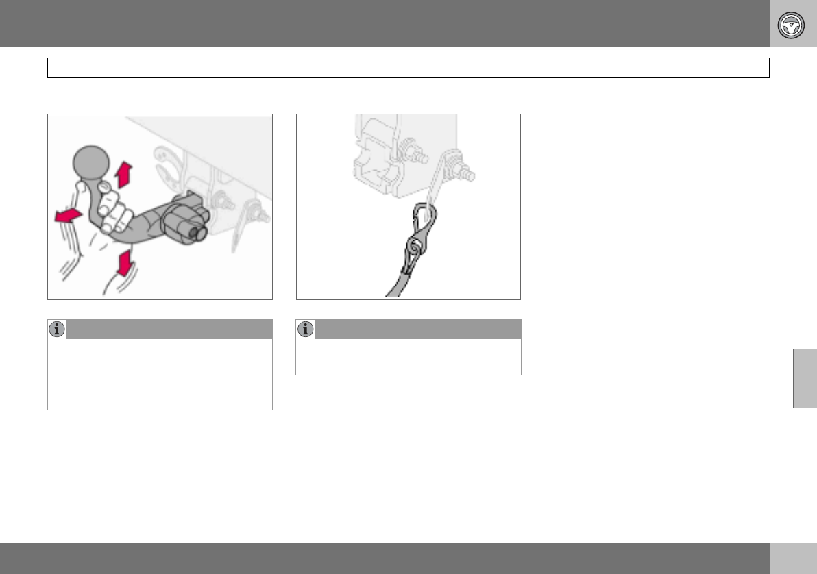
06 Starting and driving
137
Detachable towbar
06
NOTE
Check that the towball section is secure by
pulling it up, down and back. If the towball
section is not fitted correctly then it must be
removed and refitted in accordance with
the previous instruction.
NOTE
The trailer’s safety cable must be attached
to the bracket on the towbar.
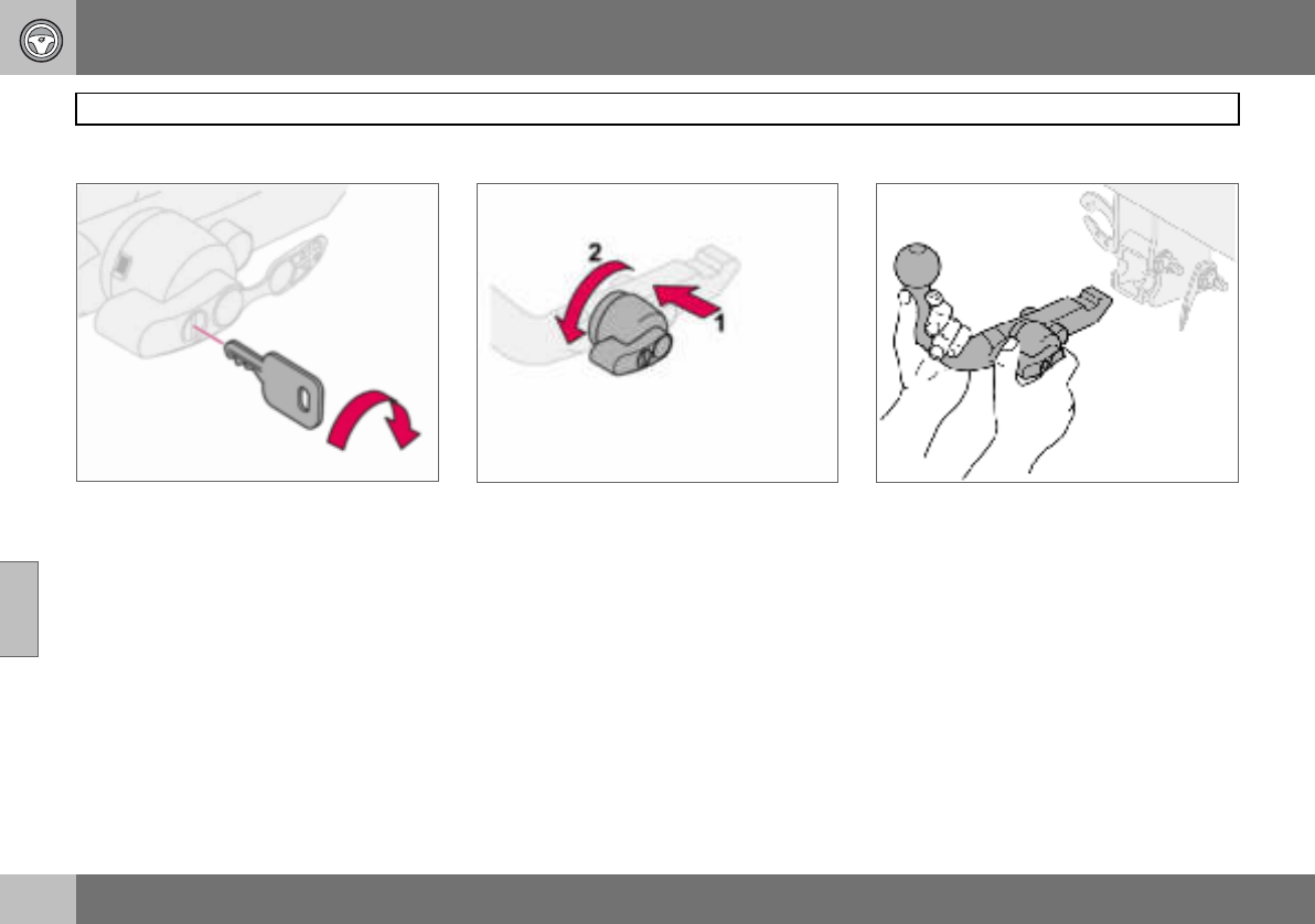
06 Starting and driving
138
Detachable towbar
06
Removing the towball
– Insert the key and turn it clockwise to the
unlocked position.
– Push in the locking wheel (1) and turn it
anticlockwise (2) until you hear a click.
– Turn the locking wheel down fully, until it
comes to a stop. Hold it in this position
while pulling the towball rearward and
upward.
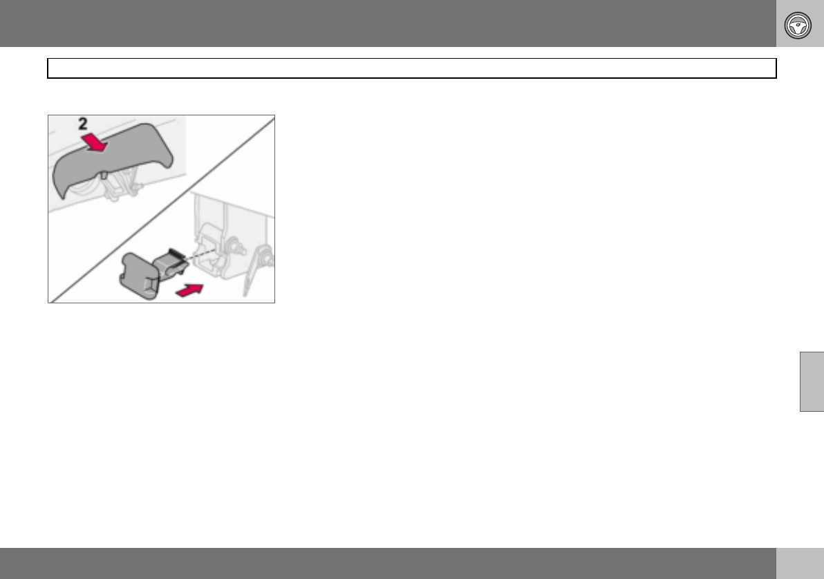
06 Starting and driving
139
Detachable towbar
06
– Insert the guard plug.
06 Starting and driving
140
Loading
06
General
The load capacity is affected by extra acces-
sories mounted on the car, such as a towbar,
the load on the towball, load carriers and
space box, and the passengers’ combined
weight. The load capacity of the car is re-
duced by the number of passengers and
their weight. For information on permitted
weights, see page 222.
Loading the cargo area
Stop the engine and apply the parking brake
when loading or unloading long objects. The
gear lever or gear selector can be knocked
out of position by long loads, which could set
the car in motion.
To increase the size of the cargo area, the
head restraints can be removed and the
seats folded down, see page 86.
Place the load firmly against the backrest in
front.
• The head restraints can be removed so
that they are not damaged.
• Put wide loads in the centre.
• Heavy objects should be placed as low as
possible. Avoid placing heavy loads on a
lowered backrest.
• Cover sharp edges with something soft to
avoid damaging the upholstery or the
large glass surface of the tailgate.
• Secure all loads to the load retaining eye-
lets with straps or web lashings.
Using load carriers
To avoid damaging the car and for maximum
possible safety while driving, it is recom-
mended to use load carriers specially de-
signed for your car by Volvo.
Carefully follow the mounting instructions
supplied with the load carriers.
• Check periodically that the load carriers
and load are properly secured. Lash the
load securely with retaining straps.
• Distribute the load evenly over the load
carriers. Put the heaviest objects at the
bottom.
• The size of the area exposed to the wind,
and therefore fuel consumption, increase
with the size of the load.
• Drive gently. Avoid quick acceleration,
heavy braking and hard cornering.
WARNING
The car’s driving characteristics change de-
pending on how heavily it is loaded and how
the load is distributed.
WARNING
A loose object weighing 20 kg can, in a
frontal collision at a speed of 50 km/h, carry
the impact of an item weighing 1000 kg.
WARNING
Never load cargo above the backrest.
The protection provided by the inflatable
curtain in the headlining may be compro-
mised or eliminated if the load is too high.
Always secure the load. During heavy brak-
ing the load may otherwise shift, causing in-
jury to the car’s occupants.
WARNING
The car’s centre of gravity and driving char-
acteristics are altered by roof loads.
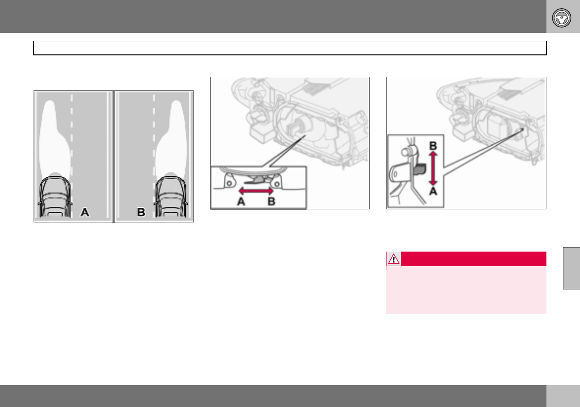
06 Starting and driving
141
Adjusting headlamp pattern
06
Correct light pattern for left or right-
hand traffic
A. Headlamp pattern for left-hand traffic.
B. Right-hand traffic.
The headlamps’ projection can be adjusted
to avoid dazzling oncoming traffic. The cor-
rect pattern will also better illuminate the
verge.
Halogen headlamps
The headlamp control should be in
position (A) for left-hand traffic and
position (B) for right-hand traffic.
Bi-Xenon headlamps
The headlamp control should be in
position (A) for left-hand traffic and
position (B) for right-hand traffic.
WARNING
On cars with Bi-Xenon headlamps, their re-
placement must be carried out by an au-
thorised Volvo workshop. The headlamps
must be handled with extreme care due to
the high-voltage unit in the Xenon lamp.

142
General ................................................................................................... 144
Tyre pressure .......................................................................................... 148
Warning triangle and spare wheel .......................................................... 150
Changing wheels .................................................................................... 151
Emergency puncture repair ....................................................................153
07
WHEELS AND TYRES
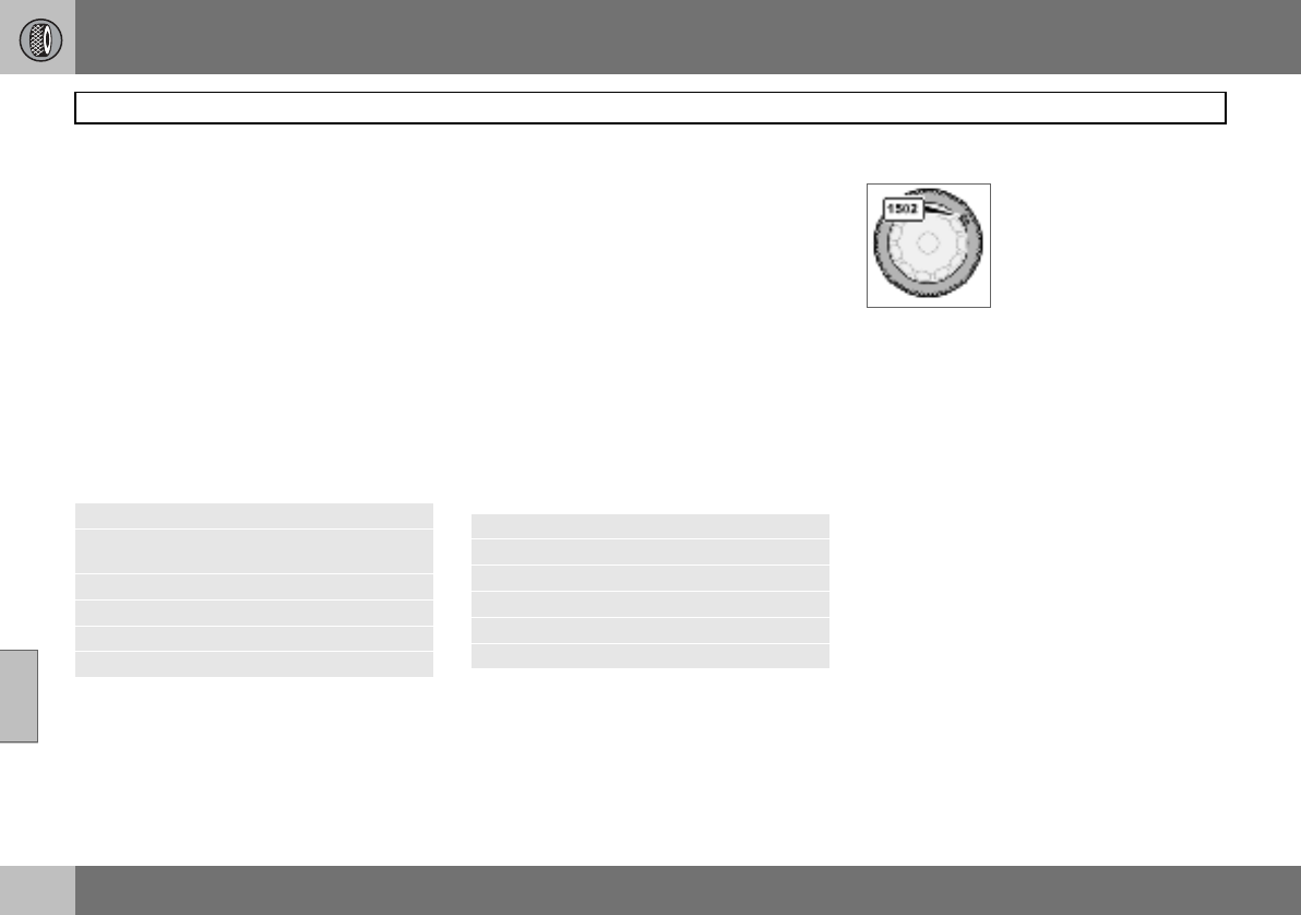
07 Wheels and tyres
144
General
07
Driving characteristics and tyres
The tyres greatly affect the car’s driving char-
acteristics. The type of tyre, dimensions, tyre
pressure and speed rating are important for
how the car performs.
When changing tyres, ensure that tyres of the
same type and dimensions, and preferably
also the same make, are fitted to all four
wheels. Follow the recommended tyre pres-
sures specified on the tyre pressure label, for
location see page 148.
Designation of dimensions
The dimensions are stated on all car tyres.
Example of designation: 205/55R16 91 W.
Speed ratings
The car is approved as a whole, which means
that dimensions and speed ratings must not
differ from those specified on the vehicle reg-
istration document. The only exception to
these conditions is winter tyres (both those
with metal studs and those without). If such a
tyre is chosen, the car must not be driven
faster than the speed rating of the tyre (for
example, class Q can be driven at a maxi-
mum of 160 km/h).
Remember that traffic regulations determine
how fast a car can be driven, not the speed
rating of the tyres.
Note! Maximum permitted speeds indicated.
New tyres
Tyres are perishable. After a
few years they begin to
harden at the same time as
the friction capacity/char-
acteristics gradually deteri-
orate. For this reason, aim
to get as fresh tyres as pos-
sible when you replace them. This is espe-
cially important with regard to winter tyres.
The week and year of manufacture, the tyre’s
DOT marking (Department of Transportation),
are stated with four digits, for example 1502.
The tyre in the illustration was manufactured
in week 15 of 2002.
Tyre age
All tyres older than six years should be
checked by an expert even if they seem un-
damaged. The reason for this is that tyres
age and decompose, even if they are hardly
ever or never used. The function can there-
fore be affected due to the tyre’s constituent
materials being broken down. The tyre
should then not be used. This also applies to
spare tyres, winter tyres and tyres saved for
future use. Examples of external signs which
indicate that the tyre is unsuitable for use are
cracks or discoloration.
The age of the tyre can be determined by the
DOT marking, see illustration above.
205 Section width (mm)
55 Ratio between section height and
width (%)
RRadial ply
16 Rim diameter in inches (")
91 Tyre load index (in this case 615 kg)
WSpeed rating (in this case 270 km/h).
Q160 km/h (used only on winter tyres)
T190 km/h
H210 km/h
V240 km/h
W270 km/h
Y300 km/h
07 Wheels and tyres
145
General
07
More even wear and maintenance
The correct tyre pressure results in more
even wear, see page 149. To achieve the
best traction and more even wear on the
tyres, the regular switching of the front and
rear tyres with each other is recommended.
The first change should be after 5000 km and
then at intervals of 10000 km, this is to avoid
differences in tread depth. Tyres with the
greatest tread depth should always be fitted
to the rear wheels to decrease the risk of
skidding. Contact an authorised Volvo work-
shop if you are uncertain about tread depth.
Wheels should be stored lying down or hang-
ing up, and not standing up.
Tyres with tread wear indicators
Tread wear indicators are narrow treadless
bands across the width of the tread. On the
side of the tyre are the letters TWI (Tread
Wear Indicator). When the tyre’s tread depth
is down to 1.6 mm, the tread depth will be
level in height with the tread wear indicators.
Change to new tyres as soon as possible.
Remember that tyres with little tread depth
provide very poor grip in rain and snow.
Winter tyres
Volvo recommends winter tyres with specific
winter tyre dimensions. These are stated on
the tyre pressure label, for location see
page 148. The tyre dimensions are depend-
ent on the engine variant. When driving on
winter tyres, they must be fitted to all four
wheels.
Studded tyres
Studded winter tyres should be run in gently
for 500–1000 km so the studs settle properly
into the tyres. This gives the tyre, and espe-
cially the studs, a longer service life.
Tread depth
Road conditions with ice, slush and low tem-
peratures place considerably higher de-
mands on tyres than summer conditions. It is
therefore recommended not to drive on win-
ter tyres that have a tread depth of less than
four millimetres.
Snow chains
Snow chains may only be used on the front
wheels, also applies to all-wheel drive cars.
Never drive faster than 50 km/h with snow
chains. Avoid driving on bare ground as this
wears out both the snow chains and tyres.
Never use quick-fit snow chains as the space
between the brake disks and the wheels is
too small.
NOTE
Ask a Volvo dealer which rim and tyre types
are most suitable.
NOTE
The legal provisions for the use of studded
tyres vary from country to country.
IMPORTANT
Use Volvo genuine snow chains or equiva-
lent chains designed for the car model, and
tyre and rim dimensions. Consult an author-
ised Volvo workshop
07 Wheels and tyres
146
General
07
Rims and wheel nuts
Standard (1) and bulge acorn (2) wheel nuts
Only use rims that are tested and approved
by Volvo and which are included in the Volvo
genuine accessories range. There are two
types of wheel nut, depending on whether
the rims are made of steel or aluminium.
Tighten the wheel nuts to 90 Nm. Check the
torque with a torque wrench.
Steel rims – standard wheel nuts (1)
Steel rims are normally mounted with the
standard wheel nuts, but the bulge acorn va-
riety may also be used.
Aluminium rims – bulge acorn wheel
nuts (2)
Only use the bulge acorn variety of nuts with
aluminium rims. These differ markedly from
other nut types as they have a rotating coni-
cal washer.
Locking wheel nuts
Locking wheel nuts can be used on both alu-
minium and steel rims. If steel rims with lock-
ing wheel nuts are used in combination with
wheel covers, the locking wheel nut should
be mounted on the bolt nearest the air valve.
Otherwise the wheel cover cannot be fitted to
the rim.
Spare wheel Temporary Spare
The spare wheel1 is only intended to be used
for the short time it takes to get the ordinary
wheel replaced or repaired. Replace the
spare wheel with a normal wheel as soon as
possible. The car’s handling may be altered
by the use of the spare wheel.
Never drive faster than 80 km/h with a spare
wheel on the car.
IMPORTANT
The wheel nuts should be tightened to
90 Nm. Overtightening can damage the
nuts and the bolts.
WARNING
Never use standard nuts for aluminium
rims. The wheel could come loose.
NOTE
These nuts may also be used with steel
rims.
1Certain variants and markets.
IMPORTANT
The car must never be driven fitted with
more than one "Temporary Spare" wheel.
07 Wheels and tyres
147
General
07
Summer and winter wheels
The arrow shows the tyre’s direction of rotation
When summer and winter wheels are
changed the wheels should be marked with
which side of the car they were mounted on,
for example L for left and R for right. Tyres
with a tread pattern which are designed to
only turn in one direction have the direction
of rotation marked with an arrow. The tyre
must always rotate in the same direction
throughout its lifespan. Tyres should only be
switched between front and rear positions,
never between left and right-hand sides, or
vice versa. If the tyre is mounted incorrectly,
the car’s braking characteristics and capaci-
ty to force rain, snow and slush out of the
way are adversely affected. Tyres with the
greatest tread depth should always be fitted
to the rear of the car (to decrease the risk of
skidding).
Wheels should be stored lying down or hang-
ing up, and not standing up.
Contact an authorised Volvo workshop if you
are uncertain about tread depth.
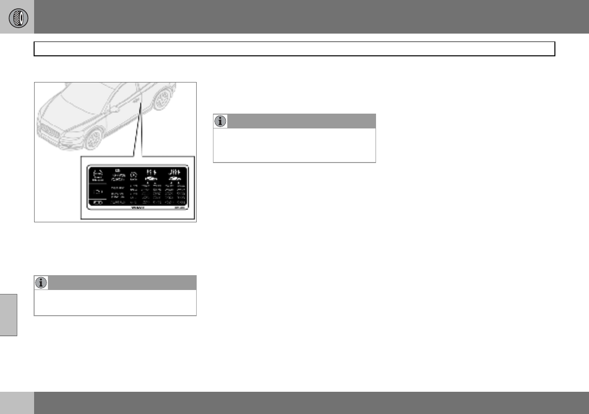
07 Wheels and tyres
148
Tyre pressure
07
Recommended tyre pressure
The tyre pressure label on the driver’s side
door pillar shows which pressures the tyres
should have at different loads and speed
conditions.
Stated on the decal:
• Tyre pressure for the car’s recommended
wheel dimension
• ECO pressure
• Spare wheel pressure (Temporary Spare).
Checking the tyre pressure
Check the tyre pressure regularly.
Even after several kilometres of driving, the
tyres warm up and the pressure increases.
So air must not be released if the pressure is
checked when the tyres are warm. While the
pressure must be increased if it is too low. In-
adequately inflated tyres adversely affect fuel
consumption, tyre lifespan and the car’s
roadholding. Driving on tyres with tyre pres-
sure that is too low can also result in the tyres
overheating and disintegrating.
For information on the correct tyre pressure,
refer to the tyre pressure table on page 149.
("Cold tyres" means the tyres are the same
temperature as the ambient temperature.)
Fuel economy, ECO pressure
At speeds under 160 km/h, the general tyre
pressure for full load is recommended in or-
der to obtain optimum fuel economy.
Tyre pressure affects travelling comfort, road
noise and steering characteristics.
NOTE
Full load in the car equates to the number of
seats with seatbelts.
NOTE
Tyre pressure decreases over time, this is a
natural phenomenon. Tyre pressure also
varies depending on ambient temperature.
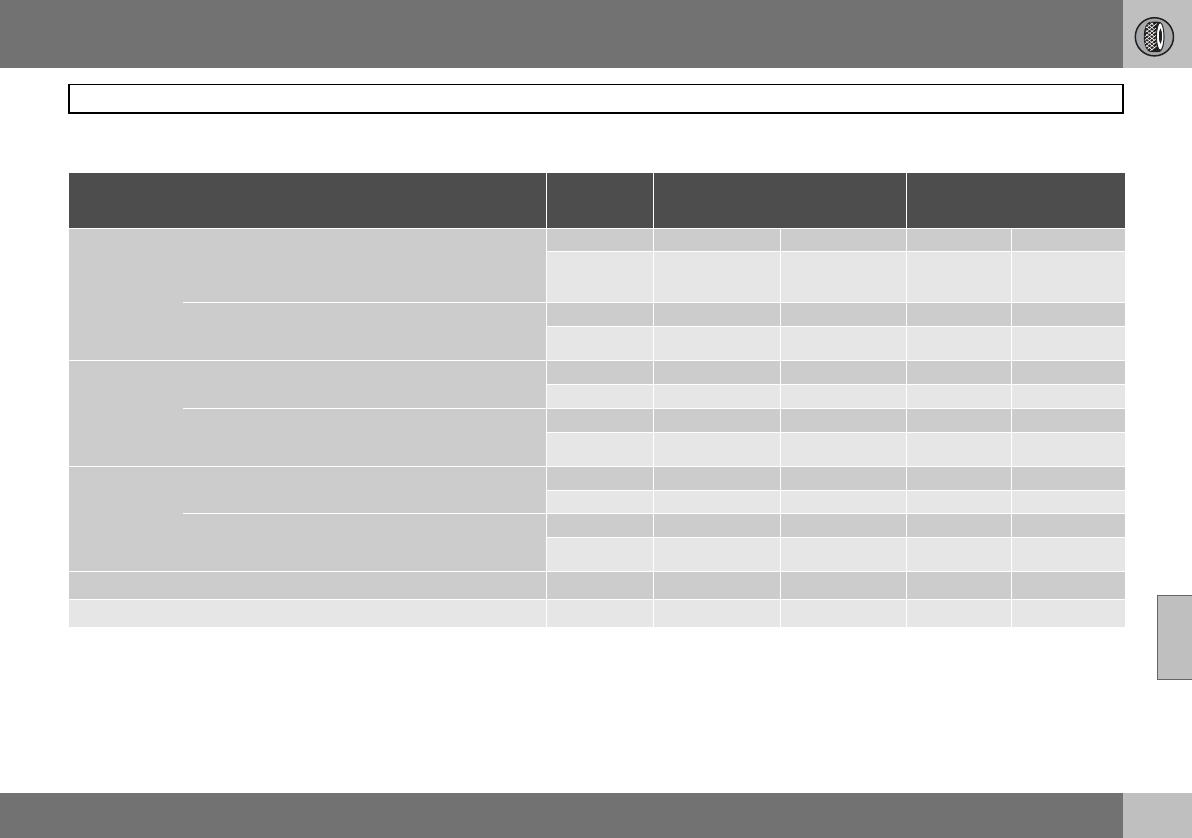
07 Wheels and tyres
149
Tyre pressure
07
Tyre pressure table
Variant Tyre size Speed
(km/h)
Load, 1-3 persons
Front (kPa) Rear (kPa)
Max. load
Front (kPa) Rear (kPa)
1.6
1.8
1.8F
2.0
1.6D
195/65 R15 91V
205/55 R16 91V/W
195/65 R15 91Q/T/H/V M+S
205/55 R16 91Q/T/H/V M+S
0 –160 230 210 250 250
160+ 250 210 280 260
205/50 R17 93W Extra Load
215/45 R18 93W Extra Load
205/50 R17 93Q/T/H/V M+S Extra Load
0–160 240 220 250 250
160 + 260 220 280 260
2.4
2.4i
2.0D
205/55 R16 91V/W
205/55 R16 91Q/T/H/V M+S 0–160 230 210 250 250
160+ 250 210 280 260
205/50 R17 93W Extra Load
215/45 R18 93W Extra Load
205/50 R17 93Q/T/H/V M+S Extra Load
0–160 240 220 250 250
160+ 260 220 280 260
T5
D5 205/55 R16 91 V/W
205/55 R16 91Q/T/H/V M+S 0–160 230 210 250 250
160+ 260 210 280 260
205/50 R17 93W Extra Load
215/45 R18 93W Extra Load
205/50 R17 93Q/T/H/V M+S Extra Load
0–160 240 220 250 250
160+ 270 220 280 260
All All 0–160 2501250125012501
Spare wheel2T125/85R16 99M 0 – 80 420 420 420 420
1ECO pressure, see page 148
2Temporary Spare
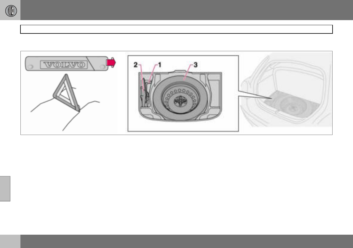
07 Wheels and tyres
150
Warning triangle and spare wheel
07
Warning triangle
Follow the regulations for the use of a warn-
ing triangle1. Position the warning triangle in
a suitable place with regard to traffic.
1. Undo the case containing the warning
triangle, it is secured with Velcro straps.
Take the warning triangle from the case.
2. Lower the warning triangle’s support
legs.
Ensure the warning triangle and its case are
properly secured in the cargo area after use.
Spare wheel and jack
The car’s original jack
The original jack2 must only be used for
changing wheels. The jack’s thread should
always be well greased. The spare wheel,
jack and wheel wrench are found under the
floor in the cargo area.
Taking out the spare wheel:
A bolt runs through to secure the spare
wheel.
– Fold up the cargo area floor.
– Unscrew the retaining bolt and lift out the
wheel.
Putting the spare wheel and jack into
the cargo area:
– Wheel wrench.
– Jack and handle, secured with a tension-
ing strap.
– The spare wheel is bolted down with the
rim side down using the through-bolt.
1Certain markets. 2Certain variants and markets.
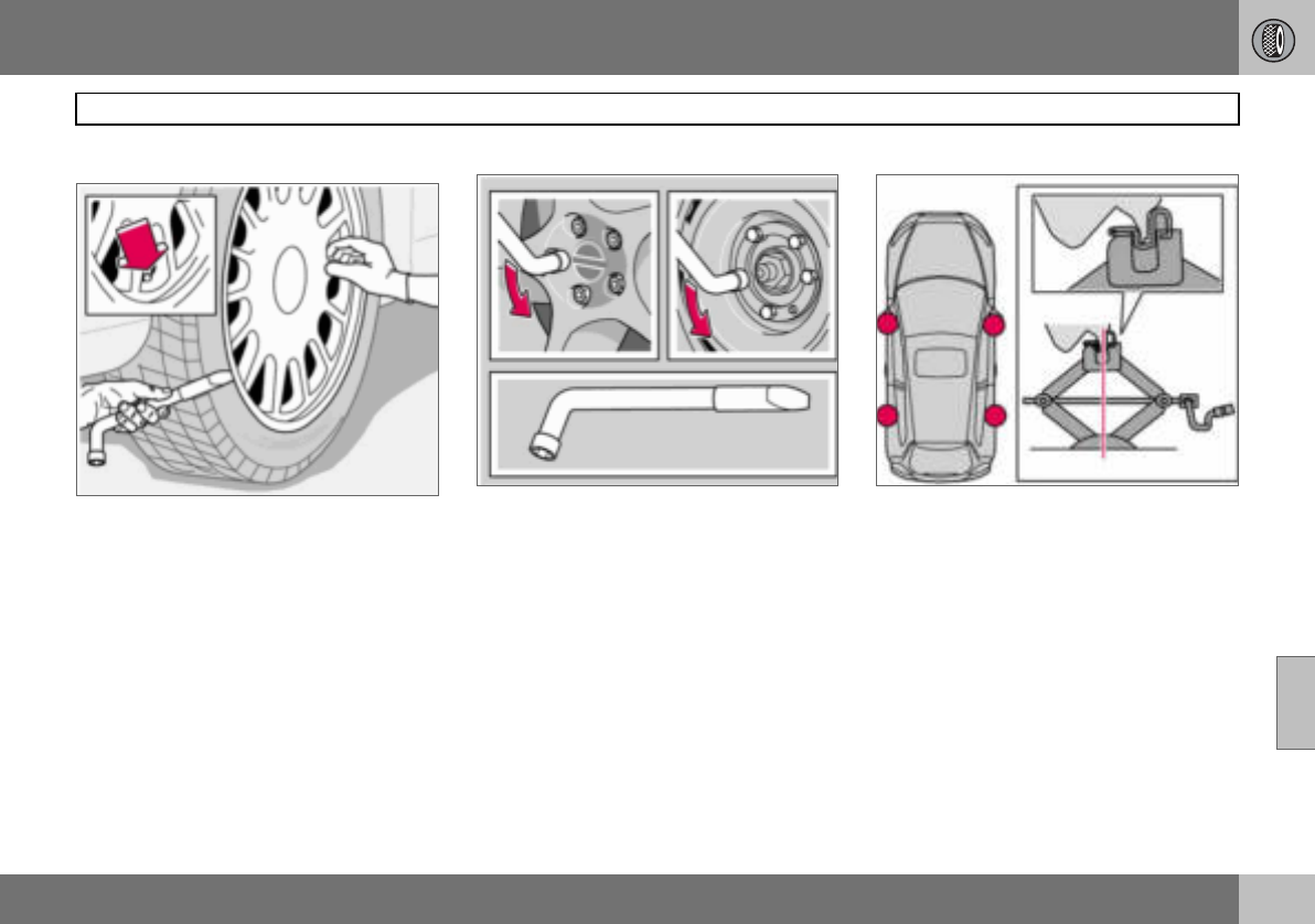
07 Wheels and tyres
151
Changing wheels
07
Removing wheels
Set up the warning triangle if a wheel must be
changed at a busy location. Make sure that
the car and jack are on a firm horizontal sur-
face.
– Take out the spare wheel, jack and wheel
wrench that are located under the carpet
in the cargo area.
– Apply the parking brake and engage first
gear, or position P if the car has an auto-
matic gearbox.
– Place chocks in front of and behind the
wheels which will remain on the ground.
Use heavy wooden blocks or large stones.
– Cars with steel rims have removable wheel
covers. Prise off the wheel cover with the
end of the wheel wrench, or pull it off by
hand.
– Loosen the wheel nuts ½–1 turn anticlock-
wise with the wheel wrench.
– There are two jacking points on each side
of the car. Crank the foot of the jack down
so it is pressed squarely on the ground.
Check that the jack sits in the anchorage
as illustrated and that the foot is posi-
tioned vertically under the anchorage.
– Lift the car so that the wheel is free.
Remove the wheel nuts and lift off the
wheel.
07 Wheels and tyres
152
Changing wheels
07
Fitting the wheel
– Clean the contact surfaces on the wheel
and hub.
– Put on the wheel. Tighten the wheel nuts.
– Lower the car so that the wheels cannot
rotate.
– Tighten the wheel nuts crosswise. It is
important that the wheel nuts are tight-
ened properly. Tighten to 90 Nm. Check
the torque with a torque wrench.
– Put on the wheel cover (steel rim).
WARNING
Never crawl under the car when it is raised
on the jack.
Passengers must leave the car when it is
raised on the jack.
Ensure that passengers wait with the car -
or preferably a crash barrier - between them
and the road.
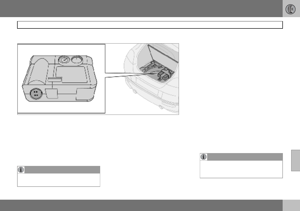
07 Wheels and tyres
153
Emergency puncture repair
07
General
Cars which do not have a spare wheel are in-
stead equipped with an emergency puncture
repair kit. The emergency puncture repair kit
can be used to both seal the puncture and to
check and adjust the tyre pressure. The
emergency puncture repair kit consists of an
electric air compressor and an integrated
canister with sealing liquid.
Emergency puncture repair kit
The emergency puncture repair kit1 is only in-
tended to work as a temporary repair so that
the car can be driven a further 200 km (max.)
or to the nearest tyre centre. The sealing fluid
has the capacity to effectively seal tyres
which have punctures in the tread.
The sealing fluid canister should be replaced
before its expiration date or after use of the
puncture repair kit.
The expiration date is located on the front of
the compressor, see the illustration on
page 158.
See page 158 for information on canister re-
placement.
NOTE
The jack is an option on cars equipped with
emergency puncture repair kit.
1Certain variants and markets.
NOTE
The emergency puncture repair kit is only
intended for sealing tyres with a puncture in
the tread.

07 Wheels and tyres
154
Emergency puncture repair
07
The emergency puncture repair kit has limit-
ed capacity to seal tyres which have punc-
tures in the wall. Do not seal tyres with the
emergency puncture repair kit if they have
larger slits, cracks, irregularities or similar
damage.
The emergency puncture repair kit with com-
pressor and tools are located under the floor
in the cargo area.
12 V sockets for the compressor are located
by the centre console and the rear seat.
Taking out the emergency puncture
repair kit
– Fold away the rear edge of the floor mat,
forward from the back.
– Lift up the emergency puncture repair kit.
WARNING
The sealing fluid may cause irritation if it
comes into direct contact with skin. In the
case of contact with skin, wash away the
fluid with soap and water.
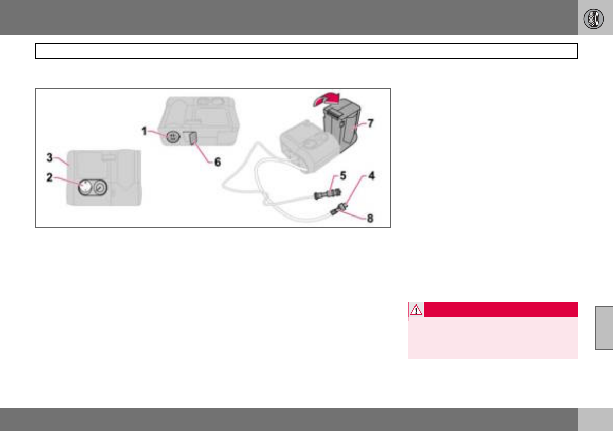
07 Wheels and tyres
155
Emergency puncture repair
07
Inflating tyres
Set up the warning triangle if a tyre must be
inflated in an area close to traffic.
– Ensure that the orange switch (2) is in
position 0 and take out the lead (5) and air
hose (4) from the side compartment (3).
– Screw the air hose’s valve connection to
the bottom of the thread on the tyre’s air
valve.
– Connect the lead (5) to one of the car’s
12 V sockets.
– Start the engine. The car must be in a well-
ventilated place.
– Start the compressor by flicking the
switch (2) to position I.
– Pump up the tyre to the pressure specified
on the tyre pressure label.
– Switch off the compressor, the switch (2)
should be in position 0. Detach the air
hose and unplug the lead. Refit the dust
cap.
– Put the lead (5) and air hose (4) into the
side compartment (3).
– Put the puncture repair kit back under the
floor in the cargo area.
– The compressor must not run for more
than ten minutes. Let it cool afterwards as
there is a risk of overheating.
– Objects with a volume up to 50 litres can
be inflated with the compressor.
WARNING
Inhaling car exhaust fumes can result in
danger to life. Never leave the engine run-
ning in sealed areas or areas that lack suffi-
cient ventilation.
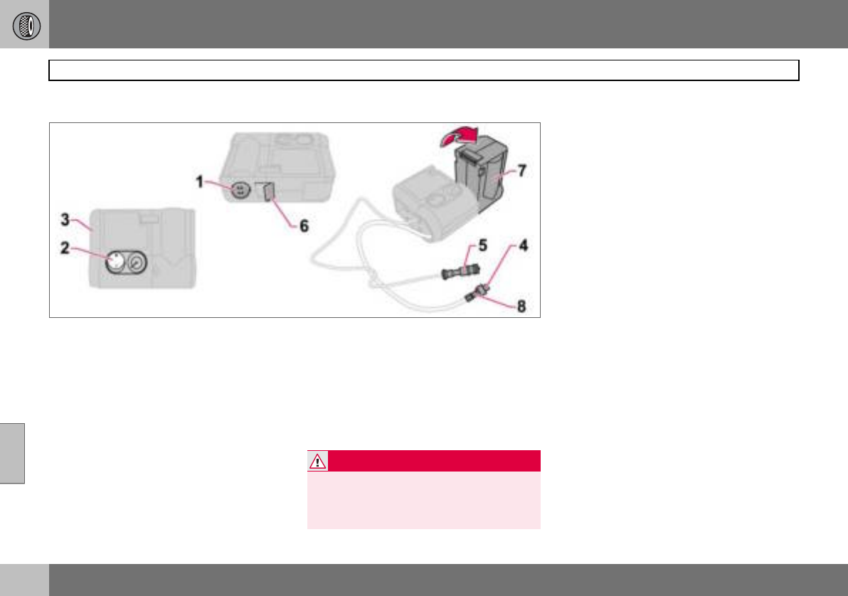
07 Wheels and tyres
156
Emergency puncture repair
07
Sealing punctured tyres
Set up the warning triangle if emergency tyre
repairs must be carried out in an area where
there is other traffic.
– Remove the decal (1) regarding the high-
est permitted speed from the emergency
puncture repair kit and stick it on the
steering wheel where it can be clearly
seen by the driver.
– Ensure that the orange switch (2) is in
position 0 and take out the lead (5) and air
hose (4) from the side compartment (3).
– Screw the air hose’s valve connection to
the bottom of the thread on the tyre’s air
valve.
– Connect the lead (5) to the car’s 12 V
socket.
– Release the safety catch (6) and turn the
orange-coloured part (7) 90 degrees to the
vertical position, until a click is heard.
– Start the engine. The car must be in a well-
ventilated place.
– Start the compressor by flicking the
switch (2) to position I. There will be a
temporary pressure increase of max. 4 bar
while the sealing fluid is pumped in. After
approx. one minute, the pressure will drop
and the gauge will indicate the correct tyre
pressure.
– Pump the tyre to a pressure of between
1.8 bar and 3.5 bar. If the pressure does
not reach 1.8 bar after ten minutes of
pumping, the compressor must be turned
off so it does not overheat.
WARNING
Inhaling car exhaust fumes can result in
danger to life. Never leave the engine run-
ning in sealed areas or areas that lack suffi-
cient ventilation.
07 Wheels and tyres
157
Emergency puncture repair
07
– Undo the air hose (4) from the tyre’s air
valve and refit the dust cap. Disconnect
the lead (5) from the electrical socket. Fold
the orange-coloured part (7) back into its
original position and secure the catch (6).
Keep the emergency repair kit in a safe
place in the car.
– Immediately drive about 3 km, at a maxi-
mum speed of 80 km/h, to allow the seal-
ing fluid to seal the tyre well.
Check the tyre pressure again:
– Connect the air hose (4) to the air valve on
the tyre. Connect the lead (5) to the 12 V
socket. Read the pressure on the com-
pressor. If the tyre pressure is below
1.3 bar, the tyre has not been sufficiently
well sealed. Under these circumstances
your journey should not be continued.
Contact a tyre centre.
– If the tyre pressure is higher than 1.3 bar,
the tyre should be pumped up to the
pressure stated on the tyre pressure label,
for location see page 148. Relieve pres-
sure with the reduction valve (8) if the tyre
pressure is too high.
– Switch off the compressor, the switch (2)
should be in position 0. Detach the air
hose and unplug the lead. Refit the dust
cap.
– Put the lead (5) and air hose (4) into the
side compartment (3).
– Put the puncture repair kit back under the
floor in the cargo area.
The compressor must not run for more than
ten minutes. Let it cool afterwards as there is
a risk of overheating.
WARNING
Never stand next to the tyre when the com-
pressor is running. Be particularly observ-
ant of the tyre walls. If cracks, irregularities
or other damage appears, turn off the com-
pressor immediately. Under these circum-
stances your journey should not continue.
Contact an authorised tyre centre.
WARNING
You should not drive faster than 80 km/h
after the emergency tyre repair kit has been
used. The temporarily sealed tyre must be
changed as soon as possible (maximum
driving distance: 200 km).
NOTE
Do not raise the orange-coloured part (7)
when only the compressor is to be used for
inflation.
NOTE
The canister with sealant and hose should
be replaced after use.
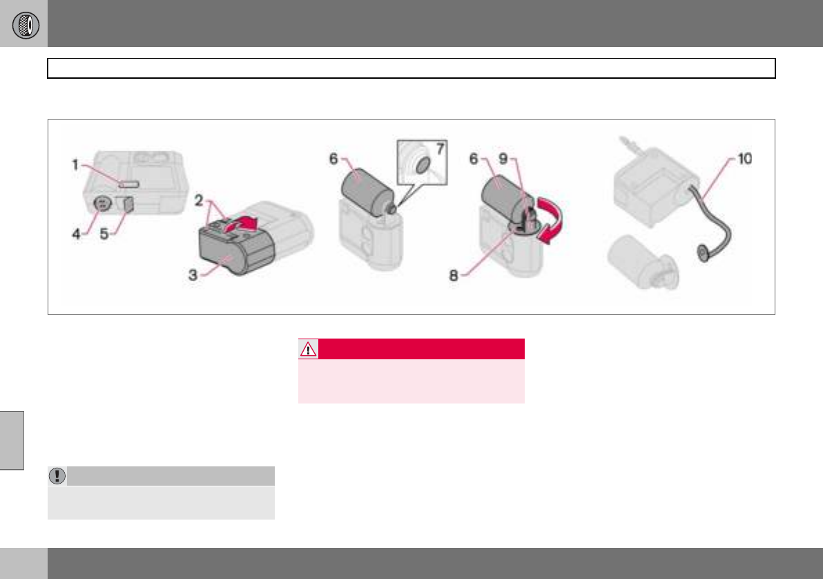
07 Wheels and tyres
158
Emergency puncture repair
07
Replacing the sealing fluid canister
The sealing fluid canister should be replaced
before its expiration date, see the date
label (1), or after puncture repair. After use,
the canister (6) with holder (8) and air
hose (10) should be replaced.
This replacement can be carried out by an
authorised Volvo workshop or by following
the instructions.
Replacing the canister before the
expiration date has been reached
– Undo the two screws (2) on the orange-
coloured case (3).
– Remove the speed label (4) and date
label (1), and open the safety catch (5).
Loosen the case (3) and take it off.
– Unscrew and remove the canister (6).
– Check that the seal (7) on the new canister
is not damaged. Screw in the canister.
– Refit the case (3). Check that the case is
correctly fitted. Screw it on with the
screws (2).
– Affix the speed label (4) and new date
label (1) to the tyre repair kit.
Treat the removed canister as hazardous
waste.
IMPORTANT
Read the safety instructions on the bottom
of the canister.
WARNING
Ensure the compressor is not connected to
the 12 V socket when the canister is re-
placed.

07 Wheels and tyres
159
Emergency puncture repair
07
Replacing the canister and hose after
use
– Undo the two screws (2) on the orange-
coloured case (3).
– Remove the speed label (4) and date
label (1), and open the safety catch (5).
Loosen the case (3) and take it off.
– Push down the button (8) while turning the
canister (6) and the holder (9) clockwise.
Remove them.
– Pull out the air hose (10).
– Wipe off remaining sealing fluid with a rag
or scrape it away if it is has already dried.
– Fit a new air hose (10). Check that it is
fitted correctly.
– Check that the seal (7) on the new canister
is not damaged. Screw the holder (9) onto
the canister (6) and turn it anticlockwise
until a click is heard.
– Refit the case (3). Check that the case is
correctly fitted. Screw it on with the
screws (2).
– Affix the speed label (4) and new date
label (1) to the tyre repair kit.
The empty canister and air hose can be treat-
ed as normal waste.

160
Cleaning ................................................................................................. 162
Touching up paintwork ........................................................................... 165
Rustproofing ..........................................................................................166
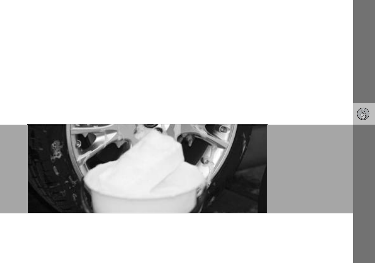
08
CAR CARE
08 Car care
162
Cleaning
08
Washing the car
Wash the car as soon as it becomes dirty.
Use car shampoo. Dirt and road salt can lead
to corrosion.
• Do not park the car in direct sunlight.
Washing a car with hot paintwork can
cause permanent paintwork damage.
Wash the car in a car wash with waste
water separator.
• Thoroughly rinse dirt off the underbody of
the car.
• Rinse the entire car to remove loose dirt.
When using a pressure washer: Make sure
that the nozzle of the pressure washer is
not closer than 30 cm to the bodywork. Do
not spray directly onto the locks.
• Wash using a sponge, car shampoo and
plenty of lukewarm water.
• If the dirt is difficult to dislodge, wash the
car using a cold degreasing agent.
• Dry the car using a clean, soft chamois or
a water scraper.
• Clean the wiper blades with a lukewarm
soap solution or car shampoo.
Removing bird droppings
Wash away bird droppings from the paint-
work as soon as possible. Bird droppings
contain chemicals that affect and discolour
paintwork very quickly. This discoloration
can only be removed by a specialist.
Automatic car washes
An automatic car wash is a simple and quick
way of washing the car, but it can never re-
place a proper handwashing. The brushes of
an automatic car wash cannot reach
everywhere.
Lightly depress the brake pedal now and
then when driving long distances in rain or
slush. This heats and dries the brake pads.
Do the same thing after starting in very damp
or cold weather.
Exterior plastic parts
A special cleaning agent, available from Vol-
vo dealers, is recommended for cleaning ex-
terior plastic parts. Never use strong stain re-
movers.
WARNING
Always have the engine cleaned by a work-
shop. There is a risk of fire if the engine is
hot.
NOTE
Outside lighting such as headlamps, fog
lamps and rear lamps may temporarily have
condensation on the inside of the lens. This
is a natural phenomenon, all outside lighting
is designed to withstand this. Condensation
is normally vented out of the lamp when it
has been switched on for a time.
WARNING
Always test the brakes after washing, so
that moisture and corrosion do not affect
the brake linings and impair the brakes.
IMPORTANT
Washing by hand is gentler to the paintwork
than an automatic car wash. Paintwork is
also more sensitive when it is new. For this
reason, handwashing is recommended dur-
ing the first few months with a new car.
08 Car care
163
Cleaning
08
Polishing and waxing
Polish and wax the car if the paintwork is dull
or to give the paintwork extra protection.
The car does not need to be polished until it
is at least one year old. However, the car can
be waxed before this time. Do not polish or
wax the car in direct sunlight.
Wash and dry the car thoroughly before you
begin polishing or waxing. Clean off asphalt
and tar stains using Volvo tar remover or
white spirit. More stubborn marks can be re-
moved using fine rubbing paste designed for
car paintwork.
Polish first with a polish and then wax with
liquid or solid wax. Follow the instructions on
the packaging carefully. Many preparations
contain both polish and wax.
Cleaning door mirrors and front side
windows with water-repellent surface
(option)
Never use products such as car wax, de-
greaser or similar on mirror/glass surfaces as
this could ruin their water-repellent proper-
ties.
Take care when cleaning so as not to dam-
age the glass surface.
To avoid damaging glass surfaces when re-
moving ice – only use plastic ice scrapers.
There is natural wear of the water-repellent
coating.
Treatment with a special finishing agent
available from Volvo dealers is recommend-
ed in order to maintain the water-repellent
properties. This should be used first after
three years and then each year.
Cleaning the interior
Treating stains on fabric upholstery
A special cleaning agent, available from Vol-
vo dealers, is recommended for cleaning the
fabric upholstery. Other chemicals can impair
the fire retardant qualities of the upholstery.
Treating stains on leather upholstery
Volvo’s leather upholstery is equipped with
surface protection against dirt. Cleaning re-
protects the leather but grease and dirt dis-
solves the surface protection. There is a
comprehensive programme for the care and
maintenance of leather upholstery. Volvo of-
fers a leather product for cleaning and treat-
ing the upholstery by which means the leath-
er regains its protective layer.
IMPORTANT
Paint treatment such as preserving, sealing,
protection, lustre sealing or similar could
damage the paintwork. Paintwork damage
caused by such treatment is not covered by
Volvo warranty.
IMPORTANT
Sharp objects and Velcro may damage the
fabric upholstery.
IMPORTANT
Never use strong solvents. Such products
may damage fabric, vinyl and leather uphol-
stery.
08 Car care
164
Cleaning
08
To achieve best results Volvo recommends
cleaning and application of the protective
cream two to four times per year.
Ask your Volvo dealer about Volvo’s Leather
Care product
Washing instructions for leather
upholstery
– Pour the leather cleaner on the dampened
sponge and squeeze out a strong foam.
– Work the dirt away with gentle circular
movements.
– Dab the sponge accurately on the stains.
Allow the sponge to absorb the stain. Do
not rub.
– Wipe off with soft paper or a cloth and
allow the leather to dry completely.
Protective treatment of leather uphol-
stery
– Pour a small amount of the protective
cream on the felted cloth and massage in
a thin layer of cream with gentle circular
movements on the leather.
– Now allow the leather to dry for
20 minutes before use.
– The leather has now been given improved
protection against stains and a UV filter.
Treating stains on interior plastic parts
and surfaces
A special cleaning agent, available from Vol-
vo dealers, is recommended for cleaning in-
terior plastic parts and surfaces. Do not
scrape or rub stains. Never use strong stain
removers.
Cleaning seatbelts
Use water and a synthetic detergent. A spe-
cial textile cleaning agent is available from
your Volvo dealer. Make sure the seatbelt is
dry before allowing it to retract.
IMPORTANT
Note that materials with colour that runs
when dry (new jeans, suede garments etc.)
may discolour the upholstery material.
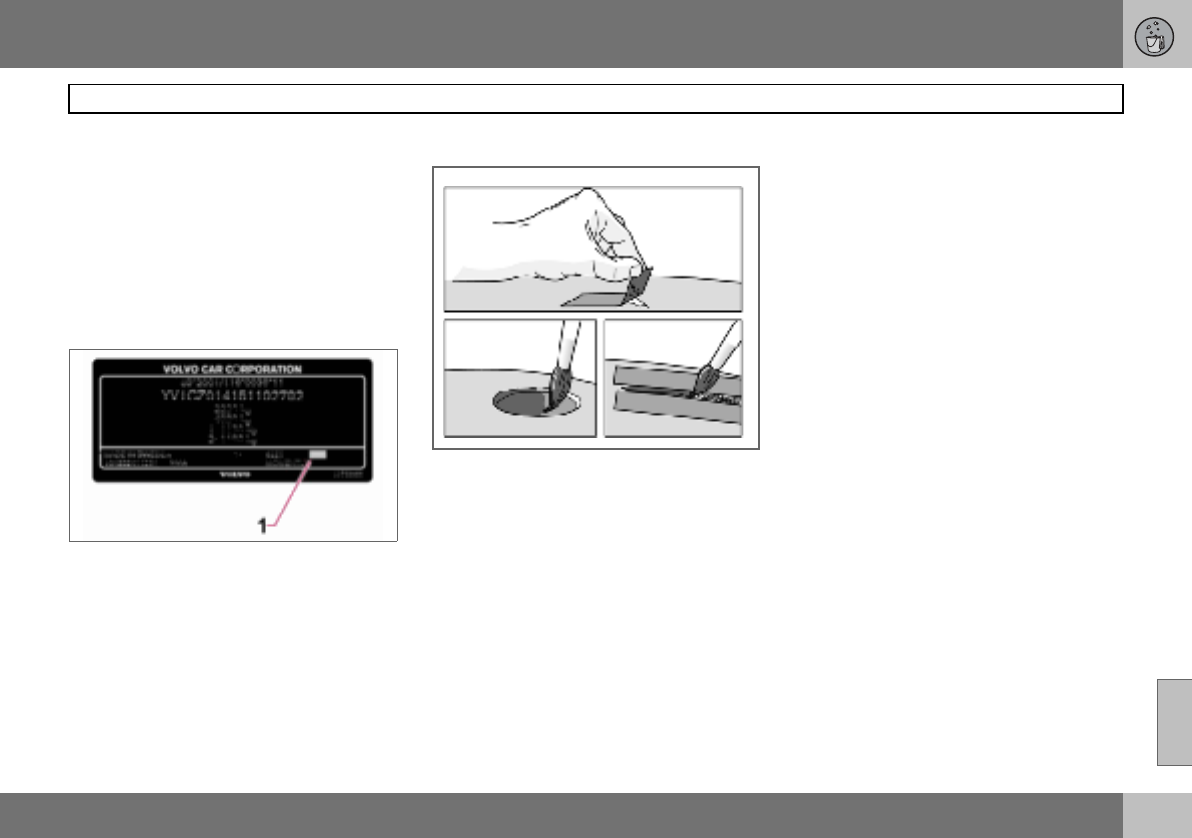
08 Car care
165
Touching up paintwork
08
Paintwork
Paint is an important part of the car’s rust-
proofing and should therefore be checked
regularly. To avoid the onset of rust, dam-
aged paintwork should be rectified immedi-
ately. The most common types of paintwork
damage are stone chips, scratches, and
marks on the edges of wings and doors.
Colour code
Data plate
It is important that the correct colour is used.
The colour code number (1) is shown on the
data plate, see page 220.
Stone chips and scratches
Before touching up paintwork, the car must
be clean and dry and at a temperature
above 15 C.
Materials
• Primer in a can
• Paint in a can or touch-up pen
•Brush
•Masking tape
Minor stone chips and scratches
If the stone chip has not penetrated to the
bare metal and there is an undamaged colour
coat, you can paint straight after cleaning the
damaged area.
If the stone chip has penetrated to the
bare metal
– Apply a piece of masking tape over the
damaged surface. Then remove the tape
to remove any loose paint.
– Stir the primer well and apply using a fine
brush or a matchstick. Apply paint using a
brush once the primer is dry.
– For scratches, proceed as above, but
mask around the damaged area to protect
the undamaged paintwork.
– After a few days, polish the touched-up
areas. Use a soft rag and a small amount
of lapping paste.

08 Car care
166
Rustproofing
08
Inspection and maintenance
Your car has already received a thorough
and complete rustproofing at the factory.
Parts of the body are made of galvanised
sheet metal. The underbody is protected by a
wear-resistant anti-corrosion compound. A
thin, penetrating rustproofing fluid was
sprayed into the members, cavities and
closed sections.
Maintaining the car’s rustproofing.
• Keep the car clean. Hose down the under-
body. If using a pressure washer, keep the
nozzle at least 30 cm from the painted
surfaces.
• Regularly check and touch-up the rust-
proofing treatment as necessary.
The car’s rustproofing does not normally re-
quire treatment for approximately 12 years.
After this period, it should be treated at
three-year intervals. If the car needs further
treatment, please contact an authorised Vol-
vo workshop.

08 Car care
167
08

168
Volvo service .......................................................................................... 170
Self-maintenance ................................................................................... 171
Bonnet and engine compartment .......................................................... 172
Diesel ..................................................................................................... 173
Oils and fluids ........................................................................................ 174
Wiper blades .......................................................................................... 178
Battery .................................................................................................... 179
Replacing bulbs ..................................................................................... 181
Fuses ...................................................................................................... 187
09
MAINTENANCE AND SERVICE
09 Maintenance and service
170
Volvo service
09
Volvo service programme
Before the car left the factory, it was thor-
oughly test driven. It was checked again in
accordance with Volvo Car Corporation reg-
ulations before it was handed over to you.
To keep your Volvo as safe and reliable as
possible, follow the Volvo service pro-
gramme specified in the Service and Warran-
ty Booklet. Have an authorised Volvo work-
shop carry out service and maintenance
work. Volvo workshops have the personnel,
special tools and service literature to guaran-
tee the highest quality of service.
Special service measures
Certain service measures which affect the
car’s electrical system can only be per-
formed using electronic equipment specially
developed for your car. For this reason, al-
ways contact an authorised Volvo workshop
before beginning or performing service work
that affects the electrical system.
Installing accessories
The incorrect connection and installation of
accessories can negatively affect the car’s
electrical system. Certain accessories only
function when the appropriate software has
been programmed into the car’s electrical
system. Always contact an authorised Volvo
workshop before installing accessories
which are connected to or affect the electri-
cal system.
Recording vehicle data
One or more of the computers in your Volvo
are capable of recording detailed informa-
tion. This information is intended for use in
research to enhance safety and for diagnos-
ing faults in some of the in-car systems. The
data may include details regarding seatbelt
use by the driver and passengers, the func-
tions of various vehicle systems and mod-
ules, and status information about the en-
gine, throttle, steering, brakes and other sys-
tems. This data can also include details of
the way the car is driven. This type of infor-
mation can include, without being limited to,
specific details such as vehicle speed, the
use of the brake and accelerator pedals and
steering wheel position. This latter type of
data can be stored for a limited period while
the car is being driven and subsequently dur-
ing a collision or a near-collision. Volvo Car
Corporation will not disclose the stored infor-
mation without consent. However, Volvo Car
Corporation may be forced to disclose the in-
formation due to national legislation. Volvo
Car Corporation and authorised Volvo work-
shops may also read and use the informa-
tion.
Adverse driving conditions
Check the oil level more frequently for long
journeys:
• Towing a caravan or trailer
• In mountainous regions
•At high speeds
• In temperatures colder than –30 C or
hotter than +40 C.
Also check the oil level more often if the car
is often driven short distances (less than
10 km) when temperatures are low
(below +5 C).
This can produce abnormally high oil temper-
ature or oil consumption.
IMPORTANT
For the Volvo warranty to apply, check and
follow the instructions in the Service and
Warranty Booklet.
09 Maintenance and service
171
Self-maintenance 09
Before starting work on the car
Battery
Check that the battery cables are correctly
connected and tightened.
Never disconnect the battery when the en-
gine is running (e.g. if replacing the battery).
Never use a quick charger to charge the bat-
tery. The battery cables must be disconnect-
ed when charging the battery.
The battery contains acid that is both corro-
sive and toxic. It is therefore important to
handle the battery in an environmentally-suit-
able way. Let your Volvo dealer assist you.
Check regularly
Check the following at regular intervals, for
example, when refuelling:
• Coolant – The level must be between the
MIN and MAX marks on the expansion
tank.
• Engine oil – The level must be between the
MIN and MAX marks.
• Power steering fluid – The level must be
between the MIN and MAX marks.
• Washer fluid – The reservoir should be well
filled. Use washer antifreeze at tempera-
tures around freezing.
• Brake and clutch fluid – The level must be
between the MIN and MAX marks.
WARNING
High output from the ignition system. The
voltage in the ignition system is highly dan-
gerous. The ignition must therefore always
be switched off for work in the engine com-
partment.
Do not touch the spark plugs or ignition
coils when the ignition is on or the engine is
hot.
WARNING
Bear in mind that the radiator fan may start
automatically some time after the engine
has been switched off.
Always have the engine cleaned by a work-
shop. There is a risk of fire if the engine is
hot.
09 Maintenance and service
172
Bonnet and engine compartment
09
Opening the bonnet
To open the bonnet:
– Pull the handle on the far left under the
dashboard. You will hear when the catch
releases.
– Insert your hand under the centre of the
front edge of the bonnet and press the
safety catch to the right.
– Open the bonnet.
Engine compartment
1. Washer fluid reservoir (4-cyl.) Illustration
is slightly simplified
2. Coolant expansion tank
3. Reservoir for the power steering fluid
(concealed behind the headlamp)
4. Engine oil dipstick1
5. Radiator
6. Radiator fan
7. Washer fluid reservoir (5-cyl.)
8. Brake and clutch fluid reservoir (right-
hand drive)
9. Filler opening for engine oil1
10.Brake and clutch fluid reservoir (left-
hand drive)
11.Battery
12.Relay and fuse box
13.Air filter1
WARNING
Check that the bonnet locks properly when
closed. 1Dependent on engine variant.
09 Maintenance and service
173
Diesel 09
Fuel system
Diesel must fulfil the EN 590 or JIS K2204
standards. Diesel engines are sensitive to
contaminants, such as high volumes of sul-
phur particles for example. Only use diesel
fuel from a well-known producers. Never use
diesel of dubious quality.
At low temperatures (–40 C to –6 C), a par-
affin precipitate may form in the diesel fuel,
which can lead to ignition problems. The ma-
jor oil companies produce a special winter-
grade diesel for temperatures around freez-
ing. This fuel is less viscous at low tempera-
tures and reduces the risk of paraffin precipi-
tate.
The risk of condensation in the fuel tank is re-
duced if the tank is kept well filled. When re-
fuelling, check that the area around the fuel
filler pipe is clean. Avoid spilling fuel onto the
paintwork. Wash off any spillage with deter-
gent and water.
Empty tank
No special procedures are required if the
tank runs dry. The fuel system is bled auto-
matically if the ignition switch is kept in
position II for approx. 60 seconds before the
start attempt.
Draining condensation from the fuel
filter
The fuel filter separates condensation from
the fuel. Condensation can disrupt engine
operation.
The fuel filter must be drained at the intervals
specified in the Service and Warranty Book-
let or if you suspect that the car has been
filled with contaminated fuel.
IMPORTANT
Diesel type fuels which must not be used:
special additives, Marine Diesel Fuel, fuel
oil, RME (Rape Methyl Ester) and vegetable
oil. These fuels do not fulfil the requirements
in accordance with Volvo recommendations
and generate increased wear and engine
damage that is not covered by the Volvo
warranty.
IMPORTANT
For model year 2006 or later the sulphur
content must be a maximum of 50 ppm.
IMPORTANT
Certain special additives remove the water
separation in the fuel filter.
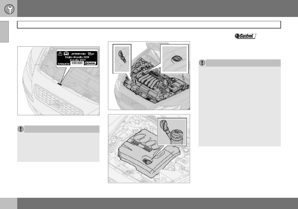
09 Maintenance and service
174
Oils and fluids
09
Engine compartment decal for oil
grade
Using oil of a higher than specified grade is
permitted. If the car is driven in adverse con-
ditions, Volvo recommends using an oil of a
higher grade than that specified on the decal.
See page 226.
Checking the engine oil and oil filter
Dipstick, petrol engines
Dipstick, diesel engines
Volvo recommends oil products.
Change the oil and oil filter in accordance
with the intervals specified in the Service and
Warranty Booklet.
IMPORTANT
Always use oil of the prescribed grade, see
the engine compartment decal. Check the
oil level frequently and change the oil regu-
larly. The engine will be damaged if lower
grade oil is used or if the car is driven with
the oil level too low.
IMPORTANT
In order to fulfil the requirements for the en-
gine’s service intervals all engines are filled
with a specially adapted synthetic engine oil
at the factory. The choice of oil has been
made very carefully with regard to service
life, starting characteristics, fuel consump-
tion and environmental impact. An ap-
proved engine oil must be used in order that
the recommended service intervals can be
applied. Only use a prescribed grade of oil
(see the engine compartment decal) for
both filling and oil change, otherwise you
will risk affecting service life, starting char-
acteristics, fuel consumption and environ-
mental impact. Volvo Car Corporation
disclaims all warranty liability if engine oil of
the prescribed grade and viscosity is not
used.
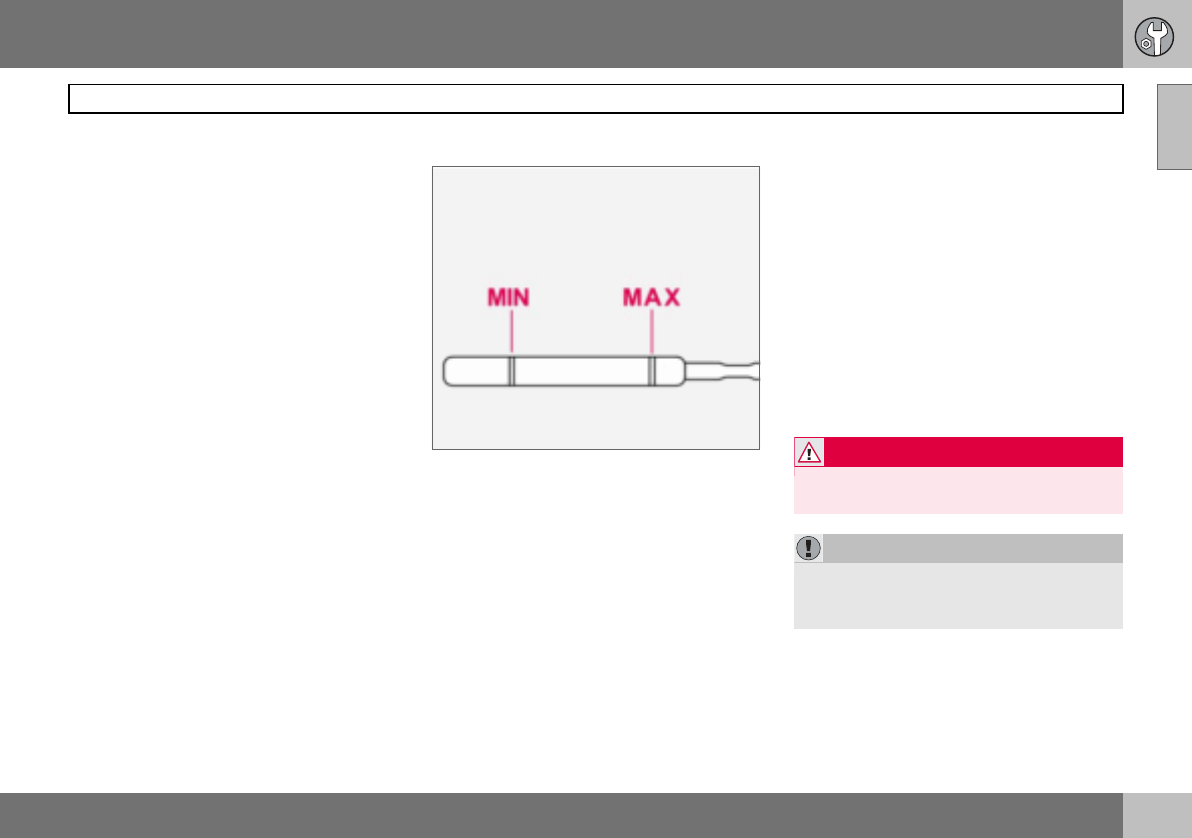
09 Maintenance and service
175
Oils and fluids 09
Volvo uses different systems for warning of
low oil level or low oil pressure. Certain vari-
ants have an oil pressure sensor, and then
the lamp for oil pressure is used. Other vari-
ants have an oil level sensor, and then the
driver is informed via the warning symbol in
the centre of the instrument unit as well as by
display texts. Certain models have both vari-
ants. Contact an authorised Volvo dealer for
more information.
Checking the oil level in a new car is espe-
cially important before the first scheduled oil
change. The Service and Warranty Booklet
specifies the odometer readings for oil
changes.
Volvo recommends checking the oil level
every 2 500 km. The most accurate measure-
ments are made on a cold engine before
starting. The measurement will be inaccurate
if taken immediately after the engine is
switched off. The dipstick will indicate that
the level is too low because the oil has not
had time to flow down into the oil sump.
Checking the oil
The oil level must be within the area marked on
the dipstick.
Checking the oil in a cold engine:
– Wipe the dipstick clean before checking
the level.
– Check the oil level using the dipstick. The
level must be between the MIN and MAX
marks.
– If the level is close to the MIN mark, start
by topping up with 0.5 litres. Top up until
the oil level is nearer the MAX than the
MIN mark on the dipstick. See page 226–
227 for capacities.
Checking the oil in a warm engine:
– Park the car on a level surface, switch off
the engine and wait 10–15 minutes to
allow the oil time to run back to the sump.
– Wipe the dipstick clean before checking
the level.
– Check the oil level using the dipstick. The
level must be between the MIN and MAX
marks.
If the level is close to the MIN mark, start by
topping up with 0.5 litres. Top up until the oil
level is nearer the MAX than the MIN mark on
the dipstick. See page 226–227 for
capacities.
WARNING
Do not spill oil onto the hot exhaust mani-
fold due to the risk of fire.
IMPORTANT
Never fill above the MAX mark. Oil con-
sumption may increase if too much oil is
poured into the engine.
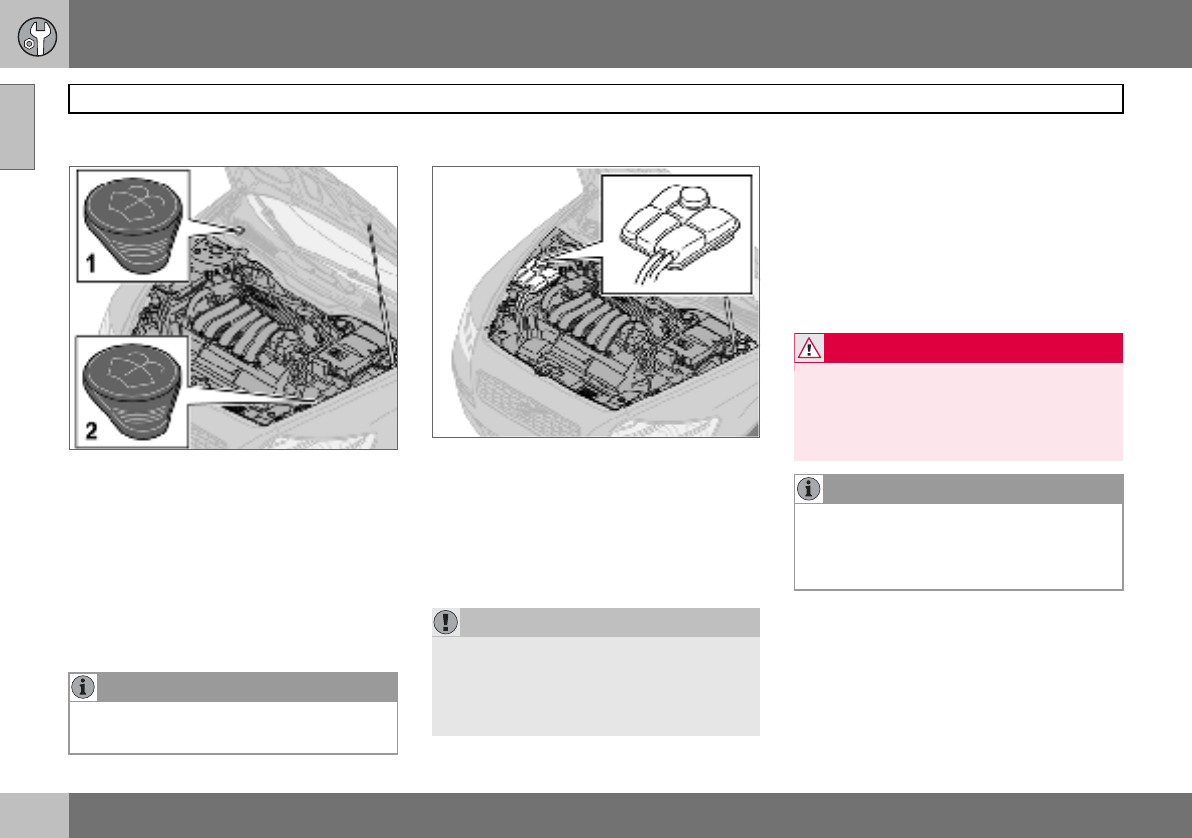
09 Maintenance and service
176
Oils and fluids
09
Washer fluid, topping up
Location of washer fluid reservoir.
The windscreen and headlamp washers
share a common reservoir.
– Filler cap on 4-cylinder engines and diesel.
– Filler cap on 5-cylinder engines.
Add washer antifreeze during the winter so
that the fluid does not freeze in the pump,
reservoir and hoses. For capacities, see
page 231.
Checking and topping up the coolant
When topping up the coolant, follow the in-
structions on the packaging. It is important
that the mixture of coolant concentrate and
water is correct for the prevailing weather
conditions. Never top up with water only. The
risk of freezing increases with both too little
and too much coolant concentrate.
For capacities, see page 230.
Check the coolant regularly
The level must lie between the MIN and MAX
marks on the expansion tank. If the system is
not filled sufficiently, high local temperatures
could occur, causing a risk of damage
(cracks) to the cylinder head. Top up the
coolant when the level falls to the MIN mark.
NOTE
Mix the washer antifreeze and water before
filling the reservoir.
IMPORTANT
Always use coolant with anti-corrosion
agent as recommended by Volvo. New cars
are filled with coolant that can withstand
temperatures down to approximately
–35 C.
WARNING
Coolant can be very hot. If the coolant re-
quires topping up when the engine is at op-
erating temperature, unscrew the
expansion tank cap slowly to gently release
the overpressure.
NOTE
The engine must only be run with a well-
filled cooling system. High temperatures
can occur, causing a risk of damage
(cracks) to the cylinder head.
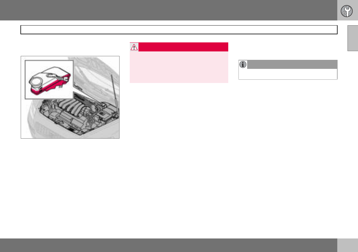
09 Maintenance and service
177
Oils and fluids 09
Checking and topping up the brake
and clutch fluid
The brake and clutch fluid have a common
reservoir1. The fluid level must be between
the MIN and MAX marks. Check the level
regularly. Change the brake fluid every other
year or at every other regular service.
See the capacities and recommended fluid
grade on page 231.
The fluid should be changed annually on cars
driven in conditions requiring hard, frequent
braking, such as driving in mountains or trop-
ical climates with high humidity.
Checking and topping up the power
steering fluid
The fluid does not require changing. For ca-
pacities and recommended fluid grade, see
page 231.
If a fault should arise in the power steering
system or if the car is without power and
must be towed, it can still be steered. How-
ever, the steering will be much heavier than
normal and it will require more effort to turn
the steering wheel.
1Location dependent on whether car is left or
right-hand drive.
WARNING
If the brake fluid is under the MIN level in
the brake fluid reservoir, do not drive further
before topping up the brake fluid.
The reason for the loss of brake fluid must
be investigated.
NOTE
Check the level frequently.
09 Maintenance and service
178
Wiper blades
09
Replacing the wiper blades
– Turn up the wiper arm.
– Press the button located on the wiper
blade mounting and pull straight out (1),
parallel with the wiper arm.
– Slide in (2) the new wiper blade until a
"click" is heard.
– Check (3) that the blade is firmly installed.
– Fold down the wiper arm.
Replacing the wiper blades, rear
window
– Fold out the wiper arm.
– Detach the wiper blade by moving it
straight out from the wiper arm.
– Press the new wiper blade into position.
Check that it is firmly installed.
– Lower the wiper arm.
NOTE
The wiper blades are different lengths. The
blade on the driver’s side is longer than on
the other side.
09 Maintenance and service
179
Battery 09
Battery care
There may be two different types of battery.
They are fully interchangeable with each other.
The service life and function of the battery is
influenced by factors such as the number of
starts, discharging, driving style, driving con-
ditions and climatic conditions.
For the battery to function satisfactorily:
• Regularly check that the electrolyte level is
correct (A) and never fill above the level
mark.
• Check all of the cells. Use a screwdriver to
remove the cell caps (or the cover).
• If necessary, top up with distilled water to
the battery’s maximum mark.
• Fit the cell caps (or the cover) firmly.
IMPORTANT
Always use distilled or deionised water (bat-
tery water).
NOTE
An expended battery must be recycled in an
environmentally responsible manner as it
contains lead.
WARNING
Batteries can generate oxyhydrogen gas,
which is highly explosive. One spark, which
can be generated if you connect the jump
leads incorrectly, is sufficient to make the
battery explode.The battery contains sul-
phuric acid, which can cause serious burns.
If the acid comes into contact with eyes,
skin or clothing, flush with large quantities
of water. If acid splashes into the eyes, seek
medical attention immediately.
NOTE
The life of the battery is shortened if it be-
comes discharged repeatedly
09 Maintenance and service
180
Battery
09
Symbols on the battery
Use protective goggles.
Further information in the
owner’s manual.
Store the battery out of the
reach of children.
The battery contains corro-
sive acid.
Avoid sparks and naked
flames.
Risk of explosion. Replacing the battery
Removing the battery
– Switch off the ignition and remove the key.
– Wait at least 5 minutes before touching
any electrical terminals. This allows time
for the information in the car’s electrical
system to be stored in the different control
modules.
– Remove the cover.
– Disconnect the negative battery lead.
– Disconnect the positive battery lead.
– Undo the front wall of the battery box
using a screwdriver.
– Release the clamp securing the battery.
– Remove the battery.
Fitting the battery
– Fit the battery into position.
– Fit the clamp securing the battery.
– Reinstall the front wall of the battery box.
– Connect the positive lead.
– Connect the negative lead.
– Refit the cover over the battery.
09 Maintenance and service
181
Replacing bulbs 09
General
All bulb specifications are given on page 236.
The following list contains bulbs and point-
source lamps that are specialised or unsuita-
ble for replacement except at a workshop:
• General interior lighting in the roof
• Reading lamps and glovebox lighting
• Indicator, door mirror and approach light-
ing
• High-level brake light
• Bi-Xenon headlamp
Replacing front bulbs
All front bulbs (except for fog lamps) are re-
placed by first removing the lamp housing
from the engine compartment.
Removing the lamp housing:
– Remove the ignition key and turn the light
switch to position 0.
– Withdraw the lamp housing’s locking
pin (1).
– Pull the lamp housing to the side and then
forward (2) .
– Unplug the connector by pressing down
the clip with a thumb (3) while moving out
the connector (4) with the other hand.
– Lift out the lamp housing and place it on a
soft surface to avoid scratching the lens.
Fitting the lamp housing:
– Plug in the connector and refit the lamp
housing and locking pin. Check that the
pin is correctly inserted.
– Check the lighting.
The lamp housing must be plugged in and
secured in place before the lighting is turned
on or the ignition key inserted into the ignition
switch.
WARNING
On cars with Bi-Xenon headlamps the re-
placement must be carried out by an au-
thorised Volvo workshop. The headlamps
must be handled with extreme care due to
the high-voltage unit in the Xenon lamp.
IMPORTANT
Never touch the glass part of the bulbs with
your fingers. Grease and oil from your fin-
gers are vaporised by the heat, coating the
reflector and then causing damage.
IMPORTANT
Do not pull the electrical cable, only the
connector.
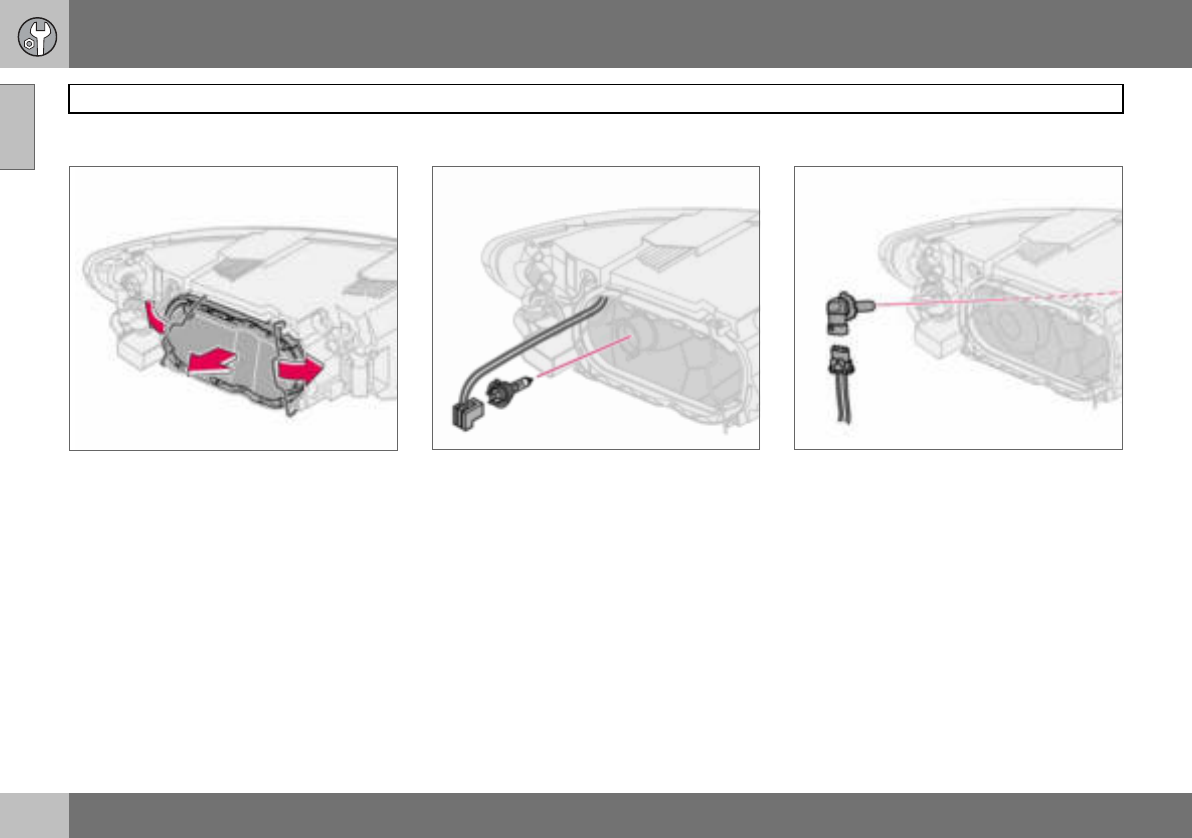
09 Maintenance and service
182
Replacing bulbs
09
Dipped beam
Removing the cover and bulb:
– Remove the entire lamp housing.
– Bend aside the catches and remove the
cover.
– Unplug the connector from the bulb.
– Release the spring clip securing the bulb.
First, press it to the left to release it, then
out and down.
– Pull out the bulb.
– Refit the lamp housing.
Fitting a new bulb
– Fit the new bulb. It can only fit in one
position.
– Press the spring clip up and then slightly
to the right so that it clicks into place.
– Press the connector back on.
– Refit the plastic cover.
– Refit the lamp housing.
Main beam
– Remove the entire lamp housing.
– Left-hand headlamp:
Turn the bulb holder anticlockwise.
Right-hand headlamp:
Turn the bulb holder clockwise.
– Withdraw the bulb holder and replace the
bulb.
– Refit the bulb holder. It can only be refitted
in one position.
– Refit the lamp housing.
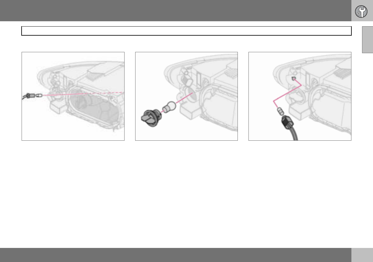
09 Maintenance and service
183
Replacing bulbs 09
Position/parking lamps
– Withdraw the bulb holder using pliers. Do
not pull out the bulb holder by pulling the
electrical cable.
– Replace the bulb.
– Press the bulb holder back on. It can only
be refitted in one position.
Direction indicators
– Twist the bulb holder anticlockwise and
remove it.
– To remove the bulb from the bulb holder,
press the bulb in and turn it anticlockwise.
– Fit a new bulb and refit the bulb holder into
the lamp housing.
Side marker lamps
– Twist the bulb holder anticlockwise and
withdraw it. Replace the bulb.
– Refit the bulb holder. It can only fit in one
position.
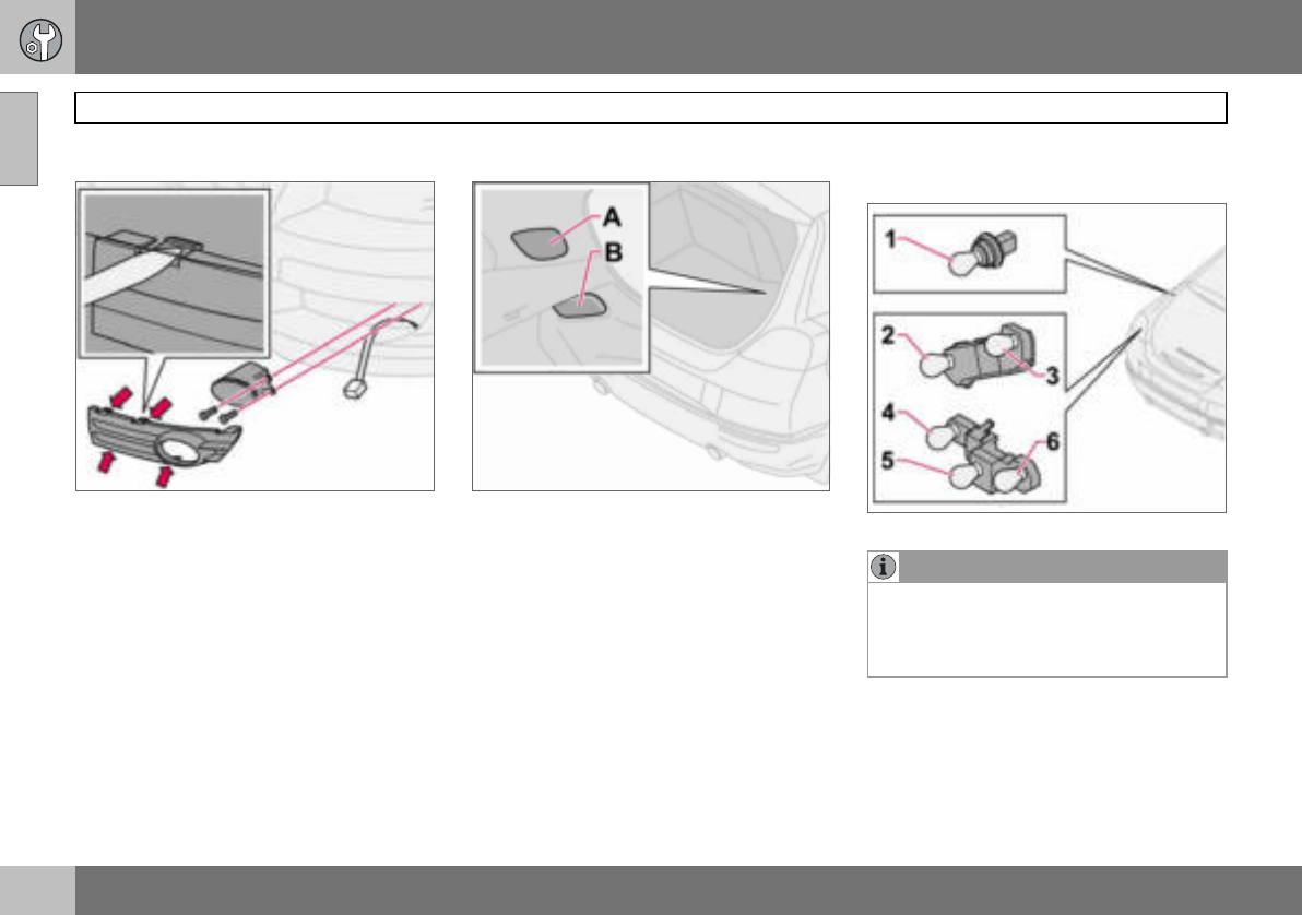
09 Maintenance and service
184
Replacing bulbs
09
Fog lamps
– Switch off all lights and turn the ignition
key to position 0.
– Remove the panel from around the lamp
housing.
– Remove the two Torx screws securing the
lamp housing and take out the lamp hous-
ing.
– Unplug the connector from the bulb.
– Turn the bulb anticlockwise and pull it out.
– Fit the new bulb and turn it clockwise.
– Plug in the connector to the bulb.
– Secure the lamp housing with the screws
and press the panel back into place.
Removing the bulb holder
– All bulbs in the rear lamp cluster can be
replaced from inside the cargo area.
Switch off all lights and turn the ignition
key to position 0.
– Remove the covers (A or B) in the left/
right-hand panel to access the bulbs. The
bulbs are located in separate bulb holders.
– Unplug the connector from the bulb hold-
er.
– Press the catches together and pull out
the bulb holder.
– Replace the bulb and plug in the connec-
tor. Press the bulb holder into place and
refit the cover (A or B).
Location of the bulbs in the rear lamp
cluster
Bulb holder
1. Brake light
2. Position/parking and fog lamps
3. Position/parking lamps
4. Indicator
5. Reversing lamp
6. Position/parking lamps
NOTE
If the error message BULB FAILURE/
CHECK STOP LAMP remains after a faulty
bulb has been replaced then consult an au-
thorised Volvo workshop.
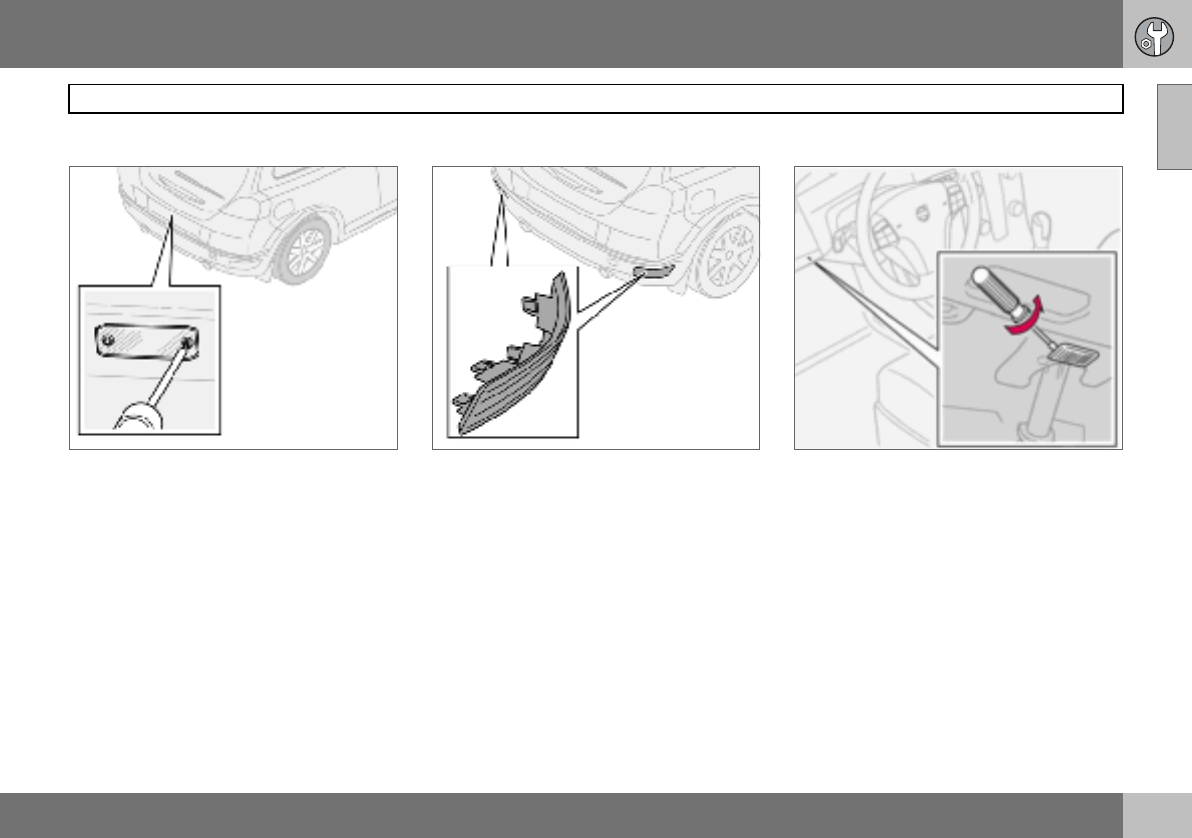
09 Maintenance and service
185
Replacing bulbs 09
Number plate lighting
– Switch off all lights and turn the ignition
key to position 0.
– Remove the screws with a screwdriver.
– Detach the lens carefully.
– Replace the bulb.
– Refit and screw in the lens.
Reflector
The reflector is secured with clips and is
pressed in. It can only fit in one position.
Courtesy lighting
– There is courtesy lighting under the dash-
board on the driver and passenger sides.
– Insert a screwdriver and gently turn so that
the lens detaches.
– Remove the blown bulb.
– Fit a new bulb.
– Refit the lens.
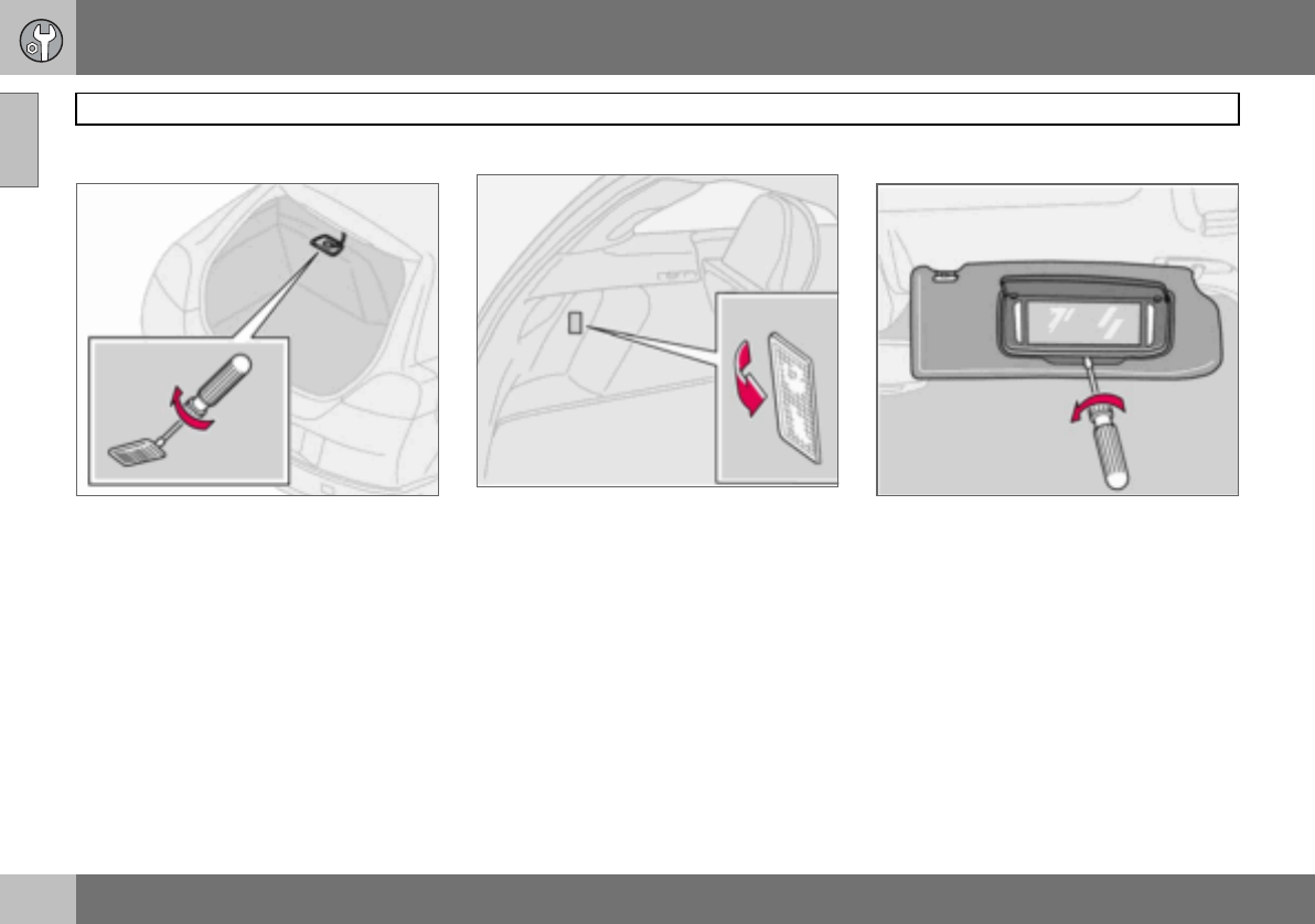
09 Maintenance and service
186
Replacing bulbs
09
Cargo area
Insert a screwdriver and gently turn so that
the lamp housing comes loose.
Interior lighting in cargo area
Cargo area lighting also includes a further
lamp on the left-hand side of the cargo area.
– Insert a screwdriver and gently turn so that
the lens detaches.
– Unplug the connector from the bulb hold-
er.
Vanity mirror lighting
Removing the mirror glass:
– Insert a screwdriver underneath the lower
edge, in the centre. Carefully prise up the
lug on the edge.
– Insert the screwdriver underneath the
edge on the left and right-hand sides (by
the black rubber sections), and prise care-
fully so that the glass comes loose in the
lower edge.
– Carefully detach and lift aside the entire
mirror glass and cover.
Fitting the mirror glass:
– First, press the three lugs at top edge of
mirror glass back into position, then press
in the three lower ones.

09 Maintenance and service
187
Fuses 09
General
All electrical functions and components are
fused to protect the car’s electrical system
from damage by short circuiting and over-
loading.
The fuses are in two different locations in the
car:
• Relay/fuse box in the engine compartment
• Relay/fuse box in the passenger compart-
ment.
Replacement
If an electrical component or function does
not work, it may be because the compo-
nent’s fuse was temporarily overloaded and
blew.
– Look in the fuse diagram to locate the
fuse.
– Pull out the fuse and check from the side
to see whether the curved wire has blown.
– If this is the case, replace it with a new
fuse of the same colour and amperage.
Each fuse box has space for several spare
fuses. If the same fuse fails repeatedly then
there is a fault in the component. In which
case, contact an authorised Volvo workshop
to have the system checked.
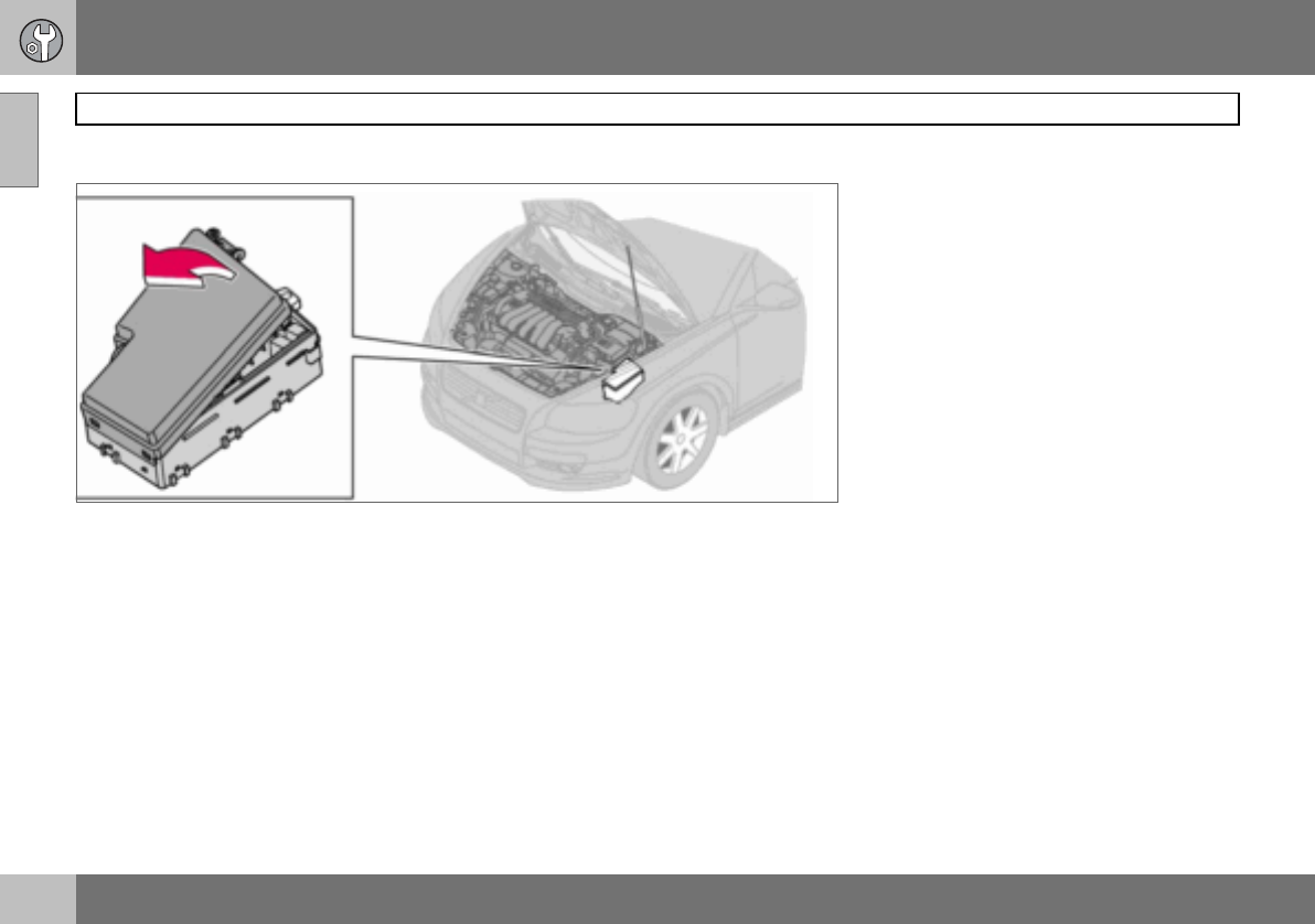
09 Maintenance and service
188
Fuses
09
Relay/fuse box in the engine compartment
The fuse box has 36 fuse positions. Be sure
to replace a blown fuse with a new fuse of
the same colour and amperage.
• Fuses 19–36 are of the "Mini Fuse" type.
• Fuses 7–18 are of the "JCASE" type and
should be replaced by an authorised Volvo
workshop.
• Fuses 1–6 are of the "Midi Fuse" type and
may only be replaced by an authorised
Volvo workshop.
On the inside of the cover are tweezers to as-
sist removing and fitting fuses.
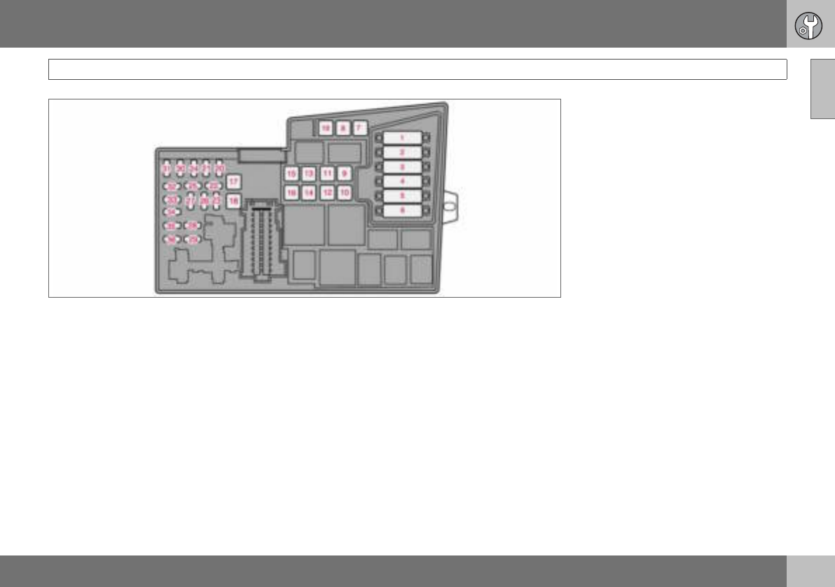
09
09 Maintenance and service
189
Fuses
1. Radiator fan .............................................................................. 50 A
2. Power steering (not 1.6 l engine)........................................ 80 A
3. Supply to passenger compartment fuse box ......................60 A
4. Supply to passenger compartment fuse box ......................60 A
5. Climate control element, additional heater PTC (option)..... 80 A
6. Glow plugs (4-cyl. diesel)................................................... 60 A
Glow plugs (5-cyl. diesel)................................................... 70 A
7. ABS pump ......................................................................... 30 A
8. ABS valves ........................................................................20 A
9. Engine functions................................................................ 30 A
10.Ventilation fan.................................................................... 40 A
11.Headlamp washer.............................................................. 20 A
12.Supply to heated rear window ........................................... 30 A
13.Starter motor relay ............................................................ 30 A
14.Trailer wiring ..................................................................... 40 A
15.Reserve .................................................................................. -
16.Supply to infotainment system .......................................... 30 A
17.Windscreen wipers............................................................ 30 A
18.Supply to passenger compartment fuse box ..................... 40 A
19.Reserve .................................................................................. -
20.Horn ................................................................................. 15 A
21.Fuel-driven additional heater, passenger
compartment heater ......................................................... 20 A
22.Reserve .................................................................................. -
23.Engine control module ECM (5-cyl. petrol)
transmission (TCM) ........................................................... 10 A

09
09 Maintenance and service
190
Fuses
24.Heated fuel filter, PTC element oil trap
(5-cyl. diesel) ..................................................................... 20 A
25.Reserve ...................................................................................-
26.Ignition switch ................................................................... 15 A
27.A/C compressor ................................................................ 10 A
28.Reserve ...................................................................................-
29.Front fog lamp ................................................................... 15 A
30.Engine control module ECM (1.6 l petrol, 2.0 l diesel)...........3 A
31.Voltage regulator, alternator 4-cyl...................................... 10 A
32.Injectors (5-cyl. petrol), lambda-sond (4-cyl. petrol),
charge air cooler (4-cyl. diesel), mass air flow sensor
and turbo control (5-cyl. diesel) ......................................... 10 A
33.Lambda-sond and vacuum pump (5-cyl. petrol),
engine control module (5-cyl. diesel), diesel filter
heater (4-cyl. diesel) .......................................................... 20 A
34.Ignition coils (petrol), injectors (1.6 l petrol),
fuel pump (4-cyl. diesel), pressure switch,
climate control (5-cyl.), glow plugs and
EGR emission control (5-cyl. diesel)...................................10 A
35.Engine sensors for valves, relay coil, air conditioning
PTC element, oil trap (5-cyl. petrol), engine control
module ECM (5-cyl. diesel), canister (petrol), injectors
(1.8/2.0 l petrol, MAF mass air flow sensor
(5-cyl. petrol, 4-cyl. diesel), turbo control (4-cyl. diesel),
pressure switch power steering (1.6 l petrol),
EGR emission control (4-cyl. diesel)................................... 15 A
36.Engine control module ECM (not 5-cyl. diesel), accelerator
pedal position sensor, lambda-sond (5-cyl. diesel) ............ 10 A
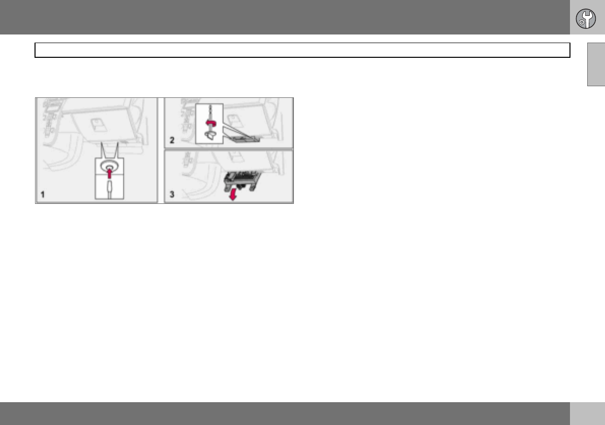
09 Maintenance and service
191
Fuses 09
Relay/fuse box in the passenger
compartment
The fuse box has 50 fuse positions. The fus-
es are located under the glovebox. The box
also provides space for several spare fuses.
Tools for fuse replacement are located in the
relay/fuse box in the engine compartment,
see page 188.
Replacing fuses:
– Remove the interior trim concealing the
fuse box by pressing in the pin in the
centre of the clips (1) about one cm and
then withdrawing the clips.
– Turn the two wing screws (that secure the
fuse box) (2) anticlockwise so that they
detach.
– Lower the fuse box (3) half way. Pull it
towards the seat until it stops. Lower it
completely. The fuse box can be fully
unhooked.
– Close the fuse box in the reverse order.
– Remove the pins from the centre of the
clips. Fit the trim and the clips. Reinsert
the pins into the clips. This expands the
clips and secures the trim.
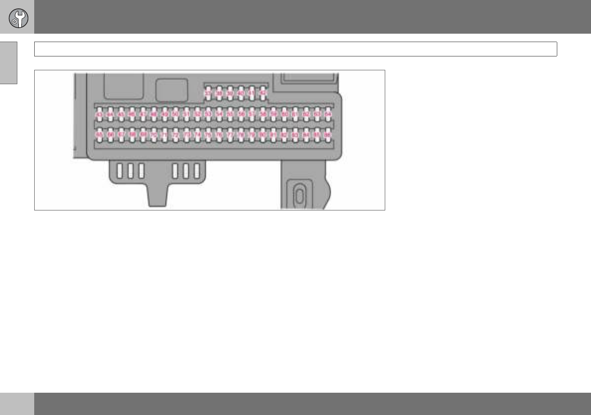
09
09 Maintenance and service
192
Fuses
37.Reserve ...................................................................................-
38.Reserve ...................................................................................-
39.Reserve ...................................................................................-
40.Reserve ...................................................................................-
41.Reserve ...................................................................................-
42.Reserve ...................................................................................-
43.Phone, audio system, RTI (option) .....................................15 A
44.SRS system ....................................................................... 10 A
45.Electrical socket ................................................................ 15 A
46.Passenger compartment, glovebox and courtesy lighting ....5 A
47.Interior lighting ....................................................................5 A
48.Washer, rear window ......................................................... 15 A
49.SRS system ....................................................................... 10 A
50.Reserve .................................................................................. -
51.Parking assistance, additional heater for the passenger
compartment, Bi-Xenon (option) ....................................... 10 A
52.Transmission control module (TCM), ABS system ............... 5 A
53.Power steering .................................................................. 10 A
54.Engine control module ECM (5-cyl.) .................................. 10 A
55.Remote control module, Keyless control module............... 20 A
56.Siren control module......................................................... 10 A
57.Data link connector (DLC), brake light switch .................... 15 A
58.Main beam right, auxiliary lamps relay coil ....................... 7.5 A
59.Main beam, left ................................................................ 7.5 A
60.Seat heating (driver’s side) ................................................ 15 A
61.Seat heating (passenger side) ........................................... 15 A

09
09 Maintenance and service
193
Fuses
62.Sunroof ............................................................................ 20 A
63.Reserve ...................................................................................-
64.Audio system, RTI (option) ...................................................5 A
65.Infotainment system ............................................................5 A
66.Infotainment control module (ICM), climate control ............10 A
67.Reserve ...................................................................................-
68.Cruise control ......................................................................5 A
69.Climate control, rain sensor .................................................5 A
70.Reserve ...................................................................................-
71.Reserve ...................................................................................-
72.Reserve ...................................................................................-
73.Sunroof, overhead console (OHC) rear seatbelt reminder,
autodim mirror.....................................................................5 A
74.Fuel pump relay ................................................................. 15 A
75.Reserve ...................................................................................-
76.Reserve ...................................................................................-
77.Reserve ...................................................................................-
78.Reserve ...................................................................................-
79.Reversing lamp....................................................................5 A
80.Reserve ...................................................................................-
81.Reserve ...................................................................................-
82.Supply to front right door...................................................25 A
83.Supply to front left door .....................................................25 A
84.Power passenger seat ....................................................... 25 A
85.Power driver’s seat............................................................ 25 A
86.Interior lighting, cargo area lighting, power seats,
fuel level display (1.8F) ........................................................ 5 A

194
General ................................................................................................... 196
Audio functions ...................................................................................... 197
Radio functions ...................................................................................... 199
CD functions ..........................................................................................203
Menu structure – audio system ..............................................................205
Phone functions (option) ........................................................................206
Menu structure – phone ......................................................................... 213

10
INFOTAINMENT SYSTEM
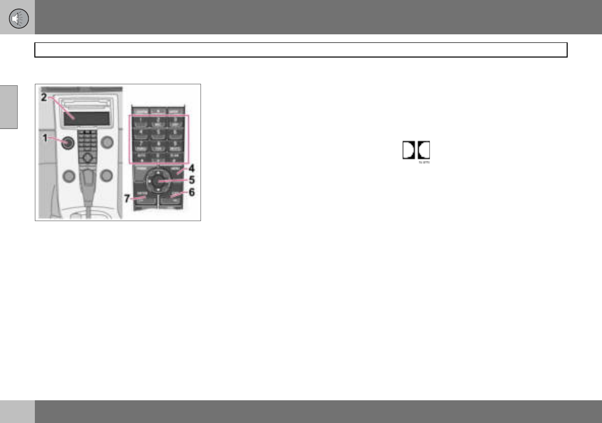
10 Infotainment system
196
General
10
Infotainment system
Infotainment is a system that integrates the
audio system and the phone1. The infotain-
ment system can be easily operated using
the control panel or the steering wheel key-
pad1, see page 54. The display (2) shows
messages and information on the current
function.
Audio system
On/Off
POWER (1) switches the audio system on or
off. If the audio system is active when the ig-
nition key is turned to position 0 then it con-
tinues to be active until the key is removed
from the ignition switch. The audio system is
started automatically the next time the key is
turned to position I.
Menus
Some infotainment system functions are
controlled via a menu system. The current
menu level is shown at the top right of the
display. Menu options are shown in the mid-
dle of the display.
•MENU (4) leads to the menu system.
• Up/down with the navigation button (5)
moves between menu options.
•ENTER (7) selects or activates/deacti-
vates a menu option.
•EXIT (6) leads back one step in the menu
structure. A long press on EXIT will exit
the menu system.
Shortcuts
Menu options are numbered and can also be
selected directly with the keypad (3).
Equipment
The audio system can be equipped with dif-
ferent options and different versions. There
are three audio system versions: Perform-
ance, High Performance and Premium
Sound. FM and AM radio with RDS and CD
player is however included in each version.
Dolby Surround Pro Logic II
Dolby Surround Pro Logic II2 distributes the
two stereo audio channels to left, centre,
right and rear speakers. This provides a more
realistic sound quality than that provided by
standard two-channel stereo.
Dolby Surround Pro Logic II and
the Dolby icon are trademarks of
Dolby Laboratories Licensing Cor-
poration. The Dolby Surround Pro Logic II
System is manufactured under license from
Dolby Laboratories Licensing Corporation.
1Option 2Premium Sound
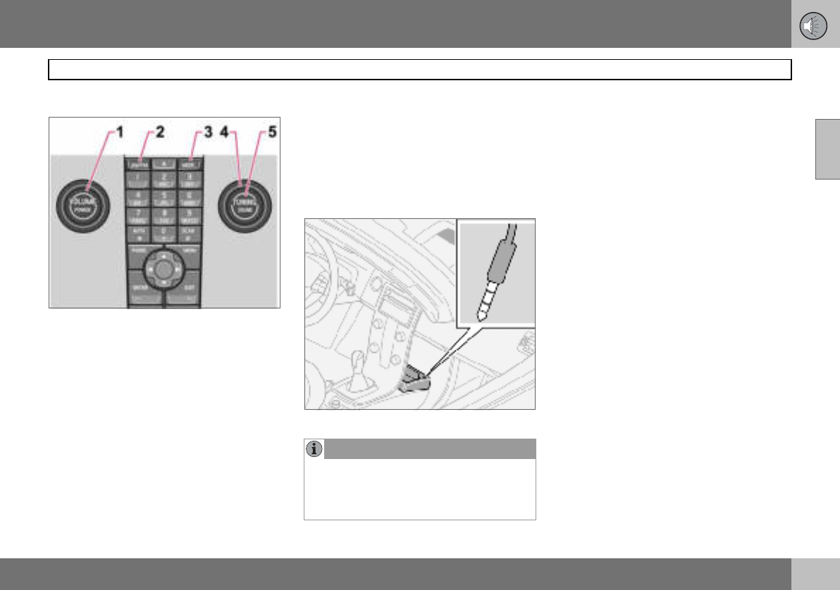
10 Infotainment system
197
Audio functions
10
Audio controls
1. VOLUME – Knob
2. AM/FM – Audio source selection
3. MODE – Audio source selection,
CD/AUX
4. TUNING – Knob
5. SOUND – Button
Volume
Use VOLUME (1) or the steering wheel key-
pad to regulate the volume, see page 54. Au-
dio volume adjusts automatically depending
on vehicle speed, see page 198.
Audio source selection
Repeatedly pressing AM/FM switches be-
tween FM1, FM2 and AM. Repeatedly press-
ing MODE switches between CD and AUX.
AUX1
The AUX input can be used for connecting an
MP3 player for example.
Input for external audio source (AUX) 3.5 mm
Sometimes the AUX external audio source
can be heard at a different volume to the in-
ternal audio sources, e.g. the CD player. If
the audio volume of the external audio
source is too high then the sound quality can
be impaired. Prevent this by adjusting the in-
put volume of the AUX input.
– Set the audio system in AUX mode using
MODE.
– Press MENU and then ENTER.
–Scroll to AUX input Volume and press
ENTER.
– Turn TUNING or press right/left on the
navigation button.
Audio settings
Adjusting audio settings
Repeatedly pressing SOUND browses be-
tween the following alternatives. Adjust by
turning TUNING.
•BASS – Bass level.
•TREBLE – Treble level.
•FADER – Balance between the front and
rear speakers.
•BALANCE – Balance between the left and
right-hand speakers.
1High Performance and Premium Sound.
NOTE
The audio quality may be impaired if the
player is charged while the audio system is
in AUX mode. In which case, avoid charging
the player.
10 Infotainment system
198
Audio functions
10
•CENTRE 1 – Level for centre speaker.
Three channel stereo or Pro Logic II must
be activated before adjustment is possi-
ble. See page 198.
•SURROUND 1 – Level for surround. Pro
Logic II must be activated before adjust-
ment is possible. See page 198.
Surround
Surround settings1 govern the spa-
tial perception of the sound. Set-
tings and activating/deactivating
are separate for each audio source.
The Dolby icon in the display indicates that
Dolby Pro Logic II is active. There are three
different settings for surround sound:
•Pro Logic II
•3 channel
•Off – 2-channel stereo.
Activating/deactivating surround sound
–Press MENU and then ENTER.
– Scroll to Audio settings and press
ENTER.
– Scroll to Surround FM/AM/CD/AUX and
press ENTER.
– Scroll to Pro Logic II 2, 3 channel or Off
and press ENTER.
Equalizer front/rear
The equalizer3 can be used to adjust different
frequency bands separately.
Adjusting the equalizer
– Press MENU and then ENTER.
– Scroll to Audio settings and press
ENTER.
– Scroll to Equalizer front or Equalizer rear
and press ENTER.
– The graphic on the display indicates the
audio level of the frequency in question.
– Adjust the level with TUNING (4) or up/
down on the navigation button. Additional
frequencies can be selected using the left/
right navigation button.
–Use ENTER to save or EXIT to close.
Automatic volume control
The auto volume control function allows the
audio volume to increase as the speed of the
car increases. There are three levels to
choose from4: Low, Medium and High.
Adjusting automatic volume control
– Press MENU and then ENTER.
–Scroll to Audio settings and press
ENTER.
–Scroll to Automatic volume control and
press ENTER.
–Scroll to Low, Medium or High and press
ENTER.
1Premium Sound
2Not available in AM and FM mode.
3Certain audio systems.
4Not Performance Sound.
10 Infotainment system
199
Radio functions
10
Radio controls
1. FM/AM – Wavelength selection
2. Station presets
3. TUNING – Knob for station searches
4. SCAN – Scanning
5. Navigation button – Tuning and menus
6. EXIT – Cancel current function
7. AUTO – Automatic storage of stations
Tuning
Automatic tuning
– Select wavelength using AM/FM (1).
– Give a brief press, left or right, on the
navigation button (5).
Manual tuning
– Select wavelength using AM/FM (1).
– Adjust the frequency by turning
TUNING (3).
Tune into a station with a long press (left or
right) on the navigation button or by using the
steering wheel keypad:
– Hold the right or left side of the navigation
button depressed until the desired fre-
quency appears on the display.
As long as the frequency graphic appears on
the display, searching can be resumed by
briefly pressing the navigation button (left or
right) (5)
Storing stations
Ten station presets can be stored per wave-
length. FM has two memories for presets:
FM1 and FM2. Preset stations are selected
using the preset buttons (2) or the steering
wheel keypad.
Storing stations manually
– Tune into a station.
– Hold a station preset button depressed
until the message Station stored appears
on the display.
Automatic storage of stations
AUTO (7) seeks out the ten strongest radio
stations and stores them automatically in a
separate memory. The function is especially
useful in areas where the radio stations and
their frequencies are unfamiliar.
Starting automatic storage of stations
– Select wavelength using AM/FM (1).
–Hold AUTO (7) depressed until Autostor-
ing... appears on the display.
Once Autostoring... disappears from the dis-
play, the stations are stored. The radio con-
tinues in Auto mode and Auto appears on the
display. The automatically stored presets can
now be selected using the preset buttons (2).
Cancelling automatic storage of sta-
tions
– Press EXIT (6).
Selecting an autostored preset
Allowing the radio to remain in Auto mode
provides access to the autostored presets.
– Briefly press AUTO (7).
Auto appears on the display.
– Press a preset button (2).
The radio remains in Auto mode until it is ex-
ited by a brief press on AUTO (7), EXIT (6) or
AM/FM (1).
10 Infotainment system
200
Radio functions
10
Storing autostored presets in another
memory
An autostored preset can be transferred to
the FM or AM memory.
– Briefly press AUTO (7).
Auto appears on the display.
– Press a preset button.
– Press the button under which the station
will be stored and hold it depressed until
the message Station stored appears on
the display.
The radio exits Auto mode and the stored
station can be selected as a preset.
Scanning
SCAN (4) automatically searches through a
wavelength for strong stations. When a sta-
tion is found, it is played for
approx. eight seconds before scanning is re-
sumed.
Activating/deactivating Scan
– Select wavelength using AM/FM.
–Press SCAN to activate.
SCAN appears on the display. Close using
SCAN or EXIT.
Storing a station
A desired station can be stored as a preset
while Scan is active.
– Press a preset button and hold it de-
pressed until the message Station stored
appears on the display.
Scan is interrupted and the stored station
can be selected as a preset.
RDS functions
Radio Data System – RDS links FM transmit-
ters into a network. An FM transmitter in such
a network sends information that gives an
RDS radio the following functions:
• Automatically switches to a stronger
transmitter if reception in the area is poor.
• Searches for programme form, such as
traffic information or news.
• Receives text information on current radio
programme.
Some radio stations do not use RDS or only
some if its functionality.
Programme functions
In FM mode, the radio can search for stations
with certain programme types. If a required
programme type is located the radio can
switch stations interrupting the audio source
currently in use. For example, if the CD player
is in use, it is paused. The interrupting trans-
mission is played at a preset audio volume,
see page 202. The radio returns to the previ-
ous audio source and audio volume when the
set programme type is no longer broadcast.
The programme functions alarm (ALARM),
traffic information (TP), news (NEWS), and
programme types (PTY) interrupt one anoth-
er in order of priority, where alarm has the
highest priority and programme types has
the lowest. For further programme interrup-
tion settings, see EON and REG on
page 202. The programme functions are
modified via the menu system, see page 196.
Returning to the interrupted audio
source
Press EXIT to return to the interrupted audio
source.
Alarm
This function is used to warn of serious acci-
dents and catastrophes. The alarm cannot
be temporarily interrupted or deactivated.
The message ALARM! appears on the dis-
play when an alarm message is transmitted.
Traffic information – TP
This function allows traffic informa-
tion sent within a set station’s RDS
network to break through. TP indi-
cates that the function is activated.
If the set station can send traffic information
then appears on the display.
Activating/deactivating TP
– Press MENU and then ENTER.
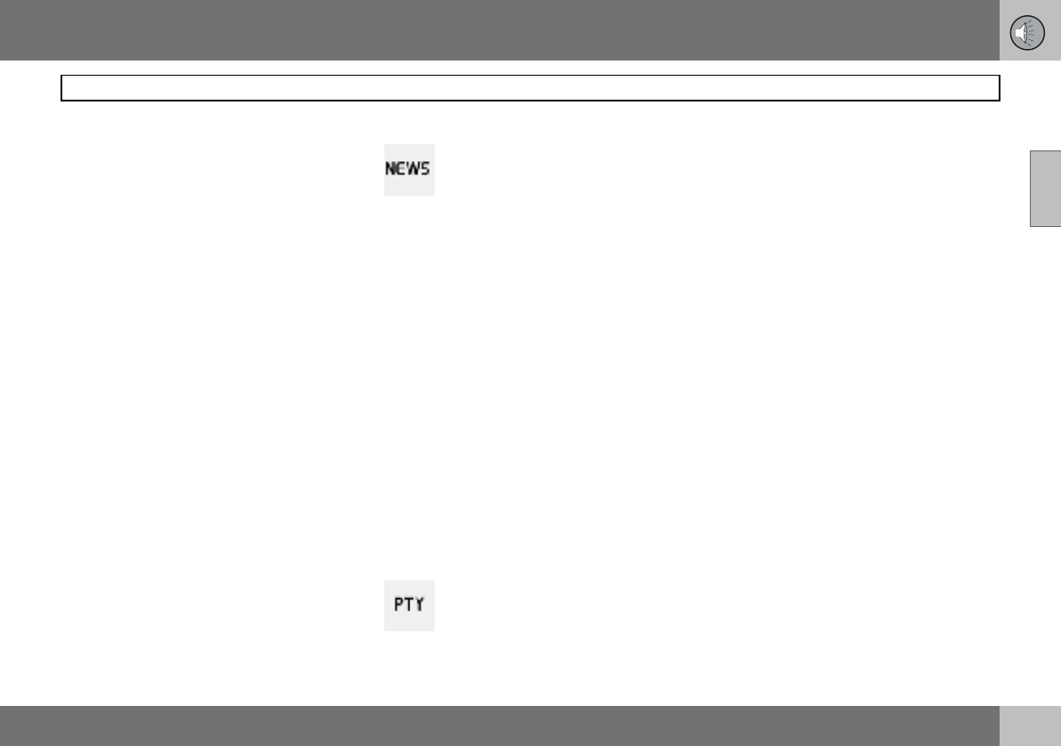
10 Infotainment system
201
Radio functions
10
– Scroll to TP and press ENTER.
TP from current station/all stations
The radio can interrupt with traffic informa-
tion from only the set (current) station or from
all stations.
– Select an FM station.
–Press MENU and then ENTER.
– Scroll to Advanced radio settings and
press ENTER.
– Scroll to TP and press ENTER.
– Scroll to TP Station and press ENTER.
Either TP from current station or
TP from all stations will appear on the dis-
play.
–Press ENTER.
Activating/deactivating TP search
TP search is useful during long journeys
while an audio source other than the radio is
being played. The function automatically
searches for traffic information within differ-
ent RDS networks.
–Press MENU and then ENTER.
– Scroll to Advanced radio settings and
press ENTER.
– Scroll to TP and press ENTER.
– Scroll to TP search and press ENTER.
News
This function allows news broad-
casts within a set station’s RDS
network to break through. The mes-
sage NEWS indicates that the func-
tion is active.
Activating/deactivating News
– Press MENU and then ENTER.
– Scroll to News and press ENTER.
News from current station/all stations
The radio can interrupt with news from only
the set (current) station or from all stations.
– Select an FM station.
– Press MENU and then ENTER.
– Scroll to Advanced radio settings and
press ENTER.
– Scroll to News station and press ENTER.
Either News from current station or
News from all stations will appear on the
display.
– Press ENTER.
Programme types – PTY
The PTY function can be used to
select different programme types,
such as pop music and
serious classic. The PTY symbol
indicates that the function is active. This
function allows programme types broadcast
within a set station’s RDS network to break
through.
Activating/deactivating PTY
– Select FM1 or FM2 with FM/AM.
– Press MENU and then ENTER.
–Scroll to PTY and press ENTER.
–Scroll to Select PTY and press ENTER.
A list of programme types appears: Current
affairs, Information etc. The PTY function is
activated by selecting programme types and
deactivated by clearing all PTYs.
– Select the desired programme types or
Clear all PTY
Search PTY
This function searches the entire wavelength
for the selected programme type.
– Activate PTY.
– Press MENU and then ENTER.
–Scroll to PTY and press ENTER.
–Scroll to Search PTY and press ENTER.
If the radio finds any of the selected pro-
gramme types then the display shows
>| To seek . Press the navigation button to
the right to continue searching for another
broadcast of the selected programme types.
10 Infotainment system
202
Radio functions
10
Display of programme type
The programme type of the current station
can be shown on the display.
Activating/deactivating display
–Press MENU and then ENTER.
– Scroll to PTY and press ENTER.
– Scroll to Show PTY and press ENTER.
Radio text
Some RDS stations transmit information on
programme content, artists, etc. This infor-
mation can be shown on the display.
Activating/deactivating radio text
–Press MENU and then ENTER.
– Scroll to Radio text and press ENTER.
Automatic frequency update – AF
The AF function selects one of the strongest
transmitters for a set station. The radio may
sometimes need to search through the entire
FM wavelength to find a strong transmitter. If
this occurs, the radio mutes and PI Seek
Exit to cancel appears on the display.
Activating/deactivating AF
– Press MENU and then ENTER.
– Scroll to Advanced radio settings and
press ENTER.
– Scroll to AF and press ENTER.
Regional radio programmes – REG
This function causes the radio to
continue with a regional transmitter
even if its signal strength is low.
REG indicates that the function is
active. The regional function is normally de-
activated.
Activating/deactivating REG
– Press MENU and then ENTER.
– Scroll to Advanced radio settings and
press ENTER.
– Scroll to Regional and press ENTER.
Enhanced Other Networks – EON
The EON function is especially useful in ur-
ban areas with many regional radio stations.
It allows the distance between the car and
the radio station transmitter to determine
when programme functions should interrupt
the current audio source.
•Local – interrupts only if the radio station
transmitter is close.
•Distant 1 – interrupts if the station trans-
mitter is far away, even if there is a lot of
static.
•Off – no interruption for programmes from
other transmitters.
Activating/deactivating EON
– Press MENU and then ENTER.
–Scroll to Advanced radio settings and
press ENTER.
–Scroll to EON and press ENTER.
–Scroll to Local, Distant or Off and press
ENTER.
Resetting RDS functions
Resets all radio settings to the original facto-
ry settings.
– Press MENU and then ENTER.
–Scroll to Advanced radio settings and
press ENTER.
–Scroll to Reset all and press ENTER.
Volume control, programme types
The interrupting programme types are heard
at the volume selected for each programme
type. If the volume level is adjusted during
the programme interruption, the new level is
saved until the next programme interruption.
NOTE
Not all radio stations support this function.
1Default/Factory setting.
10 Infotainment system
203
CD functions
10
CD function controls
1. Navigation button – Fast forward/rewind,
track selection and menus
2. CD changer position selection1
3. CD insertion/eject
4. CD insertion/eject slot
5. MODE – Audio source selection CD
and AUX2
6. TUNING – Knob for track selection
Starting playback (CD player)
If a music CD is in the player when the audio
system is in CD mode then playback is start-
ed automatically. Otherwise, load a disc and
change to CD mode by pressing MODE.
Starting playback (CD changer)
If a CD position with a music CD is already
selected when the audio system is activated
then playback starts automatically. Other-
wise change to CD changer mode using
MODE and select a disc with the number
buttons 1–6 or Up/Down on the navigation
button.
Inserting a CD (CD changer)
– Select an empty position with buttons 1–6
or Up/Down on the navigation button.
An empty position is marked on the display.
The text Insert disc shows that a new disc
can be inserted. The CD changer can hold up
to six CDs.
– Insert a CD in the slot of the CD changer.
CD eject
A CD will stay in the ejected position for ap-
prox. 12 seconds. Following which it is re-in-
serted in the player and playback continues.
Eject individual discs by pressing the eject
button (3).
Eject all discs with a long press on the eject
button. The entire magazine is emptied disc
by disc. The message Eject all is shown in
the display.
Pause
If the volume is turned down completely, the
CD player is stopped. The player is restarted
when volume is increased.
Audio files2
The CD player also supports MP3 and WMA
format audio files.
When a CD containing audio files is inserted
into the player the disc’s directory structure
is read in. It may take a while before playback
starts due to the quality of the disc.
Navigation and playback
If a disc containing audio files is inside the
CD player then ENTER leads to the disc’s di-
rectory structure. The directory structure is
navigated in the same way as the audio sys-
tem’s menu structure. Audio files have the
symbol and directories have the
symbol . Start audio file playback with
ENTER.
When the playback of a file is finished the
playback of the other files in the same direc-
tory continues. Directory change takes place
1Option
2High Performance and Premium Sound
NOTE
Certain types of copy-protected audio files
cannot be read by the player.
10 Infotainment system
204
CD functions
10
automatically when all files in the current di-
rectory have been played back.
Press left/right on the navigation button if the
display is not wide enough to show the whole
audio file name.
Fast-wind/change CD tracks and audio
files
Short presses right/left on the navigation
button are used to scroll between CD tracks/
audio files. Long presses are used to fast-
wind CD tracks/audio files. TUNING (or the
steering wheel keypad) can also be used for
this purpose.
Scan CD
This function plays the first ten seconds of
each CD track/audio file. Press SCAN to ac-
tivate. Interrupt with EXIT or SCAN to con-
tinue playback of the current CD track/au-
dio file.
Random
This function plays the tracks in random or-
der. The random CD tracks/audio files can be
scrolled through in the normal way.
Different messages appear on the display
depending on which random function has
been selected.
•RANDOM means that the tracks from only
one music CD are played
•RND ALL means that all tracks on all
music CDs in the CD changer are played.
•RANDOM FOLDER means that the audio
files in a directory on the current CD are
played.
Activating/deactivating (CD player)
– If a normal music CD is being played:
– Press MENU and then ENTER.
– Scroll to Random and press ENTER.
If a disc with audio files is being played:
– Press MENU and then ENTER.
– Scroll to Random and press ENTER.
– Scroll to Folder or Disc and press ENTER.
Activating/deactivating (CD changer)
If a normal music CD is being played:
– Press MENU and then ENTER.
– Scroll to Random and press ENTER.
– Scroll to Single disc or All discs and press
ENTER.
The option All discs only applies to the mu-
sic CDs in the changer.
If a CD with audio files is being played:
– Press MENU and then ENTER.
–Scroll to Random and press ENTER.
–Scroll to Single disc or Folder and press
ENTER.
The function is deactivated when another CD
is selected.
Disc text
If title information is stored on a music CD it
can be shown on the display1.
Activating/deactivating
– Start CD playback.
– Press MENU and then ENTER.
–Scroll to Disc text and press ENTER.
CDs
Using low quality CD discs could result in
poor or non-existent sound.
NOTE
It is only possible to scroll between random
CD tracks on the current disc. 1Only applies to CD changer.
IMPORTANT
Use only standard discs (12 cm in diame-
ter). Do not use CDs with adhesive disc la-
bels. The heat in the CD player may cause
the label to come off, damaging the CD
player.

10 Infotainment system
205
Menu structure – audio system
10
FM menu
1. News
2. TP
3. PTY
4. Radio text
5. Advanced radio settings
6. Audio settings1
AM menu
1. Audio settings1
CD menu
1. Random
2. News
3. TP
4. Disc text
5. Audio settings1
CD changer menu
1. Random
2. News
3. TP
4. Disc text
5. Audio settings1
AUX menu
1. AUX volume
2. News
3. TP
4. Audio settings1
1Certain audio systems.
10 Infotainment system
206
Phone functions (option)
10
Phone system components
10 Infotainment system
207
Phone functions (option)
10
Phone system components
1. Antenna
2. Steering wheel keypad
Most phone system functions can be ac-
cessed via the keypad. See page 208.
3. Microphone
The handsfree microphone is integrated in
the roof console beside the rearview mirror.
4. Centre console control panel
All phone functions (except call volume) can
be regulated via the control panel.
5. Privacy handset (option certain
markets)
6. SIM card reader
General
• Always put traffic safety first.
• If the driver needs to use the privacy
handset, park the car in a safe place first.
• The phone system must be switched off
when the car is refuelled.
• Switch off the system near blasting work.
• Only entrust phone system servicing to an
authorised Volvo workshop.
Emergency calls
Emergency calls to alarm centres can be
made without a SIM card as long as there is
coverage by a GSM operator.
Making an emergency call
– Activate the phone.
– Ring the emergency number that applies
to your region (within EU: 112).
– Press ENTER.
IDIS
(Intelligent Driver Information System) The
IDIS system allows incoming phone calls and
text (SMS) messages to be delayed so that
the driver can concentrate on driving. Incom-
ing calls and text messages can be delayed
five seconds before they are connected.
Missed calls are shown on the display. IDIS
can be deactivated using menu function
5.6.2. See page 214.
SIM card
The phone can only be used with a valid SIM
card (Subscriber Identity Module). The card
is available from various network operators.
Contact your network operator if you experi-
ence difficulties with the SIM card.
Double SIM cards
Many network operators offer two SIM cards
for the same phone number. The extra SIM
card can be used in the car.
Inserting the SIM card
– Switch off the phone and open the glove-
box.
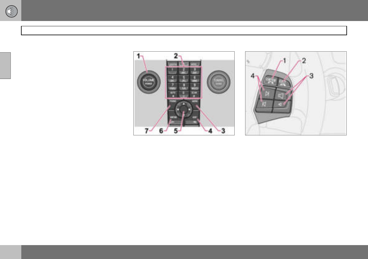
10 Infotainment system
208
Phone functions (option)
10
– Pull out the SIM card holder (1) in the SIM
card reader.
– Position the SIM card in the holder with
the metal surface visible. The bevelled
edge of the SIM card should align with the
bevel of the SIM card holder.
– Carefully press in the SIM card holder.
Menus
Page 196 describes how to control phone
functions with the menu system.
Traffic safety
For safety reasons, parts of the phone menu
system cannot be accessed at speeds in ex-
cess of 8 km/h. Only activities started in the
menu system can be completed. The speed
limiter can be deactivated using menu func-
tion 5.6.1 Menu lock, see page 213.
Phone controls
Centre console control panel
1. VOLUME – Control the background vol-
ume from the radio, for example, during a
call.
2. Number and letter buttons
3. MENU – Opens the main menu
4. EXIT – End/refuse calls, clear entered
characters
5. Navigation button – Scroll in menus
and character rows
6. ENTER – Accept calls, activate the
phone from standby mode
7. PHONE – On/off and standby mode
Steering wheel keypad
When the phone is active, the steering wheel
keypad is locked to phone functions. To con-
trol the audio system, the phone must be in
standby mode.
1. ENTER – Works the same as on the
control panel.
2. EXIT – Works the same as on the
control panel
3. Call volume – Increase/decrease
4. Navigation buttons – Scroll in menus

10 Infotainment system
209
Phone functions (option)
10
On/Off
A handset appears in the display when the
phone system is active or in standby mode. If
the ignition key is turned to position 0 when
the phone is in one of these modes, the
phone automatically resumes this mode the
next time the key is turned to position I or II.
Activating the phone system
Phone system functions can only be used
when the phone is in active mode.
–Press PHONE.
– Enter the PIN code (if necessary) and
press ENTER.
Deactivating the phone system
No calls can be received when the phone is
deactivated.
–Hold PHONE depressed until the phone is
activated.
Standby
In standby mode, the audio system can be in
use while calls are received. However, it is
not possible to make calls when in standby
mode.
Putting the phone in standby mode
The phone must first be in active mode be-
fore it can be put in standby mode.
– Press PHONE or EXIT.
Activating from standby mode
– Press PHONE.
Making and receiving calls
If the privacy handset is raised when a phone
call is started, the sound will come from the
handsfree system. For information on switch-
ing between privacy handset and handsfree
during a call, see page 211.
To c a l l
– Activate the phone system (if necessary).
– Dial the number or use the phone book,
see page 211.
– Press ENTER or lift the handset. Release
the handset by pressing it down.
Receiving a call
For Auto answer, see menu option 4.3,
page 213.
– Press ENTER or lift the handset. Release
the handset by pressing it down.
Ending a call
– Press EXIT or hang up the handset.
Refusing a call
– Press EXIT.
Call waiting
A two-tone signal during a phone call indi-
cates that there is another incoming call. An-
swer? appears on the display. The call can
be refused or taken in the normal manner. If
the incoming call is taken, the previous call is
put on hold.
Putting a call on hold/resuming a call
– Press MENU.
–Scroll to Hold or Hold off and press
ENTER.
Dialling a third party
– Put the call on hold.
– Dial the number of the third party.
Switching between calls
– Press MENU.
–Scroll to Swap and press ENTER.
Starting a conference call
A conference call consists of at least three
parties that can talk to one another. Once a
conference call has been initiated, no more
parties can be connected. All calls are ended
when a conference call is ended.
– Start two phone calls
– Press MENU.
–Scroll to Join and press ENTER.
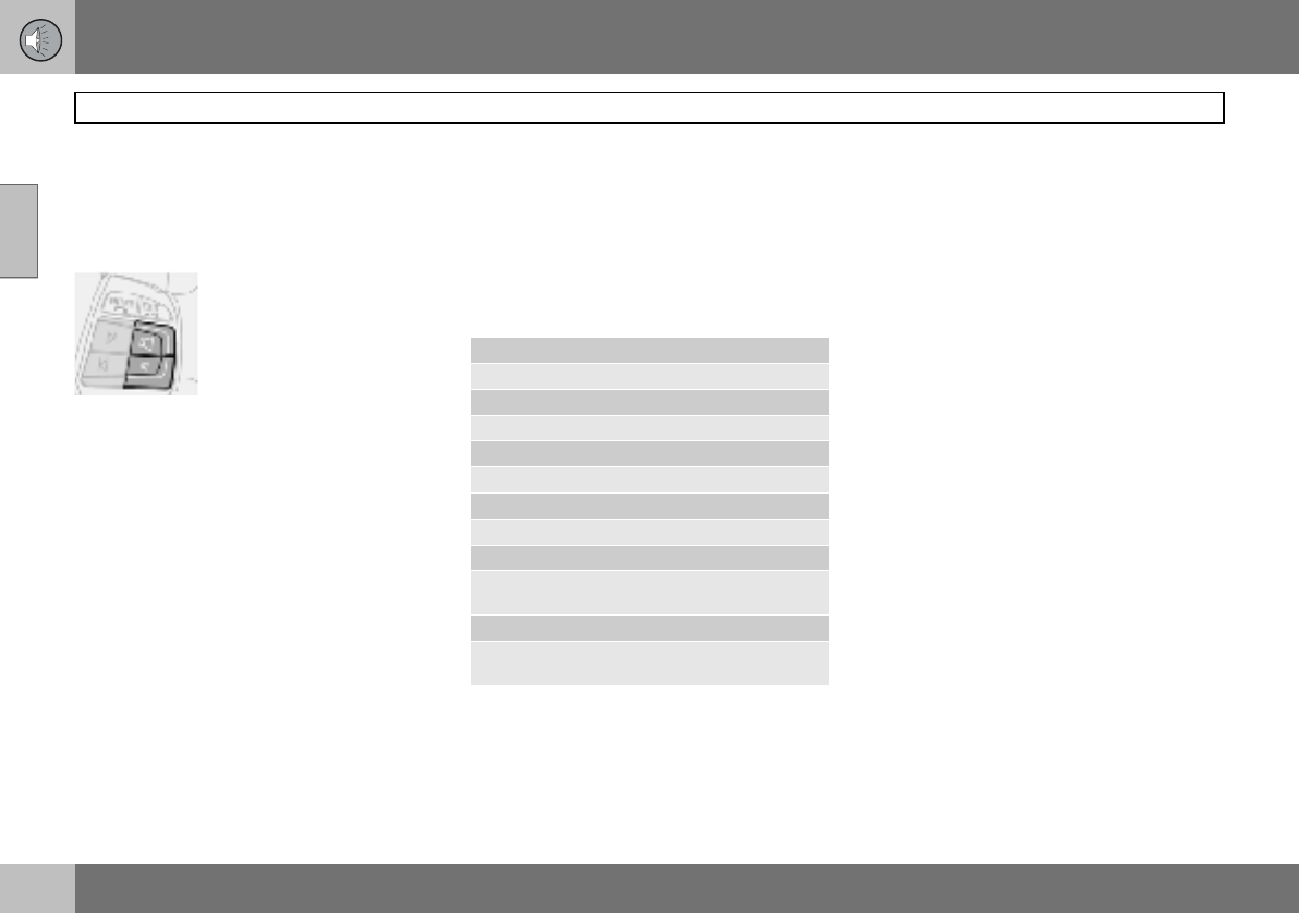
10 Infotainment system
210
Phone functions (option)
10
Volume
The phone uses the driver’s door or centre
speaker1.
Call volume
Call volume is regulated
with the buttons of the
steering wheel keypad.
If the privacy handset is
used, volume is regulated
with a wheel on the side of
the handset.
Audio system volume
Audio system volume is temporarily lowered
during a phone call. Once the call is ended
the previous volume is resumed. If the vol-
ume is regulated during the call, the new lev-
el is retained once the call is ended. Sound
can also be automatically muted during a
phone call, see menu 5.5.3, page 214. This
function is only available with the Volvo inte-
grated phone system.
Entering text
Text is entered using the phone keypad.
– Press the button with the desired charac-
ter - once for the first character on the
button, twice for the second, etc. See
table.
– Press 1 for a space. If two characters in a
row are to be entered using the same
button, press * or wait a few seconds.
A short press on EXIT deletes an input char-
acter. A long press on EXIT will clear all en-
tered characters.
Handling numbers
Calling the last number dialled
The phone automatically stores the last
phone numbers dialled.
– Press ENTER.
– Scroll to a number and press ENTER.
Phone book
If the phone book contains a live caller’s con-
tact information then this is shown in the dis-
play. Contact information can be stored on
the SIM card and in the phone.
Storing contacts in the phone book
– Press MENU.
–Scroll to Phone book and press ENTER.
–Scroll to New number and press ENTER.
– Enter a name and press ENTER.
– Enter a number and press ENTER.
–Scroll to SIM card or Phone and press
ENTER.
Searching for contacts in the phone
book
Use the down arrow of the navigation button
instead of MENU for direct access to the
Search menu.
– Press MENU.
–Scroll to Phone book and press ENTER.
1Premium Sound.
1space 1- ? ! , . : " ' ( )
2a b c 2 ä å à æ ç
3d e f 3 è é
4g h i 4 ì
5j k l 5
6m n o 6 ñ ö ò Ø
7p q r s 7 ß
8t u v 8 ü ù
9w x y z 9
*Used if two characters are to be
ended with the same button.
0+ 0 @ * # & $ £ / %
#Switch between upper and lower
case.
10 Infotainment system
211
Phone functions (option)
10
– Scroll to Search and press ENTER.
– Enter the first few letters of the item and
press ENTER, or simply press ENTER.
– Scroll to an item and press ENTER.
Copying entries between the SIM card
and Phone book
–Press MENU.
– Scroll to Phone book and press ENTER.
– Scroll to Copy all and press ENTER.
– Scroll to SIM to phone or Phone to SIM
and press ENTER.
Deleting contacts from the phone book
–Press MENU.
– Scroll to Phone book and press ENTER.
– Scroll to Search and press ENTER.
– Enter the first few letters of the item and
press ENTER, or simply press ENTER.
– Scroll to the item to be erased and press
ENTER.
– Scroll to Erase and press ENTER.
Erase all contacts
–Press MENU.
– Scroll to Phone book and press ENTER.
– Scroll to Erase SIM or Erase phone and
press ENTER.
If required, enter phone code. The factory-
set default code is 1234.
Speed dial
A keypad button (1- 9) can be used as a
speed dial number for a contact in the phone
book.
– Press MENU.
– Scroll to Phone book and press ENTER.
– Scroll to One-key dial and press ENTER.
– Scroll to Select numbers and press
ENTER.
– Scroll to the digit of the keypad button for
the speed dial number and press ENTER.
– Enter the first few letters of the item and
press ENTER, or simply press ENTER.
– Scroll to an item and press ENTER.
– Hold EXIT depressed to leave the menu
system.
Calling using speed dial
– Hold the desired keypad button for
approx. two seconds or briefly press the
button and then ENTER.
To use the speed dial function One-key dial
must be activated in the Phone book menu,
see page 215.
Calling from the phone book
– Press MENU.
–Scroll to Phone book and press ENTER.
All contacts in the phone book memory are
displayed. The number of contacts displayed
can be reduced by entering part of the con-
tact’s name.
– Scroll to a contact and press ENTER.
Functions during a call
Several functions are available during a call.
Some functions can only be used when a call
is on hold.
Press MENU to access the In-call menu and
scroll to one of the following alternatives:
•Mute/Mute off – Mute mode.
•Hold/Hold off – Put a call on hold or
resume a call.
•Handsfree/Handset – Use handsfree or
the privacy handset.
•Phone book – Access the phone book.
•Join – Conference calling (available if
more than three parties are connected)
NOTE
When the phone is switched on, it takes a
while before speed dialling is available.
NOTE
Press ENTER to dial.
10 Infotainment system
212
Phone functions (option)
10
•Swap – Switch between two calls (availa-
ble if up to three parties are connected).
SMS – Short Message Service
Reading SMS
–Press MENU.
– Scroll to Messages and press ENTER.
– Scroll to Read and press ENTER.
– Scroll to a message and press ENTER.
The message text is shown in the display.
Additional selections can be made by press-
ing ENTER. Hold EXIT depressed to leave
the menu system.
Writing and sending
–Press MENU.
– Scroll to Messages and press ENTER.
– Scroll to Write new and press ENTER.
– Enter text and press ENTER.
– Scroll to Send and press ENTER.
– Enter a phone number and press ENTER.
IMEI number
In order to block a phone the network provid-
er must be advised of the phone’s IMEI
number. This is a 15 digit serial number that
is programmed in the phone. Dial *#06# to
show this number in the display. Write it
down and keep it in a safe place.
Specifications
Output 2 W
SIM card Small
Memory entries 2551
1The capacity of the SIM card’s memory varies
depending on the subscription.
SMS (Short Message
Service) Ye s
Data/Fax No
Dualband (900/1800 MHz) Ye s

10 Infotainment system
213
Menu structure – phone
10
Overview
1. Call register
1.1. Missed calls
1.2. Received calls
1.3. Dialled no.
1.4. Erase list
1.4.1. All calls
1.4.2. Missed calls
1.4.3. Received calls
1.4.4. Dialled no.
1.5. Call duration
1.5.1. Last call
1.5.2. Call count
1.5.3. Total time
1.5.4. Reset timers
2. Messages
2.1. Read
2.2. Write
2.3. Message sett
2.3.1. SMSC number
2.3.2. Validity time
2.3.3. Message type
3. Phone book
3.1. New number
3.2. Search
3.3. Copy all
3.3.1. SIM to phone
3.3.2. Phone to SIM
3.4. One-key dial
3.4.1. Active
3.4.2. Select numbers
3.5. Erase SIM
3.6. Erase phone
3.7. Memory status
4. Call options
4.1. Send my no.
4.2. Call waiting
4.3. Auto answer
4.4. Auto re-dial
4.5. Diversions
4.5.1. All calls
4.5.2. When engag.
4.5.3. Not answered
4.5.4. Not reachable
4.5.5. Fax calls
4.5.6. Data calls
4.5.7. Cancel all
5. Phone sett.
5.1. Network
5.1.1. Auto
5.1.2. Manual select
5.2. Language
5.2.1. English UK
5.2.2. English US
5.2.3. Español
5.2.4. Français CAN
5.2.5. Français FR
5.2.6. Italiano
5.2.7. Nederlands
5.2.8. Português BR
5.2.9. Português P
5.2.10. Suomi
5.2.11. Svenska
5.2.12. Dansk
5.2.13. Deutsch
5.3. SIM security
5.3.1. On
5.3.2. Off
5.3.3. Auto
5.4. Edit codes
5.4.1. PIN code
5.4.2. Phone code

10 Infotainment system
214
Menu structure – phone
10
5.5. Sounds
5.5.1. Ring volume
5.5.2. Ring signal
5.5.3. Mute radio
5.5.4. Msg. beep
5.6. Traff. safety
5.6.1. Menu lock
5.6.2. IDIS
5.7. Factory sett.
Description of menu options
1. Call register
1.1. Missed calls
List of missed calls. You can choose to call,
erase or store the number in the phone book.
1.2. Received calls
List of received calls. You can choose to call,
erase or store the number in the phone book.
1.3. Dialled no.
List of dialled numbers. You can choose to
call, erase or store the number in the phone
book.
1.4. Erase list
Erase the lists found in the menus 1.1, 1.2
and 1.3 as below.
1.4.1. All
1.4.2. Missed
1.4.3. Received
1.4.4. Dialled no.
1.5. Call duration
Duration of all calls or of the most recent call.
The phone code is required to reset the call
timer (see menu 5.4).
1.5.1. Last call
1.5.2. Call count
1.5.3. Total time
1.5.4. Reset timers
2. Messages
2.1. Read
Received text messages. Select whether to
erase, forward, change or save the entire
message or parts of it.
2.2. Write
Write a message using the keypad. Choose
whether to save or send it.
2.3. Message sett
Enter the number (SMSC number) of the
message centre to which messages are to be
transferred as well as how long they are to be
saved at the message centre. Contact your
network operator for information on message
settings. Normally, these settings should not
be altered.
2.3.1. SMSC number
2.3.2. Validity time
2.3.3. Message type
3. Phone book
3.1. New number
Store names and phone numbers in the
phone book, see page 210.
3.2. Search
Search for a name in the phone book.

10 Infotainment system
215
Menu structure – phone
10
3.3. Copy all
Copy phone numbers and names from the
SIM card to the phone memory.
3.3.1. From SIM to phone memory
3.3.2. From phone to SIM memory
3.4. One-key dial
A number stored in the phone book can be
stored as a speed dial number.
3.5. Erase SIM
Erase the entire SIM card memory.
3.6. Erase phone
Erase the entire phone memory.
3.7. Memory status
Shows how many positions are occupied in
the SIM card and phone memory. The table
shows how many of the total number of posi-
tions are occupied, e.g. 100 (250).
4. Call options
4.1. Send my no.
Displays or hides your phone number to/from
the person you call. Contact your network
operator regarding ex-directory numbers.
4.2. Call waiting
Be alerted during a phone call that there is
another incoming call.
4.3. Auto answer
Automatically answers incoming calls.
4.4. Auto re-dial
Calls a previously engaged number.
4.5. Diversions
Choose when and what type of calls are to
be diverted to a specified phone number.
4.5.1. All calls (this setting only applies
during the call in progress).
4.5.2. When engag.
4.5.3. Not answered
4.5.4. Not reachable
4.5.5. Fax calls
4.5.6. Data calls
4.5.7. Cancel all
5. Phone settings
5.1. Network
Choose a network automatically or manually.
The selected network is shown in the display
in the phone’s basic mode.
5.1.1. Auto
5.1.2. Manual select
5.2. Language
Select the phone language.
5.2.1. English UK
5.2.2. English US
5.2.3. Español
5.2.4. Français CAN
5.2.5. Français FR
5.2.6. Italiano
5.2.7. Nederlands
5.2.8. Português BR
5.2.9. Português P
5.2.10. Suomi
5.2.11. Svenska
5.2.12. Dansk
5.2.13. Deutsch
5.3. SIM security
Select if the PIN code should be on, off or if
the phone should automatically give the PIN
code.
5.3.1. On
5.3.2. Off
5.3.3. Auto
5.4. Edit codes
Change PIN or phone code. Write the codes
down and keep them in a safe place.
5.4.1. PIN code
5.4.2. Phone code. The factory-set phone
code 1234 is used until you change
to your own code. The phone code
is used to reset the call timer.
5.5. Sounds
5.5.1. Volume. Adjust the ring tone
volume.

10 Infotainment system
216
10
5.5.2. Ring signal. There are seven
different ring tones.
5.5.3. Mute radio. On/Off
5.5.4. Msg. beep
5.6. Traffic safety
5.6.1. Menu lock. Deactivating the menu
lock allows access to the entire
menu while driving.
5.6.2. IDIS. If the IDIS function is deacti-
vated, incoming calls are not
delayed, regardless of the driving
situation.
5.7. Factory sett.
Reset the system’s factory settings.

10 Infotainment system
217
10

218
Type designation ....................................................................................220
Dimensions and weights ........................................................................221
Engine specifications .............................................................................224
Engine oil ................................................................................................226
Fluids and lubricants ..............................................................................230
Fuel .........................................................................................................232
Catalytic converter .................................................................................234
Electrical system ....................................................................................235
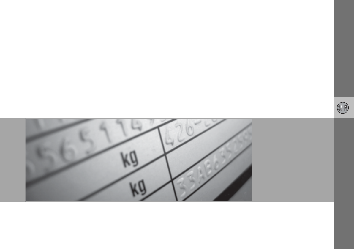
11
SPECIFICATIONS
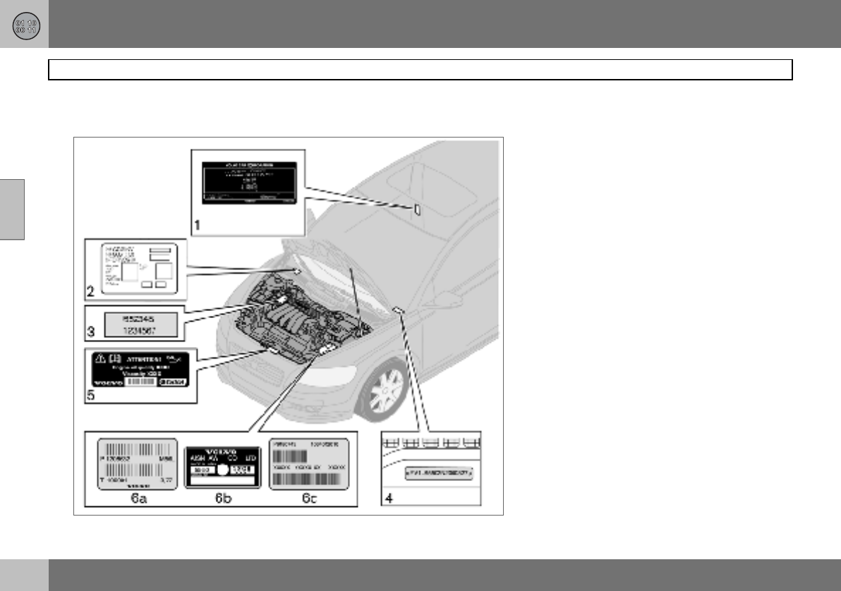
11 Specifications
220
Type designation
11
Knowing the car’s type designation, vehicle
identification and engine numbers can facili-
tate all contact with a Volvo dealer regarding
the car and when ordering spare parts and
accessories.
1. Type designation, vehicle identification
number, maximum permissible weights,
codes for colour and upholstery and type
approval number.
2. Decal for parking heater.
3. Engine type designation, component
and serial number.
4. VIN number (type and model year des-
ignation plus chassis number).
5. Decal for engine oil.
6. Gearbox type designation and serial
number:
(a) manual gearbox
(b), (c) automatic gearbox
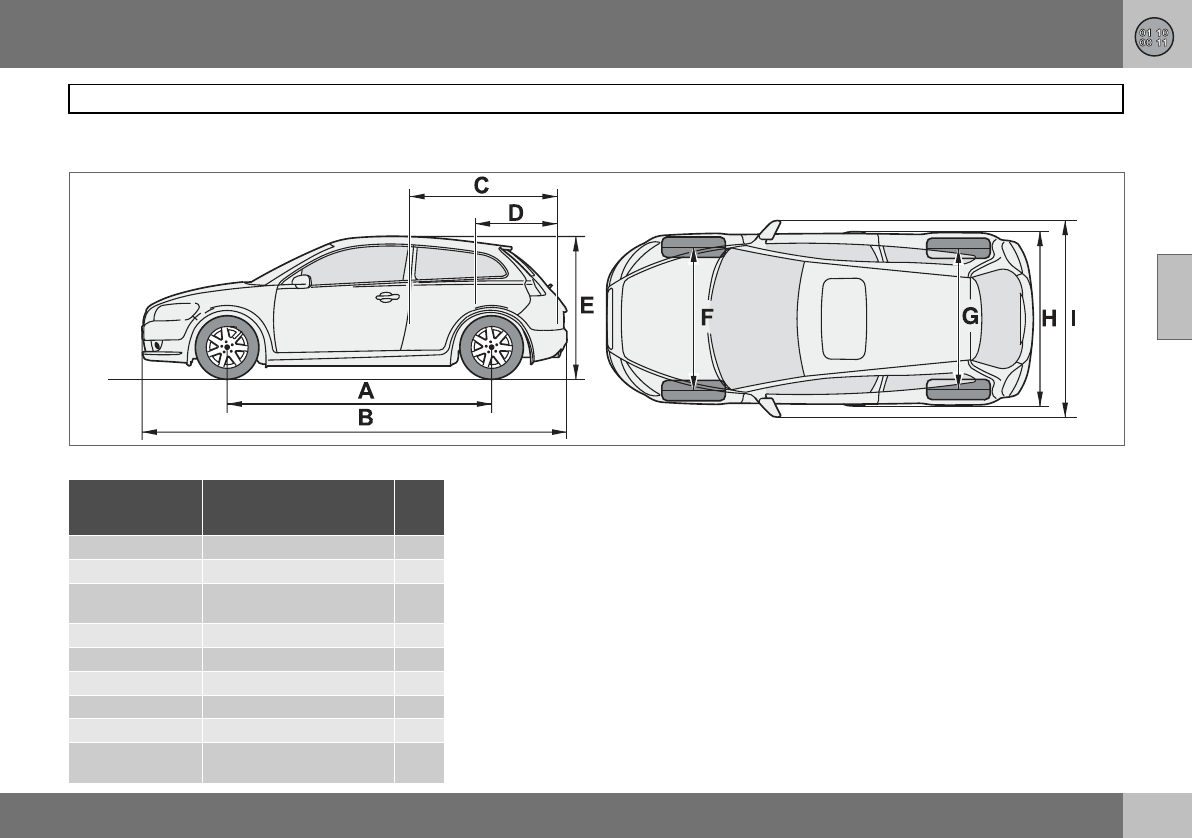
11 Specifications
221
Dimensions and weights
11
Dimensions
Position in
illustration Dimensions cm
AWheelbase 264
BLength 425
CLoad length, floor, folded
seat 149
DLoad length, floor 66
EHeight 145
FFront track 155
GRear track 154
HWidth 178
IWidth including door
mirrors 204
G015593
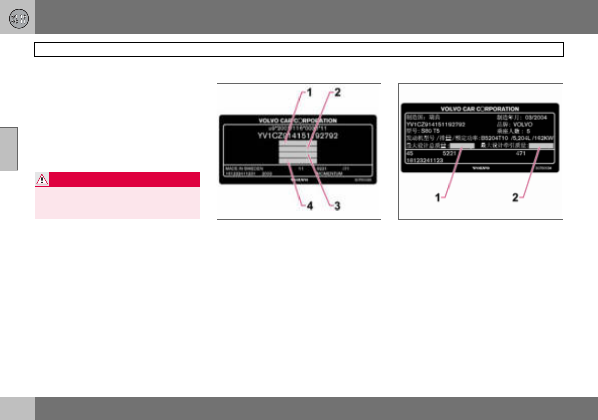
11 Specifications
222
Dimensions and weights
11
Weights
Kerb weight includes the driver, the fuel tank
90 % full and all fluids. The weight of passen-
gers and accessories, such as a towbar, tow-
ball load (when a trailer is hitched, see table),
load carriers, and space box etc. influences
the payload and must not be included in the
kerb weight. Permitted weight (in addition to
driver) = Gross vehicle weight – Kerb weight.
See decal location on page 220.
1. Gross vehicle weight
2. Max. train weight (car+trailer)
3. Max. front axle load
4. Max. rear axle load
Only for China
1. Gross vehicle weight
2. Maximum trailer weight
Maximum load: See registration document.
WARNING
The car’s driving characteristics change de-
pending on how heavily it is loaded and how
the load is distributed.
11 Specifications
223
Dimensions and weights
11
Max. roof load: 75 kg
Maximum
braked trailer
weight kg
Maximum
towball
load kg
1.6 1200 75
1.6D 1300
1.8 1300
1.8F 1300
2.0 1350
others 1500
Maximum unbraked
trailer weight kg
Maximum
towball load
kg
700 50
11 Specifications
224
Engine specifications
11
Engine type designation, component and
serial number can be read on the engine,
see page 220.
1.6 1.8 1.8F 2.0 2.4i T5
Engine designation B4164S3 B4184S11 B4184S8 B4204S3 B5244S4 B5254T3
Output (kW/rpm) 74/6000 92/6000 92/6000 107/6000 125/6000 162/5000
(hp/rpm) 100/6000 125/6000 125/6000 145/6000 170/6000 220/5000
To rq u e ( N m / r p m ) 150/4000 165/4000 165/4000 185/4500 230/4400 320/1500–4800
No. of cylinders 444455
Bore (mm) 79 83 83 87 83 83
Stroke (mm) 81.4 83.1 83.1 83 90 93.2
Swept volume (litres) 1.60 1.80 1.80 1.99 2.44 2.52
Compression ratio 11.0:1 10.8:1 10.8:1 10.8:1 10.3:1 9.0:1
11 Specifications
225
Engine specifications
11
Engine type designation, component and
serial number can be read on the engine,
see page 220.
1.6D 2.0D D5 D5
Engine designation D4164T D4204T D5244T91D5244T8
Output (kW/rpm) 80/4000 100/4000 120/5500 132/4000
(hp/rpm) 109/4000 136/4000 163/5500 180/4000
To rq u e ( N m / r p m ) 240/- 320/2000 340/1750–2750 350/1750–3250
No. of cylinders 4 4 5 5
Bore (mm) 75 85 81 81
Stroke (mm) 88.3 88 93.2 93.2
Swept volume (litres) 1.56 2.00 2.40 2.40
Compression ratio 18.3:1 18.5:1 17.0:1 17.0:1
1Belgium
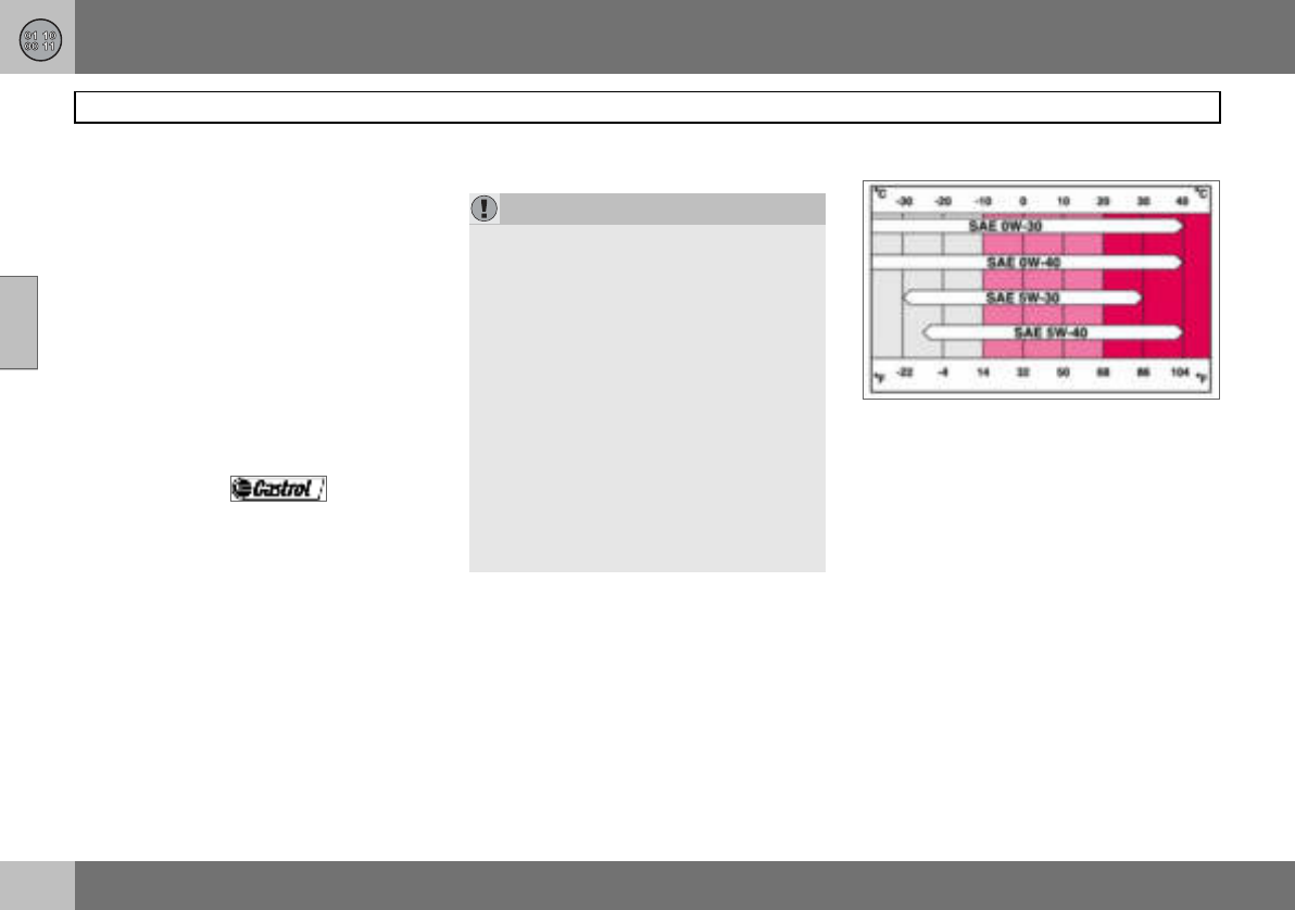
11 Specifications
226
Engine oil
11
Adverse driving conditions
Check the oil level more frequently for long
journeys:
• towing a caravan or trailer
• in mountainous regions
• at high speedsin temperatures colder than
–30 C or hotter than +40 C.
Also check the oil level more often if the car
is often driven short distances (less than
10 km) when temperatures are low
(below+5 C).
This can produce abnormally high oil temper-
ature or oil consumption.
Volvo recommends oil products.
Viscosity chart
IMPORTANT
In order to fulfil the requirements for the en-
gine’s service intervals all engines are filled
with a specially adapted synthetic engine oil
at the factory. The choice of oil has been
made very carefully with regard to service
life, starting characteristics, fuel consump-
tion and environmental impact. An ap-
proved engine oil must be used in order that
the recommended service intervals can be
applied. Only use a prescribed grade of oil
(see the engine compartment decal) for
both filling and oil change, otherwise you
will risk affecting service life, starting char-
acteristics, fuel consumption and environ-
mental impact. Volvo Car Corporation
disclaims all warranty liability if engine oil of
the prescribed grade and viscosity is not
used.
11 Specifications
227
Engine oil
11
Oil decal The following applies when this adjacent oil
decal is fitted in the car’s engine compart-
ment. See location on page 220.
Oil grade: ACEA A3/B3/B4
Viscosity: SAE 0W–30
When driving under adverse conditions, use
ACEA A5/B5 SAE 0W-30.
Engine variant
Filling volume
between MIN–MAX
(litres)
Volume1
(litres)
2.4i B5244S4 1.3 5.8
T5 B5254T3
1Including filter change.
11 Specifications
228
Engine oil
11
Oil decal The following applies when this adjacent oil
decal is fitted in the car’s engine compart-
ment. See location on page 220.
Oil grade: WSS-M2C913-B
Viscosity: SAE 5W–30
When driving under adverse conditions, use
ACEA A5/B5 SAE 0W-30.
Engine variant
Filling volume
between MIN–MAX
(litres)
Volume1
(litres)
1.6 B4164S3 0.75 4.0
1.8 B4184S11 4.3
1.8F B4184S8
2.0 B4204S3
1.6D D4164T 1.0 3.7
2.0D D4204T 2.0 5.5
1Including filter change.
11 Specifications
229
Engine oil
11
Oil decal The following applies when this adjacent oil
decal is fitted in the car’s engine compart-
ment. See location on page 220.
Oil grade: ACEA A5/B5
Viscosity: SAE 0W–30
Engine variant
Filling volume
between MIN–MAX
(litres)
Volume1
(litres)
D5 D5244T8 1.5 6
D5 D5244T92
1Including filter change
2Belgium
NOTE
Under normal driving conditions the gear-
box oil does not need changing during its
service life. However, it may be necessary
under adverse driving conditions, see
page 226.
11 Specifications
230
Fluids and lubricants
11
Fluid System Volume Recommended oil grade
Gearbox oil 1.6 Manual 5-speed 2.1 litres Transmission fluid: WSD-M2C200-C
1.8 Manual 5-speed 1.9 litres
1.6D Manual 5-speed 1.9 litres
1.8F Manual 5-speed 1.9 litres
2.0 Manual 5-speed 1.9 litres
2.0D Manual 5-speed 2.2 litres Transmission fluid: WSS-M2C200-C3
2.0D Manual 6-speed 1.7 litres Transmission fluid: WSD-M2C200-C
2.4D Automatic gearbox 7.75 litres Transmission fluid: JWS 3309
D5 Automatic gearbox 7.75 litres Transmission fluid: JWS 3309
2.4i Manual 5-speed 2.1 litres Transmission fluid: MTF 97309-10
2.4i Automatic gearbox 7.75 litres Transmission fluid: JWS 3309
T5 Manual 6-speed 2.0 litres Transmission fluid: MTF 97309-10
T5 Automatic gearbox 7.75 litres Transmission fluid: JWS 3309
Coolant 5-cyl. Petrol, manual gearbox 9.5 litres Coolant with corrosion inhibitor mixed with
water, see packaging. The thermostat starts
opening at:
90 ºC in petrol engines, and at 82 ºC in diesel
engines.
petrol engine (1.6) 82 ºC
diesel engine (1.6D) 83 ºC
5-cyl. Petrol, automatic gearbox 10.0 litres
5-cyl. Diesel (D5) 11.0 litres
4-cyl. Petrol (1.8, 1.8F and 2.0) 7. 5 l i t r e s
4-cyl. Diesel (2.0D) 9.5 litres
4-cyl. Petrol (1.6) 6.2 litres
4-cyl. Diesel (1.6D) 7. 2 l i t r e s
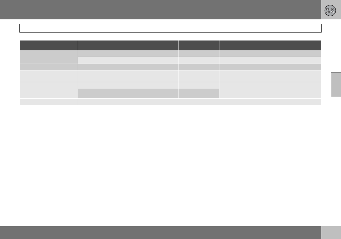
11 Specifications
231
Fluids and lubricants
11
Air conditioning1180–200 grams Compressor oil PAG
500–600 grams Refrigerant R134a (HFC134a)
Brake fluid 0.6 litres DOT 4+
Power steering 0.8–0.9 litres Power steering fluid: WSS M2C204-A2 or equiv-
alent product with same specifications.
Washer fluid 4-cyl. Petrol/Diesel 4.0 litres Use a washer antifreeze recommended by Volvo,
mixed with water for temperatures below
freezing.
5-cyl. Petrol /Diesel 6.5 litres
Fuel tank See page 232.
1Weights can vary depending on the engine variant. Contact an authorised Volvo workshop for the correct information.
Fluid System Volume Recommended oil grade
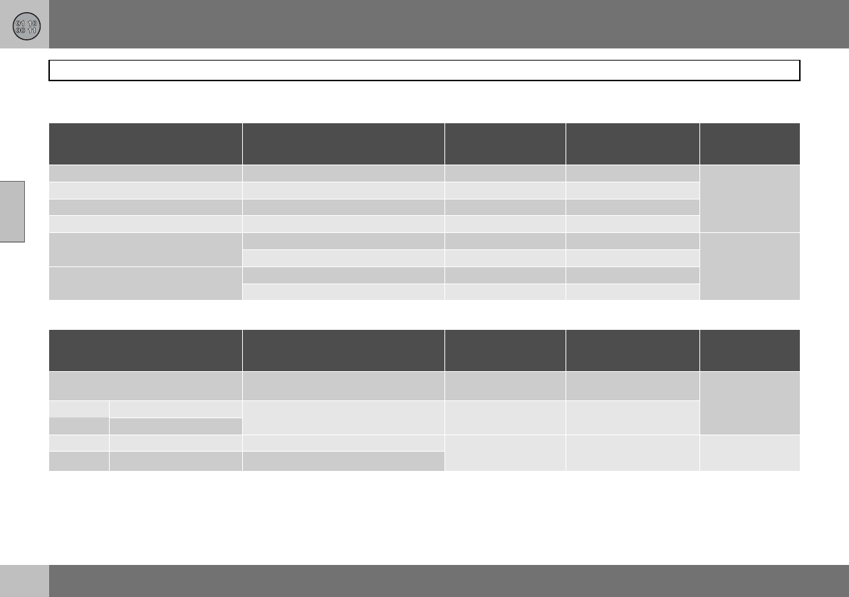
11 Specifications
232
Fuel
11
Consumption, emissions and volume
Engine Gearbox Consumption
litre/100 km
Emissions of CO2
(g/km)
Tank volume
(litres)
1.6 B4164S3 Manual 5-speed (IB5) 7. 0 167 55
1.8 B4184S11 Manual 5-speed (MTX75) 7. 3 174
1.8F B4184S8 Manual 5-speed (MTX75) 7. 3 174
2.0 B4204S3 Manual 5-speed (MTX75) 7. 3 174
2.4i B5244S4 Manual 5-speed (M56H) 8.4 200 62
Automatic gearbox (AW55-51) 9.0 214
T5 B5254T3 Manual 6-speed (M66) 8.7 208
Automatic gearbox (AW55-51) 9.4 224
Engine Gearbox Consumption
litre/100 km
Emissions of CO2
(g/km)
Tank volume
(litres)
1.6D D4164T (EURO3)
(EURO4) Manual 5-speed (MTX75) 4.9 129 52
2.0D D4204T (EURO3) Manual 6-speed (MMT6) 5.7 151
(EURO4)
D5 D5244T8 Automatic gearbox (AW55-51) 6.9 182 60
D5 D5244T91Automatic gearbox (AW55-51)
1Belgium
11 Specifications
233
Fuel
11
Fuel consumption and emissions of
carbon dioxide
Official fuel consumption figures are based
on a standard driving cycle in accordance
with EU Directive 80/1268 comb. Fuel con-
sumption figures may change if the car is
equipped with extra equipment that affects
the car’s weight. The manner in which the car
is driven, and other non-technical factors can
also affect fuel consumption. Consumption is
higher and power output lower for fuel with
an octane rating of 91 RON.
Petrol
Most engines can be run with octane ratings
of 91, 95 and 98 RON.
•91 RON must not be used for 4-cylinder
engines and should only be used in ex-
ceptional cases with other engines.
•95 RON can be used for normal driving.
•98 RON is recommended for optimum
performance and minimum fuel consump-
tion.
When driving in temperatures above +38 ºC,
fuel with the highest possible octane rating is
recommended for optimum performance and
fuel economy.
Petrol – Norm EN 228.
Diesel
The diesel engine’s fuel system is sensitive to
contaminants, see page 173.
IMPORTANT
Use only unleaded petrol to avoid damag-
ing the catalytic converter. In order for the
Volvo warranty to apply, never mix alcohol
with petrol, the fuel system could be dam-
aged.

11 Specifications
234
Catalytic converter
11
General
The purpose of the catalytic converter is to
purify exhaust gases. It is located in the flow
of exhaust gases close to the engine so that
it quickly reaches operating temperature. The
catalytic converter consists of a monolith
(ceramic or metal) with channels. The chan-
nel walls are lined with a thin layer of plati-
num, rhodium and palladium. These metals
act as catalysts, i.e. they participate in and
accelerate a chemical reaction without being
used up themselves.
Lambda-sondTM oxygen sensor
The Lambda-sond is part of a control system
intended to reduce emissions and improve
fuel economy.
An oxygen sensor monitors the oxygen con-
tent of the exhaust gases leaving the engine.
This value is fed into an electronic system
that continuously controls the injectors. The
ratio of fuel to air directed to the engine is
continuously adjusted. Together with the
three-way catalytic converter, these adjust-
ments create optimal conditions for efficient
combustion of the harmful emissions (hydro-
carbons, carbon monoxide and nitrous ox-
ides).
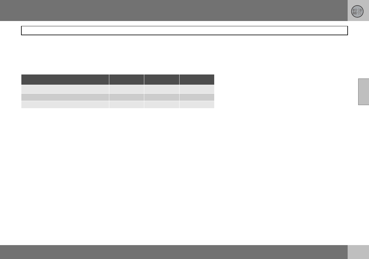
11 Specifications
235
Electrical system
11
General
12 V system with a voltage-regulated alterna-
tor. Single pole system in which the chassis
and engine block are used as conductors.
If the battery is changed, replace it with a
battery of the same cold start capacity and
reserve capacity as the original (see the decal
on the battery).
Certification of the Keyless Drive
system
Siemens VDO Automotive A.G. hereby certi-
fies that this equipment type 5WK4 8952,
5WK48956, 5WK48812 conforms to the es-
sential characteristic requirements and other
relevant regulations of directive 1999/5/EC.
Voltage 12 V 12 V 12 V
Cold start capacity (CCA) 590 A 600 A1700 A2
Reserve capacity (RC) 100 min 120 min 135 min
Capacity (Ah) 60 70 80
1Cars equipped with High Performance audio system.
2Cars equipped with diesel, keyless drive, audio system Premium Sound, fuel-driven heater
or RTI.
11 Specifications
236
Electrical system
11
Bulbs
Lighting Output W Socket
Dipped beam 55 H7
Bi-Xenon 35 D2S
Main beam 55 HB3
Brake lights, reversing lamps, rear fog lamp 21 BA15s
Direction indicators, rear/front (yellow) 21 BAU15s
Rear position/parking lamps, rear side marker lamps 5BAY15d
Courtesy lighting, cargo area lighting, number plate
lighting 5SV8.5
Vanity mirror 1.2 SV5.5
Front position/parking lamps, front side marker lamps 5W2.1x9.5d
Direction indicators in door mirrors (yellow) 5W2.1x9.5d
Fog lamps 55 H11
Glovebox lighting 3BA9
11 Specifications
237
Electrical system
11
Type approval, remote control system
Country
A, B, CY, CZ,
D, DK, E, EST,
F, FIN, GB, GR,
H, I, IRL, L, LT,
LV, M , NL, P,
PL, S, SK, SLO
IS, LI, N, CH
HR
1
1Delphi hereby certifies that this remote control
system conforms to the essential characteristic
requirements and other relevant regulations of
directive 1999/5/EC.
ROK Delphi 2003-07-15,
Germany R-LPD1-03-0151
BR
RC
ETC093LPD0155

Alphabetical index
238
07
A
A/C ..............................................................70
electronic climate control .......................74
manual climate control ...........................71
ABS ...........................................................119
ABS fault ................................................41
Active Yaw Control ...................................121
Additional heater .........................................77
AF – automatic frequency update .............202
Air conditioning ...........................................70
ECC ........................................................72
general ...................................................68
Air distribution .............................................75
ECC ........................................................74
Air quality system, ECC ..............................73
Air vents ......................................................69
Airbag
deactivation ...........................................20
driver’s and front passenger side ..........16
Alarm
alarm lamp ...........................................103
alarm signals ........................................104
arming ..................................................103
automatic alarm activation ...................104
deactivating a triggered alarm .............104
disarming .............................................103
general .................................................103
testing the alarm system ......................105
Alarm, radio functions ...............................200
Approach lighting
active lamps .......................................... 61
setting .................................................... 65
Armrest ....................................................... 86
Audio volume
audio system ....................................... 197
media player ........................................ 197
Audio, see also Sound ............................. 197
AUTO
climate control settings ......................... 72
preset storage ..................................... 199
AUTO CLIMATE .......................................... 72
Auto volume control ................................. 198
Automatic car wash .................................. 162
Automatic dimming .................................... 59
Automatic gearbox ................................... 116
safety systems .................................... 116
towing and recovery ............................ 128
trailer ........................................... 131, 132
W-button ............................................. 118
Automatic locking ..................................... 100
Automatic relocking .................................. 100
Autostart ................................................... 111
Average fuel consumption .......................... 49
B
Backrest
front seat, lowering ................................ 80
rear seat, lowering ................................. 86
Bass speaker ............................................ 197
Battery
care ...................................................... 179
jump starting ........................................ 130
overload ............................................... 109
replacement ......................................... 180
replacing the battery in the
remote control .......................................97
symbols on the battery ........................ 180
Blind spot (BLIS) ....................................... 125
Bonnet ...................................................... 172
Brake fluid, checking and topping up ....... 177
Brake system .................................... 119, 177
Brakes
handbrake .............................................. 56
Bulb holder
location of the bulbs ............................ 184
number plate lighting ........................... 185
removal ................................................ 184
Bulbs
replacement ......................................... 181
specifications ....................................... 236
C
Call
functions during an ongoing call ......... 211
phone volume ...................................... 210
Call waiting ............................................... 209
Calls
making and receiving ........................... 209
Car care

Alphabetical index
239
07
leather upholstery ................................164
Car settings .................................................64
Car upholstery ...........................................163
Car wash ...................................................162
Cargo area
cargo cover ............................................87
lighting ...................................................82
load retaining eyelets .............................90
loading .................................................140
safety net ...............................................90
Cargo cover ................................................87
Catalytic converter ....................................234
recovery ...............................................128
CD discs
storage compartment ............................85
CD functions .............................................203
Checks
fluids and oils ...............................171, 174
Child
child seats and airbags ..........................28
Child seat
fixture system .........................................31
installation ..............................................31
Children
child seats and side airbags ..................21
location in the car, table ........................30
safety equipment ...................................28
Cigarette lighter socket
front seat ................................................45
rear seat .................................................56
Clean inside and out ..................................... 8
Cleaning
automatic car wash ............................. 162
car wash .............................................. 162
seatbelts .............................................. 164
upholstery ............................................ 163
Climate
personal preferences ............................. 64
Climate control
general ................................................... 68
Climate control settings
AUTO ..................................................... 72
Clock .......................................................... 39
setting the clock .................................... 39
Clutch fluid, checking and topping up ..... 177
Coat hanger ................................................ 85
Collision
collision sensors .................................... 23
crash mode ........................................... 27
IC ........................................................... 23
inflatable curtain .................................... 23
Colour code, paint .................................... 165
Combined instrument panel ....................... 39
Compass .................................................... 59
calibration .............................................. 59
Condensation ........................................... 173
Coolant, checking and topping up ........... 176
Cooling system ......................................... 108
Crash, see Collision .................................... 23
Cruise control ............................................. 52
D
Deadlocks ................................................. 102
temporary deactivation ........................ 102
temporary disconnection of alarm
detectors .............................................. 104
Defroster ..................................................... 71
door mirrors ........................................... 71
rear window ........................................... 71
Designation of dimensions ....................... 144
Diesel ........................................................ 173
engine preheater .................................... 41
Diesel filter ................................................ 173
Diesel particle filter ................................... 111
Dipped beam ........................................ 46, 48
Direction indicators .....................................48
Disc text .................................................... 204
Display
messages ...............................................43
Display lighting ........................................... 47
Dolby Surround Pro Logic II .............196, 198
Door mirrors ................................................ 61
Driver’s door control panel
operating ................................................ 57
overview .................................................38
Driving
adverse driving conditions ................... 170
cooling system ..................................... 108

Alphabetical index
240
07
economical ...........................................108
slippery driving conditions ...................108
with open tailgate .................................108
with trailer ............................................131
Driving in water .........................................108
DSTC, see also Stability control system ...121
DSTC, see also Stability system
deactivating/activating .........................121
symbol ...................................................41
E
Easy entry ...................................................80
ECC, electronic climate control ..................69
ECO pressure
fuel economy .......................................148
table .....................................................149
Economical driving ....................................108
Electrical socket
centre console .......................................45
rear seat .................................................56
Electronic immobiliser .................................94
Emergency calls ........................................207
Emergency puncture repair .......................153
Emission control ...........................................7
Emissions ..................................................232
carbon dioxide .....................................233
Emissions system
fault indicator .........................................41
Engine .......................................................172
Engine compartment ................................ 172
Engine oil .................................................. 174
capacities ............................ 227, 228, 229
changing .............................................. 174
driving under adverse driving
conditions ............................................ 226
filter ...................................................... 174
oil grade ............................................... 226
oil pressure ............................................ 42
Engine specifications ............................... 224
Entry, keyless ............................................. 65
Environmental philosophy ............................ 7
EON – Enhanced Other Networks ............ 202
Equalizer ................................................... 198
Expectant mothers
safety ..................................................... 13
F
Fan .............................................................. 70
ECC ....................................................... 72
Fast-wind .................................................. 204
First aid ....................................................... 85
Floor hatch ................................................. 89
Floor mats ............................................ 81, 85
Fluids and oils
checks ......................................... 171, 174
Fluids, capacities ...................................... 230
Fog lamps
on/off ............................................... 47, 49
Frequency update, automatic ................... 202
Front seats
easy entry ..............................................80
lowering ................................................. 80
seating position .....................................80
Fuel
consumption ....................................7, 232
fuel consumption, display ...................... 49
fuel economy ....................................... 148
fuel filter ............................................... 173
fuel system ........................................... 173
level indicator .........................................41
parking heater ........................................ 77
refuelling .............................................. 110
Fuel gauge .................................................. 39
Fuse table
fuses in the engine compartment ........ 189
fuses in the passenger
compartment ....................................... 192
Fuses
general ................................................. 187
relay/fuse box in the engine
compartment ....................................... 188
relay/fuse box in the passenger
compartment ....................................... 191
replacement ......................................... 187
G
Gearbox
automatic ............................................. 116
manual ................................................. 114

Alphabetical index
241
07
Glovebox .....................................................85
locking ..................................................101
Gross vehicle weight .................................222
H
Handbrake ..................................................56
Hazard warning flashers .............................55
Headlamp pattern .....................................141
Headlamps
headlamp washers .................................50
off/on ......................................................46
Heating
front seats ........................................71, 74
Home safe lighting ................................48, 61
Homesafe light duration
setting ....................................................65
I
IDIS ...........................................................207
Ignition keys ..............................................112
IMEI number ..............................................212
Immobiliser ..........................................94, 112
"Important" texts ...........................................6
Incoming calls ...........................................209
Information display ......................................43
Infotainment
menus ..................................................196
Instrument lighting ................................46, 47
Instrument overview
left-hand drive ............................... 34, 206
right-hand drive ..................................... 36
Interior rearview mirror ............................... 59
Intermittent wiping ...................................... 50
ISOFIX
fixture system ........................................ 31
J
Jump starting ........................................... 130
K
Kerb weight .............................................. 222
Key ............................................................. 94
keyless lock and ignition system ........... 98
remote control ....................................... 94
Key blade ................................................... 95
active locks ........................................... 96
Keyless drive .............................................. 98
starting the car .................................... 113
Keyless entry .............................................. 65
Kick-down
automatic gearbox .............................. 116
L
Lambda-sond ........................................... 234
Leather upholstery, washing
instructions ............................................... 164
Lighting
automatic lighting, dipped beam .......... 46
automatic lighting, passenger
compartment ......................................... 83
bulb replacement, general ................... 181
bulbs, specifications ............................ 236
cargo area .............................................. 82
dipped beam .......................................... 46
display lighting ....................................... 47
exterior ................................................... 46
front fog lamps ................................47, 49
headlamp levelling ................................. 46
home safe lighting ...........................48, 61
in passenger compartment .................... 82
instrument lighting .................................47
lighting panel .........................................46
main/dipped beam ................................. 48
position/parking lamps .......................... 46
reading lamps ........................................ 82
rear fog lamp ......................................... 47
Lighting, bulb replacement
cargo area ............................................ 186
courtesy lighting .................................. 185
dipped beam ........................................ 182
direction indicators .............................. 183
fog lamp ............................................... 184
front ..................................................... 181
location of the bulbs in the bulb
holder ................................................... 184
main beam ........................................... 182
parking lamps ...................................... 183
position lamps ..................................... 183
rear lamp .............................................. 184
reflector ................................................ 185

Alphabetical index
242
07
side marker lamps ...............................183
vanity mirror .........................................186
Lights
main beam "flash" ..................................48
Loading
cargo area ..............................................90
general .................................................140
load capacity ........................................140
Lock settings, personal ...............................63
Locking .....................................................100
from inside ...........................................101
from outside .........................................100
unlocking ..............................................100
Lubricants, capacities ...............................230
M
Main beam ..................................................48
off/on ......................................................46
switching and flashing ...........................48
Maintenance
rustproofing ..........................................166
self-maintenance .................................171
Making calls ..............................................209
Manual gearbox ........................................114
Menu structure
media player ........................................205
phone, menu options ...........................214
phone, overview ...................................213
Menus
audio system ........................................196
Messages in the information display .......... 43
Mirrors
door ....................................................... 61
Misting
attending to the windows ...................... 68
rear window ........................................... 71
removing with defroster function .... 71, 73
timer function ........................................ 73
timer function, A/C ................................ 71
N
NEWS ....................................................... 201
News broadcast ....................................... 201
"Note" texts .................................................. 6
O
Oil, see also Engine oil
oil pressure ............................................ 42
Outside temperature gauge ....................... 39
Oxyhydrogen gas ..................................... 130
P
PACOS ....................................................... 19
Paint
paintwork damage and touching up ... 165
Paintwork
colour code ......................................... 165
Parking assistance ................................... 123
sensors for parking assistance ........... 124
Parking brake ....................................... 42, 56
Parking heater
battery and fuel ...................................... 77
general ...................................................76
parking on a hill ..................................... 76
time setting ............................................ 77
Parking lamps .............................................46
Passenger compartment
lighting ...................................................82
Passenger compartment filter ....................68
Personal preferences .................................. 64
approach lighting ...................................65
auto blower adjust .................................64
automatic locking .................................. 65
doors unlock .......................................... 65
homesafe light duration ......................... 65
keyless entry ..........................................65
lock confirm. light ..................................64
recirculation timer .................................. 64
unlock confirm. light .............................. 64
Petrol grade .............................................. 233
Phone ........................................................ 208
calling from the phone book ................ 211
On/Off .................................................. 209
standby mode ...................................... 209
text input .............................................. 210
Phone book
handling numbers ................................ 210
Phone system ........................................... 206
PI seek ...................................................... 202
Pinch protection, sunroof ........................... 63

Alphabetical index
243
07
Polishing ....................................................163
Position lamps ............................................46
Power seat ..................................................81
Power steering fluid, checking and
topping up .................................................177
Power windows ...........................................57
passenger seat ......................................58
Programme functions ................................200
PTY – Programme type .............................201
Putting calls on hold .................................209
R
Radio
radio settings .......................................199
radio stations .......................................199
Radio text ..................................................202
Rain sensor .................................................51
Random, CD and audio files .....................204
RDS functions ...........................................200
resetting ...............................................202
Reading lamps ............................................82
Rearview mirrors
compass ................................................59
electrically retractable ............................61
interior ....................................................59
Recirculation ...............................................70
ECC ........................................................73
Recovery ...................................................128
Refrigerant ..................................................68
Refuelling
fuel cap ................................................ 110
refuelling .............................................. 110
Refuse calls .............................................. 209
REG – Regional radio programmes .......... 202
Relay/fuse box
in the engine compartment ................. 188
in the passenger compartment ........... 191
Remote control ........................................... 94
detachable key blade ............................ 95
functions ................................................ 94
keyless drive .......................................... 98
replacing the battery ............................. 97
Remote control system, type approval .... 237
Reverse gear inhibitor
five-speed ............................................ 114
six-speed, petrol ................................. 115
Rustproofing ............................................. 166
S
Safety ......................................................... 12
safety systems, table ............................. 26
Safety net ................................................... 90
SCAN
CD and audio files ............................... 204
radio stations ....................................... 200
Seat
key memory ........................................... 82
power seat ............................................. 81
Seatbelt ...................................................... 12
pregnancy .............................................. 13
rear seat .................................................13
seatbelt tensioner .................................. 14
Seatbelt reminder .......................................13
Seatbelt tensioner .......................................14
Seats
lowering the front backrest .................... 80
manual setting ....................................... 80
Service programme .................................. 170
Settings, see Personal preferences ............ 64
Side airbags ................................................ 21
SIM card ................................................... 207
SIPS bags ................................................... 21
SMS
read ...................................................... 212
write ..................................................... 212
Soot filter ............................................43, 111
SOOT FILTER FULL .................................. 111
Sound
audio settings ...................................... 197
audio source ........................................ 197
Spare wheel .............................................. 150
floor hatch ..............................................89
Speed dial ................................................. 211
Speed dial numbers .................................. 211
Speed ratings, tyres .................................. 144
Speedometer .............................................. 39
Spin Control .............................................. 121
Spin control .............................................. 121

Alphabetical index
244
07
SRS system
general ...................................................17
switch .....................................................20
Stability control system .............................121
Stability system
indication ...............................................41
Stains ........................................................163
Standby mode, phone ..............................209
Standby, phone .........................................209
Starting from cold
automatic gearbox ...............................116
Starting the engine ....................................111
keyless drive ........................................113
STC ...........................................................121
Steering lock .............................................112
Steering wheel
cruise control .........................................52
keypad .................................................208
keypad left-hand side ............................52
keypad right-hand side ..........................54
steering wheel adjustment .....................55
Stone chips and scratches .......................165
Storage compartment .................................84
CD discs ................................................85
rear side panels ......................................85
Storage spaces in the passenger
compartment ...............................................84
Storing stations, manual and automatic ...199
Subwoofer ................................................ 197
Sunroof ....................................................... 62
closing with remote control ................... 63
pinch protection .................................... 63
sunscreen .............................................. 63
Sunscreen, sunroof .................................... 63
Surround ........................................... 196, 198
Symbols .................................................... 122
indicator symbols .................................. 41
warning symbols ................................... 40
T
Tachometer ................................................ 39
Tailgate
driving with open tailgate .................... 108
locking/unlocking .......................... 94, 100
Tank volume ............................................. 232
Temperature
actual temperature ................................ 69
passenger compartment,
electronic climate control ...................... 74
passenger compartment,
manual climate control .......................... 71
Temporary spare
Temporary spare ................................. 146
Ticket clip ................................................... 85
Timer
A/C ........................................................ 71
ECC ....................................................... 73
Towbar, see Towing equipment ............... 133
Towing ...................................................... 128
Towing equipment
general ................................................. 133
installation ............................................ 135
removing .............................................. 138
specifications ....................................... 134
Towing eye ................................................ 128
TP – traffic information ............................. 200
Traction control ......................................... 121
Traction control system ............................ 121
Traffic information ..................................... 200
Trailer
cable .................................................... 133
driving with a trailer ............................. 131
trailer weight ........................................ 222
Trip computer ............................................. 49
Trip odometer .............................................39
Tuning ....................................................... 199
Type approval, remote control system ..... 237
Type designation ...................................... 220
Tyre
pressure ............................................... 148
Tyres
designation of dimensions ................... 144
direction of rotation ............................. 147
driving characteristics .......................... 144
ECO pressure ...................................... 149

Alphabetical index
245
07
general .................................................144
puncture repair .....................................153
speed ratings .......................................144
summer and winter wheels ..................147
tread wear indicators ...........................145
winter tyres ..........................................145
U
Unlocking
from inside ...........................................101
from outside .........................................100
keyless .................................................100
settings ..................................................64
tailgate .................................................100
V
Vehicle data ..............................................170
Ventilation ...................................................69
Volume
auto volume control .............................198
phone/media player .............................210
programme types .................................202
Volume, see also Audio volume ................197
W
Warning lamp
Stability and traction control system ...121
Warning symbol, AIRBAG system ..............15
"Warning" texts .............................................6
Warning triangle ........................................150
Washer
rear window ........................................... 51
Washer fluid, topping up .......................... 176
Washers
windscreen and headlamps .................. 50
Washing the car ........................................ 162
Waxing ...................................................... 163
Wheels
fitting ................................................... 152
removal ................................................ 151
rims ...................................................... 146
Whiplash injury WHIPS ............................... 24
WHIPS ........................................................ 24
child seat/booster cushion .................... 24
Windscreen wipers
rain sensor ............................................. 51
Windscreen wipers and washer ................. 50
Winter tyres .............................................. 145
Wiper
rear window ........................................... 51
Wiper blades
replacing, rear window ........................ 178
replacing, windscreen ......................... 178

Volvo Car Corporation TP 8788 (EE English), AT 0637, Printed in Sweden, Göteborg 2006, Copyright © 2000-2006 Volvo Car Corporation
Volvo. for life
