Volvo Vhd Users Manual PV776 TSP20139484
VHD to the manual 2f91478a-6ddf-47cf-ac50-36da3a9bd124
2015-01-26
: Volvo Volvo-Vhd-Users-Manual-233593 volvo-vhd-users-manual-233593 volvo pdf
Open the PDF directly: View PDF ![]() .
.
Page Count: 300 [warning: Documents this large are best viewed by clicking the View PDF Link!]

New Roads.TM
OPERATOR’S MANUAL
VHD
Foreword
This manual contains information concerning the safe operation of your
vehicle. It is extremely important that this information is read and un-
derstood before the vehicle is operated. This manual also contains a
considerable amount of information concerning the vehicle, such as ve-
hicle identification, Preventive Maintenance recommendations and a log
for your service records. Please keep this in the vehicle at all times. In-
formation from other component manufacturers is supplied in separate
manuals in the Owner’s Package.
NOTE! It is important that this manual stays with the vehicle when it
is sold. Important safety information must be passed on to the new cus-
tomer. The service information contained in this manual gives the
owner important information about maintaining the vehicle but is not
intended as a substitute for the Preventive Maintenance Service Manual
and must not be regarded as such.
The National Highway Traffic Safety Administration (NHTSA) and
Volvo Trucks North America, Inc. should be informed immediately
if you believe that the vehicle has a defect that could cause a crash,
injury or death.
Contact NHTSA by calling the Auto Safety Hotline at 1 (800) 424–
9393 (or 366–0123 in the Washington, DC area) or by writing to:
NHTSA, U.S. Department of Transportation, Washington, DC 20590.
Volvo Trucks North America, Inc.
Greensboro, NC USA
Order number: PV776-20 139484
© 2000 Volvo Trucks North America, Inc., Greensboro, NC USA
All rights reserved. No part of this publication may be reproduced,
stored in retrieval system, or transmitted in any forms by any means,
electronic, mechanical, photocopying, recording or otherwise, without
the prior written permission of Volvo Trucks North America, Inc..

Contents
General Information ............................. 1
Information For the Owner ................... 1
General Safety Information .................. 3
Modifications to Vehicle ....................... 7
Exhaust and Noise Emissions ............... 8
Vehicle Data ........................................ 16
Vehicle Access ...................................... 19
Cab Doors and Door Lock ................. 19
Cab Entry and Exit ............................. 21
Hood .................................................... 26
Pre-Trip Inspection and Daily Mainte-
nance ..................................................... 28
General ................................................ 28
Pre-Trip Inspection Quick List ........... 29
Daily Maintenance .............................. 41
Additional Safety Features ................. 46
Safety Belts ......................................... 46
SRS Airbag ......................................... 55
Safety Equipment ................................ 62
VORAD Collision Warning System ... 63
Instruments and Controls ................... 64
Dash Overview .................................... 64
Instrument Cluster Overview .............. 65
Telltale Overview ................................ 66
Graphic Display Telltale Overview .... 67
Left Instrument Section ...................... 68
Main Instrument Section ..................... 76
Right Instrument Section .................... 83
Changing Telltale Bulbs In Cluster .... 89
Steering Column Switches .................. 91
Left Switch Cluster ............................. 94
Driving Light Switches ....................... 98
Right Switch Cluster ......................... 100
Pneumatic Switch Cluster ................. 104
Optional Switch Cluster .................... 106
Miscellaneous Switches .................... 107
Graphic Display ................................. 108
Graphic Display Overview ............... 108
Graphic Display Controls ................. 109
Graphic Display Telltales .................. 111
Information and Stop Messages ....... 112
Information Telltale ........................... 113
Stop Telltale ...................................... 120
Acknowledge Information and Stop
Messages ........................................... 124
Main Menu: Set-Up Mode ............... 126
Main Menu: System Diagnostic ....... 131
Main Menu: Data Log Mode (Volvo
Engine Only) ..................................... 146
Main Menu: Password Input ............ 152
Main Menu: Gauge ........................... 153
Main Menu: Fuel Economy (option) 157
Main Menu: Time/Distance .............. 159
Main Menu: FAULTS? ..................... 164
Heating and Air Conditioning ......... 168
General .............................................. 168
Climate Unit Main Control Panel .... 169
Cab Ventilation .................................. 177
Cab Air Filter .................................... 178
A/C Diagnostic Module .................... 179
Seats ..................................................... 180
General .............................................. 180
National Standard Seat Adjustments 181
Volvo Standard Seat Adjustments .... 182
National Stationary Seat ................... 183
Cab Interior ....................................... 184
Interior/Reading Lights ..................... 184
Communication and Entertainment 187
Antennas ............................................ 187

Stereo/Radio ...................................... 188
Communication Equipment .............. 189
Fuel Economy Driving ...................... 190
Fuel Economy ................................... 190
Engine Start and Operation ............. 197
Starting the Engine ........................... 197
Cold Weather Start and Operation ... 202
Engine Operation .............................. 209
Cruise Control ................................... 218
Fuel Tank(s) ...................................... 220
Clutch and Transmission .................. 222
Clutch ................................................ 222
Brakes ................................................. 223
Brakes ................................................ 223
Electrical System ............................... 244
Electrical System ............................... 244
Power Steering ................................... 256
General .............................................. 256
Axles and Wheels ............................... 258
Axles .................................................. 258
Wheels ............................................... 261
Fifth Wheel Instructions ................... 264
Fifth Wheel General Information ..... 264
Fifth Wheel ....................................... 265
Fifth Wheel Slider (option) .............. 267
Unlocking the Fifth Wheel ............... 268
Trailer Coupling Procedures ............. 270
Trailer Uncoupling Procedures ......... 275
Operating the Fifth Wheel Slider ..... 280
Emergency Information .................... 282
Towing Procedure ............................. 282
Service Information ........................... 287
Service Assistance and Manuals ...... 287
Index .................................................... 289
Warning Label Information
IMPORTANT
Before driving this vehicle, be certain that you have read and that
you fully understand each and every step of the driving and han-
dling information in this Operator’s Manual. Be certain that you
fully understand and follow all safety warnings. It is extremely im-
portant that this information is read and understood before the
vehicle is operated.
IT IS IMPORTANT THAT THE FOLLOW-
ING INFORMATION CONCERNING
LABELS BE READ, UNDERSTOOD
AND ALWAYS FOLLOWED.
The following types of labels are used
throughout this manual:
NOTE! A note defines an operating proce-
dure, practice, condition, etc., which is
essential to proper operation of the vehicle.
CAUTION
A caution label directs the operator’s
attention to unsafe practices where per-
sonal injury is not likely but property
damage could occur. The caution label is
in black type on a white background
with a black border.
WARNING
A warning label directs the operator’s
attention to unsafe practices which could
result in personal injury or severe dam-
age to the vehicle. The warning label is
in black type on a gray background
with a black border.
A danger label directs the operator’s at-
tention to unsafe practices which could
result in serious personal injury or death.
The caution label is in white type on a
black background with a black border.


General Information 1
Information For the Owner
If there are questions on the maintenance
and performance of your vehicle, please
discuss them with your Volvo Truck dealer.
Your authorized dealer is required to have
trained mechanics, special tools and spare
parts to fully service your vehicle. If
necessary, your dealer will contact the man-
ufacturer for any assistance.
In addition to this Operator’s Manual, there
may be additional instruction/operator’s
manuals supplied by component manufac-
turers. These manuals are placed in the
Owner’s Package and placed in the cab. Be
sure to read all the manuals thoroughly be-
fore operating the vehicle.
Also, various safety labels may be placed
on components by the component manufac-
turer. Be sure to read and follow these
labels to prevent damage to the vehicle,
personal injury or even death.
Information in this manual refers to Volvo
components and Volvo drivetrain. Informa-
tion concerning non-Volvo engines and/or
drivetrains can be obtained by contacting
the respective manufacturer.
Establish a Preventive Maintenance Pro-
gram with the help of your local Volvo
Truck dealer. A Preventive Maintenance
Program makes it possible to maximize the
amount of time your vehicle is up and run-
ning, resulting in longer component life.
This makes for a safer vehicle by reducing
any mechanical failures due to poor mainte-
nance practices.
Various truck warranty coverage plans, con-
tingent on application and weight class, are
available. Please contact an authorized
Volvo Truck Dealer for complete details.
Replacement warranty certificates for Volvo
Trucks are available from Volvo dealers.
For trucks placed in service after August 1,
2000 and operating in the USA and
Canada, Volvo dealers can print copies of
the Standard Truck Warranty Certificate
and the Premium (Purchased) Truck Cover-
age Certificate. Copies are available in
either English or Canadian French at the
dealer communication system (DCS) web-
site. Look in the Service/Warranty folder.
NOTE! Federal law requires manufacturers
to notify owners of its products in the event
of a non-compliance to a Federal Motor
Vehicle Safety Standard or if a safety re-
lated defect is discovered. If you are not
the original owner of this vehicle, please
notify us about the change in ownership at
the address below or through an authorized
Volvo Truck dealer. This is the only way
we will be able to contact you if necessary.
Volvo Trucks North America, Inc.
Att: Vehicle Registration dept.
P. O. Box 26115
Greensboro, NC 27402–6115
United States of America
2 General Information
Do Not Remove this manual from the ve-
hicle. It contains important operational and
safety information that is needed by all
drivers and owners of this vehicle.
This Operator’s Manual covers Volvo
VHD-series vehicles manufactured by
Volvo Trucks North America, Inc. with any
of the following designations:
VHD42 VHD64 VHD84 VHD104
VHD124 VHD42T VHD64T VHD84T
T=tractor, F=forward position axle
B=back position axle
Explanation: The first number after the
model designation (4, 6, 8, 10 or 12) repre-
sents the total number of wheels (hubs) per
vehicle. The last number (2 or 4) represents
the number of wheels (hubs) that drive the
vehicle.
This manual, together with manuals for
specific components, for example, Volvo
engine, Cummins engine, Eaton transmis-
sion, etc., contain important information for
you to be able to operate this vehicle
safely. They contain advice and instructions
which will enable you to get the operating
economy and performance that you expect
from this quality vehicle.
All information, illustrations and specifica-
tions contained in this manual are based
upon the latest product information avail-
able at the time of publication. If any
questions arise concerning the current sta-
tus of Federal or state laws, the appropriate
Federal or state agency should be contacted.
Volvo Trucks North America, Inc. reserves
the right to make changes at any time or to
change specifications or design without no-
tice and without incurring obligation.
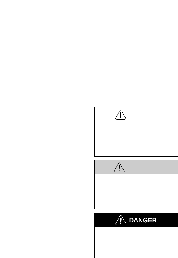
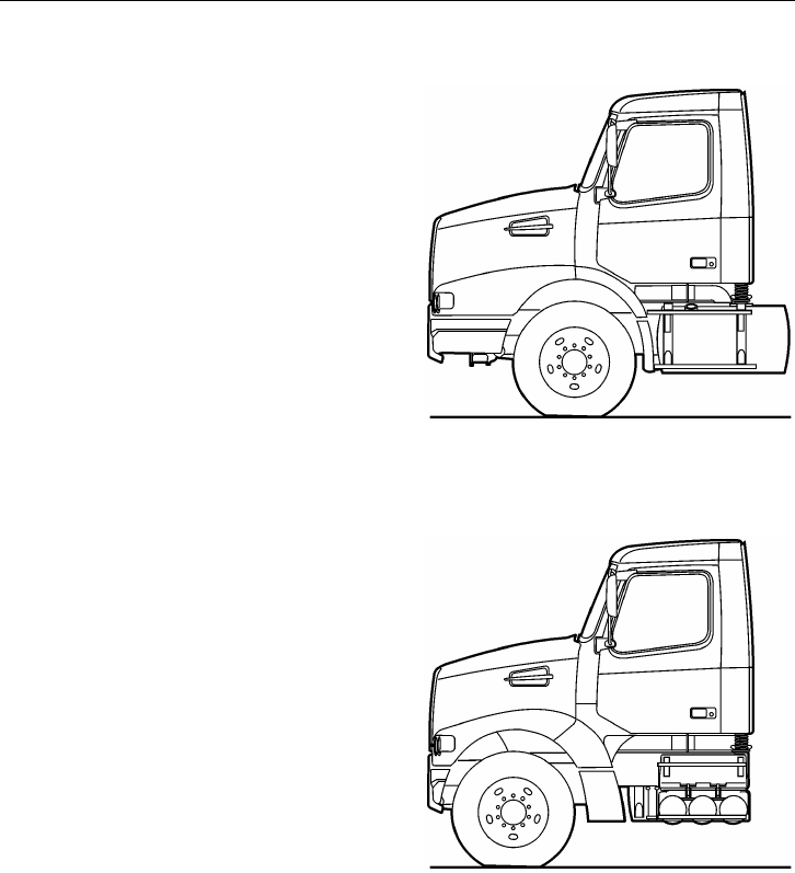
W8002807
Back position axle
W0001920
Forward position axle
General Information 3
General Safety Information
Operating the Vehicle
Every vehicle, including heavy duty vehi-
cles, has blind spots. The size of blind
spots varies from driver to driver and from
situation to situation. As a skilled, profes-
sional driver, you are in the best position to
avoid accidents in turns, lane changes or
other maneuvers. Volvo Trucks North
America, Inc. provides standard equipment
(such as cabs, windshields, window sizes
and mirrors), preferred by most owners and
drivers under most conditions and in most
applications.
However, due to differences in the size of
drivers, their seating positions, the way that
they use and operate their vehicles, per-
sonal preferences and other factors, no
combination of mirrors and other visibility
enhancement devices will eliminate all
blind spots in every situation.
The safe operation of this vehicle is up to
you. Because of your special preferences,
needs and circumstances, you may want to
add extra mirrors and/or other visibility en-
hancement devices. If so, you should
contact an authorized Volvo Truck dealer to
obtain those parts which best fit your own
personal needs and preferences.
WARNING
All items within the cab must be secured
before the vehicle is set in motion. This
includes, but is not limited to, drinks,
clothes, books, televisions, etc. In the
event of a collision, loose items could
fly around inside the cab. This could
cause personal injury.
Never try to operate or work on this
vehicle while under the influence of al-
cohol. Your reflexes can be affected by
even a small amount of alcohol. Drink-
ing and operating this vehicle can lead
to an accident, causing serious personal
injury or death.
4 General Information
Operating In Bobtail Mode
Tractors are equipped with a bobtail air
brake proportioning valve which automati-
cally redistributes the braking force between
front and rear axles when not hooked up to
a semitrailer (bobtail operation).
When operating in bobtail mode, the rear
brake chambers receive reduced or propor-
tional brake air pressure. When the tractor
is towing a trailer, the rear brake chambers
will receive full (normal) brake pressure.
NOTE! When operating bobtail, be certain
that glad hands, trailer air hoses, electrical
cable and connectors are properly stowed
and secure. Do not allow them to rub or
chafe on other components.
WARNING
When operating bobtail, the brake
system on the vehicle reduces the possi-
bility of rear wheel brake lockup, except
on full pedal application. When bobtail-
ing, be certain that adequate pedal
pressure is applied. There is no need to
reduce pedal effort. Failure to do so may
result in increased stopping distances.
General Information 5
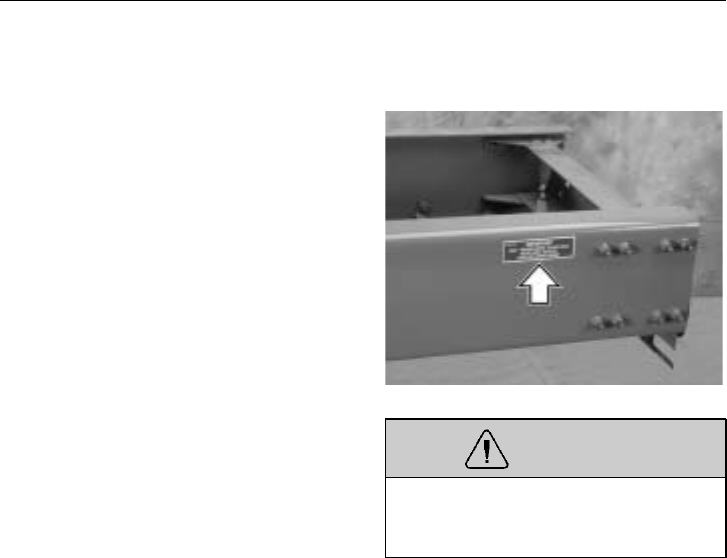
Do Not Overload
This vehicle has been designed and assem-
bled for a maximum gross vehicle weight
rating (GVWR) and a maximum front and
rear axle weights rating (FAWR and
RAWR). The actual rating for this vehicle
can be found on the label attached to the
door frame on the driver’s side. If any of
these three ratings is exceeded and over-
loading occurs, instability, poor handling,
failure of parts and accelerated wear can
occur.
Under no circumstances should the pub-
lished GVWR, FAWR, and/or RAWR be
exceeded. Failure to observe these pre-
cautions can lead to the loss of vehicle
control, resulting in a crash causing seri-
ous personal injury or death.
Do not exceed the load rating of the
tires or the vehicle weight ratings. Over-
loading may result in tire failure causing
loss of vehicle control, leading to an ac-
cident resulting in severe personal injury
or death.
W0001210
Operating
Before driving this vehicle, locate the in-
struments and controls, and become
thoroughly familiar with their operation.
After starting and when driving, always
check to make sure that the instrument
readings are normal.

6 General Information
Reporting Safety Defects
USA
The National Highway Traffic Safety Ad-
ministration (NHTSA) and Volvo Trucks
North America, Inc. should be informed
immediately if you believe that the vehicle
has a defect that could cause a crash, injury
or death.
Contact NHTSA by calling the Auto Safety
Hotline at 1 (800) 424–9393 (or 366–0123
in the Washington, DC area) or by writing
to: NHTSA, U. S. Department of Trans-
portation, Washington, DC 20590.
1 (800) 424-9393
Canada
Refer consumer complaints to Volvo Trucks
Canada, Inc. or to the Transport Canada -
Department of Public Complaints, Recalls
and Investigations. 1 (905) 795-1555
Mexico
Volvo Trucks of Mexico, S.A. de C.V.
should be informed immediately if you be-
lieve the vehicle has a defect that could
cause a crash, injury or death. Contact
Volvo Trucks de Mexico by calling or by
writing to: Volvo Trucks de Mexico, S.A.
de C.V., Prol. Paseo de la Reforma 600,
1er. Piso — 121, Col. Santa Fe Peña
Blanca, C.P. 01210, México, D.F.
01 (800) 90 94 900
NOTE! For a listing of other contacts for
information or help, see page 287.
General Information 7
Modifications to Vehicle
Chassis Frame
Frame side rails are heat treated. No weld-
ing is permitted because structural failure
may result. Do not drill through either top
or bottom flanges. A warning label is also
attached to the frame for information.
Drilling is permitted in the frame web in
accordance with a specified hole spacing
pattern. Consult a Volvo Truck dealer to
obtain approved hole spacing dimensions or
refer to the Frame Rail and Cross Member
Service Manual.
Frame rail and cross member nuts and bolts
should be checked periodically and tight-
ened to the specified torque if necessary.
W7001174
WARNING
Do not weld on any part of the frame or
drill holes in the top or bottom flanges.
Serious structural damage could occur.
Frame Alterations
Under no circumstances can the frame be
cut and an extension piece added to in-
crease the wheelbase. The only alteration
allowed is wheel base shortening, where
the only change in the frame rail is a new
hole pattern drilled for the new location of
the rear suspension.
Welding In Vehicle
Do not weld anywhere in or on the vehicle
before disconnecting batteries, all electronic
control units (ECU) and instrument cluster.
See page 249 for more information. Do not
use oxy/acetylene welding to repair cab
panels. Refer to the service manuals for
specific information.

8 General Information
Exhaust and Noise Emissions
General
USA
The Federal Clean Air Act, Section 203 (a)
(3), states the following concerning the re-
moval of air pollution control devices or
modification of a certified engine to a non-
certified configuration:
“The following acts and the causing thereof
are prohibited:
(3) For any person to remove or render in-
operative any device or element of design
installed on or in a motor vehicle or motor
vehicle engine in compliance with regula-
tions under this part prior to its sale and
delivery to the ultimate purchaser, or for
any manufacturer or dealer knowingly to
remove or render inoperative any such de-
sign after sale and delivery to the ultimate
purchaser.”
Specifically, please note that no person may
make such changes prior to the sale and
delivery of the vehicle to the ultimate pur-
chaser, and, in addition, no manufacturer or
dealer may take such action after sale and
delivery of the vehicle to the ultimate pur-
chaser. The law provides a penalty of up to
$10, 000 for each violation.
Canada
The same conditions that apply in the USA
apply to Canada, with one exception. After
the vehicle is sold to a retail customer, that
is, the end user, the jurisdiction controlling
the emission control devices becomes the
province in which the vehicle is licensed.
No changes should be made that render any
or all of the devices inoperative.
Should the owner/operator wish to make
any changes to the emission control de-
vices, check with the provincial authority
before making any such changes.
Mexico
The same conditions that apply in the USA
apply to Mexico. Refer to the Mexican
Federal Law for Emission Control which
adheres to EPA regulations. No changes
should be made that render any or all of
the emissions control devices inoperative.
Should the owner/operator wish to make
any changes to the emission control de-
vices, check with the state authority before
making any such changes.

General Information 9
California Emission Control Warranty Statement
YOUR WARRANTY RIGHTS AND OBLIGATIONS
The California Air Resources Board and Volvo Trucks North America , Inc. (VTNA) are
pleased to explain the emission control system warranty on your vehicle. In California,
new motor vehicles must be designed, built and equipped to meet the State’s stringent
anti-smog standards. Volvo Trucks North America, Inc. must warrant the emission control
system on your vehicle for the periods of time listed listed below provided there has been
no abuse, neglect or improper maintenance of your vehicle.
Your emission control system may include parts such as carburetor or fuel injection system
and engine computer. Also included may be hoses, belts, connectors and other emission-
related assemblies.
Where a warrantable condition exists, Volvo Trucks North America, Inc. will repair your
vehicle at no cost to you including diagnosis, parts and labor.
MANUFACTURER’S WARRANTY COVERAGE
This warranty is applicable for a period of five years, 100 000 miles or 3 000 hours of op-
eration, whichever first occurs. If an emission-related part of your vehicle is defective, the
part will be repaired or replaced by Volvo Trucks North America, Inc.
This is your emission control system DEFECTS WARRANTY.
OWNER’S WARRANTY RESPONSIBILITIES
As the vehicle owner, you are responsible for the performance of the required maintenance
listed in your owner’s manual. Volvo Trucks North America, Inc. recommends that you re-
tain all receipts covering maintenance on your truck but Volvo Trucks North America, Inc.
cannot deny warranty solely for the lack of receipts or for your failure to ensure the per-
formance of all scheduled maintenance.
You are responsible for presenting your vehicle to a Volvo Trucks North America, Inc.
dealer as soon as a problem exists. The warranty repairs should be completed in a reason-
able amount of time, not to exceed 30 days.
As the vehicle owner, you should also be aware that Volvo Trucks North America, Inc.
may deny you warranty coverage if your vehicle or a part has failed due to abuse, neglect,
improper maintenance or unapproved modifications.
If you have any questions regarding your warranty rights and responsibilities, you should
contact Volvo Trucks North America, Inc., Warranty Administration, (336) 393-2000 or
the California Air Resources Board at 9480 Telstar Avenue, El Monte, CA 91731.

10 General Information
EMISSION CONTROL SYSTEM WARRANTY
Volvo Trucks North America, Inc. WARRANTS TO THE ORIGINAL OWNER, AND
EACH SUBSEQUENT OWNER, OF A NEW TRUCK POWERED BY A VOLVO
DIESEL ENGINE THAT THE EMISSION CONTROL SYSTEM OF YOUR TRUCK:
1 Is designed, built and equipped so as to conform at the time of sale to all regulations
of the U.S. Environmental Protection Agency and the California California Air Re-
sources Board applicable at the time of the manufacture; and
2 Is free from defects in material and workmanship which will cause the emission con-
trol components not to function as designed for a period of use of 5 years or 100 000
miles or 3 000 hours of engine operation, whichever comes first.
The 5 years/100 000 miles/3 000 hour warranty period shall begin on the date the vehicle
is first delivered to the first retail purchaser or if the vehicle is placed in service as a
demonstrator company vehicle prior to the sale at retail, on the date the vehicle is the first
placed in service.
The emission control system of your new Volvo engine was designed, built and tested us-
ing genuine Volvo parts, and the engine is certified as being in conformity with Federal
and California emission control regulations. Accordingly, it is recommended that any re-
placement parts used for maintenance, replacement or repair without invalidating this
warranty; the cost of such services or or parts, however, will not be covered under the war-
ranty except in an emergency situation. A part not being available or a repair not being
completed within 30 days also constitutes an emergency.
Use of replacement parts which are not of equivalent quality may impair the effectiveness
of emission control systems. If other than Volvo parts are used for maintenance, owner
should obtain assurances that suck parts are warranted by their manufacturer to be equiva-
lent to genuine Volvo parts. However, the use of other than Volvo replacement parts does
not invalidate the warranty on other components, unless such parts cause damage to war-
ranted parts.
Repairs and service covered by the warranty will be performed by an authorized Volvo
Trucks North America, Inc. dealer at his place of business with no charge for parts or la-
bor (including diagnosis) using Volvo parts for the emission control system, that requires
replacement and is covered by the warranty and found defective. In case of an emergency,
where an authorized Volvo Trucks North America, Inc. dealer is not available, repairs may
be performed at any available service establishment or by the owner, using any equivalent
replacement parts and Volvo Trucks North America, Inc. will reimburse the owner for such
repairs (including diagnosis) not to exceed Volvo Trucks North America, Inc’s suggested
retail retail price for the warranted parts and the labor rate appropriate for the geographical
area and the tasks performed.
Replaced parts and paid invoices must be presented to a Volvo Trucks North America, Inc.
dealer for reimbursement.

General Information 11
The emissions control parts covered by this Emission Control System Warranty are listed
under "What Is Covered by the Emissions Warranty." You are responsible for the perfor-
mance of all required maintenance on your new Volvo engine, including maintenance or
repairs needed due to severe operating conditions. Volvo Trucks North America, Inc. will
not deny a warranty claim solely because you have no record of maintenance. However,
Volvo Trucks North America, Inc. may deny a warranty claim if your failure to perform
required maintenance resulted in the failure of a warranted part. Receipts covering the
performance of regular maintenance should be retained in the event questions arise con-
cerning maintenance. The receipts should be transferred to each subsequent owner of the
vehicle with the emission warranted engine.
CUSTOMER ASSISTANCE
Volvo Trucks North America, Inc. wishes to help to assure that the Emission Control Sys-
tem Warranty is properly administered. In the event that you do not receive the warranty
service to which you believe you are entitled under the Emission Control System Warranty,
you should contact Volvo Trucks North America, Inc. Warranty Administration, (336) 393-
2000. The address and telephone number of each Regional Office is in your vehicle
owner’s manual. If you need additional assistance or information concerning the Emission
Control System Warranty, contact: Volvo Trucks North America, Inc., Warranty Adminis-
tration, (336) 393-2000.
WHAT IS NOT COVERED BY THE EMISSION WARRANTY
This warranty does not cover:
1 Malfunctions in any part caused by any of the following: misuse, abuse, improper
adjustments unless performed by a Volvo Trucks North America, Inc. dealer, modifi-
cations, alterations, tampering, disconnection, improper or inadequate maintenance, or
use of fuels not recommended for the engine as described in the owner’s manual.
2 Damage resulting from accident, acts of nature or other events beyond the control of
Volvo Trucks North America, Inc.
3 The replacement of expendable maintenance items such as filters, hoses, belts, oil,
thermostat and coolant made in connection with scheduled maintenance services once
these parts have been replaced. Any parts replaced under warranty before the first re-
quired replacement point are warranted for the remainder of the warranty period.
4 Replacement items which are not genuine Volvo parts or not authorized by Volvo
Trucks North America, Inc.
5 Loss of time, inconvenience, loss of use of vehicle or engine, or commercial loss.
6 Any vehicle on which the odometer or hourmeter has been disconnected or the
mileage (or hours) has been altered so the actual usage cannot be readily be deter-
mined.
7 Any vehicle registered and normally operated outside the United States.

12 General Information
WHAT IS COVERED BY THE EMISSION WARRANTY
The following is a list of the items that are considered a part of the Emission Control Sys-
tems and are covered by the Emission Warranty when installed as original equipment by
Volvo Trucks North America, Inc. on vehicles which were built to conform to Environ-
mental Protection Agency and California Air Resources Board regulations
IMPORTANT - This may not include expendable maintenance items. Emission related
parts requiring scheduled maintenance are warranted until their first scheduled replacement
point.
I. Fuel Injection System
II. Air Induction System
A. Intake Manifold
B. Turbocharge System
C. Charge Air Cooler (Intercooler)
III. Exhaust Manifold
IV. Miscellaneous Items Used in Above Systems
A. Hose, clamps, fittings and tubing
B. Pulleys, belts and idlers
C. Vacuum, temperature, and time sensitive valves and switches
D. Mounting hardware, sealing gaskets and PVC (if applicable)
THIS CALIFORNIA EMISSION CONTROL WARRANTY STATEMENT IN NO WAY
REPLACES, MODIFIES, ALTERS OR SUPERSEDES THE TRUCK WARRANTY CER-
TIFICATE, ITS TERMS AND CONDITIONS, AND ITS
LIMITATIONS AND EXCLUSIONS.
BE CERTAIN YOU READ AND UNDERSTAND ALL WARRANTIES WHICH
ACCOMPANIED YOUR VEHICLE.
NOTE! Warranty coverage is subject to
change without notice. Contact your Volvo
Truck dealer for the current warranty
statement.

General Information 13
Noise Emissions
Volvo Trucks North America, Inc. warrants
to the first person who purchases this vehi-
cle for purposes other than resale and to
each subsequent purchaser, that this vehicle
as manufactured by Volvo Trucks North
America, Inc. was designed, built and
equipped to conform, at the time it left the
control of Volvo Trucks North America,
Inc., with all applicable U.S. EPA Noise
Control Regulations.
This warranty covers this vehicle as de-
signed, built and equipped by Volvo Trucks
North America, Inc., and is not limited to
any particular part, component or system of
the vehicle manufactured by Volvo Trucks
North America, Inc. Defects in design, as-
sembly or in any part, component or system
of the vehicle as manufactured by Volvo
Trucks North America, Inc., which, at the
time it left the control of Volvo Trucks
North America, Inc. caused noise emissions
to exceed Federal standards, are covered by
this warranty for the life of the vehicle.

14 General Information
Tampering with Noise Control System
Federal law prohibits the following acts or
the causing thereof:
(1) The removal or rendering inoperative by
any person, other than for purposes of
maintenance, repair, or replacement, of any
device or element of design incorporated
into any new vehicle for the purpose of
noise control prior to its sale or delivery to
the ultimate purchaser or while it is in use;
or
(2) the use of the vehicle after such device
or element of design has been removed or
rendered inoperative by any person.
Among those acts presumed to constitute
tampering are the acts listed below:
Air Intake System
Removing or rendering inoperative the air
cleaner or intake piping.
Engine Cooling Fan
Removing or rendering inoperative the fan
clutch.
Removing the fan shroud.
Engine
Removing or altering engine speed pro-
gramming so as to allow engine speed to
exceed manufacturer’s specifications.
Modifying the parameters of the Engine
Electronic Control Unit.

General Information 15
Fuel System
Removing or altering engine speed pro-
gramming so as to allow engine speed to
exceed manufacturer’s specifications.
Inner Fender Shields and Cab Skirts
Removing shields or skirts.
Cutting away parts of shields, skirts or dam-
aged or loose portions of shields or skirts.
16 General Information
Vehicle Data
Identification and Labels
It is extremely important that the correct
vehicle model and serial number are given
whenever replacement parts or service liter-
ature are ordered. Using these numbers, as
well as giving the major component model
and serial numbers, will prevent delay and
errors in obtaining the correct material.
Space is given on the rear inside cover of
this manual for noting the main component
model and serial numbers.
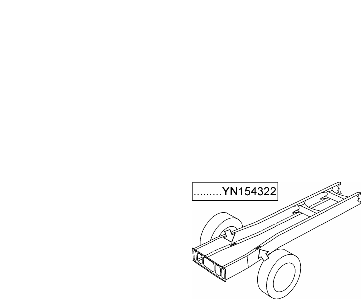
The full 17–digit Vehicle Identification
Number (VIN) is shown on the Vehicle
Identification label located in the door
opening on the driver’s side (see next
page). The 8–digit chassis number is
stamped into the right-hand frame rail un-
derside and the left-hand frame rail topside,
42 inches (1065 mm) back from the front
edge of the frame rail. The use of this num-
ber is very helpful when ordering parts for
your vehicle. W0001732
Vehicle Order
The Vehicle Order is a complete and de-
tailed record of all data pertaining to the
assembly of the vehicle. It should be filed
in the Owner’s office where it will be read-
ily available for reference. Any changes
made to the vehicle must become a part of
the Vehicle Order and must comply with all
applicable Federal Motor Vehicle Safety
Standards.
General Information 17
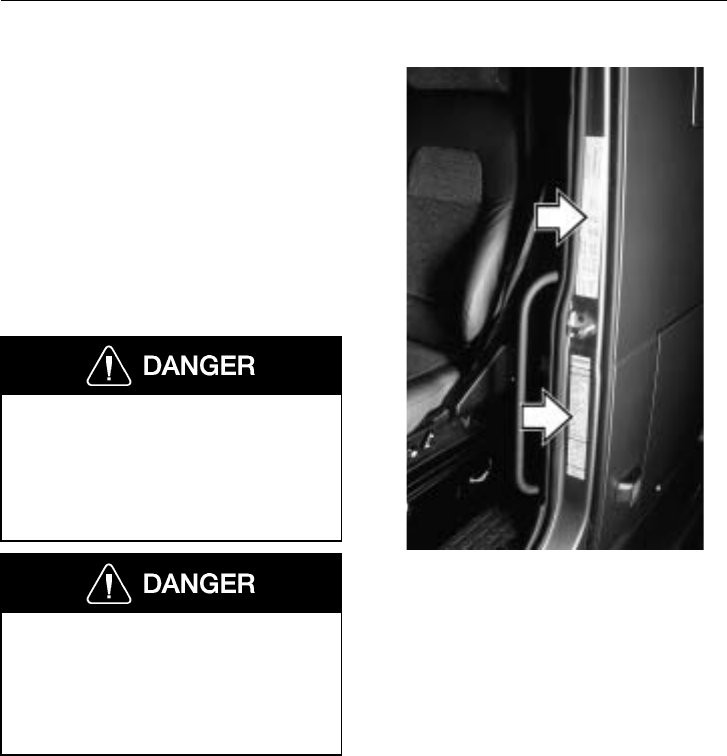
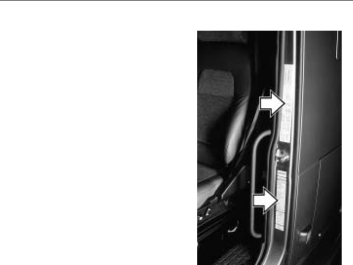
Identification and Certification Labels
There are two labels that are located on the
rear, lower face of the driver side door
frame. These should be part of the vehicle
at all times.
The VIN is shown on the Vehicle Identifi-
cation label. The VIN includes the vehicle
make, model series, weight class, engine
model, where the vehicle was built and the
vehicle serial number. This label also
shows the truck model designation, major
component model and serial number, cab
model and serial number, cab and chassis
paint colors, and color numbers.
On the upper part of the door frame is the
Certification label showing the axle and
load ratings for the vehicle as it was built.
Do not exceed these ratings by overloading.
NOTE! To deter tampering with the origi-
nal build information, the information on
the label will be destroyed if label is
removed. If for any reason a label is dam-
aged, contact your Volvo Truck dealer for a
replacement.
W0001210
Noise Emission Control Label
A Noise Emission Control label is located
in the rear of the door frame. It is the
Owner’s responsibility to maintain the vehi-
cle so that it conforms to EPA regulations.
Refer to page 14 for a listing on what con-
stitutes tampering with the Noise Emissions
Control.
18 General Information
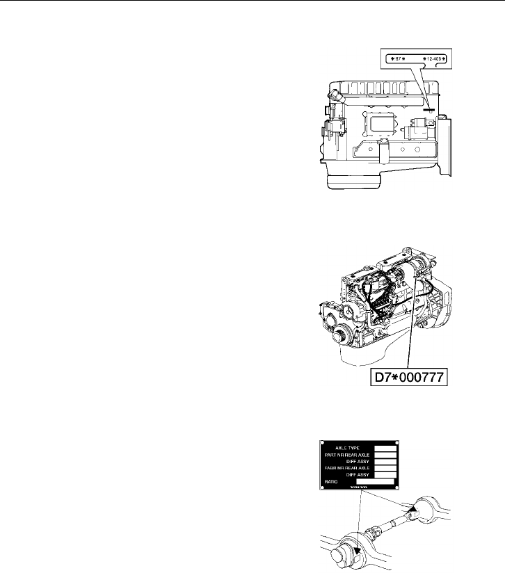
Components
The Volvo D12 engine serial number is lo-
cated on the rear, left side of the cylinder
block.
There is also a label on the engine elec-
tronic control unit that shows the engine
serial number.
W0001529
The Volvo D7 engine serial number is lo-
cated on the rear, left side of the cylinder
block.
There is also a label on the rear valve cover
that shows the engine serial number.
W2002707
The Volvo rear axle model and serial num-
ber is located on the right side of the
transfer gear housing on the tandem front
axle. It is located on the left side of the dif-
ferential housing on the tandem rear axle
and on the right side of the single axle.
W4000894
Vehicle Access 19
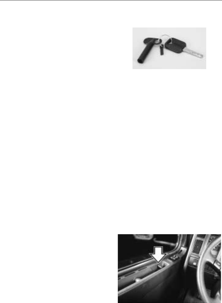
Cab Doors and Door Lock
The cab door is unlocked with the same
key used for the ignition lock. Keys can be
made to fit only one vehicle or all the vehi-
cles in a fleet of Volvos. A tool for
changing bulbs in the instrument cluster is
included on the keychain.
The key fits in the door lock either way.
Insert the key and turn it 1/4 turn counter-
clockwise to unlock or clockwise to lock
the door.
NOTE! The vehicle is delivered with 2
identical keys. If more keys are needed,
order them through your Volvo Truck au-
thorized dealer. The keys are laser cut and
require a special machine for copying,
available through the dealer. Record the key
code and keep it in a secure place. A new
key can be made if the keys are lost.
The door locks are mechanically or electri-
cally operated. The lock is activated by
either the key from the outside or the door
lock handle from the inside. With mechani-
cal locks, only one door can be
locked/unlocked at a time. With electrical
locks, both doors will be locked/unlocked
by operating either the key or the inner
door lock handle on either side.
W0001231
Key code on tag of keychain
To lock either door from the inside, push
the door lock handle forward. The handle
will stay in place, indicating the door is
locked. It can be unlocked without opening
the door by moving the door lock handle to
the middle position.
No door can be locked while it is still
open. The door must be closed for the lock
to work. In the event of a power failure the
electrical lock system reverts back to a me-
chanically functioning system. W8001462
20 Vehicle Access
The door has a position lock that enables
the door to remain open in two different
positions. An indented bar is holding the
door at approximately 30 and in the fully
open position at approximately 85 .
To close the door from the inside, place the
hand in the handhold and pull the door in.
To lessen the chance of being thrown
from the vehicle in case of an accident,
always lock the door and wear the safety
belt while driving. Failure to do so can
cause serious personal injury or death if
involved in an accident. W8001854
CAUTION
Do not shut the door by pushing on the
door panel. Hard pushing may distort
the metal in the door panel.
To close the door from the outside, place
the hand flat against the door lock area and
push the door shut.
W8001853
Vehicle Access 21
Cab Entry and Exit
General
To avoid personal injury due to a slip
and/or fall, observe all the guidelines ex-
plained in this section marked Cab Entry
and Exit.
Do not stand on the steps or any other
part of the vehicle while it is in motion.
The steps and the back of cab access
deck plates are only for entering/exiting
the vehicle and not for riding on. Failure
to heed this warning can result in seri-
ous personal injury or death.
WARNING
Wearing shoes with soles that are dirty
or wet increases the chance of slipping
and falling. Be careful when entering the
cab with dirty or wet soles.
WARNING
Both the operator and passenger should
exercise caution when entering or exiting
the cab. Use the steps and grab handles
to safely get in and out of the cab.
Steps are designed to be slip resistant
and to provide a stable surface for
entering or exiting the cab. However, ac-
cumulation of ice, dirt, lubricants, etc.
on the steps can make entering or exit-
ing hazardous. Always make sure the
steps are free from slippery substances.
Failure to follow this guideline may re-
sult in a fall that can cause serious
personal injury or death. W8002808

22 Vehicle Access
General Entry Guidelines
To avoid personal injury due to a slip
and/or fall, observe the following guide-
lines.
1Always have three limbs (one foot and
two hands or two feet and one hand)
in contact with the vehicle at all times
when entering or exiting the cab or the
area behind the cab.
2 Be certain you have a firm handhold
and/or stable foot position before
transferring weight to that position. For
example, do not start to put weight on
a foot until you are certain your foot is
properly on the step and will not slip
when you transfer your weight.
3Do not climb on top of the frame, fuel
tanks or storage boxes to make trailer
hook-ups.
4 If the vehicle is equipped with air fair-
ings, do not use the side mounted
fairing (wind deflector) brackets and
braces as steps or grab handles.
5 Be certain that the grab handles are
clear of snow, mud, ice or other sub-
stances that could make them slippery
before using them. Do not use steps or
grab handles if they are slippery or
damaged.
6 Be certain that all grab handles, steps
and related parts are in good working
condition. Any defects should be re-
ported and repaired before using the
grab handles and steps.
7Do not step on the curved surface of
the fuel tanks. They may be slippery
from snow, mud, ice, water, spilled
fuel or other slippery substances.
8 If a step is mounted to the top of the
battery box, be certain that the battery
box cover is properly fastened before
stepping.
9Do not jump from the cab or from the
steps to the ground.
10 Always face the cab when entering or
exiting.
11 Do not hold anything in your hands
when entering or exiting the cab or the
area behind the cab. Log books, cups,
clipboards, jackets, luggage and the
like can be placed on the cab floor or
rear deck plate before entering or exit-
ing.
12 Be sure to disconnect the safety belt
before exiting the cab.
13 Be sure that the safety belt is fully re-
tracted and out of the way prior to
entering or exiting the cab.
14 Do not put your foot on any surface
that does not have slip resistant, self-
cleaning material. If there is no step
material, the surface may be slippery
and you could fall.
15 Before entering or exiting, be certain
that the soles of your shoes/boots are
free from grease, mud or any other
substance which could make them
slippery.
16 Always put the foot flat on the top of
the step. Do not place your foot on the
side or edge of the step.
BE SURE TO FOLLOW ALL OF
THESE INSTRUCTIONS BEFORE EN-
TERING OR EXITING THE CAB OR
THE AREA BEHIND THE CAB.
Vehicle Access 23
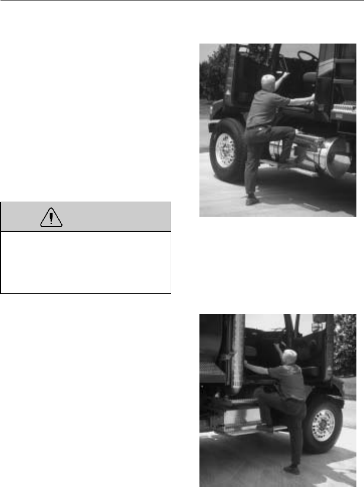
Driver Side Entry/Exit
Open the door. Place any hand-carried
items on the cab floor. Grasp the right grab
handle with your right hand and the left
grab handle with your left hand. Put the
right foot fully on the bottom step and pull
yourself up to the opening.
Slide hands up on the handles, if necessary.
Put the left foot on the top step and step up.
Step into the cab with the right foot first.
To exit, reverse the process. Do not attempt
to exit the cab while carrying any items in
your hands.
WARNING
On vehicles without side fairings, al-
ways make sure that the battery box
cover is securely fastened before step-
ping up. Failure to fasten the cover may
lead to personal injury.
W0001911
Passenger Side Entry/Exit
Open the door. Place any hand-carried
items on the cab floor. Grasp the left grab
handle with your left hand and the right
grab handle with your right hand. Put the
left foot fully on the bottom step and pull
yourself up to the opening.
Slide hands up on the handles, if necessary.
Put the right foot on the top step and step
up.
Step into the cab with the left foot first.
To exit, reverse the process. Do not attempt
to exit the cab while carrying any items in
your hands.
W0001910
24 Vehicle Access
Behind the Cab Entry
When trailer air and electrical connections
can not be coupled from the ground, Fed-
eral Regulations require commercial
carriers to provide back-of-cab access steps,
grab handles and plates.
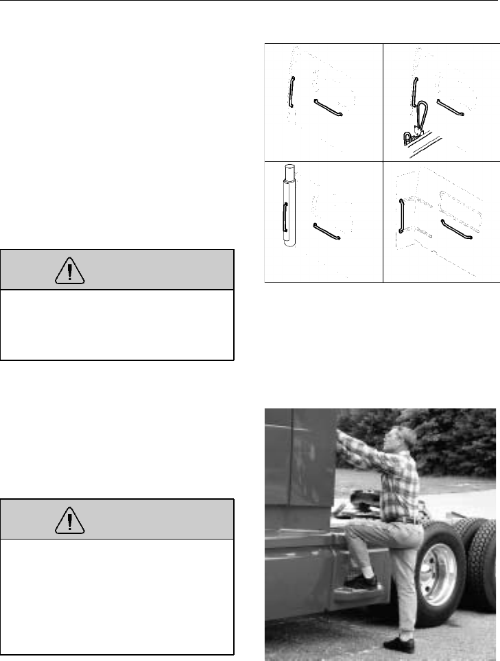
Depending on what option is chosen, grab
handles are available in many variations. In
each case, make sure to always have three
limbs (one foot and two hands or two feet
and one hand) in contact with the vehicle at
all times when entering or exiting the area
behind the cab.
WARNING
Wearing shoes with soles that are dirty
or wet increases the chance of slipping
or falling. Be careful when entering the
back-of-cab area with dirty or wet soles.
W8001363
Grasp the grab handle to the left with both
hands. Put the left foot onto the bottom
step and pull yourself up. Put the right foot
on the top step and step onto the deck plate
with the left foot.
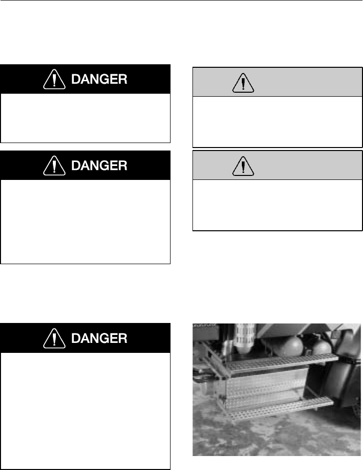
WARNING
Always perform trailer hook-ups while
standing on the ground. Do not climb
on top of fuel tanks or frame rails to
hook up or disconnect trailer air lines
and electrical cord. Use only the metal,
slip resistant steps provided to prevent a
slip and fall injury.
W9000077
Vehicle Access 25
Stand on the ground when connecting the
air and electrical connections to the trailer.
W5000713
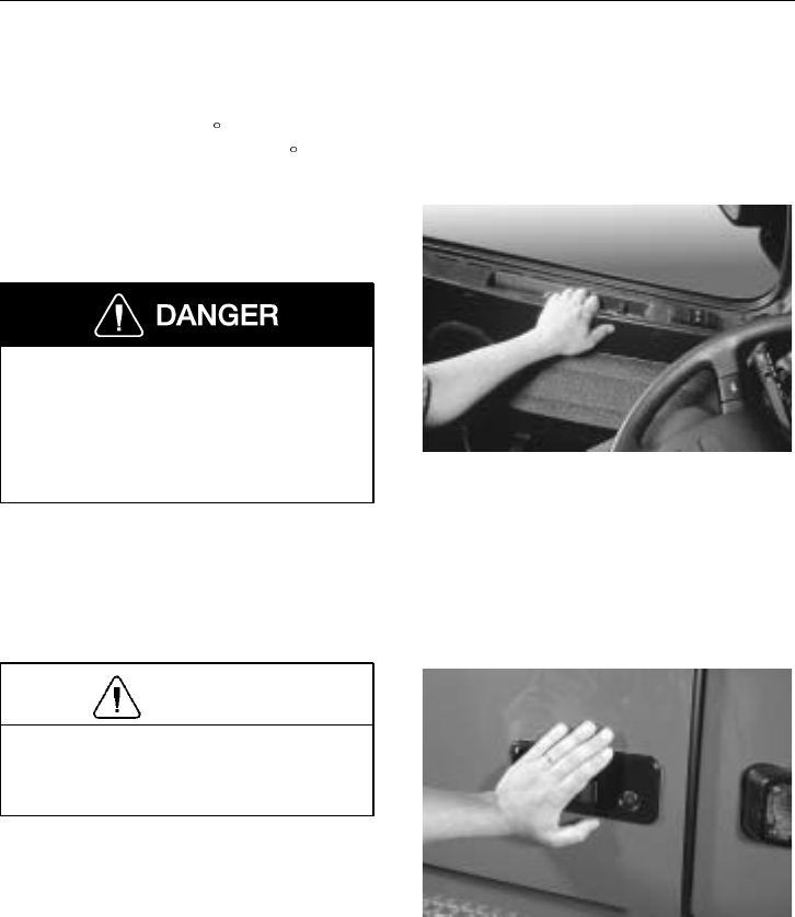
26 Vehicle Access
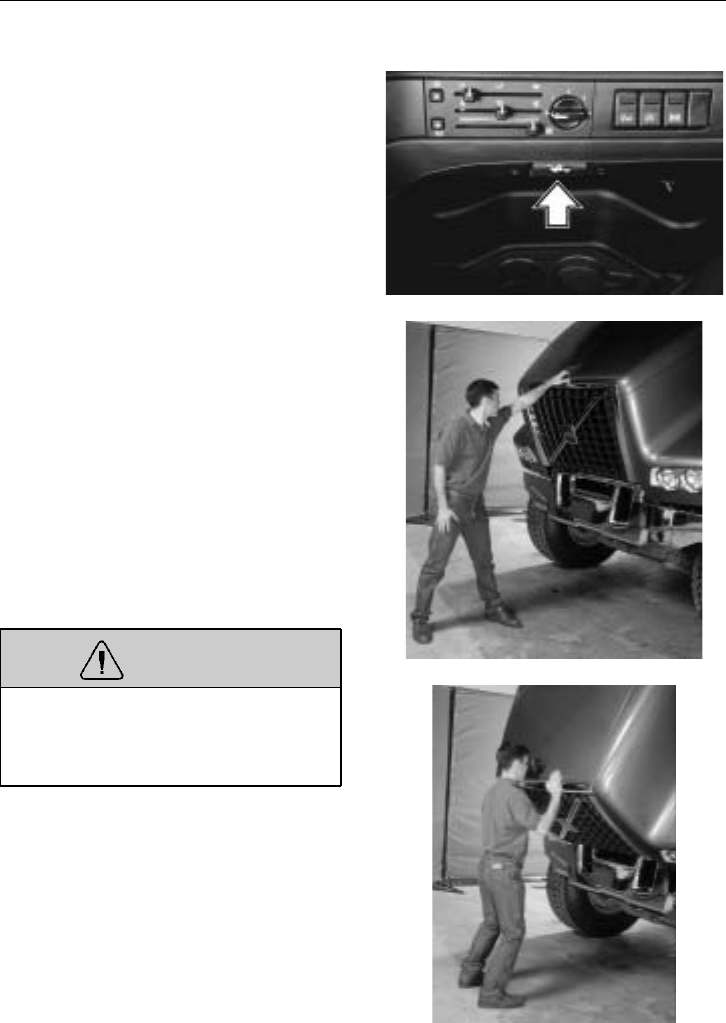
Hood
The hood is locked down by two latches,
one on each side of the back end of the
hood. The latches are operated by a handle
on the bottom edge of the dashboard.
Pull the bottom of the handle out to release
hood. The hood will be raised about two
inches off its resting position and remain
there.
Make sure the hood can be opened fully
without hitting anything. Stand sideways in
front of the hood with feet in line with the
vehicle. Place feet well apart and grasp the
recessed handle in the front part of the
hood. Transfer the body weight by leaning
away from the hood. Lift the hood until it
is past the balance point. Release the hood
and let it complete the opening movement
unaided.
Two restraint cylinders will engage during
the last part of the opening. The cylinders
will slow and dampen the hood down to its
resting position.
WARNING
Make sure that no one is in the way of
the hood when closing. The hood could
injure a person in the way while being
lowered.
To close the hood, stand with feet well
apart and place the hands along the front
edge of the hood. Bend the knees and let
the leg muscles do the work when lifting.
Raise the hood up to the halfway point.
Carefully guide the hood down with
enough speed that the hood latches lock the
hood in place when it comes to its normal
resting position.
W8000986
W0001912
W0001913
Vehicle Access 27
Manual Hood Opening
In the event of a malfunction in the hood
opening mechanism, the hood latches can
be manually operated through an opening
in the wheelwell splash shield. The opening
is normally covered by a plate.
To access the opening, remove the two
screws using a T30 Torx screwdriver. Re-
move the cover plate.
W8002389
The hood latch can now be accessed
through the hole. Operate the latch manu-
ally by pushing the lever in towards the
engine. Do the same on the other side.
W8000981

28 Pre-Trip Inspection and Daily Maintenance
General
Before working on or inspecting a vehi-
cle, set the parking brakes, place the
transmission in neutral and block the
wheels. Failure to do so can result in un-
expected vehicle movement and can
cause serious personal injury or death.
Safety is the most important and obvious
reason for doing a pre-trip inspection. Fed-
eral and state laws require inspection done
by the driver. Federal and state inspectors
also inspect commercial vehicles. An un-
safe vehicle can be placed “out of service”
until the driver or owner corrects the
deficiency. Owners and operators should fa-
miliarize themselves with sections 49 CFR
396.11 and 396.13 concerning Federal re-
quirements for vehicle inspection. Certain
other laws may also apply.
Section 49 CFR 396.13 states that all motor
carrier drivers must complete a written re-
port at the end of each work day for each
vehicle operated, covering most of what is
covered in the pre-trip list. The report
should list all defects or deficiencies dis-
covered by the driver. Doing a pre-trip
inspection prepares for the end-of-work re-
port.
Starting on the next page are suggested
guidelines to be used in performing truck,
tractor and trailer pre-trip inspections. De-
pending on the application of the vehicle
being used, these guidelines should be
modified to include other necessary inspec-
tion points. For example, steps and grab
handles should be checked daily on refuse
trucks because the operator is getting in
and out of the cab more frequently.
If any component or system does not pass
this inspection, it must be corrected before
operating the vehicle. Whenever equipment
requires adjustment, replacement, repair or
lubrication, refer to the Service Manuals or
contact a Volvo Truck dealer for the correct
procedures, specifications and intervals.
Take your time going through the pre-trip
inspection. Remember that a careful pre-trip
inspection saves time by eliminating un-
scheduled stops for correcting a faulty item.
The following information has been
provided by the American Trucking Associ-
ation as developed by the D.O.T. Office of
Motor Carriers (BMCS).
Pre-Trip Inspection and Daily Maintenance 29
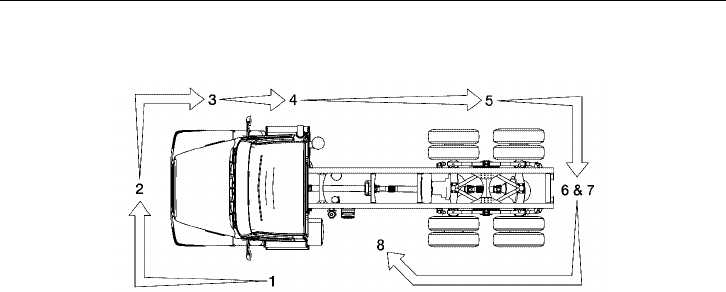
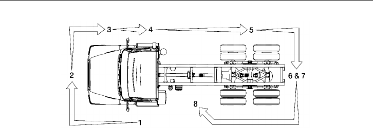
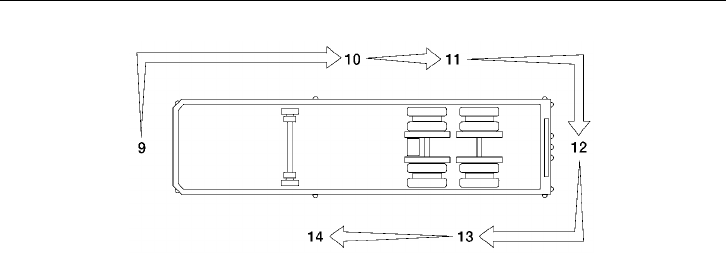
Pre-Trip Inspection Quick List
W1000145
Inspect the vehicle in a circular manner as shown in the
illustration. Numbers between parentheses in the list, re-
fer to pages in this manual where component function
and necessary inspection is explained in greater detail.
Approaching the Vehicle
•Check under the vehicle for oil, fuel,
coolant leaks or other signs of damage.
•Check body surfaces for signs of
breaks or damage.
Preparation
•Open drain cocks on air tanks to let
the tanks drain ( page 234).
•Chock wheels on vehicle and, if
hooked up, trailer.
•Close air tank drain cocks.
•Start the engine and let the air pres-
sure build up to normal ( page 224).
Stop engine.
•Switch on parking lights and four-way
flashers ( page 94).
•Apply parking brakes ( page 229).
•Release the hood latches ( page 26).
Raise hood.
Step 1: Left Side Of the Cab
Left Front Wheel
•Check condition of wheel rim. Espe-
cially look for cracks, missing
lockrings, bent or broken studs,
clamps or lugs.
•Check condition of tire: properly in-
flated, no serious cuts, bulges, tread
wear or any signs of misalignment;
valve stem not touching wheel, rim or
brake drum; valve cap in place.
•Check wheel bearing and hub: no ob-
vious leaking on outside or inside
wheel. Verify correct oil level in hub.
Left Front Suspension
•Check condition of spring, spring
hangers, shackles, U-bolts: no cracks,
breaks or shifting.
•Check shock absorber condition.

30 Pre-Trip Inspection and Daily Maintenance
Step 1: Left Side Of the Cab (cont.)
Left Front Brake
•Condition of brake drum. With brakes
released, look for a noticeable gap be-
tween lining and drum (This check
cannot be made if dust covers are in
place).
•Condition of brake air hose.
•Check brake chamber mounting bolts
and bracket.
•Check slack adjuster and chamber
pushrod travel.
Condition of Front Axle and Steering Sys-
tem, Left Side
•No loose, worn, bent, damaged or
missing parts.
Under Hood, Left Side
•Check coolant hose condition.
•Check condition of fan drive belts.
•Check engine and surrounding areas
for coolant, oil and fuel leaks.
•Check wiring harnesses for signs of
damage.
Step 2: Front Of Cab Area
Condition of Windshield
•Check for damage and clean if dirty
( page 44 ).
•Check windshield wiper arms for
proper spring tension.
•Check wiper blades for any damage,
“dead” rubber and securement to arm.
Lights and Reflectors
•Lower hood and inspect parking,
clearance and identification lights on
hood and cab. They should be clean,
operating and of the proper color.
•Reflectors clean and proper color.
•Turn on headlights. High and low
beams should be operating and lenses
clean. If equipped, check daytime run-
ning lights.
•Left and right front turn signal lights
clean, operating and proper color.
Raise hood.
Grille
•Check that charge air cooler and radia-
tor or bugscreens are clean and
undamaged.
Step 3: Right Side Of Cab Area
Right Front Wheel
•Check condition of wheel rim. Espe-
cially look for cracks, missing
lockrings, bent or broken studs,
clamps or lugs.
•Check condition of tire: properly in-
flated, no serious cuts, bulges, tread
wear or any signs of misalignment;
valve stem not touching wheel, rim or
brake drum; valve cap in place.
•Check wheel bearing and hub: no ob-
vious leaking on outside or inside
wheel. Verify correct oil level in hub.

Pre-Trip Inspection and Daily Maintenance 31
W1000145
Step 3: Right Side Of Cab Area (cont.)
Right Front Suspension
•Check condition of spring, spring
hangers, shackles, U-bolts: no cracks,
breaks or shifting.
•Shock absorber condition.
Right Front Brake
•Condition of brake drum. With brakes
released, look for a noticeable gap be-
tween lining and drum (This check
cannot be made if dust covers are in
place).
•Condition of brake air hose: check for
any chafing.
•Check brake chamber mounting bolts
and bracket.
•Check slack adjuster and chamber
pushrod travel. With brakes applied or
released, look for conspicuously dif-
ferent positions of the slack adjusters.
Condition of Front Axle and Steering Sys-
tem, Right Side
•No loose, worn, bent, damaged or
missing parts.
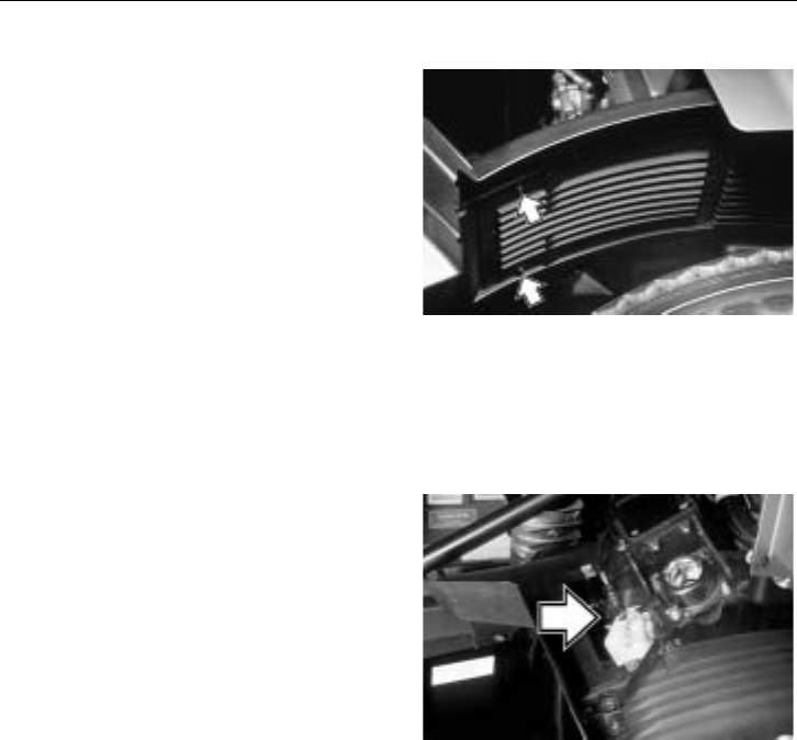
Under Hood, Right Side
•Check condition of coolant and heater
hoses.
•Check condition of fan drive belts.
•Check engine and surrounding areas
for coolant, oil and fuel leaks.
•Check fuel separator sight glass and
drain if necessary. Check for leaks.
•Check wiring harnesses for signs of
damage.
•Check air filter with brackets and
hoses for loose connections or dam-
age. Check filter gauge, if mounted on
the filter.
Step 4: Right Saddle Tank Area
Right Fuel Tank(s)
•Securely mounted and not damaged or
leaking.
•Fuel lines secure and not leaking.
Check that shut-off valves are open.
•Tank(s) full of fuel. Cap on and secure.

32 Pre-Trip Inspection and Daily Maintenance
Condition of Visible Components
•Rear of engine: not leaking.
•Transmission: not leaking. If equipped
with oil cooler, check for leaks or that
air-to-air cooler is not blocked.
•Check drive shaft.
•Exhaust system: secure, not leaking,
not touching wires, fuel or air tubing.
•Frame and cross members: no bends,
cracks or breaks.
•Air tubing and electrical wiring: se-
cured against snagging and chafing.
Step 5: Right Rear Vehicle Area
Dual Wheels, One Or Two Axles
•Check condition of wheels and rims.
Especially look for cracks, missing
lockrings, bent or broken spacers,
studs, clamps or lugs.
•Check condition of tires: properly in-
flated, no serious cuts, bulges, tread
wear or any signs of misalignment;
valve stems not touching wheels, rims
or brake drums; valve caps in place
and no objects stuck between the
wheels.
•Check that both tires are of same type,
for example, not mixed radial and bias
type and that their circumferences are
matched.
•Check wheel bearing and hub: no obvi-
ous leaking on outside or inside wheel.
Suspension
•Check condition of springs (leaf or
air), spring hangers, shackles and U-
bolts.
•Axle alignment.
Brakes
•Condition of brake drums. With brakes
released, look for a noticeable gap be-
tween lining and drum (This check
cannot be made if dust covers are in
place).
•Condition of brake hoses: check for
any chafing.
•Check brake chamber mounting bolts
and brackets.
•Check slack adjusters and chamber
push rod travel. With brakes applied or
released, look for conspicuously dif-
ferent positions of the slack adjusters.
•Check spring brakes.
Step 6: Rear Of Vehicle Area
Frame Area
•Frame or cross members not bent,
cracked or otherwise damaged or
missing.
•Check that air tubing and electrical
lines are properly secured to the frame
with no damage or chafing.
Lights and Reflectors
•Tail lights, brake lights and turn signal
lights: operating, clean and proper
color.
Pre-Trip Inspection and Daily Maintenance 33
W1000145
Step 7: Coupling System Area
Fifth Wheel
•Securely mounted to the frame.
•No missing or damaged parts.
•Check that trunnion and plate are
properly lubricated ( page 265).
Sliding Fifth Wheel
•Mechanism not worn, bent, damaged
or parts missing ( page 267).
•Properly lubricated.
•All locking pins present and locked in
place.
•If air operated: no air leaks.
Air Tubing and Electric Lines Visible From
This Point
•Should be secure from dangling.
•Both air lines and electric line should
be free from damage, oil and grease.
Step 8: Left Saddle Tank and Left Rear
Vehicle Wheels Area
Dual Wheels, One Or Two Axles
•Check condition of wheels and rims.
Especially look for cracks, missing
lockrings, bent or broken spacers,
studs, clamps or lugs.
•Check condition of tires: properly in-
flated, no serious cuts, bulges, tread
wear or any signs of misalignment;
valve stems not touching wheels, rims
or brake drums; valve caps in place
and no objects stuck between the
wheels.
•Check that both tires are of same type,
for example, not mixed radial and bias
type and that their circumferences are
matched.
•Check wheel bearing and hub: no obvi-
ous leaking on outside or inside wheel.
Suspension
•Check condition of springs (leaf or
air), spring hangers, shackles and
U-bolts, no cracks, breaks or shifting.

34 Pre-Trip Inspection and Daily Maintenance
Brakes
•Condition of brake drums. With brakes
released, look for a noticeable gap be-
tween lining and drum (This check
cannot be made if dust covers are in
place).
•Condition of brake hoses: check for
any chafing.
•Check brake chamber mounting bolts
and brackets.
•Check slack adjusters and chamber
push rod travel. With brakes applied or
released, look for conspicuously dif-
ferent positions of the slack adjusters.
•Check spring brakes.
Condition of Visible Components
•Transmission: not leaking.
•Drive shaft: looks OK.
•Exhaust system: secure, not leaking,
not touching wires, fuel or air tubing.
•Frame and cross members: no bends,
cracks or breaks.
•Air tubing and electrical wiring: se-
cured against snagging and chafing.
Left Fuel Tank(s)
•Securely mounted and not damaged or
leaking.
•Fuel lines secure and not leaking.
Check that shut-off valves are open.
•Tank(s) full of fuel. Cap on and secure.
Battery Area
•Open the battery box ( page 245). Bat-
tery box securely mounted to vehicle.
•Batteries secured against movement
( page 245).
•Battery cases not broken or leaking.
Battery cables free from damage.
•Tops of batteries and terminals clean
and free from foreign material.
•If equipped, replace battery lid and
make sure it is securely fastened
( page 245).

Pre-Trip Inspection and Daily Maintenance 35
W1000145
In the Cab
•Check steps and grab handles for
looseness or breakage ( page 22).
Also, clean them if there is any sub-
stance that makes them slippery, which
makes cab entry/exit hazardous.
•Start the engine. If equipped, check
that exhaust rain cap opens when ac-
celerating engine.
•Check gauges and telltale light func-
tion ( page 79).
•Check function of low air warning
( page 85). Check the Graphic Display
for any fault codes ( page 108).
•Check clutch function ( page 222). If
equipped, check for clutch brake func-
tion.
•Check windshield wipers and washers
( page 43) and horns, including back-
up alarm, if equipped.
•Clean inside windshield, door win-
dows and instruments. Clean mirrors.
•Check climate control and defroster
( page 168). If equipped, check mirror
heater.
•Check condition of warning triangles,
fire extinguisher and flares ( page 62).
•Adjust the seat ( page 180). Check
mirror adjustment.
•Check safety belts for function and
damage ( page 49).
•Apply service brakes. After initial
drop, pressure should hold steady, or
increase slightly, with engine at idle.
•Check steering wheel for excessive
free play.
•Check for loose items in the cab. Se-
cure them if necessary.

36 Pre-Trip Inspection and Daily Maintenance
Hooking Up To Trailer
Hook-up Preparation
•Check kingpin and mounting plate on
trailer, free from wear, bends or dam-
age.
•Chock trailer wheels.
Fifth Wheel Or Trailer Hitch
•No visible space between fifth wheel
and trailer ( page 273).
•Locking jaws around the shank and
not the head of kingpin ( page 273).
•Release lever properly seated and
safety latch/lock engaged ( page 274).
•Check all connections to dolly or
trailer hitch and safety chains are se-
cured.
•Check function of trailer air supply
valve and trailer brakes.
Sliding Fifth Wheel
•Check that fifth wheel is not so far
forward that the tractor frame will
strike the landing gear during turns.
Pre-Trip Inspection and Daily Maintenance 37
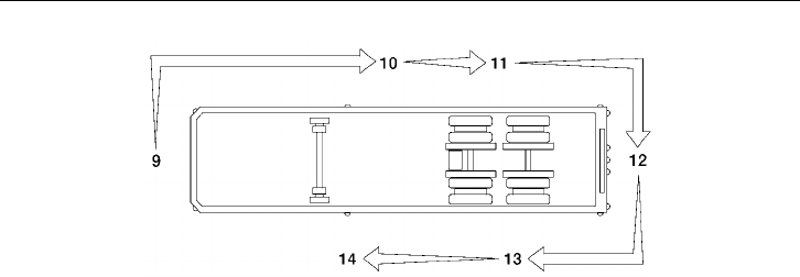
W0001919
NOTE! Refer to the trailer manufacturer’s
manual for specific information on the
trailer checks.
Step 9: Trailer Front Area
Air and Electrical Connections
•Glad hands properly mounted, free
from damage and not leaking.
•Trailer cord receptacle properly
mounted, free of damage; plug prop-
erly seated and safety catch engaged
to prevent accidental disconnect.
•Air and electrical lines properly se-
cured against tangling, snagging and
chafing with sufficient slack for turns.
Step 10: Right Side of Trailer Area
Landing Gear or Dolly Area
•Fully raised; no missing or damaged
parts.
•Crank handle present and secured.
•If power operated, no air/hydraulic
leaks.
Spare Wheel(s)
•Carrier or rack not damaged.
•Spare wheel securely mounted in rack.
•Tire and wheel condition adequate for
a spare: proper size, properly inflated.
Lights and Reflectors
•Trailer side clearance lights: clean, op-
erating and proper color.
•Reflectors clean and proper color.
Frame and Body
•Frame and crossmembers not bent,
cracked, damaged or missing.
•Proper placarding.
•Body parts not damaged or missing.

38 Pre-Trip Inspection and Daily Maintenance
Step 11: Right Rear Trailer Wheel
Dual Wheels, One Or Two Axles
•Check condition of wheels and rims.
Especially look for cracks, missing
lockrings, bent or broken spacers,
studs, clamps or lugs.
•Check condition of tires: properly in-
flated, no serious cuts, bulges, tread
wear or any signs of misalignment;
valve stems not touching wheels, rims
or brake drums; valve caps in place
and no objects stuck between the
wheels.
•Check that both tires are of same type,
for example, not mixed radial and bias
type and that their circumferences are
matched.
•Check wheel bearing and hub: no obvi-
ous leaking on outside or inside wheel.
Suspension
•Condition of springs (leaf or air),
spring hangers, shackles and U-bolts.
•Axle alignment.
•Condition of torque rod arms.
•If equipped with sliding axles, check
position and alignment. Look for dam-
aged, worn or missing parts, all locks
present, fully in place and locked.
•Flexible air tubing not cracked, cut,
crimped or otherwise damaged. Se-
cured against tangling, dragging and
chafing.
Brakes
•Condition of brake drums. With brakes
released, look for a noticeable gap be-
tween lining and drum (This check
cannot be made if dust covers are in
place).
•Condition of brake hoses: check for
any chafing.
•Check brake chamber mounting bolts
and brackets.
•Check slack adjusters and chamber
push rod travel. With brakes applied or
released, look for conspicuously dif-
ferent positions of the slack adjusters.
•Check spring brakes.
Step 12: Rear of Trailer Area
Lights and Reflectors
•Rear clearance, identification and tail
lights clean, operating and proper
color.
•Reflectors clean and proper color.
Cargo Securement
•Cargo properly blocked, braced, tied,
chained, etc.
•Tailboard up and properly secured.
End gates free from damage, properly
secured in stake pockets.
•Canvas or tarp (if required) properly
latched down to prevent water damage,
tearing, billowing or blockage of either
mirrors or tail lights.
•Rear doors securely closed, latched or
locked; required security seals in place.
•Underside guard in place: not cracked,
bent or broken.
Pre-Trip Inspection and Daily Maintenance 39
W0001919
NOTE! Refer to the trailer manufacturer’s
manual for specific information on the
trailer checks.
Step 13: Left Rear Trailer Wheels Area
Dual Wheels, One Or Two Axles
•Check condition of wheels and rims.
Especially look for cracks, lockrings
missing, bent or broken spacers, studs,
clamps or lugs.
•Check condition of tires: properly in-
flated, no serious cuts, bulges, tread
wear or any signs of misalignment;
valve stems not touching wheels, rims
or brake drums; valve caps in place
and no objects stuck between the
wheels.
•Check that both tires are of same type,
for example, not mixed radial and bias
type and that their circumferences are
matched.
•Check wheel bearing and hub: no obvi-
ous leaking on outside or inside wheel.
Suspension
•Condition of springs (leaf or air),
spring hangers, shackles and U-bolts.
•Axle alignment.
•Condition of torque rod arms.
•If equipped with sliding axles, check
position and alignment. Look for dam-
aged, worn or missing parts, all locks
present, fully in place and locked.
•Flexible air tubing not cracked, cut,
crimped or otherwise damaged. It
should be secured against tangling,
dragging and chafing.
Brakes
•Condition of brake drums. With brakes
released, look for a noticeable gap be-
tween lining and drum (This check
can not be made if dust covers are in
place).
•Condition of brake hoses: check for
any chafing.
•Check brake chamber mounting bolts
and brackets.
•Check slack adjusters and chamber
push rod travel. With brakes applied or
released, look for conspicuously dif-
ferent positions of the slack adjusters.
•Check spring brakes.

40 Pre-Trip Inspection and Daily Maintenance
Step 14: Left Side of Trailer Area
Landing Gear or Dolly Area
•Fully raised; no missing or damaged
parts.
•Crank handle present and secured.
•If power operated, no air/hydraulic
leaks.
Spare Wheel(s)
•Spare wheel securely mounted in rack
with no damage to rack.
•Tire and wheel condition adequate for
a spare: proper size, properly inflated.
Lights and Reflectors
•Trailer side clearance lights: clean, op-
erating and proper color.
•Reflectors clean and proper color.
Frame and Body
•Frame and crossmembers not bent,
cracked, damaged or missing.
•Proper placarding.
•Body parts not damaged or missing.
Before Leaving the Parking Area
•Remove chocks from the wheels.
•Test trailer hook-up by slowly pulling
while applying the trailer brakes with
the trailer brake hand control valve.
•Test the service brakes before leaving
the parking area.
•Test parking brakes by stopping on a
20% grade and applying the parking
brakes. The parking brakes shall hold
the combined vehicle and trailer with-
out moving.
Pre-Trip Inspection and Daily Maintenance 41
Daily Maintenance
The following should be checked daily in
addition to doing the pre-trip inspection of
the truck or tractor and trailer.
While checking the fluid levels, visually in-
spect hoses, pipes and their connections for
signs of leakage. Inspect the ground under
engine, transmission and rear axle(s) for
signs of leakage.
Before working on or inspecting a vehi-
cle, set the parking brakes, place the
transmission in neutral and block the
wheels. Failure to do so can result in un-
expected vehicle movement and can
cause serious personal injury or death.
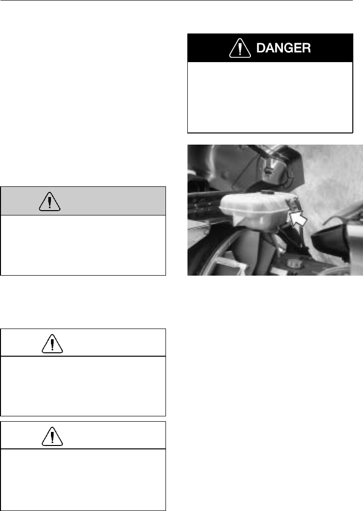
Check coolant level in the coolant tank.
The level should be above the minimum
mark shown on the side of the tank.
WARNING
Do not remove the cap to the surge tank
while the engine and radiator are still
hot and under pressure. Scalding fluid
and/or steam may be blown out under
pressure if the cap is taken off too soon.
If the coolant level is low, add more
coolant to the tank so the level is above the
minimum mark. Coolant should be filled
through the cap in the middle of the tank.
CAUTION
Add only pre-mixed coolant made up of
50% clean water and 50% antifreeze.
See the “Operator’s Manual, Mainte-
nance & Engine” for more detailed
information.
CAUTION
Engines equipped with automatic start
systems can start automatically. Alarm
sounds before automatic start. Failure to
turn off ignition before working on fan
or belts can result in personal injury.
W2003475
42 Pre-Trip Inspection and Daily Maintenance
WARNING
Keep yourself clear of all moving or hot
engine parts. A hot engine can cause se-
rious burns.
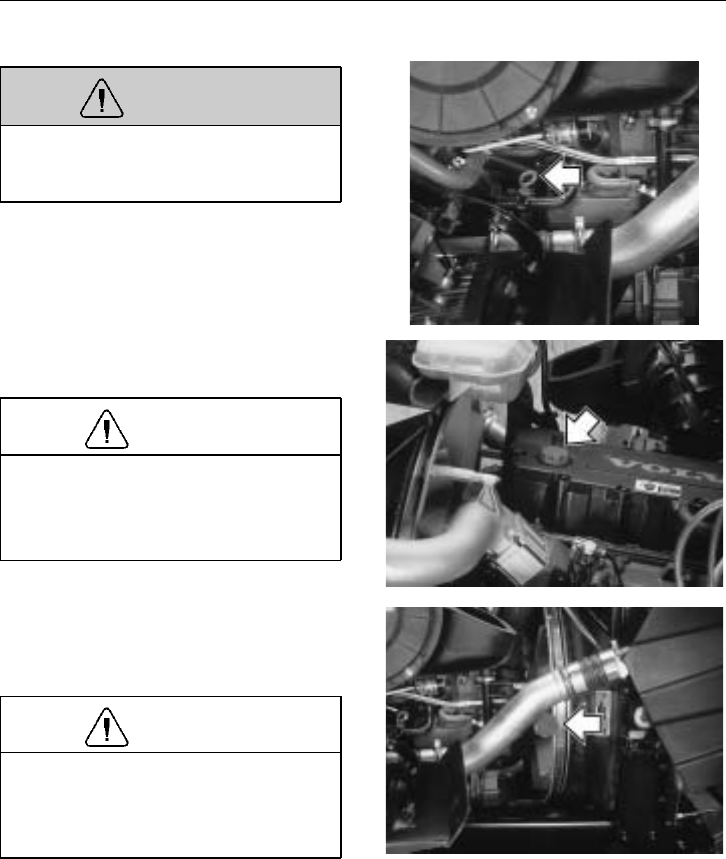
Check oil level in the engine with the dip-
stick. The oil level should be between the
minimum and maximum marks on the dip-
stick. Do not overfill!
See the “Operator’s Manual, Maintenance
and Engine” for correct types of oil used in
Volvo engines.
CAUTION
If the vehicle is equipped with an aero-
dynamic bumper, do not step on or press
in between the bumper and the wheel.
Breakage or damage may result.
W2003508
W2003476
To add oil to a D12 engine, remove oil cap
on the valve cover and fill through the hole.
There is also a right-side oil fill.
CAUTION
Make sure the oil added is the same
type of oil that is in the engine. The
wrong type of oil could accelerate wear
on engine if not suited for application.
W2003486
Pre-Trip Inspection and Daily Maintenance 43
Check fluid level in the clutch fluid reser-
voir. Fluid level should be between the
level marks on the reservoir.
If fluid needs to be added, use brake fluid,
DOT 4.
W4000726
Check level in the windshield washer reser-
voir. If washer fluid needs to be added, use
a commercially reputable washer fluid that
has good cleaning capability and does not
freeze in cold weather.
Total reservoir capacity is 3.3 gallons
(12.5 liters). An indicator will appear on
the diagnostic display when there is
approximately 1.4 gallons (5.3 liters) re-
maining in the reservoir. W8000985
Check that windshield wipers and washer
are working properly.
The windshield washer spray should cover
the windshield well. The wipers should
clean the windshield in a couple of strokes
and should not leave any streaks.
W3000874
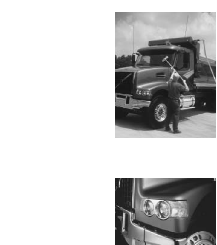
44 Pre-Trip Inspection and Daily Maintenance
If the windshield needs an overall cleaning,
use a long handled cleaning sponge and
squeegee.
Clean the side windows in the same way
with a long handled sponge and squeegee.
W8002766
Check all lights for proper function:
•Headlights
•Daytime running lights
•Parking and marker lights
•Stoplights
•Turn signals
W3004425
NOTE! Make sure that all fluid levels are
at their proper levels. If the fluids are not at
their proper levels, add as necessary. Refer
to the “Operator’s Manual, Maintenance
and Engine” for information on what types
of fluids are recommended for your Volvo
vehicle.
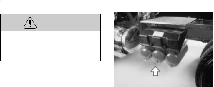
Pre-Trip Inspection and Daily Maintenance 45
WARNING
When draining the air tanks, do not look
into the area of the draining air. Dirt or
sludge particles may be in the air stream
that could cause eye injury.
Empty out the air tanks daily. With the air
system fully charged and with the engine
shut off, listen for air leaks.
W5001203
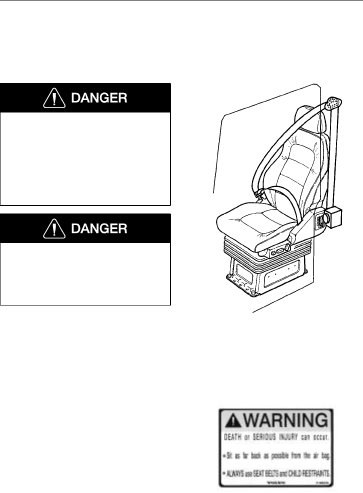
46 Additional Safety Features
Safety Belts
General
Safety belts must be properly worn at all
times by the driver and all passengers
while the vehicle is in motion even if
the vehicle is equipped with a Supple-
mental Restraint System (SRS or air
bag). Failure to do so can result in seri-
ous personal injury or death in the event
of a collision.
Fasten the safety belt before starting to
drive. Trying to fasten the safety belt
while the vehicle is moving may lead to
an accident, causing serious personal in-
jury or death.
Safety belt assemblies installed in this vehi-
cle meet FMVSS 209, “Type 1” and “Type
2” requirements. They are recommended
for all persons weighing over 50 lb (25 kg).
W8001834
A child restraint system should also be pro-
vided for each child weighing 50 lb (25 kg)
or less. It should meet the requirements of
FMVSS 213, “Child Restraint System.”
Carefully read and follow all manufac-
turer’s instructions on installation and use.
Make certain the child remains in the re-
straint system at all times while the vehicle
is in motion. W8002741
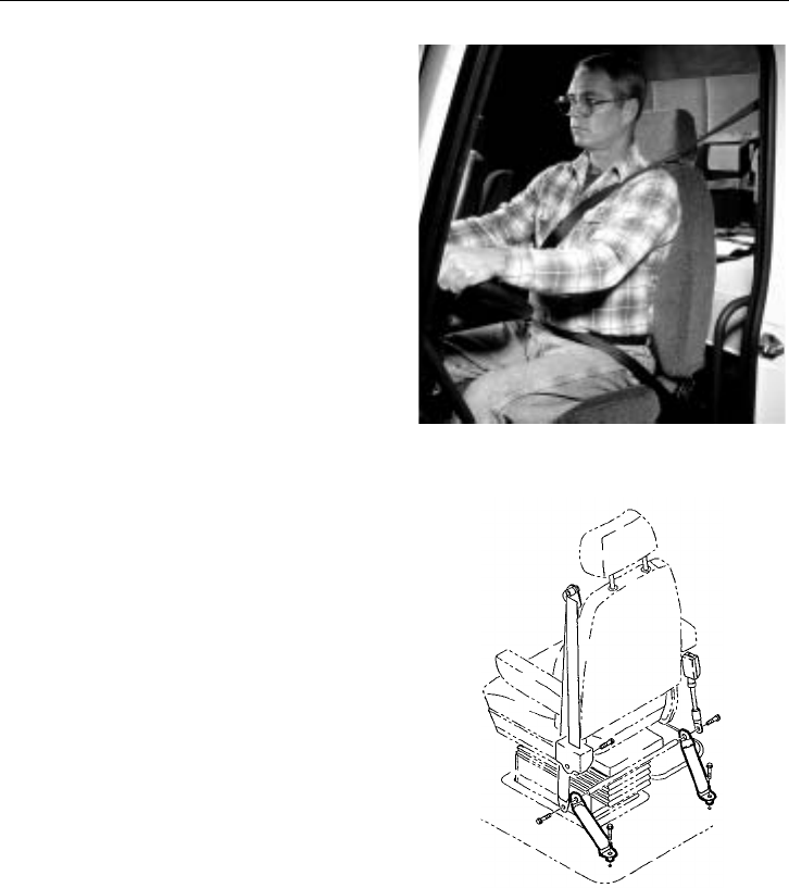
Additional Safety Features 47
Safety belts must be worn by the driver and
all passengers at all times. Before adjusting
or fastening the safety belt, move the seat
forward or rearward and adjust the seat
height as necessary. Sit erect and adjust the
seat cushion and seat back for a comfort-
able driving position. In the event of a
collision, a correct driving position maxi-
mizes the effectiveness of the safety belt.
There are both Federal and State laws gov-
erning the use of safety belts. As laws
differ from state to state, make yourself fa-
miliar with the current rules.
W8001077
Tether straps are installed on some
suspension-type seats. Tether straps help se-
cure the seat to the floor and are intended
to restrain the seat and safety belt in case
of an accident or sudden stop.
The tethers are not adjustable and do not
need any adjustment.
W8001387
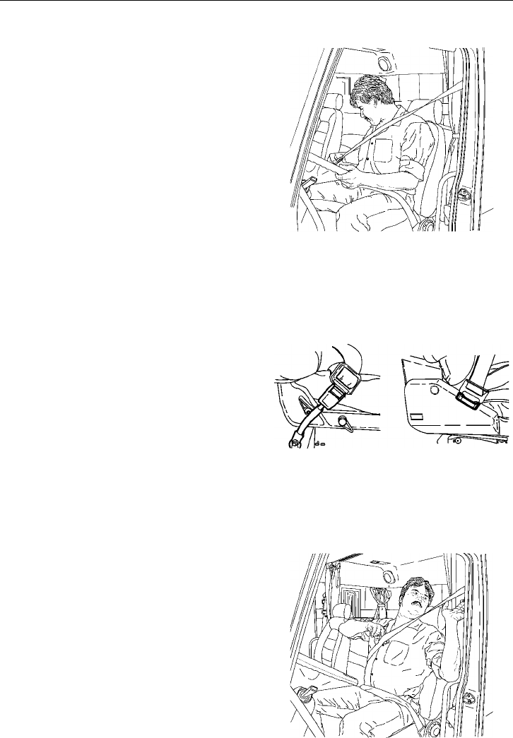
48 Additional Safety Features
Operating the Safety Belt
To fasten the safety belt, pull the belt out
from the retractor and insert the latch into
the buckle. Verify proper lock of the latch
by pulling on the latch.
Adjust the slack by pulling on the top part
of the belt until the lower part, or the part
that crosses the lap, is snugly adjusted. Re-
lease the top part and let the retractor pull
the belt in.
The lap portion of the safety belt should be
worn low across the pelvic region (hip
bone) and adjusted snugly. Never adjust the
lap belt across the abdomen. A push button
on the buckle is used to release the safety
belt latch by pushing in the button release
on the buckle.
W8001835
The buckle portion of the safety belt sys-
tem is different depending on the seat
option chosen. The National Standard and
Comfort seat has a separate buckle that is
attached to a floor anchor by a seat strap.
This seat strap is not adjustable, and does
not need to be adjusted.
The buckle for the Volvo seat is part of the
seat frame.
W8001836
If a comfort clip is used on the safety belt,
always adjust the latch so that there is a
maximum of 1 in. (25 mm) slack between
the belt and chest (about the width of two
fingers). If a larger slack is allowed, the ef-
fectiveness of the safety belt is decreased in
the event of a collision. Operation of the
clip is described on page 54.
Make sure the safety belt is completely re-
tracted and out of the way when not in use.
W8001837
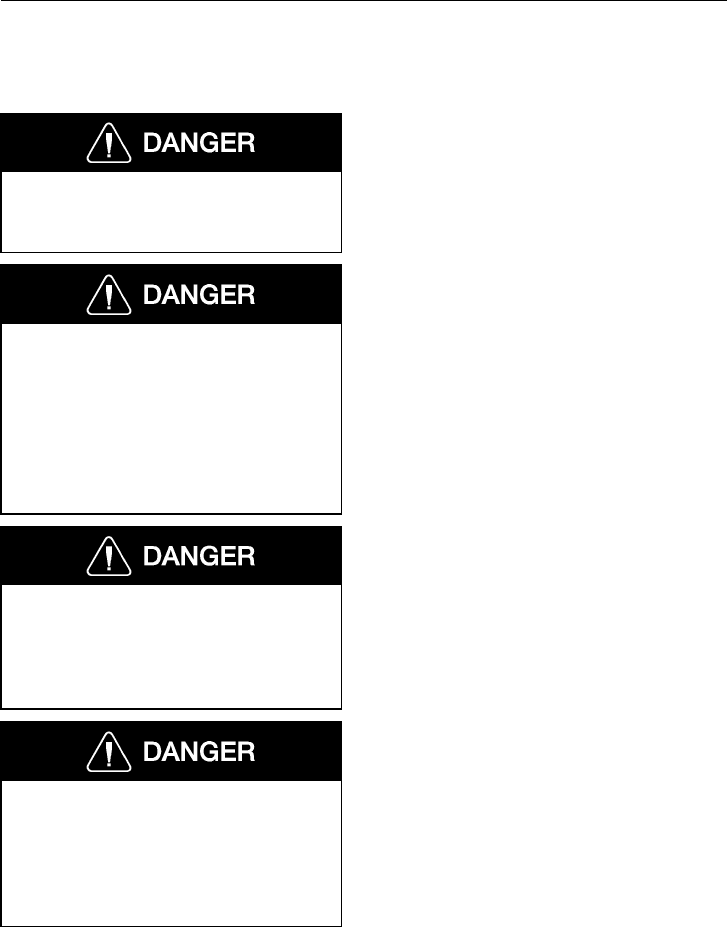
Additional Safety Features 49
Inspection
Failure to properly inspect and maintain
the safety belts can cause serious per-
sonal injury or death.
It is critical that any time a vehicle has
been involved in an accident, the entire
safety belt system must be replaced in
the vehicle (which also includes the
sleeper bunk restraints) if they were in
use at the time of the accident. Failure
to replace the safety belt system may re-
sult in serious injury or death.
A damaged safety belt, whether visibly
damaged or not, could result in serious
personal injury in the event of an acci-
dent. The safety belt systems should be
replaced at least every five years.
Do not bleach or re-dye the color web-
bing because it may cause a severe loss
of belt strength. This loss of strength
could allow the safety belt to break
under stress, thus resulting in severe per-
sonal injury or death.
Check the belts, buckles, latch plates, re-
tractors, anchorages, and guide loops to
ensure that they are working properly. Look
for loose/damaged parts (without disassem-
bling) that could keep the restraint system
from working properly. If the safety belt,
retractor and hardware were in use during a
collision, they must be replaced. The re-
straint system anchorage fasteners must be
replaced if necessary. If there is any doubt
about the restraint system’s effectiveness,
replace the entire safety belt assembly.
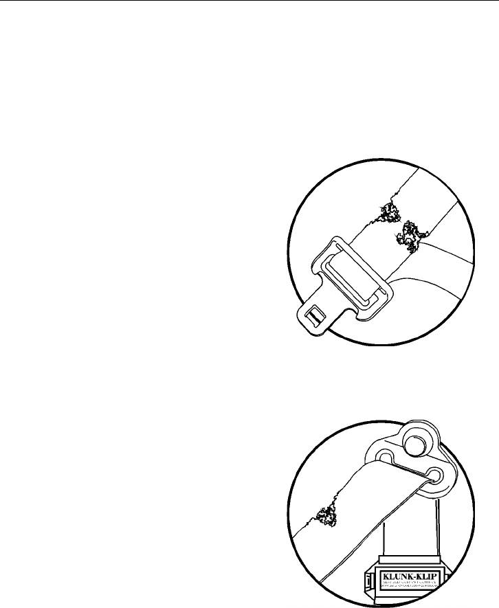
50 Additional Safety Features
The following maintenance guidelines de-
tail how to inspect safety belts and tethers
for cuts, fraying, extreme or unusual wear
of the webbing, etc., and damage to the
buckle, retractor, hardware or other factors
which indicate that safety belt system re-
placement is necessary.
Check the web wear at the buckle/latch
area. The webbing must be closely exam-
ined to determine if there are any cuts,
fraying or extreme wear in the webbing.
Cuts, fraying or excessive wear would indi-
cate the need for replacement of the safety
belt system.
W8001406
The D-loop web guide is an area where al-
most constant movement of the safety belt
webbing occurs because of the relative
movement between the seat and the cab.
This constant movement forms an area
where wear will often occur. The webbing
must be closely examined to determine if
there are any cuts, fraying or extreme wear
in the webbing. Cuts, fraying or excessive
wear would indicate the need for replace-
ment of the safety belt system.
W8002478
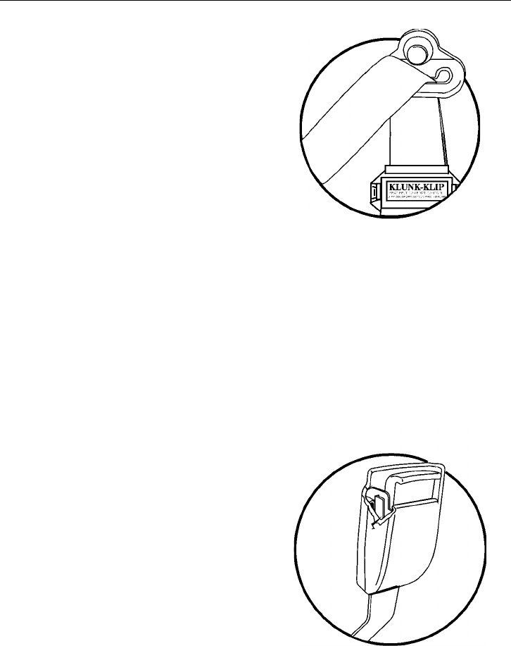
Additional Safety Features 51
Check to make sure that the D-loop web
guide is rotating properly. If the guide is
not rotating properly, the webbing will pull
at the wrong angle through the guide, ac-
celerating wear.
W8002477
If equipped, check the comfort clip for
cracks or possible damage. Make sure that
it works properly.
Check the buckle by inserting the latch and
verifying proper operation. Determine if the
latch plate is worn or deformed. Check the
buckle and latch casing for cracks or
breakage.
W8001404
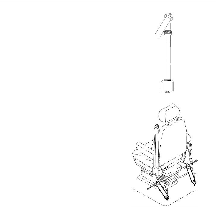
52 Additional Safety Features
The retractor web storage device is
mounted on the B-pillar, just behind the
door in the cab. The retractor is the heart of
the safety belt system and can be damaged
if abused, even unintentionally. Check the
retractor web storage device operation to
ensure that it is not locked and that it spools
out and retracts the webbing properly.
W8002481
If tethers are being used to anchor the
safety belts to the floor, make sure that they
are properly attached to the seat. Tethers
must also be inspected for web wear and
proper tightness of mounting hardware.
W8001387
All hardware for safety belt mounting
points should be evaluated for corrosion.
All attachment points of the system should
be checked for tightness of mounting
hardware.
Check the web in areas exposed to ultra-
violet rays from the sun or extreme dust or
dirt. If the original color of the web in
these areas is extremely faded, the physical
strength of this web may have deteriorated.
If this condition exists, replace the safety
belt system.

Additional Safety Features 53
Important Facts About Safety Belts in Heavy Trucks
The high mileage associated with heavy
trucks, the continual relative movement of
the seat with the cab, the possible contact
with the vehicle seat or other parts of the
cab structure, and the potential exposure of
this safety belt to severe environmental con-
ditions make it crucial to inspect the seat
belt system regularly. It is recommended
that the system is inspected every 15 000
miles (24 000 km) or more often if the ve-
hicle is exposed to severe environmental or
vocational conditions. Any safety belt sys-
tem that shows cuts, fraying, extreme or
unusual wear, significant discolorations due
to ultra-violet ray exposure, dusty-dirty
conditions, abrasion to the safety belt web-
bing or damage to the buckle, latch plate,
retractor, hardware or any other obvious
problem should be replaced immediately,
regardless of the mileage.
Once replacement of the safety belt has
been determined necessary, be certain that
it is replaced only with a Volvo original re-
placement safety belt. See your authorized
Volvo Truck dealer for replacement. Your
Volvo safety belt system has been devel-
oped and tested specifically for heavy
trucks. Replace it only with the exact same
design that the vehicle was equipped with.
If the inspection indicates that any other
part of the safety belt system requires re-
placement, the entire belt system must be
replaced. An installation guide is attached
to every replacement system, entitled
“Three-Point Safety Belt Installation
Guide.” There are separate safety belt
instruction guides for suspension and sta-
tionary seats. Use the proper guide for your
type of seat and follow the instructions
very closely. It is vitally important that all
components are mounted back in the same
positions as the original components that
were removed. This will maintain the de-
sign integrity of the mounting points for the
safety belt assembly.
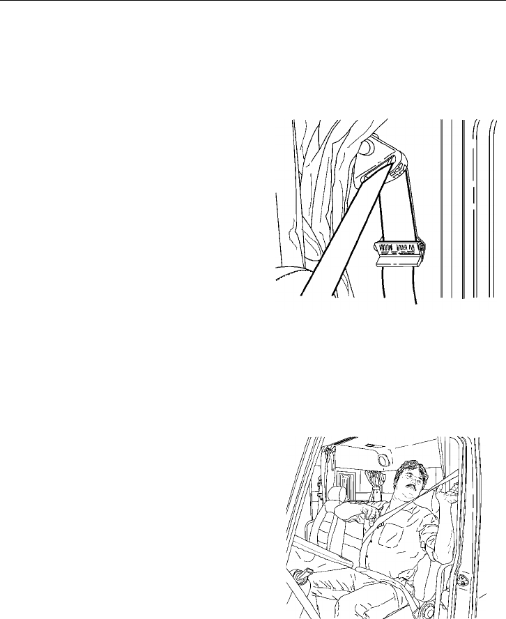
54 Additional Safety Features
Comfort Clip Operation
When provided, the comfort clip is located
on the shoulder strap just below the D-ring.
When adjusting the comfort clip, the fol-
lowing procedure must be followed for
proper adjustment:
1 Pull out only enough webbing to allow
slight pressure to the shoulder and
chest. Allow no more than a 1 in.
(25 mm) slack when measured be-
tween the chest and the belt.
2 To activate the clip mechanism feature,
lift the lever up to clamp the webbing
in place.
NOTE! When the safety belt is not in use,
the clip should be in the open position to
allow the seat belt to retract to its proper
position. Also make sure that the adjust-
ment of the comfort clip does not interfere
with the operation of the safety belt.
W8002388
Open position
Always adjust the clip so that there is a
maximum of 1 in. (25 mm) of slack be-
tween the belt and chest (about two fingers
width). If a larger slack is allowed, the ef-
fectiveness of the safety belt is decreased in
the event of a collision.
W8001837

Additional Safety Features 55
SRS Airbag
WARNING
The SRS airbag is intended to supple-
ment — not replace — the standard
safety belt. The airbag is not deployed
when the truck is hit from behind, from
the side or if it rolls over. For best pro-
tection, sit in a normal, upright position.
Always wear the safety belt.
For added safety, the vehicle may be
equipped with an airbag or SRS (Supple-
mental Restraint System) as a supplement
to the standard three-point anchored safety
belt. The SRS is designed to reduce the risk
of injury to the driver’s face and upper part
of the body. Together with the safety belt,
the airbag helps prevent the driver from be-
ing thrown against the steering wheel,
windshield or other hard surfaces in the cab.
The Volvo SRS Airbag provides increased
protection in frontal collisions, where the
vehicle collides with a fixed or heavy object
with enough force to activate the sensors
which then activates the airbag. Damage to
the vehicle is not always proportional to
whether the SRS Airbag deploys or not.
The SRS Airbag is not designed to be acti-
vated with:
•Collision from the sides
•Collision from the rear
•Rolling over
•Head-on collisions at low speed or
against soft objects such as bushes,
snow drifts, etc.
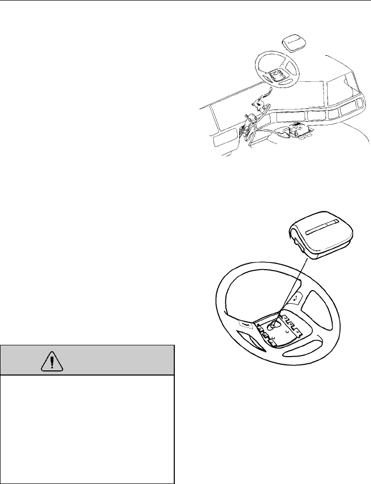
56 Additional Safety Features
SRS System
The inflatable airbag is folded into the cen-
ter of the steering wheel. It inflates in the
event of a serious collision above a certain
level, where the angle of impact, crash
severity, speed and nature of the object in-
volved in the collision all play a part in
whether or not the airbag is activated.
T8006849
The system consists of a gas generator sur-
rounded by the inflatable airbag. In the
event of a sufficiently violent collision, a
control unit activates the gas generator ig-
nitor and the airbag inflates and heats up at
the same time. To cushion the impact, the
airbag deflates when compressed. This also
releases some non-toxic smoke into the
cab. The entire sequence, from inflation to
deflation of the airbag, takes a few tenths
of a second.
WARNING
Never attempt to drive with a deployed
airbag. With the bag hanging out of the
hub of the steering wheel, the truck may
be more difficult to steer. In addition,
other safety systems may be damaged.
Continuous exposure to the smoke and
dust created during the deployment of
the airbag can cause irritation to the skin
and eyes.
T8006855
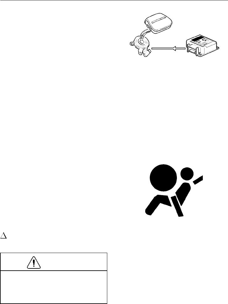
Additional Safety Features 57
The SRS system is continually monitored
by the control unit. A control unit is
mounted on a bracket above the engine
cover which detects deceleration. The con-
trol unit also contains a standby power unit
which can supply the system with power
for a short time, should the normal supply
be broken.
If the control unit detects a sufficiently vio-
lent deceleration (collision), the system is
activated. The gas generator triggers and
fills the bag with a non-toxic gas within a
few hundredths of a second. During a colli-
sion, after the bag has been filled, gas flows
out through two holes in the weave. These
holes are large enough to let the airbag col-
lapse slowly, gently catching the driver.
T8006857
In the event of a problem in the SRS sys-
tem, a telltale shows on the graphic display
in the instrument cluster. This telltale, to-
gether with other telltales in the cluster,
also light up when the engine is started.
The telltale should go out after approxi-
mately 10 seconds when the starting key
has been turned to the drive position.
If a problem develops in the system, the
INFO telltale will come on together with
the SRS telltale.
CAUTION
The vehicle should be taken to an autho-
rized Volvo Truck dealer immediately if
the SRS telltale stays on or lights up
when the vehicle is being driven.
W3000982
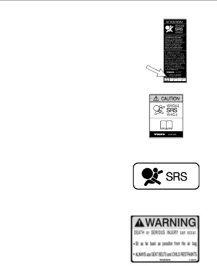
58 Additional Safety Features
Warning Labels
The label attached to the left hand sunvisor
shows the year and month when a Volvo
Truck dealer should be contacted for a
specific inspection and for a possible re-
placement of the airbag. This is done to
guarantee the function of the airbag after
the stated date. Replace the label when re-
placing the airbag module. Never attempt
to make any adjustments to SRS compo-
nents yourself. T8006843
Steering shafts and steering wheel should
not be removed, adjusted or replaced with-
out following the proper work procedure.
Failure to do so can damage the SRS sys-
tem to the point where it does not work any
longer. A warning label is located on the
upper steering shaft. T8006842
There is also a label on the inside of the
windshield that indicates the inclusion of
an airbag to the vehicle safety features.
T8006841
When equipped with an airbag, a label
about the correct procedure for protecting
small children and protecting the driver is
attached to the left hand, overhead storage
lid or back of sunvisor.
W8002741

Additional Safety Features 59
Any queries concerning the SRS system
should be directed to a Volvo Truck dealer.
There is no maintenance required for the
SRS system until the date stated on the
warning label located on the left hand sun-
visor.
Never attempt to repair any part of the
SRS system. Any interference with the
system may cause it to malfunction and
result in serious injury. Work on the sys-
tem may only be carried out by an
authorized Volvo Truck dealer.
To allow the SRS system to work as de-
signed:
•Never drive an SRS system equipped
vehicle with the hands on the steering
wheel pad/airbag module.
•No objects, accessory equipment or
stickers may be placed on, attached to
or installed near the SRS cover in the
center of the steering wheel.

60 Additional Safety Features
General Information
When is the airbag deployed?
The airbag is only deployed during a head-
on collision, where the vehicle hits a fixed
or heavy object with sufficient force. The
SRS system registers both the force of the
collision and the internal forces caused by
the collision. The control unit determines if
the collision is sufficiently violent for the
airbag to be deployed.
NOTE! The SRS system is only activated
once in a collision. If the airbag has de-
ployed, the following is recommended:
•Have the vehicle towed to a Volvo
Truck dealer. Even if the vehicle can
be driven after a collision, it is not
recommended to drive the truck
with the airbag deployed.
•Have an authorized Volvo Truck dealer
change the components in the SRS
system.
•Only use original Volvo parts when re-
placing the SRS system components
(airbag, safety belt, etc.).
When is the airbag not deployed?
Not all frontal collisions activate the SRS
system. In a collision with a soft object (a
snow drift or bush for example, or a hard
or fixed object at low speed), there is no
need for the SRS system to be activated.
The airbag is usually not inflated in re-
sponse to side-on collisions, impacts from
the rear or if the vehicle overturns. The ex-
tent of damage to the vehicle is no measure
of how well the SRS system works.

Additional Safety Features 61
Can the airbag be deployed acci-
dentally?
The complete SRS system is constructed so
that the airbag only inflates in particular
collision conditions. The SRS system has
its own diagnostic unit which continuously
monitors the functioning of the system.
Make a habit of checking the SRS system
telltale light when starting and driving the
vehicle.
Heart of the Volvo safety system
The three-point anchored safety belt is
the heart of the Volvo safety system. The
belt should be worn at all times. The SRS
system is intended as a supplement to the
three-point anchored safety belt.
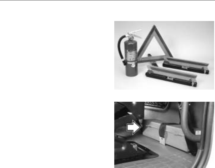
62 Additional Safety Features
Safety Equipment
Safety triangles and fire extinguishers are
available as optional equipment. The fire
extinguisher should be located by the base
of the driver seat, between the seat and the
door.
W1000071
Warning Triangles
The warning triangles are stored in a box
that is strapped to the back wall of the cab.
W0001372
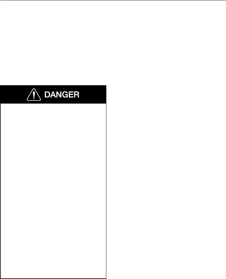
Additional Safety Features 63
VORAD Collision Warning System
The Eaton VORAD computerized Collision
Warning System constantly monitors vehi-
cles ahead with a front end mounted radar
and in a blind spot area with an optional
side mounted radar. The Collision Warning
System warns the driver of potentially dan-
gerous situations by activating visual and
audible alerts.
The Eaton VORAD Collision Warning
System is intended solely as an aid for
an alert and conscientious professional
driver. It is not to be used or relied upon
to operate the vehicle. Use this system
together with rear view mirrors and
other instrumentation to maintain safe
operation of the vehicle. Operate a VO-
RAD equipped vehicle in the same safe
manner as if VORAD was not installed.
The Eaton VORAD Collision Warning
System is not a substitute for safe driv-
ing procedures nor will it compensate
for any driver impairment, such as
drugs, alcohol or fatigue.
The Eaton VORAD Collision Warning
System may provide little or no warning
for some hazards like: alerts for pedes-
trians, animals, oncoming vehicles and
cross traffic. SmartCruise will not react
to stationary objects and it does not have
the capability to stop the vehicle.
Failure to follow these instructions may
lead to a crash resulting in severe per-
sonal injury or death.
If your vehicle is equipped with the Eaton
VORAD Collision Warning System, read
the manufacturer’s Driver Reference Man-
ual before taking the vehicle on the road.
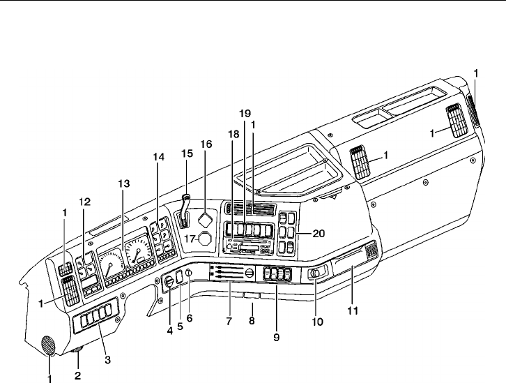
64 Instruments and Controls
Dash Overview
W8002383
1Air Vents ( page 176)
2Diagnostic Test Connection
3Left Switch Cluster ( page 94)
4Headlight Switch ( page 98)
5Driving/Fog Lights - option ( page 99)
6Instrument Light Dimmer ( page 107)
7Climate Unit Control Panel ( page 168)
8Hood Latch Handle ( page 26)
9Pneumatic Switches ( page 104)
10 Cigar Lighter ( page 107)
11 Ashtray
12 Instrument Cluster, Left ( page 68)
13 Instrument Cluster, Main ( page 76)
14 Instrument Cluster, Right ( page 83)
15 Trailer Hand Brake Control ( page 234)
16 Tractor Parking Brake ( page 229)
17 Trailer Air Supply ( page 229)
18 Radio - option ( page 188)
19 Optional Switches ( page 106)
20 Right Switch Cluster ( page 100)
Operating
Before driving this vehicle, locate the in-
struments and controls, and become
thoroughly familiar with their operation.
After starting and when driving, always
check that the instrument readings are
normal.
NOTE! Availability of gauges depends on
chosen options. All gauges and telltales
may not be used in all vehicles.
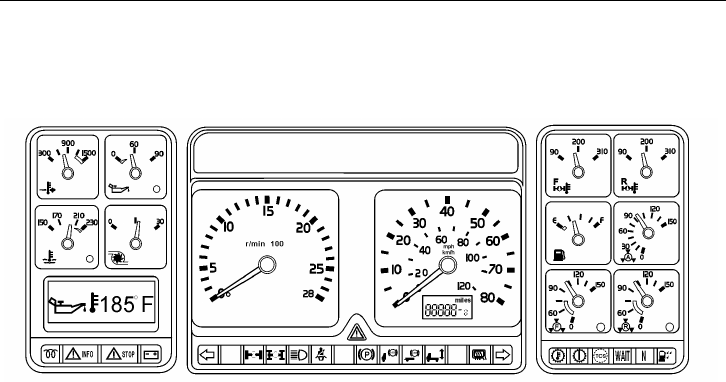
Instruments and Controls 65
Instrument Cluster Overview
W3004396
General
The cluster is available in seven different
configurations, with the speedometer either
graded in mph or km/h. The cluster con-
sists of three combined sections:
Left Section
The left section can include pyrometer, en-
gine oil pressure gauge, engine coolant
temperature gauge, turbo boost pressure
gauge and a graphic display for driver
information. See page 68 for gauge infor-
mation and page 108 for graphic display
information. There are telltales in the lower
part. Please refer to page 71 for telltale
information.
Center Section
The center section contains tachometer,
speedometer and odometer. See page 76 for
gauge information. In the lower part there
is a central warning lamp and telltales for
different vehicle functions. Please refer to
page 79 for telltale information.
Right Section
The right section can include forward and
rear axle temperature gauges, fuel level
gauge, application air pressure gauge, front
and rear brake air pressure gauges. Vehicles
with rear air suspension may have an air
suspension pressure gauge. See page 83 for
gauge information. There are telltales in the
lower part. Please refer to page 86 for tell-
tale information.
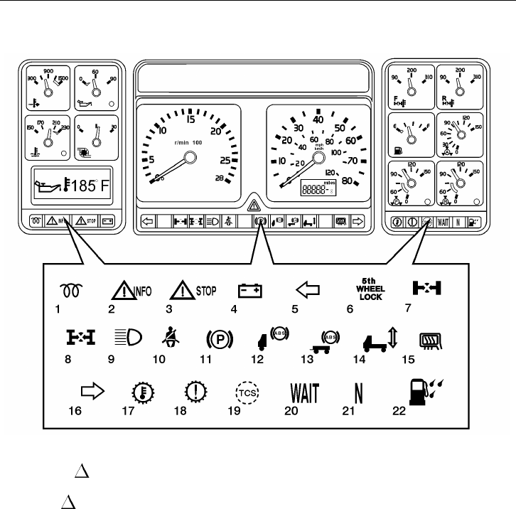
66 Instruments and Controls
Telltale Overview
W3004406
1Engine Preheat ( page 72)
2Yellow INFO Light
( page 73)
3Red STOP Light
( page 74)
4No Charge ( page 75)
5Left Turn ( page 80)
6Fifth Wheel Lock ( page 80)
7Wheel Differential Lock
( page 80)
8Axle Differential Lock
( page 80)
9High Beam ( page 81)
10 Safety Belt ( page 81)
11 Parking Brakes ( page 81)
12 Tractor ABS ( page 82)
13 Trailer ABS ( page 82)
14 Air Suspension Level
( page 82)
15 Mirror Heater ( page 82)
16 Right Turn ( page 80)
17 Transmission Temperature
( page 86)
18 Check Transmission
( page 86)
19 Traction Control System
( page 86)
20 Wait to Start (Not used)
21 Transmission in Neutral
( page 86)
22 Water in Fuel (Not used)
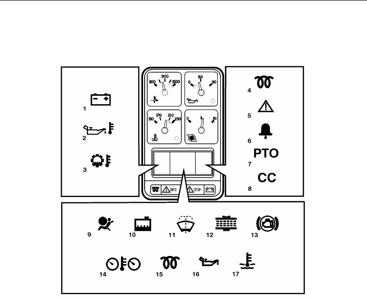
Instruments and Controls 67
Graphic Display Telltale Overview
W3003534
1Voltmeter ( page 156)
2Engine oil temperature ( page 153)
3Transmission oil temperature
( page 119)
4Preheating active ( page 72)
5Acknowledged warning ( page 124)
6Alarm clock on ( page 161)
7PTO engaged ( page 96)
8Cruise control engaged ( page 218)
9Airbag (SRS) ( page 57)
10 Coolant level ( page 120)
11 Washer fluid level ( page 114)
12 Engine airfilter clogged ( page 115)
13 Too cold for engine brake ( page 240)
14 Overheating, instrument cluster
( page 114)
15 Engine preheat fault ( page 202)
16 Engine oil pressure ( page 70)
17 Coolant temperature ( page 69)
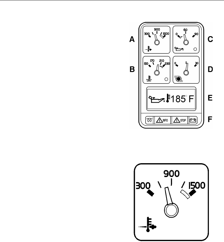
68 Instruments and Controls
Left Instrument Section
APyrometer (option) (this page)
BEngine Coolant Temperature
( page 69)
CEngine Oil Pressure ( page 70)
DTurbo Boost Pressure (option)
( page 71)
EGraphic Display ( page 108)
FTelltale Indicators ( page 71)
W3003644
A — Pyrometer (option)
An engine pyrometer system indicates the
exhaust temperature, which helps the opera-
tor get the best efficiency from the engine.
Variations in engine load can cause the ex-
haust temperature to vary. For example,
high exhaust gas temperature is the result
of prolonged engine lugging or overfueling.
If the pyrometer reading shows that exhaust
temperature exceeds normal, reduce fuel to
the engine until exhaust temperature is re-
duced. Shift to a lower gear if the engine is
overloaded. W3003632
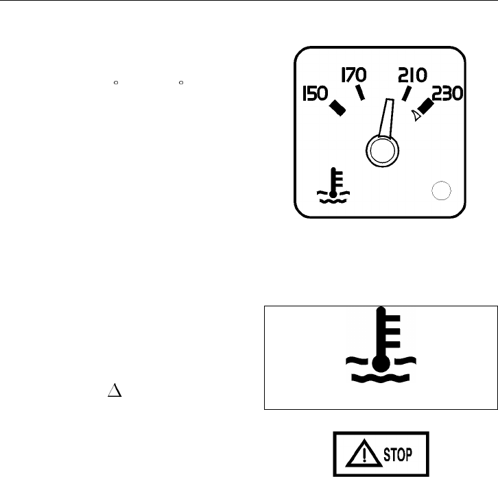
Instruments and Controls 69
B — Engine Coolant Temperature
The gauge indicates engine coolant temper-
ature. Normal operating temperature
reading is 165 to 205 F (75 to 95 C) for
the VOLVO engine. The temperature, under
normal driving conditions, must be below
the red sector. The temperature range for
the coolant will vary depending on the type
of engine, load, grade, ambient air tempera-
ture and operating conditions. If the
temperature remains below or exceeds the
normal temperature range, the cooling sys-
tem should be checked for problems by
your Volvo Truck dealer. W3003769
The LED light in the lower right corner of
the gauge lights up solid when coolant tem-
perature is excessive. The temperature limit
is dependent on the engine manufacturer
electronic program. Together with the
gauge light, the red STOP telltale will
come on and the buzzer will also sound.
The engine is at risk and the engine con-
troller may react by derating the engine
power. Stop at the first safe place where the
problem can be checked.
NOTE! If the coolant temperature returns
to normal shortly after exceeding the limit
and no repair has been made, the warning
messages go out but there will be a fault
message logged.
W3003614
T3008861
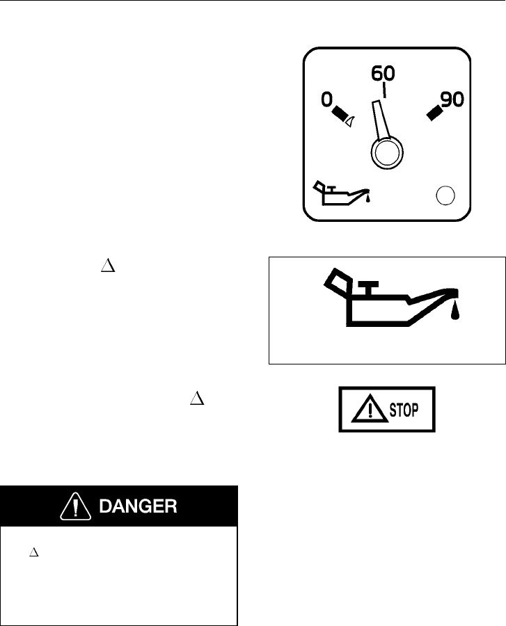
70 Instruments and Controls
C — Engine Oil Pressure
The gauge indicates oil pressure by a sensor
directly connected to the engine lubrication
system. Normal oil pressure is 30 to 70 psi
(210 to 480 kPa) when the engine is at nor-
mal operating temperature. At idle speed,
the pressure may drop to 5 to 20 psi (35 to
140 kPa). When first starting a cold engine,
oil pressure may exceed 90 psi (620 kPa).
The LED light in the lower right corner of
the gauge lights up solid when the oil pres-
sure is too low. The pressure limit is
dependent on the engine manufacturer elec-
tronic program. When the gauge light
comes on, the red STOP telltale starts
blinking, the buzzer sounds and the oil
pressure symbol appears on the graphic dis-
play. The engine is at risk and the engine
controller may react by derating the engine
power, for example. Bring the vehicle to a
safe stop where the problem can be
checked.
With very low oil pressure, the red STOP
telltale lights up solid. The engine will shut
down within 30 seconds from when the
light came on. Pull off the road as soon as
possible without being a safety hazard.
Failure to take necessary action when
the STOP telltale is on, can ultimately
result in automatic engine shutdown and
loss of power steering assist. Vehicle
crash resulting in personal injury or
death can occur.
W3003768
W3003613
T3008861
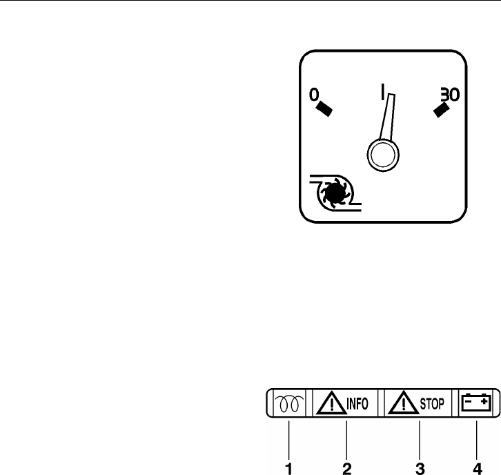
Instruments and Controls 71
D — Turbo Boost Pressure (option)
The gauge indicates intake manifold pres-
sure on the engine. The pressure is
generated by the turbo. Boost pressure
should be the same at a given engine tem-
perature, speed and load. Turbo boost
pressure will vary for different engines and
vehicle models. By monitoring the gauge,
the operator can avoid engine problems.
W3003631
F — Telltale Indicators, Left Section
1 Engine preheat telltale ( page 72)
2 Caution telltale ( page 73)
3 Stop telltale ( page 74)
4 No Charge telltale ( page 75) W3003645

72 Instruments and Controls
1 — Engine Preheat Telltale
The amber telltale will light when the in-
take manifold preheater is operating. The
heater is used for better cold starts. Opera-
tion time of the heater can vary in several
steps from 0 to 50 seconds depending on
coolant temperature and outside air temper-
ature. On cold mornings, the preheater will
be on for the maximum 50 seconds. When
the ignition key has been turned to the pre-
heat position, the preheater coils in the
intake manifold are activated to warm the
intake air. Once the engine is started, the
preheater may be re-engaged to assist in a
quicker engine warm-up. See page 202 for
information on using the preheater.
T3008841

Instruments and Controls 73
2— INFO Telltale
The yellow INFO telltale lights up to in-
dicate a control system or component
malfunction. In some cases, the engine
power may be derated (see page 114).
When the telltale comes on, stop at the first
safe place where the problem can be
checked.
When ignition is switched on, the telltale
goes out unless a defect is detected.
NOTE! On vehicles equipped with a Volvo
engine, the telltale is on for 3 to 5 seconds
after the ignition key switch is turned on.
See page 113 for a listing on related mes-
sages that trigger this telltale.
T3008860
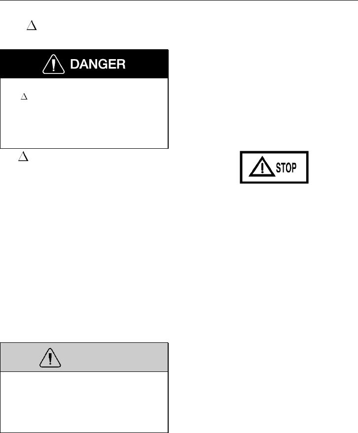
74 Instruments and Controls
3— STOP Telltale
Failure to take necessary action when
the STOP telltale is on, can ultimately
result in automatic engine shutdown and
loss of power steering assist. Vehicle
crash resulting in personal injury or
death can occur.
The STOP telltale lights up red to alert
the operator that a severe problem has been
detected and in some cases a preventive ac-
tion may be taken by the engine electronics
to protect the engine. For example: if oil
pressure or coolant level drops too low, the
engine will be forced to low idle and when
the vehicle speed is zero, the engine shuts
down. Another example is: with excessive
coolant temperature, the engine will gradu-
ally reduce power output to 50%. This
telltale always activates the buzzer.
The engine may be started again after the
key is turned off and then back on. How-
ever, it will only operate for 30 seconds
unless the problem is resolved.
WARNING
If the problem is allowed to persist, seri-
ous damage to the engine may occur.
Always repair the cause of the problem
before taking the vehicle into service
again.
The engine could be forced to low idle
within 30 seconds from when the light
came on. Pull off the road as soon as possi-
ble without being a safety hazard.
See page 120 for a listing on related mes-
sages that trigger this telltale.
T3008861

Instruments and Controls 75
4 — No Charge Telltale
The No Charge telltale lights up red when
a problem exists in the charging system or
when there is no output from the alternator,
such as when the engine is not running.
The No Charge telltale lights up dimly
when there are several volts difference be-
tween the system voltage and the alternator
output voltage. The telltale shines brighter
as the alternator output voltage drops.
For more information on the electrical sys-
tem, see page 245.
T3008832
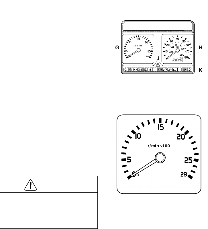
76 Instruments and Controls
Main Instrument Section
GTachometer ( this page)
HSpeedometer ( page 77)
JMaster Warning Telltale ( page 78)
KWarning Telltales ( page 79)
W3003643
G — Tachometer
The tachometer is electrically driven by a
signal from the engine. Monitor the
tachometer to guide correct gear shifting
and to prevent engine overspeeding when
descending steep grades. Each engine has
its ideal operating ranges for power and
economy. Read the engine manufacturer’s
manual to find out the best ranges for each
engine.
CAUTION
Always keep an eye on the tachometer
during downhill runs. Do not allow the
engine to over-speed. Excessive engine
over-speed can result in serious engine
damage.
W3003639
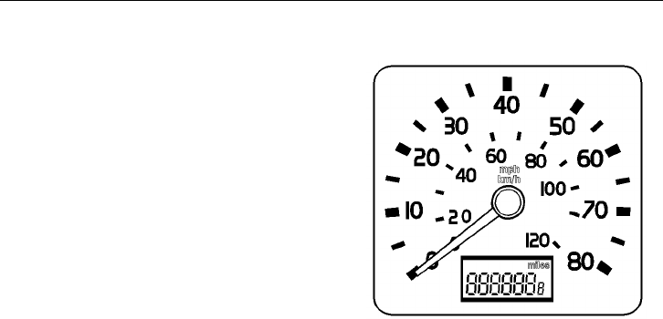
Instruments and Controls 77
H — Speedometer and Odometer
The speedometer is driven by the vehicle’s
electronic system. Recalibration of the
speedometer can be made to compensate
for tire size changes or other changes in the
vehicle driveline. This is done by repro-
gramming the engine or transmission
electronic controller. Reprogramming can
be performed by your authorized Volvo
Truck dealer.
The odometer is a Liquid Crystal Display
(LCD) mounted in the lower speedometer
face. The odometer registers up to
999,999.9 miles or km. The internal elec-
tronics will make distance conversions
between miles and km automatically.
To be able to read the current mileage
without turning the ignition on, press any
graphic display control to activate the
odometer and clock for approximately 30
seconds.
W3003640
78 Instruments and Controls
J — Master Warning Telltale
The Master Warning Telltale and buzzer
alerts of a dangerous situation. Air pres-
sure is low and the remaining air volume
may not be enough for repeated braking.
The emergency brakes may engage,
causing a wheel lock-up, loss of vehicle
control and become a hazard to follow-
ing vehicles. Bring the vehicle to a
controled stop. Failure to follow these
precautions can result in loss of braking
control and serious personal injury or
death can occur as a result of a vehicle
accident.
This will light up when either front or rear
air brake system pressure drops below 60
psi (410 kPa) or lower. The buzzer will
also sound when the telltale lights up.
When the pressure goes above 60 psi in
both front and rear brake circuits, the tell-
tale will automatically go out.
Air brake system pressure should be be-
tween 90 to 135 psi (620 to 930 kPa) for
normal operation. The master warning tell-
tale comes on and the buzzer sounds when
air pressure has dropped to 60 psi or lower.
If the air pressure is allowed to drop below
30 to 40 psi (200 to 275 kPa) in both
systems, the parking spring brakes will au-
tomatically engage and stop the vehicle.
When the master warning telltale comes on
and before the parking spring brakes en-
gage, stop the vehicle in a controlled
manner at an off-road location so as not to
be a hazard to other vehicles on the road.
Refer to page 224 for more information
about the brakes.
W3000638
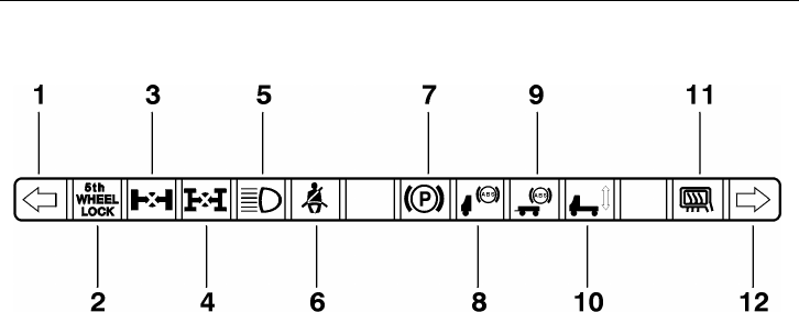
Instruments and Controls 79
K — Warning Telltales, Center Section
W3003646
1 Left Turn Telltale ( page 80)
2 Fifth Wheel Lock Telltale ( page 80)
3 Wheel Diff. Lock Telltale ( page 80)
4 Interaxle Diff. Lock Telltale ( page 80)
5 High Beam Telltale ( page 81)
6 Safety Belt Telltale ( page 81)
7 Parking Brake Telltale ( page 81)
8 Anti-Lock Brake System (Tractor or
Truck) Telltale ( page 82)
9 Anti-Lock Brake System (Trailer)
Telltale ( page 82)
10 Air Suspension System Telltale
( page 82)
11 Mirror Defroster Telltale ( page 82)
12 Right Turn Telltale ( page 80)
NOTE! All telltales may not be used in all
vehicles.
The telltale strip is located below the
tachometer and speedometer. A yellow cau-
tion telltale indicates that there is a system
or component in the vehicle that requires
the operator’s attention. A red warning tell-
tale indicates that there is a system or
component that should be checked before
the vehicle is driven any further.
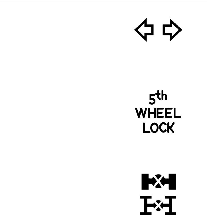
80 Instruments and Controls
Left and Right Turn Telltales
This lights up green when the turn signal is
activated and blinks in time with the out-
side turn signal lamps. An audible signal
also sounds in time with the telltale. A sin-
gle short beep is heard when the telltale
lights up.
W3000903
5th Wheel Lock Telltale
This telltale will light up yellow when the
pneumatic switch for the 5th wheel slide
lock is turned on. It will stay lit until the
switch is turned to the off position again.
See the 5th wheel uncoupling section on
page 280 for correct use.
W3000621
Wheel and Interaxle Differential Lock Telltales
These telltales will light up yellow when
the pneumatic switches for either the wheel
or interaxle differential lock are turned on.
For the interaxle lock, the telltale is acti-
vated by the switch. For the wheel lock, a
switch in the axle turns the telltale light on
only when the lock is actually engaged. It
turns the light off only when the lock is ac-
tually disengaged. See page 258 for proper
differential lock use.
W3000904
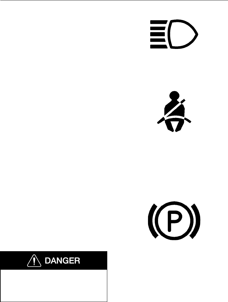
Instruments and Controls 81
High Beam Telltale
Any time the high beams are activated, by
the high/low beam switch or the high beam
flash switch, the telltale lights up blue. For
information on switching high/low beam,
see page 91. W3001303
Safety Belt Telltale
The telltale lights up red each time the ig-
nition is turned on to remind the driver to
fasten the safety belt. It stays lit for 10 sec-
onds and then goes out automatically.
Before adjusting the safety belt, make sure
the vehicle is stationary and that the seat
has been adjusted as required. Do not at-
tempt to adjust the safety belt or seat while
the vehicle is in motion. For proper use of
the safety belt, see page 48.
W3000625
Parking Brake Telltale
The telltale lights up red when the parking
brake valve knob is pulled out. The day-
time running light (DRL) function is also
dependent on the parking brake application.
Any time the parking brake telltale is on,
the DRL is deactivated.
Never exit your vehicle unless the park-
ing brake is set. Failure to do so can
result in unexpected vehicle movement
and cause personal injury or death.
For proper use of the parking brake, see
page 229.
W3000627
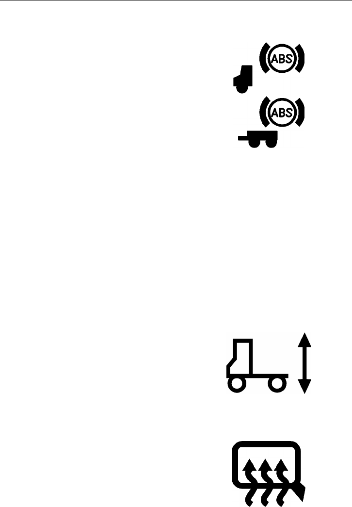
82 Instruments and Controls
ABS Telltale, Tractor and Trailer
The telltale lights up amber if the Anti-
Lock Brake System (ABS) senses a
problem under the following conditions:
1 The system will go through its self
test when the ignition switch is turned
on and the telltale should continue to
be on. The light should go out when
the vehicle speed reaches over approx-
imately 7 mph (11 km/h). If the
telltale stays on at higher speed, there
is a problem with the ABS.
2 The ABS telltale lights up during driv-
ing. The ABS self test has detected a
fault in the system.
The vehicle can still be driven with a prob-
lem in the ABS. However, the ABS will not
be operating and standard air braking is in
effect. For more information, see page 236.
The trailer ABS telltale is in effect for ve-
hicles manufactured after January 2000.
W3000905
Air Suspension Telltale
The telltale lights up amber when the sus-
pension leveling valve is activated. As long
as the switch is activated, the suspension is
lower than normal and the telltale is on. For
proper use of the suspension level control,
see fifth wheel uncoupling on page 276. W3002596
Mirror Defroster Telltale (option)
The telltale lights up amber when the mir-
ror defrost switch is engaged. Heater
temperature is automatically regulated by
an internal system in the mirror head.
W3000632
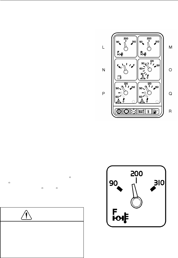
Instruments and Controls 83
Right Instrument Section
LForward Drive Axle Oil Temperature
(option) ( this page)
MRear Drive Axle Oil Temperature
(option) ( this page)
NFuel Level Gauge ( page 84)
OApplication Air Pressure (option)
( page 84)
OR
Air Suspension Pressure (option)
( page 84)
PFront Brake System Air Pressure
( page 85)
QRear Brake System Air Pressure
( page 85)
RWarning Telltales ( page 86)
W3004407
L & M — Forward & Rear Drive Axle Oil Temperature (option)
The gauges are connected to temperature
senders installed in the axles. Normal oper-
ating temperature range is up to 250 F
(120 C). If average oil temperature consis-
tently goes above 250 F (120 C), more
frequent oil changes are needed or an oil
cooler could be installed.
CAUTION
A sudden increase in oil temperature
that is not caused by a load increase
may indicate mechanical failure. Bring
the vehicle to a safe stop where the
problem can be checked. Do not operate
vehicle until correcting the problem.
W3003634
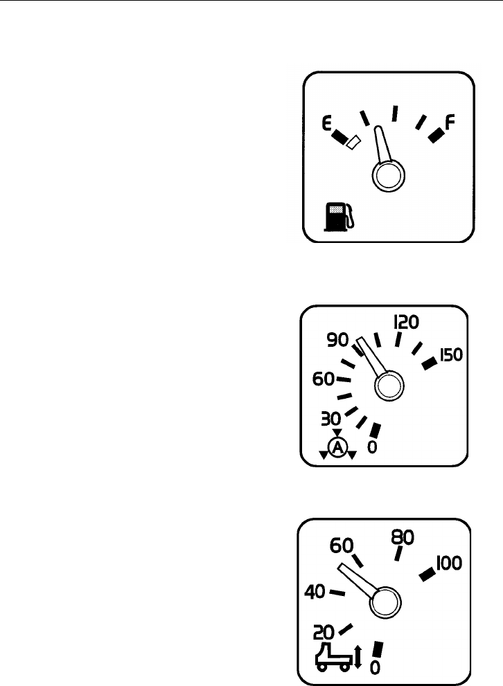
84 Instruments and Controls
N — Fuel Level Gauge
The gauge is connected to a sending unit in
the fuel tank. There is only one sender even
if the vehicle is equipped with dual tanks.
W3003628
O — Application Air Brake Pressure (option)
Air gauges are directly connected to the air
brake system. They will indicate the brake
application pressure from either the front,
rear or trailer circuit pressure.
The gauge will not register air pressure un-
til the foot brake pedal is depressed or the
trailer hand brake is applied.
W3004302
O — Air Suspension Pressure (option)
Air gauges are directly connected to the air
suspension system. It will indicate the sus-
pension pressure in the air springs.
The pressure shown on the gauge is a crude
indication of the load on the rear axle(s).
The gauge should not be used for trying to
balance the load between the axles.
W3003633
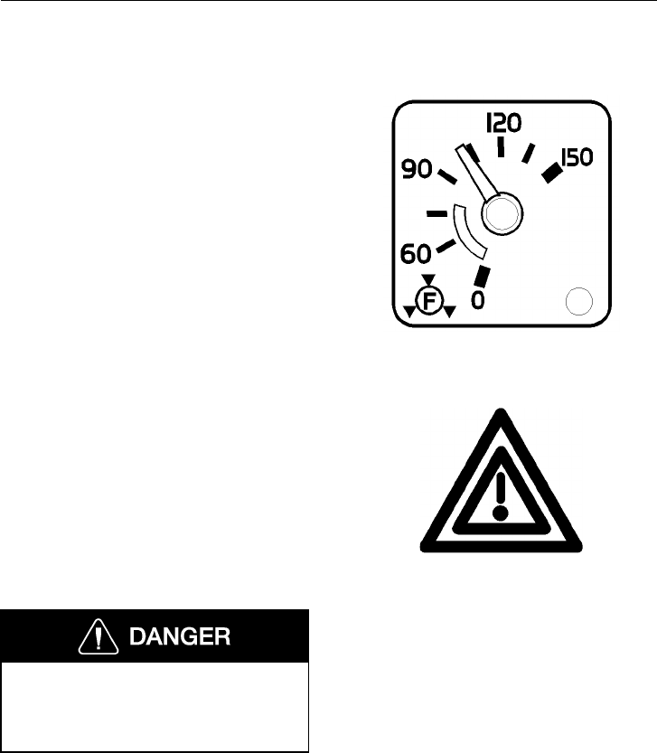
Instruments and Controls 85
P & Q — Front and Rear Brake System Air Pressures
The system air gauges are directly con-
nected to the front and rear circuit tanks.
The two gauges should register equal air
pressure. Air brake system pressure should
be between 90 to 135 psi (620 to 930 kPa)
for normal operation. The pointers in the
two gauges should register equal air pres-
sure. By observing the gauge pointers, the
operator can detect a pressure drop if an air
leak develops and can readily identify the
circuit affected. See page 224 for more in-
formation.
There is a low-air warning switch in each
gauge. If the pressure in a brake circuit air
tank drops below approximately 60 psi
(420 kPa), the red indicator in the lower
right corner of the gauge will light up and
the master warning indicator and the buzzer
will simultaneously come on. If the air
pressure is allowed to drop below 30 to 40
psi (205 to 275 kPa) in both systems, the
parking brakes will automatically engage to
stop the vehicle. Refer to page 224 for
more information about the brakes.
Failure to observe these precautions can
result in the loss of braking performance
and personal injury or death can occur
as a result of a vehicle crash.
W3003637
W3000638
Master Warning Indicator
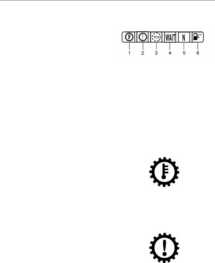
86 Instruments and Controls
R — Warning Telltales, Right Section
1Transmission Temperature (this page)
2Check Transmission (this page)
3Traction Control System ( page 87)
4Wait to Start (Not used)
5Automatic Neutral ( page 88)
6Water in Fuel (Not used)
W3004416
Transmission Temperature Telltale
The Transmission Temperature Telltale is
for the Allison WTEC III transmission. The
amber warning signal lights up and a
buzzer sounds when the transmission tem-
perature is too high. W3004305
Check Transmission Telltale
The Check Transmission Telltale is for the
Allison WTEC III transmission. The red
warning signal lights up to indicate a trans-
mission problem. Depending on the severity
of the problem, shifts may be restricted. W3004306
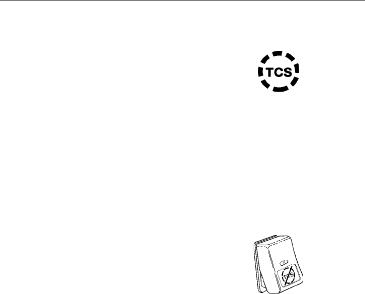
Instruments and Controls 87
Traction Control System Telltale
The amber telltale will blink only when the
Traction Control System (TCS) mud/snow
mode is engaged. At all other times, the
TCS system operates in the background
without indication. The system does not
have an on/off switch. See page 238 for
more information.
The TCS only operates at speeds lower
than 25 mph (40 km/h). The system detects
wheel spin by comparing wheel speeds and
controls the spin by using the brake system
to transfer power to wheels with greater
traction. Under circumstances where all
drive wheels are spinning, the system sends
a signal to the engine control unit to reduce
power.
W3000962
The TCS includes a TCS mud/snow switch
for turning the system off to increase wheel
spin. This function may be desirable in
deep snow or mud to keep the vehicle from
bogging down.
To operate, press in the bottom part of the
switch. The switch stays in this position
and the TCS telltale light blinks to indicate
that the mud/snow mode is engaged. To re-
turn to normal TCS operation, press the
bottom part of the switch again and it will
return to rest position.
W3001336
88 Instruments and Controls
Auto Neutral Telltale
The Auto Neutral Telltale is for the Allison
WTEC III transmission. The green indica-
tor lights up when the transmission is in
auto neutral. Auto neutral is activated just
before the vehicle comes to a complete stop
(less than 1.5 mph [2.5 km/h]). The gear is
re-engaged shortly (1–2 seconds) after the
brake pedal is released.
Allow for the gear re-engagement when ap-
plying throttle; do not increase engine
speed before the transmission has engaged.
If the engine speed is too high, the trans-
mission will not engage.
CAUTION
When operating the vehicle on normal
grades (less than 4%), a slight roll-back
can be experienced when the brake
pedal is released and before the trans-
mission re-engages.
NOTE! When operating on severe grades
(more than 5%), the transmission has a
safety feature that can be used. Before re-
leasing the brake pedal, manually press the
“DRIVE” key on the Allison gear selector,
and the gear is re-engaged manually to as-
sist in preventing roll-back.
W3004308
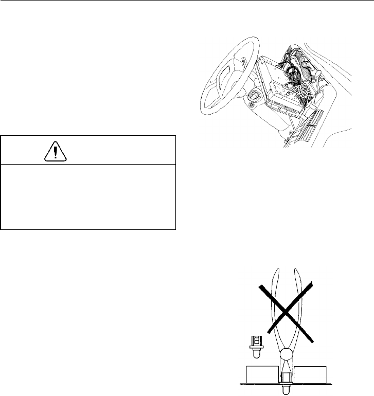
Instruments and Controls 89
Changing Telltale Bulbs In Cluster
NOTE! Before beginning to work, make
sure the vehicle ignition is switched OFF.
If possible, adjust the steering column
back. Remove the two screws at the top of
the instrument cluster and fold the cluster
out and let it rest face-down against the
steering column so the bulbs are accessible.
CAUTION
Do not let the cluster be in the
face-down position for more than maxi-
mum 15 minutes. Damage to the gauges
can occur by oil running out of them,
making the gauge reading inaccurate.
W3000842
Do not use any tools for changing the bulbs
other than the correct tool. Using a pair of
pliers could easily cause a short-circuit if
power is on, thereby destroying the circuit
board.
W3001306

90 Instruments and Controls
A bulb change tool is included with the
ignition keys on the keychain, or can be or-
dered from your Volvo Truck dealer under
part number 1089953. Use only this tool to
change bulbs in the instrument cluster.
To remove bulb, insert tool onto the bulb
assembly, rotate a 1/4 turn counterclock-
wise and pull the bulb assembly out of the
cluster.
Insert a new bulb into the tool and install it
into the cluster. Rotate the bulb a 1/4 turn
clockwise and pull the tool off of the bulb
assembly.
NOTE! The telltale area in the right part of
the instrument does not use all spaces for
active telltales. These bulbs can be used for
spare bulbs.
Lift up the instrument cluster and fasten the
two screws at the top of the cluster.
W3000642
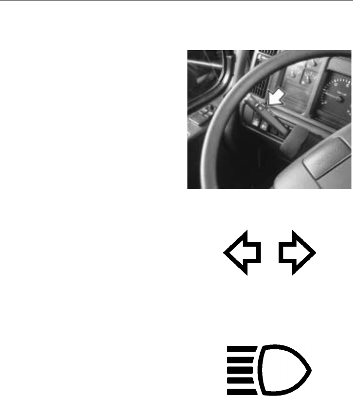
Instruments and Controls 91
Steering Column Switches
Turn Signal/Headlight Beam Change
The turn signal is activated by the lever un-
der the left side of the steering wheel. If
the vehicle is equipped with a cruise con-
trol, the controls for this are located on the
turn signal lever. See page 218 for more in-
formation about the cruise control.
The standard turn signal switch is not self
cancelling. It must be manually returned to
neutral position after making a turn. A self
cancelling turn signal is available as an op-
tion.
For lane changes, the lever does not need
to be moved to a locking position. Move
the lever partway off the normal position
until a resistance is felt. The turn signal is
now activated and the lever will return to
normal position when it is released.
The headlight flash function is activated by
pulling the turn signal lever toward the
steering wheel. The high beam will stay on
until the lever is released.
To change between high and low beam,
pull the lever all the way toward the steer-
ing wheel. When a slight clicking sound is
heard, release the lever.
NOTE! When switching from high to low
beam for oncoming traffic, release the lever
as soon as the beam change is made. Hold-
ing the lever up makes the headlight flash
function stay engaged.
W2002694
W3000903
W3001303
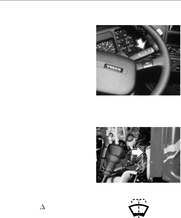
92 Instruments and Controls
Windshield Wiper/Washer
The wiper/washer functions are operated by
the same switch. The wipers have a normal
and a fast speed which are activated by
moving the lever down one or two posi-
tions. To let the wipers engage for one or
two passes, lightly depress the lever until
the wipers start and hold it there. The
wipers return to the parking position when
the lever is released.
The interval wiper function is engaged by
moving the lever up. The normal pro-
grammed speed is one pass every 10
seconds. To shorten the interval time, move
the lever to normal wipe position and then
to the interval position again when the next
wiper pass is desired. In this way, the inter-
val can be programmed between 1 to 10
seconds between each pass.
W3003655
To operate the windshield washer, pull the
lever toward the steering wheel. If washer
fluid needs to be added, use a commercially
reputable washer fluid that has good clean-
ing capability and does not freeze in cold
weather. Total reservoir capacity is 3.3 gal-
lons (12.5 liters).
W8000985
An indicator will appear on the graphic dis-
play and the yellow INFO telltale lights
up when there is approximately 1.4 gallons
(5.3 liters) remaining in the reservoir. A 10
second activation delay allows for fluid
slosh.
T3008838
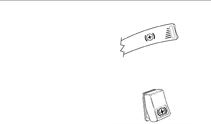
Instruments and Controls 93
Transmission Retarder
If the vehicle is equipped with an Allison
HD or MD transmission, the retarder lever
is located in front of the highbeam and
windshield wiper/washer lever. You can
move this lever to six different positions to
set the level.
The retarder on/off switch is located in the
dash, in the right-most position in the aux-
iliary panel. See page 243 for more
information.
W3004405
W3004428
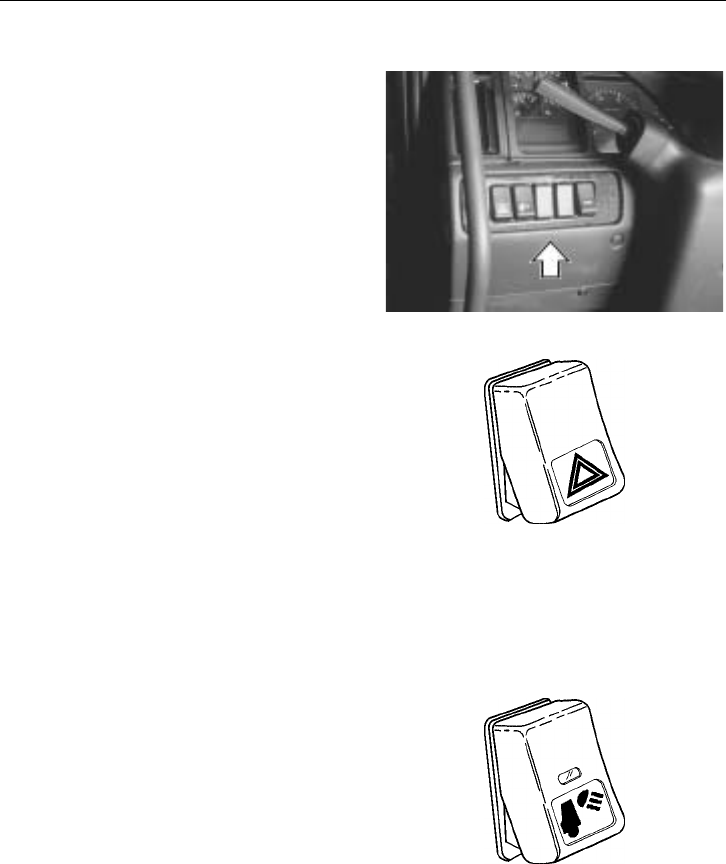
94 Instruments and Controls
Left Switch Cluster
This switch cluster has only one switch po-
sition permanently filled. Other positions
are for optional equipment. The standard
switch is for the Hazard Lights.
Other switches that can be located in this
cluster are for Back of Cab Light,
Headlight Flash, Power Take Off, Head-
light/Snowplow Changeover, and Fresh Air
Intake.
W3002002
Hazard Lights
The hazard or four-way warning circuit is
activated by pressing in the bottom part of
the switch. The indicator light in the switch
will flash in unison with the outside lights.
The hazard lights function independently
from the ignition switch.
Activate this function only when the vehi-
cle is stopped where it might be a danger
to other vehicles or to alert others of a
problem that changes the traffic rhythm.
W3001350
Back Of Cab Light (option)
Turn on the back of cab light by pressing
in the bottom part of the switch. The light
will stay on until the switch is returned to
off-position.
Back-of-cab lights are available as a flush-
mounted light in the middle of the cab rear
wall or as a high-mounted light on the side
of the cab. W3001355
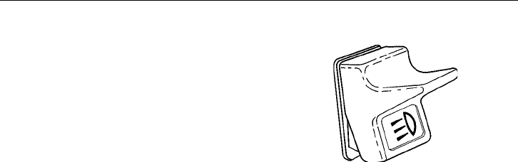
Instruments and Controls 95
Headlight Flash Switch (option)
The headlight flash switch will momentar-
ily turn the headlights off when pressed.
The switch will return when released, turn-
ing headlights on again. This switch
functions when either of Daytime Running
Lights or low beam headlights are on.
W3002306
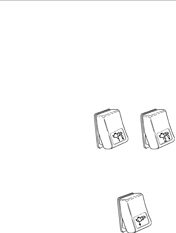
96 Instruments and Controls
Power Take Off
There are two basic types of PTOs avail-
able: engine mounted and transmission
mounted. The transmission mounted PTO is
clutch dependent, which means that opera-
tion can be regulated by depressing or
releasing the clutch pedal. This type of
PTO should not be in use while driving.
The engine mounted PTO is direct-mounted
to the engine and is engaged with a bypass
valve operated by the switch. This type of
PTO can be in use while driving.
Transmission Mounted PTO
The vehicle should be stopped before en-
gaging power take off. Engage the PTO by
depressing the clutch pedal and pressing in
the bottom part of the switch. Release the
clutch pedal to start the PTO.
One or two PTOs can be run at the same
time. Applications change depending on
customer needs and components.
W3001994
Engine Mounted PTO
The engine should be running at low idle
and the vehicle should be stopped or run-
ning at very low speed before engaging
power take off. Engage the PTO by press-
ing in the bottom part of the switch. The
PTO is now in operation and hydraulic flow
can be regulated by the engine speed. W3001993
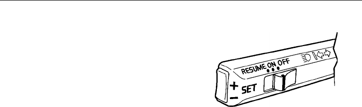
Instruments and Controls 97
PTO Speed Adjustment
Have the PTO engaged before adjusting the
speed. For the PTO speed adjustment to
function, the Cruise Control or idle adjust
can not be active, brake and clutch pedals
must be released, and vehicle speed must
be under approximately 5 mph (8 km/h).
To set engine speed:
1 Set the PTO/CC switch in the ON po-
sition.
2 Use the accelerator to increase engine
speed.
3 Momentarily press the SET+ or SET-
switch to set current engine speed.
To increase/decrease engine speed:
1 Press and release the SET+ or SET-
toggle switch to increase/decrease
speed in increments (increment size
depend on programmed value).
2 Press and hold the SET+ or SET- tog-
gle switch to increase/decrease speed.
When the switch is released, the en-
gine speed sets at current speed.
To resume engine speed:
1 If the PTO function was interrupted,
resume set speed by pressing the
PTO/CC switch to RESUME and re-
leasing.
To deactivate PTO speed function:
1 Set the PTO/CC switch to the OFF po-
sition.
2 Press down the service brake pedal.
3 Depress the clutch pedal.
4 Increase vehicle speed above PTO
working range (typically 5 mph [8
km/h]).
W3002499
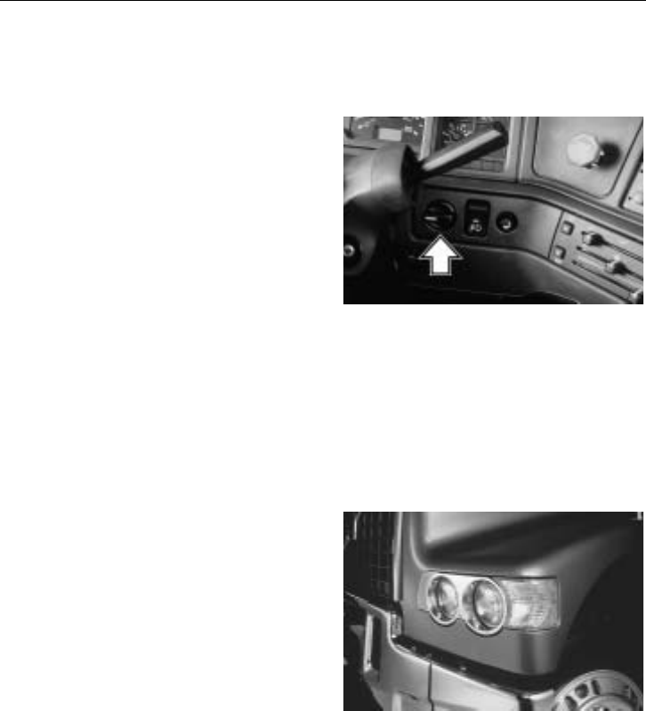
98 Instruments and Controls
Driving Light Switches
Headlights
The headlight switch controls parking lights
and headlights. It is a two position rotary
switch, turning on parking lights, cab
marker lamps and taillights in the first posi-
tion and turning on headlights in the
second position.
To change between high and low beam,
pull the direction indicator lever all the way
toward the steering wheel. When a slight
clicking sound is heard, release the lever.
NOTE! When switching from high to low
beam for oncoming traffic, release the lever
as soon as the beam change is made. Hold-
ing the lever up makes the headlight flash
function stay engaged.
W3000955
The headlight unit consists of four sealed
beam inserts. The two outer lights are low
and high beam, and the inner lights are
high beam only. If the headlight burns out,
change the whole insert.
Daytime Running Lights (DRL) are stan-
dard. They are automatically switched on
when the parking brakes are released (igni-
tion must be on) and will stay on until the
parking brakes are engaged.
NOTE! Do not use DRL at night or at any
time visibility is reduced. DRL is not a
substitute for the main vehicle lights when
driving at night.
W3004425

Instruments and Controls 99
Driving and Fog Lights (option)
Combinations of driving and fog lights can
be mounted in standard locations in the
aerodynamic bumper or from the underside
of the steel bumper. These are operated by
a switch next to the headlight switch.
Fog and driving lights are wired so they are
turned on only when the headlight switch is
on. Fog lights are used with the parking
lights and the low beam headlights. Driving
lights are used with the high beam head-
lights. Switching from low to high beam
will automatically switch from fog lights to
driving lights.
Driving and fog lights should be used when
driving conditions require additional light-
ing. The driving or fog lights should not be
used in traffic where they might distract
other drivers thereby creating a safety haz-
ard.
If the fog/driving lights are added to the ve-
hicle as an accessory later on, make sure the
light controls are wired as described above.
W3001356
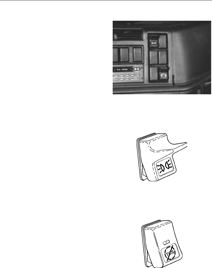
100 Instruments and Controls
Right Switch Cluster
This switch cluster can hold up to six
optional equipment switches. Planned func-
tions are Marker Interrupt, Traction Control
(TCS), Exhaust or Engine Brake and
Heated Mirrors.
W3000972
Marker Interrupt Switch
The switch interrupts power to the marker
lights when held down. When released, it
will spring back to the ON position and re-
turn power to the marker lights.
W3001352
Traction Control Switch
If the vehicle is equipped with a Traction
Control System (TCS), there is a switch
that can be used for increasing wheel spin.
This may be useful for decreasing the
chances of getting bogged down when
driving in heavy snow, slush or muddy con-
ditions. See page 238 for more information.
W3001336
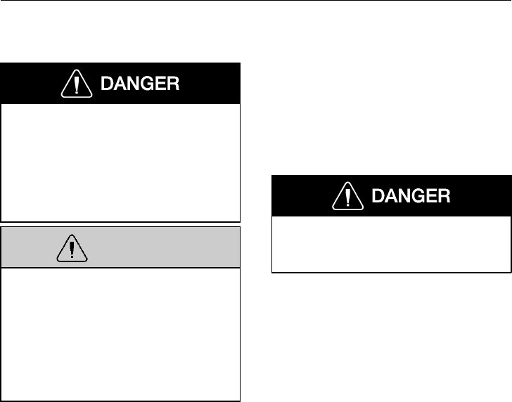
Instruments and Controls 101
Exhaust/Engine Brake
When operating your tractor bob-tail
without a trailer or on slippery roads,
the engine brake switch must be in the
“OFF” position. Failure to follow these
instructions can result in loss of vehicle
control and serious personal injury or
death may occur.
WARNING
A vehicle speed retardation device (such
as “Jake Brake,” “C-Brake,” “Exhaust
Brake,” etc.) is not intended to replace
the service brake system on your vehicle
nor intended to bring your vehicle to a
stop. A vehicle speed retardation device
is only intended to retard the speed of
your vehicle under certain conditions.
NOTE! It is normal for there to be a slight
delay in the application of a vehicle speed
retardation device. When using a device of
this type, be sure to think ahead and ana-
lyze conditions in order to use the device
properly.
Failure to observe these precautions can
result in loss of vehicle control and seri-
ous personal injury or death can occur.
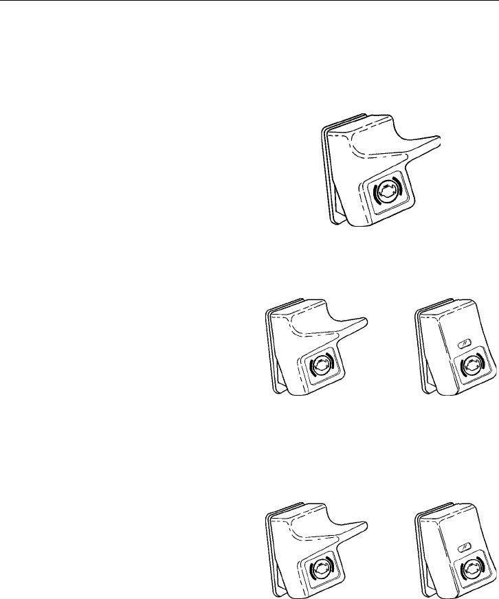
102 Instruments and Controls
Several types of engine brakes can be in-
stalled or are standard on certain engines.
All are used to reduce wear on the vehicle
brake linings.
Exhaust Brake, Volvo Engine
The exhaust brake is standard equipment on
the Volvo engine. It provides braking effect
to the rear wheels by trapping the exhaust
in the engine. The switch for exhaust brake
has two positions: ON and OFF.
The exhaust brake is most effective at high
engine speed (1 500 to 2 300 r/min). For
proper operation, see page 240.
W3001324
Engine Brake, Volvo Engine — Optional
The Volvo Engine Brake (VEB) is a com-
pression brake. It works together with the
exhaust brake to provide two levels of
braking power. The switch has three posi-
tions: OFF, LOW and HIGH. With the
switch in position LOW, only the exhaust
brake is engaged. With the switch in posi-
tion HIGH, both the exhaust brake and
compression brake are activated. For proper
operation, see page 241.
W3002303
Jake Brake or C–Brake — Optional
These engine brakes are similar in opera-
tion and are compression brakes. Three
power levels are available by engaging 2, 4,
or 6 cylinders in the braking (for Cummins
M11, only two power levels are available).
The left of the two switches is the ON/OFF
switch. The right switch is for selecting the
amount of braking power with positions
LOW, MED. and HIGH (for Cummins
M11, only LOW and HIGH). For proper
operation, see page 242.
W3002303
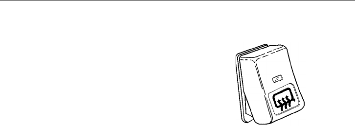
Instruments and Controls 103
Heated Mirror Switch (option)
The vehicle can be equipped with heated
mirrors. The switch turns on an electric
heater element that is a part of the mirror
glass. The heater is self regulating and will
keep a steady temperature after reaching
operating temperature. Both top and bottom
mirrors are heated.
Turning the switch on activates a telltale in
the instrument cluster. The telltale will stay
on until the switch is turned off.
W3003492
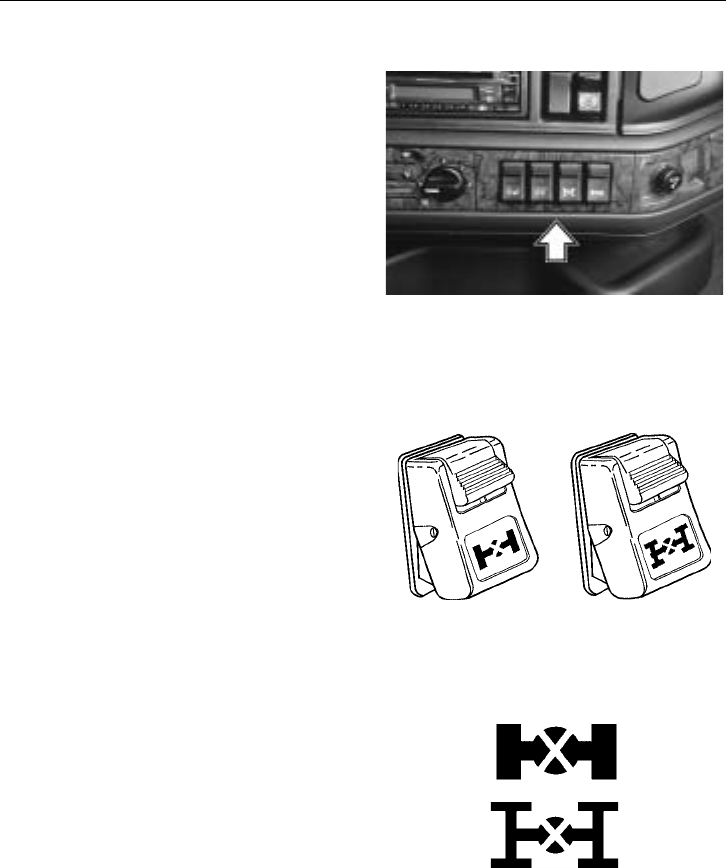
104 Instruments and Controls
Pneumatic Switch Cluster
The pneumatic switch cluster can have up
to four optional equipment switches. They
regulate air flow directly to the following
equipment: Differential Lock — Wheel and
Interaxle, Air Suspension Level and Fifth
Wheel Slide.
To prevent accidental engagement, each
switch has a latch that needs to be pressed
down before the switch can be operated.
W3002003
Differential Locks (option)
There are differential locks available for
each driving axle (4X2 or 6X4) or between
axles on a 6X4. The differential lock elimi-
nates one-wheel spin-out on slippery
surfaces and improves traction. Each switch
has a safety latch to prevent accidental en-
gagement. When the lock is engaged, a
telltale lights up in the instrument cluster.
A differential lock should only be used on
a slippery surface and not when driving on
good road conditions. If a differential lock
telltale is activated in the instrument clus-
ter, do not make turns until the telltale has
gone out. See page 258 for information on
how to properly engage and drive with dif-
ferential locks engaged.
W3001991
Left: Wheel diff. lock
Right: Inter-axle diff. lock
W3000904
Telltales
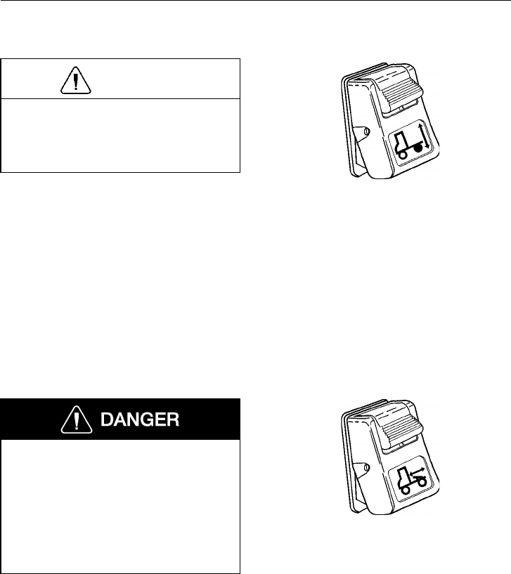
Instruments and Controls 105
Suspension Level
CAUTION
The vehicle must never be driven with
the air springs deflated. Damage to air
suspension parts will occur if springs are
not inflated properly.
Tractors with rear air suspension have a
control for deflating the air springs. Use this
when uncoupling from trailers. See page
276 for correct operation when uncoupling.
The switch has a safety latch to prevent ac-
cidental engagement. Depress the latch and
press in the bottom part of the switch to
deflate the air springs. A telltale in the in-
strument cluster will light up when the
switch is in the “on” position.
W3001341
Sliding Fifth Wheel
The release must never be operated
while the vehicle is operating on the
road. Fifth wheel position adjustment
must only be done when stationary.
Damage to the fifth wheel, trailer king-
pin and slider may occur if not operated
properly and may lead to an accident,
causing serious personal injury or death.
Tractors with a sliding fifth wheel mount-
ing have an air operated release as standard
equipment. The sliding fifth wheel is used
for distributing loads more favorably be-
tween the front and rear axles to comply
with varying state and provincial laws. See
page 280 for correct operation.
Depress the latch and press in the bottom
part of the switch to release the slider locks.
W3001346
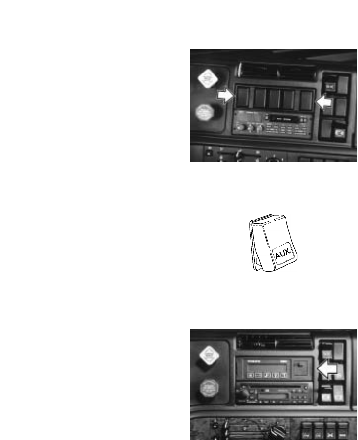
106 Instruments and Controls
Optional Switch Cluster
The optional switch cluster can either be
used for additional switches when the other
clusters are used up or can be removed to
house more radio equipment. The opening
is a standard DIN radio slot.
W3000973
Generic switches are available for auxiliary
functions that are installed by the customer.
These should be located in the optional
switch cluster and can be purchased from
your local Volvo Truck dealer.
W3002419
Optional switches such as an Eaton Vorad
display, Eaton Autoshift display or Allison
Transmission Retarder can be installed, or
the optional switch panel can be removed
and a radio or Volvo Road Relay can be
installed.
W3002420
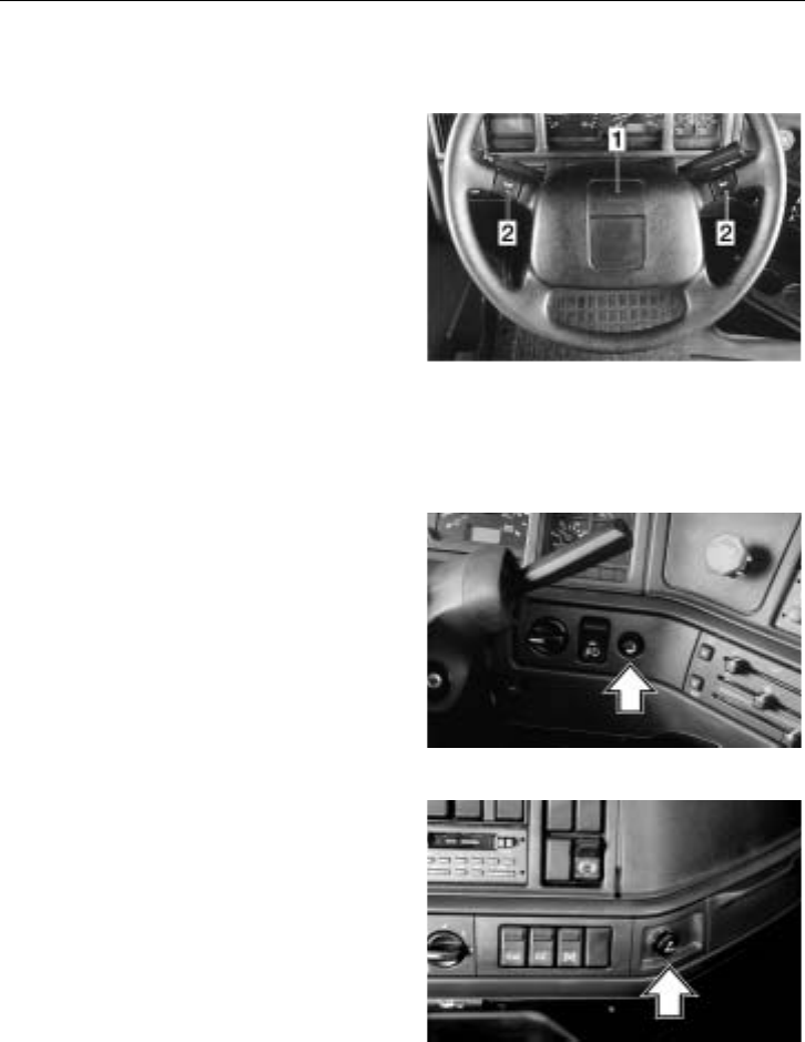
Instruments and Controls 107
Miscellaneous Switches
Horn Switches
Electric and air horns are standard equip-
ment. They are both operated from the
steering wheel. The air horn button (1) is
located in the middle of the steering wheel.
If the vehicle is equipped with an airbag
(SRS), the airbag module can be pressed
down anywhere around the edge to engage
the air horn.
There are two buttons for the electric city
horn (2) located on the steering wheel
spokes. W8000947
Instrument Light Dimmer Switch
The switch is a rheostat that controls the
instrument light. Instrument light is
activated by the headlight switch. Light in-
tensity can be varied from off to full
brightness by turning the rheostat clockwise
or counterclockwise.
W3000956
Cigar Lighter
To operate the cigar lighter, press in the
center until it stays in. The heater element
will heat up and pop the lighter out when it
is ready for use.
The ash tray is located next to the cigar
lighter.
W3000959
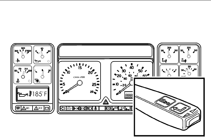
108 Graphic Display
Graphic Display Overview
T3010426
The display in the bottom left-hand corner
of the instrument cluster presents opera-
tional information to the driver. The display
menus and functions are selected with the
controls on the right-hand side of the steer-
ing wheel. Certain information will be
shown automatically (e.g. warning mes-
sages that need immediate attention).
The display has a large number of main
menus and sub-menus used for selecting
the correct functions. This section describes
each function: how the display functions
are accessed with the controls on the wind-
shield wiper lever and which actions are
required by the driver when messages are
automatically shown in the display.
The information which is accessible varies,
depending on whether the truck is in a
driving or non-driving mode. Certain func-
tions are protected by a password and are
not shown until the correct password has
been entered. Password protected functions
are described in Service Manual
“Instrumentation, VN, from 3/99 and VHD”
(see page 287 for order information).
In order to control a specific function it is
important to know which menu you are
working in. When a function is described
in this section, the information contains the
menu name. For example:
”MENU:” Set-Up Mode, Language.
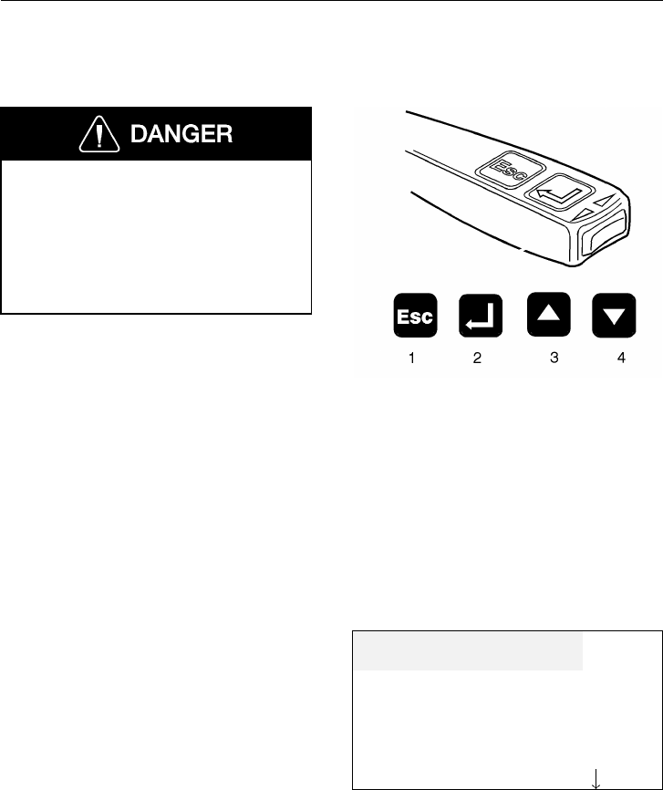
Graphic Display 109
Graphic Display Controls
If the vehicle is in motion, use the dis-
play controls carefully. Do not lose road
concentration. Be familiar with operation
of the controls. Shifting concentration to
operating the controls can lead to losing
control of the vehicle and may result in
serious personal injury or death.
The controls for the graphic display are lo-
cated on the windshield wiper lever on the
right-hand side of the steering wheel. The
following commands are available:
1 “Esc” is used to return to the previous
menu and cancel a setting/operation.
2 “Select” confirms a highlighted selec-
tion of a menu or character.
3 “Up arrow” moves the cursor up. Used
when setting numerical values.
4 “Down arrow” moves the cursor down.
Used when setting numerical values.
T3008810
Selecting a Menu
1 Using the up/down buttons the cursor
is moved to the particular menu,
which is then highlighted. A down ar-
row in the lower right-hand corner
shows whether there are any more
menus available. If this is the case,
you can continue to step down through
the list (see the adjacent example).
2 Pressing SELECT confirms the choice.
3 Pressing Esc exits the chosen menu.
By pressing Esc repeatedly, the cursor
is moved successively back to the
main menus.
Set-up mode
System diagnostic
Data log mode
Password Input

110 Graphic Display
Changing Settings
1 The up/down buttons increase or re-
duce the set values (e.g. hours and
minutes in the adjacent example).
2 Pressing SELECT confirms the choice.
3 If there are several settings to change
in the same menu, the cursor is moved
to the next setting using the up/down
buttons (e.g. the selection between
ON, OFF and SET in the adjacent ex-
ample).
4 Esc moves the highlight to the previ-
ous number or selection, if there are
any, otherwise the setting is cancelled.
ALARM 08:20
CLOCK 08:00
ON OFF SET
Display Menus
There are a number of main menus, each
with sub-menus, that lists functions avail-
able. There are two types of menus: Those
that are available when the vehicle is in
motion and those that can only be accessed
when stationary. Several non-driving sub-
menus are only accessible with a password.
The password-protected menus are not cov-
ered in this manual (see page 152).
While the vehicle is stationary, there are 4
menus in addition to the 4 drive menus.
Also, the menu TIME/DISTANCE has one
additional function while the vehicle is
stationary.
Non-Driving Mode Menus
•Set-Up Mode
(see page 126)
•System Diagnostic
(see page 131)
•Data Log Mode
(see page 146)
•Password Input
(see page 152)
Driving Mode Menus
•GAUGE
(see page 153)
•FUEL ECONOMY (option)
(see page 157)
•TIME/DIST
(see page 159)
•FAULTS?
(see page 164)

Graphic Display 111
Graphic Display Telltales
W3003534
1Voltmeter ( page 156)
2Engine oil temperature ( page 153)
3Transmission oil temperature
( page 119)
4Preheating active ( page 72)
5Acknowledged warning ( page 124)
6Alarm clock on ( page 161)
7PTO engaged ( page 96)
8Cruise control engaged ( page 218)
9Airbag (SRS) ( page 57)
10 Coolant level ( page 120)
11 Washer fluid level ( page 114)
12 Engine airfilter clogged ( page 115)
13 Too cold for engine brake ( page 240)
14 Overheating, instrument cluster
( page 114)
15 Engine preheat fault ( page 202)
16 Engine oil pressure ( page 70)
17 Coolant temperature ( page 69)
112 Graphic Display
Information and Stop Messages
The information and stop messages work
together with the INFO or STOP tell-
tales below the Graphic Display. If the
engine is running, the buzzer will sound at
any time the STOP telltale comes on.
Information Telltale
NOTE! When the yellow INFO telltale
lights up, the indicated fault should be
checked at the next stop.
See page 113 for a listing of other telltales
that are linked to the INFO telltale.
T3008860
Stop Telltale
Failure to take necessary action when
the STOP telltale is on, can ultimately
result in automatic engine shutdown and
loss of power steering assist. Vehicle
crash resulting in personal injury or
death can occur. Bring the vehicle to a
safe stop where the problem can be
checked.
See page 120 for a listing of other telltales
that are linked to the STOP telltale.
T3008861
More than one message can be active at the
same time. When a new message is acti-
vated, the new one is shown instead of the
old. A downward pointing arrow in the
right-hand corner of the display means that
several messages are active.
Graphic Display 113
Information Telltale
General
The yellow INFO telltale lights up when
an abnormal status is detected by an elec-
tronic control unit. A telltale or text, or
both, are shown in the display in addition
to the INFO telltale. For certain telltales,
a reference value is also shown.
The telltales are described starting on page
114, text messages are described starting on
page 117 and combined telltale and text
messages are described starting on page
119.
Important! When this telltale lights up, the
indicated fault should be checked at the
next stop.
T3008860
Information messages can be put on
standby if other information needs to be ac-
cessed on the display. See page 124 for
information on how to acknowledge mes-
sages and how to recall messages.
114 Graphic Display
Telltales
The yellow INFO lights up and a telltale
is shown in the graphic display, describing
in what component the problem has
occurred:
Airbag
The airbag (SRS) is described on page 57.
CAUTION
The vehicle should be taken to an autho-
rized Volvo Truck dealer immediately if
the SRS telltale stays on or lights up
when the vehicle is being driven.
T3008842
Instrument Cluster Overheating
The symbol is shown when the temperature
behind the instrument cluster is too high.
The instrument lighting becomes weaker
and the indicators on the instrument show a
minimal reading. Lower the heat in the
cab! When the heat is reduced, the instru-
ment functions will gradually be restored.
NOTE! If the temperature is too high over
a prolonged period, the instrument cluster
can be damaged.
T3008840
Washer Fluid Level
The telltale lights when there is approxi-
mately 1.4 US gallons (5.3 liters) of fluid
remaining in the reservoir.
T3008838
Graphic Display 115
Air Filter Blocked (option)
When the telltale lights, the engine air filter
is blocked. A blocked filter will cause
higher fuel consumption and black smoke.
To replace air filter, see the Operator’s
Manual, Maintenance and Engine.
T3008843
Too Cold for Engine Brake (Volvo Engine Only)
Position 2 of the engine brake should not
be switched on until the engine has become
warm (over 110 F [45 C]). If position 2 is
selected and the engine is too cold, this
symbol will be shown (however, VEB is
not activated).
T3009355
Fault in Preheating
See page 202 for more information on the
Volvo engine preheater.
T3008841
116 Graphic Display
Transmission Oil Temperature
This telltale lights when the transmission
oil temperature is too high. It is shown with
a text information about the temperature.
See page 119 for more information. T3008831
Charging System
This telltale lights when there is a problem
in the charging system. It is shown with
text information of the charging system sta-
tus. The voltage is shown together with the
message TOO HIGH. See page 156 for
more information.
T3008832
Engine Oil Temperature
This telltale lights if the engine oil temper-
ature becomes too high. It is shown with
the text TOO HIGH. The engine power is
derated. The temperature limit for activa-
tion varies for different engines. See page
153 for more information.
T3008830
Graphic Display 117
Text
The yellow INFO telltale lights up and
information text is shown on the display.
The text contains information on where the
fault has occurred as well as the type of
fault (applies to the data link):
Factory installed equipment:
CHECK
ENGINE
NEXT STOP
T3008860
Specific data link fault:
CHECK
ENGINE
DATA LINK
T3008860
118 Graphic Display
Data link broken:
CHECK
DATA LINK
BROKEN
T3008860
Not factory installed equipment:
The following can be shown if equipment
has been added by a customer and con-
nected to the data link:
MID (Message IDentifier) = controller
To find more information on the data link
diagnostic function, see page 131.
CHECK
ERROR IN
MID 142
T3008860
Graphic Display 119
Telltale + Text
The yellow INFO telltale lights up and
information text together with a value is
shown on the display. The text contains in-
formation on where the fault has occurred
and the value will show how much above or
below the limit the current conditions are:
Transmission Oil Temperature
If the transmission oil temperature becomes
too high, the INFO telltale lights up
automatically with the text HIGH. This tell-
tale and text will come on when the oil
temperature has been 210 F (100 C) or
above for 30 minutes or 250 F (120 C) or
above for 10 minutes.
NOTE! If the temperature goes over 285 F
(140 C), a STOP message will be gener-
ated; see page 123.
T3008831 HIGH
225 F
T3008860
Voltmeter
The voltmeter value, including the text
TOO HIGH, is automatically shown if the
charging system voltage becomes too high.
T3008832 TOO HIGH
17 V
T3008860
120 Graphic Display
Stop Telltale
In the event of a serious fault, the red
STOP telltale lights up and the buzzer
sounds (if the engine is on). In addition to
the STOP telltale, a symbol or text, or
both, are shown in the display. A reference
value is also shown for certain telltales.
T3008861
Telltales
Coolant Level
Failure to take necessary action when
the STOP telltale is on, can ultimately
result in automatic engine shutdown and
loss of power steering assist. Vehicle
crash resulting in personal injury or
death can occur. Bring the vehicle to a
safe stop where the problem can be
checked.
The telltale is shown if the coolant level is
too low. During check Pre–trip (option) a
text message is shown if the level is too
low.
T3008851
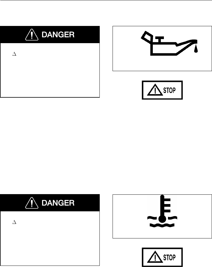
Graphic Display 121
Engine Oil Pressure
Failure to take necessary action when
the STOP telltale is on, can ultimately
result in automatic engine shutdown and
loss of power steering assist. Vehicle
crash resulting in personal injury or
death can occur. Bring the vehicle to a
safe stop where the problem can be
checked.
This symbol is shown when the engine oil
pressure is too low. The LED in the gauge
lights up together with the telltale and the
buzzer also sounds. Depending on the en-
gine manufacturer’s program in the ECU,
the trip point may differ slightly for differ-
ent engines.
W3003613
T3008861
Coolant Temperature
Failure to take necessary action when
the STOP telltale is on can ultimately
result in automatic engine shutdown and
loss of power steering assist. Vehicle
crash resulting in personal injury or
death can occur. Bring the vehicle to a
safe stop where the problem can be
checked.
The symbol is shown when the coolant
temperature is too high.
W3003614
T3008861
122 Graphic Display
Text
The red STOP telltale lights up and in-
formation text flashes on the display. The
buzzer sounds if the engine is running. The
text includes information about where the
fault has occurred:
Failure to take necessary action when
the STOP telltale is on, can ultimately
result in automatic engine shutdown and
loss of power steering assist. Vehicle
crash resulting in personal injury or
death can occur. Bring the vehicle to a
safe stop where the problem can be
checked.
Specific data link fault:
STOP!
DATA LINK
BRAKES
Factory fitted equipment:
STOP!
ENGINE
FAILURE
Not factory fitted equipment:
The following is shown if the customer has
fitted equipment which is connected to the
data link:
MID (Message IDentifier) = controller.
To find more information on the data link
diagnostic function, see page 131.
STOP!
FAILURE IN
MID 142
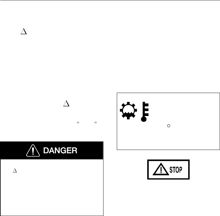
Graphic Display 123
Telltale + Text
The red STOP telltale lights up and in-
formation text together with a value is
shown on the display. The text contains in-
formation on where the fault has occurred
and the value will show how much above or
below the limit the current conditions are:
Warning, temperature transmission oil
If the temperature of the transmission oil
becomes too high, the red STOP telltale
is shown automatically with the text TOO
HIGH. This warning will come on when
the oil temperature has been 285 F (140 C)
or above for over 30 seconds.
Failure to take necessary action when
the STOP telltale is on, can ultimately
result in automatic engine shutdown and
loss of power steering assist. Vehicle
crash resulting in personal injury or
death can occur. Bring the vehicle to a
safe stop where the problem can be
checked.
T3008831 TOO HIGH
285 F
T3008861
124 Graphic Display
Acknowledge Information and Stop Messages
By pressing Esc, the display with the fault
message is reset and the graphic display re-
turns to the same status as before the error
occurred. An acknowledged fault message
is shown as a symbol on the right in the
graphic display window. All types of fault
messages can be acknowledged. Acknowl-
edged but active messages are shown again
when the ignition key is turned to the start
position.
T3008852
Yellow INFO telltale: The text message,
yellow INFO telltale and the symbol can
be acknowledged using Esc. This warning
is acknowledged until the next time the ig-
nition key is turned to the start position.
Exceptions: The message can be shown
again if the fault is de-activated and then
becomes active again.
Example: If the engine oil temperature be-
comes too high a message is activated
automatically. The driver acknowledges this
message using Esc. If the temperature then
drops to a normal level but then becomes
too high again the warning is activated
again.
T3008860
Red STOP telltale: The buzzer, text
message and the symbol can be acknowl-
edged using Esc, but are active again 10
seconds after pressing the button. The red
STOP telltale remains lit the whole time.
T3008861

Graphic Display 125
Recall
An acknowledged fault message can be re-
called, i.e. be shown on the graphic display
again.
MENU: FAULTS?
1 SELECT confirms the choice of the
menu FAULTS? The last acknowl-
edged fault message is shown. If there
is more than one message, a down ar-
row is shown in the right-hand corner.
2 The up/down buttons move the cursor
between the current messages.
If an acknowledged fault message is still ac-
tive at the next occasion the ignition key is
turned to the ON position this is shown as
a non-acknowledged message. NO FAULTS
is shown if there are no fault messages.

126 Graphic Display
Main Menu: Set-Up Mode
The menu Set-up mode has 14 sub-menus
where 6 are not protected by passwords and
8 are protected by passwords.
•Language
•Mi/ F/USgal or km/ C
•Clock format
•Contrast
•Backlight
•Night display
Password is required:
(see page 152)
•Default language
•Fleet limit: r/min
•Fleet limit: speed
•Fleet fuel target
•Odometer setting
•Fleet ID
•Password config.
Language
MENU: Set-up mode, Language
This setting of language applies only until
the ignition key switch is turned off. To
change the language permanently, a pass-
word is required (see page 110).
1 To set the desired language, press SE-
LECT when you are in the menu
Set-up mode, Language.
2 On the graphic display up to three dif-
ferent languages will now be shown.
Select the desired language by moving
the cursor to the particular row. Con-
firm the choice with SELECT.
Cancel setting
Press Esc in order to cancel the setting.
English
Spanish
French

Graphic Display 127
Miles/ F/USgal or km/ C
MENU: Set-up mode, Mi/ F/USgal or
km/ C
NOTE! If miles and Fahrenheit are chosen,
the fuel consumption is shown in US gal-
lons. If kilometers and Celsius are chosen,
the consumption is shown in liters.
1 Select the menu Set-up mode,
Mi/ F/USgal or km/ C and the fol-
lowing diagram is shown on the
graphic display (with the particular
setting highlighted):
The up/down buttons move the cursor
between the alternatives.
2 Confirm the choice with SELECT.
3 When km and Care chosen, the
following is shown on the graphic dis-
play (with the particular setting
highlighted):
The up/down buttons move the cursor
between the alternatives.
4 Confirm the choice with SELECT.
Cancel setting
Press Esc in order to cancel the setting.
km and C
Mi/USgal and F
Select
fuel data unit
km/l l/100
km

128 Graphic Display
Clock format
MENU: Set-up mode, Clock format
1 Select the menu Set-up mode, Clock
format and the following diagram is
shown on the graphic display (with the
particular setting highlighted):
2 The up/down buttons move the cursor
between the alternatives. Confirm the
choice with SELECT.
AM/PM is the 12 hour display (AM =
morning and PM = evening).
Cancel setting
Press Esc in order to cancel the setting.
AM/PM
24 h
Contrast
MENU: Set-up mode, Contrast
1 Select the menu Contrast and the fol-
lowing diagram is shown on the
graphic display. The bar shows the
particular setting in relation to
max/min. contrast:
The up arrow increases the contrast.
The down arrow reduces the contrast.
2 Confirm the choice with SELECT.
Cancel setting
Press Esc in order to cancel the setting.
Adjust contrast

Graphic Display 129
Backlight
MENU: Set-up mode, Backlight
NOTE! This setting affects the display
brightness when the headlights or parking
lights are on. When the exterior lights are
off, the brightness on the display is con-
stant.
The graphic display brightness is controlled
by the dimmer rheostat setting (which also
controls the other instrument cluster light-
ing). In this menu, the display lighting can
be altered in relation to the other instru-
ment cluster lighting.
1 Select the menu Backlight and the
following diagram is shown on the
graphic display. The bar shows the
particular setting in relation to
max/min. lighting:
the up arrow button increases the
background lighting.
the down arrow button reduces the
background lighting.
2 Confirm the choice with SELECT.
1= off.
2= parking lamps.
3= high and low beam.
Cancel setting
Press Esc in order to cancel the setting.
Adjust lighting

130 Graphic Display
Night display
MENU: Set-up mode, Night display
1 Select the menu Night display and the
following diagram is shown on the
display:
2 With the up/down buttons the setting
switches between Normal and Re-
verse. With the setting Normal the text
is dark and the background light. The
setting Reverse makes the text light
and the background dark. This setting
only applies when the headlights or
parking lights are on.
3 Confirm the choice with SELECT.
Cancel setting
Press Esc in order to cancel the setting.
Night display
Normal
Reverse

Graphic Display 131
Main Menu: System Diagnostic
The menu System diagnostic has 3 sub-
menus which are not protected by a
password, and 1 sub-menu which is pro-
tected by a password.
•Fault diagnostic
•Cluster self test
•Part number
Password required:
(see page 152)
•Status test
Fault Diagnostic
MENU: Diagnostic, Fault diagnostic
A list of the vehicle’s ECUs is shown in
the menu Fault diagnostic. Each ECU is
identified by a MID number (Message
IDentifier). In addition a menu for resetting
all the fault codes is shown.
For a list of common fault codes, see page
137.
•ABS Brakes, MID 136
•Instrument cluster center module,
MID 140
•Info Display (instrument cluster
graphic display), MID 234
•SRS Airbag, MID 232
•Cab controller (Vehicle ECU),
MID 144
•Engine, MID 128
•Non specified system
•Reset all (password)

132 Graphic Display
1The up/down buttons are used to
move the cursor in the list.
2SELECT confirms the selection of
ECU or Reset all.
3During the time that each respective
ECU is being called, the display
shows the text:
Data transfer
in progress
please wait
4No faults in the chosen system:
Press Esc to return to the previous
menu. No errors
5Not responding to Non spec. system:
Press Esc to return to the previous
menu.
Non spec. syst
MID (127)
Not responding
6If the chosen system does not respond
within 5 seconds the following mes-
sage is shown (in this example the
engine has been called):
Engine
MID 128
Not responding

Graphic Display 133
Fault codes are shown
1If there is a fault code or codes the
following is shown, for example:
Line 1: Identification of ECU
Line 2: Identification of parame-
ter/component
Line 3: Fault type identification
”1” shows how many times the fault has
been registered since the last resetting. If
no information is available for how many
times the fault code has been registered,
only Active is shown (the fault remains). Or
alternatively Inactive is shown (the fault
was there previously).
The arrow in the lower, right-hand corner is
shown if there is more than one fault code.
The up/down buttons move the cursor and
the next fault code/message is shown. To
reset codes, a password must be entered
(see page 152).
Engine
Coolant temperature
Value too high
Active 1I
2If more than 20 fault codes/messages
are available for the chosen ECU the
21st message will be:
To see those messages that are not
shown, earlier messages must be reset
(see above). The fault codes are pre-
sented in text format, but the user can
also choose to have the fault codes
presented numerically (if a fault code
or ECU is not recognized by the sys-
tem, they will only be presented in
numeric format).
Engine
Too many
error messages

134 Graphic Display
Numeric or text
1Press SELECT when there are fault
codes and the following menu is
shown. Select numeric or text format
(the function Reset will only be shown
when the correct password has been
entered; see page 152):
Numeric
Text
Time stamp
Reset
2When Text has been selected, the fault
codes are shown according to step no.
1, page 133.
3When Numeric has been selected the
fault codes are shown with numbers:
MID: Identification of ECU
PID: Identification of parameter
PPID: Volvo unique identification
of parameter
SID: Identification of component
PSID: Volvo unique identification
of component
FMI: Identification of fault type
MID 128
PID 110
FMI 0
Active 1I
” 1” shows how many times the fault
occurred since the last resetting. If
there is no information available for
how many times the fault code has
been active, only Active is shown (the
fault remains) or Inactive (the fault
was there previously).

Graphic Display 135
The arrow in the lower, right-hand
corner is shown if there is more than
one fault code. The up/down buttons
move the cursor and the next fault
code is shown. If the correct password
has been entered, resetting can be
done in Reset all, last in the list. This
resetting deletes only the fault codes
for the chosen ECU.
4If more than 20 fault codes/messages
are available for the chosen ECU, the
21st message will be:
To see those messages that are not
shown, earlier messages must be reset
(password restricted, see page 152).
Too many
error messages

136 Graphic Display
Time stamp
1To show the time when the fault code
was set for the first and latest occasion
respectively, press SELECT when the
particular fault code is presented (does
not apply to ABS brakes or SRS
airbag). The following menu is shown:
Numeric
Text
Time stamp
Reset
2Select Time stamp and the following
text message is shown: Data transfer
in progress
please wait
3The following is shown (time stamp is
presented as the number of hours the
engine has been running):
Press Esc to return to the previous
menu.
First
X
Last
X
4If the transfer should fail, the follow-
ing message is shown: First
No data
Last
No data

Graphic Display 137
Common Fault Codes
MID Messages Supported (with text)
MID
code Description
128 Engine
130 Transmission
136 ABS
140 Instrument
144 Cab Controller
232 SRS (Airbag)
Additional MID Messages (without
text)
137 Brakes, Trailer #1
138 Brakes, Trailer #2
138 Brakes, Trailer #3
141 Trip Recorder
162 Vehicle Navigation Unit
166 Tires, Power Unit
171 Driver Information Center
172 Off-board Diagnostics #1
179 Data Logging Computer
181 Communication Unit - Satellite
191 Vehicle Location Unit
231 Communications Unit - Satel-
lite/GPS/Cellular
SRS
SID Description
1 Driver Airbag Ign. Loop
PID
code Description
62 Retarder inh status
71 Idle shutdown status
84 Road speed
91 % Throttle pedal
100 Engine oil pressure
102 Boost pressure
105 Air inlet temperature
106 Air inlet pressure
108 Barometric pressure
110 Engine coolant temperature
111 Coolant level
127 Transmission oil psi
160 Main shaft speed
161 Input shaft speed
175 Engine oil temperature
177 Transmission oil temperature
190 Engine speed
191 Transm. output RPM
PSID (Proprietary Subsystem ID)
PSID
Code Description
PSID 1 Retarder Brake Control Set
Switch
PSID 2 Idle Validation Switch #2
PSID 3 Idle Validation Switch #3
PSID 4 Retarder Brake Control Switch

138 Graphic Display
Common
SID code Description
233 Controller #2
236 Power contact device
237 Start enable solenoid
242 CC resume switch
243 CC set switch
244 CC enable switch
245 Clutch pedal switch
246 Brake pedal switch #1
247 Brake pedal switch #2
248 Proprietary data link
249 SAE J1922 data link
250 SAE J1708 data link
251 Power supply
252 Calibration module
253 Calibration memory
254 Controller #1
Engine
SID code Description
1 Injector #1
2 Injector #2
3 Injector #3
4 Injector #4
5 Injector #5
6 Injector #6
21 Engine position sensor
22 Timing sensor
25 Ext. engine protection sig.
Transm.
SID code Description
1 C1 solenoid valve
2 C2 solenoid valve
3 C3 solenoid valve
4 C4 solenoid valve
5 C5 solenoid valve
6 C6 solenoid valve
7 Lockup solenoid valve
16 Neutral start output
18 Shift selector #1
27 Lockup clutch PSI sw.
28 Forward range PSI sw.
29 Neutral range PSI sw.
30 Reverse range PSI sw.
Vehicle
Naviga-
tion SID
code
Description
1 Dead reckoning
2 LORAN receiver
3 Global positioning system
(GPS)
4 Integrated navigation unit

Graphic Display 139
Brake
SID code Description
1 ABS snsr axle 1 L
2 ABS snsr axle 1 R
3 ABS snsr axle 2 L
4 ABS snsr axle 2 R
5 ABS snsr axle 3 L
6 ABS snsr axle 3 R
7 ABS valve axle 1 L
8 ABS valve axle 1 R
9 ABS valve axle 2 L
10 ABS valve axle 2 R
11 ABS valve axle 3 L
12 ABS valve axle 3 R
13 ABS rtrdr ctrl relay
14 ABS relay, diagonal 1
15 ABS relay, diagonal 2
18 ABS, dif 1 - ASR valve
19 ABS, dif 2 - ASR valve
22 Speed signal input
23 Warning light bulb
24 ASR light bulb
FMI
code Description
0 Data valid, but high
1 Data valid, but low
2 Data erratic
3 Voltage shorted high
4 Voltage shorted low
5 Current low or open C
6 Current high or short C
7 Mech syst no respons
8 Abnormal freq or PW
9 Abnormal update rate
10 Abnormal change rate
11 Failure unknown
12 Bad device
13 Out of calibration
14 Special instruction1
1This is displayed when the airbag has stored
crash data or by the data concentrator when the
engine shutdown output has been activated.

140 Graphic Display
PPID (Proprietary Parameter ID)
PPID
Code Description
69 Buffered Idle Switch
70 Pedal Switches, Supply
71 Cruise Control and Retarder,
Supply Switch
72 Accelerator Pedal and Retarder,
Supply Sensors
73 Accelerator Control 2 and Pri-
mary Tank, Supply Sensors
75 Range Inhibitor, Status Sole-
noid Valve
76 Brake Lamps, Status Relay
77 Compressor, Status Solenoid
Valve
78 Interval Wiper, Status Relay
79 Area Inhibitor, Status Solenoid
Valve
86 Engine Brake Torque Percent
109 EPG3 Drive Stage Failure
121 MTE (Engine Compressor
Control Output) Failure
122 VCB Engine Compression
Brake
123 EPG2 Start and Warmhold
124 EPG1 Engine Brake
125 EOL Enable Failure
195 Proprietary Diagnostic Data
Request/Clear Count
196 Proprietary Diagnostic
Data/Count Clear Response

Graphic Display 141
Cluster Self-Test
MENU: System diagnostics, cluster self-
test
Four sub-menus are available:
•Bulb test
•Gauge test
•Display test
•Buzzer test
Cancel Test
Press Esc in order to cancel the test.
Bulb Test
MENU: System diagnostic, Cluster self-
test, Bulb test
1 Select Bulb test.
2 The telltale lamps light up for approx.
5 seconds.
3 Esc cancels the test and the menu
Bulb test is shown again.
Changing Bulbs
Changing the instrument cluster’s telltale
bulbs can be carried out from the rear side,
without the instrument cluster needing to
be opened. See page 89 for replacement
information.

142 Graphic Display
Gauge test
MENU: System diagnostics, Cluster self-
test, Gauge test
1 Select Gauge test.
2 The pointers move back and forth a
few times, between the end positions.
They stop at the mid-point of the
gauge before the test is complete, then
return to zero. This is only a check
that they can move (i.e. that the gauge
functions).
3 Esc cancels the test and the menu
Gauge test is shown again.
Display test
MENU: System diagnostic, Cluster self-
test, Display test
1 Select Display test.
2 The display goes out, lights up, goes
out. In the odometer display, all seg-
ments are shown, then off, back on, off
again, and back to the normal display.
3 Esc cancels the test and the menu Dis-
play test is shown again.

Graphic Display 143
Buzzer test
MENU: System diagnostic, Cluster self-
test, Buzzer test
1 Select Buzzer test.
2 On the display, the name of the cur-
rent sound is shown at the same time
as the sound is activated. With the
up/down buttons you can switch be-
tween the different sounds.
Three different sounds (flasher indica-
tor, reminder and caution) are tested
for 10 seconds.
The caution sound is connected to the red
STOP telltale.
3 Esc cancels the test and the menu
Buzzer test is shown again.

144 Graphic Display
Part number
MENU: System diagnostics, Part number
A list of the vehicle’s electronic control
units (ECUs) is shown in the menu Part
number. Each ECU is identified by a MID
number (Message IDentifier).
•ABS Brakes, MID 136
•Instrument cluster center module, MID
140
•Display, MID 234
•SRS Airbag, MID 232
•Vehicle ECU, MID 144
•Engine, MID 128
1The up/down buttons are used to
move the cursor in the list.
2SELECT confirms the selection of an
ECU.
3In the meantime, the display shows the
text: Data transfer
in progress
please wait
4The following text is presented:
SW: The software part number
MID 128 SW ID
03163028P01

Graphic Display 145
5The up/down buttons are used to
move the cursor in the list.
HW: ECU part number
MID 128 HW ID
VOLVO08192949P06
6If there is a communication error, the
following is shown No data (this ex-
ample shows HW ID, but same text
applies to SW ID exept that HW is re-
placed by SW):
MID 128 HW ID
No data

146 Graphic Display
Main Menu: Data Log Mode (Volvo Engine Only)
Menu Data log mode has 4 sub-menus
where 3 are not protected by passwords and
1 is protected by a password.
•Vehicle ID
•Totals
•Trip data
Password required:
(see page 152)
•Reset trip data
Vehicle ID
MENU: Data log mode, Vehicle ID
1Select the menu Data log mode, Vehi-
cle ID and the following text message
is shown:
Data transfer
in progress
please wait
2The fleet ID that is shown has been
entered in the menu.
Press Esc to return to the previous
menu.
Fleet ID:
XXX
Chassis no:
XXX
3If the transfer should fail, the follow-
ing message is shown: Operation
failed

Graphic Display 147
Totals
MENU: Data log mode, Totals
1Select the menu Data log mode, To-
tals.
2The menus that show Totals can be
scrolled to using the up/down but-
tons. Total distance
406.7 mi
NOTE! If km and C has been selected, the
consumption is shown in liters.
Total fuel used
51.3 gal
Total engine
hours
7.3 h
Total idle
time
0.3 h

148 Graphic Display
Total PTO
hours
0.5 h
Total engine revolutions
1 220 100 r
3If the transfer should fail, the follow-
ing message is shown:
Cancel operation
Press Esc in order to cancel the operation.
Operation
failed

Graphic Display 149
Trip data (Volvo engine only)
MENU: Data log mode, Trip data
1Select the menu Data log mode, Trip.
2The information below can be scrolled
to using the up/down buttons.
Trip distance
203.5 mi
NOTE! If Miles and F has been se-
lected, the consumption is shown in
US gallons.
Trip fuel
Avg. 28 l/100 km
Acc. 57.0 gal
Trip overrevs
0.8 h
Trip uneconomy rev’s
0.4 h

150 Graphic Display
NOTE! If km and C has been se-
lected, the consumption is shown in
liters.
Trip fuel
uneconomy rev’s
8.5 gal
Trip average speed
67.4 km/h
Trip overspeed
0.2 h
Trip engine hours
3.0 h
Trip idle time
0.4 h
NOTE! If km and C has been se-
lected, the consumption is shown in
liters.
Trip idle fuel
2.5 gal
Trip PTO hours
1.3 h

Graphic Display 151
NOTE! If km and C has been se-
lected, the consumption is shown in
liters.
Trip PTO fuel
20.4 gal
Trip cruise
2.5 h
4If the transfer should fail, the follow-
ing message is shown:
Cancel operation
Press Esc in order to cancel the operation.
Operation
failed

152 Graphic Display
Main Menu: Password Input
Certain functions are password protected
and there are two password levels for the
display (it is also possible to select not to
protect functions with password, which can
be done by a Volvo Truck dealer):
1 Workshop password
2 Owner password
The two passwords give the user access to
all password protected functions, with one
exception:
The workshop password does not give ac-
cess to the password configuration, i.e. it is
not possible to change the Owner password
or the Workshop password with it.
The following menus are protected by pass-
word:
•Default language
•Fleet limit: r/min
•Fleet limit: speed
•Fleet fuel target
•Amperemeter calibr
•Fleet id
•Reset (applicable for several functions)
•Status test
•Password config.
When the start key has been in stop posi-
tion for more than 60 seconds, or if the
batteries have been disconnected, the pass-
word must be entered again.
The password protected menus are de-
scribed in the Service Manual
“Instrumentation, VN, from 3/99 and VHD.”
Order information can be found on page
287.
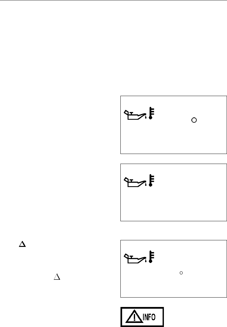
Graphic Display 153
Main Menu: Gauge
When the menu GAUGE has been se-
lected, you switch between the various
sub-menus with the up/down buttons.
•TEMPERATURE, ENGINE OIL
•TEMPERATURE, TRANSMISSION
OIL (Option)
•VOLTMETER
Temperature, engine oil
MENU: GAUGE, TEMPERATURE EN-
GINE OIL
The engine oil temperature is shown as in
the diagram.
If the sensor data for Temperature, engine
oil is not available, the symbol is shown as
well as the text NO DATA.
T3008830 185 F
T3008830 NO
DATA
Information message
Yellow INFO telltale
If the engine oil temperature becomes too
high, an information message is shown au-
tomatically with the text HIGH. At the
same time the yellow INFO telltale un-
der the display lights up. Esc acknowledges
the info message.
T3008830 HIGH
210 F
T3008860
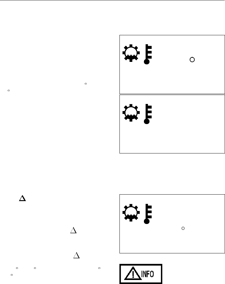
154 Graphic Display
Temperature, transmission oil (option)
MENU: GAUGE, TEMPERATURE,
TRANSMISSION OIL
The transmission oil temperature is shown
as in the diagram.
NOTE! The temperature display starts
showing only at approximately 150 F
(65 C).
If the sensor data for Transmission oil
temperature is not available, the symbol is
shown as well as the text NO DATA.
T3008831 170 F
T3008831 NO
DATA
Information message
Yellow INFO lamp
If the temperature of the transmission oil
becomes too high, an information message
is shown automatically with the text HIGH.
At the same time the yellow INFO
telltale under the display lights up. Esc ac-
knowledges the information message.
For HIGH to display with the INFO tell-
tale, the transmission oil temperature must
be 210 F (100 C) for 30 minutes, or 250 F
(120 C) for 10 minutes.
T3008831 HIGH
250 F
T3008860
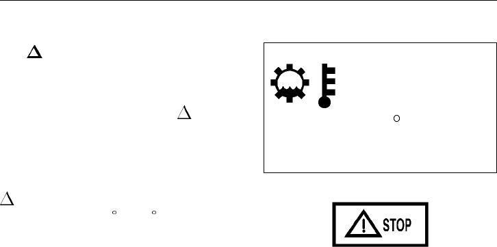
Graphic Display 155
Stop message
Red STOP telltale
If the temperature of the transmission oil
becomes too high, a flashing stop message
is shown automatically with the text TOO
HIGH. At the same time the red STOP
telltale under the display lights up and the
warning signal sounds. Esc acknowledges
the stop message.
For TOO HIGH to display with the
STOP telltale, the transmission oil tem-
perature must be 285 F (140 C) for 30
seconds.
T3008831 TOO HIGH
285 F
T3008861
156 Graphic Display
Voltmeter
MENU: GAUGE, VOLTMETER
The battery/charging voltage is shown as in
the diagram. If the battery/charging voltage
becomes too low (below 9.5 V), the instru-
ment cluster will lose power.
T3008832 13.1 V
Information message
Yellow INFO telltale
If the battery/charging voltage becomes too
high, the voltmeter’s value is shown auto-
matically as well as the text TOO HIGH.
At the same time the yellow INFO tell-
tale under the display lights up.
T3008832 TOO HIGH
17.9 V
T3008860
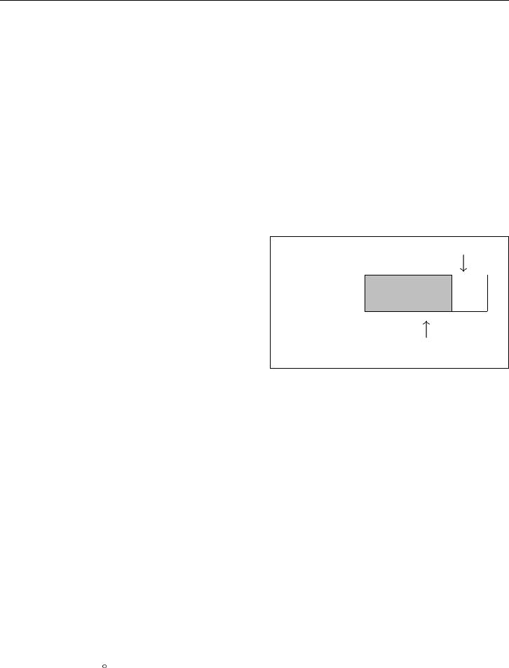
Graphic Display 157
Main Menu: Fuel Economy (option)
Menu FUEL ECONOMY has 2 sub-
menus:
•AVG/INST
•LEG FUEL
FUEL ECONOMY is chosen and then the
up/down buttons are used in order to
change between the available sub-menus.
AVG/INST Fuel Economy
MENU: FUEL ECONOMY, AVG/INST
For setting metric or English value dis-
plays, see page 126.
The following is shown on the display:
•Average trip fuel consumption (AVG):
The value is presented numerically
and as an arrow above the bar. The ar-
row’s position shows the value. For a
short time after resetting, the following
is shown “— — — “ instead of the
average fuel consumption.
•Instantaneous fuel consumption
(INST):
The value is presented numerically as
well as in the form of a bar.
•Target trip fuel consumption (TAR-
GET):
The value is presented as an arrow un-
der the bar. The arrow’s position
shows the value. This value is pass-
word protected, see page 152.
NOTE! When idling, the bar is not shown
and the fuel consumption is shown in
gal/hour.
NOTE! If km and Chave been selected
the consumption is shown in liters. In the
example above, L/100 km will then be
shown instead of mpg.
AVG
9.9
INST
8.0
mpg TARGET

158 Graphic Display
Reset fuel economy
1 Press SELECT in the menu
AVG/INST.
2 A new text message in the form of a
question is shown:
RESET FUEL DATA? Press SELECT
to reset.
When the leg’s fuel consumption is reset,
the average fuel consumption will also be
reset.
RESET
FUEL DATA?
PRESS SELECT FOR 1S
Leg Fuel
MENU: FUEL ECONOMY, LEG FUEL
Press the up/down buttons in the menu
AVG/INST to reach the menu LEG FUEL.
The following is shown in the menu LEG
FUEL on the display:
•The Leg fuel consumption (amount of
fuel used since the last resetting).
•Empty XXX mi (where XXX is the
calculated range using the present in-
stantaneous consumption).
NOTE! If km and Chave been selected,
the consumption is shown in liters. In the
example below, L will then be shown in-
stead of USgal.
NOTE! Since the ”calculated range” is
based on the instantaneous consumption,
the correct value is first shown shortly after
start.
LEG FUEL
XXX
EMPTY XXX mi

Graphic Display 159
Main Menu: Time/Distance
Menu TIME/DIST has 4 sub-menus.
•CLOCK
•ALARM CLOCK
•TRIPMETER
•AVERAGE SPEED
NOTE! Menu TIME/DIST is available
even when the ignition key is in the off po-
sition. It is activated by keeping one of the
control buttons on the wiper stalk pressed
down for at least 1 second. The menu re-
mains active for 30 seconds after the last
depressing of the button.
The alarm clock cannot be set while driv-
ing, but the buzzer which sounds for the
alarm call can be switched off, see page
162.
Clock
MENU: TIME/DIST, CLOCK
Shows the current time. To set the time for-
mat 12h or 24h, see page 128.
Setting
1 To set the clock, press SELECT when
you are in the menu
TIME/DISTANCE and the clock
function will be shown.
2 Set the hours with the up/down
buttons. Confirm the choice with SE-
LECT.
3 Set the first digit in the minutes with
the up/down buttons. Confirm the
choice with SELECT.

160 Graphic Display
4 Set the second digit in the minutes
with the up/down buttons. Confirm the
choice with SELECT.
5 Set the AM/PM (if the time format is
12h) with the up/down buttons. Con-
firm the choice with SELECT. 12:00
Cancel setting
When setting hours, Esc cancels the setting
and the time is shown according to the pre-
vious setting.
Pressing Esc after setting the minutes or af-
ter setting the AM/PM, moves the cursor
back to the previous selection.
Ignition key in the off position
When the ignition key is in the OFF posi-
tion, if setting the clock takes more than 30
seconds between pushing the buttons, the
time which has been entered then applies.

Graphic Display 161
Alarm clock
MENU: TIME/DIST, ALARM CLOCK
Setting the alarm clock:
1 To set the alarm clock, press SELECT
when the menu ALARM CLOCK is
shown in the menu TIME/DIST.
2 Move the cursor to SET using the
up/down buttons. Press SELECT.
If the speed during the setting exceeds
5 mph (8km/h), the function is can-
celled and the graphic display returns
to the last active display in the ON po-
sition.
3 Set the hours with the up/down
buttons. Confirm the choice with SE-
LECT.
4 Set the first digit in the minutes with
the up/down buttons. Confirm the
choice with SELECT.
5 Set the second digit in the minutes
with the up/down buttons. Confirm the
choice with SELECT.
6 Set the AM/PM (if the format is 12h)
with the up/down buttons. Confirm the
choice with SELECT.
7 Move the cursor to ON using the
up/down buttons. Press SELECT. A
symbol is shown on the right in the
graphic display window’s status bar in
order to highlight that the alarm clock
is activated.
8 Esc moves the highlight to the previ-
ous number or selection, if there are
any, otherwise the setting is cancelled.
ALARM 08:30 AM
CLOCK 08:00 AM
ON OFF SET
T3008833
162 Graphic Display
Ignition key in the off position
When the ignition key is in the OFF posi-
tion, if setting the alarm clock takes more
than 30 seconds, the time which has been
entered then applies.
Switch off the alarm clock
When the alarm clock goes off, the word
ALARM flashes, the current time is shown
and a warning signal sounds. The alarm is
switched off after 60 seconds or when the
up, down, Esc or SELECT control button is
pressed.
Activate alarm clock (without changing the time of the alarm call)
1 The cursor is moved with the up/down
buttons to ON.
2 SELECT activates the alarm clock and
the symbol is shown on the graphic
display.
Cancel setting
Press Esc in order to cancel the setting.
ALARM 08:30 AM T3008833
CLOCK 08:00 AM
ON OFF SET
De-activate the alarm clock
1 The cursor is moved with the up/down
buttons to OFF.
2 SELECT switches off the alarm clock
and the symbol disappears from the
graphic display.
Cancel setting
Press Esc in order to cancel the setting.
ALARM 08:30 AM
CLOCK 08:00 AM
ON OFF SET

Graphic Display 163
Tripmeter
MENU: TIME/DIST, TRIPMETER
On the display in the menu TRIPMETER
the distance driven for Leg 1 and Leg 2 are
shown.
TRIP
#1 43.6 mi
#2 507.3 mi
Reset tripmeter
1 Press SELECT in the menu TRIPME-
TER.
2 A new text message with a question
about the resetting of the tripmeter is
shown. The up/down buttons move the
cursor between Leg 1 and Leg 2. Con-
firm the choice with SELECT or press
Esc in order to cancel the resetting.
RESET?
#1: #2:
PRESS SELECT FOR 1S
Average speed
MENU: TIME/DIST, AVERAGE SPEED
The average speed is calculated using the
distance driven divided by the time the en-
gine has been running (since the last
resetting).
AVERAGE
SPEED
55.4 mph
Reset average speed
1 Press SELECT when the menu AV -
ERAGE SPEED is shown.
2 A new text message with a question
about the resetting of the average
speed is shown. Confirm the choice
with SELECT or press Esc in order to
cancel the resetting.
RESET?
PRESS SELECT FOR 1S

164 Graphic Display
Main Menu: FAULTS?
General
When a fault occurs a fault message is
shown on the graphic display. There are
two types of fault messages:
1 Information messages
2 Stop messages
The stop message is always more urgent
than information messages.
Any information and stop messages as well
as the associated symbols are shown auto-
matically on the graphic display when
driving. A summary of these symbols is
shown in the illustration under page 166.
Under the display there are two lamps (a
yellow INFO telltale and a red STOP
telltale) that attract the driver’s attention
when necessary. When the red (stop) tell-
tale lights up and the engine is running, a
warning signal is also activated.
Several messages may be active at the same
time. When a new message is activated the
new one is shown instead of the old one.
A down arrow in the graphic display’s
right-hand corner means that more mes-
sages are active.
Graphic Display 165
Information message
The yellow INFO telltale lights up when
an abnormal state or a risk situation is indi-
cated. In addition to the telltale, a symbol
or text is shown on the graphic display at
the same time. For certain symbols, a mea-
surement value is also shown.
NOTE! In the event of a warning for low
air pressure no message is shown on the
graphic display, the LED in the gauge
lights up instead (together with the master
warning telltale [see page 78]).
Important! When the INFO telltale
lights up, the specified fault must be
checked at the next stop.
T3008860
Stop message
In the event of serious faults, the red
STOP telltale lights up and a warning
buzzer sounds (if the engine is running). In
addition to the telltale, a symbol or text is
shown on the graphic display at the same
time. For certain symbols, a measurement
value is also shown.
NOTE! In the event of a warning for low
oil pressure or coolant temperature in the
engine no text is shown on the display —
the LED in the respective gauge lights up
instead.
WARNING
When the STOP telltale lights up the
vehicle must be stopped immediately.
T3008861
166 Graphic Display
Information symbols
The yellow INFO telltale lights up and a
symbol is shown on the graphic display:
Airbag
For airbag (SRS sys-
tem) information, see
page 57. T3008842
Overheating, in-
struments
The symbol will be
shown when the tem-
perature in the
instrument cluster ex-
ceeds 92 C (198 F).
The instrument lighting
becomes weaker and
the gauges show the
minimum reading.
When the cab tempera-
ture cools the
instrument cluster func-
tions will gradually be
restored.
T3008840
Level, washer
fluid
The symbol is shown
when there are approx.
1.4 gallons (5.3 liters)
of fluid remaining in
the reservoir.
T3008838
Warning, trans-
mission oil
temperature
If the temperature of
the transmission oil be-
comes too high, an
information message is
shown automatically
with the text HIGH. It
comes on when the
transmission oil is
250 F (120 C) or over
for more than 10 min-
utes, or 210 F (100 C)
or over for more than
30 minutes. The tem-
perature is displayed
along with the symbol.
T3008831
Warning, volt-
meter
If the battery voltage
becomes too high the
voltmeter’s value is
shown automatically as
well as the text TOO
HIGH. This warning is
triggered at 17 V. The
voltage is displayed
along with the symbol.
T3008832
Graphic Display 167
Warning, tem-
perature engine
oil
If the engine oil tem-
perature becomes too
high, a stop message is
shown automatically
with the text TOO
HIGH. The engine out-
put is reduced. The
temperature limit which
activates this warning
varies for different en-
gines. This limit is set
in the engine ECU.
T3008830
Air filter,
clogged
The symbol is shown
when the air filter sen-
sor is restricted. T3008843
Too cold for en-
gine brake
(VEB) (Volvo
engine only)
Position 2 on the
switch must not be en-
gaged before the engine
has reached operational
temperature. If position
2 is engaged and the
engine is too cold, this
symbol is shown and a
signal sounds when en-
gine braking is carried
out (However, VEB is
not engaged).
T3009913
Fault in the pre-
heating
T3008841
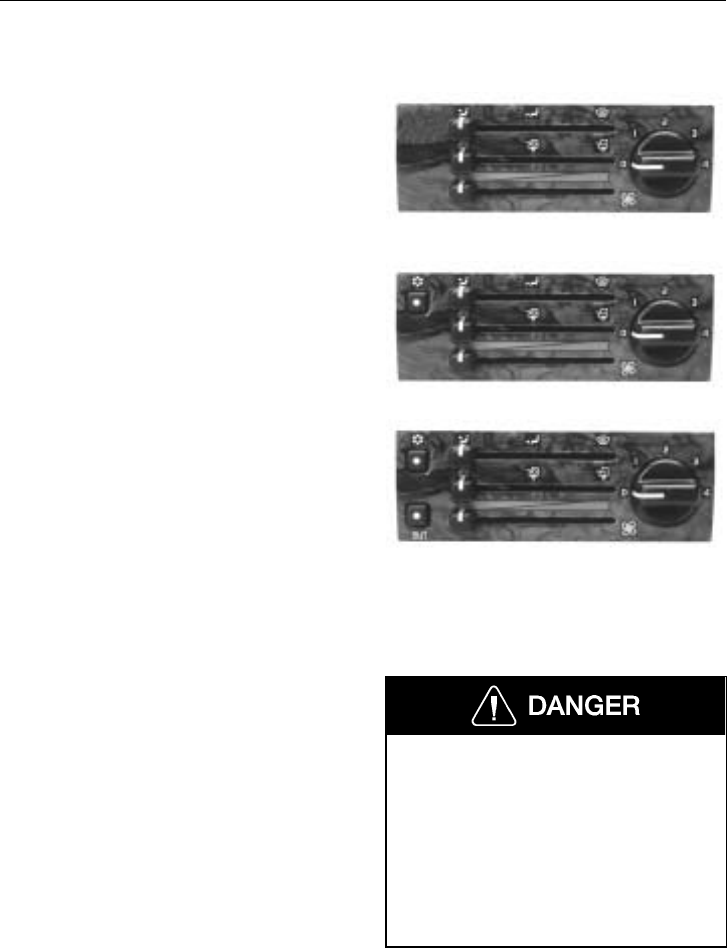
168 Heating and Air Conditioning
General
Three levels of the cab climate systems are
available. They can be identified by the ap-
pearance of the control panel.
The basic system is a heater and defroster
unit only. The heater unit has a rating of at
least 40 000 Btu. W8001116
The manually operated heating and air con-
ditioning unit is controlled from the same
panel as the heater system, with the
addition of a switch for turning the air con-
ditioning system on (button with the
snowflake symbol).
W8001003
A variant of the air conditioning system
can be added as an option. This is called
the Automatic Temperature Control (ATC)
variant. It is identified with the switch
marked aut. It allows all functions of the
previous systems, plus the ability to main-
tain the temperature in the cab as set by the
driver. The desired temperature is selected
by the combination of the temperature con-
trol setting and the fan speed.
W8001004
The air conditioning only operates when
the engine is running. Best performance
from the air conditioning is achieved when
all windows and vents are closed. At all
times, make sure the cowl fresh air intake
is free from snow, ice, leaves, etc.
NOTE! The air conditioning system is con-
tinuously monitored for correct function.
The monitor module has a read-out for fault
codes. See page 179 for more information.
Do not attempt to drive with the wind-
shield covered by mist, fog or frost. The
visibility is reduced which could lead to
an accident causing severe personal in-
jury or death. Read these instructions to
be able to hold the windshield clear at
all times. Maximum heat output for fast
defrosting can only happen after the en-
gine has reached operating temperature.

Heating and Air Conditioning 169
Climate Unit Main Control Panel
Fan Speed Control
The fan has four speeds and can also be
shut off. With the fan control in the 0 posi-
tion, air still flows out of the dash vents if
the vehicle is moving at highway speeds
and if the Fresh Air Control is set for out-
side air intake. If the Fresh Air Control is
set for full recirculation, the fan has to be
on for air to flow out the dash vents.
If equipped with air conditioning, the fan is
not controlled by the system to change fan
speed with changing temperatures. Adjust
the fan speed to the desired air flow.
Fan speed must be selected to meet either
heating or cooling needs. For the heater
only and manual air conditioning variants
of the climate system, settings of tempera-
ture and air flow must be adjusted as often
as necessary to accommodate changing
temperatures outside and inside the cab.
The ATC system is designed to maintain a
constant temperature in the cab, which is
set by the temperature control. As the sys-
tem does not make automatic changes of
fan speed, a selection of higher or lower
fan speed to allow for more or less air flow
may have to be made to achieve the correct
temperature.
W8001466
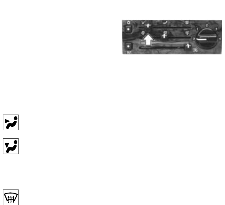
170 Heating and Air Conditioning
Air Distribution Control
The air distribution control is used to direct
the air flow to either the dash vents, floor
vents or defroster vents. The lever has de-
tentes in the outer and middle positions so
that it can be set without looking at the
panel.
The air flow for the three major settings are
described below. Any setting outside of the
detented positions will be a mix of the air
flows that depends on how far from the de-
tented position the lever is.
W8001467
With the control in the leftmost
position, all air is directed out
through the vents in the dash.
With the control in the middle
position, most air is directed out
through the floor vents and the
cab door window vents. A small
flow is directed out through the
vents in the dash. This mix is
approximately 80/20.
With the control in the right-
most position, most air is
directed out through the front
dash vents to the windshield and
cab door windows. A small flow
is directed out through the vents
in the dash. This mix is approx-
imately 70/30.
NOTE! When the air vents on the dash are
open, some air always flow through them.
To have maximum air flow to the floor or
to the windshield and cab door windows,
close the dash vents.
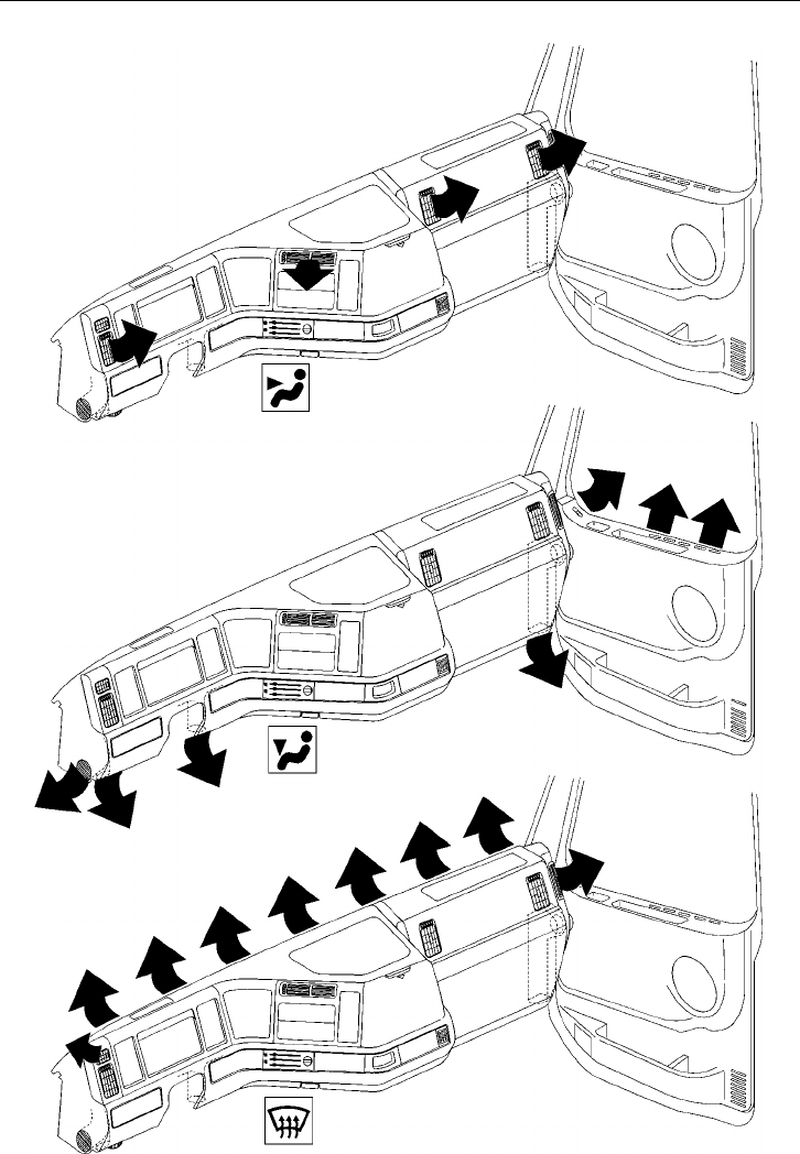
Heating and Air Conditioning 171
W8001078
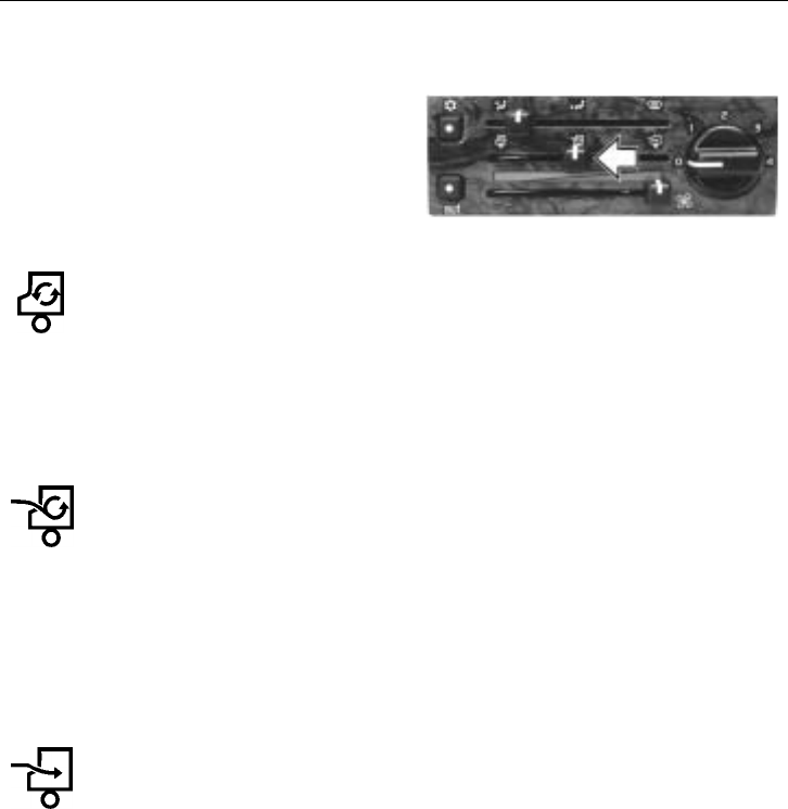
172 Heating and Air Conditioning
Fresh Air Control
The top slide lever is the Fresh
Air/Recirculation Control. The settings can
be anywhere from full fresh air intake to
only recirculated air. Settings can be chosen
anywhere in between to give the desired
flow of air. W8001468
In the leftmost position, the
fresh air inlet is closed. All air
is recirculated within the cab. It
can be used to heat up or cool
down cab temperature quickly
or to close intake from letting in
odors, etc. with the intake air.
In the middle position, there will
be a 20% addition of fresh air
to the 80% of recirculated air.
This position is well suited for
use when the air conditioning is
engaged so a minimum of warm
or cooled air is lost through the
evacuation vents, while fresh air
is still added to the cab.
In the rightmost position, the
fresh air inlet is completely
open. This is best used when
heat is required (wintertime)
and when defrosting or de-icing.

Heating and Air Conditioning 173
Temperature Control
The bottom slide lever is the Temperature
Control which operates the coolant control
valve. In the leftmost position the flow of
coolant is shut off by the control valve,
which means no heat from the climate unit.
The heat will increase the further to the
right the control is moved.
The temperature control should be used as
a thermostat, together with the fan speed, to
“dial” in the desired temperature when
using the air conditioning. The desired tem-
perature is selected by the combination of
the temperature control setting and the fan
speed. For the ATC version, the tempera-
ture is automatically maintained to where
the control was set. If needed, the control
can be moved to a new setting without
turning the ATC off.
Using the heater on days when the outside
temperature is low but there is direct sun-
light heating through the windows, the air
distribution control should be set in the
center position (air directed to the floor)
and the air vents open, and at the same
time, the temperature control should be set
around the middle position. Warm air is
then distributed so that it is warmest at the
floor and cooler air is distributed via the air
vents on the dash.
When the temperature control is set in one
of the end positions, the temperature at the
floor vents and the air vents is the same.
W8001469

174 Heating and Air Conditioning
A/C Control
When the vehicle is equipped with air con-
ditioning, the control panel has a button for
engaging the air conditioning compressor.
This button is marked with a snowflake
symbol. When the A/C is engaged, the
green LED light in the button is on.
When the air conditioning button is
pressed, the fan speed control must be set
on 1 through 4 for the air conditioning to
start. If the air conditioning button is
pressed when the fan speed control is set
on 0, the air conditioning will not start.
To set the air conditioning temperature, ad-
just the temperature control and fan speed
until the desired temperature/air flow has
been reached. If the cab temperature needs
adjusting, the temperature or fan speed has
to be adjusted again until the new desired
temperature has been reached.
W8001470

Heating and Air Conditioning 175
A/C Automatic Control
When the vehicle is equipped with Auto-
matic Temperature Control (ATC), the
control panel has a button, marked with
aut, for engaging the electronic control
unit. When ATC is engaged, the green LED
light in the button is on.
The ATC air conditioning works with the
coolant control valve as a “thermostat,”
making automatic adjustments with input
from sensors for air output and for air in-
side of the cab. However, the fan speed
may also have to be adjusted, increasing or
decreasing air flow, to achieve correct cab
temperature.
To use the ATC, let the system run in the
manual mode until the cab temperature has
stabilized at a desirable temperature. Then
press the aut button to engage the auto-
matic control unit. To set a new desired
temperature, simply slide the temperature
control to a higher or lower setting and the
system will maintain this new temperature
within the ability of the temperature control.
NOTE! Changing from manual to ATC
control or the other way, makes the air out-
put temperature change 5 to 10 degrees. A
small correction to the temperature control
is needed after the change has been made.
W8001471
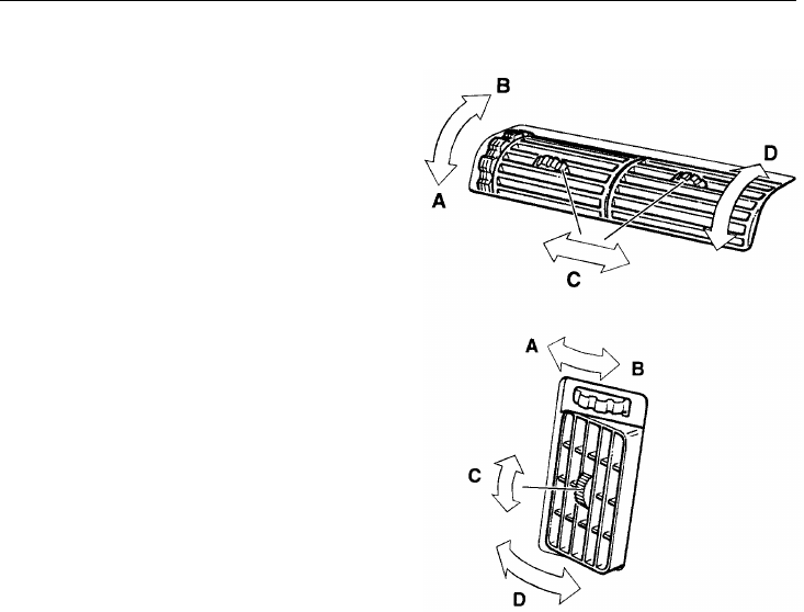
176 Heating and Air Conditioning
Air Vents
AClosed
BOpen
CLateral Air Flow
DVertical Air Flow
When heating the cab, all vents should be
closed. However, the vents on the outer
parts of the dash can be used for defrosting
the cab door windows. When operating the
air conditioning, all air vents should be
completely open and the air flow directed
upward.
W8001150
Heating and Air Conditioning 177
Cab Ventilation
Ventilation Guidelines
If at any time there is any doubt that ex-
haust fumes are entering the cab, have the
cause of the fumes determined and cor-
rected as soon as possible. If the vehicle
must be driven under these conditions,
drive only with all windows open.
Protect against carbon monoxide entry into
the cab. Keep the engine exhaust system,
cab and cab ventilation system properly
maintained. It is recommended that the ex-
haust system and cab are inspected by a
competent technician:
•At every engine oil change.
•Whenever a change is noticed in the
sound of the exhaust system.
•Whenever the exhaust system, under-
body or cab is damaged.
Do not breathe the engine exhaust gas. It
contains carbon monoxide, which has no
color or odor. Carbon monoxide is a
dangerous gas which can cause uncon-
sciousness or death.
Diesel engine exhaust and some of its
constituents are known to the state of
California to cause cancer, birth defects
or other reproductive harm.
To allow for proper operation of the vehicle
ventilation system, keep the inlet grille at
the base of the windshield clear of snow,
ice, leaves and other obstructions at all
times.
Do not park the vehicle and let the engine
run or idle for more than 10 minutes with
the ventilation system control switch in the
off position. Even with the ventilation sys-
tem on, running the engine while parked or
stopped for long periods of time is not rec-
ommended. Entry of carbon monoxide into
the cab is possible with a poorly repaired,
damaged or corroded exhaust system or cab.
Do not run the engine in confined areas,
such as garages or next to a building, any
more than necessary. The area must be
properly ventilated. When the vehicle must
be stopped with the engine running for
more than a few minutes:
•Adjust the heating or cooling system
to force outside air into the cab. Do
this by setting the fan to medium or
high speed and with the controls set in
any position except for recirculation of
air inside of the cab.
•Keep the exhaust pipe area clear to
help reduce the buildup of exhaust gas
under the vehicle.
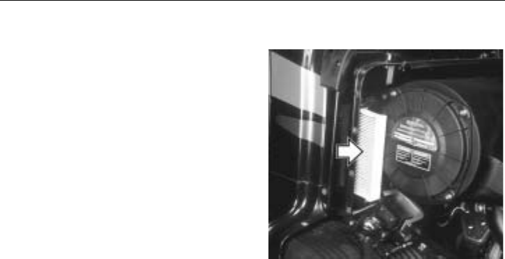
178 Heating and Air Conditioning
Cab Air Filter
Air going into the cab passes a filter lo-
cated on the right, front side of the cab.
Remove the filter and clean with an air gun
(no more than 20 psi pressure) after 40 000
miles (64 000 km), (in dusty conditions as
often as every 10 000 miles [16 000 km]).
Make sure the air stream is directed from
the inside out.
The filter should not be cleaned and reused
more than once. Replace with a new filter
after maximum 70 000 miles (110 000 km),
or earlier if driving in dusty conditions. A
clogged filter decreases the efficiency of the
air conditioning system. W8002474
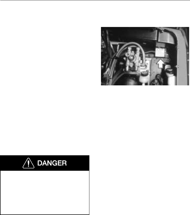
Heating and Air Conditioning 179
A/C Diagnostic Module
Problem Codes
The diagnostic module has two LED lights
(one green and one red) which indicate if a
system problem has been detected. If a
problem is detected, a fault code or “blink”
code is activated to identify the condition.
The blink codes listed on the label are:
Slow Green Normal
Fast Green Low system voltage
1 Red Blink Loss of refrigerant
2 Red Blinks Overcharge, blockage or
fan failure
3 Red Blinks Open or shorted clutch
or circuit
4 Red Blinks Open pressure switch or
circuit
The air conditioning system is under
pressure. The possibility of an explosion
is possible if serviced incorrectly. A
qualified technician should perform any
service needed. Failure to follow this
may lead to an explosion causing severe
injury or death.
W3002004
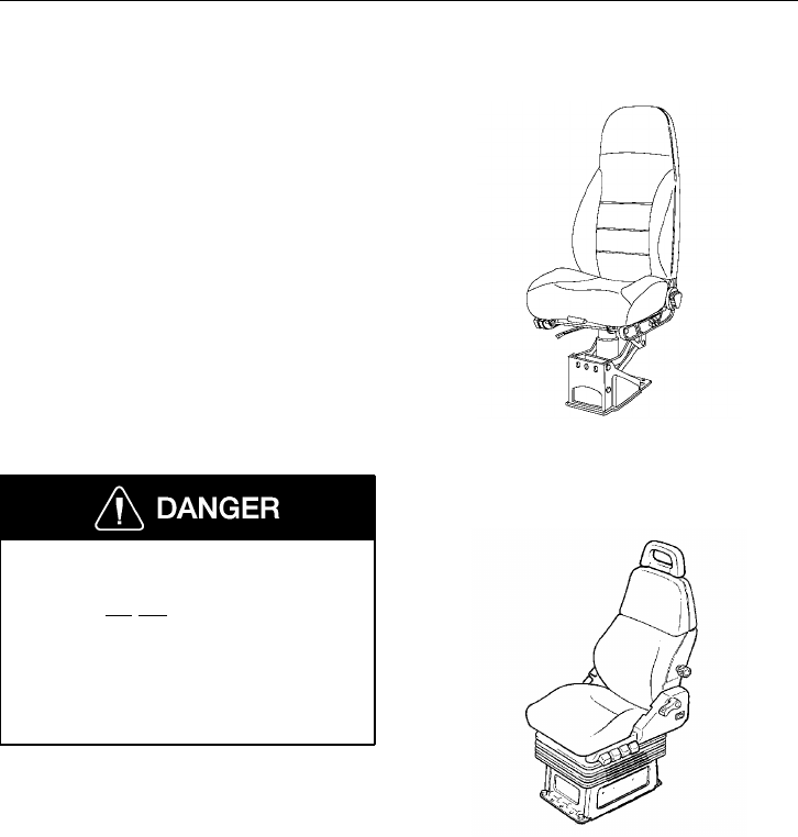
180 Seats
General
Several different seats can be used in the
vehicles. If the seat installed in the vehicle
is not explained in this section, look for the
seat manufacturer’s manual in the Owner’s
Package.
On the driver’s side there is a standard seat
and an upgrade that includes adjustable air
cushions for lumbar and thigh-back sup-
port, arm rests and a frame cover.
The passenger side can have the same type
of seat as on the driver’s side and also a
fixed seat. Each of the seats are described
on the pages that follow.
All adjustments are to be made while
the operator is seated and the vehicle is
stationary. Do not adjust the seat posi-
tion while driving the vehicle. Failure to
follow this warning can result in loss of
vehicle control, which can result in seri-
ous personal injury or death in the event
of a crash.
Before adjusting or fastening the seat belt,
move the seat forward or rearward and ad-
just the seat height as necessary. Sit erect
and adjust the seat cushion and seat back to
obtain a comfortable driving position.
W8002743
National Standard Seat
W8002809
Volvo Standard Seat
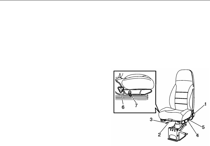
Seats 181
National Standard Seat Adjustments
1 Backrest tilt: By rotating the round
handle, the backrest recline angle can
be adjusted within 12 degrees.
2 Cushion front tilt and length: Pulling
the handle up and out adjusts the tilt
and length of the seat cushion.
NOTE! Support body weight with
your feet while adjusting.
3 Fore and aft movement: Press the lever
sideways to unlock the seat. Move seat
fore or aft to a new position.
4 Ride height adjustment: Push the up-
per part of the switch up to increase
ride height. Push the lower part of the
switch to deflate the airbag and lower
the ride height.
5 Lumbar support adjustment: Push the
upper part of the switch to inflate the
support for a firmer support. Push the
lower part of the switch to deflate the
support.
6 Cushion rear tilt: Rotate the lever to
get different height positions.
NOTE! Support body weight with
your feet while adjusting.
7 Chugger snubber: Moving the handle
down isolates the seat from the fore
and aft movement of the cab.
W8002745
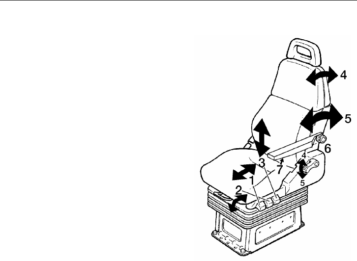
182 Seats
Volvo Standard Seat Adjustments
1 Fore and aft movement: Press the con-
trol down to unlock the seat cushion.
Move seat cushion fore or aft to a new
position.
2 Cushion front tilt: Push the control
down and adjust the tilt of the seat
cushion.
3 Ride height adjustment: Push or pull
the control to change ride height.
4 Lift the lever up to adjust the top part
of the seat back.
5 Push the lever down to adjust the
whole backrest.
6 The lumbar support is adjusted by
turning the knob clockwise for firming
and counterclockwise for slackening
the support.
7 The angle of the armrest is adjusted
with the dial control on the underside
of the armrest.
W8002387
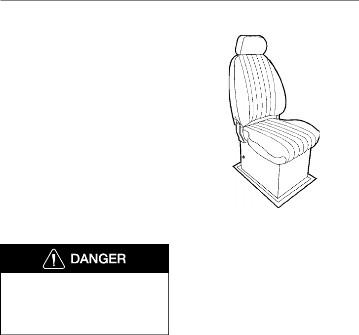
Seats 183
National Stationary Seat
For the passenger side, there is the option
of a stationary seat. The base of the seat is
a storage box that is accessed by lifting the
seat cushion up. A bench seat for two pas-
sengers is also available.
W8001386
No Passenger Seat (option)
Using a temporary passenger seating
without the benefit of proper seat
mounting and safety belt can, in the
event of a loss of control of the vehicle,
cause serious personal injury or death.
In vehicles with no passenger seat installed.
Do not let a passenger ride on temporary
seating. This is against the law and can be
very dangerous.
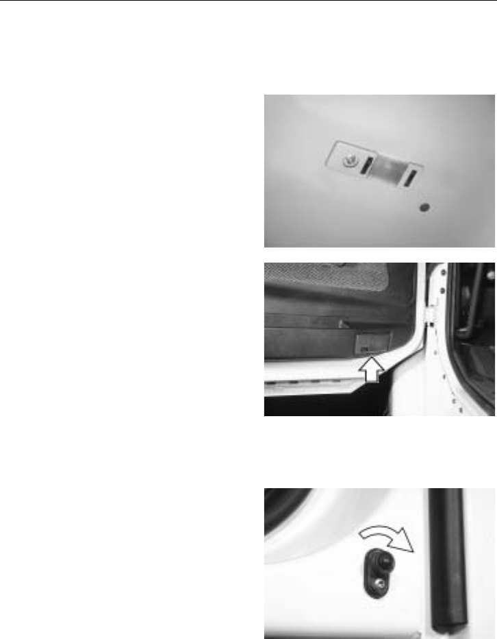
184 Cab Interior
Interior/Reading Lights
Front Of Cab
The cab is equipped with separate and com-
bined interior and reading lights in various
locations in the cab. The front seat overhead
lights can be turned on at any time using
the switch in the fixture. By turning the
switch the other way, the light will be acti-
vated by the cab door switches. Any time
the door is opened, the light will come on.
W3004387
There is also a light on the inner front face
of the door that can be activated by the
switch or be set to come on when the door
opens. The lens is red so the light is used to
alert oncoming traffic from the rear that the
door is open. It is also used during night
driving to light up the floor area without
distracting the operator with a glaring light.
W3000974
The door switch operates all door-activated
lights. The switch is located in the rear part
of the door frame.
The switch has a shut off function that can
be used if the door needs to be open and
the lights should not be on. To deactivate
the lights, grasp the stem of the switch with
two fingers, push it in and twist clockwise.
The stem stays in and the light is off.
When the switch stem is pushed in and re-
leased, either by hand or by the door, it
will return to the normal working position.
W3000970
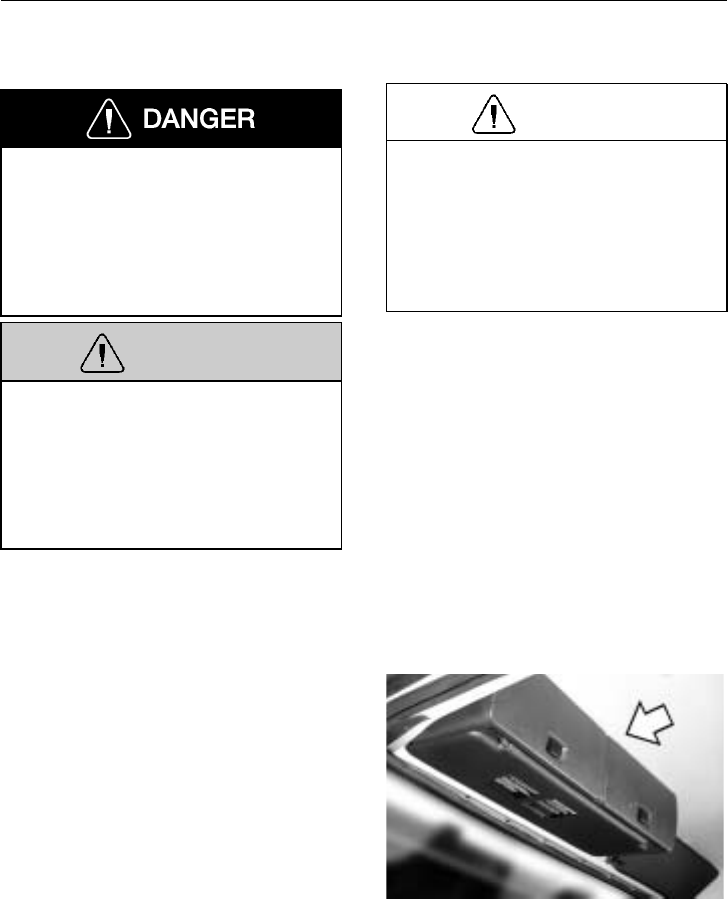
Cab Interior 185
Storage Compartment
Heavy objects must be stored secured to
the floor. Storage compartments are de-
signed for lighter personal effects only.
In the event of a collision, heavy, unse-
cured objects in overhead storage can
come loose and cause severe personal in-
jury or death to the driver or passengers.
WARNING
All items within the cab must be secured
before the vehicle is set in motion. This
includes, but is not limited to, drinks,
clothes, books, tools, etc. In the event of
a collision, loose items could fly around
inside the cab. This could cause personal
injury.
CAUTION
Do not overload the cab suspension.
Make sure the weight distribution is
equal in the cab. Total load for the cab
suspension is 800 lb (360 kg), with
driver and passenger included. Overload-
ing the suspension leads to poor ride and
a lowered driving comfort.
Front Overhead Storage
There are several combinations of the over-
head storage compartments mounted over
the windshield. The compartments are split
in the middle and they can be combined to
cover the whole width of the cab or just
over the driver.
The storage compartments have a maxi-
mum storage weight limit of approximately
18 lb (8 kg) per section. That is, the limit
covers each compartment section, either left
or right side. W8001098
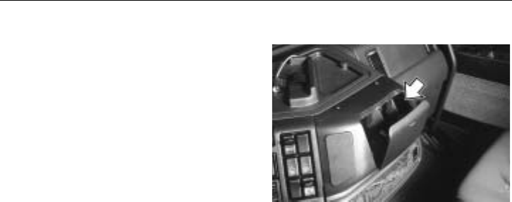
186 Cab Interior
Cup Holders
There is also a cup holder in the middle of
the dash. To open, press the top part of the
lid in and the lid will fold out. To close,
press the lid in until the latch closes.
There are also two cupholders molded into
the engine cover.
W8001875
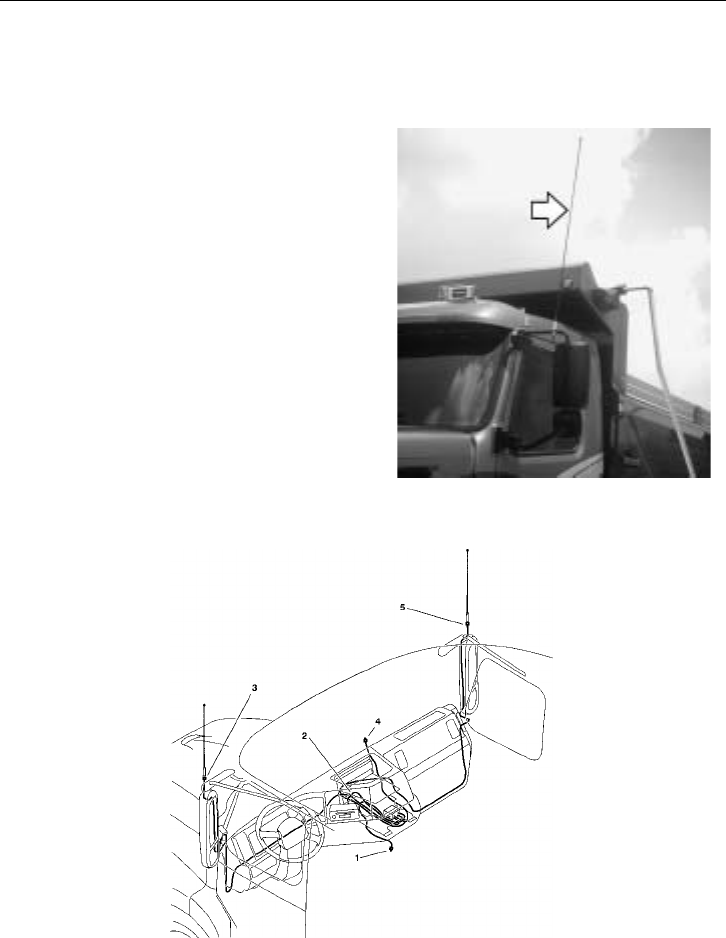
Communication and Entertainment 187
Antennas
Multiband Antenna
There are antennas mounted on the top of
the mirror brackets for wideband reception.
They receive or send signals for radio, CB
and telephone. Each antenna carries multi-
ple wire windings that work together with
mirror bracket devices to cover the needs of
many uses.
If the antenna is damaged, replace it only
with a multiband type antenna. A regular
antenna does not have the wiring necessary
to give good reception for all uses.
W3004388
Antenna Multiplexer
W3004430
1 Cellular Phone Antenna Cable
2 Radio Antenna Cable
3 Left Side Antenna
4 CB Radio Antenna Cable
5 Right Side Antenna
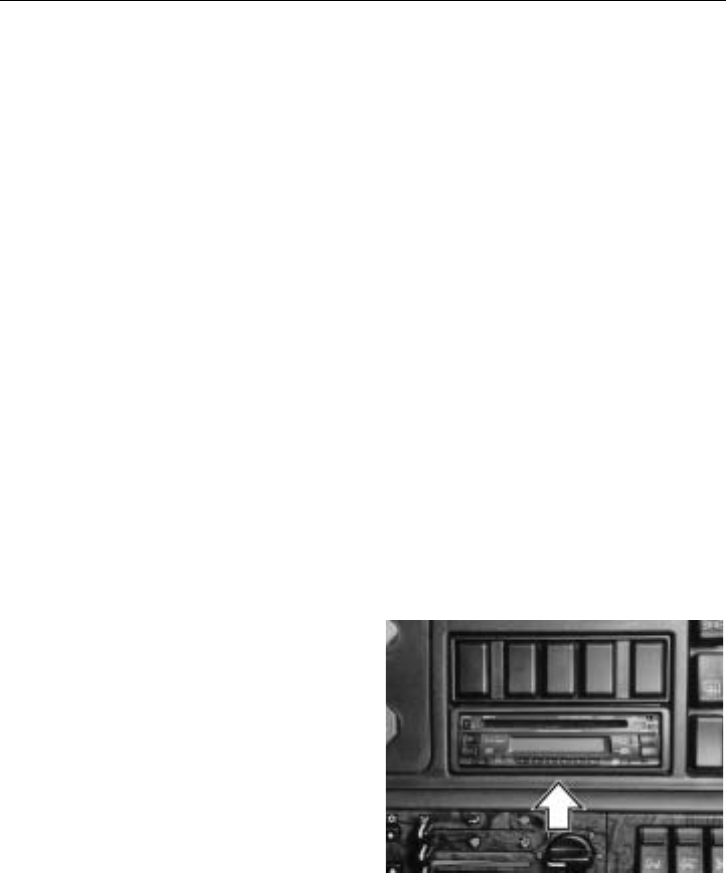
188 Communication and Entertainment
Communications signals that travel to and
from the antennas go through the antenna
multiplexer. Coaxial cables for the cellular
phone, CB radio and radio are included in
the multiplexer system – all using the same
set of antennas.
The multiplexer is accessed through the
lower dash panels. Cable routing is as
shown in the illustration above. Use only
genuine Volvo replacement parts for this
multiplexer system; standard antennas will
give unsatisfactory performance. The wind-
ings in the antennas are specific to this
system: different sections of the antenna are
used for the cellular phone, radio and CB.
Stereo/Radio
Stereo
The radio is mounted in the right hand side
of the dash. Several models are available,
from a basic unit to top of the line.
Depending on the model, there are some
important features built into the unit. Take
the time to read the manufacturer’s manual
to be able to operate the various functions,
such as theft-deterrent coding.
W3002006
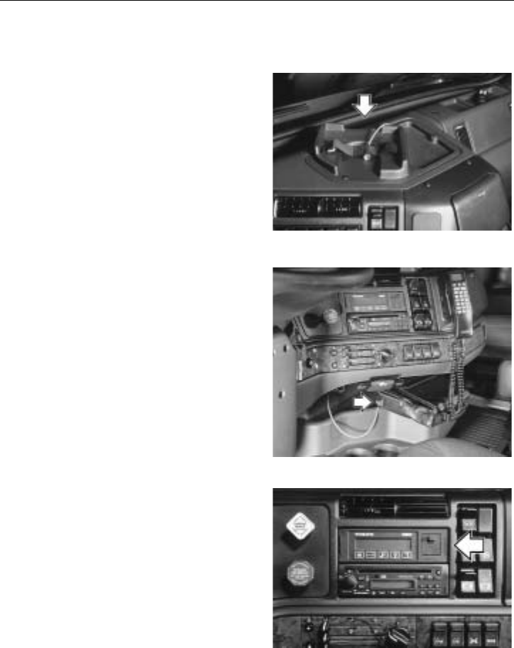
Communication and Entertainment 189
Communication Equipment
CB Radio
There is an optional platform provided for
a CB radio on top of the dash. The unit is
held in place with a strap which can ac-
commodate a variety of sizes. For electrical
hook-up, see page 255.
The CB Radio can also be permanently
mounted directly above the radio. When the
optional switch panel is removed, a DIN
standard radio mount is available.
W8001876
Telephone
There is room on the dash for a mobile
telephone. This can be hooked up to the
multiplex box.
If the vehicle is delivered with a multiplex
box, the connecting end of the telephone
coaxial cable should be located at the lower
dash cover.
W3002427
Road Relay
The Road Relay is an engine communica-
tion tool that allows the driver to have fuel
consumption, time and mileage readouts
and also programmed reminders for service
intervals. The Road Relay should be per-
manently mounted directly above the radio.
Collected data can be downloaded for use
in a stationary computer where the data can
be collected and compared over time.
W3002420

190 Fuel Economy Driving
Fuel Economy
General
The absolute fuel consumption (counted in
miles per US gallon or liters per 100 kilo-
meters) is determined by a large number of
circumstances which can be related to one
of the following main areas:
1 Build specification and equipment
2 Service and maintenance
3 External environment
4 Driving habits
Due to these factors, fuel consumption can
vary considerably within what is called
“normal fuel consumption.” Fuel consump-
tion can vary from over 10 mpg (20 L/100
km) when driving empty on a nice and dry
summer road to 3.5 mpg (70 L/100 km)
while driving with maximum permitted
GVW, with vehicle and trailer, on a hilly
and slushy winter road.
Build Specification and Equipment
Whenever a vehicle is used for transporta-
tion, its build specification, equipment and
gross vehicle weight have a decisive effect
on both fuel consumption and performance.
The factors which have the greatest influ-
ence on fuel consumption are primarily:
driveline combination, height of trailer or
superstructure, use of air fairings, tire type,
number of wheels, gross vehicle weight,
and accessories.

Fuel Economy Driving 191
Driveline Combination
Engine, transmission and final drive must
be selected in such a way that the engine
can operate within the economic speed
range at normal driving speed. This range is
defined as where the engine makes the best
use of the energy content of the diesel fuel.
A poorly selected rear axle ratio, which re-
sults in the engine speed being constantly
above the optimum speed, will increase
fuel consumption.
Superstructure and Air Fairings
The frontal area of the vehicle and
trailer/superstructure is what pushes the air
aside. The smoother the transition between
the aerodynamic front and cab to the
trailer/superstructure, the better the airflow.
With better airflow, the engine has to pro-
duce less power to push the air to the side,
especially at higher speeds.
There are partial and full air fairing pack-
ages available that should cover most
vehicle specifications and applications.
With flatbed trailers using tarpaulins to
cover the load, make sure the cover is tied
down well and presents a smooth surface.
Tires
Heavy duty treaded tires increase rolling
resistance considerably. For long haul,
choose a smoother, ribbed type tire. Choose
a lugged type tire only when the added
traction in mud and snow is needed.
The number of wheels (axles) has a direct
effect on the rolling resistance and, thereby,
the fuel consumption. For volume and/or
low weight transports, the use of a 4X2 in-
stead of a 6X4 should be considered.

192 Fuel Economy Driving
Gross Vehicle Weight
The gross vehicle weight of a vehicle com-
bination has a large impact on the rolling
resistance.
Accessories
As a rule, accessories such as roof rack, ad-
vertising signs, bug screens, exposed air
horns, etc., have a negative effect on fuel
consumption.
Service and Maintenance
A modern heavy-duty vehicle requires reg-
ular and preventive maintenance to ensure
that all its components function as they
should. Use the recommended preventive
maintenance (PM) program that Volvo
Trucks North America, Inc. has developed
for the vehicles. This ensures optimal en-
ergy efficiency from all components that
are important to fuel consumption.
Tires
If the tire pressure is too low, the rolling
resistance increases and, thereby, increases
the fuel consumption. The overall economy
is also affected as tire wear increases
considerably.
Brakes
Dragging brakes increase fuel consumption.
They should be checked regularly. It is im-
portant that the release action of the air
valves is fast and that the moving parts of
the wheel brakes are checked for good ad-
justment and operation.

Fuel Economy Driving 193
Axles
An axle out of alignment will increase
rolling resistance. Regularly check the front
wheel alignment and axles on both the trac-
tor and trailer/semi-trailer. If they are
correct, there will be less rolling resistance
and, therefore, lower fuel consumption.
A good sign of an axle or wheel out of
alignment is uneven tire wear. Check the
tires often.
Engine
Faulty or incorrectly adjusted engine com-
ponents increase fuel consumption. The list
below gives some typical components that
can influence fuel consumption:
•Blocked (on the outside) charge air
cooler/radiator package
•Faulty thermostats
•Blocked fuel filter
•Blocked air intake filter
•Faulty injectors
•Dirty turbo charger
•Air in fuel system
•Faulty fuel supply pump
•Faulty fuel relief valve
•Faulty fan thermostat/clutch

194 Fuel Economy Driving
External Environment
Under unfavorable conditions, the external
environment can have a negative effect on
fuel consumption. This can be broken down
into two main groups: weather and wind;
and the nature of the roads. Rain, snow, icy
conditions and headwinds have a large neg-
ative impact on fuel economy, as do hilly
roads and uneven road surfaces.
Headwinds
Headwinds have a large negative impact on
fuel consumption. With tailwinds, fuel sav-
ing is only marginal.
Air Temperature
Low ambient temperature contributes to in-
creased fuel consumption.
Rain, Snow and Road Surface
A wet road surface increases rolling resis-
tance and, thereby, fuel consumption. Slush
will increase consumption even more. In
certain cases, the surface structure of the
road can also have a negative effect on fuel
consumption.
Gradients
A hilly road with many bends demands a
higher output from the engine. The differ-
ence between flat, straight roads and hilly,
winding roads can amount to as much as a
50 percent increase in fuel consumption.
When choosing your route, avoid hills,
rough roads and frequent stops. Every stop
from 45 mph (70 km/h) can cost up to an
extra one quart (one liter) of fuel.

Fuel Economy Driving 195
Driving Habits
The way in which a vehicle is being driven
is the one factor which has the greatest in-
fluence on fuel consumption. Correct
driving saves fuel and reduces vehicle wear.
To achieve optimal running economy, the
driver should always remember to:
•Start the engine correctly (especially
important in winter season)
•Maintain an even and correct speed
•Keep the engine at its optimum speed
range
•Use the correct uphill and downhill
driving technique.
Starting the Engine
Start the engine according to the instruc-
tions in the Operator’s Manual of the
engine manufacturer (for a Volvo engine,
see page 198). A proper start, especially
during the cold season, saves fuel and re-
duces engine wear.
Sluggish lube oil in the engine makes cold
starting more difficult. Therefore, it is im-
portant to always use engine oil with the
correct viscosity. (For the sake of the over-
all fuel economy, it is also important to
have the right viscosity of transmission and
rear axle oils.)

196 Fuel Economy Driving
Avoid High Engine Speeds
High engine speeds mean high fuel con-
sumption. Jerky driving also increases fuel
consumption when the vehicle is constantly
accelerated and slowed down. Avoid a
higher consumption by steady, even driving.
Refer to each engine manufacturer’s opera-
tor’s manual for information on the
engine’s optimum operating range.
Hill Driving Technique
Use the inertia of the vehicle to go over the
crest of a hill under reduced power. Use
gravity to help with acceleration when go-
ing down the hill. Build up speed before
reaching the next uphill.
High Speed
With increasing speed comes an increasing
wind resistance that negatively affects fuel
consumption.
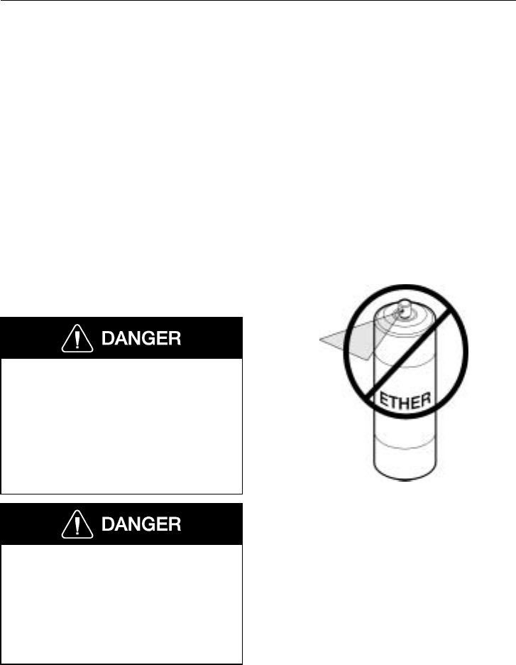
Engine Start and Operation 197
Starting the Engine
Start Procedure
NOTE! For cold weather starting, see page
202.
These starting and operating procedures
should be followed for all engines. For
more detailed information about design and
function on a non-Volvo engine, read the
Operator’s Manual from the engine manu-
facturer.
NOTE! Before starting the engine, see
“Instruments and Controls” (starting on
page 64) for detailed information on how
the gauges and telltales work.
Do not use ether or similar starting aids
in a Volvo or any other engine with start
help. The Volvo engine is equipped with
a preheater. Introduction of ether or
other combustible material in the intake
manifold could cause a fire or explosion,
resulting in severe property damage, se-
vere personal injury or death.
Never operate the starter without first
placing the transmission in neutral or
depressing the clutch pedal. Failure to
follow these instructions may result in
the unintentional movement of the vehi-
cle resulting in property damage,
personal injury or death.
W0001484
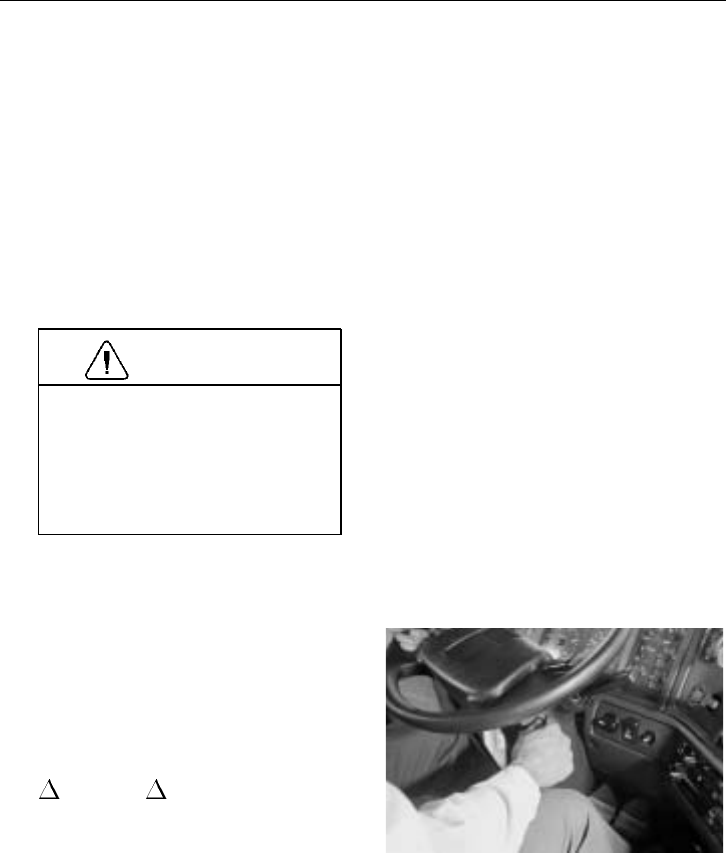
198 Engine Start and Operation
1Before starting the engine, perform the
engine pre-trip inspection and daily
maintenance checks in “Pre-Trip In-
spection and Daily Maintenance”
starting on page 28.
2Make sure the parking brakes are en-
gaged.
3Place the transmission in neutral or
depress the clutch pedal.
4
CAUTION
Do not crank the engine for more
than 30 seconds at a time; wait two
minutes after each try to allow the
starter to cool. Failure to follow
these instructions could cause
starter damage.
NOTE! Some starters are equipped
with an optional thermostat. If over-
cranking occurs, the thermostat breaks
the electrical circuit to the starter mo-
tor until the motor has cooled.
Turn on the ignition with the switch
key (see page 201 for ignition switch
information). Some telltales will light
up in a routine check that shows that
bulbs and systems are OK. The
INFO and STOP telltales will
stay on between 3 to 10 seconds.
If any of the telltales stay lit, that
function of the vehicle may not be op-
erable. Do not operate the vehicle until
the problem is repaired.
W3000753
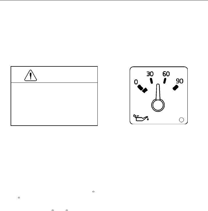
Engine Start and Operation 199
5Turn the key on to the start position.
Release key as soon as the engine has
started. For the Volvo engine, the pre-
heater can be engaged to help starting
in cold temperatures. For switch func-
tion, see page 201.
6
CAUTION
If at start-up, or thereafter, the oil
pressure gauge indicates any drop
in oil pressure, the engine must be
shut down immediately. Failure to
stop the engine may cause major
engine damage.
When the engine has started, it takes a
while to send lubricating oil to all
bearings and shafts, and between pis-
tons and liners. Wait for the oil
pressure gauge to settle at a normal
level, then bring engine speed up grad-
ually. Increase speed as it warms up.
Check all gauges during warm-up.
7During warm-up, apply load gradually
until the oil temperature reaches 140 F
(60 C). To start a loaded vehicle, the
minimum coolant temperature must be
approximately 120 F (50 C).
W3000902

200 Engine Start and Operation
Stopping the Engine
Allow the engine to slow down and idle for
3 to 5 minutes before shutting it off. This
allows the turbo to slow down and the
cooling system to dissipate the engine heat.
Switch the engine off by turning the igni-
tion key to the O, or OFF, position.
CAUTION
Shutting off an engine immediately after
high speed or full load operation can
damage the turbo and cause heat stress
in the engine. Always let the engine idle
for 3 to 5 minutes before shutting it off.
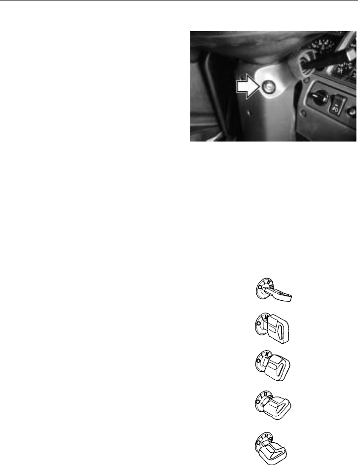
Engine Start and Operation 201
Ignition Switch
The ignition switch is located on the right
side of the steering column just under the
steering wheel. Standard equipment is a
normal ignition switch.
A steering wheel lock is available as an op-
tion. When the key is removed it actuates a
detente pin that prevents the steering shaft
from turning.
NOTE! The vehicle is delivered with 2
identical keys. If more keys are needed,
order them through your Volvo Truck au-
thorized dealer. The keys are laser cut
and require a special machine for copy-
ing, available through your Volvo Truck
dealer. Record the key code and keep in
a secure place. A new key can be made,
using the key code, if the keys are lost.
W3000976
The ignition positions are:
OOff
IRadio, Accessories
II Drive
II 1/2 Preheat (Volvo engine only)
III Start
The ignition switch has a restart inhibitor
locking out the start position after one try,
which means that the key must be turned
back to Obefore a new attempt at starting
can be made.
The key can only be removed when in the
Oor Off position.
For full starting instructions, see page 198.
W3001302
202 Engine Start and Operation
Cold Weather Start and Operation
Volvo Engine Cold Start
NOTE! These cold start instructions are for
Volvo engines only. For other engine
makes, see the manufacturer’s handbook.
Do not use ether or similar starting aids
in a Volvo or any other engine with start
help. The Volvo engine is equipped with
a preheater. Introduction of ether or
other combustible material in the intake
manifold could cause a fire or explosion,
resulting in severe property damage, se-
vere personal injury or death.
NOTE! Volvo engines have a unique cold
start feature. Depending on the ambient
temperature, the engine cranks two to four
turns without injecting fuel. This provides
cleaner combustion at start-up and pro-
motes longer engine life.
To avoid excessive exhaust smoke when
starting a cold engine, the intake air should
be warmed up by using the preheater.
Turn the ignition key to the preheat posi-
tion and hold momentarily to engage the
preheater. It remains engaged and will light
the preheater telltale between 0 and 50 sec-
onds, depending on the engine coolant
temperature.
T3008841

Engine Start and Operation 203
Coolant
Temperature Preheater
Engagement
Time (seconds)
Above +120 F (50 C) 0
Above +50 F (10 C) 0
Between +4 F (-15 C)
and +50 F (10 C) 25 ± 2 to 50 ± 2
Below +4 F (-15 C) 50
When the engine has started, the preheater
may be re-engaged to assist in faster engine
warm-up. To re-engage, turn the key to the
preheat position and the preheater will en-
gage. The starter will not engage as the
start position is locked out.
Engines Without Preheater
Engines not equipped may, depending on
coolant temperature, take longer to start. If
this should happen, do not release the igni-
tion key until the engine has started (while
still observing the 30 second maximum
cranking time).
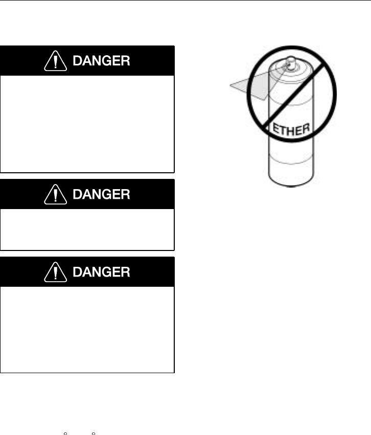
204 Engine Start and Operation
Ether Start
Do not use ether or similar starting aids
in a Volvo or any other engine with start
help. The Volvo engine is equipped with
a preheater. Introduction of ether or
other combustible material in the intake
manifold could cause a fire or explosion,
resulting in severe property damage, se-
vere personal injury or death.
Do not breathe the ether fumes. Breath-
ing ether fumes could result in personal
injury or death.
If using a cold start system, make sure
to read and follow the manufacturer’s
instructions regarding its use, handling
and storage. Many starting fluids are
sold in capsules or pressure cans and
improper usage can be dangerous, result-
ing in personal injury or death.
Ether allows combustion with lower cylin-
der temperatures. A hand-held spray can for
injecting ether through the engine air intake
system will usually provide quick starting
to as low as -10 F (-23 C). Below this tem-
perature, a permanently installed system for
injecting a combustible vapor directly into
the intake manifold is necessary.
Only inject ether vapors when the engine is
cranking. Use it sparingly! Excessive ether
use can cause piston and ring damage.
W0001484

Engine Start and Operation 205
Cold Weather Operation
If the engine is in good mechanical condi-
tion and the necessary preparations are
taken for cold weather operation, ordinary
cold weather will not cause difficulty in
starting or loss of efficiency.
Cold weather operation does require
changes in operating practices, maintenance
procedures, lubrication and fuel. Additions
to the vehicle, such as heated fuel filters,
fuel tank heater, engine block heater, win-
terfront, etc. can make winter operation
easier. Contact your Volvo Truck dealer for
the correct accessories and information
about installation.
If satisfactory engine temperature is not
maintained, increased engine wear will
result in higher maintenance cost. Acces-
sories should be designed to be easily
disconnected when switching to driving in
warmer weather so they do not affect the
operation of the engine.
For cold weather operation follow these
recommendations:
•When starting the engine in tempera-
tures below 32 F(0C), use engine
lubricants of lower viscosity. See the
“Operator’s Manual, Maintenance and
Engine” for more information.
•When the temperature is below freez-
ing, make sure the concentration of
antifreeze in the coolant is sufficient to
prevent freezing. See “Operator’s
Manual, Maintenance and Engine” for
more information.

206 Engine Start and Operation
•During cold weather, give more atten-
tion to the condition of the batteries.
Test them frequently to ensure suffi-
cient power for starting. A dead
battery may freeze.
•Fuel cloud point is the temperature at
which wax crystals become visible,
which is generally above the pour
point of the fuel. To keep the fuel fil-
ter elements from plugging with wax
crystals, the cloud point should be no
higher than the lowest ambient temper-
ature at which the engine must start.
To prevent wear and possible damage to the
engine when it is cold, gradually bring it up
to operating temperature before operating at
high engine speeds or full load. After start-
ing and before moving the vehicle, run the
engine at 800 to 1000 r/min for 3 to 5 min-
utes. Operate at partial engine load until the
coolant temperature reaches 165 F (75 C).
Engine Block Heater (option)
An electric engine block heater can be in-
stalled for keeping the coolant hot when the
vehicle is parked. The heater is mounted
through the side of the engine block with
the heater coils in the coolant jacket. The
heater does not interfere with normal oper-
ation and can be permanently installed.
The heater runs on 120 V and has an easily
accessible plug, located under the driver
side door. The plug will hook up to a nor-
mal extension cable.
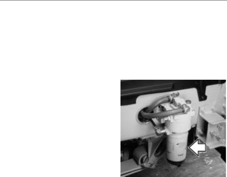
Engine Start and Operation 207
Oil Pan Heater (option)
Oil pan heaters aid low temperature starting
by improving oil flow to critical parts in
the engine. This helps prevent engine wear.
They are similar to block heaters and are
wired into the same plug as the engine
coolant heater.
Fuel Heater Filter (option)
If running in very cold weather, a heated
fuel filter should be added. A number of
different fuel heaters are available as op-
tions. They are electrically heated and
regulated by a thermostat. They are typi-
cally built into the primary fuel filter
housing.
W2001067
Fuel Tank Heater (option)
An in-tank fuel heater is also available. In-
tank heaters use hot engine coolant to
warm the fuel. This prevents wax formation
in the fuel during cold season operation.
These heaters are thermostatically con-
trolled and will automatically raise the fuel
temperature to an optimum level.
208 Engine Start and Operation
Winterfront
Volvo Trucks North America, Inc. does not
recommend the use of winterfronts, shutters
or any other shield in front of the grille or
radiator package under normal circum-
stances.
Today’s electronically controlled engines
are designed to operate in cold tempera-
tures without a winterfront. These devices,
if not used properly, can cause higher ex-
haust temperatures, power loss, excessive
fan usage, failure of the charge-air-cooler
and a reduction in fuel economy.
Winterfronts are properly used in the win-
tertime during very cold weather with
sustained temperatures below -15 F
(-25 C). In these cases, coolant and inlet
manifold temperatures must also be care-
fully monitored and controlled.
CAUTION
Failure to remove the winterfront when
temperatures go above -15 F (-25 C)
could cause severe damage to engine,
charge-air-cooler and/or loss of fuel
economy.
If a winterfront is used, it must conform to
these specifications:
•The grille coverage should be such
that airflow through to the charge-air-
cooler is at a uniform rate over the
entire area. This means that a single,
small opening in the winterfront is not
acceptable.
•Air passage must be distributed evenly
across the grille and no more than
85% can be covered.
Please see your local Volvo Trucks dealer
for Volvo recommended winterfronts.
NOTE! If there is engine or related dam-
age that can be traced to an improperly
used winterfront, the warranty is no longer
valid for those parts.

Engine Start and Operation 209
Engine Operation
General
Proper operation, driving techniques and
maintenance are key factors in obtaining
the maximum life and economy from a
modern turbocharged diesel engine. This
section has operational information about
the components that make up the engine.
For the best operation economy, see “Fuel
Economy” page 190.
When changing gears, avoid lugging to
extend engine life. When the engine is op-
erating at full throttle and maximum
governed speed cannot be reached or main-
tained, the engine is lugging. When
approaching a hill requiring more power, it
is necessary to downshift the transmission
as the vehicle goes into the grade. Acceler-
ating to the governed engine speed will
give additional power at approximately the
same road speed. For shifting instructions,
see the transmission manufacturer’s Opera-
tor’s Manual.
Always start moving the load in a gear low
enough so that the engine can be acceler-
ated to the governed speed. Then shift to
the next gear as the engine decelerates. For
loaded vehicles, do not skip a gear or lug
the engine while getting up to cruising
speed. For empty or light loads, it is per-
missible to skip gears.
When operating on a level highway or at
cruising speed, hold the engine speed at ap-
proximately 75 to 85 percent of governed
speed (1400 to 1600 r/min for large dis-
placement engines) to achieve power and
economical fuel consumption.

210 Engine Start and Operation
The operator should understand the operat-
ing characteristics of the engine the vehicle
is equipped with. Modern diesel engines
have maximum torques at much lower en-
gine speeds than in the past. As such, these
engines are designed to perform satisfacto-
rily at a lower speed. New transmissions
with wide ratio steps between gears de-
mand the use of these engines.
Excessive exhaust smoke may be due to the
type of fuel used, a restricted air cleaner, a
malfunctioning fuel system or the way the
vehicle is operated. Shift gears and increase
or decrease the engine speed as necessary
to obtain the engine speed/transmission
gear combination which will prevent smok-
ing. Excessive smoke indicates wasted fuel
which creates carbon deposits in the engine
and turbocharger. This causes excessive en-
gine wear and oil consumption. Excessive
smoke not only polutes the atmosphere but
can also cause shortened exhaust system
life.
Engine Break-In
Engines used in the VHD-series are run on
dynamometers before being shipped from
the manufacturer. In most applications, the
engine can be put to work immediately, but
the operator should be extra observant of
the operating conditions shown on the
gauges during the initial 100 hours or 3000
miles (5000 km).
A more frequent check of the engine com-
partment for fluid leaks, fluid levels and
fastener tightness is also recommended dur-
ing the initial period.
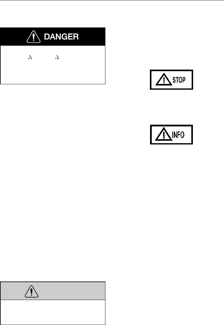
Engine Start and Operation 211
Engine Shut-Down System
Failure to take the necessary precautions
when the INFO or STOP telltales
are on, can ultimately result in automatic
engine shut-down and the loss of power
steering. Vehicle crash can occur.
The engine shut-down system will automat-
ically derate or stop the engine when one
or more of the systems listed below reaches
a critical stage:
•High Coolant Temperature
•Low Oil Pressure
•Low Coolant Level
Derate and shut-down functions may be ap-
plied differently, or added to, depending on
the engine manufacturer. See the engine op-
erator’s manual for more information.
When the shut-down is activated, the
telltales come on and the buzzer is also ac-
tivated. From that time it will take 30
seconds before the engine shuts down. In
this time period, find a safe place to pull
off of the road.
After the engine has been shut down by the
system, the override will allow a restart of
the engine for a period of 30 seconds. This
is so that the vehicle may be pulled off of
the road, if necessary. The alarm will re-
main activated until repairs have been made
to correct the problem.
WARNING
The operator should not continually
override the system as this can cause se-
rious damage to the vehicle’s engine.
T3008861
T3008860
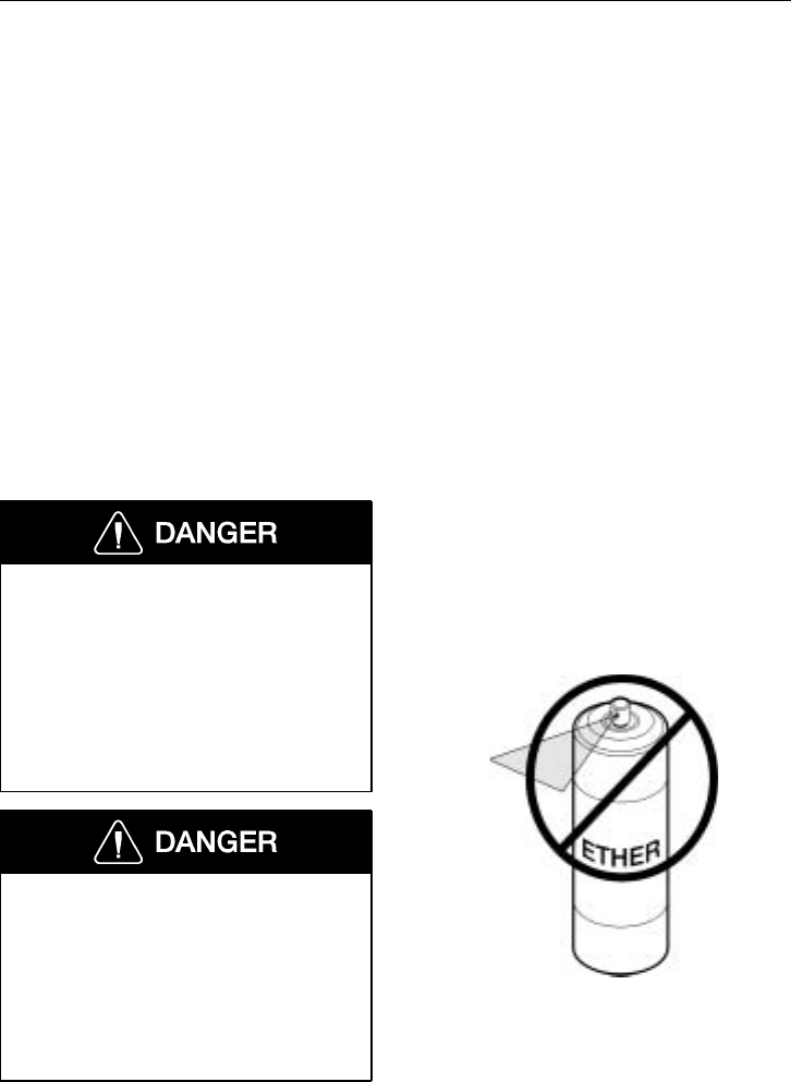
212 Engine Start and Operation
Engine Overspeed
This vehicle is equipped with a diesel en-
gine and should not be operated in an area
with a concentration of hydrocarbon vapors
(for example gasoline or diesel fuel fumes).
Be especially cautious of low-lying or
closed-in areas. The vapors may be drawn
into the engine through the air intake and
cause the engine to overspeed. Hot carbon
and other sparks may come from the ex-
haust system, and cause an explosion and
fire.
If the vehicle is in an area where hydrocar-
bon vapors may be present, shut the engine
off immediately if any abnormalities are
experienced. Do not leave it unattended.
The diesel engine will operate on any
fuel which enters the cylinder, whether it
is from the injectors or from the air in-
take system. Therefore, if any solvent is
used to flush out the air cleaner element,
the engine may overspeed during
start-up. Engine damage and severe
injury and/or death from burns or explo-
sion can occur.
Do not use ether or similar starting aids
in a Volvo or any other engine with start
help. The Volvo engine is equipped with
a preheater. Introduction of ether or
other combustible material in the intake
manifold could cause a fire or explosion,
resulting in severe property damage, se-
vere personal injury or death.
W0001484

Engine Start and Operation 213
Idling
All engines in the VHD models are elec-
tronically governed engines. The idle speed
is pre-programmed from the manufacturer.
Low idle speed is adjustable within certain
limits (for most engines between 600 to 750
r/min). See page 214 for more information.
The common belief that idling a diesel en-
gine causes no engine damage is wrong.
Idling produces sulfuric acid, which breaks
down the oil and eats into bearings, rings,
valve stems and engine surfaces.
NOTE! Avoid excessive idling. If the vehi-
cle is parked for more than 5 minutes, stop
the engine. An engine can burn from 0.75
to 1.5 gallons (3 to 5.5 liters) of fuel per
hour while idling. During long engine
idling periods, the engine coolant tempera-
ture may fall below the normal operating
range*. Incomplete combustion of fuel dur-
ing the warm-up period can cause dilution
of the oil in the crankcase, formation of
lacquer or gummy deposits on the valves,
pistons and rings, and rapid accumulation
of sludge in the engine.
*Volvo engines are equipped with a
warmholding device (EPG = Exhaust Pres-
sure Governor) to keep engine to normal
operating temperature to prevent incom-
plete combustion, even at idle.
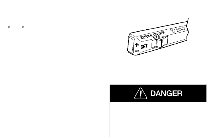
214 Engine Start and Operation
Low Idle Adjustment
If the engine coolant temperature is above
122 F (50 C), the vehicle is stationary (en-
gine running; accelerator released; parking
brake on) and the PTO not engaged, the en-
gine low idle speed can be adjusted with
the use of the cruise control function.
1 Set the cruise control switch to the
ON position.
2 Depress the foot brake pedal. Hold it
down during the entire procedure.
3 Move the cruise control switch to the
RESUME position and hold it there
for four seconds. Release the switch.
The engine speed will drop to the de-
fault low idle.
4 The idle speed is adjusted up with the
SET+ switch. Each time the SET+
switch is pressed momentarily, idle
speed will increase approx. 10 r/min
(the speed cannot be increased above
the maximum allowed by the engine
manufacturer).
5 The idle speed is adjusted down with
the SET- switch. Each time the SET-
switch is pressed momentarily, the idle
speed will decrease approx. 10 r/min.
(the speed cannot be adjusted below
the low idle set by the engine manu-
facturer). By continuously pressing the
switch, engine speed will ramp up
(SET+) or down (SET-).
6 When the desired engine idle speed is
reached, push and hold the SET and
move the cruise control switch to the
RESUME position at the same time
and hold them in position for four sec-
onds. Release the switches.
7 Release the brake pedal to set the new
idle speed. If an error was made dur-
ing the adjustment procedure, the
default idle speed will be maintained.
W3002499
Before setting the idle, apply the parking
brakes and place the transmission in
neutral. Failure to do so can result in un-
expected vehicle movement and can
cause serious personal injury or death.

Engine Start and Operation 215
Idle Shutdown Timer
The idle shutdown timer can be pro-
grammed to shut the engine down after a
specific engine idling time. The program
can not be changed by the operator but
requires a special tool (Pro-Link) that con-
nects to the engine electronic control unit.
This is available at your Volvo Truck dealer.
The time can be set to these time intervals:
Volvo 1 to 40 minutes
Cummins 1 to 100 minutes
Detroit 2 to 100 minutes
The engine will shut down at the set time
under the following conditions:
•Vehicle speed is 0.
•Engine is running at idle speed.
•Coolant temperature is above
113 F (45 C).
•Parking brake is applied.
These are the standard choices when the
vehicle is delivered. For other customer
adaptation choices, contact your Volvo
Truck dealer for more information.
216 Engine Start and Operation
Uphill Operation
For best performance, allow engine speed
to reach the bottom of the rated torque
range before downshifting. Continue to
downshift in this manner until a gear is
reached that will maintain the desired
speed. Continue to operate at the rated
torque if the vehicle will make it to the top
without a downshift. Begin upshifting as
the grade of the hill decreases and the en-
gine begins to accelerate above 1600 r/min.
Driving this way will give the best fuel
economy and performance.
NOTE! Allowing the engine to lug down
to the end of maximum torque range is per-
missible if the vehicle is cresting the top of
a hill. However, extended operation at en-
gine speeds below the maximum torque
range (usually 1100 to 1200 r/min) will
raise exhaust temperature and cylinder pres-
sure. This can lead to reduced engine life.
Downhill Operation
CAUTION
Do not exceed engine manufacturer’s
recommended maximum engine speed.
Engine damage can occur. If equipped
with an engine or exhaust brake, do not
exceed 2300 r/min.
On a downgrade, do not coast with the
clutch pedal depressed or the transmission
in neutral. Select a gear that does not allow
the engine speed to exceed the engine
manufacturer’s maximum engine speed rec-
ommendation. Use the engine or exhaust
brake and/or the service brakes to control
the vehicle speed. A simple rule is to select
the same gear used to go up the grade.

Engine Start and Operation 217
High Altitude Operation
Engines lose power when operated at high
altitude because the air is too thin to allow
burning as much fuel as at sea level. For
naturally aspirated engines, this loss is
about 3 percent per 1000 feet (300 m) in-
crease in altitude above sea level. Most
turbocharged engines are rated for higher
altitudes and will not lose as much power
as a naturally aspirated engine.
An engine will produce excessive exhaust
smoke at high altitude unless a lower gear
is used. Shift gears as needed to avoid ex-
cessive exhaust smoke.
Closely monitor the gauges during high al-
titude operation. The thinner ambient air
reduces the efficiency of the engine cooling
system. Engine overheat or cylinder dam-
age could occur if the engine is operated at
full load for extended periods at high alti-
tudes in hot weather. Downshift and reduce
vehicle speed to reduce engine load when
driving on long grades in these conditions.
This will help keep engine air intake mani-
fold and coolant temperatures within safe
limits.
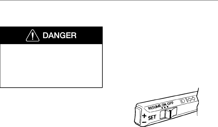
218 Engine Start and Operation
Cruise Control
Do not use the cruise control in heavy
traffic, with ice/snow on the road or dur-
ing other unfavorable conditions. This
may lead to a loss of vehicle control,
causing a vehicle crash and can result in
personal injury or death.
Engaging
The cruise control switches are located on
the turn signal lever.
To engage and set desired speed:
1 Set the cruise control switch to ON.
2 When the desired vehicle speed has
been reached, momentarily press in
the SET+ or SET- switch on the end
of the lever.
3 If the speed needs to be increased,
press the SET+ switch. The vehicle
speed will increase as long as the
SET+ switch is pressed (speed will not
increase above the maximum pro-
grammed speed). Release when the
desired speed has been reached.
4 If the speed needs to be decreased,
press the SET- switch. The vehicle
speed will decrease as long as the
SET- switch is pressed (speed will not
decrease below the minimum pro-
grammed speed). Release when the
desired speed has been reached.
NOTE! The cruise control cannot be en-
gaged at speeds below approximately
30 mph (45 km/h) and engine speed below
approximately 1000 r/min.
W3002499
Engine Start and Operation 219
Disengaging
The cruise control is disengaged if the
brake or clutch pedal is depressed, or if the
cruise control switch is set to OFF. If the
ignition key is turned back to the acces-
sories position (R), the cruise control
system will automatically be disengaged.
Resuming Vehicle Speed
The previously selected cruise speed is re-
tained in the memory. When the cruise
control switch is pushed to the RESUME
position, the vehicle resumes the previously
set speed (provided vehicle speed exceeds
approximately 10 mph (15 km/h) when the
switch is pressed).
Acceleration
Momentary acceleration (such as for pass-
ing another vehicle) does not interrupt
cruise control operation. After passing, re-
lease accelerator and let the vehicle slow to
cruise control speed. The previously set
speed will then be maintained without hav-
ing to set the switch to RESUME.
CAUTION
On vehicles equipped with Eaton VO-
RAD SmartCruise, cruise control is
disengaged in the event the SmartCruise
system fails to operate. You must stop
the truck, turn the ignition off and on,
and activate the control twice in order
for the cruise control to operate.
NOTE! Read the Eaton VORAD Collision
Warning System Driver Reference Manual
before taking the vehicle out on the road.
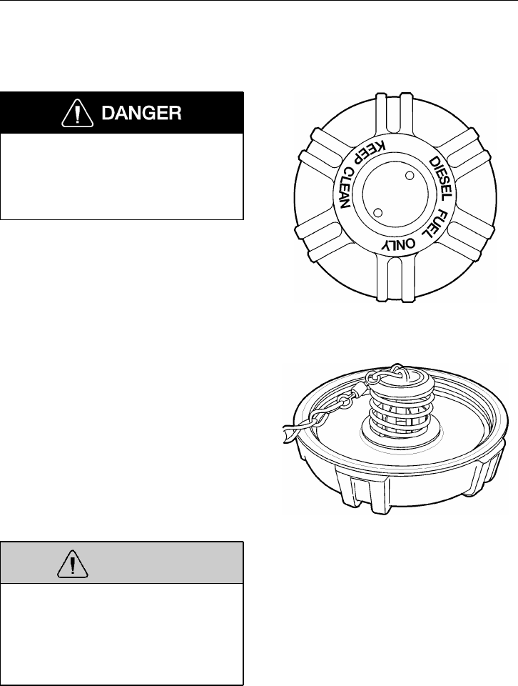
220 Engine Start and Operation
Fuel Tank(s)
Tank Cap
Do not remove the fuel tank cap near an
open flame. Diesel fuel vapors are com-
bustible and can cause an explosion or
fire, resulting in severe personal injury
or death.
The fuel tank caps have a pressure and a
thermal relief function built into the cap.
These functions are designed to avoid fuel
spills in the event of an accident. The pres-
sure relief function of the safety venting
system has a crack pressure high enough to
retain fuel in the tank regardless of the ori-
entation of the vehicle [5 to 8 psi (35 to 55
kPa)].
The thermal relief feature is large enough
to limit tank pressure to a safe level even
when the remaining fuel is boiling in the
tank, but not so large as to dump fuel un-
neccessarily. The thermal relief should
respond as much as possible to fuel tem-
perature rather than flame temperature.
These features are also available on the op-
tional lockable fuel tank cap.
WARNING
Only replace the cap with a cap contain-
ing the same features described above.
Unneccessary fuel spills leading to in-
creased fire hazard may be the result of
using a cap without the pressure and
thermal relief mechanisms.
In the case the cap is lost, it must be re-
placed with a cap containing the same
features.
W2003143
W2003144
Engine Start and Operation 221
Fueling
Air is always present inside the fuel tanks,
entering mainly through the tank ventila-
tion. With the air being heated up and
cooled down, condensation is formed and
water is mixed in the fuel. To avoid con-
densation when the vehicle is parked for
longer periods, fill the tanks up to 95% of
capacity. Do not fill more than that, as the
fuel needs to have room for expansion dur-
ing the heat of the day.
Do not carry extra fuel containers in the
cab. Fuel containers, full or empty, may
leak, explode or give added fuel to a fire.
Failure to follow this precaution may
lead to serious personal injury or death.
Do not smoke while fueling the vehicle.
The glow from the cigarette can ignite
the diesel fuel, causing an explosion re-
sulting in serious personal injury or
death.
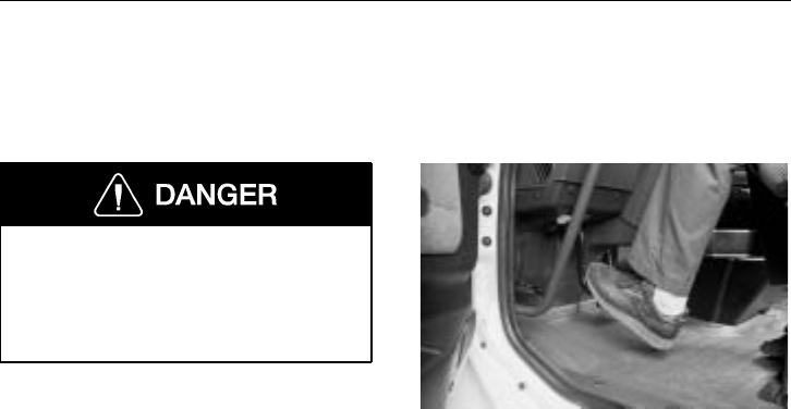
222 Clutch and Transmission
Clutch
General
Before starting the engine, set the park-
ing brakes and place the transmission in
neutral. Failure to do so can result in un-
expected vehicle movement and can
cause serious personal injury and death.
Do not allow the clutch to slip excessively.
This would cause excessive heat to be gen-
erated and the clutch will be damaged and
bring on premature failure. As soon as the
vehicle is moving, remove the foot from
the pedal for complete clutch engagement.
Once the clutch is fully engaged, heat and
wear does not affect it.
Do not shock load the drive line through
rapid engagement of the clutch. Extreme
care should be taken when driving heavy
loads up hills. Always use the lowest gear
when starting out under adverse conditions.
When operating a vehicle equipped with a
clutch brake, the clutch pedal should not be
depressed more than halfway to the floor
while shifting, except when the vehicle is
at a stop. To re-enter the low gear from
neutral or reverse, or to enter reverse gear
from neutral or low, the clutch should be
depressed all the way to engage the clutch
brake. This stops the rotation of the trans-
mission input shaft and provides an easy,
quiet gear engagement.
W4000760
Brakes 223
Brakes
Brake Safety Information
Do not inspect or adjust parts or compo-
nents in the brake system without setting
the parking brake, placing the transmis-
sion in neutral and securely chocking the
wheels. If the vehicle is not secured to
prevent uncontrolled vehicle movement,
it could roll and cause severe personal
injury or death.
Do not use replacement parts anywhere
in the brake system unless it conforms
exactly to original specifications. A non-
conforming part in your vehicle’s brake
system could cause a malfunction, lead-
ing to loss of control of the vehicle
resulting in severe personal injury or
death.
Do not ride the brakes going down steep
hills. The brakes could overheat and lose
their effectiveness. Always choose a low
gear before going down the grade and
reduce speed to help control vehicle
speed. Losing the brakes going downhill
can lead to an accident causing serious
personal injury or death.
Do not operate the vehicle when there is
a malfunction in the compressed air sys-
tem. An air brake system with leaks or
other malfunctions may prevent the
brake system from operating properly.
The vehicle should not be operated until
the system is repaired and all brake cir-
cuits are working properly. Failure to
repair the system can lead to loss of
control of the vehicle resulting in severe
personal injury or death.
The brake system is a critical vehicle
safety system. For your safety and for
those around you, follow the recom-
mended preventive maintenance checks.
If any problems occur, have them inves-
tigated immediately by an authorized
service facility. Failure to properly main-
tain the brake system can result in
compromised brake efficiency and may
lead to loss of control of the vehicle re-
sulting in severe personal injury or death.
Do not drive through deep water. The
brake system can be affected so the
braking efficiency is less or the brakes
pull the vehicle to the side. This could
lead to an accident leading to serious
personal injury or death.
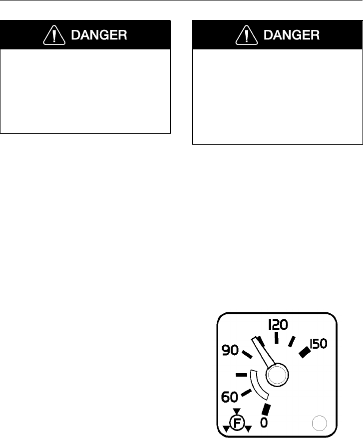
224 Brakes
Do not release the parking brake or at-
tempt to move the vehicle until brake air
pressure in both circuits is at least 100
psi (690 kPa). Failure to follow this pro-
cedure may lead to uncontrolled vehicle
movement and cause severe personal in-
jury or death.
Never release or drive a truck that has a
brake discrepancy — no matter how mi-
nor — until it has been repaired or
corrected. Failure to repair brake dis-
crepancies can result in compromised
brake efficiency and may lead to loss of
control of the vehicle resulting in severe
personal injury or death.
General
All Volvo vehicles are designed to meet or
exceed all applicable federal brake stan-
dards and regulations. They use a dual
circuit, compressed air system. It consists
of two independent brake systems that use
a single set of brake controls. Each circuit
is supplied by its own compressed air tank.
Both air tanks receive compressed air from
the same supply tank (wet tank) and are
charged with equal pressure. The two cir-
cuits are interconnected for the parking
brake system.
Air pressures in the two circuits are moni-
tored by two pressure gauges on the right
side of the instrument cluster. The primary
(rear) brake circuit gauge is marked with an
“R” within a symbol and the secondary
(front) brake circuit gauge is marked with
an “F” within a symbol. The two pointers
should register equal or nearly equal pres-
sure. By observing the gauge pointers, the
operator is forewarned in the event of a
pressure drop in either or both of the cir-
cuits. See page 85 for more information.
Before operating the vehicle, check the air
gauges which indicate air pressure. They
should not register less than 105 psi
(725 kPa). Maximum pressure at any time
should not exceed 150 psi (1035 kPa).
W3003637
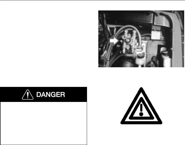
Brakes 225
Both circuits are piped into a dual brake
valve, which simultaneously applies front
and rear axle service brakes during each
brake application. In the event of a failure
in either one of the circuits, the other cir-
cuit becomes the emergency circuit for
applying the brakes.
W5000923
The Master Warning Telltale and buzzer
alerts of a dangerous situation. Air pres-
sure is low and the remaining air volume
may not be enough for repeated braking.
Failure to heed this warning can result
in loss of braking control resulting in a
vehicle accident and injury or death.
An important feature of the brake system is
that an automatic spring brake application
does not take place as a result of an air loss
in only one of the two circuits. In this case,
brake control remains in the foot brake
valve. In each air pressure gauge, there is a
warning light connected to a low pressure
switch that comes on if air pressure goes
below 60 psi (420 kPa). At the same time,
the buzzer will sound and the main warning
telltale will come on. This pressure drop
warns the operator to make a manual emer-
gency stop before an automatic emergency
stop takes place.
W3000638
Master Warning Telltale
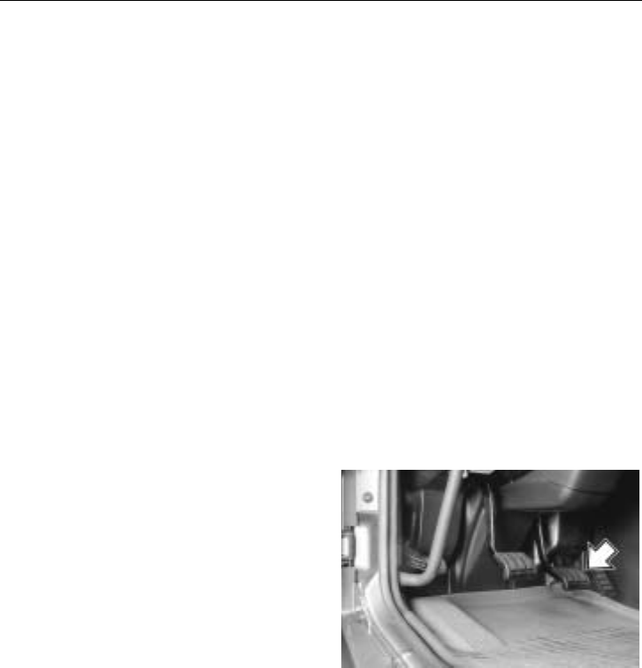
226 Brakes
Brake System Controls
The air compressor, governor, pressure reg-
ulator valve and reservoirs are control
devices. Their function is to build up,
maintain and control air pressure in the
reservoirs. This is so that pressure is held
constant between the minimum and maxi-
mum range established for air brake
operation.
The brake valve, quick release valve, brake
chambers and slack adjusters are applica-
tion devices. They distribute the air
pressure and convert its energy into the me-
chanical force necessary to apply or release
the brakes.
Foot Brake Valve
The foot brake valve is directly connected
to the brake pedal. The valve gives a pro-
gressive output against the pedal travel.
This allows better control of the pressure in
the first half of the pedal travel. In the last
half of the pedal travel, the pressure output
increase is faster.
The foot brake valve applies the service
brakes, incorporating both the primary and
secondary air systems. The primary system
controls the rear brakes and the secondary
system controls the front brakes. The foot
brake valve receives air from the com-
pressed air tanks. Air pressure is then
delivered to the wheel brake chambers as
required by the amount of pressure exerted
on the foot brake pedal. The brake chamber
force then applies the wheel brakes.
W5000920

Brakes 227
From the operator’s viewpoint, operating
the foot brake valve of a vehicle equipped
with air brakes differs very little from the
operation of a conventionally braked vehi-
cle. Because the operation of the brake
pedal requires scarcely more effort than de-
pressing the average throttle pedal, air
brakes are naturally much easier to control.
If the driver gives full attention to the fol-
lowing suggestions, a little experience will
make him/her thoroughly familiar with the
air-controlled braking of this vehicle.
Failure to observe these precautions can
result in loss of vehicle control and seri-
ous personal injury or death can occur.
1 The best possible stop will be made
when the first brake application is as
firm as the speed and road condition
permit. Then, ease off as the speed is
reduced. Never apply the brakes
lightly at first and increase the pres-
sure as the speed diminishes.
2 Do not fan the brake pedal. Fanning
gives poor brake performance and
wastes air.
3 The air brake is designed so that when
the brake pedal is fully depressed, an
emergency application results. This
application should be made only in an
emergency situation.

228 Brakes
4 In making a stop or a slow-down, al-
low the transmission to remain in gear
with the throttle closed, disengaging
the clutch only when engine idling
speed is reached.
5 When parking the vehicle, place the
transmission in neutral and set the
parking brake before shutting down
the engine.
6 When descending a long grade, do not
use the service brakes too long or too
often. The brakes may overheat and
lose their effectiveness.
7 Before descending a steep grade, the
transmission should be shifted into a
lower gear and the vehicle speed re-
duced. Other speed retardation devices
should also be used if available (en-
gine brakes, retarders or trailer hand
control valves).
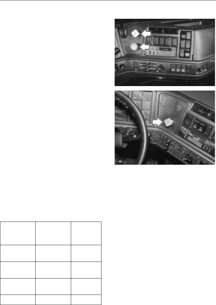
Brakes 229
Parking Brake/Trailer Supply Valves
Trucks/Tractors may have two air control
valves on the instrument panel:
•Trailer Supply (red octagonal knob)
•System Park (yellow diamond knob)
The two air control valves are intercon-
nected and interacting. The System Park
valve supplies and controls the Trailer Air
Supply valve.
The System Park valve knob (yellow)
should be pushed in first, after sufficient air
pressure is built up (apply foot brake to pre-
vent vehicle from rolling). The Trailer Air
Supply valve knob may then be pushed in.
The Trailer Air Supply valve knob and Sys-
tem Park valve knob will automatically pop
out if the system pressure (both front and
rear circuits) drops to 25 to 35 psi (170 to
240 kPa). The tractor protection valve will
then close, the tractor spring brakes will
apply and the trailer emergency system will
be activated.
On vehicles equipped with the standard two
valve system, the operation of one valve to-
gether with the other permits the operator
to select the desired functions described be-
low:
Red Valve
(Trailer Air
Supply)
Yellow
Valve (Sys-
tem Park)
Function
(Mode)
Out Out System
Park
In Out Trailer
Charge
In In Normal
Running
Out In Bobtail
W5000924
W5001138
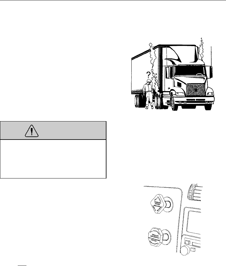
230 Brakes
Parking Brake Release
VHD models have engines equipped with
engine electronic control units (EECU).
These have two features that may impact
the brake system. One is the anti-stall de-
vice in the EECU which senses torque
demand and automatically controls the en-
gine to compensate and maintain speed. On
tractors equipped with parking brakes on
only one axle, the anti-stall device keeps
the engine from stalling, allowing the driver
to pull away with the brakes dragging. This
may result in overheated brakes and dam-
aged wheel hubs.
WARNING
Continual dragging of the brakes will
cause brakes to overheat. This may lead
to wheel end fire. To avoid overheating,
make sure both parking brake knobs are
pushed in before driving off.
‘
W5001114
If both the yellow and the red knobs are
pulled out, the combined force of the two
trailer axles and the tractor drive axle is
sufficient to stall the engine. However, if
the yellow knob is pulled out and the red
knob is pushed in, a condition is created
where the trailer parking brakes are not ap-
plied and only the single drive axle brakes
are applied. In this condition, the vehicle
can be driven away. Therefore, it is very
important that the driver makes sure the
yellow and the red knobs are pushed all the
way in before driving the vehicle.
W5001116
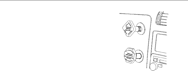
Brakes 231
There is also an engine shut-down device
in the EECU that shuts the engine down af-
ter a pre-programmed time in order to save
fuel. This is activated when the yellow
parking brake knob is pulled out. There-
fore, some drivers park and release the
parking brakes using only the red knob to
keep the engine running. It is then easily
overlooked that in a vehicle parked with
both the yellow and red knobs activated,
only the red knob is pushed in by habit. W5001117
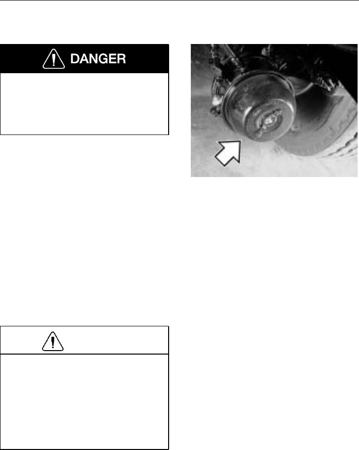
232 Brakes
Spring Brake For Parking
Never leave the vehicle without being
certain the parking brakes are set or that
other precautions are taken to prevent the
vehicle from rolling. Failure to do so can
result in serious personal injury or death.
The parking brake mechanism uses spring
pressure as a separate power medium to ap-
ply the service brakes on the driving axles.
The parking brake is released by the same
compressed air source used to apply the
service brakes. Since this brake is released
by air pressure, the system must be charged
to at least 60 psi (420 kPa) before the park-
ing brake may be released.
The parking brake spring tension is suffi-
cient to hold a fully loaded vehicle on
maximum grades permitted on modern
highways, provided the brake drums and
linings are in good condition and the brakes
are properly adjusted.
CAUTION
Do not use the spring parking brakes if
the service brakes are hot, such as after
descending a steep grade. Also, do not
use the spring parking brakes during
freezing temperatures if the wheel
brakes are wet. To do so could damage
the brakes, if hot, or may cause them to
freeze during cold weather.
If the brakes are wet, drive the vehicle in
low gear and lightly apply the brakes to
heat and dry them. Allow hot brakes to
cool before using the parking spring brakes.
W5000643
Brakes 233
There are several ways to determine if the
parking brakes have been set. By pulling
out the yellow knob:
•An audible rush of air will be heard
when the parking brake knob is pulled.
The air exhausts from the park brake
valve itself and from the spring brake
chambers on the rear axle(s).
•A black ring around the base of the
yellow control knob will be seen.
•The engine will stall if an attempt is
made to set the vehicle in motion.
•There will be a fluctuation in the air
pressure gauge needles.
•You will not be able to pull the knob
out any further.
Do not attempt in any way to disassem-
ble or tamper with the spring brake
chamber. The force stored in the spring,
if suddenly released, can cause serious
personal injury or death.
Do not apply the parking brake while
the vehicle is moving. The rear wheels
may lock up causing loss of vehicle con-
trol leading to an accident with severe
personal injury or death.

234 Brakes
Trailer Brake Hand Control
The trailer hand brake control is not a
parking brake valve and must not be
used as one. This brake is not designed
to hold the vehicle stationary. Failure to
follow these instructions can result in the
unintentional movement of the vehicle
and may cause personal injury or death.
The hand control valve for the trailer
brakes engages the trailer brakes indepen-
dently from the vehicle brakes. The valve
can be fully or partially engaged but in any
partial position it will be overridden by a
full application of the foot brake valve.
To supply air to the trailer brakes to slow
the trailer down, pull the valve handle
down. The farther the handle is pulled
down, the more air pressure is applied to
the trailer brakes. Releasing the self-
returning handle releases the trailer brakes.
W5001035
Air Tanks
WARNING
When draining the air tanks, do not look
into the area of the draining air. Dirt or
sludge particles may be in the air stream
and could cause eye injury.
Air tanks should be drained daily. Make
sure the drain cocks close properly after
draining. Empty moisture from air tanks by
pulling the drain valve wire. The tanks
should be checked for condensation fluid
even if an automatic drain valve is installed.
W5001203

Brakes 235
The “121” Brake Standard
This manual refers occasionally to “121”
brakes. Although some operators believe
“121” only applies to vehicles equipped
with anti-lock devices, the “121” standard
applies to all vehicles that are capable of
on-highway operation.
The “121” is a Federal requirement also
covering alterations or changes to parts or
systems related to the “121” standard once
the vehicle has been placed in service. The
owner and operator should be aware that it
is a violation for any repair facility to make
any part or component inoperative when it
is required for “121” compliance.
Charging Air To Another Vehicle
There are many methods which may be
used to charge the air system of another ve-
hicle. Vehicles equipped with the standard
two-valve system (trailer supply and
parking brake) must use the following pro-
cedure when using the emergency trailer air
line as an auxiliary air source, other than to
charge the trailer air reservoirs.
Before working on a vehicle, set the
parking brakes, place the transmission in
neutral, and block the wheels. Failure to
do so can result in unexpected vehicle
movement and can cause serious per-
sonal injury or death.
1 Connect the emergency trailer air line
to the auxiliary source.
2 Start the engine.

236 Brakes
Antilock Braking System (ABS)
The vehicle has a standard brake system,
equipped with an electronic speed monitor-
ing and control system, Antilock Braking
System (ABS). ABS monitors wheel speed
continuously but is not involved in control-
ling the wheel speed unless there is an
emergency. In normal braking applications,
the standard air brake system is in effect.
WARNING
For proper ABS operation, do not
change tire sizes. The size of the tires
installed during production are pro-
grammed into the electronic control unit.
Installing different sized tires could re-
sult in a reduced brake force, leading to
longer stopping distances or accidents.
There is a sensor installed in each wheel on
a monitored axle. The sensors transmit in-
formation to the electronic control unit
(ECU). The ECU interprets the signals and
calculates wheel speed, wheel retardation
and a vehicle reference speed. If the calcu-
lations indicate a wheel lock-up situation, a
signal is sent from the ECU to the appropri-
ate ABS modulator valve to reduce braking
pressure. During emergency braking, the
modulator valve alternately reduces, in-
creases or maintains air pressure in the
brake chamber to prevent wheel lock-up.
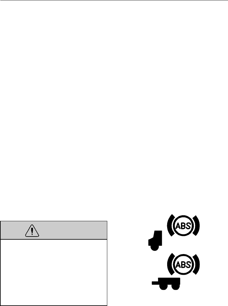
Brakes 237
During emergency or reduced-traction
stops, fully depress the foot brake pedal un-
til the vehicle comes to a safe stop. DO
NOT PUMP the brake pedal. With the
brake pedal fully depressed, the ABS will
control all wheels to provide steering con-
trol and a reduced braking distance.
Although the ABS improves vehicle control
during emergency braking situations, the
operator still has the responsibility to
change driving styles depending on the
existing traffic, road and/or weather condi-
tions. For example, the ABS cannot prevent
an accident if the driver is speeding or fol-
lowing too closely on slippery surfaces.
The ABS control unit contains a self-
testing program that is engaged each time
the ignition is turned on. The operator can
verify the testing by listening for the ABS
modulator valves actuating twice in series.
To increase the sound, hold down the foot
brake pedal when the ignition is turned on.
The self-test is not finished and the telltale
will stay on until the vehicle has started to
move. The wheel speed sensors are tested
when the vehicle starts to move. If they test
OK, the telltale will go out at approxi-
mately 7 mph (11 km/h).
WARNING
If any of the ABS telltales come on dur-
ing driving or do not go out after a short
time after turning on the ignition, take
the vehicle to a Volvo Truck dealer to
repair the ABS or brake system. The ve-
hicle can still be driven with a problem
in the ABS system. However, ABS will
not be working and the standard braking
system will be in effect. W3000905
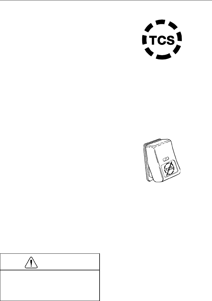
238 Brakes
Traction Control System (TCS) (option)
The Traction Control System (TCS) uses
the same wheel sensors as the ABS to de-
termine if one set of drive wheels is
spinning much more rapidly than the wheel
set on the other side. If the TCS determines
that a wheel is spinning (with vehicle speed
below 25 mph [40 km/h]), it operates the
brake system to apply some brake force to
stop the spinning wheel(s). This puts the
drive power over to the stationary wheel(s).
If vehicle speed is above 25 mph
(40 km/h), a signal is sent to the engine
ECU, which reduces the engine speed to be
consistent with vehicle speed. This action
helps reduce the amount of wheel spin and
gives the operator greater vehicle control.
W3000962
The TCS includes a switch to turn off the
function. When the switch is in the OFF
position, the TCS operates normally to in-
crease traction if the drive wheels are
spinning. When the switch is pressed once,
the TCS telltale in the instrument cluster
blinks continuously, indicating that the TCS
is in mud/snow mode.
The mud/snow mode increases available
traction on soft surfaces like snow, slush or
mud by slightly increasing the allowable
wheel spin. This prevents the wheels from
getting bogged down. The TCS will resume
normal operation when the TCS switch is
pressed again and the TCS telltale goes out
or when the ignition is turned off.
CAUTION
Do not engage the differential locks
while wheels are spinning. Serious dam-
age to the differential will occur. See
page 258 for more information.
W3001336
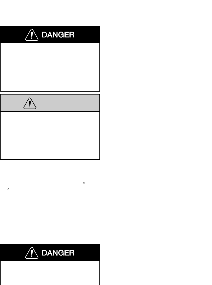
Brakes 239
Vehicle Speed Retardation Devices
When operating a tractor bobtail (with-
out a trailer) or on slippery roads, the
engine brake switch must be in the
“OFF” position. Failure to follow this
instruction can result in loss of vehicle
control and serious personal injury or
death.
WARNING
A vehicle speed retardation device (such
as a “Jake-Brake,” “C-Brake,” “Exhaust
Brake,” etc.) is not intended to bring the
vehicle to a stop. A vehicle speed retar-
dation device is only intended to retard
the vehicle speed under certain condi-
tions.
NOTE! If a Volvo engine is equipped with
a Volvo Engine Brake, the brake will not
operate with full power until the engine
coolant temperature has reached 110 F
(45 C).
NOTE! It is normal for there to be a slight
delay in the application of a vehicle speed
retardation device. When using devices of
this type, be sure to think ahead and ana-
lyze conditions in order to use the device
properly.
Failure to observe the above precautions
can result in loss of vehicle control and
serious personal injury or death.
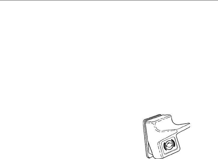
240 Brakes
Volvo Exhaust Brake
The exhaust brake is standard on the Volvo
D12 engine. It is used to reduce wear on
the brake linings. The exhaust brake is
most effective at high engine speeds (1500
to 2300 r/min). The exhaust brake is auto-
matically disengaged if the engine speed
drops to or below 1100 r/min.
The exhaust brake works by containing the
exhaust gases in the exhaust manifold,
thereby making the engine work against the
back pressure. This provides a retarding
force on the drive wheels.
The exhaust brake is operated by a two-
position switch in the right-hand switch
cluster. For the exhaust brake to function,
the following must be in effect:
•The switch is ON
•Accelerator and clutch pedals are fully
released
•Engine speed exceeds 1100 r/min
When the cruise control is engaged, the ex-
haust brake automatically engages if the
selected cruise speed is exceeded by ap-
proximately 5 mph (8 km/h). The exhaust
brake is then disengaged when the speed
has returned to approximately 3 mph (5
km/h) above selected cruise speed.
NOTE! For both exhaust and engine
brakes, use a “one gear” driving strategy
when going downhill to keep engine speed
up for effective braking (for example: up-
hill in 7th gear and downhill in 6th).
W3001324
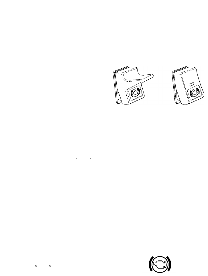
Brakes 241
Volvo Engine Brake (option)
The Volvo Engine Brake (VEB) has a
higher braking effect than the exhaust
brake. The engine brake is most effective at
high engine speeds (1500 to 2300 r/min). It
is automatically disengaged if engine speed
drops below 1100 r/min.
The engine brake function is operated by
one switch in the right hand switch cluster.
It works together with the exhaust brake to
provide two levels of braking power. The
switch has three positions: OFF, LOW and
HIGH. With the switch in position LOW,
only the exhaust brake is engaged. With the
switch in position HIGH, both the exhaust
brake and the compression brake are acti-
vated. For the engine brake to function, the
following must be in effect:
•The switch is ON
•Vehicle speed over 7.5 mph (12 km/h)
•Engine temperature over 110 F (43 C)
•Accelerator and clutch pedals are fully
released
•Engine speed over 1100 r/min
When the cruise control is engaged, the en-
gine brake automatically engages if the
selected cruise speed is exceeded by ap-
proximately 5 mph (8 km/h). The engine
brake is then disengaged when the speed
has returned to approximately 3 mph
(5 km/h) above selected cruise speed.
W3002303
Too Cold for Engine Brake (Volvo Engine Only)
Position 2 of the engine brake should not
be switched on until the engine has become
warm (over 110 F [45 C]). If position 2 is
selected and the engine is too cold, this
symbol will be shown (however, VEB is
not activated).
T3009355
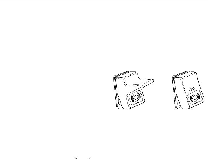
242 Brakes
Jake-Brake Or C-Brake
The Jake-Brake or C-Brake is optional
equipment for Cummins, and Detroit en-
gines. These engine brakes are similar in
operation. Three power levels are available
by engaging 2, 4, or 6 cylinders when brak-
ing (for Cummins M11, only two power
levels are available).
It is operated by two switches in the right
hand switch cluster. It works together with
the exhaust brake to provide two levels of
braking power. The left switch is the
ON/OFF switch. The desired braking power
is selected with the right switch which has
three positions: LOW, MED and HIGH (for
Cummins M11, only LOW and HIGH).
For the exhaust brake to function, the fol-
lowing must be in effect:
•The switch is ON
•Vehicle speed over 7.5 mph (12 km/h)
•Engine temperature over 110 F (43 C)
•Accelerator and clutch pedals fully re-
leased
•Engine speed exceeding 1100 r/min
When the cruise control is engaged, the ex-
haust brake automatically engages if the
selected cruise speed is exceeded by ap-
proximately 5 mph (8 km/h). The exhaust
brake is then disengaged when the speed
has returned to approximately 3 mph
(5 km/h) above the selected cruise speed.
For more information, read the Jake-Brake
or C-Brake operator’s manual.
W3002303
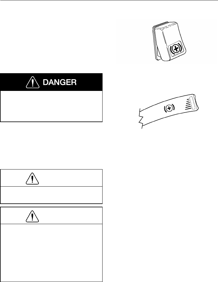
Brakes 243
Transmission Retarder
The Transmission Retarder is an option
with Allison HD and MD transmissions. It
is activated by an on/off switch in the aux-
iliary panel and is controlled by a stalk
switch mounted in front of the wiper
switch. You can set 6 different levels with
the stalk switch.
Do not use the retarder on wet or slip-
pery roads. The retarder may cause
vehicle to slide and cause an accident
which could result in injury or death.
NOTE! The retarder is automatically
disabled when the ABS (antilock brake sys-
tem) is active.
NOTE! Vehicle brake lights are always on
when transmission retarder is applied.
CAUTION
Apply the retarder only when engine is
at closed throttle.
CAUTION
Observe transmission and engine tem-
peratures. Select the lowest possible
transmission range in order to maximize
the cooling system capacity and retarda-
tion. If overheating occurs, decrease the
use of the retarder and use service
brakes instead. Check the retarder
overtemp light.
For complete warnings and instructions, re-
fer to your Allison Transmission manual.
W3004428
W3004405
244 Electrical System
Electrical System
General Safety Guidelines
WARNING
Failure to repair a malfunction in the
electrical system can result in serious
damage due to vehicle fire. Always let an
experienced electrical technician perform
repairs. Always determine the source of
the fault; do not just treat the symptoms.
WARNING
Always wear eye protection when work-
ing around batteries to prevent the risk
of injury due to contact with sulfuric
acid or an explosion.
WARNING
Before replacing a damaged fuse, turn
off all functions for that circuit. Damage
to the circuit can happen. Always re-
place fuses and circuit breakers with the
same current/amperage rating. Never
substitute a fuse with foil, wire or nails.
Increasing fuse or circuit breaker ratings
or substituting a fuse with foil, wire or
nails may result in electrical circuit
overheating and possibly fire.
CAUTION
Attempting to work on electronic com-
ponents without proper equipment can
damage internal parts with static elec-
tricity.
CAUTION
Electronic circuits and components are
designed to sense voltage differences
smaller than 1 volt. While static electric-
ity is not normally dangerous to humans,
it can seriously damage electronic cir-
cuits and components. Circuit boards
mounted in the instrument cluster, for
example, may not fail immediately after
being hit with a static discharge. Rather,
they may work for a while and then fail
for no apparent reason. Therefore, al-
ways work with proper grounding straps
and antistatic mats around electric com-
ponents.
CAUTION
Today’s vehicles contain a high number
of electronic devices. It is very impor-
tant to exercise caution when working
on a modern electrical system, charging
batteries or jump starting the engine. To
minimize the risk of any damage to the
electronic components, follow the proce-
dures below when work is being done to
the electrical system.
NOTE! Do not work on the electric system
without proper tools and training. Repair-
work to the electrical system must be done
by trained professionals. Your Volvo Truck
dealer has the right tools and trained tech-
nicians.
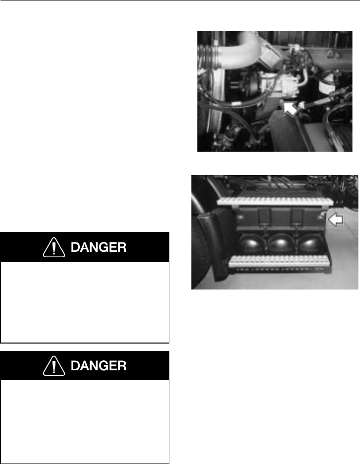
Electrical System 245
Charging System
An alternator with an integrated regulator is
used to supply power to the vehicle electri-
cal system. The charging system voltage
should be checked periodically to prevent
overcharging or undercharging the batteries
and to detect any voltage drop in the wiring.
W8002769
Battery Box
The battery cover may also be a base for
the cab steps. To remove the cover, unhook
the two rubber latches and lift the cover up
and out.
When installing the battery cover, make
sure it is resting properly on the box
before fastening the latches. Faulty in-
stallation may cause the cover to shift
when the steps are used, which may lead
to a fall, causing serious personal injury
or death.
When inspecting or cleaning batteries,
never smoke or expose batteries (or the
areas around them) to spark or flames.
The battery area may contain an explo-
sive gas mixture that can ignite, causing
an explosion, leading to serious personal
injury or death.
W3002421
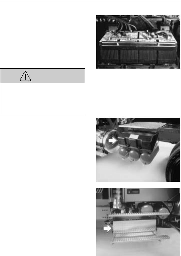
246 Electrical System
There may be three or four batteries in-
stalled. Always make sure the batteries are
fastened properly in the box.
When disconnecting battery terminals, al-
ways disconnect the main ground terminal
first. When reconnecting, always connect
the main ground terminal last.
WARNING
Battery posts, terminals and related ac-
cessories contain lead compounds,
chemicals known to the state of Califor-
nia to cause cancer and reproductive
harm. Wash hands after handling.
W3002368
There are two styles of battery boxes avail-
able. One is covered with a plastic cover
and the other cover is made of chromed di-
amond plated steel.
W3004389
W3004390
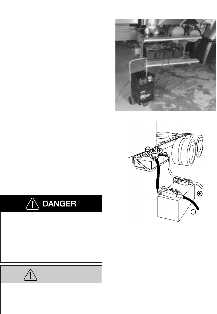
Electrical System 247
Battery Jump Starting and Charging
To access the batteries on a vehicle
equipped with side fairings, open the fair-
ing access cover. On the second battery
from the front there are special, longer
posts installed to accept jumper cables.
When jumping batteries to start an engine,
it is important that the jumper cables are
connected directly from one set of batteries
in one vehicle to the other set of batteries
in the other vehicle (unless vehicle is
equipped with optional Emergency Start
System). This way the cranking current is
carried through the proper starter wiring.
W3004391
Connect the jumper cables to the positive,
or “hot” terminal first and ground terminal
last. When disconnecting the cables, dis-
connect the ground terminal first. Connect
the jumper cable clamps to the discharged
battery first and to the booster battery last.
Avoid creating sparks by making all con-
nections quickly and firmly. Do not permit
vehicles to touch each other when jump
starting.
Do not attempt to jump-start a vehicle
equipped with Delco Maintenance Free
batteries if the test indicator is light yel-
low. Replace the battery instead.
Jump-starting may cause battery to ex-
plode causing skin burns from acid or
serious personal injury or death.
WARNING
Always wear eye protection when work-
ing around batteries to prevent the risk
of injury due to contact with sulfuric
acid or an explosion.
W3002432

248 Electrical System
Charging the Battery
High voltage machines that are used for
work on the vehicle can do damage to the
electrical system, especially to its electronic
components. Welding or quick-charging
machines subject the wiring to excessive
voltage, which may often result in damage
to electrical and electronic components
anywhere on the vehicle.
CAUTION
Attempting to work on electronic com-
ponents without proper equipment can
damage internal parts with static elec-
tricity.
Do not work on the electrical system
without the proper tools and training. Re-
pairwork to the electrical system must
always be done by trained professionals.
Your Volvo Truck dealer has the right tools
and trained technicians.
Jump Starting the Engine
If the batteries are discharged to the point
where they do not have enough stored en-
ergy to start the engine, they should be
recharged using a low charge current, not
to exceed 16 volts.
If the vehicle needs to be started immedi-
ately, use starting batteries. Connect the
batteries according to the information on
the previous page.
DO NOT use battery chargers with
“boosting” capability. These produce a high
voltage current that will cause damage to
the vehicle electrical and electronic
components.
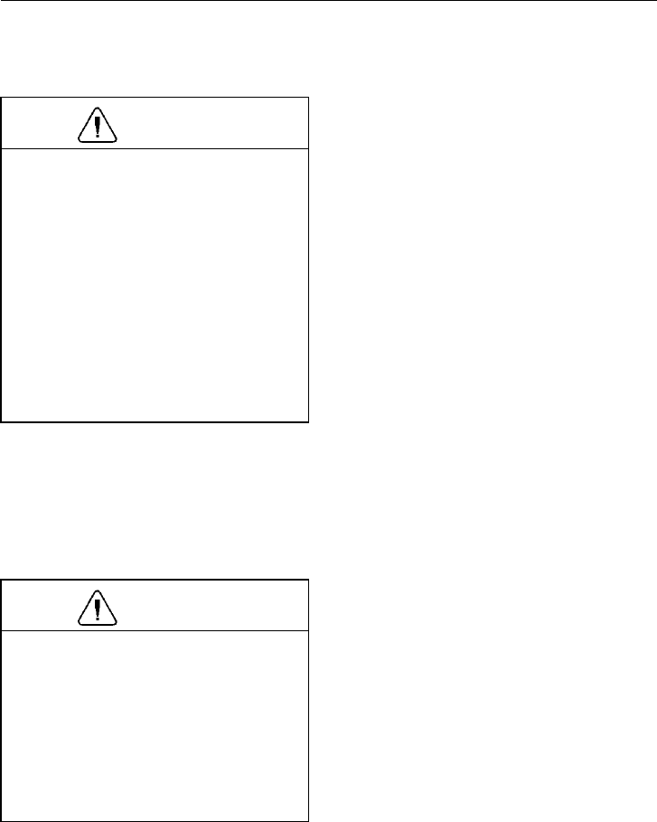
Electrical System 249
Electronic Components
CAUTION
Electronic circuits and components are
designed to sense voltage differences
smaller than 1 volt. While static electric-
ity is not normally dangerous to humans,
it can seriously damage electronic cir-
cuits and components. Circuit boards
mounted in the instrument cluster may
not fail immediately after being hit with
a static discharge. Rather, they may work
for a while and then fail for no apparent
reason. Therefore, always work with
proper grounding straps and antistatic
mats around electronic components.
Welding
CAUTION
Welding on the vehicle can damage the
electrical system or components due to
the high voltage and current spikes that
normally occur when welding. It is
preferable to avoid welding on an as-
sembled vehicle. However, if any
structure on or in contact with the
vehicle must be welded, follow the rec-
ommendations below.
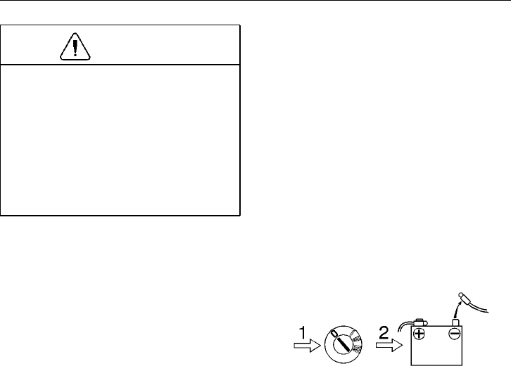
250 Electrical System
CAUTION
If there are other ground cables con-
nected to the battery (such as engine
ECU, etc.), disconnect those ground ca-
bles first, then remove the main battery
ground cable. Electronic modules may
be damaged when additional grounds are
connected/disconnected without the
main battery ground connected. Discon-
nect the main battery ground last.
Before welding on the vehicle, electrical
power needs to be disconnected and some
components must also be disconnected:
•Disconnect both the negative (-) and
positive (+) battery cables. Disconnect
the negative cable first. Reconnect the
positive cable first.
•Disconnect engine/starter ground from
the chassis. This connection is located
outside the left hand frame rail in the
engine compartment.
•Disconnect the power harness and ve-
hicle interface harness at the engine
electronic control unit (EECU).
•If the vehicle is equipped with systems
that have their own ECUs (such as the
vehicle ECU (VECU), ABS system,
air bag or some transmission systems),
disconnect each ECU at their electrical
connection.
•Disconnect the electrical connections
at the rear of the instrument cluster.
•Reposition or shield any parts that
would be damaged by high
temperatures.
T8006862
Electrical System 251
•Attach the welder ground cable as
close to the weld area as possible (6
inches or less from the place being
welded).
•Do not connect the welder ground ca-
ble to the EECU or its cooling plate.
•Welding cables should not be allowed
to lay on, near or cross over any elec-
trical wiring or electronic component
during the welding procedure.
•After finishing welding and the welded
areas having cooled, inspect wiring
and components for possible shorts or
damage. In the event of a short circuit,
excessive current will be drawn when
the batteries are reconnected, causing
more damage to the electrical system.
CAUTION
Do not weld on the engine or engine
components. Welding on the engine or
components mounted on the engine can
cause serious damage to the engine
ECU.
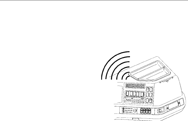
252 Electrical System
Battery Protection System (option)
An electronic battery monitor (“Battery
Lifeguard”) may be installed in the electri-
cal center. This monitor will disconnect
certain circuits if it senses that the battery
voltage falls under a safe charging level.
Before disconnecting, the monitor will
sound a loud and distinct alarm, alternating
long and short beeps, for approximately
60 seconds.
At the end of the alarm, the monitor discon-
nects circuits to protect the batteries. When
the batteries are charged, either through the
vehicle alternator or a connected battery
charger, the monitor will automatically re-
store power to the disconnected circuits.
Disconnected circuits are connected to fuse
positions F15 through 35. These circuits are
primarily feeding the sleeper area and
headlights.
Unless the batteries are held at an elevated
voltage for several hours, they will only de-
velop a “surface” charge. That charge will
quickly go away and the relay will retrip.
W3002365
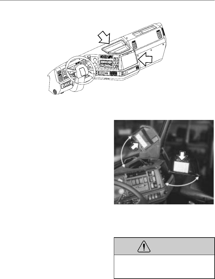
Electrical System 253
Electrical Center
W8000923
The electrical center is located in the mid-
dle of the dash. All the relays and fuses in
the cab are collected here. The cover panels
are fastened with screws that can be turned
with a coin. Since the function of some
fuses or relays may change for the vehicle
application, refer to the list of functions that
is attached to the underside of each panel.
All fuses and relays are accessible under
the top cover.
W3002514
Fuses are standard. Reset breakers are avail-
able as an option for some circuits. If a fuse
continues to melt or disconnect, the circuit
has a malfunction and must be repaired.
If a breaker disconnects, the ignition or
main switch must be switched off before
the breaker resets.
WARNING
Failure to repair a malfunction in the
electrical system can result in serious
damage due to vehicle fire.
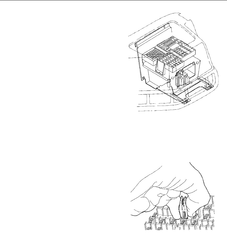
254 Electrical System
The fuses and relays are all accessible un-
der the top cover on the dash.
W3002526
One type of fuse in the new electrical cen-
ter are termed “mini-fuses” and require a
puller tool to remove from the fuse block.
The puller tool is part of the Owner’s Pack-
age. To order a new puller, use part number
20378326.
W3002525
Mini-fuse puller tool
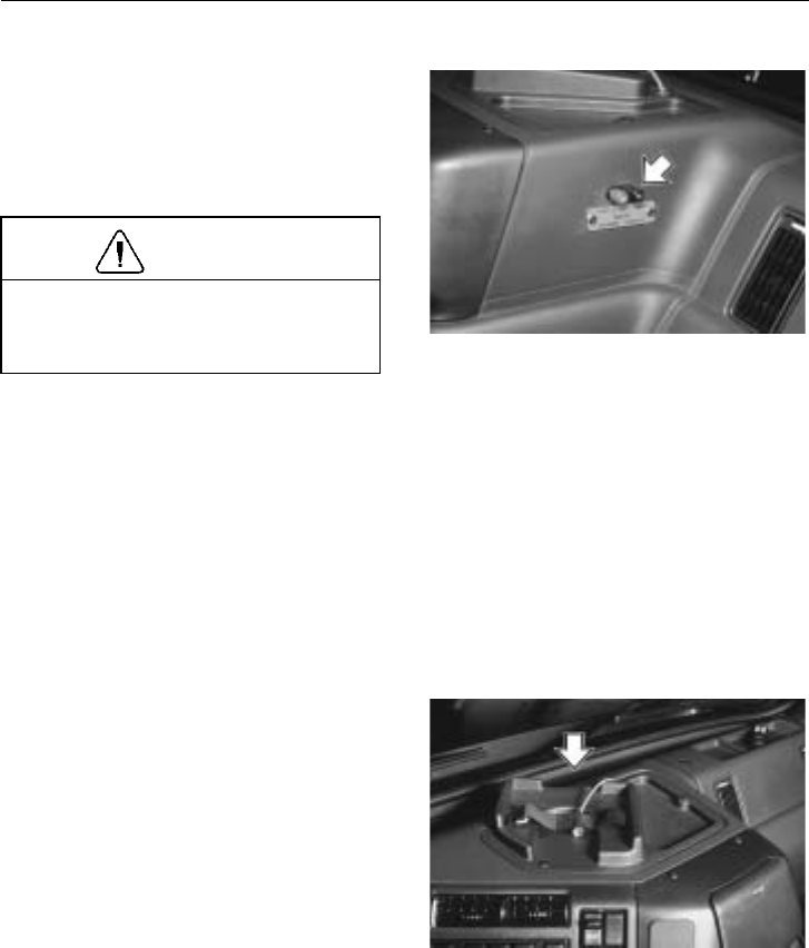
Electrical System 255
Power Studs
On the passenger side of the dash are
power studs for a CB hook-up. These studs
are standard equipment. For a proper hook-
up, use fork type connectors on the wires
or use “banana” plugs.
CAUTION
If stripped wire ends are used, make
sure there are no wire strands that can
bridge between the studs.
The red stud is the positive terminal and
the black stud is the ground terminal.
Power from the studs must not exceed a
10 amp draw. Before connecting any elec-
trical accessory, make sure it is made for
12 V operation.
W3002001
The top tray is available as a CB mount
with a strap to hold different size radios se-
curely in place.
W8001876
12 Volt Power Outlets
There are a number of 12 V outlets that
can be accessed in the cab. On the dash,
there are cigar lighter and CB power studs
as possible 12 V outlets.

256 Power Steering
General
The power steering consists of an inte-
grated gear and hydraulic power cylinder,
and a power steering pump with fluid con-
tainer. The pump, driven by the engine,
provides hydraulic pressure to the power
steering. If the engine is not working, the
steering is only manual. With the power
steering not working, the effort required to
turn the steering wheel is much greater
than with power assist. If the power steer-
ing assist fails, bring the vehicle to a safe
stop. Do not drive the vehicle until correct-
ing the cause of the problem.
Do not drive the vehicle without power
assisted steering. When the power assist
has failed, the effort to turn the steering
wheel is much greater, especially in
sharp turns or at low speeds. This can
cause an accident and lead to serious
personal injury or death.
While operating the vehicle, avoid ruts and
obstructions which cause a binding condi-
tion on the sides of the front wheels. Drive
the vehicle out of the rut, then turn the
steering wheel. If possible, avoid turning
the wheels while the vehicle is at a stand-
still as this places a considerable load on
the power steering system and front axle.
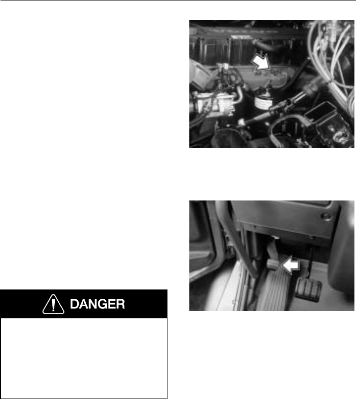
Power Steering 257
Periodically check the power steering fluid
reservoir and keep it filled to the proper
level with the recommended fluid. See the
“Operator’s Manual, Maintenance and En-
gine” for more information.
There is also a filter inside the reservoir
that needs to be changed every 12 months.
W6001428
Adjustable Steering Column (option)
The steering column is fixed as standard.
An adjustable steering column is available
as an option. The adjustment device is op-
erated by a pedal on the left side of the
floor. To make adjustments, depress the
pedal and move the steering column to the
desired position and then release the pedal.
Do not try to make adjustments to the
steering wheel while the vehicle is mov-
ing. Make all adjustments before starting
to drive. Adjusting steering column
while driving could cause loss of vehicle
control leading to severe personal injury
or death.
W6000876

258 Axles and Wheels
Axles
Differential Locks
The drive axle(s) may be equipped with
differential locks. The single drive axle will
only have a wheel differential lock. With
tandem drive axles, there could be both
wheel differential locks and an inter-axle
differential lock.
CAUTION
Never operate the vehicle with the dif-
ferentials locked any longer than is
necessary as this places a great strain on
the axles and may cause rapid tire wear.
The differential lock should be used on icy
or slippery surfaces. As soon as the
slippery surface has been passed, the differ-
ential lock should be disengaged.
Differential locks must not, under any cir-
cumstances, be engaged when in a
wheel-spin situation. Engage the locks
ahead of the slippery area. If already slip-
ping, stop the wheels, engage the locks and
then continue. If the differential locks are
engaged when the wheels are spinning, the
differential will be damaged and the rear
axle drive unit could possibly fail.
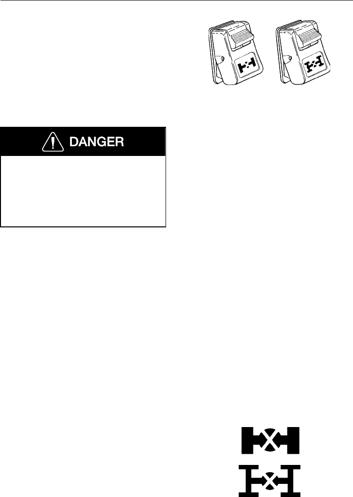
Axles and Wheels 259
Engaging the differential locks must always
be done in the following way (see page 104
for switch location):
1 Depress the clutch pedal. Wait for the
drive wheels to stop spinning
2 Engage the differential lock
3 Engage a suitable gear
4 Carefully release the clutch pedal
Do not drive on dry, paved surface with
the differential locks engaged. The vehi-
cle will strive to maintain a straight line.
Taking a curve with the differential locks
engaged may cause an accident, leading
to serious personal injury or death.
Under normal traction conditions, do not
engage the differential locks. If at all possi-
ble, do not use the differential locks while
taking a curve. With good traction and the
differential locks engaged, the vehicle will
be understeered and therefore will tend to
drive straight in a curve. When using locks
on good traction surface, drive cautiously
and do not exceed 25 mph (40 km/h). Dis-
engage the locks as soon as possible.
When the differential locks are disengaged,
the couplings may be under tension. Disen-
gage the locks by returning the switch to
the OFF position. Help with the disengage-
ment by briefly letting up on the accelerator
to relieve the torque on the couplings.
W3001991
The telltales for the differential locks are in
the instrument cluster. See page 80 for
more information on the telltales.
W3000904
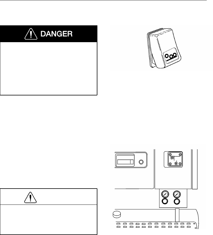
260 Axles and Wheels
Auxiliary Lift Axle
Before raising or lowering any of the
auxiliary axles, be certain no one can be
trapped by the axle movement. Failure
to do so can result in a person being
trapped between the wheel and the body,
or between the wheel and the ground,
resulting in serious personal injury or
death.
Vehicles may be equipped with auxiliary
lift axles. The lift mechanism operates with
air pressure. To lower or raise the axle(s),
press the top part of the switch in to raise
the axle and press the lower part of the
switch in to lower the axle.
W3004429
Regulators for adjusting the air spring pres-
sure are located on the outside of the cab,
below the rear corner of the driver side
door. Regulators are operated by turning the
knob counter clockwise for lowering pres-
sure, and clockwise for increasing pressure.
CAUTION
Do not rely on gauges to determine
axle pressure. Weight must be verified
on scales, and pressure in the air springs
should then be adjusted accordingly. W7001173
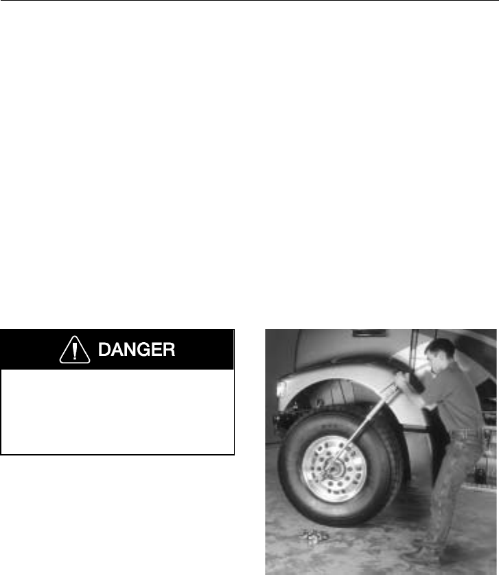
Axles and Wheels 261
Wheels
General
Due to the size, equipment needed and the
procedures used to change wheels, this
should be done through the Volvo Truck
dealer. By having an expert technician per-
form this procedure, personal injury and
property damage may be avoided.
NOTE! When replacing the wheel equip-
ment or tires, use the same size wheels or
tires as originally manufactured. Changing
the tire or wheel size will affect brake per-
formance. If changing tire size, ABS and
speedometer must be recalibrated.
Check Tightening Wheel Nuts
Failure to properly torque-tighten the
wheel nuts can result in the breakage of
wheel studs and the subsequent loss of
wheels. Loss of vehicle control and seri-
ous personal injury or death can occur.
Check tighten all wheel nuts after the first
50 to 100 miles (80 to 160 km) and the
first 50 to 100 miles (80 to 160 km) after
each tire service. This applies to both sin-
gle and dual wheels in connection with
normal service but should be performed at
least every six months.
This check tightening is particularly impor-
tant when rims or brake drums are newly
painted. Paint can flake off from these sur-
faces, causing the nuts to lose their grip
and the wheel to loosen.
See the “Operator’s Manual, Maintenance
and Engine” for correct procedures on
tightening the wheel nuts.
W7001132
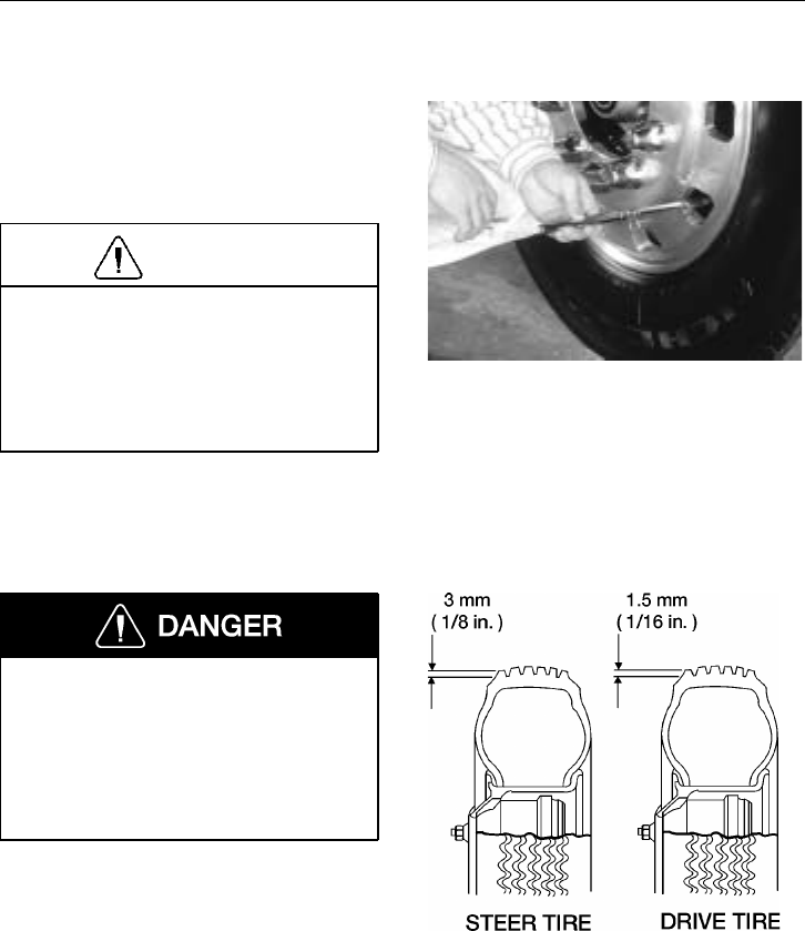
262 Axles and Wheels
Inflating Tires
Always check inflation pressures when the
tires are cool, using an accurate tire pres-
sure gauge. Check the pressures at regular
intervals.
CAUTION
Never bleed the air from hot tires. In-
creased tire pressure measured in a hot
tire is normal. Lower than recommended
pressures may cause side wall flexing re-
sulting in increased tire heat. This may
cause premature tire failure.
W7000437
Tires and wheels must be serviced only
by a qualified technician. Do not attempt
to perform this work yourself. Inflated
tires on wheels contain compressed air
and if suddenly released, do so with an
explosive force. Serious personal injury
or death can occur.
For specific information and warranty on
rims and tires, contact the tire manufac-
turer’s distributor. Check tires for abnormal
wear. Also, check the tread depth. W7000773
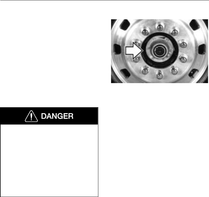
Axles and Wheels 263
Wheel Bearing Adjustment
For reliable operation and adequate service
life, the wheel bearings must be properly
adjusted and checked during the service pe-
riod. Loose wheel bearings could cause
premature tire wear and possibly affect ve-
hicle handling. See your Volvo Truck
dealer for proper servicing.
Watch carefully for oil leaks and listen for
unusual noises. These are indications of
worn bearings, bad seals or misadjusted
bearings. These are problems which must
be corrected as soon as possible.
Failure to keep wheel bearings properly
adjusted may result in accelerated tire
wear, poor handling and, in extreme
cases, wheel separation from the hub or
from the spindle.
It is important that wheel bearings are
checked and adjusted regularly. Failure
to properly maintain these bearings can
ultimately result in loss of vehicle con-
trol and cause serious personal injury or
death.
W7000438
264 Fifth Wheel Instructions
Fifth Wheel General Information
The standard fifth wheel is manufactured
by ASF. Other fifth wheels available as op-
tions are Holland and Fontaine.
Things to think about with trailer hook-up:
•Check the load distribution between
axles.
•Always chock the trailer wheels.
•Grease the plate. No grease on the
plate will produce heavy steering.
•Verify visually that coupling has oc-
curred.
•Verify visually that plungers have
locked on slider.
•Check for slack between the 5th wheel
and the trailer kingpin.
Always have all fifth wheel maintenance
and repairs done by a qualified techni-
cian. An incorrect repair can cause the
trailer to separate from the tractor caus-
ing an accident with serious personal
injury or death.
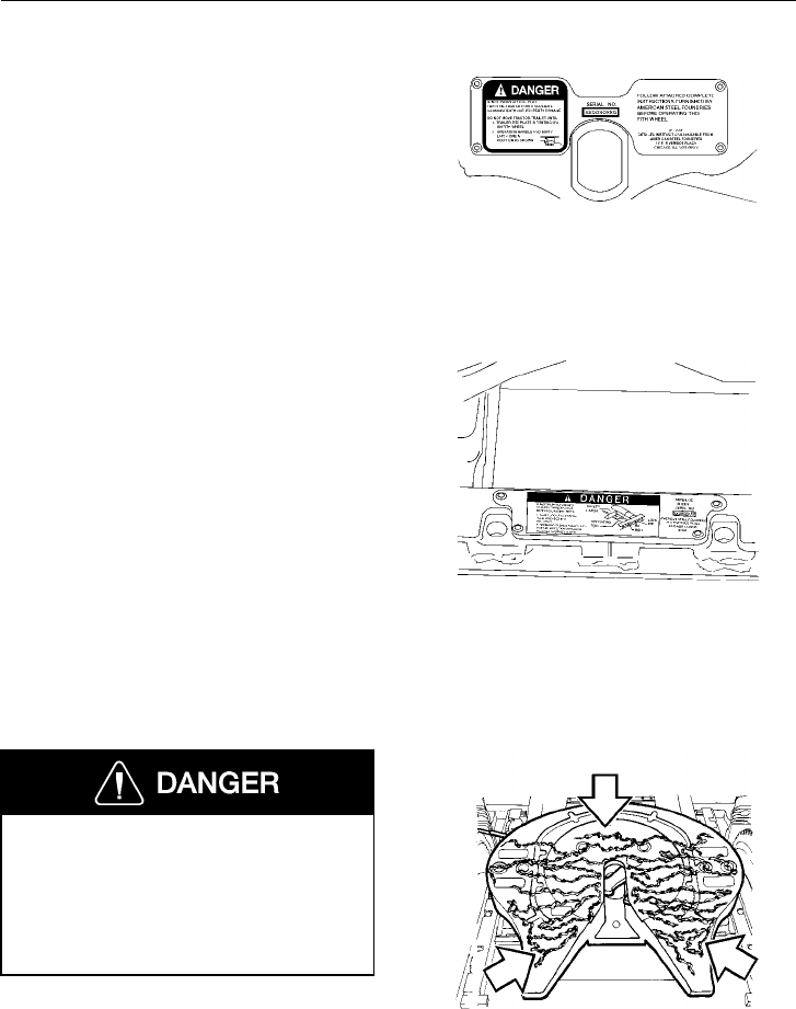
Fifth Wheel Instructions 265
Safety Information
Follow the instructions on the advisory la-
bels attached to the various manufacturers’
fifth wheels. An operator’s manual from the
manufacturer is supplied with each fifth
wheel and is provided in the Owner’s pack-
age. W9000183
If the fifth wheel is equipped with a sliding
mounting, follow the advisory labels at-
tached to the component. Also, read the
literature provided by the manufacturer.
W9000185
Always keep the fifth wheel plate well
lubricated to prevent binding between
the tractor and trailer. A binding fifth
wheel could cause erratic steering and
loss of vehicle control that may result in
serious personal injury or death.
W9000198
Fifth Wheel
There are three operating positions for the
fifth wheel locking mechanism (ASF fifth
wheel is shown):
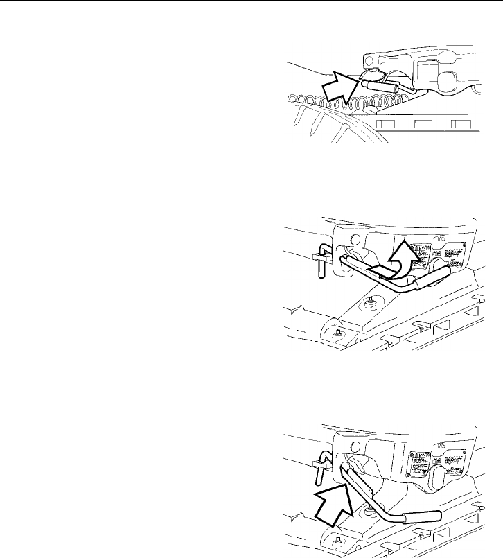
266 Fifth Wheel Instructions
Locked — This is the position that the fifth
wheel will be in with a trailer hooked up.
In the locked position, the operating rod is
retracted and the safety latch will freely
swing back and forth.
W9000180
Lockset — This is the position the fifth
wheel is in when uncoupling the trailer. To
achieve the lockset position, the operating
rod is pulled out with a slight upward mo-
tion. The operating rod shoulder will catch
on the plate casting. The safety latch is ro-
tated toward the rear of the fifth wheel.
W9000242
Open — This is the position the fifth
wheel is in after the trailer is uncoupled.
The jaw is open and the operating rod is
now dropped down and can be freely
moved around. The safety latch is rotated
toward the rear of the fifth wheel. This is
the position the fifth wheel must be in
when being coupled to a trailer.
W9000203

Fifth Wheel Instructions 267
Fifth Wheel Slider (option)
The fifth wheel comes standard with an air
operational slider. To remain within legal
weight limits, this feature allows the driver
to distribute the load easily on the axles.
The air operated slider takes the work out
of adjusting the tractor for various trailer
loads. The fifth wheel portion is easily ad-
justed, even with a fully loaded trailer
connected.
Movement between the adjustable saddle
plate and the stationary base plate rail can
result in wear, causing longitudinal, latitu-
dinal and vertical slack. Field repairs can
be made to reduce this slack for additional
service life.
W9000205
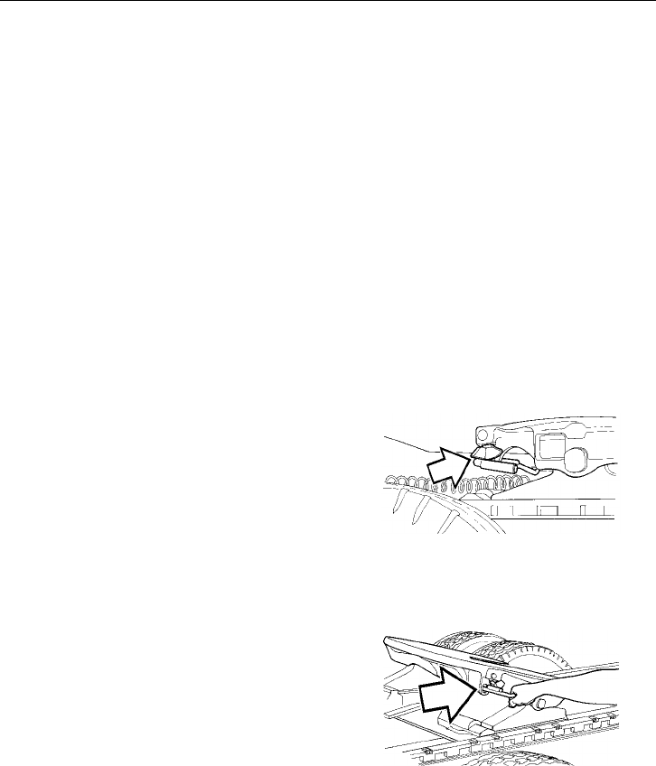
268 Fifth Wheel Instructions
Unlocking the Fifth Wheel
Always check out the entire fifth wheel
equipment before attempting to couple to a
trailer (ASF fifth wheel is shown):
•If not lubricated properly, add grease
to the top of the fifth wheel plate.
•Make sure the mounting of the fifth
wheel to the frame is tight and in good
condition.
•If using a sliding fifth wheel, make
sure the slide locking plungers are in a
locked position.
The following instructions are for preparing
the fifth wheel for coupling to a trailer:
Rotate the safety latch toward the rear of
the fifth wheel.
W9000180
Using a slight upward motion, pull the op-
erating rod out until the operating rod
shoulder is outside the fifth wheel operating
slot.
W9000202
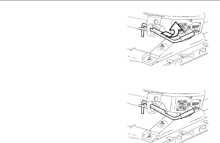
Fifth Wheel Instructions 269
When the shoulder of the operating rod is
outside of the operating slot, raise the oper-
ating rod handle to its maximum upward
position.
W9000242
Release the operating rod. The upper shoul-
der of the operating rod should now be in
contact with the plate casting above the op-
erating slot. The fifth wheel is now in the
lockset position and a trailer can be
coupled.
W9000274
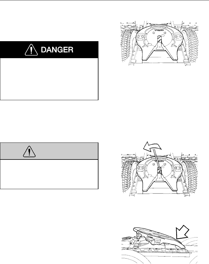
270 Fifth Wheel Instructions
Trailer Coupling Procedures
This procedure covers vehicles with and
without air suspension.
Failure to properly couple the tractor
and trailer can result in their separation,
causing death and property damage. It is
important that the operating procedures
contained in this manual are fully under-
stood and closely followed.
Using the following procedures, inspect the
equipment before coupling to a trailer:
Make sure the fifth wheel is properly lubri-
cated and the jaw is in the open position.
W8001449
WARNING
If the jaw is not in the open position,
use a pry bar to rotate the jaw to the
open position. The lock is spring loaded.
Keep hands away to avoid injury.
Use a pry bar to open the fifth wheel jaw,
if necessary. W8001450
Make sure the plate is tilted downward to
the proper position at the rear.
W9000236
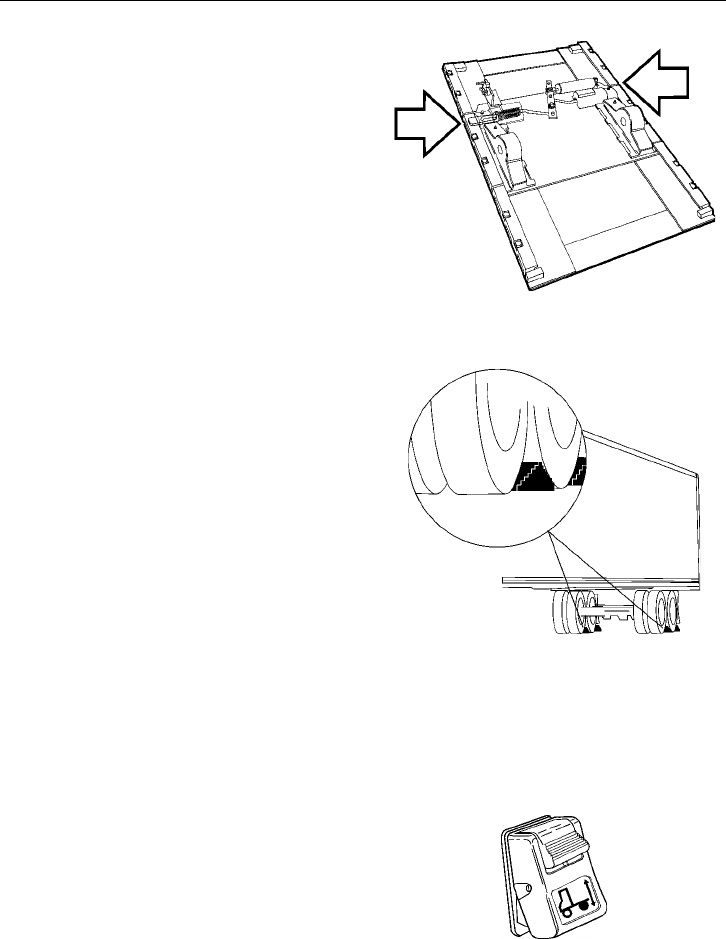
Fifth Wheel Instructions 271
Make sure the mounting of the fifth wheel
to the tractor frame is tight and in good
condition.
If using a sliding fifth wheel, make sure the
slide locking plungers are fully engaged.
W9000205
Chock the trailer wheels. Use two chocks
(both on the front and rear of the wheel) on
both sides of the trailer.
W9000263
Back up close to the trailer, centering the
kingpin on the throat of the fifth wheel, and
STOP.
NOTE! For tractors with air ride suspen-
sion, make sure the suspension control
switch is in the “RIDE” position (switch
pushed in at the top) and the air springs are
inflated.
W3001341
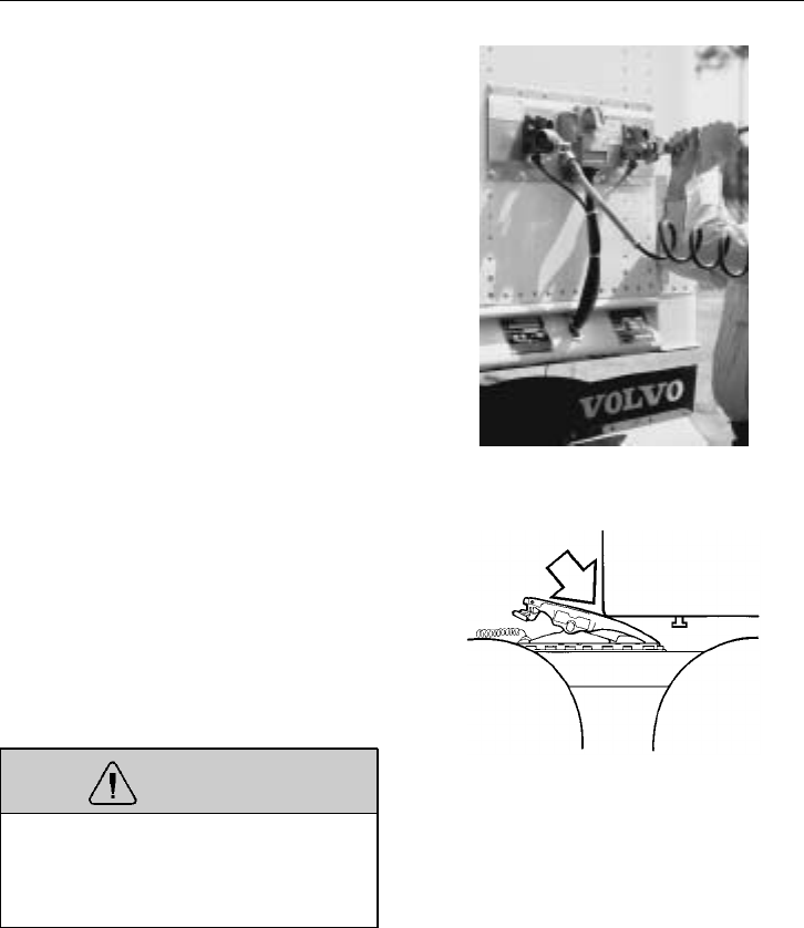
272 Fifth Wheel Instructions
Connect the air brake lines and the electri-
cal power cord. Make sure that any slack in
the lines is supported so that the brake lines
do not become entangled. Set the trailer
brakes by pulling out the Trailer Supply
control on the dashboard.
W5000713
Check to see that the trailer is at the proper
height for coupling. The leading edge of
the trailer plate should initially contact the
fifth wheel top plate surface about 8 in.
(200 mm) behind the pivot point as the
tractor backs under the trailer. Raise or
lower the trailer landing gear as required to
obtain this position.
WARNING
Attempting to couple with the trailer at
an improper height could result in a
false or improper couple and cause dam-
age to the tractor, fifth wheel and trailer.
Back under the trailer, keeping the trailer
kingpin centered in the throat of the fifth
wheel. After picking up the trailer — STOP
— then continue backing until the fifth
wheel locks firmly on the kingpin. Stopping
helps prevent hitting the kingpin too hard.
As an initial check, pull forward to test the
completeness of the coupling.
W9000237
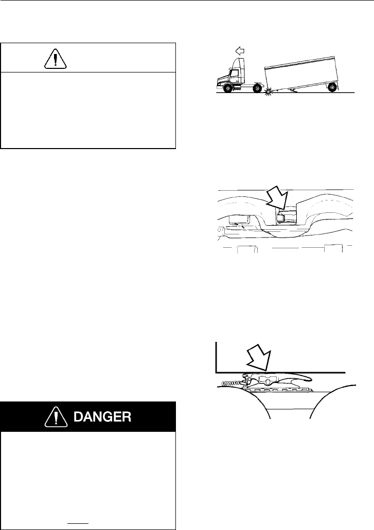
Fifth Wheel Instructions 273
CAUTION
A direct visual check is required to en-
sure proper coupling. Several types of
improper couplings will pass the initial
pull test. Sound is not reliable. Do not
take for granted that you are properly
coupled. Get out of the cab and look.
W9000286
Failed trailer coupling
Make sure the trailer kingpin is in the jaw
slot and that the jaw is closed behind the
pin. The kingpin should not overhang the
fifth wheel or be caught in the grease
groove.
To verify that the kingpin is actually in the
fifth wheel slot and the jaw is closed, the
pin must be visually inspected from the
rear. Use a flashlight if necessary.
W9000181
Make sure the trailer bed is resting on the
top surface of the fifth wheel plate, and that
there is no visible gap between the fifth
wheel and the trailer bed plate.
Proper pick-up and coupling to a trailer
is a serious matter. A trailer that be-
comes disconnected while in motion is
extremely dangerous to other traffic and
may result in death or severe personal
injury. To ensure a positive hook-up or
coupling, the procedures above should
be followed in every case.
W9000240
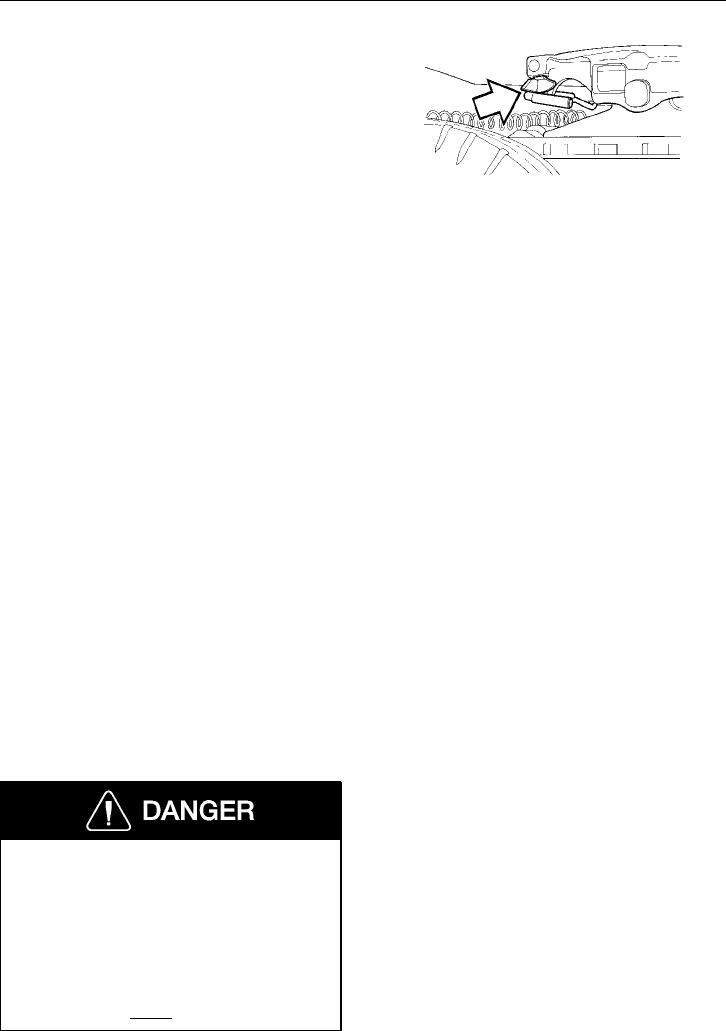
274 Fifth Wheel Instructions
Make sure the operating rod is fully re-
tracted, the safety latch is positioned above
the handle and the latch swings freely.
If the fifth wheel is equipped with a manual
secondary lock, check to see that it is prop-
erly engaged.
NOTE! If you cannot get a proper cou-
pling, repeat this procedure. Do not use any
fifth wheel which fails to operate properly.
W9000180
Check the kingpin to fifth wheel clearance
by moving the tractor backward and for-
ward with the trailer brakes set. If the
clearance appears excessive (more than
1/8 in. [3 mm]), or if the jaw does not lock,
the fifth wheel should be inspected by a
qualified technician before proceeding.
Wind up the trailer landing gear (trailer
support) to its fully retracted position. Fold
down or remove the crank handle and place
it in the crank handle holder.
Check the air brake lines and the trailer
light cord connections.
Remove the wheel chocks from the trailer
wheels.
Proper pick-up and coupling to a trailer
is a serious matter. A trailer that be-
comes disconnected while in motion is
extremely dangerous to other traffic and
may result in death or severe personal
injury. To ensure a positive hook-up or
coupling, the procedures above should
be followed in every case.
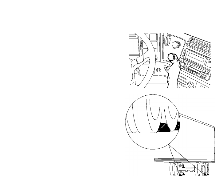
Fifth Wheel Instructions 275
Trailer Uncoupling Procedures
For Tractors With Air Ride Suspension:
Set the system park brake on the tractor.
Set the trailer brakes by pulling out the
trailer air supply knob.
W5000921
Chock the trailer wheels. Use two chocks
(one on the front and one on the rear of the
wheel) on both sides of the trailer.
W9000263
Wind down the landing gear until it touches
the ground and then give it a few extra
turns in low gear. Do not raise the trailer
off of the fifth wheel. Fold down or remove
the crank handle and place it in the crank
handle holder.
NOTE! In poor ground conditions, it may
be necessary to provide a stable base for
the landing gear.
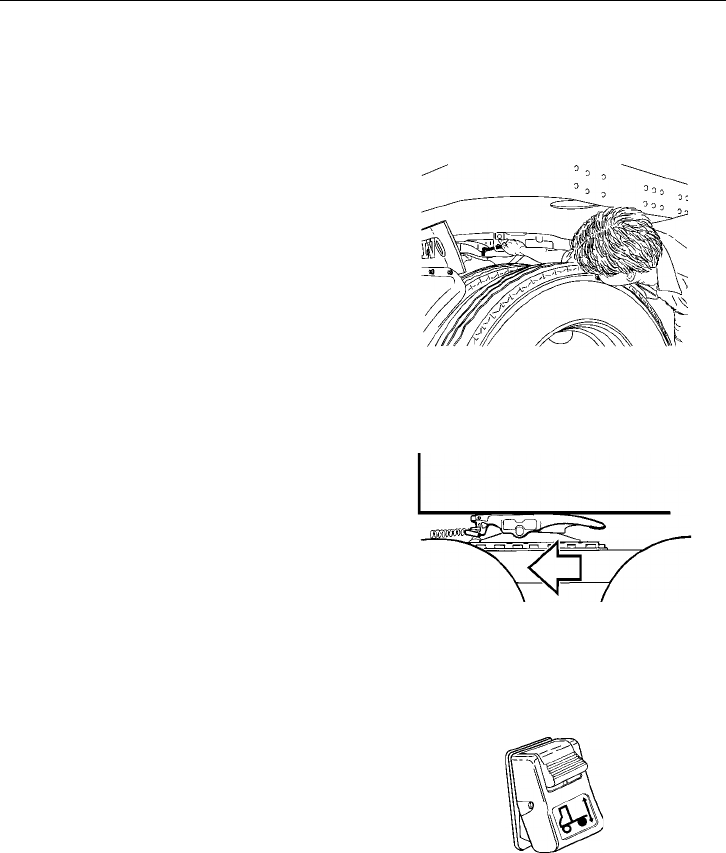
276 Fifth Wheel Instructions
Disconnect the light cord and air brake
lines. Use the dummy air couplings to keep
foreign material from entering the brake
lines.
Unlock the fifth wheel.
NOTE! If the operating rod is too difficult
to pull, back the tractor up slightly to re-
lieve any kingpin load against the fifth
wheel jaw.
W9000275
Release the tractor park brakes and pull the
tractor away from the kingpin about
12 in. (300 mm) and STOP. Do not allow
the fifth wheel to leave the underside of the
trailer.
W9000239
Select the “UNCOUPLE” position (push
down the latch and press in the bottom part
of the switch) on the suspension control
switch to deflate the air springs.
W3001341
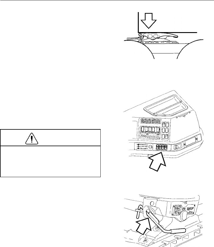
Fifth Wheel Instructions 277
Wait about 30 seconds for the air springs to
deflate.
W9000238
With the suspension lowered, pull clear of
the trailer and immediately select the
“RIDE” position (press the top part of the
switch in) on the suspension control. This
restores the suspension to operating height.
CAUTION
The vehicle must never be driven with
the air springs deflated. Damage to air
suspension parts will occur if springs are
not inflated properly.
W8001459
After the trailer is uncoupled, the fifth
wheel will be in the open position. The op-
erating rod will drop and can be moved
around freely.
W9000203
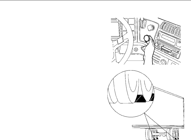
278 Fifth Wheel Instructions
For Tractors Without Air Ride Suspension:
Set the system park brake on the tractor.
Set the trailer brakes by pulling out the
trailer air supply knob.
W5000921
Chock the trailer wheels. Use two chocks
(both on the front and rear of the wheel) on
both sides of the trailer.
W9000263
Wind down the landing gear until it touches
the ground and then give it a few extra
turns in low gear. Do not raise the trailer
off of the fifth wheel. Fold down or remove
the crank handle and place it in the crank
handle holder.
NOTE! In poor ground conditions, it may
be necessary to provide a stable base for
the landing gear.
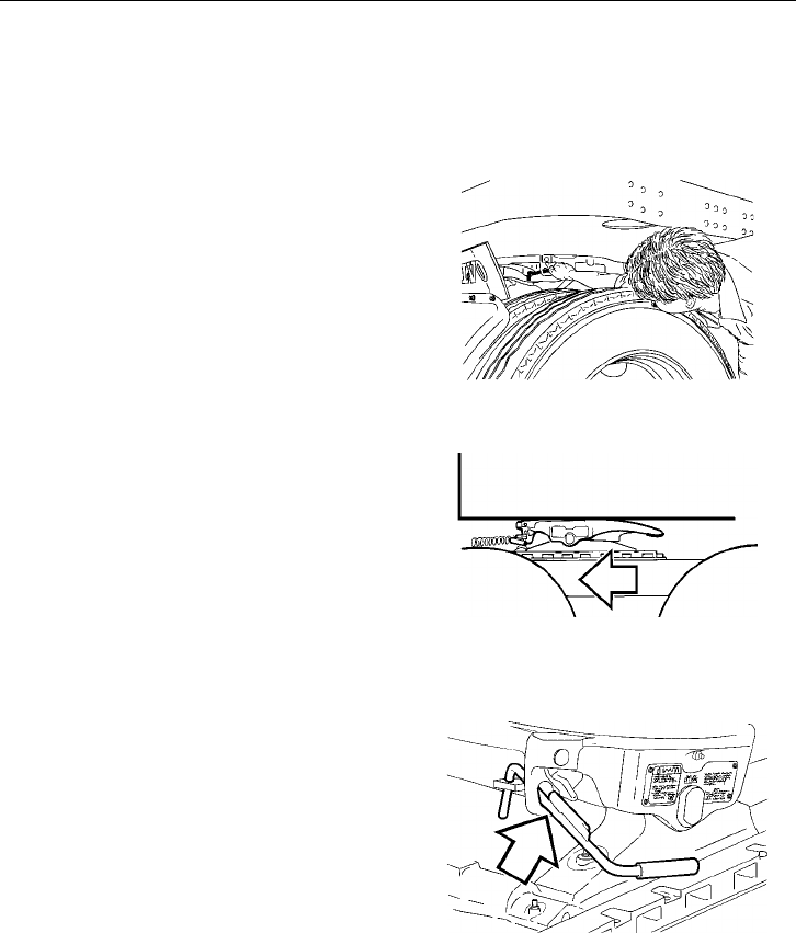
Fifth Wheel Instructions 279
Disconnect the light cord and air brake
lines. Use the dummy air couplings to keep
foreign material from entering the brake
lines.
Unlock the fifth wheel.
NOTE! If the operating rod is too difficult
to pull, back the tractor up slightly to re-
lieve any kingpin load against the fifth
wheel jaw.
W9000275
Release the tractor park brakes and slowly
drive the tractor out from under the trailer.
Let the trailer slide down the fifth wheel
and pickup ramps.
W9000239
After the trailer is uncoupled, the fifth
wheel will be in the open position. The op-
erating rod will drop and can be moved
around freely.
W9000203
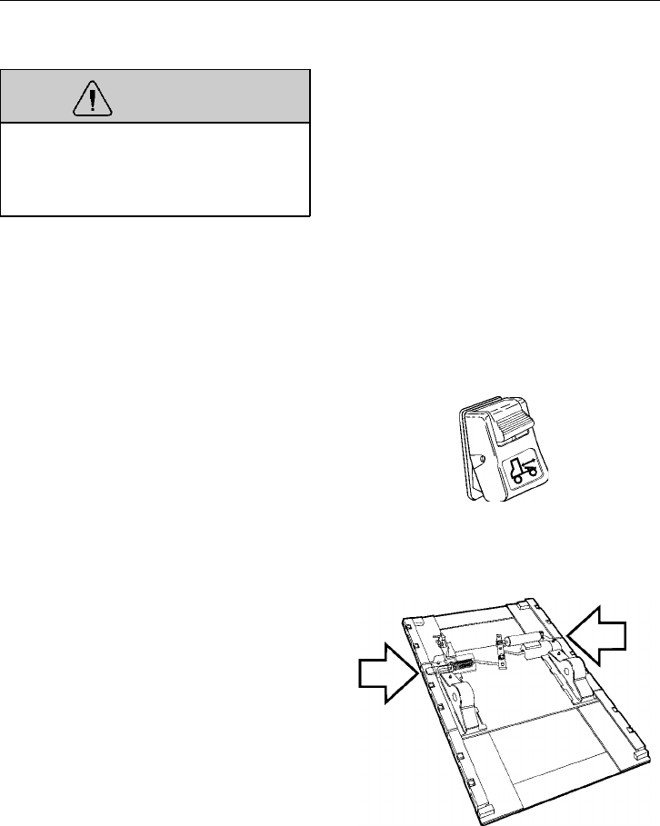
280 Fifth Wheel Instructions
Operating the Fifth Wheel Slider
WARNING
The trailer must be stopped and the
trailer brakes locked, or damage to the
tractor and/or trailer may result from un-
controlled sliding of the fifth wheel.
Stop the tractor and trailer in a straight line
on level ground.
Lock the trailer brakes by pulling out the
Trailer Supply knob.
Release the slide locking plungers by mov-
ing the switch to the “UNLOCK” position
(press down the latch and push in the bot-
tom part of the switch).
W3001346
Check to see that both of the slide plungers
have released. If the plungers do not come
out, lower the landing gear to relieve the
pressure on the plungers. Lowering the
landing gear will also allow the fifth wheel
to slide easier.
W9000205
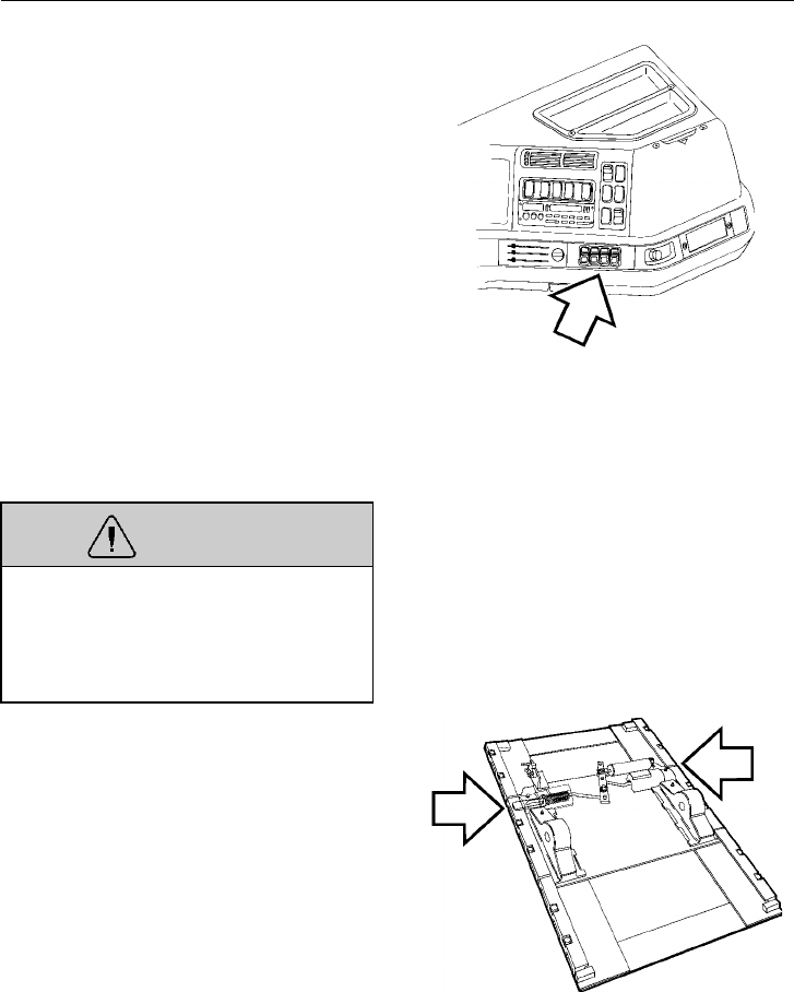
Fifth Wheel Instructions 281
Slowly drive the tractor forward or back-
ward to position the fifth wheel.
After sliding the fifth wheel to the desired
position, engage the slide locking plungers
by moving the cab switch to the “LOCK”
position (press in the top part of the switch).
W8001459
WARNING
Do not operate the vehicle if the
plungers are not fully engaged and the
trailer landing gear is not fully retracted.
Doing so may cause damage to the trac-
tor, trailer and landing gear.
Visually check to see that the slide
plungers are fully engaged. It may be nec-
essary to leave the trailer brakes locked and
to move the tractor slightly to engage the
slide plungers into the rail.
Wind up the trailer landing gear to its fully
retracted position.
W9000205
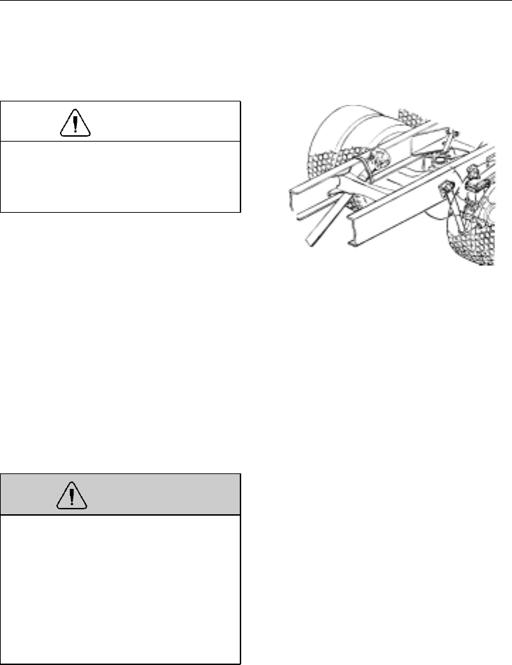
282 Emergency Information
Towing Procedure
General
CAUTION
The driveshaft must be removed before
towing the vehicle. Failure to remove the
driveshaft may result in damage to the
transmission.
Remove the drive shaft from the rear axle
before moving the vehicle, unless it only
needs to be moved a small distance for
safety reasons. When the transmission is
driven from the rear wheels without the en-
gine running, there is no lubrication in the
transmission.
Axle shafts must be removed if the vehicle
is to be towed at speeds over 25 mph
(40 km/h) or for a long distance. Openings
should be covered to prevent loss of oil and
entry of dirt and grit. Where oil-lubricated
bearings are used, openings should be thor-
oughly sealed with metal discs and new
gaskets before towing.
WARNING
If a vehicle with air suspension is lifted
by the rear frame member, there is a risk
that the air springs will separate from
the spring plates. When towing has been
completed, do not under any circum-
stances use your hands to reposition the
air springs. There is a great risk that
your hand will be caught between spring
and plate causing personal injury.
T0006670
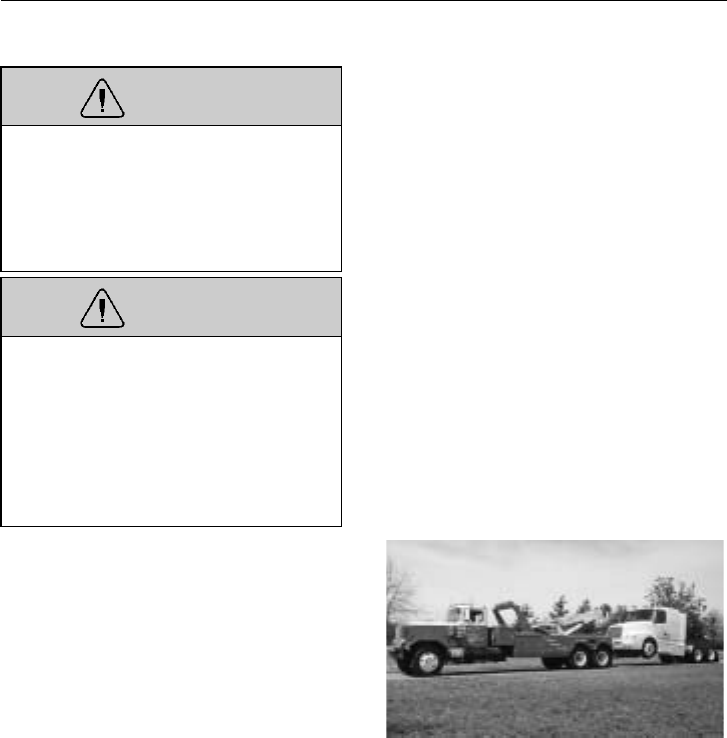
Emergency Information 283
WARNING
Do not tow a vehicle backwards when
equipped with roof air fairings. The fair-
ings act as an air scoop and may break
off. Failure to follow this warning may
lead to personal injury and vehicle dam-
age.
WARNING
Vehicles with air fairings or large super-
structures are tall. Make sure that the
total height of the vehicle, when it is
raised up behind the wrecker, does not
exceed the maximum allowed height for
local underpasses. Failure to follow this
instruction may lead to personal injury
and vehicle damage.
The vehicle may now be towed. It is rec-
ommended that a wrecker with a lift bar is
used since the service brakes will not func-
tion. The system must be filled with air to
release the parking brake or follow the me-
chanical spring brake caging procedures on
page 285.
NOTE! The power steering does not func-
tion when towing a vehicle with a disabled
engine.
W1000075
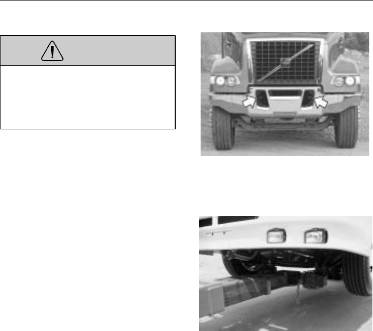
284 Emergency Information
Towing Instructions
WARNING
If the vehicle becomes disabled, it is
very important to tow it properly. Failure
to do so can cause damage to the frame
and body parts. Follow the instructions
below to avoid damage.
In the event that the vehicle cannot be
reached to place the wrecker lift bar under
the front axle, use the tow hooks in the
front of the vehicle. The front tow hooks
are used as a point at the front of the vehi-
cle where the vehicle can be pulled.
W8002767
When the vehicle is located properly, lift
the front and locate the lift bar under the
front axle and secure. Using the front axle
for towing minimizes the possibility for
damage to the vehicle body, frame and sus-
pension.
NOTE! When the drive shaft or axle shafts
are reinstalled, make sure the nuts are tight-
ened to the correct torques. Also make sure
the axle shafts are installed in the proper
sides, with the left shaft in the left side and
the right shaft in the right side.
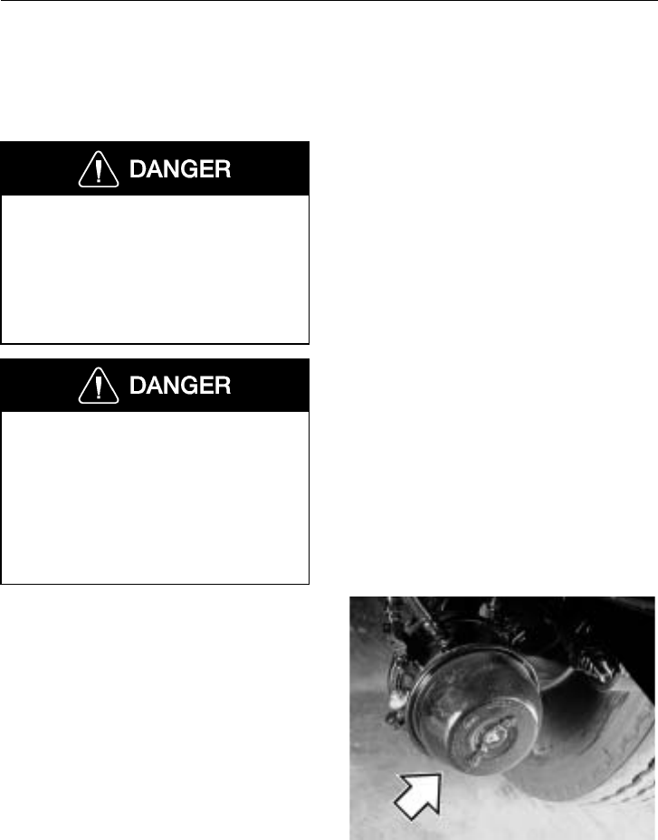
Emergency Information 285
Caging Spring Brake Chambers
The parking spring brake chambers may be
released mechanically if there is no com-
pressed air available.
Always start by chocking the wheels to
prevent the vehicle from rolling. Chock-
ing the wheels is important since you
have to work under the vehicle. Failure
to do so can result in unexpected vehicle
movement and serious personal injury or
death can occur.
In the event of brake system failure,
where the spring chambers are caged, the
vehicle cannot be driven. There would
be no means for stopping the vehicle
and this could result in serious personal
injury or death. Before caging the spring
chambers, make the connection to a tow-
ing vehicle or chock the wheels.
Remove the plastic plug in the front end of
the chamber. Remove the screw from the
holder in the side of the brake chamber. In-
sert the screw into the front hole and push
in until it bottoms. Screw into the cylinder
so at least 4 to 6 threads have entered.
W5000643
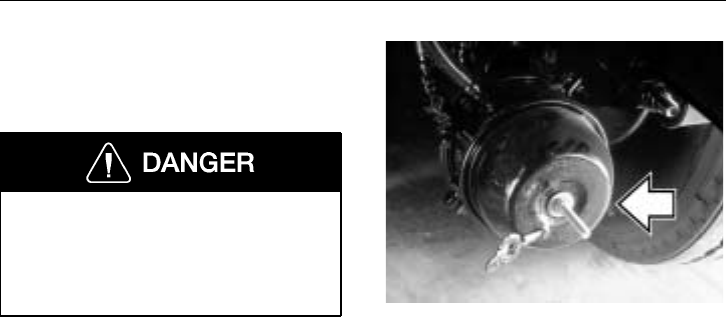
286 Emergency Information
Install the washer and nut. Tighten the nut.
This compresses the brake chamber spring
and releases the parking brake.
Do not attempt in any way to disassem-
ble or tamper with the spring brake
chamber. If the force stored on the
spring is suddenly released, it can cause
serious personal injury or death.
W5000644

Service Information 287
Service Assistance and Manuals
Your Volvo Truck dealer is trained and
equipped to perform expert service on your
Volvo vehicle. Your dealer has direct access
to Volvo Trucks North America, Inc. for
technical help, parts or service information.
There is also a direct number to Volvo Ac-
tion Service (VAS), staffed 24 hours a day,
if you are in need of assistance. The num-
ber to the Customer Support Center is:
1 (800) 528–6586 [or (800) 52–VOLVO].
Also on the internet:
www.vas.volvo.com
VAS can offer:
Delivery
Assurance If you have a breakdown,
VAS can arrange for load
forwarding or equipment
rental.
Personal
Assurance Trained staff for handling
any vehicle problems.
Uptime
Assurance VAS will locate the near-
est service provider and
guarantee payment so
you can get on the road
as soon as possible.
Price
Assurance VAS audits service and
parts billing to ensure
guaranteed labor rates
and preferred parts
pricing for Volvo compo-
nents.
There are also five regional offices that can
give information and help. They are located
in five cities around the US:
Northeast Region - Philadelphia
Ph. (610) 695-6940
Fx. (610) 993-2881
Southeast Region - Atlanta
Ph. (770) 751-3120
Fx. (770) 751-3149
Midwest Region - Chicago
Ph. (630) 734-4600
Fx. (630) 734-3086
Southwest Region - Dallas
Ph. (972) 404-3100
Fx. (972) 404-3125
West Region - Salt Lake City
Ph. (801) 352-6301
Fx. (801) 352-6350

288 Service Information
To order a single Service Manual or a Ser-
vice Manual Set for your vehicle, you
should contact your authorized Volvo Truck
dealer or fax a request to the Volvo Truck
North America, Inc. publications warehouse
[Fax: (336) 668–3625]. They will help you
locate the manual(s) you need.
To be able to handle the order correctly,
you must give the model, year and VIN
(for VIN location, see page 16).
Current prices for a Service Manual Set is
$350.00 for vehicles with a Volvo engine
and $300.00 for vehicles with a Cummins
or Detroit Diesel (engine manuals have to
be ordered separately from the manufac-
turer). If complete wiring schematics are
needed, they can be ordered for $150.00.
Billing will be done through the nearest
Volvo Truck dealer.
NOTE! Prices subject to change without
notice. Please allow 30 days for delivery.
Name Company
Address
CSZ (Province, Postal Code)
Vehicle Model Phone/Fax
Model Year VIN
Item 1:
Item 2:
Item 3:
Item 4:
Item 5:

Index 289
Index
AABS Telltale . .........82
Acknowledge Information and Stop
Messages . . ........ 124
Additional Safety Features . . . 46
Air Conditioning ....... 168
Air Filters, Cab ....... 178
Air Suspension Gauge . . . . . 84
Air Suspension Telltale . . . . . 82
Air Tanks . . ........ 234
Airbag . . . .........55
Alternator . . ........ 245
Antenna Multiplexer ..... 187
Antennas . . ........ 187
Antilock Braking System (ABS) 236
Auxiliary Lift Axle(s) ..... 260
Auxiliary Switches ...... 106
Axles and Wheels ...... 258
BBattery Jump Start ...... 247
Battery Protection System . . . 252
Blind Spots . ......... 3
Bobtail Operation ....... 4
Brake Application Gauge . . . . 84
Brake System Air Pressure Gauge 85
Brake System Controls . . . . 226
Brakes . . . ........ 223
Brakes, General ....... 224
CC-Brake . . . ........ 101
Cab Entry . . .........23
Cab Interior . ........ 184
Caging Spring Brakes ..... 285
Canadian Consumer Complaints . 6
CB-Radio . . ........ 189
Change Bulbs In Instrument . . . 89
Clutch and Transmission . . . 222
Clutch Operation ....... 222
Cold Weather Operation . . . . 205
Collision Warning System, VO-
RAD .............63
Comfort Clip . ........54
Communication and Entertainment187
Coolant Temperature Gauge . . . 69
Cruise Control . ....... 218
DDaily Maintenance Checks . . . 41
Dash Overview ........64
Daytime Running Lights . . . . 98
Diff. Lock Switch ...... 104
Diff. Lock Telltale .......80
Differential Locks ...... 258
Display Menu: Data Log Mode 146
Display Menu: Faults? .... 164
Display Menu: Fuel Economy . 157
Display Menu: Gauge ..... 153
Display Menu: Password Input . 152
Display Menu: Set-Up Mode . 126
Display Menu: System Diagnostic 131
Display Menu: Time/Distance . 159
Door Locks . . ........19
Door Operation ........20
Downhill Operation ...... 216
Drive Axle Oil Temperature Gauge 83
Driving Light Switch ......99
EElectrical Center ....... 253
Electrical Power Studs .... 255
Electrical System ....... 244
Emergency Information .... 282
Emissions Control Compliance . . 8
Engine Brake . ....... 101
Engine Break-In ....... 210
Engine Cold Start, Volvo . . . 202
Engine Idling . ....... 213
Engine Jump Start ...... 248
Engine Operation ....... 209
Engine Overspeed ...... 212

290 Index
Engine Serial Number Location,
Volvo Engine . ........18
Engine Shut-Down System . . 211
Engine Start and Operation . . 197
Engine Start Procedure .... 197
Engine Stopping ....... 200
Entering Behind Cab ......24
Entering the Cab ........23
Ether Start . . . ....... 204
Exhaust Brake . ....... 101
FFastening Safety Belt ......48
Fifth Wheel Instructions .... 264
Fifth Wheel Lock Telltale . . . . 80
Fifth Wheel Slider ...... 267
Fifth Wheel Slider Operation . 280
Fifth Wheel Unlocking .... 268
Fifth Wheel, General ..... 264
Fog light Switch ........99
Foot Brake . . ....... 226
Frame Alterations ....... 7
Fuel Economy Driving .... 190
Fuel Level Gauge .......84
Fuel Tank Caps ....... 220
Fueling ........... 221
GGauge, Air Suspension Pressure . 84
Gauge, Brake Application Pressure 84
Gauge, Brake System Air Pressure 85
Gauge, Coolant Temperature . . . 69
Gauge, Drive Axle Oil Temperature83
Gauge, Fuel Level .......84
Gauge, Oil Pressure ......70
Gauge, Pyrometer .......68
Gauge, Turbo Boost Pressure . . 71
General Information ...... 1
Graphic Display ....... 108
Graphic Display Controls . . . 109
Graphic Display Overview . . 108
Graphic Display Telltales . . . 111
HHeadlight Switch ........98
Heated Mirror Switch ..... 103
Heating and Air Conditioning . 168
Hi Beam Telltale . .......81
Hi/Lo Beam Switch ......91
High Altitude Operation .... 217
Hood Opening . . .......26
Horns ............ 107
IIdle Adjustment . ...... 214
Idle Shutdown . . ...... 215
Idling ............ 213
Ignition Switch . . ...... 201
INFO Telltale . . .......73
Info Telltale . . . ...... 113
Information and Stop Messages 112
Inspecting Safety Belts .....49
Instrument Cluster, Left Overview 68
Instrument Light Dimmer . . . 107
Instruments and Controls . . . . 64
Instruments, Overview .....64
Interior lights . . ...... 184
JJake-Brake . . . ...... 101
Jump Start .......... 247
Jump Starting Engine ..... 248
LLights, Daytime Running . . . . 98
MMain Instrument, Overview . . . 76
Marker Interrupt Switch .... 100
Master Warning Telltale .....78
Mirror Defrost Telltale .....82
NNational Standard Seat .... 181
No Charge Telltale .......75
Noise Emissions . .......13
OOdometer ...........77
Oil Pressure Gauge .......70
Overload ........... 5
Owner Information, General . . . 1
Owner’s Information Package . . 2

Index 291
PParking Brake ........ 229
Parking Brake Telltale . . . . . 81
Parking Spring Brake ..... 232
Power Outlets, 12 V ..... 255
Power Steering ........ 256
Power Steering, General . . . . 256
Power Studs . ........ 255
Pre-Trip Inspection and Daily
Maintenance . .........28
Preheater Telltale ........72
Pressure Gauge, Oil ......70
Pressure Gauge, Turbo Boost . . 71
PTO Speed Adjustment . . . . . 97
Pyrometer Gauge ........68
RRadio ............ 188
Raise Hood . .........26
Rear Axle Serial Number Loca-
tions, Volvo . .........18
Road Relay . ........ 189
Roadside Assistance ..... 287
SSafety Belt Replacement . . . . 53
Safety Belt Telltale .......81
Safety Belts . .........46
Safety Defects, Reporting . . . . 6
Safety Equipment .......62
Safety Guidelines, Electrical Sys-
tem............. 244
Safety Guidelines, Fifth Wheel . 265
Safety Information, Brakes . . 223
Seat, National ........ 181
Seat, Stationary ....... 183
Seats ............ 180
Selling Vehicle ......... 1
Service Assistance ...... 287
Service Information ...... 287
Service Manuals ....... 288
Sliding 5th Wheel Switch . . . 105
Speedometer . .........77
Spring Brake Chambers, Caging 285
SRS Airbag . . ........55
Steering Column, Adjustable . 257
Stereo ............ 188
Stop Engine Telltale ......74
Stop Telltale . . ....... 120
Suspension Level Switch . . . 105
Switches, Left Cluster .....94
Switches, Optional ...... 106
Switches, Pneumatic ..... 104
Switches, Right Cluster .... 100
TTachometer . . ........76
Tag Axle(s) . . ....... 260
TCS Switch . . ....... 100
TCS Telltale . . ........87
Telephone . . . ....... 189
Telltale Bulb, Replacing .....89
Telltale Overview .......66
Telltale, 5th Wheel Lock . . . . 80
Telltale, ABS . ........82
Telltale, Air Suspension .....82
Telltale, Auto Neutral ......88
Telltale, Check Transmission . . 86
Telltale, Diff. Lock .......80
Telltale, Hi Beam .......81
Telltale, INFO . ........73
Telltale, Master Warning . . . . 78
Telltale, Mirror Defrost .....82
Telltale, No Charge .......75
Telltale, Parking Brake .....81
Telltale, Preheater .......72
Telltale, Safety Belt ......81
Telltale, Stop Engine ......74
Telltale, TCS . ........87
Telltale, Transmission Temperature 86
Temperature Gauge, Coolant . . . 69
Tire Inflation . . ....... 262
Towing Information, General . 282
Towing Procedures ...... 284
Traction Control System (TCS) 238
Trailer Brake Hand Control . . 234
Trailer Coupling Procedures . . 270

292 Index
Trailer Supply Valve ..... 229
Trailer Uncoupling ...... 275
Transmission Retarder .... 243
Turbo Boost Pressure Gauge . . . 71
Turn Signal . . ........91
UUphill Operation ....... 216
VVehicle Access . ........19
Vendor Component Information . 1
Voltmeter . . . ....... 119
Volvo Action Service ..... 287
Volvo Standard Seat ..... 182
Volvo Trucks North America Con-
tacts ............ 287
VORAD Collision Warning System63
WWarning, temperature transmission
oil ............. 123
Welding On Frame ....... 7
Welding Precautions ...... 7
Wheel Bearings . ...... 263
Wheel Nuts . . . ...... 261
Windshield Washer Capacity . . . 43
Windshield Washers ......92
Winterfront . . . ...... 208
Wipers ............92

If you should require breakdown assistance and
need to contact facilities for towing or repair,
the VAS support center is available 24 hours per
day, 7 days per week at A Volvo1-800-528-6586.
Customer Support Specialist will answer your
questions or arrange for the assistance you need.
If you need technical assistance, the group for
technical and parts support is available 24 hours
per day, 7 days per week at 1-877-978-6586.
This assistance is available to assist you with
solving technical issues and parts issues
regarding the Volvo Heavy Duty (VHD) model
vehicle. A trained Volvo VHD Specialist for
Technical and Parts Support will give you the
assistance you need to resolve your problem.
1-800-52-VOLVO
1-877-97-VOLVO
VHD Technical and Parts Support Group
VOLVO Action Service (VAS)
Support Center

P.O. Box 26115, Greensboro, NC 27402-6115
6490 Vipond Drive, Mississauga, Ontario L5T 1W8
http://www.volvotrucks.volvo.com
Volvo Trucks North America, Inc. 2000
Volvo Trucks North America, Inc.
Volvo Trucks Canada, Inc.
PV776-TSP20 139484
Publication Date - 8/2000
