Vortech Engineering Honda Supercharger System S2000 Users Manual (4HS V1.2)S2000
2015-02-05
: Vortech-Engineering Vortech-Engineering-Honda-Supercharger-System-S2000-Users-Manual-458690 vortech-engineering-honda-supercharger-system-s2000-users-manual-458690 vortech-engineering pdf
Open the PDF directly: View PDF ![]() .
.
Page Count: 44

4HS020-010 v2.0 07/27/04
Honda S2000
Supercharger System
Installation Instructions
2000-2004 Model Years
®
ENGINEERING, LLC
1650 PACIFIC AVENUE • CHANNEL ISLANDS, CA 93033-9901 • (805) 247-0226
FAX (805) 247-0669 • www.vortechsuperchargers.com • M-F 8:00 AM - 4:30 PM PST
2000-2003 50 STATE SMOG LEGAL PER CARB EO #D-213-21
*2004 Models
*Legal in California only for racing vehicles which may never be used upon a highway.

P/N: 4HS020-010
©2004 Vortech Engineering, LLC
All Rights Reserved, Intl. Copr. Secured
27JUL04 v2.0 S2000 (4HSv2.0)
Proper installation of this supercharger kit requires general automotive
mechanic knowledge and experience. Please browse through each step of
this instruction manual
prior
to beginning the installation to determine if you
should refer the job to a professional installer/technician. Please call Vortech
Engineering for installers in your area.
FOREWORD
©
2003 VORTECH ENGINEERING, LLC
All rights reserved. No part of this publication may be reproduced, transmitted, transcribed,
or translated into another language in any form, by any means without written permission
of Vortech Engineering, LLC.
ii
NOTE:
Due to the horsepower and torque that your vehicle will
produce after installation of this supercharger system,
it is strongly suggested that the factory clutch be re-
placed with a high-capacity aftermarket unit.

P/N: 4HS020-010
©2004 Vortech Engineering, LLC
All Rights Reserved, Intl. Copr. Secured
27JUL04 v2.0 S2000 (4HSv2.0)
TABLE OF CONTENTS
FOREWORD .....................................................................................................................................ii
TABLE OF CONTENTS ....................................................................................................................iii
TOOL & SUPPLY REQUIREMENTS ................................................................................................iv
PARTS LIST - HONDA S2000 ..........................................................................................................v
1. PREPARATION/REMOVAL ..................................................................................................1
2. OIL FEED .............................................................................................................................3
3. OIL DRAIN ...........................................................................................................................4
4. CRANK DAMPER PULLEY INSTALLATION ........................................................................5
5. FUEL MANAGEMENT UNIT ................................................................................................7
6. FUEL PUMP REPLACEMENT .............................................................................................10
7. FUEL RAIL/ REGULATOR MODIFICATIONS (2004 Models Only) ......................................11
8. SUPERCHARGER MOUNTING BRACKET/PLATE INSTALLATION...................................12
9. SUPPLEMENTARY FUEL INJECTOR INSTALLATION (2004 Models Only) .......................24
10. SUPERCHARGER BELT TENSIONER ADJUSTMENT ......................................................25
11. AIR PUMP INLET HOSE MODIFICATION...........................................................................25
12. CHARGE AIR COOLER INSTALLATION .............................................................................26
13. AIR INLET DUCT INSTALLATION .......................................................................................30
14. HOSE ATTACHMENTS/EXTENSIONS ................................................................................31
15. ELECTRONIC CONTROL BOX INSTALLATION .................................................................32
16. FINAL CHECK .....................................................................................................................35
iii

P/N: 4HS020-010
©2004 Vortech Engineering, LLC
All Rights Reserved, Intl. Copr. Secured
27JUL04 v2.0 S2000 (4HSv2.0)
Before beginning this installation, please read through this entire instruction booklet and the Street
Supercharger System Owner's Manual which includes the Automotive Limited Warranties Program
and the Warranty Registration form.
Vortech supercharger systems are performance improving devices. In most cases, increases in torque of
30-35% and horsepower of 35-45% can be expected with the boost levels specified by Vortech Engineering.
This product is intended for use on healthy, well maintained engines. Installation on a worn-out or damaged
engine is not recommended and may result in failure of the engine as well as the supercharger. Vortech
Engineering is not responsible for engine damage.
Installation on new vehicles will not harm or adversely affect the break-in period so long as factory break-in
procedures are followed.
For best performance and continued durability, please take note of the following key points:
1. Use only premium grade fuel 91 octane or higher (R+M/2).
2. The engine must have stock compression ratio.
3. If the engine has been modified in any way, check with Vortech prior to using this product.
4. Always listen for any sign of detonation (pinging) and discontinue hard use (no boost) until problem is
resolved.
5. Perform an oil and filter change upon completion of this installation and prior to test driving your vehicle.
Thereafter, always use a high grade SF rated engine oil or a high quality synthetic, and change the oil
and filter every 3,000 miles or less. Never attempt to extend the oil change interval beyond 3,000
miles, regardless of oil manufacturer's claims as potential damage to the supercharger may
result.
6. Before beginning installation, replace all spark plugs that are older than 2 years or 20,000 miles with
original heat range plugs as specified by the manufacturer and retard timing from factory specifications
(follow the procedures indicated within the factory repair manual and/or as indicated on the factory
underhood emissions tag). Do not use platinum spark plugs unless they are original equipment.
Change spark plugs every at least 15,000 miles and spark plug wires at least every 50,000 miles.
TOOL & SUPPLY REQUIREMENTS:
•Factory Repair Manual
•3/8" Socket and Drive Set: SAE & Metric
•3/8” Swivel Head Ratchet
•1/2" Socket and Drive Set: SAE & Metric
•3/8" NPT Tap and Handle
•Adjustable Wrench
•Open End Wrenches: SAE & Metric
•Center Punch
•5 Quarts SH/CF Rated Quality Engine Oil
•Oil Filter and Wrench
•Flat #2 Screwdriver
•Phillips #2 Screwdriver
•Heavy Grease
•Silicone Sealer
•Drill Motor
•1/8", 3/16" Drill Bits
•Hex Key Wrench Set
•Wire Strippers and Crimpers
•Utility Knife
•Hand Held Grinder
•Blue Loctite
•07JAB-001020A (Damper Tool) Available at Honda Dealer
• 07NAB-001040A (Damper Tool) Available at Honda Dealer
•Honda Bond (Sealer) Available at Honda Dealer
If your vehicle has in excess of 10,000 miles since its last spark plug change, then you will also need:
•Spark Plug Socket
• New Spark Plugs
2000-2004
HONDA S2000
Installation Instructions
Congratulations on selecting the best performing and best backed automotive
supercharger available today... the VORTECH® Supercharger!
iv

P/N: 4HS020-010
©2004 Vortech Engineering, LLC
All Rights Reserved, Intl. Copr. Secured
27JUL04 v2.0 S2000 (4HSv2.0)
v
2000-2003 HONDA S2000
Part No. 4HS218-010SQ/-018SQ
PARTS LIST
IMPORTANT: Before beginning installation, verify that all parts are included in the kit. Report any shortages or
damaged parts immediately.
2E229-180 SUPERCHARGER ASSY 1
4HS111-021 MOUNTING BRACKET ASSY 1
4HS010-011 MTG. PLATE BLOCK 1
4HS010-021 LOWER S/C PLATE SPACER 1
4HS010-034 UPPER S/C SUPPORT PLATE 1
4HS010-044 S/C MOUNTING PLATE 1
4HS010-051 LATERAL S/C MOUNTING PLATE SUPPORT 1
7A250-075 1/4-20 x .75 SHCS 2
4PFA010-031 TENSIONER ADJ. SCREW LOCATOR 1
7PA375-500 TENSIONER SCREW 1
7B500-325 TENSIONER ARBOR 1
4HS017-051 TENSIONER SPACER 1
4HS017-011 RIBBED IDLER SPACER 1
4HS017-031 UPPER S/C PLATE SPACER 4
4HS017-021 12mm S/C BOSS SPACER 1
4HS017-041 S/C PLATE SPACER (TO STOCK IDLER) 1
7F375-028 3/8-24 PRESS NUTS 4
7B375-350 3/8-24 x 3.50 4
7C010-115 M10 X 1.25 x 115 BOLT 1
7J010-002 M10 WASHER (.080 THK.) 2
7C060-622 M6 x 1.00 x 158 STUD 2
7C010-049 M10 x 1.25 x 50 BOLT 1
7C060-080 M6 x 1.00 x 80 BOLT 3
7C012-050 M12 x 1.75 x 50 BOLT 1
7A375-124 3/8-16 x 1.25 7
7A375-350 3/8-16 x 3.50 1
7K375-040 3/8 AN WASHER 12
7J006-093 M6 WASHER 5
7F006-093 M6 NUTS 2
7J012-092 M12 WASHER 2
7F500-030 1/2-20 JAM LOCK NUT 1
2A017-016 3/8 ID BEARING PILOT (6203 BRG) 1
4GF016-160 RIBBED 3" IDLER 1
4FH016-150 SMOOTH 3" IDLER 1
4HS040-050 V-TECH SOLENOID GASKET 1
7C080-046 M8 x 1.25 x 45 SHCS 2
7A312-100 5/16-18 x 1.0 HXHD 2
7K312-001 5/16 AN WASHER 2
4HS116-011 S/C DRIVE ASSEMBLY 1
4HS016-011 CRANK PULLEY 1
7C010-050 10-24 x .50 SHCS GR8 6
4HS016-021 MODIFIED DAMPER PULLEY 1
2A046-510 S/C DRIVE BELT 1
4HS238-068 FMU assembly 1
6Z110-144 FMU ASSY 1
7U030-016 1/4 FUEL HOSE-FMU “IN” 34"
7U030-016 1/4 FUEL HOSE-FMU “OUT” 28"
7R001-004 #4 HOSE CLAMP 2
7U030-046 5/32" VACUUM HOSE 28"
7P156-082 5/32 TEE 1
7R004-003 14.5 STEPLESS CLAMP 2
4HS130-036 OIL DRAIN ASSEMBLY 1
7U030-036 OIL DRAIN HOSE 18"
7R001-008 #8 CLAMP 2
PART # DESCRIPTION QTY PART # DESCRIPTION QTY
®
ENGINEERING, LLC
7P375-004 3/8" NPTF x -8 SAE FLARE FITTING 1
7P500-050 FTG,-8 JIC TUBE x 90° W/BARB 1
7T560-001 CUTTER, 9/16" ROTABROACH 1
7T560-002 ARBOR, 9/16" ROTABROACH 1
7P375-041 3/8" NPT x 1.5" HEX NIPPLE 1
4HS130-026 OIL FEED ASSEMBLY 1
7U250-000-360 OIL FEED HOSE 1
7P125-004 #4 JIC x 90 x 1/8 NPT FTG 1
7P125-101 #4 JIC x 45 x 1/8 NPT FTG 1
7P125-125 1/8 NPT FEM x 1/8 BSPT 1
7P125-034 1/8 STREET TEE 1
7U100-055 6" ZIP-TIE 4
4HS112-010 AIR INLET ASSEMBLY 1
8H040-022 3/4" BREATHER FITTING 1
8H040-040 3.5" AIR FILTER 1
7S350-200 3.5 x 2" SLEEVE 1
7R002-056 #56 CLAMPS 2
7R002-052 #52 CLAMP 2
7U030-016 1/4" COOLANT HOSE 16"
4HS013-010 AIR BOX 1
7A250-050 1/4-20 x .5 SHCS 8
7U035-001 3.5" FLEX HOSE 5"
7U030-036 OIL DRAIN HOSE 36"
4HS110-060 AIR FILTER MOUNTING FLANGE ASSY 1
4HS012-011 3.5" PLASTIC INLET ELBOW 1
7P375-017 3/8" NPT x 1/2" BEADED HOSE BARB 1
7E010-049 #10 SHEETMETAL SCREW 2
7C060-020 M6 x 1.0 x 20 HXHD 1
4HS010-110 AIR BOX MOUNTING TAB, UPPER 1
4HS010-120 AIR BOX MOUNTING TAB, LOWER 1
8N401-010 POWERCOOLER/DISCH. ASSY 1
7A250-050 1/4-20 x .5 SHCS 2
8H040-175 RACE BYPASS FILTER 1
8N055-050 SURGE TANK CAP 1
7S275-200 2.75 SLEEVE x 2 SLEEVE 1
7S275-300 2.75 SLEEVE x 3 SLEEVE 1
7R002-044 #44 CLAMP 4
7P500-026 3/4 HOSE BARB x 1/2 NPT x 90 FTGS 2
7U030-046 5/32" VACUUM HOSE 24"
7P156-082 5/32 TEE 1
7U030-030 1/4" VACUUM HOSE 36"
7P250-033 5/32 - 1/4 REDUCER 1
008341 POWERCOOLER DECAL 1
8N301-140 WELDED COOLER CORE ASSY 1
8N106-110 WATER COOLER ASSY 1
4HS010-080 WATER RESERVOIR MNTG BRKT 1
4HS010-090 WATER COOLER MNTG BRKT, UPPER 1
4HS010-100 WATER COOLER MNTG BRKT, LOWER 2
5W001-002 FUSE TAP 1
5W001-009 SLIDE CONNECTOR - 18GA MALE 1
5W001-011 16-14 GA EYELET 2
5W001-014 FUSE HOLDER 10 GA 1
5W001-015 FUSE, BLADE TYPE 20A 1
5W001-017 12GA RING TERMINAL 1
5W001-019 12GA SOLDERLESS CONNECTOR 1

P/N: 4HS020-010
©2004 Vortech Engineering, LLC
All Rights Reserved, Intl. Copr. Secured
27JUL04 v2.0 S2000 (4HSv2.0) vi
2000-2003 HONDA S2000
Part No. 4HS218-010SQ/-018SQ
PARTS LIST,
cont’d
IMPORTANT: Before beginning installation, verify that all parts are included in the kit. Report any shortages or
damaged parts immediately.
PART # DESCRIPTION QTY
®
ENGINEERING, LLC
7A250-050 1/4-20 x .50" SHCS 2
7A250-075 1/4-20 x 3/4 SHCS PLTD 3
7E010-049 #10 x 3/4 HXHD SLF TAPNG ST MTL 9
7F250-021 1/4-20 NYLOCK NUT ZINC PLTD 3
7J250-001 1/4 SAE WASHER, PLTD 10
7P375-075 3/4" HOSE UNION 1
7P500-026 1/2NPT-3/4 BARB 90°3
7P500-078 1/2NPT x 3/4 HOSE FIT STRT 1
7R003-015 ADEL CLAMP, 15/16".406 EYELET 1
7R007-001 NYLON CLAMP 1-1/8" 10
7U038-000 3/4" HEATER HOSE 12
7U038-012 HOSE, Ø3/4" 90°, 4 x 12" 2
8F001-402 PUMP, WATER 2
8F101-310 RELAY ASSY, HONDA 1
8N006-010 WATER COOLER 1
8N055-030 TANK, LT1 AFTERCOOLER 1
5A201-001 ELECTRONICS UPGRADE ASSY
4HS010-070 BRKT, FTC MNTG S2K 2
5A001-051 TIMING CONTROL BOX 1
5A101-020 MAP CLAMP 1
5W001-009 16-14GA MALE SLIDE INSULATED 11
5W001-010 16-14GA FEMALE SLIDE INSULATED 8
5W001-022 T-TAP CONN,14-16 AWG 3
7C008-050 8-32 x 1/2 SHCS 2
7E010-049 #10 SHEET METAL SCREW 2
7F008-032 8-32 NYLOCK NUT 2
7P156-082 5/32" TEE, BRASS 1
7P157-219 REDUCER UNION, 5/32" TO 7/32" 1
7U030-046 5/32" VACCUM LINE 4'
7U100-055 TIE WRAP, 6" NYLON 8
7U375-001 VELCRO-HOOK 1" BLACK .166 YD
7U375-002 VELCRO-LATCH 1"BLACK .166 YD
8F001-342 Fuel pump assy. 1
8D204-011 Race blowoff valve 1
4HS020-010 Instruction manual 1
008110 Decals 2
008444 S/C owners packet 1
008130 Lic. plate frame, Vortech 1

P/N: 4HS020-010
©2004 Vortech Engineering, LLC
All Rights Reserved, Intl. Copr. Secured
27JUL04 v2.0 S2000 (4HSv2.0)
vii
2004 HONDA S2000
Part No. 4HS218-020/028SQ
PARTS LIST
IMPORTANT: Before beginning installation, verify that all parts are included in the kit. Report any shortages or
damaged parts immediately.
PART # DESCRIPTION QTY PART # DESCRIPTION QTY
®
ENGINEERING, LLC
2E229-210 V2SQ S/C SC-TRM CCW HONDA S2000 1
2A036-450 S/C PULLEY 4.50" 6-GRV 1
4HS111-021 MOUNTING BRACKET ASSY S2000 1
2A017-016 PILOT, 6203/5 BRG, 3/8 SCREW 1
4FH016-150 IDLR PULLEY, 6-RIB 3" FLANGED 1
4GF016-160 PULLEY, 3" IDLER-RIBBED 1
4HS010-011 MTG BLOCK, SUPPORT PLT S2000 1
4HS010-021 SUPPORT, LWR MTG PLT S2000 1
4HS010-034 S/C SUPPORT PLT, REAR S2000 1
4HS010-044 S/C MOUNTING PLT, S2000 1
4HS010-051 SUPPORT, NTG PLT, LATERAL S2000 1
4HS017-011 RIBBED LIDLER SPACER, S2000 1
4HS017-021 SPACER, S/C BOSS S2000 1
4HS017-031 SPACER, UPPER S/C PLT S2000 4
4HS017-041 SPACER, LOWER S/C PLT S2000 1
4HS017-051 SPACER, TENSNR PULLEY S2000 1
4HS040-050 GASKET, VTEC SOLENOID S2000 1
4PFA010-031 BRACKT, IDLER ADJUST SCREW 1
7A250-075 1/4-20 x 3/4 SHCS PLTD 2
7A312-100 5/16-18 x 1 HXCS GR5P 2
7A375-124 3/8-16 x 1-1/4 HXHD G5 PLATED 7
7A375-350 3/8-16 x 3-1/2 HXHD 1
7B375-350 3/8-24 x 3-1/2" HXHD GR8 4
7B500-325 ARBOR, S/C TENS PLY, S2000 1
7C010-049 M10 x 1.25 x 50 HCHD CL10.9 1
7C010-115 M10 x 1.25 x 115 HXHD CL10.9 P 1
7C012-050 M12 x 1.75 x 50mm HXHD BOLT 1
7C060-080 M6 x 1.00 x 80 SHCS CL 8.8 3
7C060-622 M6 x 1.0 x 6.22" S2000 STUD 2
7C080-046 M8 x 1.25 x 45 SHCS CL8.8 2
7F006-093 6mm NYLOCK NUT 2
7F375-028 PRESS NUT, 3/8-24 x .50 4
7F500-030 1/2-20 HEX JAM LOCK NUT ZINC 1
7J006-093 6mm WASHER, PLATED 5
7J010-002 10mm WASHER, ZINC PLATED 2
7J012-092 12mm WASHER, FLAT 2
7K312-001 5/16 AN WASHER, PLATED 2
7K372-040 3/8 AN960 FLAT WASHER, PLATED 12
7PA375-500 SCREW, IDLER ADJUST, 5.00" 1
4HS116-021 S/C DRIVE ASSY 04’ S2000 1
2A046-500 BELT, K060500-GATES 1
4HS016-011 S/C CRANK PULLEY, 6" S2000 1
4HS016-021 MODIFIED DAMPER PLY S2000 1
7C010-050 10-24 x .50 SHCS GR8 PLT 6
4HS238-048 FMU ASSY, w/LINES 4:1, S2000 1
6Z110-150 FMU, 4:1 1/4 BARB w/SPRING 1
6Z050-151 FMU WASHER, 4:1/38LB. PLATED 1
6Z070-020 FMU 4:1 RING SPACER 1
6Z090-010 SPRING, FMU GM 4.3 1
7C010-050 10-24 x .50 SHCS GR8 PLT 6
7C010-075 10-24 x 3/4 SHCS GR5 ZINC 4
7C024-025 10-24 x 1/4 PHILL HD 3
7E010-046 #8 x 3/4 SHEET METAL 2
7P125-025 1/8 NPT x 5/32 HOSE 90 1
7P125-036 1/8 NPT-STRT 1/4 BARB 1
7P125-037 1/8 NPT-90° TO 1/4 BARB 1
7U100-030 O-RING, FMU 1
7U030-016 1/4" EFI HP FUEL LINE 2
7U030-016 1/4" EFI HP FUEL LINE 2
7R001-004 #4 HOSE CLAMP 2
7U030-046 5/32" VACUUM LINE 2
7P156-082 5/32" TEE 1
7R004-003 STEPLESS CLAMP, 14.5-70 2
4HS130-026 OIL FEED ASSY S2000 1
7U250-000-360 OIL FEED HOSE, 36" -4 STRT 1
7P125-004 1/8 NPT 90° x -4 JIC FTG STL 1
7P125-101 1/8 NPT 45° x -4 JIC FTG STL 1
7P125-125 FTG, 1/8 NPT FEM x 1/8 SPT MALE 1
7P125-034 1/8 NPT x 1/8 NPT STRT T 1
7U100-055 TIE-WRAP, 7.5" NYLON 6
4HS130-036 OIL DRAIN ASSY S2000 1
7P375-004 3/8 NPT x 1/2 SAE MALE FLARE 1
7P375-041 3/8 NPT HEX NIPPLE x 1.5" 1
7P500-050 FTG, -8 JIC TUBE x 90° w/BARB 1
7R001-008 #8 STNLS HOSE CLAMP 2
7T560-001 CUTTER, 9/16" ROTABROACH 1
7T560-002 ARBOR, ROTABROACH 1
7U030-036 1/2" OIL DRAIN HOSE 1
8F001-342 FUEL PUMP w/SCREEN, GSS 342 1
5A101-021 ENGINE MNGMNT ASSY 04’ S2000 1
4HS010-070 BRKT, FTC MNTG S2000 2
5A001-121 TIMING BOX, 04’ HONDA S2000, PROG 1
5W001-009 16-14GA MALE SLIDE INSULATED 11
5W001-010 16-14GA FEMALE SLIDE INSULATED 8
5W001-022 T-TAP CONN. 14-16 AWG 3
7C008-050 #8-32 x 1/2" SHCS, ZINC 2
7E010-049 #10 x 3/4 HXHD SLF DRL SHT MTL 2
7F008-032 8-32 HEX LOCK NUT 2
7P156-082 5/32 TEE 1
7P157-219 REDUCER UNION, 5/32" TO 7/32" 1
7U030-046 5/32" VACUUM LINE 4'
7U100-055 TIE-WRAP, 7.5" NYLON 8
7U375-001 VELCRO-HOOK 1" BLACK .16YD
7U375-002 VELCRO-LATCH 1" BLACK .16YD
4HS112-010 AIR INLET ASSY S2000 1
4HS010-110 MNTG BRKT, UPR, S2000 AIRBOX 1
4HS010-120 MNTG BRKT, LWR, S2000 AIRBOX 1
4HS012-011 INLET ELBOW, 3.5" MOD. S2000 1
4HS013-010 AIRBOX, S2000 1
4HS110-060 FLANGE ASSY, AIRBOX S2000 1
7A250-050 1/4-20 x .50 SHCS ZINC PLTD 8
7C060-020 M6 x 1.0 x 20mm HHCS 1
7E010-049 #10 x HXHD SLF DRL SHT MTL 2
7P375-017 3/8 NPT x 1/2 BEADED HSE BRB 1
7R002-052 #52 SAE TYPE F SS HOSE CLAMP 2
7R002-056 #56 SAE TYPE F SS HOSE CLAMP 2
7S350-200 3-1/2 x 2 SLEEVE, BLUE 1
7U030-016 1/4" EFI HP FUEL LINE 1
7U030-036 1/2" OIL DRAIN HOSE 3
7U035-001 3-1/2" FLEX HOSE .41'
8H040-022 3/4" BREATHER 1
8H040-040 AIR FILTER, 3.5" FLG x 5.52" 1

P/N: 4HS020-010
©2004 Vortech Engineering, LLC
All Rights Reserved, Intl. Copr. Secured
27JUL04 v2.0 S2000 (4HSv2.0) viii
8N401-040 PWR COOLR ASSY, 04' HONDA S2000 1
008341 VORTECH CHARGE COOLER DECAL 1
7A250-050 1/4-20 x .50 SHCS ZINC PLTD 2
7P156-082 5/32 TEE 1
7P250-033 1/4 x 5/32 RED.UNION 1
7P500-026 1/2 NPT x 3/4 BARB 90° BRASS 2
7R002-044 #44 SAE TYPE F SS HOSE CLAMP 4
7S275-200 SLEEVE, BLUE, 2.75" D x 2.00" L 1
7S275-300 2-3/4" x 3", BLUE 1
7U030-030 1/4" VACUUM HOSE 3
7U030-046 5/32" VACUUM LINE 2
8H040-175 FILTER, 1-3/4" I.D., RACE BYP 1
8N055-050 PLASTIC CAP, SURGE TANK 1
8N301-240 PWR COOLR CORE ASSY, 04' S2000 1
8N106-110 WATER PUMP/COOLR ASY S2000 1
4HS010-080 MNTG BRKT, H20 TANK, S2000 1
4HS010-090 H20 COOLR MNTG BRKT, UPR S2000 1
4HS010-100 H20 COOLR MNTG BRKT, LWR S2000 1
5W001-002 FUSE TAP 1
5W001-009 16-14GA MALE SLIDE INSULATED 1
5W001-011 16-14GA RING TERM. .26" HOLE 2
5W001-014 FUSE HOLDER 10GA WIRE 1
5W001-015 FUSE, BLADE TYPE 20 AMP 1
5W001-017 12-10GA x 3/8" RING TERMINAL 1
5W001-019 10-12GA BUTT CONN INSULATED 1
7A250-050 1/4-20 x .50 SHCS ZINC PLTD 2
7A250-075 1/4-20 x 3/4 SHCS PLTD 3
7E010-049 #10 x 3/4 HXHD SLF DRL SHT MTL 10
7F250-021 1/4-20 NYLOCK NUT ZINC PLATED 3
7J250-001 1/4 WASHER, SAE, PLTD 10
7P375-075 3/4" HOSE BARB UNION, BRASS 1
7P500-026 1/2 NPT x 1/4 BARB 90° BRASS 3
7P500-078 1/2 NPT x 3/4 HOSE FIT STRT 1
7R003-027 ADEL CLAMP, 1-11/16" 1
7R007-001 NYLON RATCHET CLAMP 1-1/8" 10
7U038-000 3/4" HEATER HOSE 12
7U038-012 HOSE, Ø3/4" 90° 4 x 12 LEGS 2
8F001-402 PUMP, WATER, PIERBURG 1
8F101-310 FUEL PUMP RELAY ASSY, HONDA 1
8N006-010 WATER COOLR, SETRAB SINGLE PAS 1
8N055-030 TANK, WATER, TRIANGLE SHAPE 1
8D204-011 RACE BLOWOFF VALVE-SATIN 1
7A250-074 1/4-20 x .75 HHCS PLTD 2
7A312-126 5/16-18 x 1.25 SET SCRW OVAL P 1
7F312-022 5/16-18 JAM NUT, STAINLESS 1
7J006-093 6mm WASHER, PLATED 2
7P125-109 FTG, 1/8 NPT - 1/4 BARB, AL 1
7U100-086 SNAP RING, COMPACT BYPASS 1
8D003-080 RATAINER, SPRING 1
8D004-023 COVER, RACE BYPASS-BLUE 1
8D004-053 GASKET, MTG FLNG, M.F. RACE BYPASS 1
8D004-083 SPRING, MFRB, 12" HG 1
8D104-042 MFRB BODY ASSY SATIN 1
7C011-200 10-32 SHCS x 2" ZINC PLATE 1
7F010-030 10-32 THIN NYLOCK NUT SST 1
7P125-020 BREATHER, SFMU 1
7U100-049 O-RING, COMP.BYPASS 1
8D004-031 VALVE, COMPACT BYPASS ANODIZED 1
8D004-061 PISTON, COMPACT BYPASS MACHINED 1
8D004-091 DIAPHRAM, COMPACT BYPASS 1
2004 HONDA S2000
Part No. 4HS218-020SQ
PARTS LIST,
cont’d
PART # DESCRIPTION QTY PART # DESCRIPTION QTY
®
ENGINEERING, LLC
IMPORTANT: Before beginning installation, verify that all parts are included in the kit. Report any shortages or
damaged parts immediately.
8D004-141 SLEEVE, COMPACT BYPASS MACHINED 1
8D104-042R MINI BYPASS GUIDE ASSY 1
4HS020-010 INSTRUCT MANUAL, HONDA S2000 1
P/N: 4HS020-010
©2004 Vortech Engineering, LLC
All Rights Reserved, Intl. Copr. Secured
27JUL04 v2.0 S2000 (4HSv2.0)
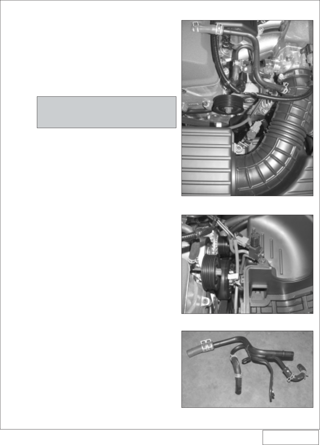
A. Disconnect the negative battery cable.
B. Remove the factory engine air filter enclosure
cover.
C. Disconnect the crankcase ventilation tube and
the air pump inlet hose attached to the rubber
inlet duct leading to the throttle body.
D. Remove the vacuum/coolant tubing junction from
the vehicle. Tag and label the vacuum hoses for
ease of reassembly in later steps. (See
Figs
1-a,1-b,1-c.
)
E. Detach the pressure solenoid from the plastic air
filter enclosure (single phillips head screw). (See
Fig. 1-b.
)
F. Separate the rubber vacuum hoses and wiring
from the air filter enclosure.
G. Remove the rubber inlet duct from the throttle
body and the air filter.
H. Remove the air filter and enclosure from the
vehicle.
I. Remove the screw securing the plastic vacuum
canister to the backside of the front crossmember
(located in front of the engine). Set aside for
reinstallation at a later time.
J. Remove the accessory belt and crank damper
pulley from the engine. Removal of the crank
damper pulley bolt may require Honda sourced
tools (07JAB-001020A handle and 07JAA-
001020A damper socket). Set aside the damper
screw for reinstallation at a later time.
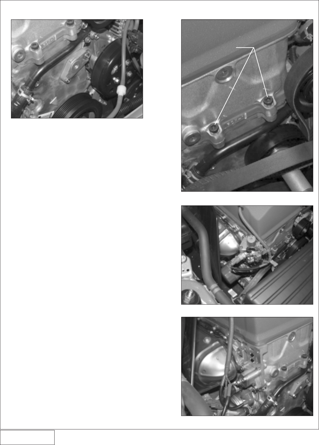
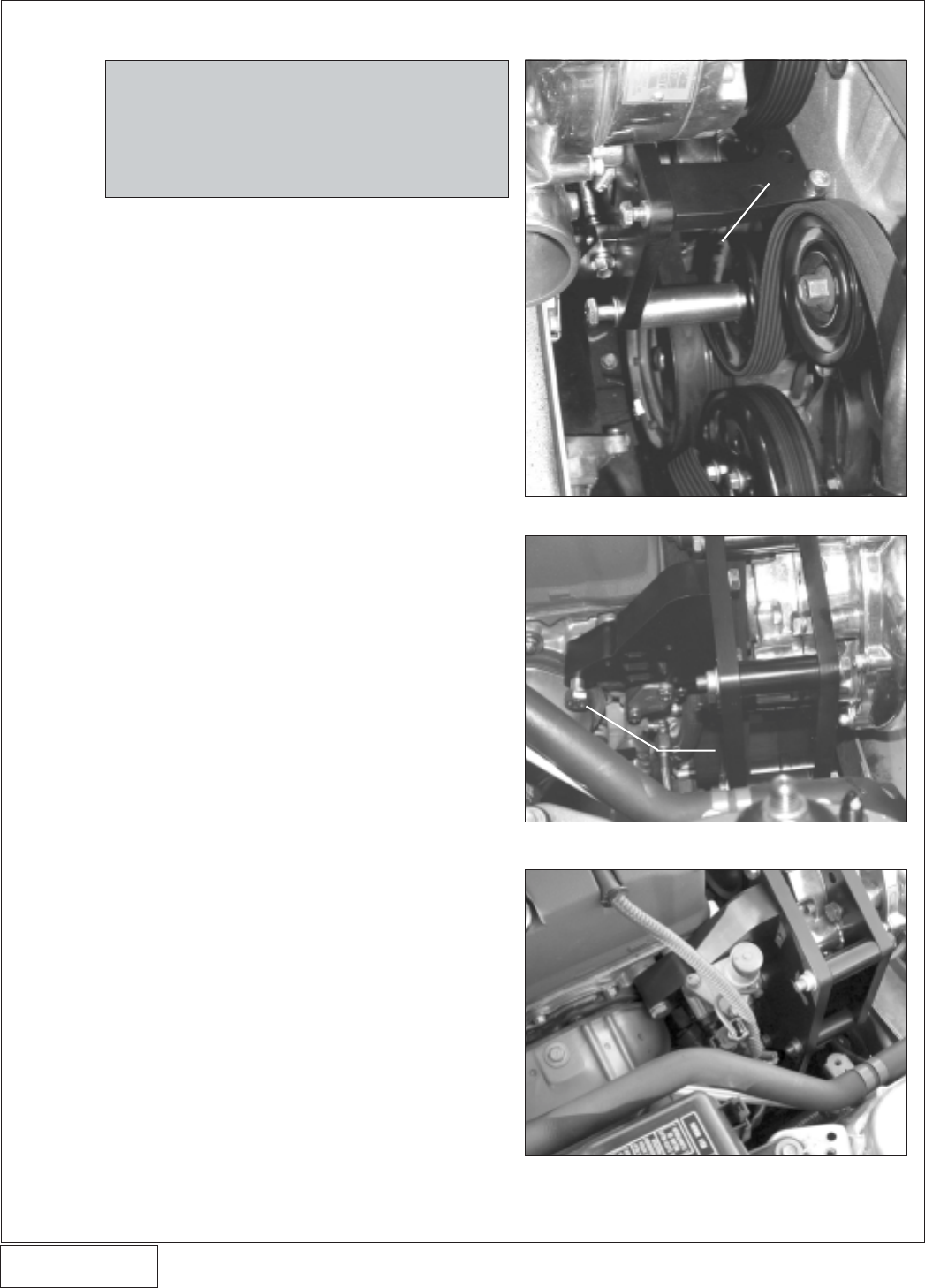
K. Remove the factory idler (smooth) pulley and
hardware and set aside temporarily. (See
Fig.
1-d.
)
L. Remove the two factory M8 x 1.25 screws that
attach the front corner of the cylinder head to the
engine front cover (see
Fig. 1-e
).
M. Disconnect the wiring from the VTEC solenoid
assembly. Remove the three screws attaching
the solenoid assembly to the side of the cylinder
head. (See
Figs. 1-f,1-g.
) Set the VTEC solenoid
assembly aside for mounting in a later step.
Make sure that the o-ring sealing gasket does not
get lost or damaged, because it will be re-used in
a later step.
1. PREPARATION/REMOVAL
Fig. 1-c
Fig. 1-b
Fig. 1-a
NOTE: Make sure that the rubber hoses that are
shown in Fig. 1-c are also removed from
the vehicle along with the tubing junction.
1
P/N: 4HS020-010
©2004 Vortech Engineering, LLC
All Rights Reserved, Intl. Copr. Secured
27JUL04 v2.0 S2000 (4HSv2.0)
2
1. PREPARATION/REMOVAL, cont’d.
Fig. 1-d
Fig. 1-e
Fig. 1-f
Fig. 1-g
REMOVE SCREWS
P/N: 4HS020-010
©2004 Vortech Engineering, LLC
All Rights Reserved, Intl. Copr. Secured
27JUL04 v2.0 S2000 (4HSv2.0)
3
2. OIL FEED
Fig. 2-a
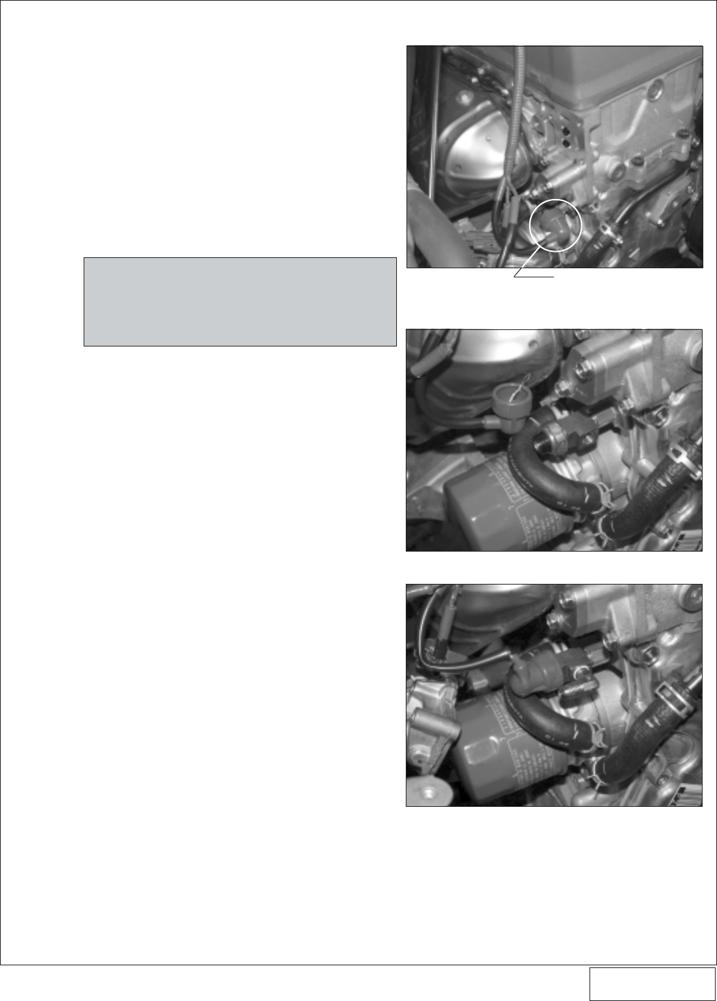
A. The supercharger uses engine oil for lubrication
and must have an oil feed line connected to a
filtered oil access on the engine.
B. Locate the oil pressure sending unit on the pas-
senger side of the engine, toward the front (see
Fig. 2-a
). Using a 7mm socket, remove the signal
wire from the sending unit. Using a 15/16 socket,
remove the sending unit from the engine.
C. Install the supplied 1/8" BSP adapter into the
block. Install the supplied 1/8" NPT street TEE
into the BSP adapter. Thread the stock sending
unit into the tee as shown in
Fig. 2-b
. Reattach
the stock signal wire and nut to the sending unit.
D. Install the supplied 90° x 1/8" NPT x #4 flare fitting
into the previously installed TEE. (See
Fig. 2-c.
)
Make sure that the fitting is tightened and clocked
as shown.
E. Temporarily cover the open fitting hole to keep
out debris until the connection is made to the
supercharger hose in step 12.
NOTE: Use only clean engine oil on the pipe
threads. Teflon tape or pipe sealant is not
recommended as it might loosen and cause
blockage of the small oil feed orifice result-
ing in possible supercharger failure.
Fig. 2-b
Fig. 2-c
OIL PRESSURE SENDING UNIT
P/N: 4HS020-010
©2004 Vortech Engineering, LLC
All Rights Reserved, Intl. Copr. Secured
27JUL04 v2.0 S2000 (4HSv2.0)
4
3. OIL DRAIN
Fig. 3-a
A. Drain the engine oil and change the filter.
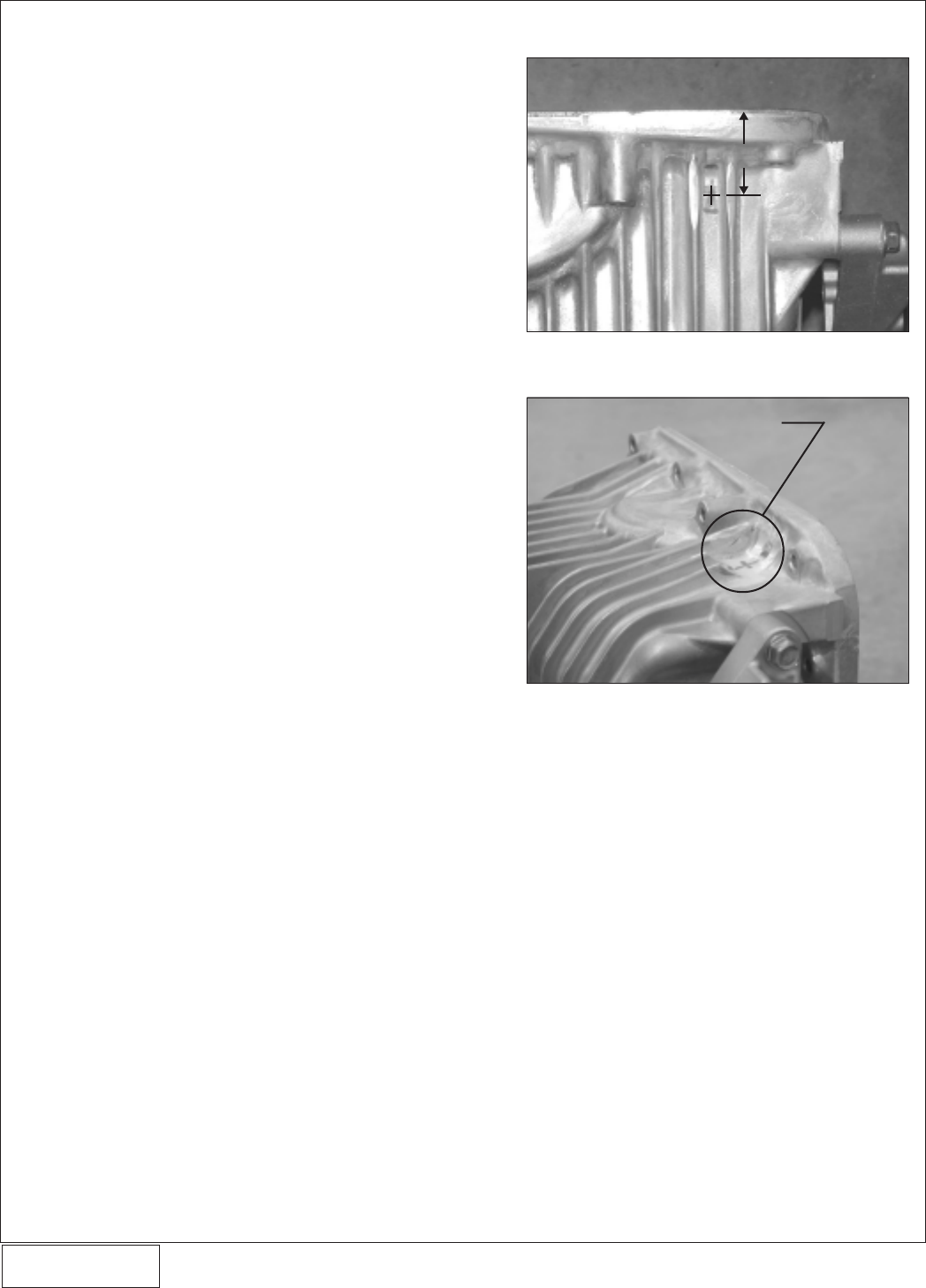
B. To provide an oil drain for the supercharger, it is
necessary to make a hole in the pan.
C. Remove (6 screws) the tubular chassis
crossmember located beneath the rear of the
engine.
D. Remove the oil pan bumper that is attached to
the vehicle frame in front of the oil pan.
E. Remove the two screws that attach the oil pan to
the transmission bellhousing.
F. Remove the two lower A/C compressor pump
mounting bolts that attach to the oil pan mounting
bracket. Leave the small aluminum mounting
bracket attached to the pan.
G. Remove the remaining oil pan screws around the
perimeter of the pan and carefully remove the
pan.
H. Locate and mark the drain hole location on the oil
pan as per
Figs. 3-a, 3-b
. The hole location is
between the two fins as shown, and down from
the sealing surface of the pan 1.25". Grind down
the fins on the oil pan as shown.
I. Using the supplied 9/16" rota-broach cutter and
arbor, carefully machine a through hole into the
pan in the location specified.
J. From the outside of the pan, tap the hole with a
3/8" NPT tap approximately 1/4" deep. Pack the
flutes of the tap with heavy grease to hold the
chips. Thoroughly clean the threads and hole
with acetone or lacquer thinner.
K. Using a small amount of silicone sealer, install
the 3/8 NPT x 1.5" hex nipple into the oil pan.
Thread the supplied 3/8" NPT female x -8 flare
fitting onto the hex nipple. Temporarily cap the
fitting until the drain hose is connected in step 12.
L. Thoroughly clean the mating surface of the oil
pan flange and the bottom of the engine block.
The surfaces must be free from oil so that a
proper seal can be achieved when the pan is
reinstalled.
M. Apply a small amount of Hondabond sealer (avail-
able at the local Honda dealership) to the oil pan
mating flange.
N. Reattach the pan to the engine. Reinstall all of
the factory hardware.
O. Reinstall the two A/C compressor screws, fac-
tory oil pan bumper and chassis crossmember.
P. Re-fill engine with factory specified weight oil.
Vortech recommends the use of synthetic oil.
Fig. 3-b
1.25”
GRIND FINS AS SHOWN

P/N: 4HS020-010
©2004 Vortech Engineering, LLC
All Rights Reserved, Intl. Copr. Secured
27JUL04 v2.0 S2000 (4HSv2.0)
5
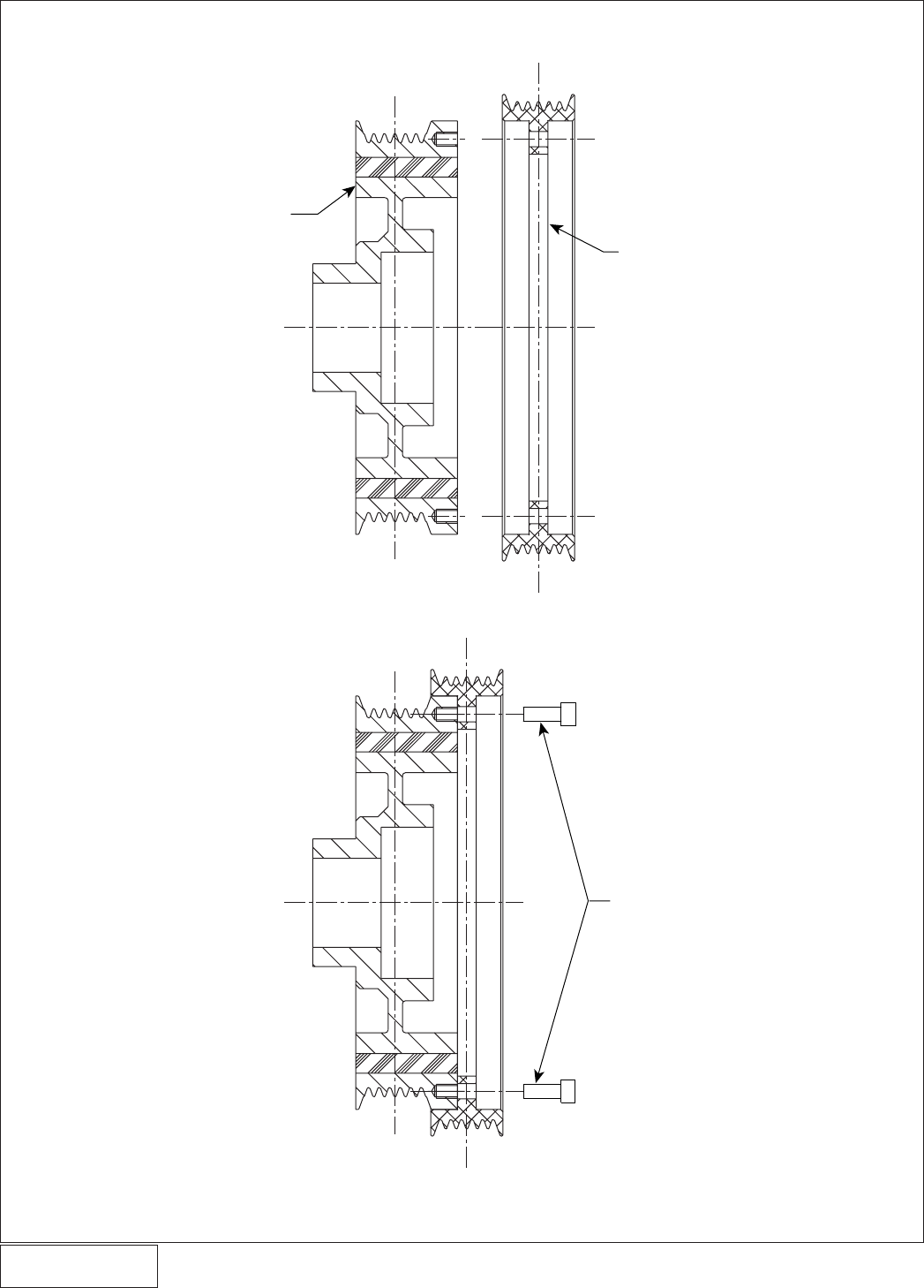
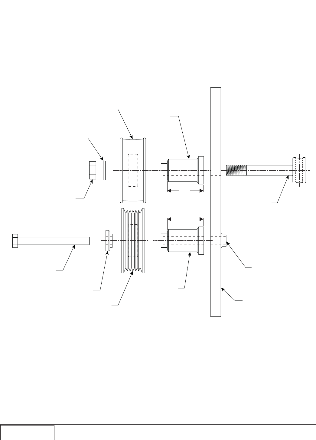
4. CRANK DAMPER PULLEY INSTALLATION
A. Locate the supplied damper pulley and billet
aluminum supercharger crank pulley.
B. The aluminum supercharger crank pulley is to be
installed over the new damper pulley as shown in
Fig. 4-a
. Be sure to rotate the aluminum pulley so
that the holes properly line up with the corre-
sponding threaded holes in the damper. Ensure
that the damper is smooth and clean where the
aluminum pulley is to be seated.
C. Carefully lower the aluminum pulley down onto
the damper. Make sure that the aluminum pulley
is completely seated onto the damper. Do not
hammer or pry the pulley into place. If neces-
sary, the aluminum pulley may be lightly heated
to allow for an easier fit onto the damper pulley
D. Secure the pulley and damper together using the
six supplied 10-24 x .50 socket head screws.
Use a drop of blue Loctite on the threads on each
of the screws. Torque the screws to 50 in/lbs (4-5
ft/lbs.)
E. Clean the damper pulley screw and washer that
were removed in step 1. Using a small amount of
engine oil, lubricate the screw threads and the
bottom side of the screw head (area that mates
to the washer). Install the new crank pulley
assembly onto the engine. Torque the screw to
181 lb/ft. Do not use an impact wrench. In order
to achieve the correct torque on the screw,
Honda sourced tools may be required (07JAB-
001020A handle and 07JAA-001020A damper
socket) to keep the assembly from rotating.
P/N: 4HS020-010
©2004 Vortech Engineering, LLC
All Rights Reserved, Intl. Copr. Secured
27JUL04 v2.0 S2000 (4HSv2.0)
6
Fig. 4-a
4. CRANK DAMPER PULLEY INSTALLATION, cont’d.
VORTECH SUPPLIED
CRANK DAMPER
PULLEY 6.0” ALUMINUM
SUPERCHARGER CRANK
PULLEY
6 x 10-24 x .50
SCREWS (TORQUE
EVENLY TO 50 IN/LBS)
P/N: 4HS020-010
©2004 Vortech Engineering, LLC
All Rights Reserved, Intl. Copr. Secured
27JUL04 v2.0 S2000 (4HSv2.0)
7
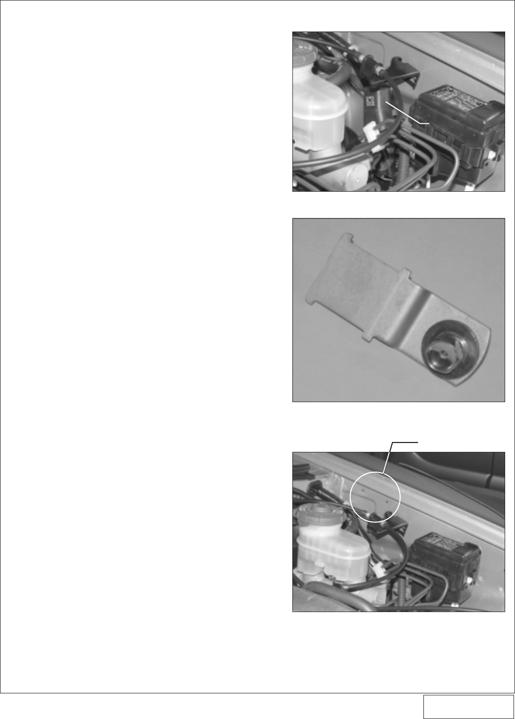
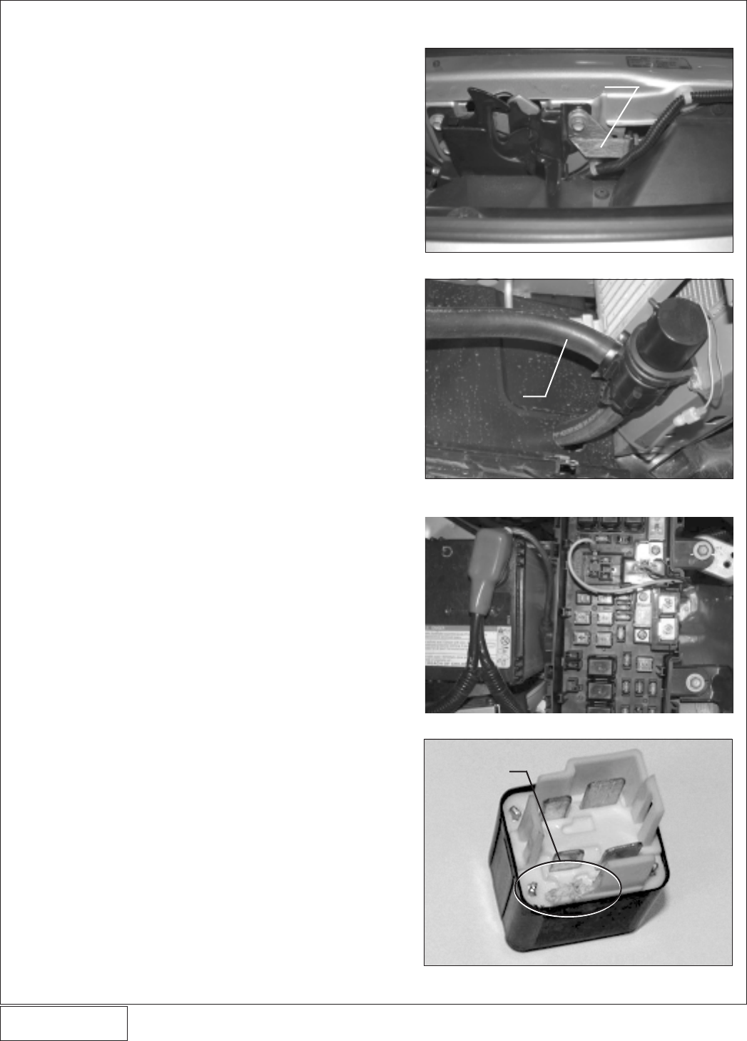
Fig. 5-a
5. FUEL MANAGEMENT UNIT
A. Disconnect and discard the factory rubber fuel
return line running from the fuel pressure regula-
tor outlet to the steel return line located under the
vehicle.
B. Remove the relay from the factory bracket/tab
near underhood fuse box. (See
Figs 5-a, 5-b
.)
Remove the bracket/tab from the vehicle and
discard. Move the relay toward the underhood
fuse box to make space for mounting of the
Vortech FMU.
C. Position the FMU onto the driver side inner
fender as shown in
Figs. 5-c, 5-d
. Mark and drill
holes and secure the FMU with the supplied
sheet metal screws.
D. Route the supplied 34” hose as shown in
Fig. 5-f
.
Connect the FMU inlet hose (the hose that goes
to the 90° fitting on the side of the FMU) to the
return side of the factory fuel regulator. Trim
hose length if needed. Secure the fuel line away
from abrasion and exhaust with the tie wraps
provided. Make sure the hose end is securely
clamped onto the regulator outlet using one of
the supplied #4 clamps.
E. Route the supplied 28” hose as shown in the
diagram. Connect the FMU outlet hose (attaches
to the center fitting on the bottom of the unit) to
the steel return line running to the tank (see
Fig.
5-e
). Trim hose length if needed. Secure the fuel
lines away from abrasion and exhaust with the tie
wraps provided. Make sure the hose end is
securely clamped onto the return line using one
of the supplied #4 clamps.
F. Attach the supplied 28” length of 5/32” vacuum
hose to the fitting on top of the FMU. Splice the
opposite end of the hose into the factory fuel
regulator vacuum connection using the 5/32”
TEE provided. Trim hose length as necessary.
Fig. 5-b
Fig. 5-c
FMU MOUNTING HOLES
RELOCATED RELAY
P/N: 4HS020-010
©2004 Vortech Engineering, LLC
All Rights Reserved, Intl. Copr. Secured
27JUL04 v2.0 S2000 (4HSv2.0)
8
5. FUEL MANAGEMENT UNIT, cont’d.
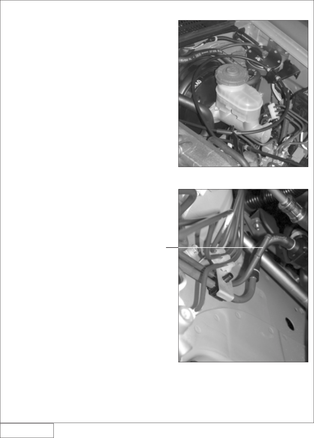
Fig. 5-d
Fig. 5-e
FACTORY RETURN
LINE INTO TANK
P/N: 4HS020-010
©2004 Vortech Engineering, LLC
All Rights Reserved, Intl. Copr. Secured
27JUL04 v2.0 S2000 (4HSv2.0)
9
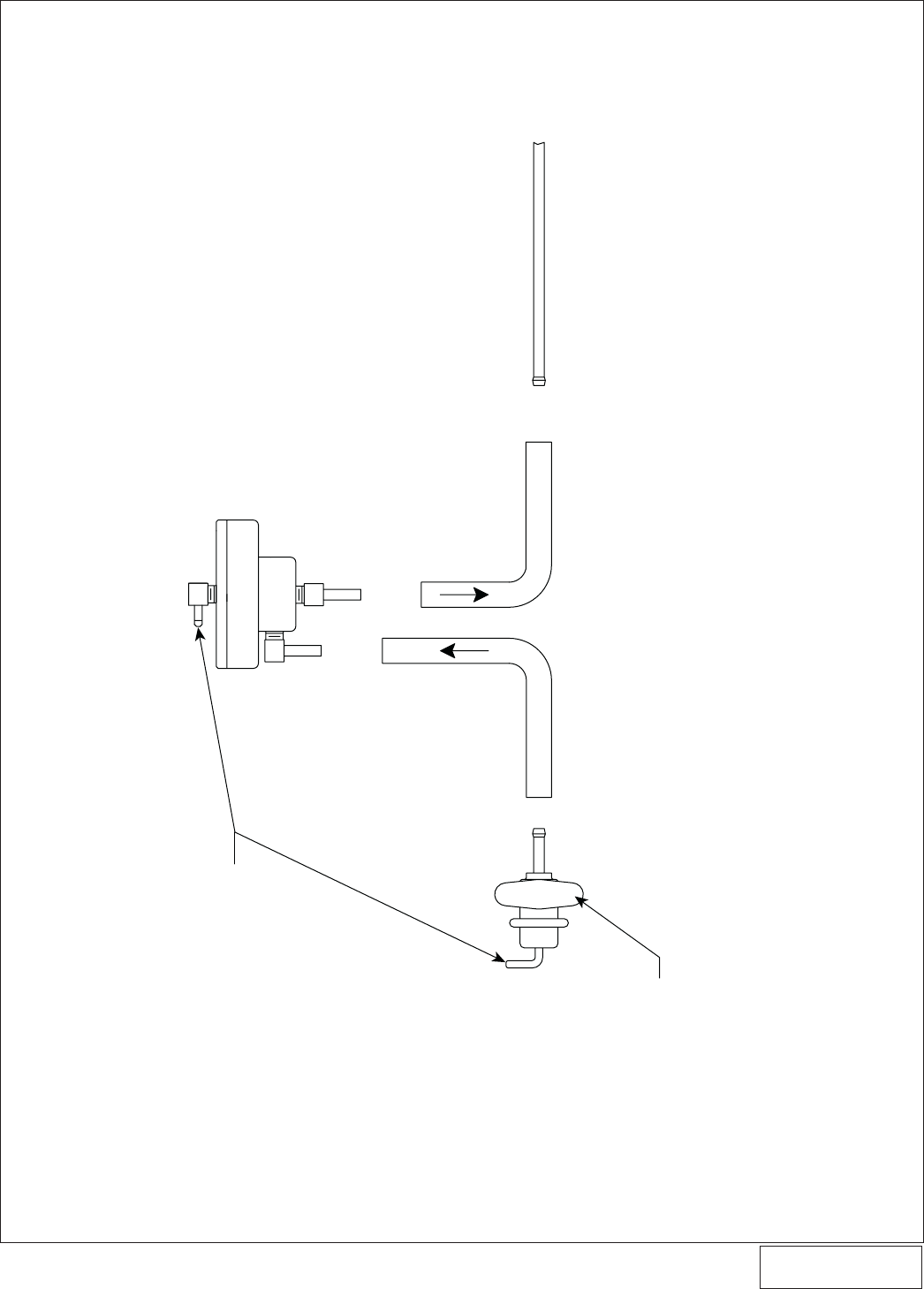
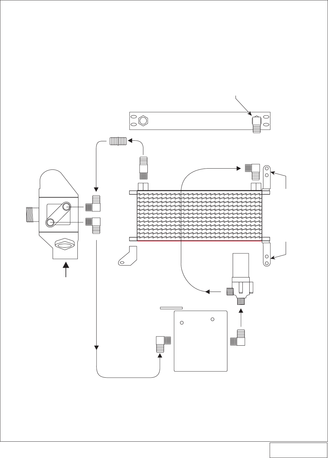
5. FUEL MANAGEMENT UNIT, cont’d.
ATTACH TO MANIFOLD VACUUM
FMU/FUEL LINE DIAGRAM
FUEL PRESSURE
REGULATOR
SUPPLIED 34” FMU
INLET HOSE —
SECURE BOTH
ENDS WITH CLAMPS
SUPPLIED 28” FMU
OUTLET HOSE —
SECURE BOTH
ENDS WITH CLAMPS
FMU OUTLET
FMU INLET
VEHICLE’S STOCK
RETURN LINE
(TO TANK)
Fig. 5-f
P/N: 4HS020-010
©2004 Vortech Engineering, LLC
All Rights Reserved, Intl. Copr. Secured
27JUL04 v2.0 S2000 (4HSv2.0)
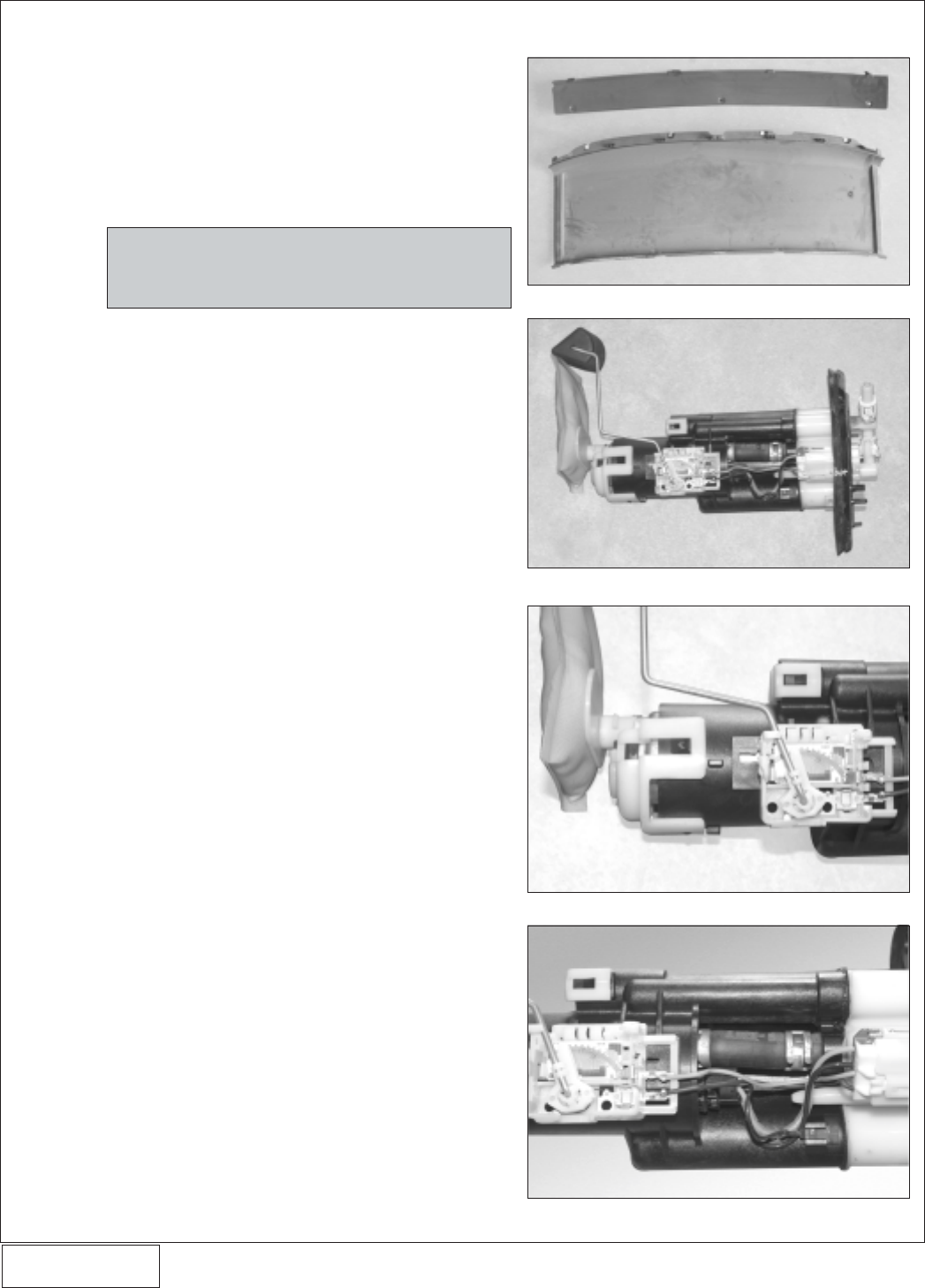
6. FUEL PUMP REPLACEMENT
A. Remove the spare tire from inside the vehicle’s
trunk.
B. Remove the holding tray for the convertible top,
located behind the seats. Remove all of the
pushpins securing the holding tray. (Refer to
page 20-71 of the factory service manual for the
location of all the pushpins) Slide the tray out by
way of the trunk. (See
Fig. 6a.
)
C. Remove the three- (3) screws securing the cover
of the fuel tank.
D. Disconnect the fuel feed and return lines from the
top of the tank along with the electrical connec-
tors.
E. Remove the eight- (8) screws securing the top of
the fuel pump module to the gas tank. Carefully
remove the fuel pump module using care not to
damage the fuel level sender. (See
Fig. 6-b.
)
F. Disconnect the electrical connector connecting
to the fuel pump.
G. Unsnap the white plastic retaining clip next to the
fuel filter. (See
Fig. 6-c.
)
H. Using a pair of pliers, slide the spring clamp on
the short fuel hose down and remove the fuel
pump from the module. (See
Fig. 6-d.
)
I. Carefully remove the small retaining clip secur-
ing the fuel filter to the bottom of the fuel pump.
Remove the fuel filter and attach it to the provided
replacement fuel pump and secure it with the
small retaining clip previously removed.
J. Remove the short fuel line from the discharge of
the fuel pump and install onto the new fuel pump.
K. Reinstall the removed components in reverse
order.
Fig. 6-a
Fig. 6-b
Fig. 6-c
Fig. 6-d
NOTE: Pressing in on the center of the black plas-
tic removable rivets with a small screwdriver
will cause them to release.
10
P/N: 4HS020-010
©2004 Vortech Engineering, LLC
All Rights Reserved, Intl. Copr. Secured
27JUL04 v2.0 S2000 (4HSv2.0)
11
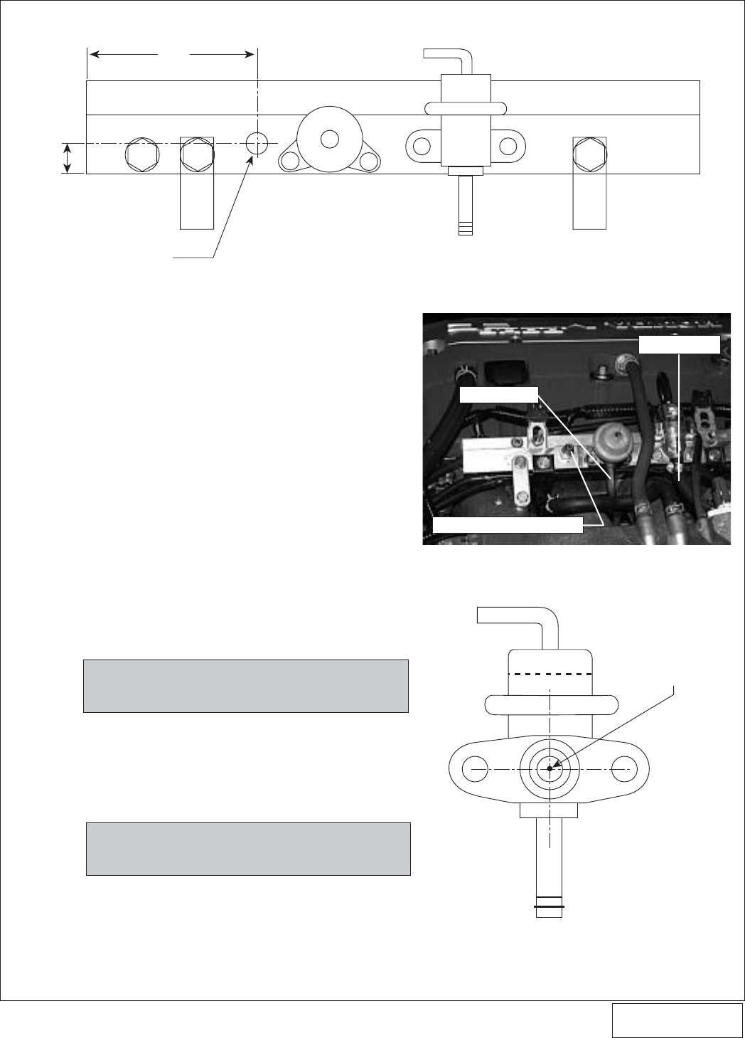
7. FUEL RAIL/REGULATOR MODIFICATIONS (2004 Models Only)
Fig. 7-a
Fig. 7-b
A. Disconnect the fuel feed line running to the
middle of the factory fuel rail.
B. Remove the hose connected to the return side of
the fuel regulator.
C. Loosen the factory screws securing the fuel rail
and remove the fuel rail from the vehicle.
D. Using
Figs. 7-a, 7-b
, mark the location to be
drilled. Keeping the drill perpendicular to the fuel
rail, drill a .339" (R drill bit) hole into the top of the
fuel rail.
E. With a 1/8 NPT tap, thread the newly drilled hole
until the tap is 1/3 of the way inside the hole or the
supplied 1/8 NPT x -4 fitting can be started.
Thoroughly clean all debris from the fuel rail.
F. Using a thread sealant, install the 1/8 NPT end of
the supplied fitting into the fuel rail until the fitting
is snug.
G. Reinstall the fuel rail back into the vehicle. Re-
connect the fuel feed line and secure all the
factory hardware.
NOTE: At this time, leave the fuel return line dis-
connected from the fuel regulator.
H. Remove the two screws securing the fuel pres-
sure regulator to the fuel rail.
I. Following
Fig. 7-c
, drill a .078" hole in the rear of
the regulator. (This allows the regulator to by-
pass more fuel due to increased static fuel pres-
sure.)
NOTE: This step is also recommended for 2001-
2003 model years.
J. Clean all debris and reinstall the fuel pressure
regulator back onto the fuel rail, verifying align-
ment of the O-ring.
K. Reconnect the fuel return line to the bottom barb
on the fuel pressure regulator.
Fig. 7-c
2004 FUEL RAIL
MODIFICATIONS
DRILL WITH AN ‘R’ DRILL
AND TAP 1/8 NPT
4.10"
.60"
FUEL PRESSURE
REGULATOR
DRILL .078" HOLE
RETURN HOSE
FUEL FEED LINE
SUPPLIED -4 x 1/8NPT FITTING
P/N: 4HS020-010
©2004 Vortech Engineering, LLC
All Rights Reserved, Intl. Copr. Secured
27JUL04 v2.0 S2000 (4HSv2.0)
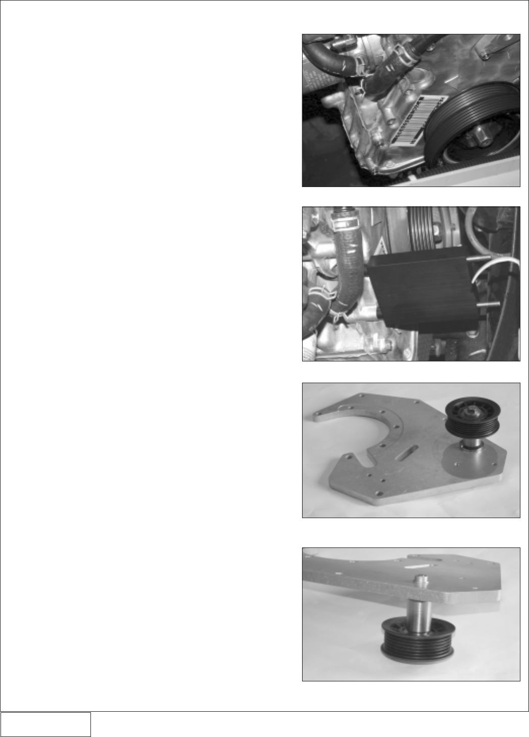
8. SUPERCHARGER MOUNTING BRACKET/PLATE INSTALLATION
Fig. 8-a
Fig. 8-b
Fig. 8-c
Fig. 8-d
A. Detach the factory wiring harness from the rear of
the front crossmember for mounting bracket clear-
ance. Push the harness down toward the steer-
ing rack.
B. Remove the two factory M6 x 1.0 screws from the
passenger side front of the engine near the crank
pulley at the location shown in
Fig. 8-a
.
C. Locate the lower supercharger plate spacer.
This is a .75" thick aluminum spacer that is 2.9"
wide x 4.05" tall with two 1/2" round protrusions
machined into one end. Slide the two supplied 10
mm studs through the holes in the lower plate
spacer. With the studs located loosely through
the lower plate spacer, thread the two studs into
the front cover as shown in
Figs. 8-b, 8-n, 8-o
.
This step must be done as described because of
the limited space available in the engine com-
partment. Use a drop of blue Loctite on the
threads of the studs before threading them into
the engine. Tighten the studs into the front of the
engine by using a stud wrench, or by temporarily
threading two nuts on the end of each stud and
torquing. Remove the nuts from the ends of the
studs.
D. Attach the supplied 6 grooved idler pulley to the
main supercharger mounting plate as shown in
Figs. 8-c, 8-d, 8-e, 8-f
. Slide one of the supplied
3/8-24 x 3.5" screws through the machined bear-
ing pilot, 6 groove idler pulley and steel idler
spacer (1.772" effective length x Ø.406" through
hole). Attach the complete assembly to the alu-
minum mounting plate by threading the 3/8-24 x
3.5" screw through the plate and into the threaded
steel insert that is pressed into the plate.
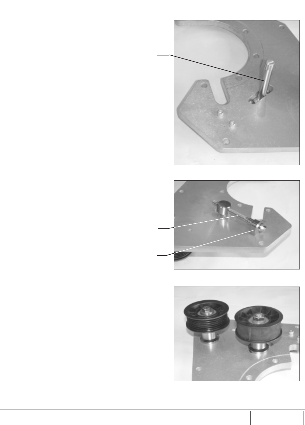
E. Attach the belt tensioner adjustment screw,
tensioner arbor and adjustment screw locator
block to the supercharger mounting plate as
shown in
Figs. 8-e, 8-f, 8-g, 8-h, 8-i
. Secure the
assembly to the plate by threading the two 1/4-20
x .75" socket head screws through the plate and
into the adjustment screw locator block as shown.
Make sure the locator block is positioned as
shown in
Fig. 8-h
or you will experience oil feed
line clearance issues.
F. Slide the supplied smooth idler pulley and steel
idler spacer (1.772" effective length x Ø.515"
through hole) over the tensioner arbor that was
previously installed onto the mounting plate.
Install the 12 mm washer and 1/2-20 jam lock nut
over the idler and arbor. Do not tighten the nut at
this time. (See
Fig. 8-f.
)
G. Remove the blue plastic dust cap located on the
1/2" oil drain fitting on the bottom of the super-
charger. Attach the supplied 1/2" x 18" fabric
braided oil drain hose to the supercharger drain
12
P/N: 4HS020-010
©2004 Vortech Engineering, LLC
All Rights Reserved, Intl. Copr. Secured
27JUL04 v2.0 S2000 (4HSv2.0)
REMOVE FACTORY
SCREWS
13
8. SUPERCHARGER MOUNTING BRACKET/PLATE INSTALLATION, cont’d.
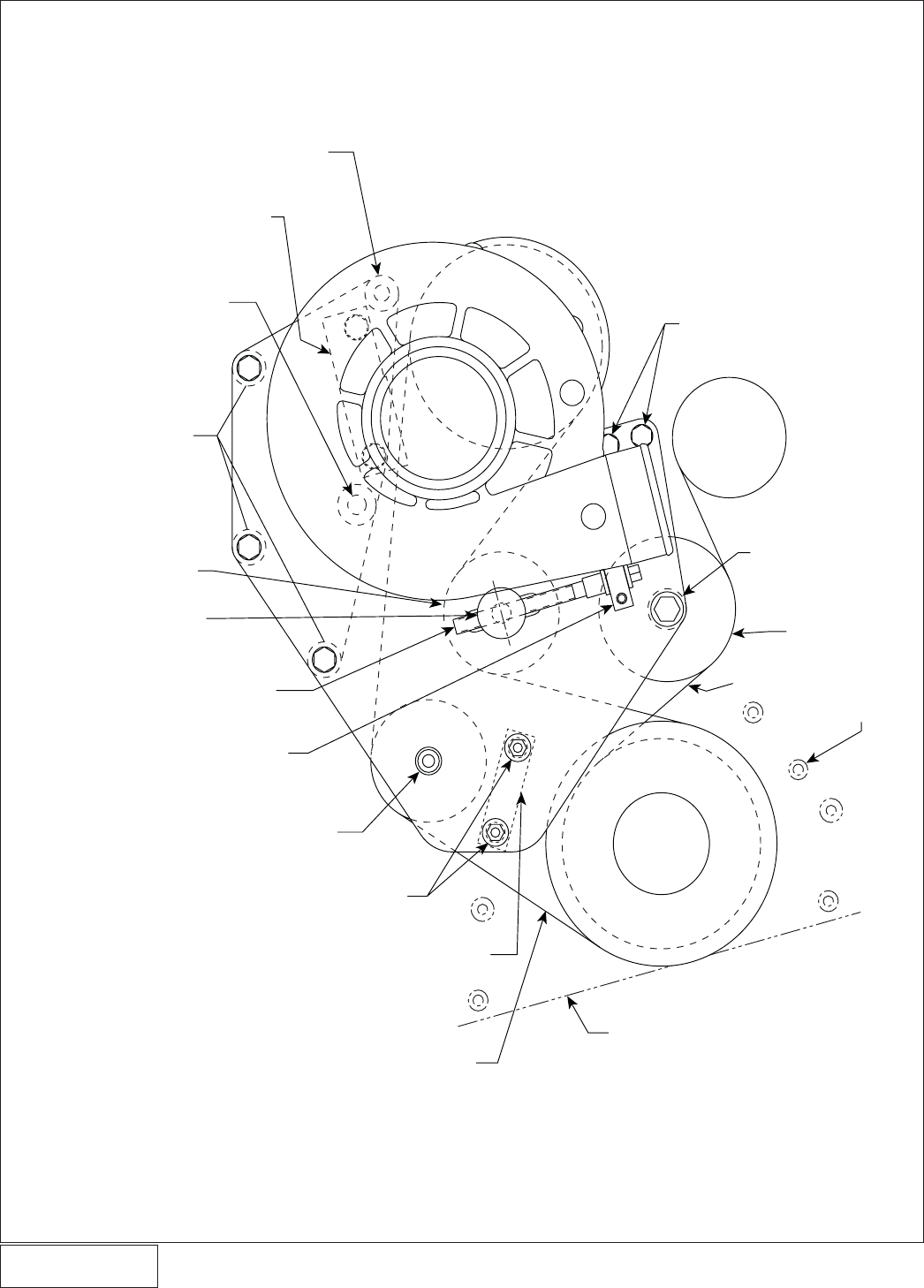
DO NOT INSTALL HARDWARE
IN THIS HOLE AT THIS STEP
M12 x 1.75 x 50mm SCREW WITH
WASHER INSTALLED THROUGH
SUPPORT PLATE AND Ø1.0 x .549
SPACER AND INTO SUPERCHARGER
BOSS (SPACER SANDWICHED
BETWEEN CENTER SUPERCHARGER
BOSS AND SUPPORT PLATE)
3/8-16 x 1.25 SCREW
WITH AN WASHER
3/8-24 x 3.5" SCREW/
BEARING PILOT
INSTALLED THROUGH
RIBBED IDLER AND
SPACER AND INTO
THE NUT INSTALLED
IN THE MAIN PLATE
(SEE SIDE VIEW)
BELT TENSIONER
ADJUSTMENT SCREW
AND LOCATOR BLOCK
(LOCATED ON OPPOSITE
SIDE OF PLATE) ATTACHED
WITH TWO 1/4-20 x .75
SH SCREWS THREADED
IN FROM THIS SIDE
OF MAIN PLATE
MAIN SUPERCHARGER
MOUNTING PLATE
1/2-20 BELT TENSIONER
ARBOR SCREW
INSTALLED (FROM
OTHER SIDE)
THROUGH MAIN
PLATE IDLER SPACER
SMOOTH IDLER - M12
x 10" THICK WASHER
AND 1/2-20 JAM LOCK
NUT (SEE SIDE VIEW)
MAIN SUPERCHARGER MOUNTING PLATE
VIEW FROM BACKSIDE
(DASHED LINES REVEAL HIDDEN VIEWS)
Fig. 8-e
P/N: 4HS020-010
©2004 Vortech Engineering, LLC
All Rights Reserved, Intl. Copr. Secured
27JUL04 v2.0 S2000 (4HSv2.0)
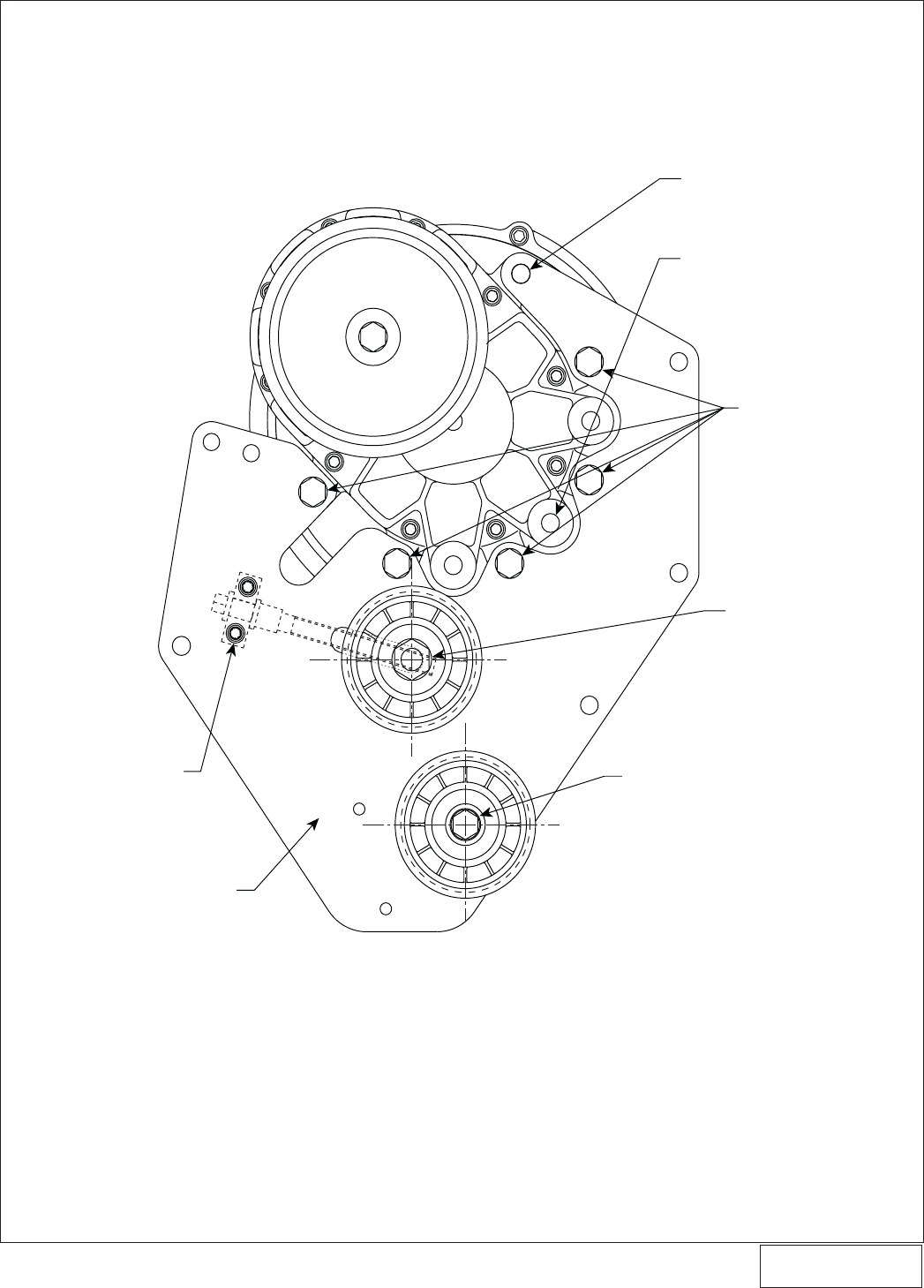
14
BELT
TENSIONER
ARBOR
MAIN SUPERCHARGER
MOUNTING PLATE
PRE-INSTALLED
3/8-24 “PRESS
NUT” INSERT
RIBBED IDLER
SPACER Ø.406
INSIDE DIAMETER
MAIN SUPERCHARGER MOUNTING PLATE
VIEW FROM PASSENGER SIDE
RIBBED IDLER
PULLEY - Ø3.0
SMOOTH IDLER
SPACER - Ø.515
INSIDE DIAMETER
SMOOTH IDLER
PULLEY - Ø3.0
M12 x .10” THICK WASHER
1/2-20 JAM LOCKNUT
(DO NOT TIGHTEN
UNTIL LAST STEP)
3/8-24 x 3.5"
SCREW
BEARING PILOT - Ø.386
INSIDE DIAMETER
1.772
1.772
Fig. 8-f
8. SUPERCHARGER MOUNTING BRACKET/PLATE INSTALLATION, cont’d.
P/N: 4HS020-010
©2004 Vortech Engineering, LLC
All Rights Reserved, Intl. Copr. Secured
27JUL04 v2.0 S2000 (4HSv2.0)
15
8. SUPERCHARGER MOUNTING BRACKET/PLATE INSTALLATION, cont’d.
Fig. 8-g
Fig. 8-i
Fig. 8-h
BELT TENSIONER
ARBOR SCREW
BELT TENSIONER
ADJUSTMENT SCREW
ADJUSTMENT SCREW
LOCATOR BLOCK
P/N: 4HS020-010
©2004 Vortech Engineering, LLC
All Rights Reserved, Intl. Copr. Secured
27JUL04 v2.0 S2000 (4HSv2.0)
16
fitting. Secure with a #8 hose clamp. Make sure
that the hose clamp housing is clocked down
toward the supercharger so that it will not cause
interference with the supercharger mounting plate
that is to be installed. (See
Fig. 8-j
.)
H. Remove the blue plastic dust cap located on the
brass oil feed nozzle on the side of the super-
charger. Thread the supplied steel 1/8" NPT x
45° x –4JIC fitting into the supercharger oil feed
nozzle. Carefully tighten and clock the 45° fitting
as shown in
Figs. 8-j, 8-k
. Use caution when
tightening the oil feed fitting, as the brass nozzle
may be broken if care is not exercised. Connect
the supplied oil feed line to the flare fitting.
Temporarily cover the open end from debris until
the connection is made to the engine in step 12.
I. Attach the supercharger unit to the mounting
plate as shown using the five supplied 3/8-16 x
1.25" screws with AN washers. The sixth super-
charger mounting hole should remain empty at
this time. (Refer back to
Fig. 8-e, and Fig. 8-k
.)
J. Using two of the supplied 3/8-16 x 1.25" screws
with AN washers, attach the upper supercharger
support plate to the supercharger mounting block
as shown in
Figs. 8-l, 8-m
. Thread the screws
down until the heads almost touch the plate/
washers. Do not tighten the screws at this time.
K. From the back side, slide the supplied 3/8-16 x
3.5" screw and AN washer through the top hole
(refer to
Figs. 8-n, 8-o
) of the upper support plate
and into one of the supplied Ø.875 O.D. x 1.858"
long spacers. Loosely mount the support plate
assembly with spacer onto the supercharger and
previously assembled main supercharger plate.
Fig. 8-J
Fig. 8-K
NOTE: When directed, it is important to follow the
suggestion: “Do not tighten the screws”.
Failure to follow this direction will result in
bracket misalignment and the possibility of
the VTEC solenoid not maintaining a proper
seal. Thread the applicable screws and nuts
in until the head almost touches down (.01-
.02" clearance). This will allow the bracket
to properly align itself to the engine and
other components in the assembly during
installation.
NOTE: Use only clean engine oil on the pipe
threads. Teflon tape or pipe sealant is not
recommended as it might loosen and cause
blockage of the small oil feed orifice result-
ing in possible supercharger failure.
8. SUPERCHARGER MOUNTING BRACKET/PLATE INSTALLATION, cont’d.
Fig. 8-l
NO FASTENER HERE AT THIS TIME
3/8-16 x 1.25
SCREWS WITH AN
WASHERS (DO NOT
TIGHTEN)
P/N: 4HS020-010
©2004 Vortech Engineering, LLC
All Rights Reserved, Intl. Copr. Secured
27JUL04 v2.0 S2000 (4HSv2.0)
17
SUPERCHARGER SUPPORT PLATE
VIEW FROM FRONT (BEFORE
JOINING TO MAIN PLATE
ASSEMBLY)
PRE-INSTALLED 3/8
-24 “PRESS NUT”
INSERT (LOCATED
ON BACKSIDE OF
PLATE)
SUPERCHARGER
SUPPORT PLATE
3/8-16 x 1.25 SCREWS WITH
AN WASHERS (DO NOT
TIGHTEN SCREWS UNTIL
ENTIRE BRACKET
ASSEMBLY IS MOUNTED
ONTO ENGINE)
HOLE FOR M12 x 1.75 x
50mm SCREW (INSTALLED
FROM BACKSIDE)
SUPERCHARGER PLATE
MOUNTING BLOCK
(SANDWICHED BETWEEN
VTEC SOLENOID AND
CYLINDER HEAD)
Fig. 8-m
8. SUPERCHARGER MOUNTING BRACKET/PLATE INSTALLATION, cont’d.
P/N: 4HS020-010
©2004 Vortech Engineering, LLC
All Rights Reserved, Intl. Copr. Secured
27JUL04 v2.0 S2000 (4HSv2.0)
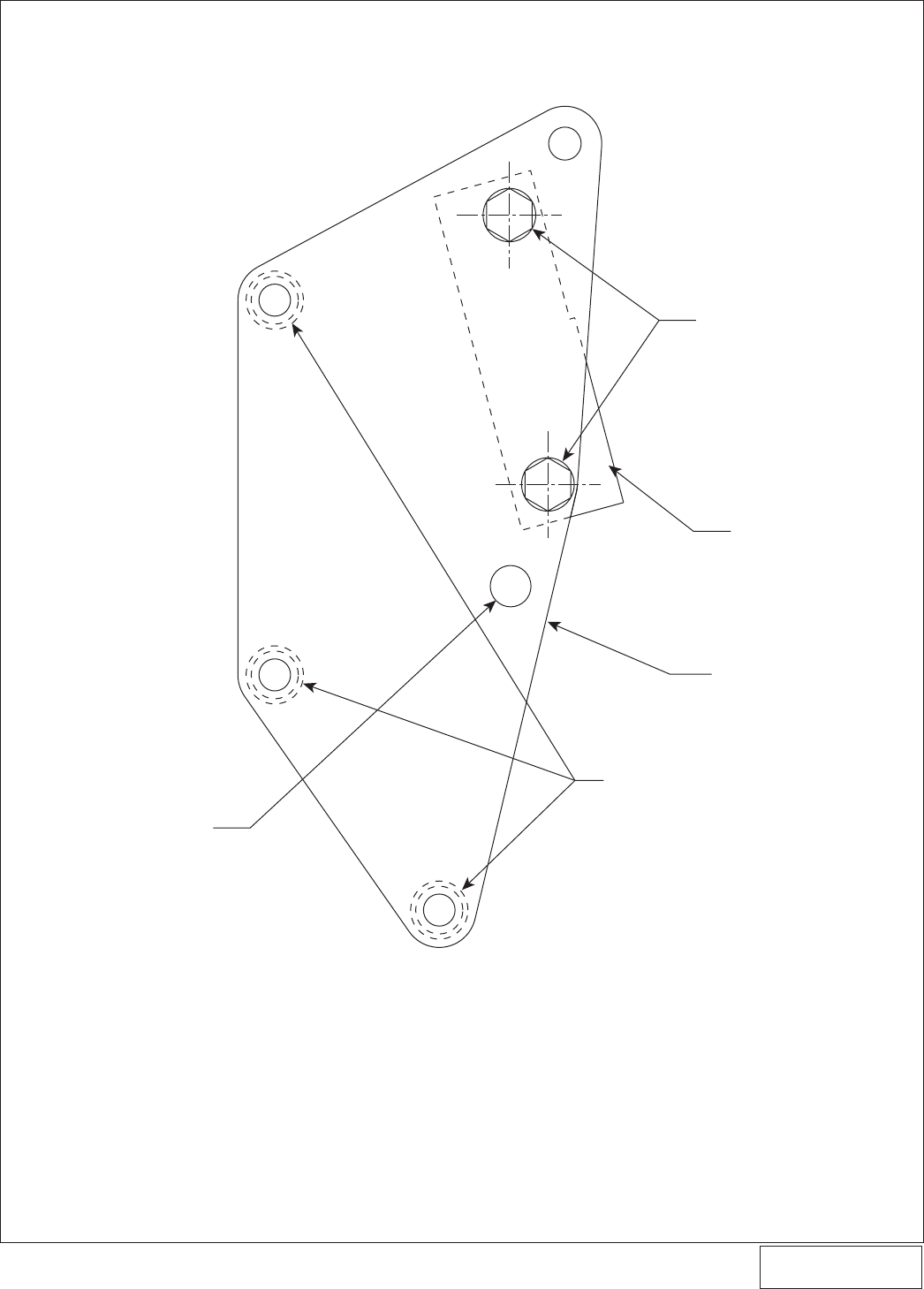
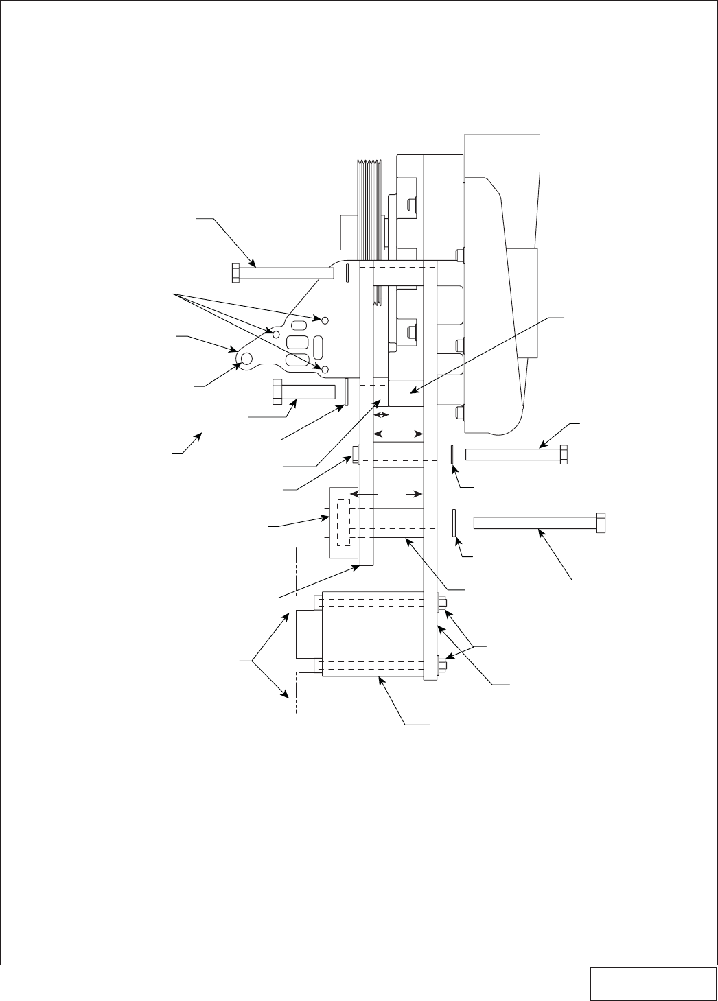
Fig. 8-n
SUPERCHARGER PLATE MOUNTING
BLOCK (SANDWICHED BETWEEN
VTEC SOLENOID AND CYLINDER HEAD)
3/8-16 x 3/5” SCREW/AN WASHER INSTALLED
FROM THE BACKSIDE THROUGH SUPPORT
PLATE AND Ø.875 x 1.858 SPACER AND INTO
SUPERCHARGER (SPACER SANDWICHED
BETWEEN MAIN PLATE AND SUPPORT PLATE)
M12 x 1.75 x 50mm SCREW WITH
WASHER INSTALLED FROM THE
BACKSIDE - THROUGH SUPPORT
PLATE AND Ø1.0 x .549 SPACER
AND INTO SUPERCHARGER
(SPACER SANDWICHED BETWEEN
CENTER SUPERCHARGER BOSS
AND SUPPORT PLATE)
Ø3.0” SUPERCHARGER
TENSIONER PULLEY
(SMOOTH)
BELT TENSIONER ARBOR
3/8-24 x 3.5” SCREWS/AN
WASHERS INSTALLED
FROM THE FRONT -
THROUGH MAIN PLATE
AND Ø.875 x 1.858
SPACERS AND INTO
SUPPORT PLATE (SPACERS
SANDWICHED BETWEEN
MAIN PLATE AND SUPPORT
PLATE)
BELT TENSIONER ADJUSTMENT SCREW
ADJUSTMENT SCREW AND LOCATOR
BLOCK ATTACHED WITH TWO 1/4-20 x .75
SH SCREWS THREADED IN FROM THE
BACK SIDE OF MAIN PLATE
3/8-24 x 3.5 SCREW/BEARING PILOT INSTALLED
FROM THE BACKSIDE THROUGH RIBBED
IDLER AND SPACER AND INTO “PRESSED NUT”
INSERT INSTALLED IN MAIN PLATE
M6 x 1.0 NUTS WITH WASHERS INSTALLED
ONTO STUDS PREVIOUSLY THREADED INTO
FRONT OF ENGINE (REMOVE FACTORY
HARDWARE)
LOWER SUPERCHARGER PLATE SPACER (ROUND
PROTRUSIONS TO BE INSTALLED AGAINST THE
FRONT COVER)
SUPERCHARGER DRIVE BELT
FRONT VIEW OF ENGINE
(DASHED LINES REVEAL HIDDEN VIEWS)
5/16-18 x 1.0 SCREWS
WITH AN WASHERS
THROUGH MAIN PLATE
INTO LATERAL SUPPORT
PLATE
FACTORY
SPRING
TENSIONER
M10 x 1.25 x 115 SCREW
WITH WASHER THROUGH
MAIN PLATE - Ø1.0 x
Ø2.726 SPACER, FACTORY
IDLER AND INTO FACTORY
THREADED IDLER
MOUNTING HOLE
ON FRONT COVER
FACTORY FIXED
IDLER
FACTORY
BELT
FACTORY
BOSSES
LOCATED ON
ENGINE FRONT
COVER
OIL PAN FLANGE
CRANK
PULLEY
8. SUPERCHARGER MOUNTING BRACKET/PLATE INSTALLATION, cont’d.
18
P/N: 4HS020-010
©2004 Vortech Engineering, LLC
All Rights Reserved, Intl. Copr. Secured
27JUL04 v2.0 S2000 (4HSv2.0)
19
3/8-16 x 3.5” SCREW / AN WASHER
INSTALLED FROM THE BACKSIDE
THROUGH SUPPORT PLATE AND
Ø.875 x 1.858 SPACER AND INTO
UPPER SUPERCHARGER MOUNTING
BOSS (SPACER SANDWICHED BETWEEN
MAIN PLATE AND SUPPORT PLATE)
M6 1.0 x 80mm SCREWS
THROUGH VTEC SOLENOID
(NOT SHOWN), SUPERCHARGER
PLATE MOUNTING BLOCK
AND INTO CYLINDER HEAD)
CYLINDER HEAD
M10 x 1.25 x 50mm SCREW
WITH WASHER THROUGH
SUPERCHARGER PLATE MOUNTING
BLOCK AND INTO CYLINDER HEAD
SUPERCHARGER PLATE
MOUNTING BLOCK
M12 x 1.75 x 50 SCREW
FACTORY FIXED IDLER
PRE-INSTALLED 3/8-24
“PRESS NUT” INSERT (3 PLACES)
M12 WASHER
Ø1.0” x .549 SPACER
SUPERCHARGER
SUPPORT PLATE
FRONT FACE OF
ENGINE BLOCK
SUPERCHARGER BRACKET ASSEMBLY VIEW FROM PASSENGER SIDE —
VORTECH IDLERS AND SOME FASTENERS NOT SHOWN FOR CLARITY
(DASHED LINES REVEAL HIDDEN VIEWS)
LOWER SUPERCHARGER PLATE SPACER
(ROUND PROTRUSIONS TO BE INSTALLED
AGAINST THE FRONT COVER)
SUPERCHARGER
MOUNTING PLATE
M6 x 1.25 x 1.15 SCREW
THROUGH MAIN PLATE.
Ø1.0 x 2.726 SPACER
FACTORY IDLER AND
INTO FACTORY
THREADED IDLER
MOUNTING HOLE
ON FRONT COVER
3/8-24 x 3.5’ SCREWS
INSTALLED FROM THE
FRONT THROUGH MAIN
PLATE AND Ø.875 x 1.858
SPACERS AND INTO
SUPPORT PLATE, SPACERS
SANDWICHED BETWEEN
MAIN PLATE AND SUPPORT
PLATE — 3 PLACES)
CENTER M12
SUPERCHARGER BOSS
3/8"
WASHER
Ø1.0" x 2.726
STEEL SPACER
M10
WASHER
M6 x 1.0 NUTS WITH WASHERS INSTALLED
ONTO STUDS PREVIOUSLY THREADED
INTO FRONT OF ENGINE
1.858
2.726
.549
8. SUPERCHARGER MOUNTING BRACKET/PLATE INSTALLATION, cont’d.
Fig. 8-o
P/N: 4HS020-010
©2004 Vortech Engineering, LLC
All Rights Reserved, Intl. Copr. Secured
27JUL04 v2.0 S2000 (4HSv2.0)
20
The 3/8-16 x 3.5" screw is to be threaded through
the main supercharger plate and into the remain-
ing 3/8" threaded mounting hole on the super-
charger unit. (See
Fig. 8-p
.) Thread the screw
down until the head almost touches the plate/
washer. Do not tighten the screw at this time.
L. Mount the remaining three Ø.875 O.D. x 1.858"
long spacers between the main supercharger
mounting plate and the upper support plate as
shown in
Figs. 8-P, 8-q
. From the front side, slide
the three supplied 3/8-24 x 3.5" screws and AN
washers through the main mounting plate, through
the three Ø.875 O.D. x 1.858" long spacers and
into the threaded steel inserts that are pressed
into the back side of the support plate. (See
Figs.
8-n, 8-o
.) Thread the screws down until the
heads almost touch the plate/washers. Do not
tighten the screws at this time.
M. From the back side, slide the supplied M12 x 1.75
x 50 screw and M12 washer through the remain-
ing hole in the upper support plate (refer to
Figs.
8-o, 8-q.
) and into the supplied Ø1.0 O.D. x .549"
long spacer. The spacer is to be sandwiched
between the front side of the upper support plate
and the center 12 mm boss located on the
supercharger cover. Thread the screw down
until the head almost touches the plate/washer.
Do not tighten the screw at this time.
N. From the front side, slide the supplied M10 x 1.25
x 115 screw and M10 washer through the re-
maining hole in the mounting plate and into the
supplied Ø1.0 O.D. x 2.726" long steel spacer.
(See
Figs. 8-r, 8-s
.)
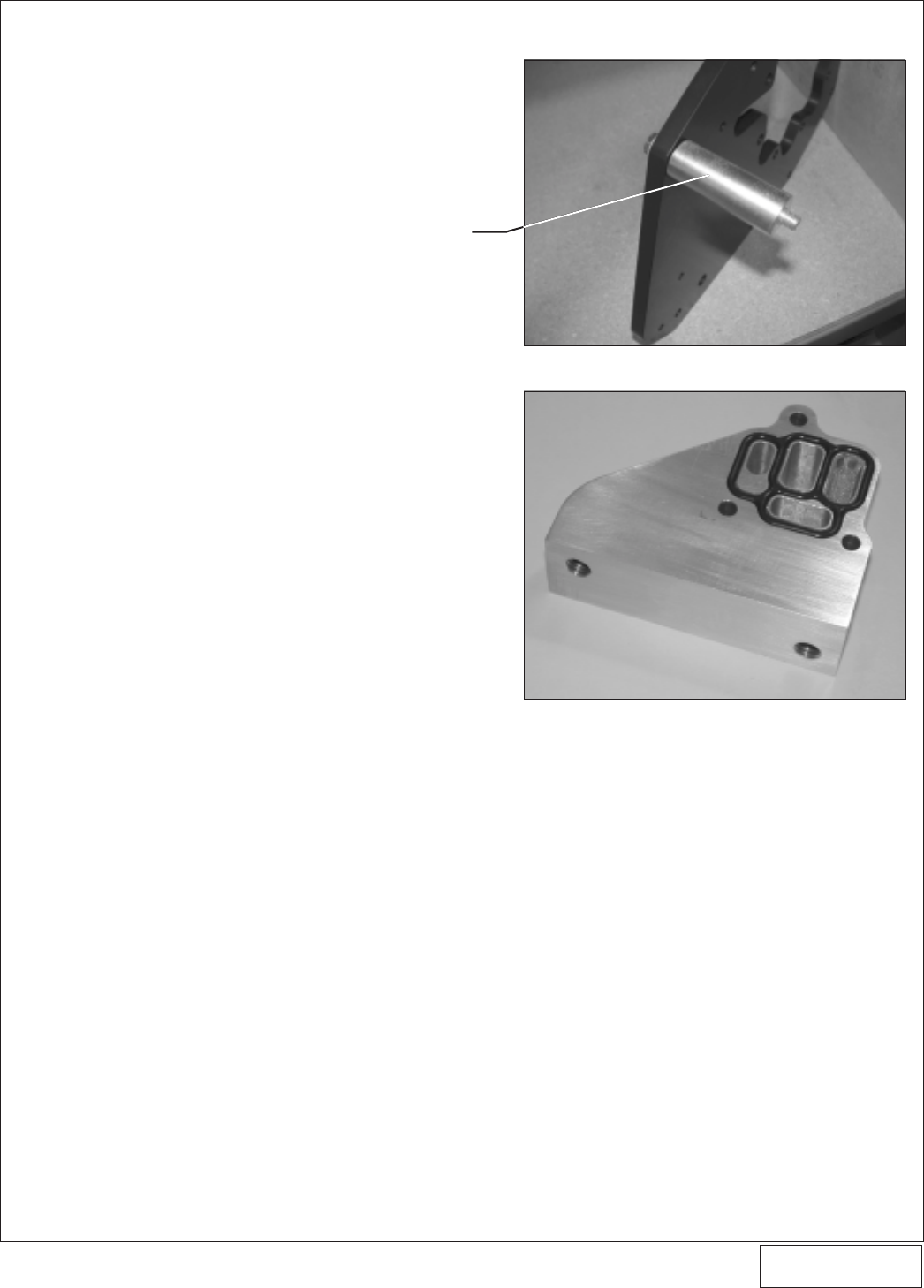
O. Insert the new supplied VTEC o-ring gasket seal
into grooves in the Vortech supercharger plate
mounting block. as shown in
Fig. 8-t
. Make sure
that the gasket remains in the block grooves
during bracket installation on the engine. Apply a
light amount of oil to the gasket.
P. Place the factory idler (removed in step one)
back onto the original boss on the front of the
engine (without hardware, washer or dust shield).
Q. Loosely route the factory accessory belt onto the
engine. The belt should be routed around the
crank pulley and fixed idler pulley per the factory
method. Do not attempt route the belt around the
spring tensioner at this time.
R. Loosely route the supplied supercharger drive
belt onto the engine. Following
Fig. 8-n
, loosely
attach the supercharger with bracket assembly
onto the engine. Line up the two Ø1/4" holes in
the main bracket with the lower spacer and two
M6 studs (previously installed). Move the bracket
assembly over the studs. Thread the supplied
M6 nuts with washers over the ends of the studs
until the nuts almost touch the washers. Do not
tighten the nuts at this time.
8. SUPERCHARGER MOUNTING BRACKET/PLATE INSTALLATION, cont’d.
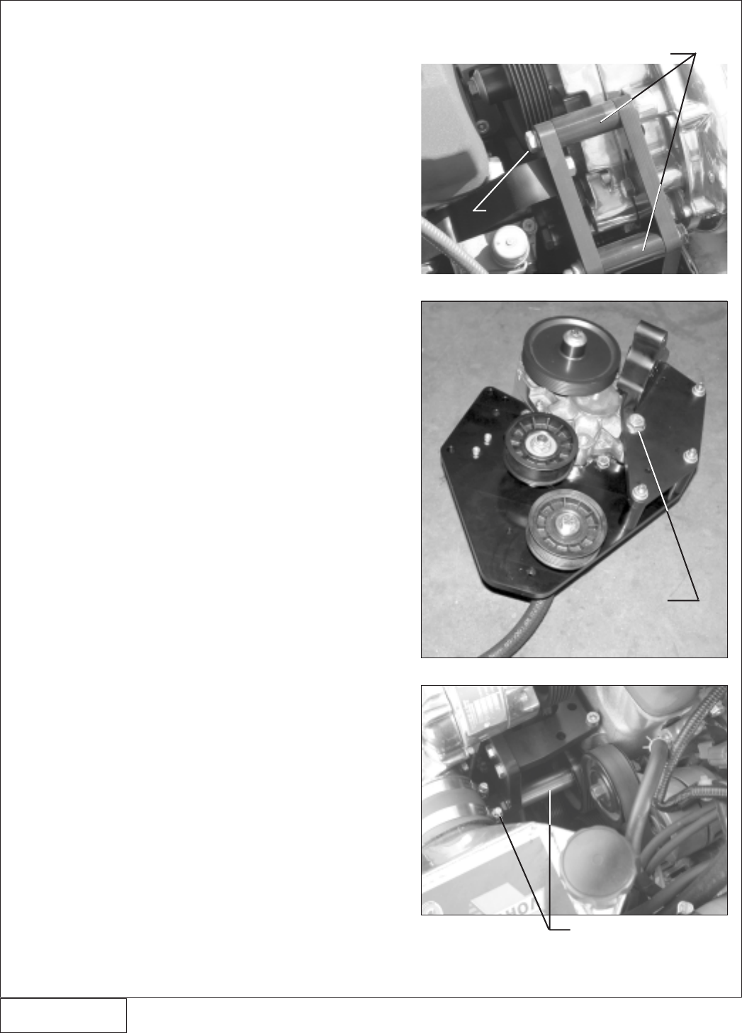
Fig. 8-p
Fig. 8-q
Fig. 8-r
3/8-16 x 3.5 SCREW
INTO SUPERCHARGER
M12 x 1.75 x 50
SCREW/WASHER
M10 x 1.25 x 115 SCREW
WITH Ø2.726” SPACER
Ø.875 x 1.858 SPACERS (4x)
P/N: 4HS020-010
©2004 Vortech Engineering, LLC
All Rights Reserved, Intl. Copr. Secured
27JUL04 v2.0 S2000 (4HSv2.0)
21
8. SUPERCHARGER MOUNTING BRACKET/PLATE INSTALLATION, cont’d.
Fig. 8-s
Fig. 8-t
SLIDE THE Ø1.0” x 2.726”
SPACER ONTO THE M10
x 1.25 x 115 SCREW
BEFORE ATTACHING
THE MOUNTING PLATE
TO THE ENGINE
P/N: 4HS020-010
©2004 Vortech Engineering, LLC
All Rights Reserved, Intl. Copr. Secured
27JUL04 v2.0 S2000 (4HSv2.0)
22
S. Align the M10 x 1.25 x 115 screw (previously
inserted through the front of the main super-
charger plate) into the factory idler pulley mount
on the front cover. (See
Fig. 8-u
.) Make sure that
the supplied Ø1.0 O.D. x 2.726" long spacer is
sandwiched between the back of the super-
charger mounting plate and the inner bearing
race of the factory idler. Do not tighten any
screws at this time.
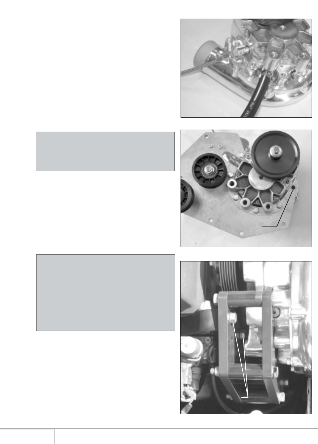
T. Insert the three supplied M6 x 1.0 x 80 screws
with washers through the previously removed
VTEC solenoid, the Vortech supercharger plate
mounting block and into the side of the cylinder
head. (See
Figs. 8-v, 8-w
.) Make sure that both
of the VTEC gaskets remain in their proper
locations during bracket installation on the en-
gine. Thread the supplied M10 x 1.25 x 50 screw
with washer into the remaining hole in the super-
charger plate mounting block and into the cylin-
der head. Thread the four screws down until the
heads almost touch the washers. Do not tighten
the screws at this time.
U. Attach the supplied lateral supercharger mount-
ing plate (‘L’ shaped bracket) support to the front
corner of the cylinder head as shown using the
supplied M8 x 1.25 x 45 socket head screws (no
washers are used here). See
Figs. 8-u, 8-x
.
Thread the screws down until the heads almost
touch the plate. Do not tighten the screws.
V. Align the two threaded holes in the end of the
lateral support with the two holes in the super-
charger mounting plate. Slide the two supplied
5/16-18 x 1.0" screws with AN washers through
the remaining two holes in the supercharger
mounting plate and into the lateral support. Thread
the screws down until the heads almost touch the
washers. Do not tighten the screws at this time.
W. Secure the completed mounting bracket assem-
bly to the engine by lightly “snugging” the hard-
ware in the following sequence:
1. Four VTEC solenoid mounting screws.
2. 3/8-16 x 3.5" screw running through the top
hole of the upper support plate, Ø.875 O.D.
x 1.858" long spacer and into the super-
charger.
3. M12 x 1.75 x 50 screw running through the
upper support plate, Ø1.0 O.D. x .549"
spacer and into the center 12 mm boss
NOTE: When installing the supercharger with bracket
assembly onto the engine, the belt must be
manipulated so that it is properly routed
around the idler, tensioner, supercharger
pulley and lower supercharger plate spacer.
(Refer back to Fig. 7-n.)
8. SUPERCHARGER MOUNTING BRACKET/PLATE INSTALLATION, cont’d.
Fig. 8-u
Fig. 8-v
Fig. 8-w
LATERAL MOUNTING PLATE
M10 x 1.25 x 50

P/N: 4HS020-010
©2004 Vortech Engineering, LLC
All Rights Reserved, Intl. Copr. Secured
27JUL04 v2.0 S2000 (4HSv2.0)
23
located on the supercharger cover.
4. Two 3/8-16 x 1.25" screws with AN washers
that attach the supercharger support plate
to the supercharger mounting block.
5. M10 x 1.25 x 115 screw through the front of
the supercharger mounting plate and into
the factory idler pulley mount on the front
cover.
6. Two 5/16-18 x 1.0" screws through the su-
percharger mounting plate and into the lat-
eral support.
7. Two M8 x 1.25 x 45 socket head screws
through the lateral support mounting plate,
front corner of the cylinder head and into the
front cover.
8. Three 3/8-24 x 3.5" screws running through
the main mounting plate, Ø.875 O.D. x
1.858" long spacers and into the threaded
steel inserts that are pressed into the back
side of the support plate.
9. Two M6 nuts that are threaded onto the two
studs inserted into the front of the engine.
X. Repeat the sequence above with final torquing of
all hardware.
Y. Reconnect the previously removed VTEC wiring
connections.
Z. Reattach the plastic vacuum canister to the back-
side of the front crossmember (located in front of
the engine) using the factory screw that was
removed in step 1. Make sure that there is
enough clearance between the vacuum hose
and the crank pulley.
8. SUPERCHARGER MOUNTING BRACKET/PLATE INSTALLATION, cont’d.
Fig. 8-x
TWO M8 x 1.25 x 45
SOCKET HEAD SCREWS
(NO WASHERS)
TWO 5/16-18 x 1"
SCREWS WITH
AN WASHERS
P/N: 4HS020-010
©2004 Vortech Engineering, LLC
All Rights Reserved, Intl. Copr. Secured
27JUL04 v2.0 S2000 (4HSv2.0)
24
9. SUPPLEMENTARY FUEL INJECTOR INSTALLATION (2004 Models Only)
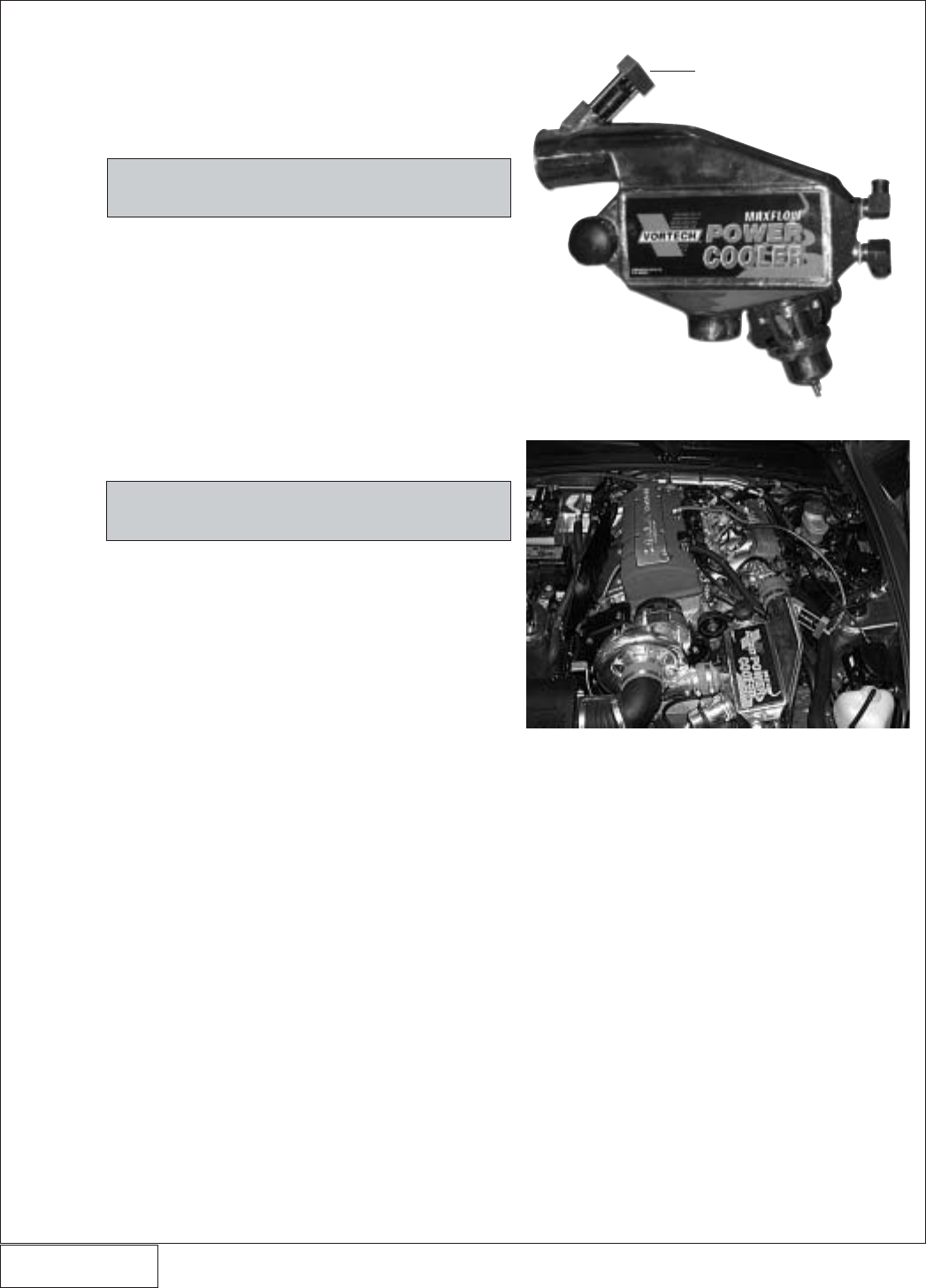
A. Locate the supplied charge cooler. Insert the
supplied 55lb/hr fuel injector into the injector
base welded to the cooler discharge tube so that
the injector plug is facing away from the injector
base. (See
Fig. 9-a
.)
NOTE: Lightly oil the O-rings on the injector for
easier installation.
B. Insert the upper block over the injector. Secure
the upper injector block with the supplied shoul-
der bolts.
C. Install the 1/8 NPT end of the supplied 90° fitting
into the upper injector block. Orient the fitting so
that it is pointing toward the back of the car.
D. Connect the 90° end of the supplied steel braided
line to the -4 end on the installed straight fitting in
the fuel rail. Run the fuel line toward the front of
the car. Leave the open end of the fuel line
disconnected until the charge cooler has been
installed. (See
Fig. 9-b
.)
NOTE: Thread sealant is recommenced on all fit-
ting ends that have pipe threads.
Fig. 9-a / TOP VIEW
Fig. 9-b / TOP VIEW
INSTALLED INJECTOR
P/N: 4HS020-010
©2004 Vortech Engineering, LLC
All Rights Reserved, Intl. Copr. Secured
27JUL04 v2.0 S2000 (4HSv2.0)
25
10. SUPERCHARGER BELT TENSIONER ADJUSTMENT
A. Make sure that the 1/2-20 jam lock nut previously
threaded onto the tensioner arbor is threaded
down almost all of the way, but not tight. The belt
is tightened/loosened by rotating the belt tensioner
adjustment screw. Tighten the belt until light
resistance is felt in the belt tensioner adjustment
screw. Proper belt tension is achieved when the
belt can be twisted approximately 1/4 of a turn by
hand. Adjust belt tension as needed. Do not over
tension the belt.
B. From beneath the vehicle, tighten the 1/2-20 jam
lock nut on the belt tensioner arbor.
C. Reinstall the factory accessory belt using the
factory routing.
11. AIR PUMP INLET HOSE MODIFICATION
A. Separate the air pump inlet hose from the factory
hose union that was originally connected to the
engine inlet duct.
B. Insert the supplied 3/4" air pump inlet hose filter
into the pump inlet hose. (See
Figs. 11-a, 11-b
.)
Fig. 11-a / TOP VIEW
Fig. 11-b / BOTTOM VIEW
SUPPLIED AIR PUMP
INLET FILTER
SUPPLIED AIR PUMP
INLET FILTER
P/N: 4HS020-010
©2004 Vortech Engineering, LLC
All Rights Reserved, Intl. Copr. Secured
27JUL04 v2.0 S2000 (4HSv2.0)
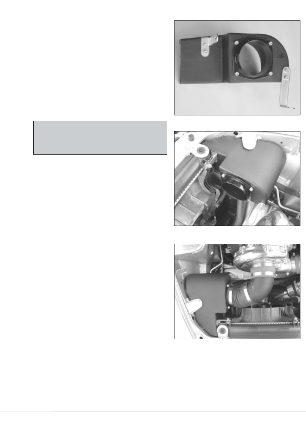
12. CHARGE AIR COOLER INSTALLATION
A. Attach the supplied breather/filter to the outlet of
the Vortech race bypass valve. Attach the Vortech
race bypass valve to the charge cooler core
using the supplied 1/4-20 x .50" socket head
bolts and gasket. (See
Fig. 12-a
.)
B. Install the charge cooler between the super-
charger and the throttle body using the supplied
2.75" sleeves and #44 hose clamps. The 3" long
sleeve is to be placed on the throttle body.
C. Remove all of the plastic valance or splash
panels located under the vehicle toward the
front.
D. Install the fittings into the water cooler as shown
in
Fig. Diag 12-b, and Fig. 12-d
. Note that the 90°
fitting is to be pointing toward the front of the
vehicle when the water cooler is mounted.
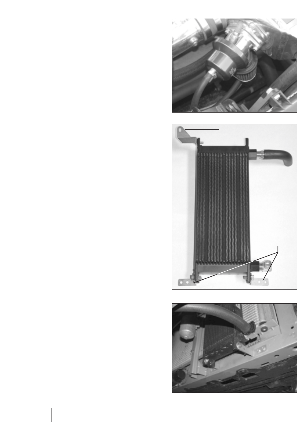
E. Attach the water cooler mounting bracket #1 to
the upper portion of the cooler using the 1/4"
hardware as shown.
F. Trim one of the supplied Ø 3/4" x 90° hoses so
that one leg measures 3" and the other measures
5”. Attach the short leg of the cut hose to the
straight fitting on the water cooler and secure
with one of the provided nylon ratchet clamps.
Install the Ø 3/4" hose union into the other end
and secure with a clamp.
G. Position the water cooler onto the front of the
vehicle in front of the air conditioning condenser
using the lower mounting brackets as shown in
Fig. 12-c
. Secure the water cooler using the
provided #10 self-tapping screws. Route the
attached cooler hose above the condenser hard
line. The upper mounting bracket attaches to the
hood latch screw. (See
Fig. 12-e.
)
H. Attach the short leg of the Ø 3/4" x 90° hose to the
hose union previously installed and secure with
one of the provided clamps.
I. Cut the electrical connector off of the end of water
pump wiring harness and install one 14–16 Ga.
ring terminal onto the brown (negative) wire and
the 18 Ga. insulated male slide connector onto
the blue/green wire (positive).
J. Mount the water pump to the front of the passen-
ger side core support using the supplied 1-11/16"
Adel clamp and one #10 self-tapping screw.
Attach the ground wire (brown wire with ring
terminal installed) from the water pump to the
clamp. Angle the discharge of the water pump up
as shown. (See
Fig.12-f
.)
The discharge of the water pump must be angled
up. This is REQUIRED for the pump to purge itself
of air.
K. Attach an 18 Ga. insulated female slide connec-
tor to the yellow wire attached to the supplied
relay. Route the yellow wire from the relay to the
power distribution box located in front of the
Fig. 12-a
Fig. 12-b
Fig. 12c
26
UPPER BRACKET (#1)
LOWER BRACKETS
P/N: 4HS020-010
©2004 Vortech Engineering, LLC
All Rights Reserved, Intl. Copr. Secured
27JUL04 v2.0 S2000 (4HSv2.0)
27
12. CHARGE AIR COOLER INSTALLATION, cont’d.
Fig. 12-d
(SIDE VIEW)
CORRECT FITTING
ORIENTATION
WATER
RESERVOIR
WATER TANK
MOUNTING
BRACKET WATER
COOLER
(FRONT VIEW)
MOUNTING BRACKET #2
WATER COOLER
WATER FLOW
CHARGE AIR COOLER
WATER PUMP
FROM SUPERCHARGER
P/N: 4HS020-010
©2004 Vortech Engineering, LLC
All Rights Reserved, Intl. Copr. Secured
27JUL04 v2.0 S2000 (4HSv2.0)
battery. Following
Fig. 12-g,
route the wire up
along the factory wires.
L. Remove the factory heater motor relay located in
the underhood fusebox and modify to accept the
electrical power tap as shown in
Fig. 12-h
. Re-
install the relay with the power tap. Connect the
yellow wire to the power tap.
M. Attach the black wire from the supplied relay to a
suitable ground.
N. Route the red wire from terminal #87 on the
supplied relay down to the water pump. Install a
female insulated slide connector onto the wire
and connect to the blue/green (positive) wire on
the water pump.
O. Cut the supplied fuse holder wire and install the
12 GA ring terminal on one end and the 12 GA.
solderless connector onto the other. Connect the
#30 wire on the supplied relay to the solderless
connector attached to the fuse holder. Connect
the ring terminal to the positive side of the battery
and install the provided fuse.
P. Cut approximately 40" off of the supplied length
of Ø3/4" hose. Install one end onto the water
pump discharge and the other onto the 90° fitting
on the water cooler, routing it forward toward the
front facia. (See
Fig. 12-i
.) Be sure there are no
kinks or sharp bends in the hose. Secure both
ends with the provided clamps.
Use a tape measure to correctly check the proper
length and hose routing between each hose con-
nection prior to actually cutting the hose.
Q. Temporarily install the water tank mounting
bracket onto the water reservoir using the 1/4"
hardware (see
Fig. 12-j
). Mock the water reser-
voir up as shown and mark the location on the
vehicles frame (passenger side, outer frame rail)
where the #10 self-tapping screws are to be
located. Remove the 1/4" hardware attaching the
bracket to the reservoir. Secure the bracket to
the vehicle using the self-tapping screws. (See
Fig. 12-k
.)
R. Install the two remaining 90° brass fittings into
the water reservoir using a small amount of
thread sealant. Attach one end of the remaining
Ø 3/4" hose to the top of the water reservoir and
secure with a clamp.
S. Permanently attach the water reservoir to the
mounting bracket using the 1/4" hardware.
T. Route the upper reservoir hose into the engine
compartment (
Figs. 12-j, 12-l
) under the radiator
fan and then up between the radiator fan and the
condenser fan finally connecting it to the passen-
ger side fitting on the charge air cooler. Secure
the hose with one of the provided clamps.
U. Measure between the bottom of the reservoir
water outlet and the pump inlet and cut an
appropriate section of hose and set aside.
12. CHARGE AIR COOLER INSTALLATION, cont’d.
Fig. 12-e
Fig. 12-f
UPPER WATER
COOLER BRACKET
Fig. 12-g
28
WATER PUMP
OUTLET HOSE
UPPER WATER COOLER BRACKET
Fig. 12h
MODIFY HERE

P/N: 4HS020-010
©2004 Vortech Engineering, LLC
All Rights Reserved, Intl. Copr. Secured
27JUL04 v2.0 S2000 (4HSv2.0)
V. A hole approximately Ø1" will have to be made
into the lower front plastic valance for the water
line to pass through. Locate the point where the
hose is to pass through and create a hole using
a hole saw or grinder.
W. Reinstall the lower front valance and attach the
passenger side only, leaving the drivers side
loose. Attach the hose previously cut between
the water reservoir and the water pump inlet and
secure with the provided clamps. (See
Fig. 12-m.
)
X. Temporarily plug the 90° fitting attached to the
driver side of the charge air cooler that connects
to the water cooler outlet hose. Leave the hose
that comes from the top fitting of the water cooler
open to atmosphere.
Y. Fill the system at the charge air cooler with 1/4 -
1/3 of a gallon of anti-freeze.
Slowly
fill the
remainder with water until it comes out of the
open hose coming from the top of the water
cooler, this will help to purge the system of air.
Connect the hose coming from the top fitting on
the water cooler to the open fitting on the charge
air cooler and secure with the provided clamp.
Continue to fill the system with water until it is full
and install the cap onto the charge air cooler.
Z. With the battery reconnected, key the vehicle to
the ON position. Slowly remove the cap on the
charge air cooler and check the level of the
coolant and make sure the coolant is flowing
through the system. Run the system for a few
minutes to allow any air trapped in the lower part
of the system to escape. Top the system off with
coolant if necessary and reinstall the cap.
12. CHARGE AIR COOLER INSTALLATION, cont’d.
Fig. 12-i
Fig. 12-k
Fig. 12-l
Fig. 12-m
29
Fig. 12-j
P/N: 4HS020-010
©2004 Vortech Engineering, LLC
All Rights Reserved, Intl. Copr. Secured
27JUL04 v2.0 S2000 (4HSv2.0)
30
13. AIR INLET DUCT INSTALLATION
A. When installing this supercharger system on
2002-2004 model year vehicles, the horn mounted
inside the engine compartment on the passen-
ger side fender apron must be disconnected and
removed. The horn may be relocated or removed
completely from the vehicle. The vehicle will still
be equipped with the horn located inside of the
fender.
B. Thread the 3/8" NPT x 1/2" beaded brass hose
fitting into the threaded hole on the supplied
Ø3.5" x 90° plastic inlet elbow.
C. Install the Ø3.5" flange into the air box and
secure with four 1/4-20 x 1/2" SHCS. Install the
air filter onto the flange on the inside of the air
box.
D. Secure the hose clamp on the air filter.
E. Install the upper and lower mounting brackets
onto the air box and secure with 1/4-20 x 1/2"
SHCS. (See
Fig. 13-a.
)
F. Remove the upper passenger side screw secur-
ing the vehicle’s cooling fan. Install the air box
into the vehicle on the passenger side. (See
Fig.
13-b.
) Secure the upper mounting bracket to the
cooling fan mount using the supplied M6 x 10 x
20mm screw.
G. Secure the lower mounting bracket to the vehicle
using the #10 self-tapping screws.
H. Install the supplied Ø3.5" sleeve and two #56
hose clamps onto the beaded end of the Ø3.5" x
90° plastic elbow.
I. Install the supplied Ø3.5" flex hose and two #52
hose clamps onto the flange on the air box.
Check to make sure that there are no obstruc-
tions, foreign objects or debris in the air filter, flex
hose or supercharger inlet. Attach the Ø3.5"
elbow to the supercharger and flex hose. Secure
both ends with the provided hose clamps. (See
Fig. 13-c.
) Note that the 1/2” brass fitting should
be pointing down when the elbow is installed.
Fig. 13-a
Fig. 13-c
Fig. 13-b
NOTE: Rotate the hose clamp on the air filter such
that a screw/nut driver may be inserted
through the hole on the bottom of the air
box to tighten the hose clamp.
P/N: 4HS020-010
©2004 Vortech Engineering, LLC
All Rights Reserved, Intl. Copr. Secured
27JUL04 v2.0 S2000 (4HSv2.0)
31
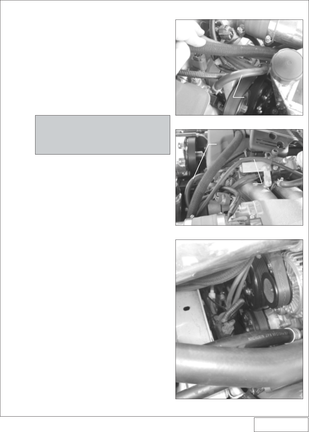
14. HOSE ATTACHMENTS/EXTENSIONS
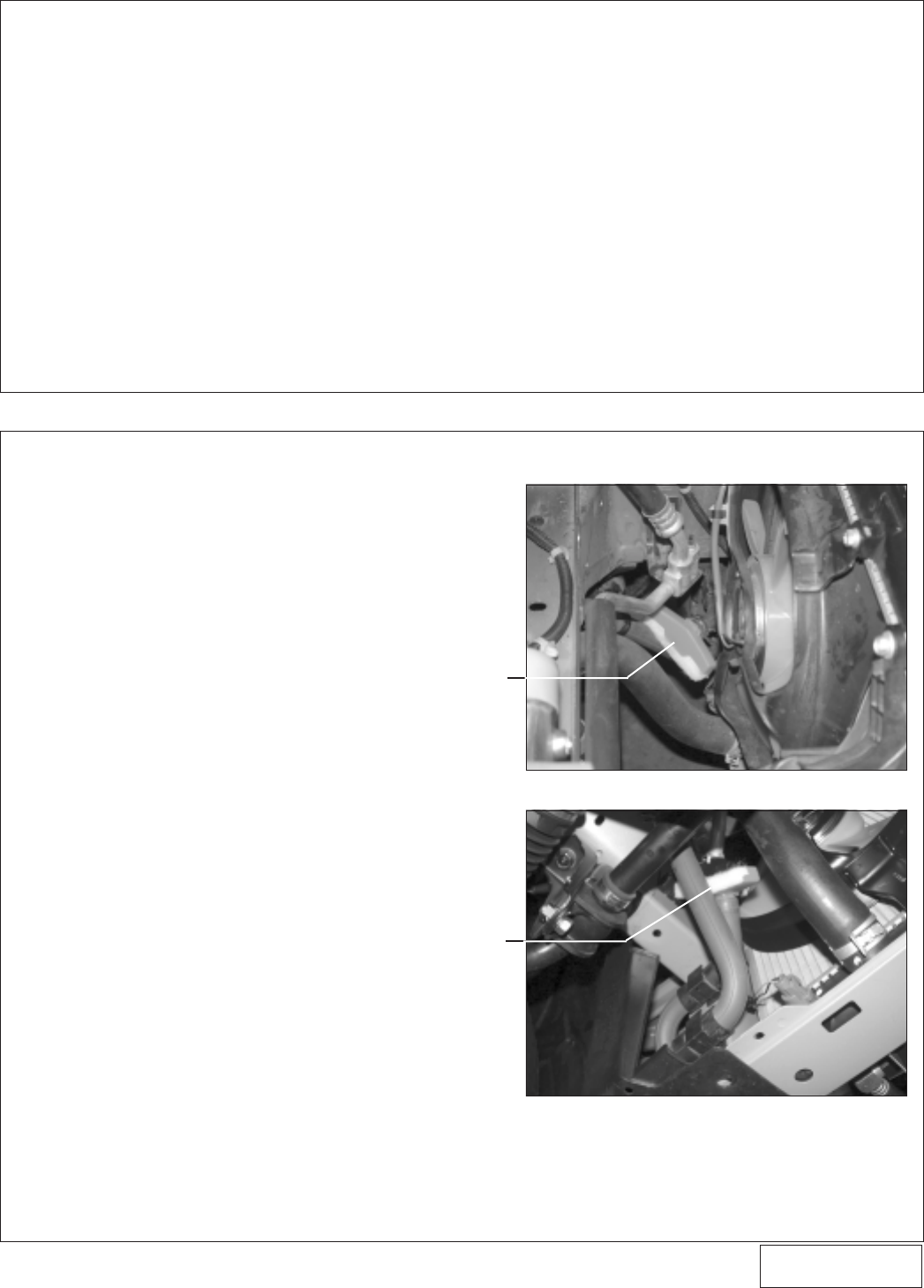
A. Connect the lower end of the supercharger oil
drain hose to the previously installed fitting in the
drain pan using the supplied 90° x 1/2" swivel
hose end. Hose routing must be downhill with
smooth bends and must not have kinks, sharp
bends or uphill sections. Trim hose length if
necessary. Secure the drain hose to the oil pan
fitting with a #8 clamp.
B. Connect the supercharger feed line to the previ-
ously installed flare fitting near the oil pressure
sending unit. Make a gentle forward loop around
and beneath the front crossmember. Secure the
hose with the tie wraps provided, routing it away
from chaffing and/or sharp objects.
C. Attach the supplied piece of 1/4" x 16" long hose
to the cylinder head coolant port that was previ-
ously connected to the factory vacuum/coolant
tubing junction removed in step 1. Attach the
remaining end of the hose to the corresponding
port on the throttle body. Secure both ends with
the previously removed factory clamps. (See
Fig. 14-a, 14-b
.)
D. Install the length of 1/2" x 36" hose to the valve
cover vent barb. Connect the opposite end to the
1/2" brass barb located on the supercharger inlet
elbow. Trim the length if necessary.
E. Attach the length of supplied 1/4" vacuum
hose to the fitting on the cover of the Vortech
compressor bypass valve. Route the hose
over near the fuel rail. Install the supplied 5/32"
-1/4" hose reducer into the end of the 1/4"
hose. Splice one of the supplied 5/32" brass
TEEs into the fuel pressure regulator/FMU
signal hose. Attach the compressor bypass
vacuum hose to the remaining leg of the 5/32
TEE using a short piece of 5/32” vacuum hose.
(See
Fig. 14-b
.)
F. Reconnect the two factory vacuum hoses that
were removed in Step 1. Use the supplied
lengths of 5/32" tubing for extensions if re-
quired.
G. Re-attach the pressure solenoid (that was
removed in Step 1) to the harness and vacuum
hoses. Use a tie wrap to secure the unit down
toward the crossmember and away from the
crank pulley. (See
Fig. 14-c.
)
NOTE: Use only clean engine oil on the pipe
threads. Teflon tape or pipe sealant is not
recommended as it might loosen and cause
blockage of the small oil feed orifice result-
ing in possible supercharger failure.
Fig. 14-a
Fig. 14-b
Fig. 14-c
SUPPLIED 1/4” HOSE x 16”
SUPPLIED 1/4”
HOSE x 16”
COMPRESSOR BYPASS
VACUUM HOSE
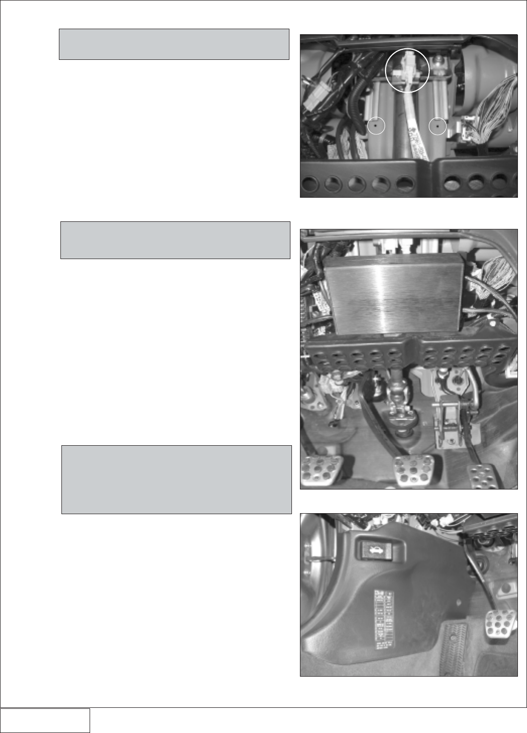
P/N: 4HS020-010
©2004 Vortech Engineering, LLC
All Rights Reserved, Intl. Copr. Secured
27JUL04 v2.0 S2000 (4HSv2.0)
15. ELECTRONIC CONTROL BOX INSTALLATION
A. Unclip the yellow wiring harness near the steer-
ing shaft above the accelerator / brake pedals
located underneath the dash on the interior of the
vehicle. (See
Fig. 15-a.
)
B. Referring to
Fig. 15-a,
mark the mounting hole
locations, spacing should be 3 7/8". Temporarily
attach the brackets to the timing controller and
check for proper spacing.
C. Drill the holes using the self tapping screws and
secure the brackets to the vehicle.
D. Following the diagram (See
Fig.15-e
) attach the
MAP controller to the bottom of the timing con-
troller using the supplied hook and loop fastener.
E. Mount the timing controller to the vehicle using
the supplied 8-32 hardware. Point the vacuum
line toward the drivers side and the wires toward
the passenger side. (See
Fig. 15-b
.)
F. Route the wires of the timing controller toward
the driver’s side.
G. Remove the drivers side kick panel and locate
the vehicles computer. Disconnect the three
electrical connectors to it. (See
Figs. 15-c, 15-d
.)
H. Tap the red wires from the timing controller and
the MAP controller into the yellow/black wire (1
IGP1) on the 25P connector. (See
Fig. 15-f
.)
I. Tap the black wires from the timing controller and
MAP controller into the black wire (2 PG1) on the
25P connector.
J. Cut the green/red wire (17 MAP) on the 31P
connector and install one male and one female
slide connector onto each end.
K. Connect the blue wire from the MAP controller to
the green/red wire leading to the engine com-
partment.
L. Connect the white wire from the MAP controller
to the green/red wire leading to the vehicle’s
computer.
M. Cut the blue wire (8 CKPP) on the 31P connector
and install one male and one female slide con-
nector onto each end.
N. Connect the blue wire from the timing controller
to the blue wire leading to the engine compart-
ment.
NOTE: The MAP controller is offset to one side.
Make sure the wires route toward the
driver’s side door.
Fig. 15-b
Fig. 15-a
32
NOTE: Each of the vehicles wires that are cut should
have a male and female slide connector in-
stalled on each end so that the timing box
or the MAP controller may be unplugged at
any time and the vehicle can run in a stock
configuration.
Fig. 15-c
NOTE: 2004 models do not require the installation
of a map controller.
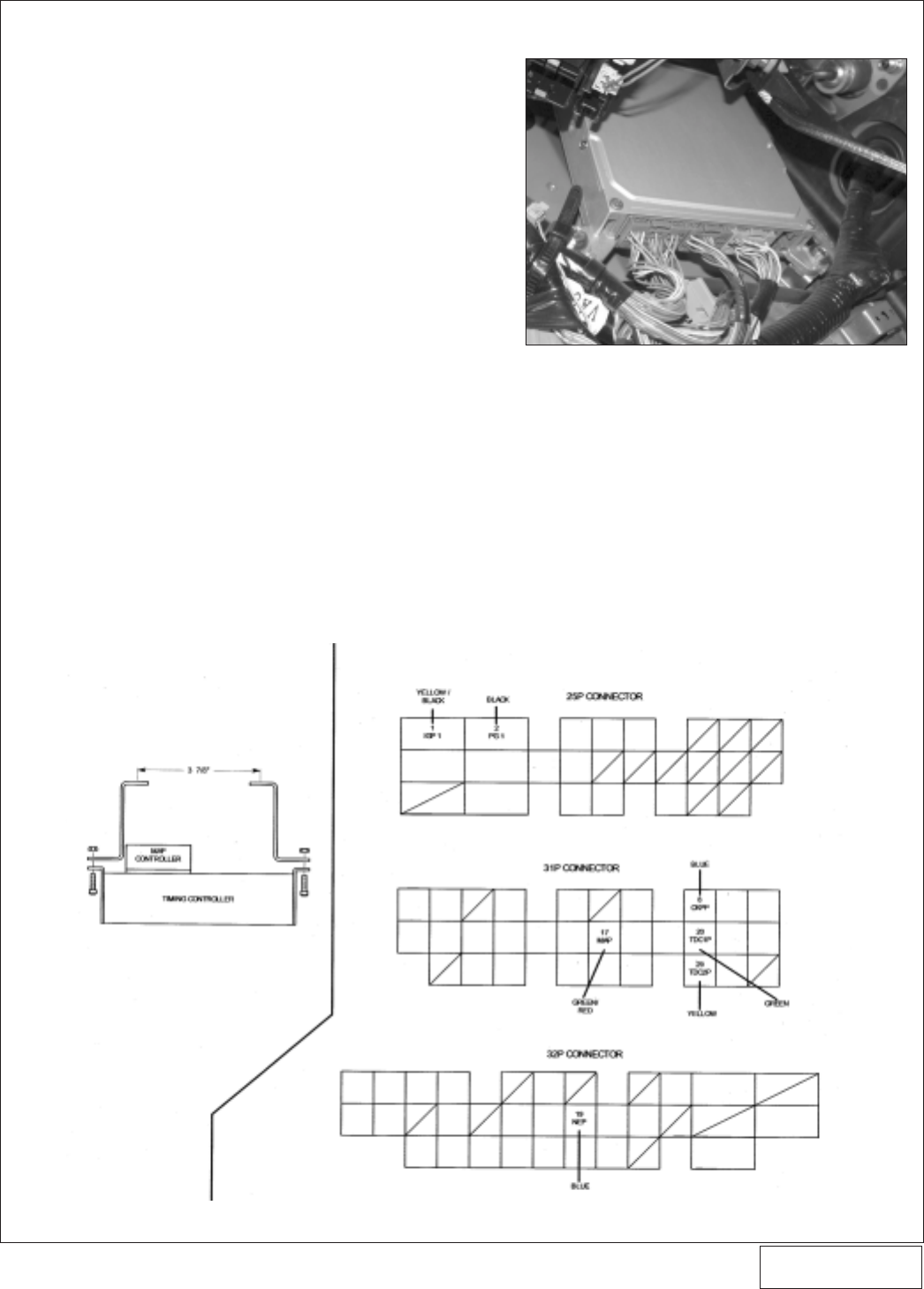
P/N: 4HS020-010
©2004 Vortech Engineering, LLC
All Rights Reserved, Intl. Copr. Secured
27JUL04 v2.0 S2000 (4HSv2.0)
33
O. Connect the blue/red wire from the timing
controller to the blue wire leading to the
vehicle’s computer.
P. Cut the green wire (20 TDC1P) on the 31P
connector and install one male and one
female slide connector onto each end.
Q. Connect the green wire from the timing
controller to the green wire leading to the
engine compartment.
R. Connect the green/red wire from the timing
controller to the green wire leading to the
vehicle’s computer.
S. Cut the yellow wire (20 TDC2P) on the 31P
connector and install one male and one
female slide connector onto each end.
T. Connect the yellow wire from the timing
controller to the green wire leading to the
engine compartment.
U. Connect the yellow/green wire from the
timing controller to the yellow wire leading
to the vehicle’s computer.
V. Route the supplied vacuum line to the rub-
ber grommet that the vehicle’s computer
wires go out of. Punch a small hole in the
rubber grommet and push the vacuum line
out through the hole.
W. Route the vacuum line up to the FMU and
connect into it using the provided brass
TEE.
15. ELECTRONIC CONTROL BOX INSTALLATION, cont’d.
Fig. 15-e
Fig. 15-d
X. Connect the other end of the vacuum line to
the FTC with the provided plastic vacuum
line tap.
Y. (2004 Models) There are four injector plugs
running from the control box. Run one plug
through the firewall to the supplementary
injector installed in the charge cooler. Con-
nect the plug to the injector. (See
Fig. 15-g
.)
Z. (2004 Models) Secure the remaining injec-
tor wires.
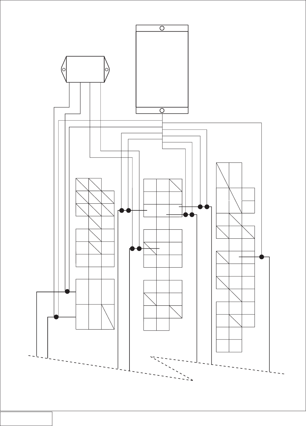
P/N: 4HS020-010
©2004 Vortech Engineering, LLC
All Rights Reserved, Intl. Copr. Secured
27JUL04 v2.0 S2000 (4HSv2.0)
Fig. 15-f / 2001-2003 MODELS
15. ELECTRONIC CONTROL BOX INSTALLATION, cont’d.
34
YELLOW/BLACK
TIMING CONTROLLER
MAP
CONTROLLER
RED
BLACK
BLUE
WHITE
RED
BLACK
BLUE
BLUE/RED
GREEN/RED
GREEN
YELLOW/GREEN
YELLOW
BLUE
32P
31P
25P
YELLOW/
BLACK BLACK
BLUE
WHITE
GREEN/
RED
BLUE
GRN
YEL
RED
BLACK
TO ENGINE COMPARTMENT
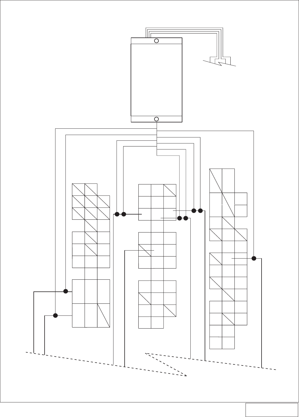
P/N: 4HS020-010
©2004 Vortech Engineering, LLC
All Rights Reserved, Intl. Copr. Secured
27JUL04 v2.0 S2000 (4HSv2.0)
35
Fig. 15-g / 2004 MODELS
YELLOW/BLACK
TIMING CONTROLLER
RED
BLACK
BLUE
BLUE/RED
GREEN/RED
GREEN
YELLOW/GREEN
YELLOW
BLUE
32P
31P
25P
YELLOW/
BLACK BLACK
GREEN/
RED
BLUE
GRN
YEL
RED
BLACK
TO ENGINE COMPARTMENT
GREEN
YELLOW
FUEL INJECTOR PLUGS
15. ELECTRONIC CONTROL BOX INSTALLATION, cont’d.
(2004 Models)

4HS020-010 v2.0 07/27/04
®
ENGINEERING, LLC
1650 PACIFIC AVENUE • CHANNEL ISLANDS, CA 93033-9901 • (805) 247-0226
FAX (805) 247-0669 • www.vortechsuperchargers.com • M-F 8:00 AM - 4:30 PM PST
A. Reconnect the battery.
B. If your vehicle has gone over 20,000 miles since
its last spark plug change, you will need to
change the spark plugs now before test driving
the vehicle.
C. Check all fittings, nuts, bolts and clamps for
tightness. Pay particular attention to oil and fuel
lines around moving parts, sharp edges and
exhaust system parts. Make sure all wires and
lines are properly secured with clamps or tie
wraps.
D. Check all fluid levels, making sure that your
tank(s) is/are filled with 91 octane or higher fuel
before commencing test drive. Turn the ingnition
on to cycle the fuel pump a few times. Check all
fuel fittings for leakage.
E. Start engine and allow to idle a few minutes, then
shut off.
F. Recheck to be sure that no hoses, wires, etc. are
near exhaust headers or moving parts and for
signs of any fluid leakage.
G. PLEASE TAKE SPECIAL NOTE: Operating the
vehicle without ALL the subassemblies com-
pletely and properly installed may cause FAIL-
URE OF MAJOR COMPONENTS.
H. Test drive the vehicle.
I. The supercharger belt stretches initially and will
require adjustment in 250 to 400 miles.
J. Periodically, verify that the supercharger pulley
bolt is tight. Also verify that the belt is not slipping
under boost. (Belt slippage is usually accompa-
nied by a squealing noise at high RPM and a
leveling off or fluctuating boost pressure. If belt
slippage occurs, tighten tensioner.)
K. Read the STREET SUPERCHARGER SYSTEM
OWNER'S MANUAL AND RETURN THE WAR-
RANTY REGISTRATION FORM within thirty
(30) days of purchasing your supercharger sys-
tem to qualify.
16. FINAL CHECK
Fig. 16-a
36
