Voxx Electronics DEI3807 915Mhz spread spectrum 25 channels HHU User Manual 3807A
DEI Headquarters, Inc. 915Mhz spread spectrum 25 channels HHU 3807A
UserManual.wiki
>
Voxx Electronics
>
DEI3807 User Manual
>
user manual 3807A
Contents
1.
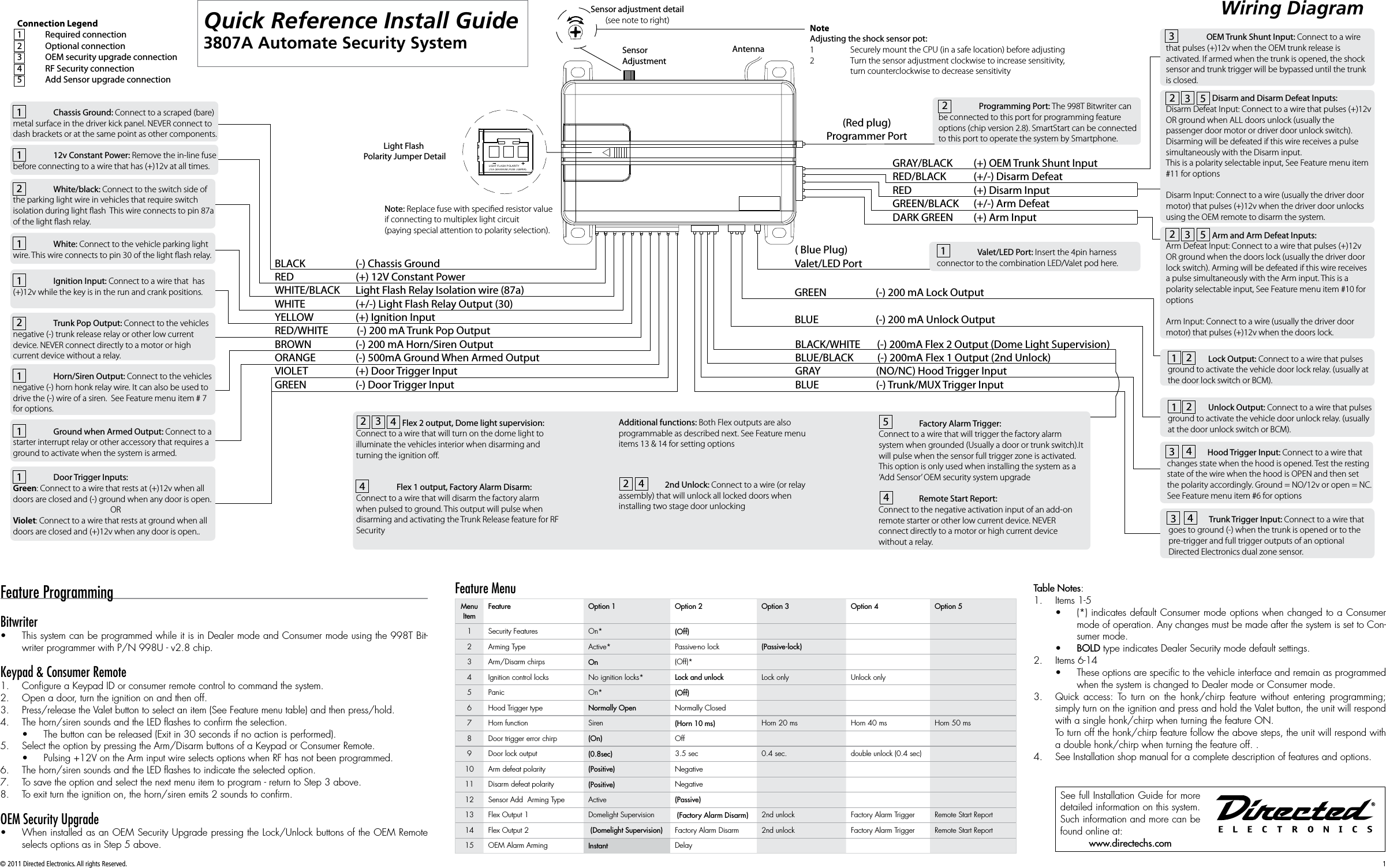
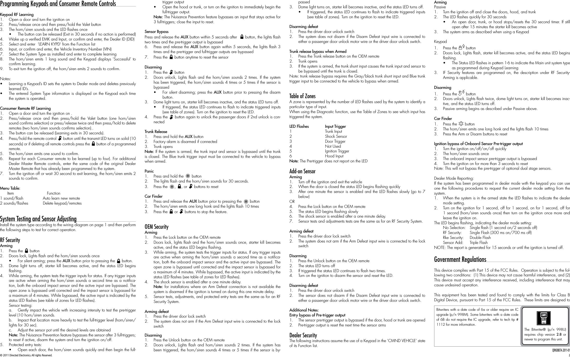
user manual 3807A
2.
user manual 3808A
user manual 3807A
Navigation menu
Upload a User Manual
Namespaces
Wiki Guide
HTML
PDF
Info
Views
User Manual
Discussion / Help
Navigation