Voxx Electronics DEI3807 915Mhz spread spectrum 25 channels HHU User Manual 3807A
DEI Headquarters, Inc. 915Mhz spread spectrum 25 channels HHU 3807A
Contents
- 1. user manual 3807A
- 2. user manual 3808A
user manual 3807A
© 2011 Directed Electronics. All rights Reserved. 1
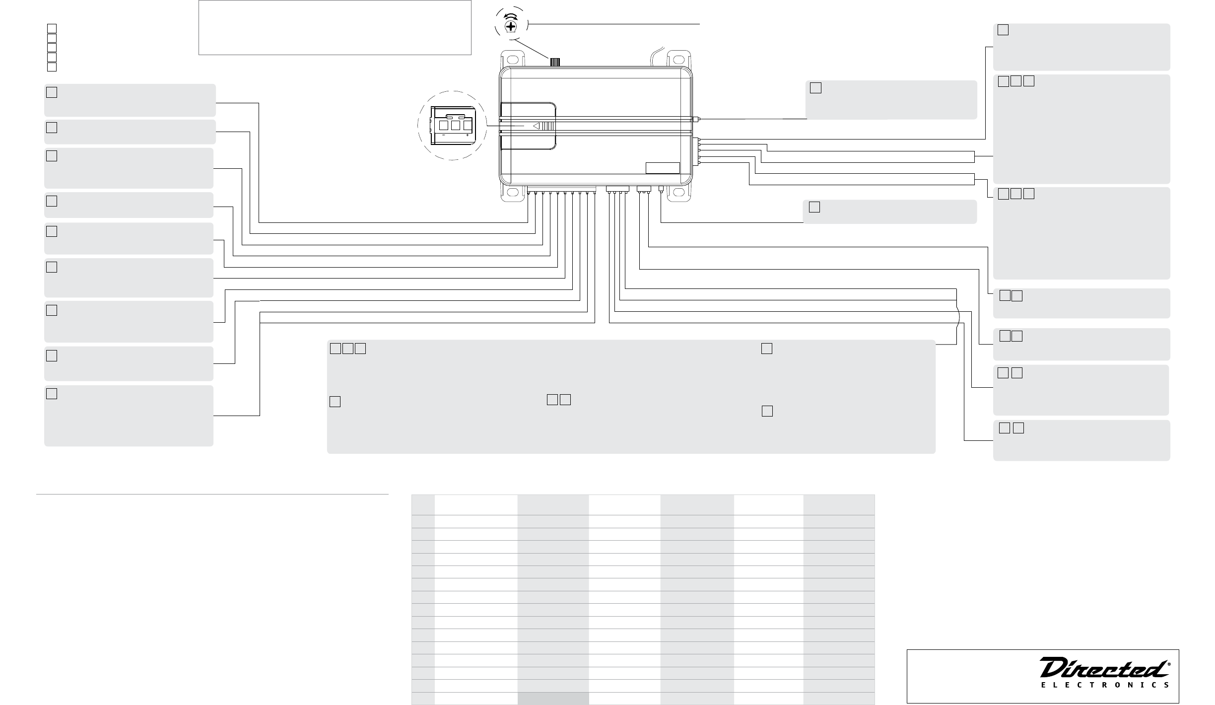
Quick Reference Install Guide
3807A Automate Security System
LIGHT FLASH P OLARITY
(10A (MAXIMUM) FUSE JUMPER)
BLACK (-) Chassis Ground
RED (+) 12V Constant Power
WHITE/BLACK Light Flash Relay Isolation wire (87a)
WHITE (+/-) Light Flash Relay Output (30)
YELLOW (+) Ignition Input
RED/WHITE (-) 200 mA Trunk Pop Output
BROWN (-) 200 mA Horn/Siren Output
ORANGE (-) 500mA Ground When Armed Output
VIOLET (+) Door Trigger Input
GREEN (-) Door Trigger Input
(Red plug)
Programmer Port
BLACK/WHITE (-) 200mA Flex 2 Output (Dome Light Supervision)
BLUE/BLACK (-) 200mA Flex 1 Output (2nd Unlock)
GRAY (NO/NC) Hood Trigger Input
BLUE (-) Trunk/MUX Trigger Input
GREEN (-) 200 mA Lock Output
BLUE (-) 200 mA Unlock Output
( Blue Plug)
Valet/LED Port
Sensor
Adjustment
Antenna
Light Flash
Polarity Jumper Detail GRAY/BLACK (+) OEM Trunk Shunt Input
RED/BLACK (+/-) Disarm Defeat
RED (+) Disarm Input
GREEN/BLACK (+/-) Arm Defeat
DARK GREEN (+) Arm Input
Sensor adjustment detail
(see note to right) Note
Adjusting the shock sensor pot:
1 Securely mount the CPU (in a safe location) before adjusting
2 Turn the sensor adjustment clockwise to increase sensitivity,
turn counterclockwise to decrease sensitivity
Connection Legend
1 Required connection
2 Optional connection
3 OEM security upgrade connection
4 RF Security connection
5 Add Sensor upgrade connection
Note: Replace fuse with specied resistor value
if connecting to multiplex light circuit
(paying special attention to polarity selection).
1
1
2
2
2
3
4
3
3
3
4
5
23
4
5
5
35
Chassis Ground: Connect to a scraped (bare)
metal surface in the driver kick panel. NEVER connect to
dash brackets or at the same point as other components.
1
12v Constant Power: Remove the in-line fuse
before connecting to a wire that has (+)12v at all times.
White/black: Connect to the switch side of
the parking light wire in vehicles that require switch
isolation during light ash This wire connects to pin 87a
of the light ash relay.
1
White: Connect to the vehicle parking light
wire. This wire connects to pin 30 of the light ash relay.
Trunk Pop Output: Connect to the vehicles
negative (-) trunk release relay or other low current
device. NEVER connect directly to a motor or high
current device without a relay.
1
Ignition Input: Connect to a wire that has
(+)12v while the key is in the run and crank positions.
1
Horn/Siren Output: Connect to the vehicles
negative (-) horn honk relay wire. It can also be used to
drive the (-) wire of a siren. See Feature menu item # 7
for options.
1
Ground when Armed Output: Connect to a
starter interrupt relay or other accessory that requires a
ground to activate when the system is armed.
1
Door Trigger Inputs:
Green: Connect to a wire that rests at (+)12v when all
doors are closed and (-) ground when any door is open.
OR
Violet: Connect to a wire that rests at ground when all
doors are closed and (+)12v when any door is open..
2
Programming Port: The 998T Bitwriter can
be connected to this port for programming feature
options (chip version 2.8). SmartStart can be connected
to this port to operate the system by Smartphone.
OEM Trunk Shunt Input: Connect to a wire
that pulses (+)12v when the OEM trunk release is
activated. If armed when the trunk is opened, the shock
sensor and trunk trigger will be bypassed until the trunk
is closed.
2
Disarm and Disarm Defeat Inputs:
Disarm Defeat Input: Connect to a wire that pulses (+)12v
OR ground when ALL doors unlock (usually the
passenger door motor or driver door unlock switch).
Disarming will be defeated if this wire receives a pulse
simultaneously with the Disarm input.
This is a polarity selectable input, See Feature menu item
#11 for options
Disarm Input: Connect to a wire (usually the driver door
motor) that pulses (+)12v when the driver door unlocks
using the OEM remote to disarm the system.
2
Arm and Arm Defeat Inputs:
Arm Defeat Input: Connect to a wire that pulses (+)12v
OR ground when the doors lock (usually the driver door
lock switch). Arming will be defeated if this wire receives
a pulse simultaneously with the Arm input. This is a
polarity selectable input, See Feature menu item #10 for
options
Arm Input: Connect to a wire (usually the driver door
motor) that pulses (+)12v when the doors lock.
1
Valet/LED Port: Insert the 4pin harness
connector to the combination LED/Valet pod here.
1
Lock Output: Connect to a wire that pulses
ground to activate the vehicle door lock relay. (usually at
the door lock switch or BCM).
1
Unlock Output: Connect to a wire that pulses
ground to activate the vehicle door unlock relay. (usually
at the door unlock switch or BCM).
Hood Trigger Input: Connect to a wire that
changes state when the hood is opened. Test the resting
state of the wire when the hood is OPEN and then set
the polarity accordingly. Ground = NO/12v or open = NC.
See Feature menu item #6 for options
34
Trunk Trigger Input: Connect to a wire that
goes to ground (-) when the trunk is opened or to the
pre-trigger and full trigger outputs of an optional
Directed Electronics dual zone sensor.
4
Flex 2 output, Dome light supervision:
Connect to a wire that will turn on the dome light to
illuminate the vehicles interior when disarming and
turning the ignition o.
4
Flex 1 output, Factory Alarm Disarm:
Connect to a wire that will disarm the factory alarm
when pulsed to ground. This output will pulse when
disarming and activating the Trunk Release feature for RF
Security
24
2nd Unlock: Connect to a wire (or relay
assembly) that will unlock all locked doors when
installing two stage door unlocking
Factory Alarm Trigger:
Connect to a wire that will trigger the factory alarm
system when grounded (Usually a door or trunk switch).It
will pulse when the sensor full trigger zone is activated.
This option is only used when installing the system as a
‘Add Sensor’ OEM security system upgrade
Remote Start Report:
Connect to the negative activation input of an add-on
remote starter or other low current device. NEVER
connect directly to a motor or high current device
without a relay.
Additional functions: Both Flex outputs are also
programmable as described next. See Feature menu
items 13 & 14 for setting options
2
2
Wiring Diagram
Feature Menu
Menu
Item
Feature Option 1 Option 2 Option 3 Option 4 Option 5
1 Security Features On* (Off)
2 Arming Type Active* Passive-no lock (Passive-lock)
3 Arm/Disarm chirps On (Off)*
4 Ignition control locks No ignition locks* Lock and unlock Lock only Unlock only
5 Panic On* (Off)
6 Hood Trigger type Normally Open Normally Closed
7 Horn function Siren (Horn 10 ms) Horn 20 ms Horn 40 ms Horn 50 ms
8 Door trigger error chirp (On) Off
9 Door lock output (0.8sec) 3.5 sec 0.4 sec. double unlock (0.4 sec)
10 Arm defeat polarity (Positive) Negative
11 Disarm defeat polarity (Positive) Negative
12 Sensor Add Arming Type Active (Passive)
13 Flex Output 1 Domelight Supervision (Factory Alarm Disarm) 2nd unlock Factory Alarm Trigger Remote Start Report
14 Flex Output 2 (Domelight Supervision) Factory Alarm Disarm 2nd unlock Factory Alarm Trigger Remote Start Report
15 OEM Alarm Arming Instant Delay
Feature Programming
Bitwriter
• This system can be programmed while it is in Dealer mode and Consumer mode using the 998T Bit-
writer programmer with P/N 998U - v2.8 chip.
Keypad & Consumer Remote
1. Configure a Keypad ID or consumer remote control to command the system.
2. Open a door, turn the ignition on and then off.
3. Press/release the Valet button to select an item (See Feature menu table) and then press/hold.
4. The horn/siren sounds and the LED flashes to confirm the selection.
• The button can be released (Exit in 30 seconds if no action is performed).
5. Select the option by pressing the Arm/Disarm buttons of a Keypad or Consumer Remote.
• Pulsing +12V on the Arm input wire selects options when RF has not been programmed.
6. The horn/siren sounds and the LED flashes to indicate the selected option.
7. To save the option and select the next menu item to program - return to Step 3 above.
8. To exit turn the ignition on, the horn/siren emits 2 sounds to confirm.
OEM Security Upgrade
• When installed as an OEM Security Upgrade pressing the Lock/Unlock buttons of the OEM Remote
selects options as in Step 5 above.
Table Notes:
1. Items 1-5
• (*) indicates default Consumer mode options when changed to a Consumer
mode of operation. Any changes must be made after the system is set to Con-
sumer mode.
• BOLD type indicates Dealer Security mode default settings.
2. Items 6-14
• These options are specific to the vehicle interface and remain as programmed
when the system is changed to Dealer mode or Consumer mode.
3. Quick access: To turn on the honk/chirp feature without entering programming;
simply turn on the ignition and press and hold the Valet button, the unit will respond
with a single honk/chirp when turning the feature ON.
To turn off the honk/chirp feature follow the above steps, the unit will respond with
a double honk/chirp when turning the feature off. .
4. See Installation shop manual for a complete description of features and options.
See full Installation Guide for more
detailed information on this system.
Such information and more can be
found online at:
www.directechs.com
Logo, Directed Electronics w-driven.eps
Logo, Directed with designed in USA.eps
Logo, Directed with Distributed By.eps
Directed Logo Usage

© 2011 Directed Electronics. All rights Reserved. 2
QRN3807A 2011-01
Programming Keypads and Consumer Remote Controls
Keypad RF Learning
1. Open a door and turn the ignition on
2. Press/release once and then press/hold the Valet button
3. The horn/siren sounds and the LED flashes once
• The button can be released (Exit in 30 seconds if no action is performed)
4. Wake up a verified EMK and Input, or confirm and enter, the Dealer ID (DID)
5. Select and enter ‘LEARN KYPD’ from the Function list
6. Input, or confirm and enter, the Vehicle Inventory Number (VIN)
7. Select the System Type as installed and enter to complete learning
8. The horn/siren emits 1 long sound and the Keypad displays ‘Successful’ to
confirm learning.
9. To exit turn the ignition off, the horn/siren emits 2 sounds to confirm.
Notes:
• Learning a Keypad’s ID sets the system to Dealer mode and deletes previously
learned ID’s.
• The entered System Type information is displayed on the Keypad each time
the system is operated.
Consumer Remote RF Learning
1. Open a door and turn the ignition on .
2. Press/release once and then press/hold the Valet button (one horn/siren
sound confirms selection) or press/release twice and then press/hold to delete
remotes (two horn/siren sounds confirms selection)..
3. The button can be released (Learning exits in 30 seconds).
4. Press/hold the remote control
A U X
button until the transmit LED turns on solid (10
seconds) or if deleting all remote controls press the
A U X
button of a programmed
remote.
5. The horn/siren emits one sound to confirm.
6. Repeat for each Consumer remote to be learned (up to four). For additional
Dealer Master Remote controls, enter the same code of the original Dealer
Master Remote that has already been programmed to the system.
7. Turn the ignition off or wait 30 second to exit learning, the horn/siren emits 2
sounds to confirm.
Menu Table:
Item Function
1 sound/flash Auto learn new remote
2 sounds/flashes Delete keypad/remotes
System Testing and Sensor Adjusting
Install the system type according to the wiring diagram on page 1 and then perform
the following steps to test for correct operation.
RF Security
Arming
1. Press the
A U X
button
2. Doors lock, Lights flash and the horn/siren sounds once
• For silent arming; press the AUX button prior to pressing the
A U X
button.
3. Dome light turns off, starter kill becomes active, and the status LED begins
flashing.
4. While arming, the system tests the trigger inputs for status. If any trigger inputs
are active when arming the horn/siren sounds a second time as a notifica-
tion, both the onboard impact sensor and the active input are bypassed. The
open zone is bypassed until corrected and the impact sensor is bypassed for
a maximum of 4 minutes. While bypassed, the active input is indicated by the
status LED flashes (see table of zones for LED flashes).
Sensor testing:
a. Gently impact the vehicle with increasing intensity to test the pre-trigger
level (10 horn/siren sounds.
b. Impact that location more heavily to test the full-trigger level (horn/siren/
lights for 30 sec).
c. Adjust the sensor pot until the desired levels are obtained
Note: The Nuisance Prevention feature bypasses the sensor after 3 full-triggers;
to reset if active, disarm the system and turn the ignition on/off.
5. Protected entry tests:
• Open each door, the horn/siren sounds quickly and then begin the full-
trigger output
• Open the hood or trunk, or turn on the ignition to immediately begin the
full-trigger output.
Note: The Nuisance Prevention feature bypasses an input that stays active for
3 full-triggers; close the input to reset.
Sensor Bypass
Press and release the AUX button within 5 seconds after
A U X
button, the lights flash
two times and the pre-trigger output is bypassed
6. Press and release the AUX button again within 5 seconds, the lights flash 3
times and the pre-trigger and full-trigger outputs are bypassed
7. Press the
A U X
button anytime to reset the sensor
Disarming
1. Press the
A U X
button
2. Doors unlock, Lights flash and the horn/siren sounds 2 times. If the system
has been triggered, the horn/siren sounds 4 times or 5 times if the sensor is
bypassed
• For silent disarming; press the AUX button prior to pressing the disarm
button.
3. Dome light turns on, starter kill becomes inactive, and the status LED turns off.
• If triggered, the status LED continues to flash to indicate triggered inputs
(see table of zones). Turn on the ignition to reset the LED.
4. Press the
A U X
button again to unlock the passenger doors if 2nd unlock is con-
nected
Trunk Release
1. Press and hold the AUX button
2. Factory alarm is disarmed if connected
3. Trunk opens
Note: If the system is armed, the trunk input and sensor is bypassed until the trunk
is closed. The Blue trunk trigger input must be connected to the vehicle to bypass
when armed.
Panic
1. Press and hold the
AUX
AUX
button
2. The lights flash and the horn/siren sounds for 30 seconds.
3. Press the
AUX
AUX
,
A U X
, or
A U X
buttons to reset
Car Finder
1. Press and release the AUX button prior to pressing the
AUX
AUX
button
2. The horn/siren emits one long honk and the lights flash 10 times
3. Press the
A U X
or
A U X
buttons to stop the feature.
OEM Security
Arming
1. Press the Lock button on the OEM remote
2. Doors lock, lights flash and the horn/siren sounds once, starter kill becomes
active, and the status LED begins flashing.
3. While arming, the system tests the trigger inputs for status. If any trigger inputs
are active when arming the horn/siren sounds a second time as a notifica-
tion, both the onboard impact sensor and the active input are bypassed. The
open zone is bypassed until corrected and the impact sensor is bypassed for
a maximum of 4 minutes. While bypassed, the active input is indicated by the
status LED flashes (see table of zones for LED flashes).
4. The shock sensor is enabled after a one minute delay.
Note: for installations where an Arm Defeat connection is not available the
system is disarmed if the ignition is turned on during this one minute delay.
5. Sensor tests, adjustments, and protected entry tests are the same as for an RF
Security System.
Arming defeat
1. Press the driver door lock switch
2. The system does not arm if the Arm Defeat input wire is connected to the lock
switch
Disarming
1. Press the Unlock button on the OEM remote
2. Doors unlock, Lights flash and horn/siren sounds 2 times. If the system has
been triggered, the horn/siren sounds 4 times or 5 times if the sensor is by-
passed
3. Dome light turns on, starter kill becomes inactive, and the status LED turns off.
• If triggered, the status LED continues to flash to indicate triggered inputs
(see table of zones). Turn on the ignition to reset the LED.
Disarming defeat
1. Press the driver door unlock switch
2. The system does not disarm if the Disarm Defeat input wire is connected to
either a passenger door unlock motor wire or the driver door unlock switch.
Trunk release bypass when Armed
1. Press the Trunk release button on the OEM remote
2. Trunk opens
3. If the system is armed, the trunk shunt input causes the trunk input and sensor to
be bypassed until the trunk is closed.
Note: trunk release bypass requires the Gray/black trunk shunt input and Blue trunk
trigger input to be connected to the vehicle to bypass when armed.
Table of Zones
A zone is represented by the number of LED flashes used by the system to identify a
particular type of input.
When using the Diagnostic function, use the Table of Zones to see which input has
triggered the system.
LED Flashes Input Trigger
1 Trunk Input
2 Shock Sensor
3 Door Trigger
4 Not Used
5 Ignition Trigger
6 Hood Input
Note: The Pre-trigger does not report on the LED
Add-on Sensor
Arming
1. Turn off the ignition and exit the vehicle
2. When the door is closed the status LED begins flashing quickly
3. After one minute the sensor is enabled and the LED flashes slowly (go to 7
below)
OR
4. Press the Lock button on the OEM remote
5. The status LED begins flashing slowly
6. The shock sensor is enabled after a one minute delay.
7. Sensor tests and adjustments tests are the same as for an RF Security System.
Arming defeat
1. Press the driver door lock switch
2. The system does not arm if the Arm Defeat input wire is connected to the lock
switch
Disarming
1. Press the Unlock button on the OEM remote
2. The status LED turns off
3. If triggered the status LED continues to flash two times.
4. Turn on the ignition to disarm the sensor and reset the LED.
Disarming defeat
1. Press the driver door unlock switch
2. The sensor does not disarm if the Disarm Defeat input wire is connected to
either a passenger door unlock motor wire or the driver door unlock switch.
Additional Notes:
Entry bypass of Pre-trigger output
1. The sensor pre-trigger output is bypassed if the door, hood or trunk are opened
2. Pre-trigger output is reset the next time the sensor arms
Dealer Security
The following instructions assume the use of a Keypad in the ‘CMND VEHICLE’ state
of its Function list.
Arming
Passive
1. Turn the ignition off and close the doors, hood, and trunk
2. The LED flashes quickly for 30 seconds
• An open door, trunk, or hood stops/resets the 30 second timer. If still
open after 15 minutes the starter kill becomes active
3. The system arms as described when using a Keypad
Keypad
1. Press the button
2. Doors lock, Lights flash, starter kill becomes active, and the status LED begins
flashing.
• The Status LED flashes in pattern 1-6 to indicate the Main unit system type
as programmed during Keypad Learning
3. IF Security features are programmed on, the description under RF Security-
Arming is applicable.
Disarming
1. Press the button
2. Doors unlock, Lights flash twice, dome light turns on, starter kill becomes inac-
tive, and the status LED turns off.
3. Passive arming begins as described under Passive above.
Car Finder
1. Press the button
2. The horn/siren emits one long honk and the lights flash 10 times
3. Press the Arm or Disarm buttons to reset
Ignition bypass of Onboard Sensor Pre-trigger output
1. Turn the ignition on/off/on/off quickly
2. The horn/siren sounds once
3. The onboard impact sensor pre-trigger output is bypassed
4. Turn the ignition on for more than 3 seconds to reset
Note: This will not bypass the pre-trigger of optional dual stage sensors.
Dealer Mode Reporting:
If the system has been programmed in dealer mode with the keypad you can use
one the following procedures to request the current dealer mode setting from the
system.
1. When the system is in the armed state the LED flashes to indicate the dealer
mode setting.
2. Turn on the ignition for 1 second, off for 1 second, on for 1 second, off for
1 second (horn/siren sounds once) then turn on the ignition once more and
leave the ignition on.
The LED begins flashing, indicating the dealer mode setting:
No Selection: Single flash (1 second on/2 seconds off)
RF Security: Single Flash (300 ms on/700 ms off)
Rke Security: Double Flash
Sensor Add: Triple Flash
NOTE: The report is generated for 15 seconds or until the ignition is turned off.
Government Regulations
This device complies with Part 15 of the FCC Rules. Operation is subject to the fol-
lowing two conditions: (1) This device may not cause harmful interference, and (2)
This device must accept any interference received, including interference that may
cause undesired operation.
This equipment has been tested and found to comply with the limits for Class B
Digital Device, pursuant to Part 15 of the FCC Rules. These limits are designed to
Bitwriters with a date code of 6a or older require an IC
upgrade (p/n 998M). Some bitwriters with a date code
of 6B do not require the IC upgrade, refer to tech tip #
1112 for more information.
The Bitwriter® (p/n 998U)
requires chip version 2.8 or
newer to program this unit.
© 2011 Directed Electronics. All rights Reserved. 3
provide reasonable protection against harmful interference in a residential instal-
lation. This equipment generates and can radiate radio frequency energy and,
if not installed and used in accordance with the instructions, may cause harmful
interference to radio communications. However, there is no guarantee that interfer-
ence will not occur in a particular installation. If this equipment does cause harmful
interference to radio or television reception, which can be determined by turning the
equipment off and on, the user is encouraged to try to correct the interference by one
or more of the following measures.
• Reorient or relocate the receiving antenna
• Increase the separation between the equipment and receiver
• Connect the equipment into an outlet on a circuit different from that to which
the receiver is connected
• Consult the dealer or an experienced radio/TV technician for help
Any changes or modifications not expressly approved by the party responsible for
compliance could void the user’s authority to operate the equipment.
Canada statements:
This device complies with Industry Canada licence-exempt RSS standard(s). Opera-
tion is subject to the following two conditions: (1) this device may not cause interfer-
ence, and (2) this device must accept any interference, including interference that
may cause undesired operation of the device.
Le présent appareil est conforme aux CNR d’Industrie Canada applicables aux
appareils radio exempts de licence. L’exploitation est autorisée aux deux conditions
suivantes : (1) l’appareil ne doit pas produire de brouillage, et (2) l’utilisateur de
l’appareil doit accepter tout brouillage radioélectrique subi, même si le brouillage
est susceptible d’en compromettre le fonctionnement.