Vxi Tv Video Accessories Ct 400 Users Manual
CT-400 to the manual 3211f5c4-8b20-4305-a1ee-8233adcf85fc
2015-02-05
: Vxi Vxi-Tv-Video-Accessories-Ct-400-Users-Manual-459139 vxi-tv-video-accessories-ct-400-users-manual-459139 vxi pdf
Open the PDF directly: View PDF ![]() .
.
Page Count: 57

.
bus
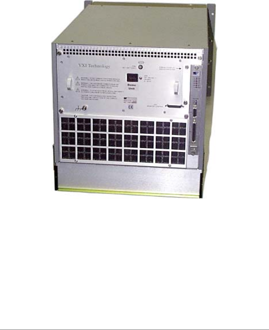
CT-400 CHASSIS
THIRTEEN-SLOT VXIBUS CHASSIS
USER’S MANUAL
P/N: 82-0050-000
Released December 21, 2007
VXI Technology, Inc.
2031 Main Street
Irvine, CA 92614-6509
(949) 955-1894

2

www.vxitech.com
CT-400 Preface 3
TABLE OF CONTENTS
INTRODUCTION
Certification .........................................................................................................................................................5
Warranty ..............................................................................................................................................................5
Limitation of Warranty ........................................................................................................................................5
Restricted Rights Legend .....................................................................................................................................5
DECLARATION OF CONFORMITY ................................................................................................................................6
GENERAL SAFETY INSTRUCTIONS..............................................................................................................................7
Terms and Symbols..............................................................................................................................................7
Warnings..............................................................................................................................................................7
SUPPORT RESOURCES ................................................................................................................................................9
SECTION 1 ...................................................................................................................................................................11
INTRODUCTION ........................................................................................................................................................11
Introduction........................................................................................................................................................11
General Description ...........................................................................................................................................12
Power Supplies...................................................................................................................................................12
Backplane...........................................................................................................................................................12
Cooling...............................................................................................................................................................12
CT-400 Mainframe Features..............................................................................................................................13
Voltage Indicator LEDs .....................................................................................................................................14
Rear Panel Monitor / Control Connector ...........................................................................................................15
CT-400 Specifications .......................................................................................................................................16
SECTION 2 ...................................................................................................................................................................25
INSTALLATION .........................................................................................................................................................25
Introduction........................................................................................................................................................25
Power Requirements ..........................................................................................................................................25
Connecting the Mainframe to Earth Ground......................................................................................................26
Air Flow Requirements......................................................................................................................................26
Installing the Card Shield Option.......................................................................................................................27
Installing Blanking Panels .................................................................................................................................27
BENCH-TOP CT-400 USE .........................................................................................................................................28
Overview............................................................................................................................................................28
RACK MOUNTING THE CT-400 ................................................................................................................................29
Overview............................................................................................................................................................29
Assembly Preparation ........................................................................................................................................29
Mounting the Mainframe ...................................................................................................................................29
Option 100 - Adjustable Rack Mount Flanges with Handles ............................................................................30
Option 101 - VXIplug&play Rack Mount Kit ...................................................................................................32
Option 102 - Rack Mount Slides........................................................................................................................34
ADDITIONAL RACK MOUNT OPTIONS ......................................................................................................................36
Overview............................................................................................................................................................36
Option 103 - Transparent Front Door Installation Procedure ............................................................................38
Option 104 - Hinged Custom Front Panel Installation Procedure .....................................................................40
Option 105/106 - 1U/2U Cable Trays Installation Procedure............................................................................42
INSTALLATION OF VXI MODULES ...........................................................................................................................44
Overview............................................................................................................................................................44
DISCONNECTING THE MAINFRAME ..........................................................................................................................45

VXI Technology, Inc.
4 CT-400 Preface
SECTION 3 ...................................................................................................................................................................47
OPERATION..............................................................................................................................................................47
Introduction........................................................................................................................................................47
Remote Power Control.......................................................................................................................................47
CT-400 Monitor Board ......................................................................................................................................48
CT-400 Monitor Board - Signals .......................................................................................................................49
Connector J210..............................................................................................................................................49
Connector J211..............................................................................................................................................50
SECTION 4 ...................................................................................................................................................................51
SERVICE INFORMATION ...........................................................................................................................................51
Introduction........................................................................................................................................................51
Cleaning the Air Filters......................................................................................................................................52
Cleaning the Power Supply Fan Filter ..........................................................................................................52
Cleaning the Module Fan Filter ....................................................................................................................53
Power Supply Replacement Procedure ..............................................................................................................54
INDEX ..........................................................................................................................................................................57

www.vxitech.com
CT-400 Preface 5
CERTIFICATION
VXI Technology, Inc. (VTI) certifies that this product met its published specifications at the time of shipment from
the factory. VTI further certifies that its calibration measurements are traceable to the United States National
Institute of Standards and Technology (formerly National Bureau of Standards), to the extent allowed by that
organization’s calibration facility, and to the calibration facilities of other International Standards Organization
members.
WARRANTY
The product referred to herein is warranted against defects in material and workmanship for a period of three years
from the receipt date of the product at customer’s facility. The same warranty applies to the power supply for a
period of one year. The sole and exclusive remedy for breach of any warranty concerning these goods shall be
repair or replacement of defective parts, or a refund of the purchase price, to be determined at the option of VTI.
For warranty service or repair, this product must be returned to a VXI Technology authorized service center. The
product shall be shipped prepaid to VTI and VTI shall prepay all returns of the product to the buyer. However, the
buyer shall pay all shipping charges, duties, and taxes for products returned to VTI from another country.
VTI warrants that its software and firmware designated by VTI for use with a product will execute its programming
when properly installed on that product. VTI does not however warrant that the operation of the product, or
software or firmware will be uninterrupted or error free.
LIMITATION OF WARRANTY
The warranty shall not apply to defects resulting from improper or inadequate maintenance by the buyer, buyer-
supplied products or interfacing, unauthorized modification or misuse, operation outside the environmental
specifications for the product, or improper site preparation or maintenance.
VXI Technology, Inc. shall not be liable for injury to property other than the goods themselves. Other than the
limited warranty stated above, VXI Technology, Inc. makes no other warranties, express, or implied, with respect to
the quality of product beyond the description of the goods on the face of the contract. VTI specifically disclaims the
implied warranties of merchantability and fitness for a particular purpose.
RESTRICTED RIGHTS LEGEND
Use, duplication, or disclosure by the Government is subject to restrictions as set forth in subdivision (b)(3)(ii) of
the Rights in Technical Data and Computer Software clause in DFARS 252.227-7013.
VXI Technology, Inc.
2031 Main Street
Irvine, CA 92614-6509 U.S.A.

VXI Technology, Inc.
6 CT-400 Preface
DECLARATION OF CONFORMITY
Declaration of Conformity According to ISO/IEC Guide 22 and EN 45014
MANUFACTURER’S NAME VXI Technology, Inc.
MANUFACTURER’S ADDRESS 2031 Main Street
Irvine, California 92614-6509
PRODUCT NAME Thirteen-Slot VXIbus Chassis
MODEL NUMBER(S) CT-400
PRODUCT OPTIONS All
PRODUCT CONFIGURATIONS All
VXI Technology, Inc. declares that the aforementioned product conforms to the requirements of
the Low Voltage Directive 73/23/EEC and the EMC Directive 89/366/EEC (inclusive 93/68/EEC)
and carries the “CE” mark accordingly. The product has been designed and manufactured
according to the following specifications:
SAFETY EN61010 (2001)
EMC EN61326 (1997 w/A1:98) Class A
CISPR 22 (1997) Class A
VCCI (April 2000) Class A
ICES-003 Class A (ANSI C63.4 1992)
AS/NZS 3548 (w/A1 & A2:97) Class A
FCC Part 15 Subpart B Class A
EN 61010-1:2001
I hereby declare that the aforementioned product has been designed to be in compliance with the relevant sections
of the specifications listed above as well as complying with all essential requirements of the Low Voltage Directive.
December 2007
Steve Mauga, QA Manager
www.vxitech.com
CT-400 Preface 7
GENERAL SAFETY INSTRUCTIONS
Review the following safety precautions to avoid bodily injury and/or damage to the product.
These precautions must be observed during all phases of operation or service of this product.
Failure to comply with these precautions, or with specific warnings elsewhere in this manual,
violates safety standards of design, manufacture, and intended use of the product.
Service should only be performed by qualified personnel.
TERMS AND SYMBOLS
These terms may appear in this manual:
Indicates that a specific WARNING or CAUTION follows.
WARNING Indicates that a procedure or condition may cause bodily injury or death.
CAUTION Indicates that a procedure or condition could possibly cause damage to
equipment or loss of data.
These symbols may appear on the product:
WARNING Indicates that a procedure or condition may cause bodily injury or death.
!
ATTENTION - Important safety instructions
Frame or chassis ground
Alternating Current (ac)
Indicates that the product was manufactured after August 13, 2005. This mark is
placed in accordance with EN 50419, Marking of electrical and electronic
equipment in accordance with Article 11(2) of Directive 2002/96/EC (WEEE).
End-of-life product can be returned to VTI by obtaining an RMA number. Fees
for take-back and recycling will apply if not prohibited by national law.
WARNINGS
Follow these precautions to avoid injury or damage to the product:
Use Proper Power Cord To avoid hazard, only use the power cord specified for this product.
Use Proper Power Source To avoid electrical overload, electric shock, or fire hazard, do not
use a power source that applies other than the specified voltage.

VXI Technology, Inc.
8 CT-400 Introduction
WARNINGS (CONT.)
Use Proper Fuse To avoid fire hazard, only use the type and rating fuse specified for
this product.
Avoid Electric Shock To avoid electric shock or fire hazard, do not operate this product
with the covers removed. Do not connect or disconnect any cable,
probes, test leads, etc. while they are connected to a voltage source.
Remove all power and unplug unit before performing any service.
Service should only be performed by qualified personnel.
Ground the Product This product is grounded through the grounding conductor of the
power cord. To avoid electric shock, the grounding conductor must
be connected to earth ground.
Operating Conditions To avoid injury, electric shock or fire hazard:
- Do not operate in wet or damp conditions.
- Do not operate in an explosive atmosphere.
- Operate or store only in specified temperature range.
- Provide proper clearance for product ventilation to prevent
overheating.
- DO NOT operate if you suspect there is any damage to this
product. Product should be inspected or serviced only by
qualified personnel.
Improper Use The operator of this instrument is advised that if the equipment is
used in a manner not specified in this manual, the protection
provided by the equipment may be impaired.
Conformity is checked by inspection.

www.vxitech.com
CT-400 Preface 9
SUPPORT RESOURCES
Support resources for this product are available on the Internet and at VXI Technology customer
support centers.
VXI Technology
World Headquarters
VXI Technology, Inc.
2031 Main Street
Irvine, CA 92614-6509
Phone: (949) 955-1894
Fax: (949) 955-3041
VXI Technology
Cleveland Instrument Division
5425 Warner Road
Suite 13
Valley View, OH 44125
Phone: (216) 447-8950
Fax: (216) 447-8951
VXI Technology
Lake Stevens Instrument Division
VXI Technology, Inc.
1924 - 203 Bickford
Snohomish, WA 98290
Phone: (425) 212-2285
Fax: (425) 212-2289
Technical Support
Phone: (949) 955-1894
Fax: (949) 955-3041
E-mail: support@vxitech.com
Visit http://www.vxitech.com for worldwide support sites and service plan information.

VXI Technology, Inc.
10 CT-400 Introduction
www.vxitech.com
CT-400 Introduction 11
SECTION 1
INTRODUCTION
INTRODUCTION
This section contains a general description of operating features of the CT-400. A list of
mainframe features follows the description, which is then followed by a brief discussion of the
options available for the CT-400.
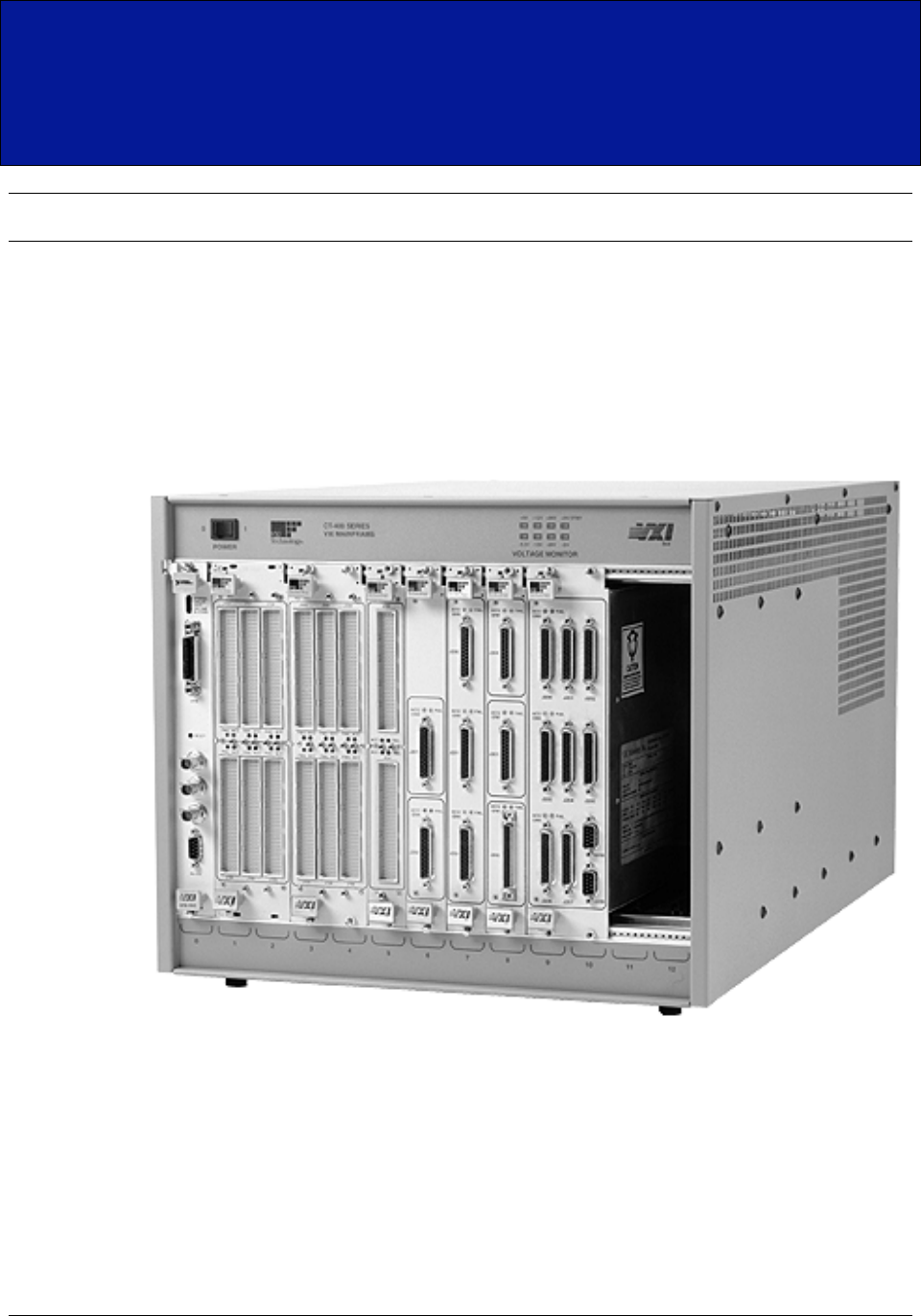
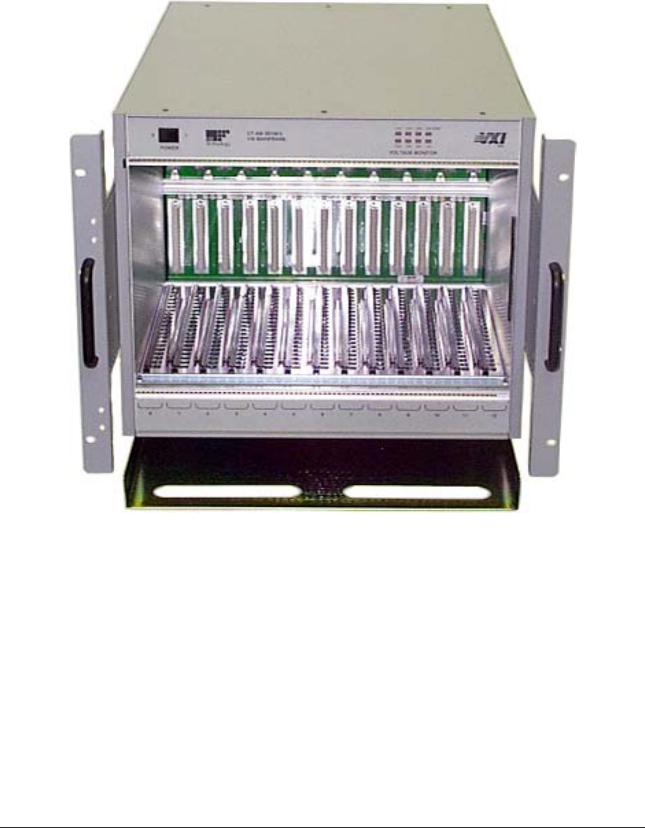
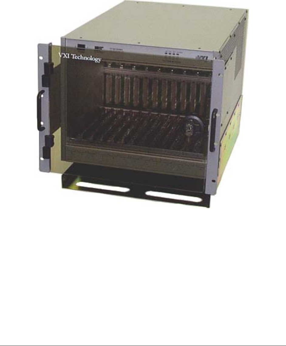
FIGURE 1-1: CT-400 THIRTEEN-SLOT MAINFRAME WITH MODULES

VXI Technology, Inc.
12 CT-400 Introduction
GENERAL DESCRIPTION
The CT-400 mainframe is a C-size, thirteen-slot, VXIbus compatible mainframe that conforms
fully to VXIbus Specification Revision 1.4. The mainframe employs a multi-layer backplane to
ensure premium VXIbus and VMEbus performance and provides all power supplies required by
the VXIbus specification.
The CT-400 mainframe contains thirteen slots in the card cage, twelve of which are available for
use by VXIbus compatible instruments. The thirteenth slot in the card cage (slot 0) is typically
dedicated to the VXIbus Resource Manager.
POWER SUPPLIES
The CT-400 is designed to operate at line frequencies from 47 Hz to 440 Hz and is factory preset
to operate at a nominal line voltage of 115 V ac. The ac input is both auto-voltage and auto-
frequency ranging and may be reconfigured to operate at a nominal 220 V ac by simply changing
the fuse located at the rear of the chassis.
The power supply assembly is completely removable from the rear of the mainframe. The
assembly is short-circuit, over-voltage, reverse-voltage and thermal-shutdown protected. In
addition, all supply lines are monitored and displayed on the front panel to provide user-feedback
of correct operation.
BACKPLANE
The CT-400 has a jumperless auto-configurable backplane with automatic bus grant and IACK
jumpering. There is also a custom power sub-panel to distribute all the supply lines across the
backplane, as well as a 10-layer stripline construction that minimizes crosstalk.
COOLING
The airflow design uses a pressurized plenum system with a baffling system to guarantee enough
cooling capacity. The cooling direction for the VXI instruments is air is drawn through the back
of the mainframe and exhausted out both sides at the top. The power supply is cooled by an
airflow that moves from left (if facing the mainframe) to right.
www.vxitech.com
CT-400 Introduction 13
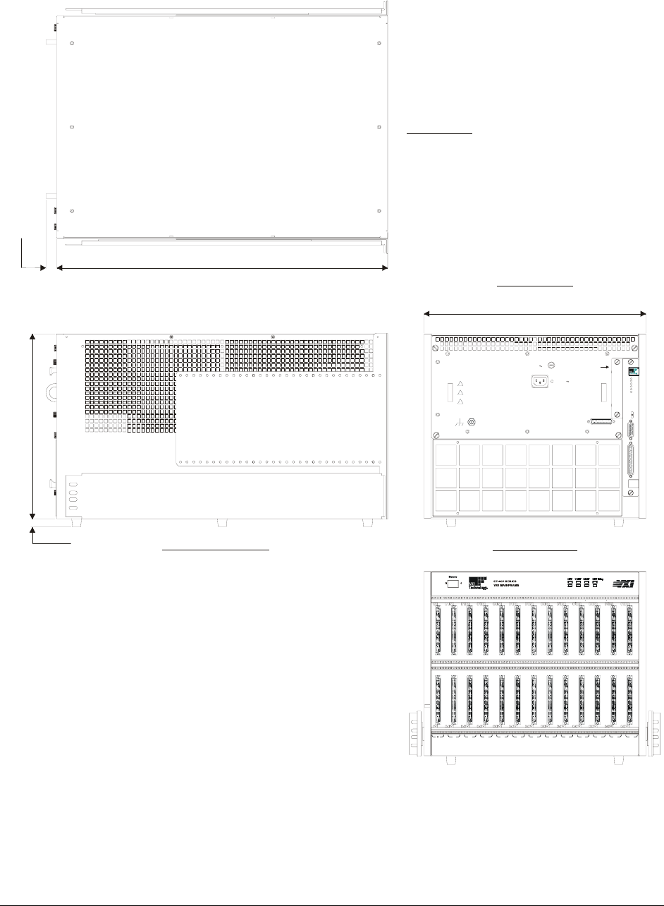
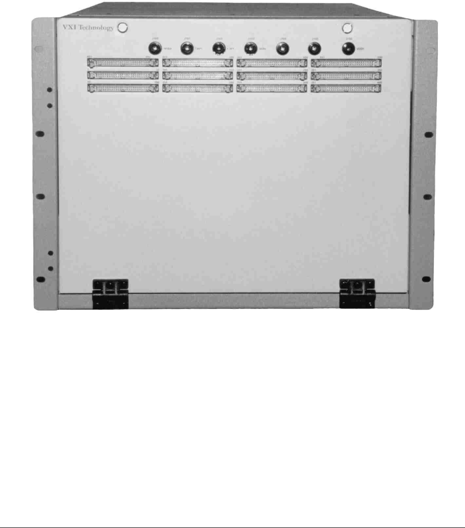
CT-400 MAINFRAME FEATURES
FRONT PANEL FEATURES
POWER SWITCH
Feature 1 When elevated, the mainframe is in standby mode, where power is supplied to
the mainframe, but not to the VXI modules.
When depressed, power is supplied to both mainframe and VXI modules.
VOLTAGE MONITOR INDICATORS
Feature 2 Indicates whether specific backplane voltages are within specifications. See
Figure 1-3 for details.
REAR PANEL FEATURES
MODULE FAN FILTER
Feature 3 Replaceable component that filters the air that cools the plug-in modules.
CHASSIS GROUND TERMINAL
Feature 4 Used to electrical ground the mainframe.
J200 CONNECTOR
Feature 5 AC power receptacle.
F200 CONNECTOR
Feature 6 Fuse location.
J210 CONNECTOR
Feature 7 Monitor / Control Connector.
POWER SUPPLY FAN FILTER
Feature 8 Replaceable component that filters the air that cools the power supply.
MONITOR BOARD / J211 CONNECTOR
Feature 9 Provides monitoring of the mainframe’s operation and environment.
(See Section 1 for more details.)
POWER SUPPLY
Feature 10 Replaceable power supply unit.
J211
J210
PWS
PWS
PWS
PWS
FAN
FAN SPEED
HIGH
VAR
LOW
AMB
TEM P
PWR
VOLT
CUR
SPEED
TEM P
!
WARNING - DO NOT REM OVE T HIS P OWER M ODULE
WHILE THIS INSTRUMENT HAS AC POWER APPLIED
!
WARNIN G -
THE GROUN DING CONNECTION IN THE
POWER CORD MUST BE CONNECTED TO ENSURE
PROTECTION FROM ELECTRICAL SHOC K.
!
WARNING - TO AVOID ELECTRICAL SHOCK, DISCONNECT
AC POWER CORD PRIOR TO REPLACING FUSE.
CAUTION -
FOR CONTINU ED FIRE PROTECTION
REPLACE ONLY WITH A FUSE OF THE CORRECT
VOLTA GE AND R ATING.
J200
100 - 240 VAC
15 A MAX.
47 -63 Hz
REMOV E COVER TO
SERVICE AIR FILTER
J201
MONITOR / CONTROL
F200
15A T 250 (VAC)
01
Voltage Monitors
+5V +12V +24V +5V Stby
-5.2V -12 V -24V -2V
CT-400 SERIES
VXI MAINFRAME
1 2 3 4 5 6 7 8 9 101112
1 2
56 7 8 9
10
4
3
bus
FIGURE 1-2: MAINFRAME FEATURE LOCATIONS
VXI Technology, Inc.
14 CT-400 Introduction
VOLTAGE INDICATOR LEDS
The power supply lines are monitored and displayed on the front panel, providing information
pertaining to the chassis operational status.
01
Voltage Monitors
+5V +12V +24V +5V Stby
-5.2V -12V -24V -2V
CT-400 SERIES
VXI MAINFRAME
123456789101112
bus
Voltage Monitor LEDs
Green
Not Lit
Red
: Within Voltage Specifications
: Under Voltage
: Over Voltage
FIGURE 1-3: FRONT PANEL VOLTAGE INDICATORS
www.vxitech.com
CT-400 Introduction 15
REAR PANEL MONITOR / CONTROL CONNECTOR
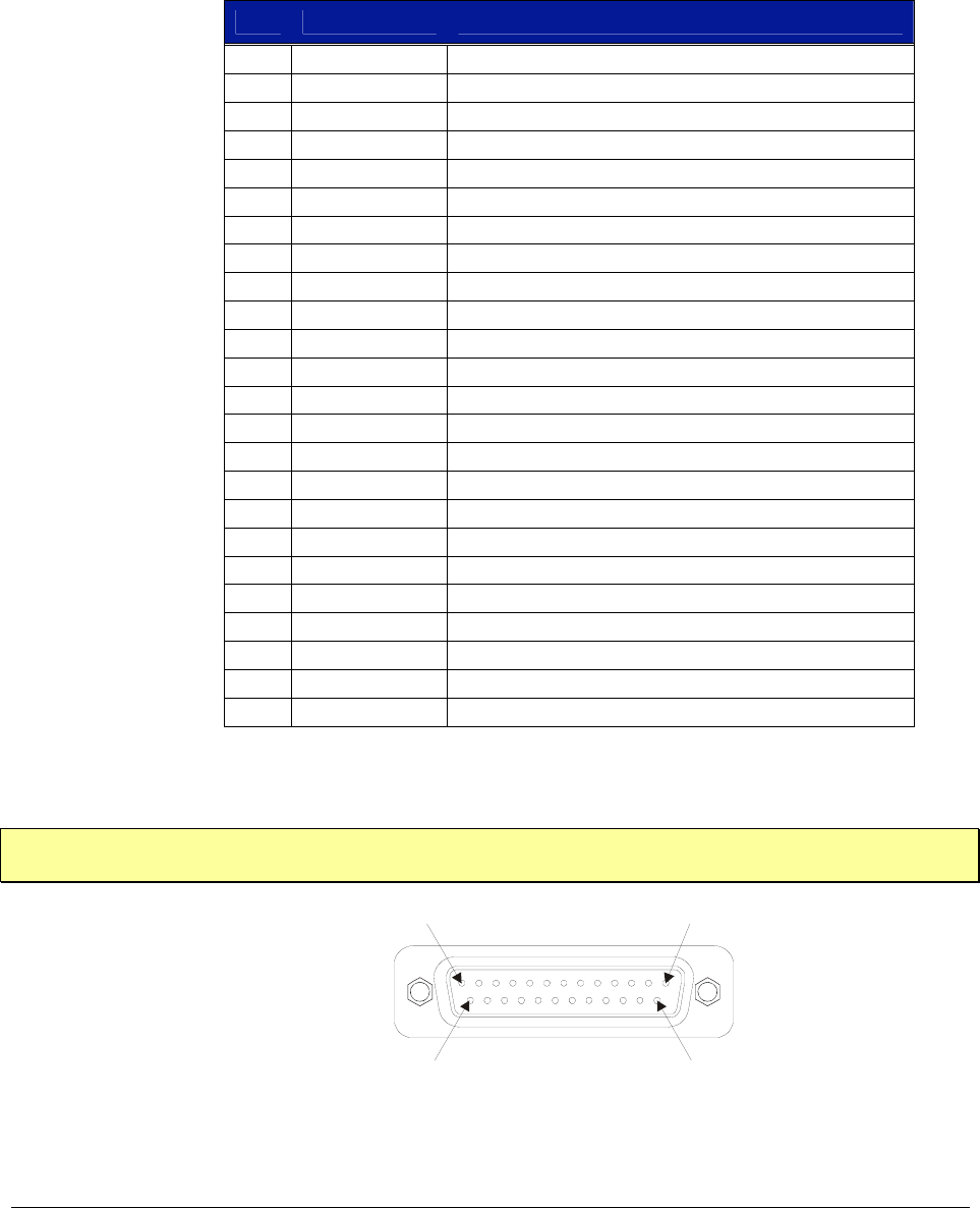
The 25-pin Monitor/Control Connector (see Figure 1-2) provides access to the backplane voltages
and other signals. The following table shows a pinout/signal list along with a brief description of
each. Refer to the pin locations in Figure 1-4.
TABLE 1-1: MONITOR / CONTROL CONNECTOR PINOUT ASSIGNMENTS
PIN SIGNAL DESCRIPTION
1 -24 VMON VXIbus Voltage Monitor Output
2 GND Logic Ground
3 -2 VMON VXIbus Voltage Monitor Output
4 GND Logic Ground
5 +24 IMON Power Supply Current Monitor Output
6 -12 IMON Power Supply Current Monitor Output
7 -2 IMON Power Supply Current Monitor Output
8 -5.2 VMON VXIbus Voltage Monitor Output
9 RSV Reserved
10 +5 STANDBY VXIbus +5 V Standby Input
11 +5 VMON VXIbus Voltage Monitor Output
12 ACFAIL* VXIbus ACFAIL* Input or Monitor Output (see note)
13 RSV Reserved
14 GND Logic Ground
15 -12 VMON VXIbus Voltage Monitor Output
16 +24 VMON VXIbus Voltage Monitor Output
17 +12 VMON VXIbus Voltage Monitor Output
18 +12 IMON Power Supply Current Monitor Output
19 -24 IMON Power Supply Current Monitor Output
20 -5.2 IMON Power Supply Current Monitor Output
21 +5 IMON Power Supply Current Monitor Output
22 +5 STANDBY VXIbus +5 V Standby Input
23 R INHIBIT* Power Supply Remote Inhibit Input
24 GND Logic Ground
TABLE 1-2: MONITOR / CONTROL CONNECTOR PINOUT ASSIGNMENTS
NOTE Refer to VXIbus and VMEbus specifications for details on using the ACFAIL* and SYSRESET*
signals
Pin 13 Pin 1
Pin 25 Pin 14
FIGURE 1-4: DETAIL - MONITOR / CONTROL CONNECTOR PIN LOCATIONS

VXI Technology, Inc.
16 CT-400 Introduction
CT-400 SPECIFICATIONS
GENERAL SPECIFICATIONS
SIZE
16.7" (424.18 mm) W x 14.00" (355.60 mm) H x 25.00" D (635.00 mm)
Thirteen C-size VXIbus card slots
WEIGHT
< 50 lb (11.3 kg)
VXIBUS VERSION
1.4
MTBF
100,000 hr
MTTR
5 min
ENVIRONMENTAL SPECIFICATIONS
OPERATING LOCATION
This chassis should be operated indoors in a controlled environment, protected
from exposure to the elements (i.e. direct sunlight, precipitation, wind, etc.)
TEMPERATURE
Operating
Storage 0 °C to +55 °C
-40 °C to +71 °C
HUMIDITY
Operating
Non-operating
Up to 95% (non-condensing) at up to 30 °C; up to 45% at up to 55 °C
Up to 95% (non-condensing) at up to 55 °C
Altitude
Operating
Non-Operating
15,000 ft (4570 m)
40,000 ft (12,190 m)
Random Vibration*
Operating
Non-Operating
0.27 g-rms total from 5 Hz to 55 Hz
2.28 g-rms total from 5 Hz to 55 Hz
* Three axis, 30 min total, 10 min per axis.
Functional Shock
Operating Half sine, 30 g, 11 ms duration
Meets functional shock requirements of MIL-T-28800E, Type III, Class 5
COOLING SPECIFICATIONS
COOLING REQUIREMENTS
> 100 W/slot
COOLING MODES
Three cooling modes are available for the CT-400 mainframe. High or low
speed cooling modes can be selected by moving the Fan Speed switch at the
rear of the mainframe. The variable cooling speed mode determines fan speed
as a function of ambient temperature a mainframe load. The power supply and
modules are cooled by separate fans.
AIR FLOW PATH
Air is drawn into the mainframe from the rear and is pressurized below the
cards. The air is then distributed across all slots along the total length of each
slot and is exhausted through the top of the mainframe. When the mainframe is
rack mounted, allow approximately 2.0 inches (5.1 cm) of clearance at the top
and rear for proper airflow.
www.vxitech.com
CT-400 Introduction 17
POWER SPECIFICATIONS
POWER
Available
Useable
1630 W
1000 W
DC SUPPLY VOLTAGE
A total of 1000 W may be supplied to the modules with the following
maximum currents:
Voltage Peak Current (IMP) Dynamic Current (IMD)
+5 V 80 A 15 A
-5.2 V 60 A 10 A
-2 V 30 A 5 A
+12 V 17 A 3 A
-12 V 17 A 3 A
+24 V 12 A 4 A
-24 V 12 A 4 A
OUTPUT VOLTAGE
Voltage Allowed Variation Ripple/Noise
DC Load Induced Ripple
Noise
+5 V +0.25 V / -0.125 V 50 mV 50 mV
-5.2 V -0.26 V / +0.125 V 50 mV 50 mV
-2 V -0.10 V / +0.72 V 50 mV 50 mV
+12 V +0.60 V / +0.36 V 50 mV 50 mV
-12 V -0.60 V / +0.36 V 50 mV 50 mV
+24 V +1.20 V / -0.72 V 150 mV 150 mV
-24 V -1.20 V / +0.74 V 150 mV 150 mV
POWER INPUT
Input Voltage
Nominal AC
Frequency
Inrush Current
Input Power
Input Leakage
Input Harmonics
Fuse
90 V– 250 V Operation
207 V– 250 V Operation
100 V ac minimum, 240 V ac maximum
47 Hz - 63 Hz (47 Hz - 440 Hz with increased leakage current and reduced PFC)
< 70 A (cold start or after 1 minute cool down)
1000 W max
< 1.24 MA @ 264 V ac, 53 Hz
Meets EN61000-3-2
15 A, 250 V, slow blow
10 A, 250 V, slow blow
PERIODIC AND RANDOM DEVIATIONS
±24 V
All Others
150 mVP-P
50 mVP-P
AUXILIARY DC OUTPUTS
1.5 A each at all seven supply voltages (fused/self-healing)
POWER SUPPLY
UL, CSA, TUV approved
Shout circuit, over-voltage, reverse voltage and thermal shutdown protection
VXI Technology, Inc.
18 CT-400 Introduction
12345678910
11 12
24.900
(632.46)
TOP VIEW
0.805
(20.440)
LEFT SIDE VIEW
13.900
(353.06)
0.615
(15.620)
* Note: Measurements in parenthesis are in millimeters
REAR VIEW
FRONT VIEW
16.699
(424.15)
J211
J210
PWS
PWS
PWS
PWS
FA N
FA N SPE ED
HIGH
VAR
LOW
AMB
TEMP
PWR
VOLT
CUR
SPEED
TEMP
01
Voltage Monitors
+5V +12 V +24 V + 5V S tby
-5.2 V -12 V -24 V -2V
CT-400 SERIES
VXI MAINFRAME
bus
!
WARNING - DO NOT REMOVE THIS POWER M ODULE
WHILE THIS INSTRUMENT HAS AC POWER APPLIED
!
WARNING -
THE GROUNDING CONNECTION IN THE
POWER CORD MUST BE CONNECTED TO ENSURE
PROTEC TION FRO M ELECTR ICAL SHOCK .
!
WARNING - TO AVOID ELE CTRICAL SHOCK, DISCONNECT
AC POW ER CORD PRIOR TO REPLACING FUSE.
CAUTION -
FOR CONTINUED FIRE PROTECTION
REPLACE ONLY WITH A FUS E OF THE CORRECT
VOLTAGE AND RATING.
J200
10 0 - 240 VAC
15 A MAX.
47 -6 3 Hz
REMOV E COVER TO
SERVICE AIR FILTER
J201
MONITOR / CONTROL
F200
15A T 250 (VAC)
FIGURE 1-5: CT-400 DIMENSIONAL DIAGRAM

www.vxitech.com
CT-400 Introduction 19
CT-400 OPTIONS
OPTIONS
ADJUSTABLE RACK MOUNT FLANGES WITH HANDLES
OPTION 100 These allow the mainframe to be accommodated into any depth rack - either
recessed in the rack up to 10 inches (25.4 cm) or extended out from the rack up
to 5 inches (12.7 cm).
VXIPLUG&PLAY RACK MOUNT KIT
OPTION 101 This allows the CT-400 to be used with VXIplug&play adapters and interfaces.
RACK MOUNT SLIDES
OPTION 102 Mounts the CT-400 in the rack while allowing access by sliding the unit.
TRANSPARENT FRONT DOOR
OPTION 103 Protects the instrumentation and cabling while allowing viewing of the VXIbus
instrument annunciators.
HINGED CUSTOM FRONT PANEL
OPTION 104 A customizable front panel is available that hinges down and mounts to the
front of the CT-400. This option allows custom connectors and small interface
adapters to be mounted directly to the front of the VXIbus mainframe; reducing
cable lengths and improving signal integrity (see Figure 1-9 for an example).
1U CABLE TRAY
OPTION 105 A 1U Cable tray that allows access between the front and rear of the mainframe
and other instruments within the rack.
2U CABLE TRAY
OPTION 106 A 2U Cable tray that allows access between the front and rear of the mainframe
and other instruments within the rack.
BACK PLANE SHIELDS
OPTION 107 Backplane shields improve EMI/RFI performance.
INTERMODULE SHIELDS (12)
OPTION 108 Intermodule shields improve EMI/RFI performance.
VXI Technology, Inc.
20 CT-400 Introduction
FIGURE 1-6: OPTIONS 100 & 106 - MOUNTING FLANGES/HANDLES & 2U CABLE TRAY
www.vxitech.com
CT-400 Introduction 21
FIGURE 1-7: OPTION 106 – 2U CABLE TRAY – REAR VIEW
VXI Technology, Inc.
22 CT-400 Introduction
FIGURE 1-8: OPTIONS 100, 103 & 106 - MOUNTING FLANGES/HANDLES, 2U CABLE TRAY & DOOR
www.vxitech.com
CT-400 Introduction 23
FIGURE 1-9: OPTION 104 - HINGED CUSTOM FRONT PANEL

VXI Technology, Inc.
24 CT-400 Introduction
www.vxitech.com
CT-400 Installation 25
SECTION 2
INSTALLATION
INTRODUCTION
This section includes instructions on CT-400 configuration and installation. When the CT-400 is
unpacked from its shipping carton, the contents should include the following items:
(1) CT-400 Thirteen-Slot Mainframe
(1) CT-400 User’s Manual (this manual)
(1) Power cord
All components should be immediately inspected for damage upon receipt of the unit.
The power cord is the only way to disconnect the CT-400 mainframe from ac power.
Therefore, the power cord must be accessible to the operator at all times. When the CT-400
mainframe is mounted in a system rack, the power cord need not be accessible since the rack
must have its own disconnect device.
POWER REQUIREMENTS
The CT-400 is equipped with auto-ranging power supplies, which automatically sense the line
power value and set themselves accordingly. No voltage switch selection is required. When the
CT-400 is shipped, it is configured for a nominal line voltage of 115 V ac, with a 250 V, 15 A
fuse installed. Fuse ratings are as follows:
90 V - 250 V Operation 15 A, 250 V, Slow Blow
207 V - 250 V Operation 10 A, 250 V, Slow Blow
Do not attempt to change the fuse with the line cord connected. Ensure power is off and the
unit is unplugged before changing the fuse.
Refer to Figure 2-1 for the location of the fuse on the back panel.
VXI Technology, Inc.
26 CT-400 Installation
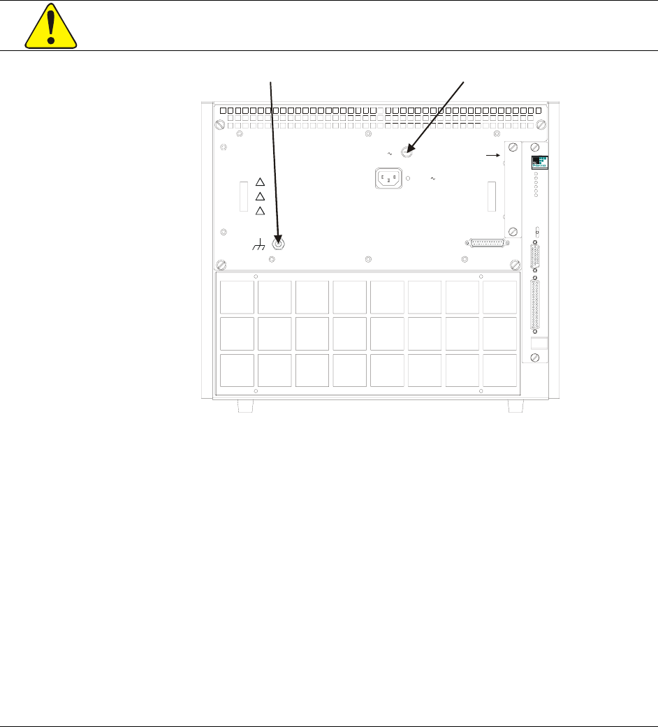
CONNECTING THE MAINFRAME TO EARTH GROUND
The CT-400 is configured at the factory for 115 V ac, 60 Hz. The supplied power cord grounding
conductor provides adequate grounding for this voltage and frequency level. However, if the
CT-400 is to run at anything higher than 63 Hz, the mainframe MUST be connected to earth
ground at the mainframe as follows:
1) Connect a 16 AWG (or larger) wire to the ground terminal located on the rear panel (this
connection is marked by a symbol). Use a grounding lug with a star washer or a toothed lug,
to make this connection. See Figure 2-1.
2) Attach the other end of the wire to a permanent earth ground also using a star washer or a
toothed lug.
To avoid electrical shock, the mainframe ground terminal MUST be connected to earth
ground for frequencies higher than 63 Hz.
J211
J210
PWS
PWS
PWS
PWS
FAN
FAN SPEED
HIGH
VAR
LOW
AMB
TEMP
PWR
VOLT
CUR
SPEE D
TEMP
!
WARNING - DO NOT RE MOVE THIS POW ER MODUL E
WHILE T HIS INSTRUME NT HAS AC POWE R APP LIED
!
WARNING -
THE GROUN DING CONNECTION IN THE
POWER CO RD MUST BE CONNECTE D TO ENSURE
PROTECTION FROM ELECTRICAL SHOCK.
!
WARNING - TO AVOID ELECTRICAL SHOCK, DISCONNECT
AC POWER CORD PRIOR TO REPLACING FUSE.
CAUTION -
FOR CONTINUE D FIRE PROTECTI ON
REPLACE ONLY WITH A FUSE OF THE CORRECT
VOLTAGE AND RATING.
J200
100 - 240 VAC
15 A M AX.
47 - 63 Hz
REMOVE C OVER TO
SERVIC E AIR FI LTER
J201
MONITOR / CONTROL
F200
15A T 2 50 (VAC)
Chassis Ground Terminal Fuse
FIGURE 2-1: FUSE AND GROUND LOCATION
AIR FLOW REQUIREMENTS
The CT-400 must be positioned to provide adequate airflow through the unit. Whether used as a
bench-top or rack mount unit, provide at least a one inch clearance, at the back and sides, to allow
for adequate airflow. Two air filters are installed in the mainframe at the factory, one for the
power supply fan (right side from rear view) and a larger one for the mainframe fans (in the rear at
the bottom). These filters may be removed if additional airflow is required, but only if the air is
filtered at another source within the rack or if it is installed in a clean environment.
www.vxitech.com
CT-400 Installation 27
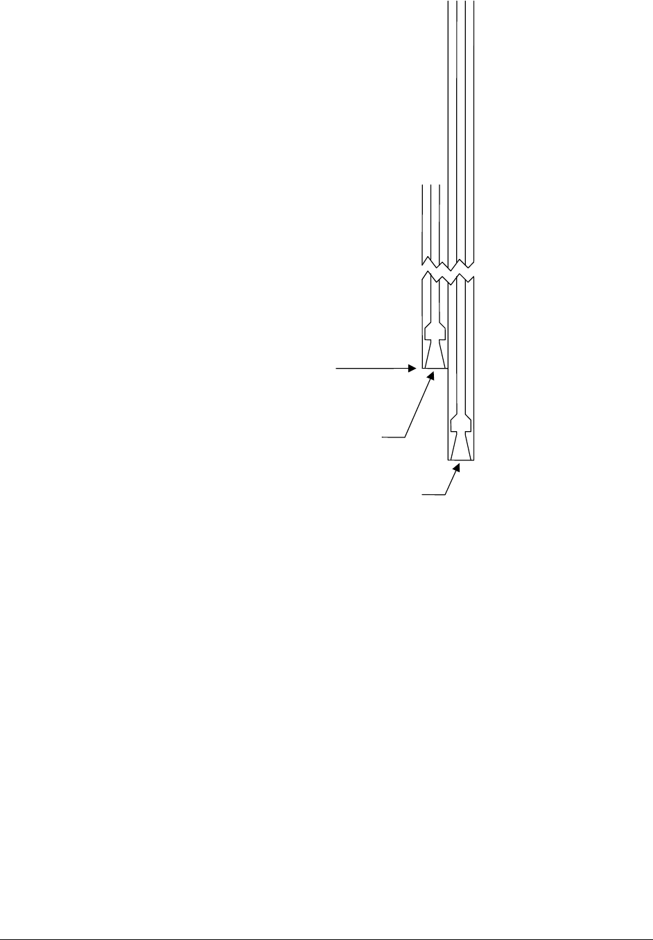
metal strip down
center of shield guide
Front of Mainframe
all plastic card guide
the shield guides are set
back 1" from the card guides
FIGURE 2-2: DETAIL - CARD GUIDE / SHIELD GUIDE
INSTALLING THE CARD SHIELD OPTION
Optional card shields are available for improved EMI/RFI performance (see the CT-400 Options
table). Each card shield option is installed in the shorter card shield guide, to the left of each card
guide. Simply slide the shield into the desired position and then push it backward, towards the
backplane, until the flange on the card shield comes to rest against the front of the shield guide.
INSTALLING BLANKING PANELS
To optimize airflow and cooling performance, install optional blank panels (VTI P/N: 41-000-
007) into any empty slots. Secure with two captive mounting screws.

VXI Technology, Inc.
28 CT-400 Installation
BENCH-TOP CT-400 USE
OVERVIEW
If the CT-400 is to be used as a bench-top mainframe, ensure that adequate spacing is provided for
the mainframe for cooling purposes as delineated in the previous section. The mainframe should
be placed in a climate-controlled area, away from such elements as precipitation, direct sunlight,
etc.
Once installed, the mainframe is not intended to be mobile. If the mainframe must be relocated,
remove all externally connected cables along with the power cord from the mainframe. Two
people are needed to safely move the mainframe to the newly desired location.
www.vxitech.com
CT-400 Installation 29
RACK MOUNTING THE CT-400
OVERVIEW
This section contains instructions for installing the different rack mount options available for the
CT-400 mainframe. After installation of the rack mount options, the mainframe can then be
mounted into an EIA rack. Three different rack mounting options exist for the CT-400 and are
listed below.
Option 100 - Adjustable Rack Mount Flanges with Handles
The adjustable rack mount flanges with handles will allow for instillation of the CT-400 into any
size rack – either recessed in the rack up to 10 inches or extended from the rack up to five inches.
Option 101 - VXIplug&play (VPP-*) Rack Mount Kit
The VXIplug&play rack mount kit allows for the easy installation of VXIplug&play adapters and
interfaces.
Option 102 - Rack Mount Slides
Rack mount slides allow the end user to access the CT-400 while it is mounted in a rack.
ASSEMBLY PREPARATION
Prior to installation, it is recommended that the positioning of the unit in the rack be planned. Do
this by using the rack mount flanges provided as a guide. Place the guides in the desired location
of installation, with the flange holes in line with the “center” holes on the rack’s vertical rail.
Mark this position for reference.
Support rails, provided with the rack or from some other source, are required for the installation
of the CT-400. Position the support rail just below the bottom of the mounting flange. When
properly installed, the horizontal surface of the support rail should be in line with the bottom of
the flange’s mounting location.
DO NOT mount the mainframe in the rack suing only the mounting flanges. Support rails
MUST be used in combination with the mounting flanges for support.
MOUNTING THE MAINFRAME
After installing any of the rack mount options, it is important that, when mounting the mainframe,
two people (or a mechanical lift) are used to move the mainframe. To mount the mainframe, first
remove the four feet from the bottom of the mainframe. Then, using two people, position the
mainframe onto the previously installed support rails. Slide the mainframe back until the flanges
are against the vertical rails in the rack. The mainframe is then secured to the rack’s vertical rails
through the mounting holes in either of the rack mounting options.
To prevent injury when rack-mounting the mainframe, the mainframe should be empty and
two people should lift the mainframe into position in the rack.

VXI Technology, Inc.
30 CT-400 Installation
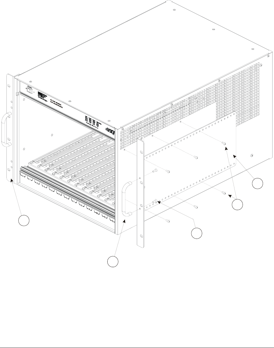
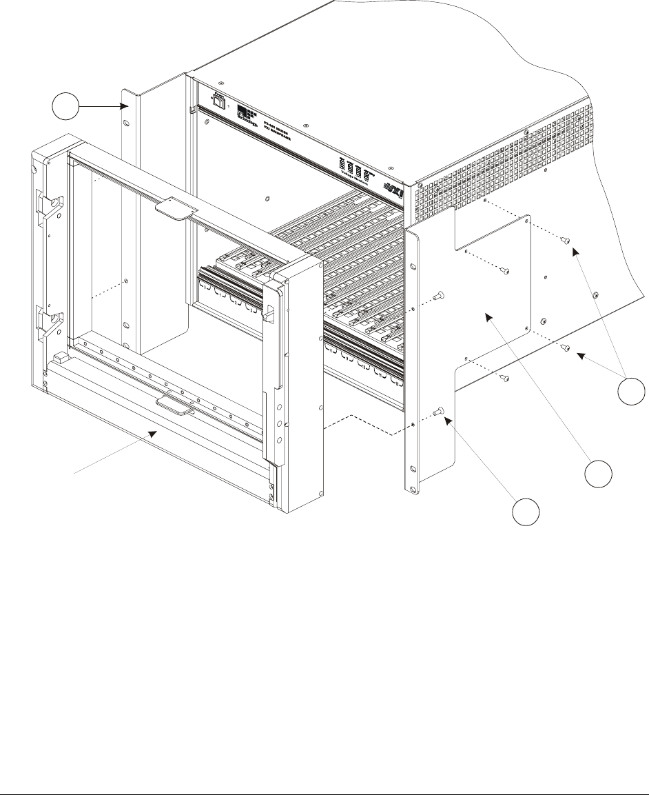
OPTION 100 - ADJUSTABLE RACK MOUNT FLANGES WITH HANDLES
This procedure provides the necessary instructions for installing the adjustable rack mount flanges
with handles.
Required Tools
1) #2 Phillips Screwdriver
2) T15 Torx® screwdriver
Parts List
Item# Qty Description VTI P/N
1 12 Screw, 8-32 x 5/8" Button Head Torx, Black Steel 37-0130-062
2 1 Rack Mount Bracket, Standard, Left Side 41-0221-000
3 1 Rack Mount Bracket, Standard, Right Side 41-0221-001
4 4 Screw, 8-32 x 3/8" Flat Head Phillips, Zinc 37-0080-037
5 2 Handle, Chassis, 1 9/32" x 4", Black Aluminum 37-0134-000
Assembly Procedure
1) Lay the mainframe on a protected work surface on its long side with the voltage monitor
LEDs of the mainframe facing front with the power switch toward the top.
2) Locate the right and left side rack mount brackets. Install the rack mount brackets using
twelve 8-32 x 5/8" button head Torx screws. Refer to Figure 2-3 for guidance. Depending on
how the rack mount brackets are installed, the mainframe can be recessed up to 10" or can be
extended from the rack up to 5".
3) Locate the handles for the rack mount brackets. Use the 8-32 x 3/8" flat head Phillips screws
to install these handles as shown in Figure 2-3.
www.vxitech.com
CT-400 Installation 31
2x
4x
12x
5
2
4
3
1
FIGURE 2-3: ADJUSTABLE RACK MOUNT FLANGE INSTALLATION DIAGRAM

VXI Technology, Inc.
32 CT-400 Installation
OPTION 101 - VXIPLUG&PLAY RACK MOUNT KIT
This procedure provides the necessary instructions for installing a VXIplug&play rack mount kit.
Required Tools
1) #2 Phillips Screwdriver
2) T15 Torx screwdriver
Parts List
Item# Qty Description VTI P/N
1 8 Screw, 8-32 x 5/8" Button Head Torx, Black Steel 37-0130-062
2 1 Rack Mount Bracket, Plug&Play, Right Side 41-0223-000
3 1 Rack Mount Bracket, Plug&Play, Left Side 41-0223-001
4 4 Screw, 10-32 x 7/8", Flat Head Phillips, 82 Deg, Stainless 37-0147-087
Assembly Procedure
1) Lay the mainframe on a protected work surface on its long side with the voltage monitor
LEDs of the mainframe facing front with the power switch toward the top.
2) Locate the right and left side rack mount brackets. Install the rack mount brackets using eight
8-32 x 5/8" button head Torx screws. Refer to Figure 2-4 for guidance. The VXIplug&play
mounting holes must be aligned where all three mounting holes are directly over the holes on
the vertical rails of the rack. In addition, the VXIplug&play mounting flanges should cover
exactly nine full EIA rack units.
3) Once the rack mount kit has been installed, the mounting receptacle can be installed. Please
refer to the instructions provided with the mounting receptacle for assistance in its
installation. This hardware is not provided with Option 101. The 10-32 x 7/8" flat head
Phillips screws are provided for this purpose.
www.vxitech.com
CT-400 Installation 33
Mounting Receptacle
(Supplied By Customer)
8x
4x
1
4
3
2
FIGURE 2-4: VXIPLUG&PLAY RACK MOUNT INSTALLATION DIAGRAM

VXI Technology, Inc.
34 CT-400 Installation
OPTION 102 - RACK MOUNT SLIDES
Rack mount slides allow the end user the ability to easily access the mainframe after it has been
installed into an EIA rack. This option may be used in conjunction with either Option 100 or 101,
or maybe installed and used independently. (Refer to the previous section for Option 100 and 101
installation instructions.)
Required Tools
1) #2 Phillips screwdriver
Parts List
Item# Qty Description VTI P/N
1 1 Slide, Rack Mount, 24" 37-0127-024
2 1 Bracket, Slide, Rear, Use with 37-0127-024 37-0128-000
3 10 Screw, 8-32 x 3/4" Flat Head Phillips, 82 Deg, Stainless 37-0129-075
4 2 Spacer, Rack Slide 41-0220-000
Assembly Procedure
1) Lay the mainframe on a protected work surface on its long side with the voltage monitor LEDs
of the mainframe facing front with the power switch toward the top.
2) Locate the rack slide spacers. Attach the spacers to the mainframe as shown in Figure 2-5
using the screws provided with the kit (5 screws per spacer). Note the positioning of the notch
when installing the spacer.
3) Locate the 24" rack mount slides. Attach these slides to the spacer by sliding the groove of the
rack mount slide over spacer installed onto the mainframe. The notch of the spacer should lock
into the hole of the slide, securing the slide to the mainframe.
www.vxitech.com
CT-400 Installation 35
10x
2x
2x
2x
3
4
2
1
FIGURE 2-5: RACK MOUNT SLIDE INSTALLATION DIAGRAM

VXI Technology, Inc.
36 CT-400 Installation
ADDITIONAL RACK MOUNT OPTIONS
OVERVIEW
This section contains the procedures for installing additional options for the CT-400. The
available rack mounting options are:
Option 103 - Transparent Front Door
The transparent front door provides protection of instruments and cables while permitting the
viewing of VXIbus instrument annunciators.
Option 104 - Hinged Custom Front Panel
The customizable front panel hinges down and mounts on the front of the CT-400. This option
allows custom connectors and small interface adapters to be mounted directly on the front of the
VXIbus mainframe, reducing cable lengths and improving signal integrity.
Option 105/106 - 1U / 2U Cable Trays
Cable trays are available in 1U and 2U depths that allow access between the front and rear of the
mainframe and other instruments within the rack.

www.vxitech.com
CT-400 Installation 37

VXI Technology, Inc.
38 CT-400 Installation
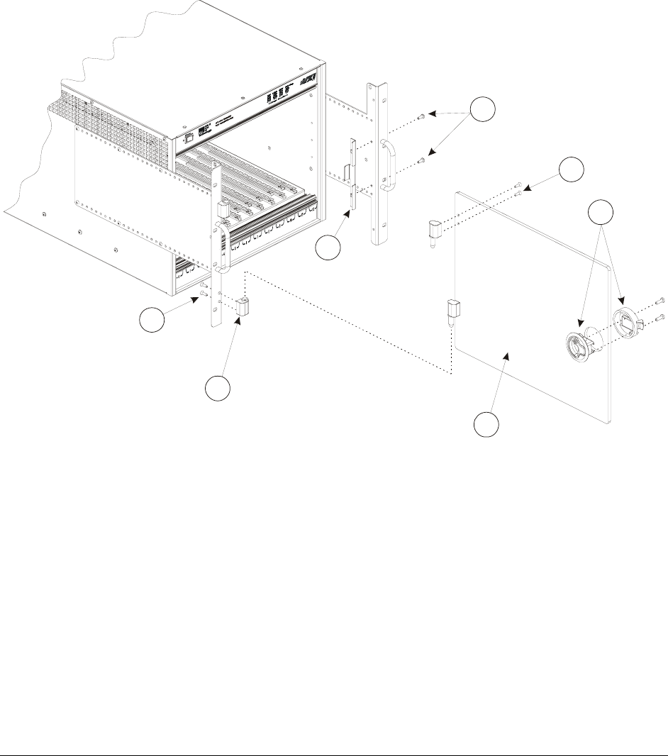
OPTION 103 - TRANSPARENT FRONT DOOR INSTALLATION PROCEDURE
This kit requires Option 100 be installed prior to its installation. Refer to the previous section on
Option 100 for installation instructions.
Required Tools
1) #2 Phillips Screwdriver
Parts List
Item# Qty Description VTI P/N
1 2 Screw, 8-32 x 3/8" Phillips, Sq Cone Sems Zinc 37-0073-037
2 8 Screw, 8-32 x 3/8" Flat Head Phillips, Zinc 37-0080-037
3 1 Flush Pull Latch, 2.0" Dia., Black Polycarbonate 37-0118-000
4 2 Hinge, Nylon Lift Off, Offset Knuckle, Black 37-0131-000
5 1 Latch Bracket, Front Door 41-0225-000
6 1 Front Door, Transparent Bronze 41-0226-000
Assembly Procedure
1) Lay the mainframe on a protected work surface on its long side with the voltage monitor
LEDs of the mainframe facing front with the power switch toward the top.
2) Locate the nylon hinges. Separate the hinges into its male and female components. Attach the
female component to the left rack mount flange using 8-32 x 3/8" flat head Phillips screws as
illustrated in Figure 2-6. Note that the holes of the component are oriented in an upright
position.
3) Take the male components and attach them to the transparent bronze door using the 8-32 x
3/8" flat head Phillips screws provided. Use Figure 2-6 for guidance in orienting this
component.
4) Locate the pull latch. Seat the latch mechanism into the door on the same side as the hinges.
Attach the cover of the latch using the screws provided with the latch.
5) Locate the latch bracket. Attach the bracket to the right rack mount flange using the Phillips
screws indicated on the opposing page.
6) Reconnect the male and female components of the hinge.
www.vxitech.com
CT-400 Installation 39
1
2
3
5
6
2
4
2x
4x
4x
2x
FIGURE 2-6: TRANSPARENT DOOR INSTALLATION DIAGRAM

VXI Technology, Inc.
40 CT-400 Installation
OPTION 104 - HINGED CUSTOM FRONT PANEL INSTALLATION PROCEDURE
This kit includes the hardware found in Option 100 as well as the hardware necessary to install the
hinged custom front panel.
Required Tools
1) #2 Phillips Screw Driver
2) T15 Torx screwdriver
3) 3/8" Open Ended Wrench
Parts List
Item# Qty Description VTI P/N
1 2 Hinge, Adjustable Damping, Black 37-0066-000
2 4 Screw, 8-32 x 3/8" Flat Head Phillips, Zinc 37-0080-037
3 12 Screw, 8-32 x 5/8" Button Head Torx, Black Steel 37-0130-062
4 2 Handle, Chassis, 1 9/32" x 4", Black Aluminum 37-0134-000
5 1 Hinge, Support, Custom Door, Right Side, Nickel 37-0136-000
6 1 Hinge, Support, Custom Door, Left Side, Nickel 37-0136-001
7 1 Rack Mount Bracket, Standard, Left Side 41-0221-000
8 1 Rack Mount Bracket, Standard, Right Side 41-0221-001
9 1 Front Door, Application Specific 41-0229-000
10 1 Lower Support Bracket, App Spec Door 41-0230-000
11 1 Upper Support Bracket, App Spec Door 41-0231-000
12 4 Washer, Split Lock, 8-32 Zinc 37-0013-008
13 4 Nut, Hex, 8-32, Zinc/Steel 37-0030-832
14 2 Screw, 8-32 x 3/8" Pan Head Phillips, Steel/Zinc 37-0074-037
15 2 Washer, Shoulder, 8-32, Nylon 37-0145-008
16 2 Standoff, 3/8" Hex, M/FM x 0.25, 10-32 M, 8-32 FM, SS 37-0146-000
17 12 Screw, 8-32 x 1/4", Truss Head Phillips, Blk Oxide 37-0038-025
18 8 Screw, 8-32 x 3/8" Pan Head Phillips, M/S, Blk Oxide 37-0079-037
Assembly Procedure
1) Lay the mainframe on a protected work surface on its long side with the voltage monitor
LEDs of the mainframe facing front with the power switch toward the top.
2) Locate the right and left side rack mount brackets. Install the rack mount brackets using eight
8-32 x 5/8" button head Torx screws. Refer to Figure 2-7 for guidance. In order for the
custom panel to utilize the support hinges, the mainframe must be recessed by at least 6.5
inches (16.51 cm).
3) Locate the handles for the rack mount brackets. Use the 8-32 x 3/8" Phillips screws to install
these handles as shown in Figure 2-7.
4) Locate the upper and lower support brackets. Attach these brackets to the rack mount flanges
above using the 8-32 x 1/4" black truss head Phillips screws.
5) Attach the standoffs to the rack mount brackets as indicated in Figure 2-7 below.
6) Locate support brackets. Attach the support brackets to the appropriate rack mount flange
using an 8-32 x 3/8" pan head Phillips screw and a nylon washer.
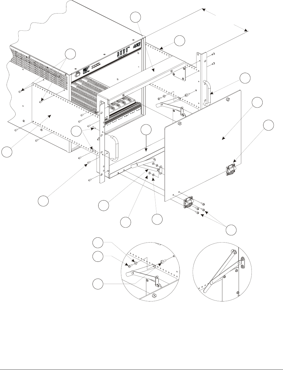
www.vxitech.com
CT-400 Installation 41
7) Locate the adjustable hinges. Attach the hinges to the front door using 8-32 x 3/8" pan head
Phillips screws. Attach the door to the lower support bracket using the same hardware.
8) Attach the door to the support hinges using a nylon washer and an 8-32 x 3/8" pan head
Phillips screws.
6.5” Minimum Distance Required
For Use Of Support Hinge
Hinge Installation
Detail
18
1
9
8
4
17
7
2
3
6
13 12
8x
2x
2x
16
14
10
11
12x
4x
8x
15
2x
4x 4x
FIGURE 2-7: CUSTOMIZABLE FRONT DOOR INSTALLATION DIAGRAM

VXI Technology, Inc.
42 CT-400 Installation
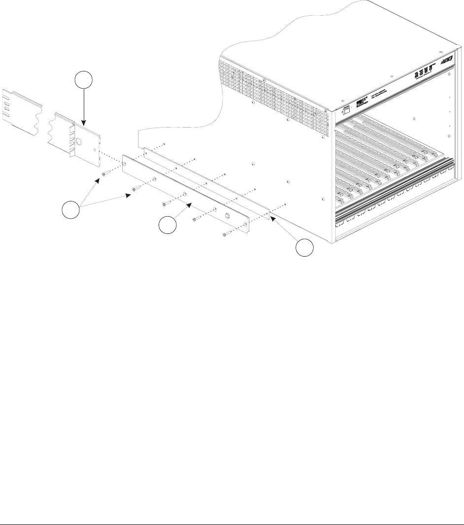
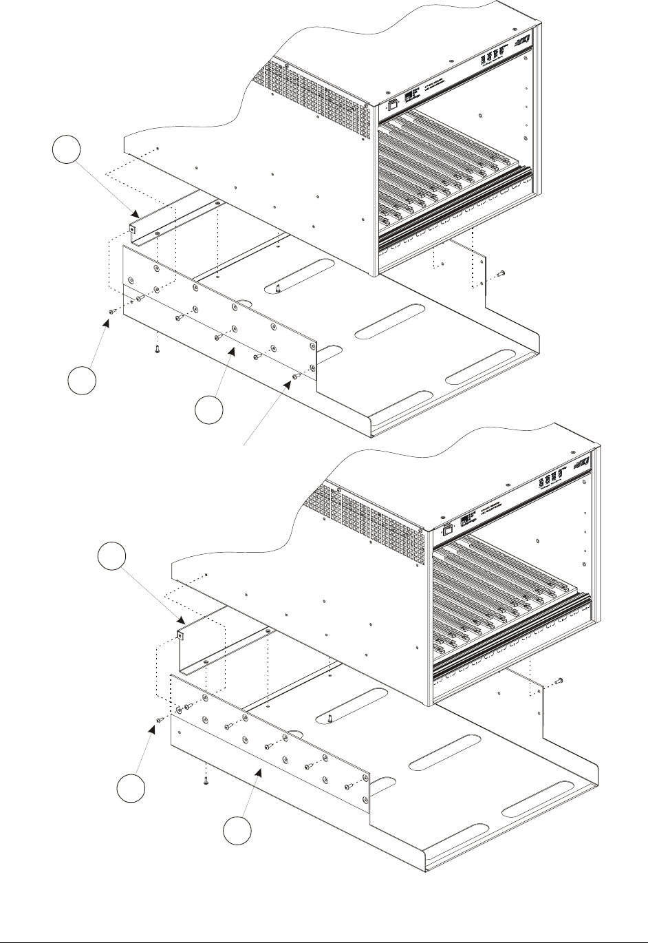
OPTION 105/106 - 1U/2U CABLE TRAYS INSTALLATION PROCEDURE
The 1U/2U cable trays make organizing the cabling associated with the mainframe and modules
more manageable. The cable tray is the same both the 1U and 2U version, with only the height of
the rear panel differentiating between the two.
Required Tools
1) #2 Phillips Screw Driver
Parts List
Item# Qty Description VTI P/N
1 5 Screw, 6-32 x 3/8" Pan Head Ph, Sq Cone Sems Zinc 37-0028-037
2 1
Rear Panel, Wire Tray, User Modifiable, 1U
-or-
Rear Panel, Wire Tray, User Modifiable, 2U
41-0227-000
41-0227-001
3 1 Cable Tray, 1U / 2U Deep 41-0228-000
Assembly Procedure
1) Lay the mainframe on a protected work surface on its long side with the voltage monitor
LEDs of the mainframe facing front with the power switch toward the top.
2) Locate the cable tray. Attach the rear panel (either 1U or 2U) using the screws provided with
kit. See Figure 2-8 for screw locations.
3) Locate the ten screws at the bottom of the side plates and remove. See Figure 2-8 for location.
4) Attach the cable tray to the mainframe using the screws removed in Step 3. This process is
most easily accomplished with the mainframe oriented upside-down.
www.vxitech.com
CT-400 Installation 43
Remove Side Plate Screws (10x) To Install Cable Tray
1
1
3
3
2
2
5x
5x
FIGURE 2-8: 1U (TOP) AND 2U (BOTTOM) CABLE TRAY INSTALLATION DIAGRAMS

VXI Technology, Inc.
44 CT-400 Installation
INSTALLATION OF VXI MODULES
OVERVIEW
After the successful installation of rack mount accessories, the chassis is ready for installation of
the VXIbus base units (i.e. an SMP1100, SMP1200, etc.). It is recommended that the instruments
be installed after rack mount accessories have been installed to avoid any unnecessary physical
strains that may be incurred during the installation of the accessories. Whether single- or double-
wide, the process of installation is simple.
Required Tools
1) Phillips head screw driver
Installation Procedure
Install C-size modules directly into the mainframe as follows:
1) To prevent damage to the module, insure the mainframe is powered off.
2) Insert the module into the mainframe by aligning it with both the upper and lower card guide
of the desired slot. The card guide for the module is the right, longer guide-pair of each guide
set.
3) Gently push the module into the slot until it seats into the backplane connectors. The front
panel of the module should be flush with mainframe.
4) Tighten the mounting screws at the top and bottom of the module.
www.vxitech.com
CT-400 Installation 45
DISCONNECTING THE MAINFRAME
To disconnect the CT-400 from its installation, simply follow the instructions below:
1) Place the mainframe in standby by depressing the power switch.
2) Remove the power cord from the mainframe to ensure that no power is running to the
mainframe.
3) Remove all cabling associated with the VXI modules installed in the CT-400.
4) If the chassis is rack mounted, remove the chassis from the rack by removing the screws that
attach the mainframe to the rack.
5) Rack mount options can be removed from the mainframe at this time if desired.
To avoid electrical shock, ensure power is removed from the mainframe before installing or
uninstalling modules.
All modules are grounded through the mainframe backplane. To ensure a good ground
connection, the module mounting screws must be secure.

VXI Technology, Inc.
46 CT-400 Installation
www.vxitech.com
CT-400 Operation 47
SECTION 3
OPERATION
INTRODUCTION
There are no operating instructions required for the CT-400 VXIbus mainframe. After the
mainframe is installed, operation is completely transparent to the operator. Just plug in the
instruments then power up the mainframe. The power supply lines and mainframe operation are
monitored and displayed to provide user-feedback of correct operation. Additionally, the user can
configure the CT-400 for remote power on operation if desired.
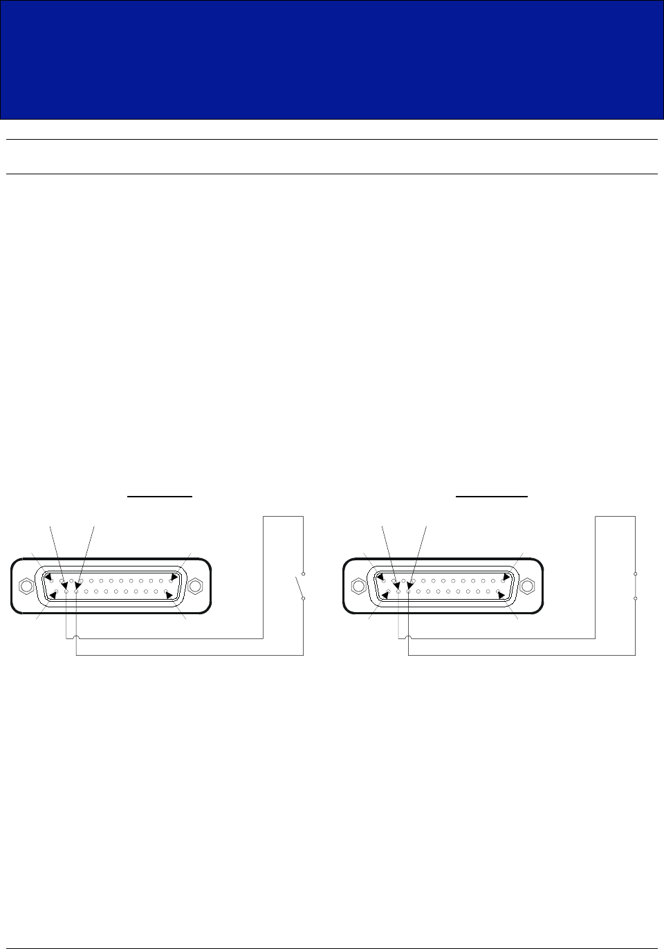
REMOTE POWER CONTROL
If the CT-400 mainframe is to be installed in a remote location, it is possible to apply and remove
power from the unit via the remote power pins located on connector J201. To utilize the remote
power feature, pins 23 and pin 24 should be connected as shown in Figure 3-1. Internally, pin 23
is tied to a +5 V pull-up resistors. When a +5 V level is applied to pin 23, the CT-400 is in its
default state, with the power button indicating the power state of the chassis. When the switch is
closed and pins 23 and 24 are shorted, a 0 V level is applied to pin 23. With the +5 V level
removed, the chassis is then placed in the OFF state.
Pin 24 Pin 23
Pin 13
Pin 25 Pin 14
Pin 1
Pin 24
Pin 23
Power ON
Pin 24 Pin 23
Pin 13
Pin 25 Pin 14
Pin 1
Pin 24
Pin 23
Power OFF
FIGURE 3-1: REMOTE POWER-ON SWITCH WIRING
VXI Technology, Inc.
48 CT-400 Operation
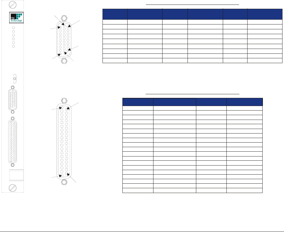
CT-400 MONITOR BOARD
The CT-400 Monitor board provides monitoring of the mainframe’s operation and environment. It
provides the user with access to the seven VXIbus backplane voltages (to power external
circuitry), access to the eight backplane TTL trigger lines (for input and output) and control over
the unit’s cooling operation.
The cooling operation can be selected with the three-position fan speed switch located on the
Monitor board. In the low-speed position, the fans are run at a low speed providing adequate
cooling for most medium to low power modules. Running the fans at low speed will assure
minimum audible noise from the mainframe as well as increasing the life of the fan. In the high-
speed position, the fans are run at their maximum speed for maximum cooling. In the variable-
speed setting, the factory default, the fan speed is adjusted by the power drawn from the power
supply and the ambient temperature. The fan speed is equal to the low-speed setting when no
power is drawn from the backplane and the ambient temperature is 25 °C. As ambient temperature
rises to 45 °C, the fans are increased to the maximum speed in proportion to the temperature. In
addition, as the backplane loading increases from 0 W to 1000 W, the fan speed is increased from
the low speed to the maximum speed. It should be noted that both these factors work together to
set the fan speed.
The CT-400 Monitor board provides all seven VXIbus voltages for user use. Each voltage is
available on connector J211 and is protected by a self-healing fuse rated for 1.0 A per voltage. In
the event that the current rating is exceeded or the line is shorted, the fuse will open and remain
open so long as the fault condition is present. Once the fault is removed, the fuse will restore
power to the connector in a few seconds.
Pin 1
Pin 1
Pin 19
Pin 9
Pin 27
J211
J210
C
ONNECTOR
J211 S
IGNAL
A
SSIGNMENTS
C
ONNECTOR
J210 S
IGNAL
A
SSIGNMENTS
Pin 18
Pin 27
Pin 10 Pin 19
Pin 20
C
ONNECTOR
P
IN
F
UNCTION
C
ONNECTOR
P
IN
F
UNCTION
1 +5 Volts Output 20 Ground
2 -5.2 Volts Output 21 Ground
3 -2 Volts Output 22 Ground
4 +12 Volts Output 23 Ground
5 -12 Volts Output 24 Ground
6 +24 Volts Output 25 Ground
7 -24 Volts Output 26 Ground
8 Reserved 27 Ground
9 AMBTEMPOUT 28 Ground
10 Reserved 29 Ground
11 PWSOTEMP* 30 Ground
12 PWSOPWR* 31 Ground
13 PWSOVOLT* 32 Ground
14 PWSOCUR* 33 Ground
15 AMBOTEMP* 34 Ground
16 FANSPEEDLOW* 35 Ground
17 FANTECH1 36 Ground
18 FANTECH2 37 Ground
19 FAULT*
C
ONNECTOR
P
IN
F
UNCTION
C
ONNECTOR
P
IN
F
UNCTION
C
ONNECTOR
P
IN
F
UNCTION
1
TTLTRIGIN0
10
Ground
19 TTLTRIGOUT0
2
TTLT RIGIN1
11
Ground
20 TTLTRIGOUT1
3
TTLTRIGIN2
12
Ground
21 TTLTRIGOUT2
4
TTLTRIGIN3
13
Ground
22 TTLTRIGOUT3
5
TTLTRIGIN4
14
Ground
23 TTLTRIGOUT4
6 TTLTRIGIN5 15 Ground 24 TTLTRIGOUT5
7 TTLTRIGIN6 16 Ground 25 TTLTRIGOUT6
8 TTLTRIGIN7 17 Ground 26 TTLTRIGOUT7
9 Ground 18 Ground
PWS
PWS
PWS
PWS
FAN
FAN SPEED
HIGH
VAR
LOW
AMB
TEMP
PWR
VOLT
CUR
SPEED
TEMP
FIGURE 3-2: MONITOR BOARD FRONT PANEL AND CONNECTOR PIN LOCATIONS & ASSIGNMENTS
www.vxitech.com
CT-400 Operation 49
CT-400 MONITOR BOARD - SIGNALS
Connector J210
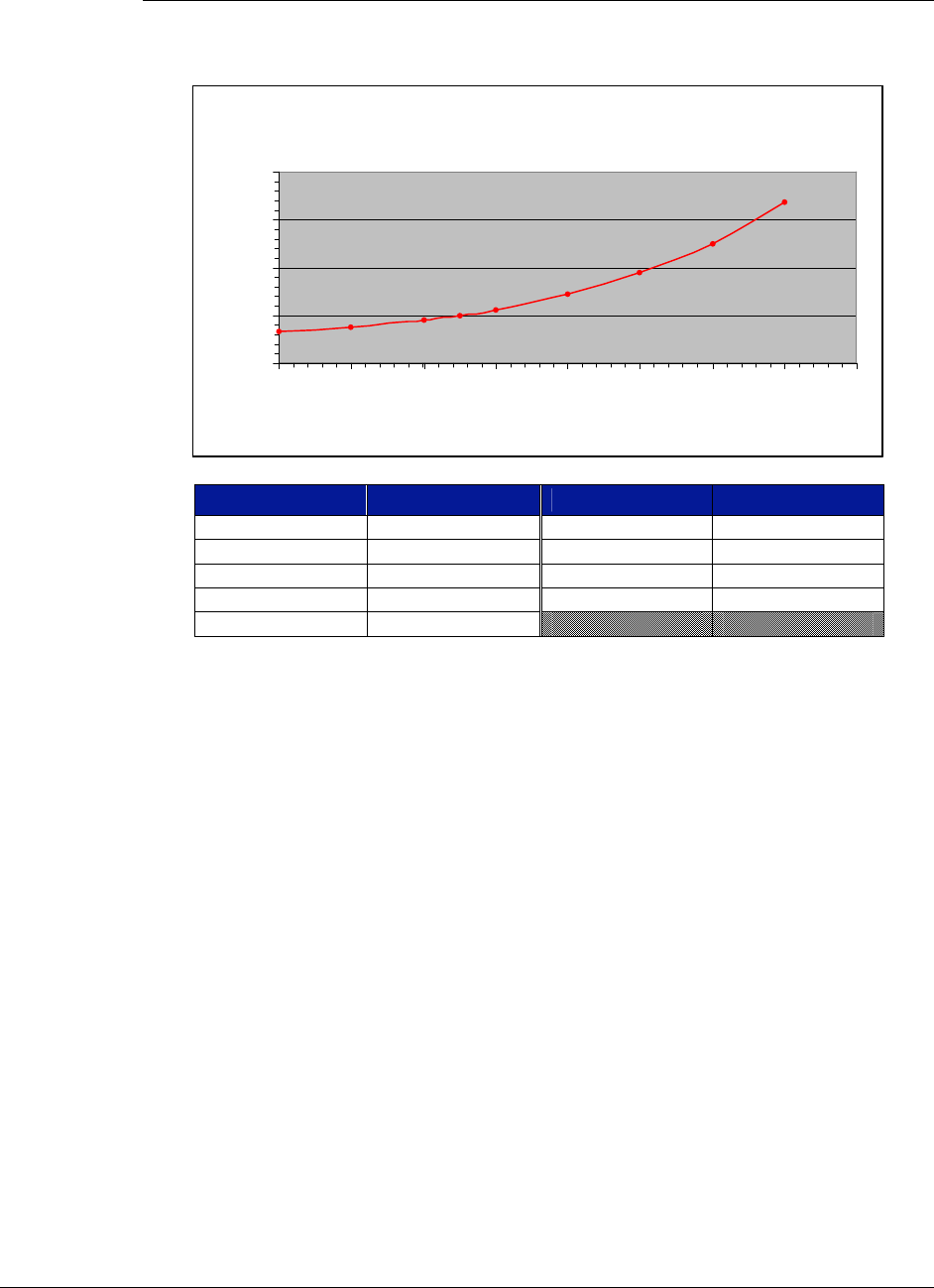
AMBTEMPOUT – Analog output reflecting the temperature of the air entering the mainframe.
This is a non-linearized signal. See Figure 3-3 for a voltage to temperature conversion.
Voltage to Temperature Conversion
0
5
10
15
20
0 1020304050607080
Temperature (°C)
Voltage (V)
Ambient Temp AMBTEMPOUT Ambient Temp AMBTEMPOUT
0 °C 3.27 V 40 °C 7.19 V
10 °C 3.76 V 50 °C 9.44 V
20 °C 4.50 V 60 °C 12.55 V
25 °C 5.00 V 70 °C 16.77 V
30 °C 5.60 V
FIGURE 3-3: TEMPERATURE / VOLTAGE CONVERSION
PWSOTEMP* - This low true open collector output signals a power supply over-temperature
condition. This fault condition occurs when the maximum internal temperature of the power
supply is exceeded. This signal is pulled up to +5 V with a 4.7k resistor internally.
PWSOPWR* - This low true open collector output signals a power supply over-power condition.
This fault will occur when more power is demanded from the power supply than it can provide.
This signal is pulled up to +5 V with a 4.7k resistor internally.
PWSOVOLT* - This low true open collector output signals a power supply over-voltage
condition. This fault occurs when one of the voltages produced by the power supply exceeds its
maximum value. This signal is pulled up to +5 V with a 4.7k resistor internally.
PWSOCUR* - This low true open collector output signals a power supply over-current condition.
This fault occurs when the maximum current of a voltage is exceeded. This signal is pulled up to
+5 V with a 4.7k resistor internally.
AMBOTEMP* - This low true open collector output signals a power supply over-temperature
condition. This fault occurs when the ambient air temperature exceeds 55 °C. This signal is pulled
up to +5 V with a 4.7k resistor internally.

VXI Technology, Inc.
50 CT-400 Operation
FANSPEEDLOW* - This low true open collector output signals a power supply over-
temperature condition. This fault occurs when either of the two fans supplying air to the VXI
instruments speed drops below 1000 RPM. This signal is pulled up to +5 V with a 4.7k resistor
internally.
FANTACH1 - This is a TTL compatible pulse output, whose period is a function of fan number 1
supplying air to the VXI instruments. This signal provides five positive edges per revolution of
the fan. This tachometer output is derived from the current pulses produced when the fans turn;
therefore, when the fan speed is changed abruptly (such as when the fan speed switch is changed)
the output may become unstable momentarily.
FANTECH2 - This is a TTL compatible pulse output, whose period is a function of fan number 2
supplying air to the VXI instruments. This signal provides 5 positive edges per revolution of the
fan. This tachometer output is derived from the current pulses produced when the fans turn;
therefore, when the fan speed is changed abruptly (such as when the fan speed switch is changed)
the output may become unstable momentarily.
FAULT* - This low true open collector output is the logical OR of all the other fault signals. This
signal is pulled up to +5 V with a 4.7k resistor internally.
Connector J211
TTLTRIGINx - TTLTRIGIN0 through TTLTRIGIN7 provide input access to the eight VXIbus
TTLTRIGGER bus lines. Each input is terminated with a 330 Ω resistor to +5 V and a 470 Ω
resistor to ground and is compatible with 74F series TTL logic input levels. Each signal is
buffered and drives its respective TTL trigger line with an open collector driver.
TTLTRIGOUTx - TTLTRIGOUT0 through TTLTRIGOUT7 provide output access to the eight
VXIbus TTL trigger bus lines. Each bus signal is buffered and is compatible with 74F series TTL
logic output levels.

www.vxitech.com
CT-400 Service Information 51
SECTION 4
SERVICE INFORMATION
INTRODUCTION
The CT-400 should operate without the need for service, except for regular cleaning of the air
filter elements. The cleaning schedule is dependant upon the amount of dust in the air, how many
hours the unit is operated and how much airflow is required to adequately cool the installed
instruments.
Note Service should only be performed by qualified personnel.

VXI Technology, Inc.
52 CT-400 Service Information
CLEANING THE AIR FILTERS
Two air filters are present on the CT-400: a module fan filter and a power supply fan filter.
Keeping these filters clean is important in maintaining an adequate air flow through the
mainframe and over the power supply. The air filters can be cleaned in the following manner.
Cleaning the Power Supply Fan Filter
1) Power off the mainframe and remove the power cord.
2) Locate the metal cover plate to the right of the power cord connector and fuse.
3) Loosen the two thumbscrews holding the cover plate and remove it.
4) Slide the power supply filter element out of the slot underneath the cover plate.
5) Blow the dust and dirt out of the air filter element using compressed air or, optionally, use
water and a mild soap.
6) If water and soap are used, make sure to rinse the element of all soap and allow it to dry
before reinstalling it in the mainframe.
7) Reinstall the air filter element and the cover plate and tighten the thumbscrews.

www.vxitech.com
CT-400 Service Information 53
Cleaning the Module Fan Filter
1) Power off the mainframe and remove the power cord.
2) Locate the metal air filter cover at the bottom half of the mainframe.
3) Remove the four screws holding it in place and remove the cover and the filter element.
4) Blow the dust and dirt out of the air filter element using compressed air or, optionally, use
water and a mild soap.
5) If water and soap is used, make sure to rinse the element of all soap and allow it to dry before
reinstalling it in the mainframe.
6) Reinstall the air filter element and cover and reinstall the screws.
VXI Technology, Inc.
54 CT-400 Service Information
POWER SUPPLY REPLACEMENT PROCEDURE
In the event that the cooling fans or power supply must be replaced, they are contained in a single,
easy to remove module. Replacement of the power supply can be accomplished as follows:
1) Power off the mainframe and remove the power cord.
2) Locate four thumbscrews on the rear of the mainframe and loosen all four.
3) Locate two handles on the power supply and firmly pull the module straight back and
remove.
4) Locate the replacement power supply module and install it into the mainframe.
5) Seat the power supply module firmly in place and finger tighten the four thumbscrews.
6) Verify that the front panel power switch is in the off position and reattach the power cord.
Before removing the power supply unit, insure that the mainframe is in a secure location
and will not tip. Service should only be performed by trained personnel.

VXI Technology, Inc.
CT-400 Index 55

VXI Technology, Inc.
CT-400 Index 57
INDEX
A
air filters .............................................................................26, 51, 52
cleaning ..............................................................................52, 53
airflow ......................................................................... 12, 16, 26, 51
B
backplane..................................................................................12, 44
backplane voltages ...................................................................15, 48
base unit installation.......................................................................44
bus grant .........................................................................................12
bus lines ..........................................................................................50
C
card guide .......................................................................................44
card shield.......................................................................................27
cooling ............................................................................................27
cooling operation............................................................................48
D
dimentions ......................................................................................18
disconnecting the mainframe .........................................................45
dynamic current..............................................................................17
E
earth ground....................................................................................26
F
fan speed.........................................................................................48
front panel.......................................................................................12
fuse .................................................................................................17
fuse rating .......................................................................................25
G
grounding .......................................................................................26
J
J201 connector................................................................................47
L
line frequencies ..............................................................................12
line power .......................................................................................25
M
mainframe features .........................................................................13
Monitor / Control Connector..........................................................15
monitor board .................................................................................48
MTBF .............................................................................................16
MTTR .............................................................................................16
O
operation ...................................................................................13, 48
options ............................................................................................19
over-current condition....................................................................49
over-power condition .....................................................................49
over-temperature condition ............................................................49
over-voltage condition ...................................................................49
P
peak current....................................................................................17
power supply .................................................................................. 12
replacement ..............................................................................54
power supply lines ......................................................................... 47
R
rack mount...................................................................................... 30
remote power..................................................................................47
remote power control .....................................................................47
S
signals............................................................................................. 15
specifications......................................................................16, 17, 19
cooling...................................................................................... 16
environmental........................................................................... 16
general ...................................................................................... 16
power........................................................................................17
supply over-temperature condition ................................................49
T
tachometer output........................................................................... 50
temperature..................................................................................... 49
TTLTRIGGER line ........................................................................ 50
V
voltage ............................................................................................17
VXIbus ...............................................................................12, 48, 50
W
WEEE............................................................................................... 7
