Vytek G2BT Sonik G2BT Base Transmitter User Manual G2BT PRD
Vytek Inc Sonik G2BT Base Transmitter G2BT PRD
Vytek >
manual

Sonik G2BT Base Transmitter User Manual
March 14, 2002 1 7M487C4
2nd Generation Base Transmitter
(G2BT)
User Manual

Sonik G2BT Base Transmitter User Manual
March 14, 2002 2 7M487C4
Vytek Wireless, Inc.
Wireless Products Division
2310 Cousteau Court
Vista, CA 92083
(760) 536-1000

Sonik G2BT Base Transmitter User Manual
March 14, 2002 3 7M487C4
Table of Contents
1 Foreword ....................................................................................................................................... 6
1.1 General Information .................................................................................................. 6
1.2 Computer Software Copyrights................................................................................. 6
1.3 Warnings!.................................................................................................................. 8
1.4 Human Exposure....................................................................................................... 8
2 General Overview.......................................................................................................................... 9
2.1 G2BT Paging Transmitter Overview ........................................................................ 9
2.2 Cabinet Layout/Component Identification................................................................ 9
2.2.1 AC Distribution Module.................................................................................... 9
2.2.2 Amplifier Power-Supplies............................................................................... 10
2.2.3 CE Chassis................................................................................................... 10
2.2.4 Amplifier Indicators ........................................................................................ 10
3 Specifications .............................................................................................................................. 12
3.1 RF Specifications .................................................................................................... 12
3.2 Network & Protocol Specifications ........................................................................ 12
3.3 Power Specifications............................................................................................... 12
3.4 Mechanical Specifications....................................................................................... 12
3.5 Communications Interface Specifications............................................................... 13
3.6 Environmental Specifications ................................................................................. 13
4 Electrical RequirEments.............................................................................................................. 14
5 Site Planning ............................................................................................................................... 15
6 Installation................................................................................................................................... 16
6.1 Cabinet Grounding .................................................................................................. 16
6.2 Antenna Connections .............................................................................................. 16
6.2.1 GPS.................................................................................................................. 16
6.2.2 Transmitter RF ................................................................................................ 17
6.2.3 Satellite Receiver............................................................................................. 18
6.3 Network Connections.............................................................................................. 18
7 Operation..................................................................................................................................... 19
7.1 Powering Up the System ......................................................................................... 19

Sonik G2BT Base Transmitter User Manual
March 14, 2002 4 7M487C4
7.2 Connecting a terminal ............................................................................................. 19
7.2.1 Bootloader ....................................................................................................... 20
7.2.2 Application...................................................................................................... 21
7.3 Quick-Start Configuration....................................................................................... 22
7.3.1 Distribution: Incoming MDP configuration.................................................... 22
7.3.2 Transmission: Outgoing Reflex configuration................................................ 22
7.3.3 Network configuration .................................................................................... 23
7.3.4 Important Alarm Thresholds (if default of 20 minutes is not desired) ........... 23
7.3.5 Clear Alarms & Alarm Logs ........................................................................... 23
8 SUBSYSTEMS ........................................................................................................................... 24
8.1 G2BT Control Chassis ............................................................................................ 24
8.1.1 CE Backplane.................................................................................................. 25
8.2 CE Power Supply ....................................................................................................34
9 User Interfaces............................................................................................................................. 35
9.1 Command Line Editor............................................................................................. 35
9.2 Console.................................................................................................................... 35
9.3 Telnet and Console Port User Interface .................................................................. 35
10 SW Download Process ................................................................................................................ 37
10.1 Receive software download file ..............................................................................37
10.2 Write software download file into Flash memory................................................... 37
10.3 Cutover to the new version of downloaded software.............................................. 38
11 Power Control ............................................................................................................................. 39
11.1 Introduction ............................................................................................................. 39
11.2 Configuration Monitoring ....................................................................................... 39
11.3 Power Control Algorithm........................................................................................ 39
11.4 Power Cutback and Shutdown ................................................................................ 40
12 Command Line User Interface .................................................................................................... 42
12.1 Conventions............................................................................................................. 42
12.2 Command List......................................................................................................... 43
12.2.1 Alarm............................................................................................................... 43
12.2.2 CAlibration...................................................................................................... 44
12.2.3 CLock.............................................................................................................. 45
12.2.4 CONSole... ...................................................................................................... 45

Sonik G2BT Base Transmitter User Manual
March 14, 2002 5 7M487C4
12.2.5 Cutover............................................................................................................ 46
12.2.6 Distribution...................................................................................................... 46
12.2.7 Download… .................................................................................................... 47
12.2.8 EXCiter............................................................................................................ 48
12.2.9 EXIt ................................................................................................................. 49
12.2.10 Flash... ........................................................................................................... 49
12.2.11 Gps... ............................................................................................................. 49
12.2.12 Log… ............................................................................................................ 50
12.2.13 Network…..................................................................................................... 50
12.2.14 PA….............................................................................................................. 51
12.2.15 PS… .............................................................................................................. 52
12.2.16 PWrsupply…................................................................................................. 53
12.2.17 Reset….......................................................................................................... 53
12.2.18 SNmp…......................................................................................................... 54
12.2.19 STatistics… ................................................................................................... 54
12.2.20 THreshold….................................................................................................. 55
12.2.21 TRACe… ...................................................................................................... 56
12.2.22 TRANsmission….......................................................................................... 57
12.2.23 Version… ...................................................................................................... 58
12.2.24 Watch ............................................................................................................ 59
13 Alarms and Management............................................................................................................. 60
13.1 Alarm management ................................................................................................. 60
13.1.1 Alarm Processing ............................................................................................ 60
13.1.2 Alarm Types.................................................................................................... 62
13.2 Management information base (mib) ...................................................................... 66
14 Factory Default Values................................................................................................................ 67

Sonik G2BT Base Transmitter User Manual
March 14, 2002 6 7M487C4
1 FOREWORD
1
1
1.
.
.1
1
1
G
G
GE
E
EN
N
NE
E
ER
R
RA
A
AL
L
L
I
I
IN
N
NF
F
FO
O
OR
R
RM
M
MA
A
AT
T
TI
I
IO
O
ON
N
N
The information in this manual is preliminary to the production release of the
G2BT tranmistter. It is to be used to guide the user in the operation of the
equipment, but has not been reviewed for accuracy. No responsibility is assumed
for inaccuracies. Vytek Wireless reserves the right to make changes to any product
discussed hearin. Vytek does not assume any liability arising from the application
or use of any product or circuit described herin. Neither does Vytek convey any
license under any patents or rights of others.
Refer questions concerning the contents of this manual to:
Vytek Wireless, Inc.
Wireless Product Division
2310 Cousteau Ct
Vista, CA 92083
760-536-1000
email: techsupport@sonik.com
1
1
1.
.
.2
2
2
C
C
CO
O
OM
M
MP
P
PU
U
UT
T
TE
E
ER
R
R
S
S
SO
O
OF
F
FT
T
TW
W
WA
A
AR
R
RE
E
E
C
C
CO
O
OP
P
PY
Y
YR
R
RI
I
IG
G
GH
H
HT
T
TS
S
S
This manual covers the following products:
Models: G2BT NPCS transmitter
Copyright 2001 by Vytek Wireless, Inc. This manual is Copyrighted by Vytek Wireless, Inc .
and may be reproduced for distribution with the G2BT as long as the manual remains intact, in its
entirety, with all Copyright, Intellectual Property, and Trademark notices.
This product contains copyrighted material.
This product from Vytek Wireless, Inc. contains intellectual property Vytek Wireless, Inc. It also
contains copyrighted material, to which Vytek Wireless, Inc. is the owner of the copyright.
Unless expressly agreed to in writing, no one may copy, disassemble, or distribute in any form,
any computer readable information contained within this product, and in particular information
contained within the EEPROM, EPROM, or ROM memory circuits. All rights, title, and

Sonik G2BT Base Transmitter User Manual
March 14, 2002 7 7M487C4
copyrights to the software or firmware in this product are owned by Vytek Wireless, Inc. Vytek
reserves all rights not expressly granted to the purchaser of this product.

Sonik G2BT Base Transmitter User Manual
March 14, 2002 8 7M487C4
1
1
1.
.
.3
3
3
W
W
WA
A
AR
R
RN
N
NI
I
IN
N
NG
G
GS
S
S!
!
!
WARNING !
This device has not yet been approved by the FCC and may not be sold or marketed until such
approval is obtained. Changes or modifications to this device that are not expressly approved by
Vytek Wireless are prohibited and could void the user’s warranty and possibly his authority to operate
this product.
DO NOT allow the antenna to come close to or touch the eyes, face, or any exposed body
parts while the radio is transmitting.
DO NOT operate the transmitter unless it is properly connected to a suitable antenna or
dummy load.
DO NOT apply power to the transmitter unless it is properly connected to a suitable
antenna or dummy load.
DO NOT operate the radio near electrical blasting caps.
DO NOT operate this product near explosives or near explosive gasses.
DO NOT operate the radio unless it has been installed and inspected by a qualified radio
technician.
DO NOT let children operate transmitter equipment.
DO NOT defeat the ground connection or polarization provisions of the equipment.
DO NOT allow the antenna used by this product to come within 6 meters of any human.
1
1
1.
.
.4
4
4
H
H
HU
U
UM
M
MA
A
AN
N
N
E
E
EX
X
XP
P
PO
O
OS
S
SU
U
UR
R
RE
E
E
This equipment can radiate large amounts of RF energy. It is designed to use an antenna
permanently fixed mounted to an outdoor structure. The selected area of this structure should
prevent personnel from inadvertently being closer to the antenna than six meters. It is the
responsibility of the user to install and use this equipment in the proper manner. It should be
installed and maintained by trained technicians only. Licensees of the FCC using this equipment
are responsible for insuring that its installation and operation comply with FCC regulations
designed to limit human exposure. See FCC Rules part 1, section 1.1310 as published in CFR part
47.

Sonik G2BT Base Transmitter User Manual
March 14, 2002 9 7M487C4
2 GENERAL OVERVIEW
2
2
2.
.
.1
1
1
G
G
G2
2
2B
B
BT
T
T
P
P
PA
A
AG
G
GI
I
IN
N
NG
G
G
T
T
TR
R
RA
A
AN
N
NS
S
SM
M
MI
I
IT
T
TT
T
TE
E
ER
R
R
O
O
OV
V
VE
E
ER
R
RV
V
VI
I
IE
E
EW
W
W
The Sonik Second Generation Base Transmitter (G2BT) is a ReFlextm paging transmitter for the
900 MHz frequency band. It is a multi-carrier design, based on the original Motorola Base
Transmitter (BT). It Features:
FEATURES
• Multi-carrier linear transmitter with 1-4 simultaneous, independent carriers.
• Reduced overall systems cost with an Sat RX and Ethernet port.
• ReFLEX25 and ReFLEX50 compatible.
• Existing BT features with enhancements to networking, alarming, management, and
reliability.
• Transmit data from Satellite controller interface.
• High reliability100W and 400W models, useful in multi-carrier or single-carrier systems
(one-way or Oasis type systems)
• Reduced size, weight, and power consumption.
• Modular design for easy upgrading and field service.
• GPS receiver generates precise frequency and timing
• SNMP provides network control and alarming
• Software updates may be downloaded over network or via front panel console port
• Generic RS485 interface to allow for other Satellite interfaces
• Enhanced 64 Kbps satellite link data rate
2
2
2.
.
.2
2
2
F
F
FR
R
RO
O
ON
N
NT
T
T-
-
-P
P
PA
A
AN
N
NE
E
EL
L
L
C
C
CO
O
ON
N
NT
T
TR
R
RO
O
OL
L
LS
S
S
2.2.1 AC ON/OFF
Located on the AC Distribution panel, are two circuit breakers. They are used to turn the AC
power to the unit off or on. The left one is the MAIN AC breaker, and switches both sides of the
240VAC power. The right breaker is the 125VAC circuit breaker, and switches the 125VAC
outlets on the front and rear of the AC Distribution Panel.
CAUTION!

Sonik G2BT Base Transmitter User Manual
March 14, 2002 10 7M487C4
If there is an internal AC Uninterruptable Power Supply in the station, there still may be AC
power applied to some sub-systems when both of the circuit-breakers on the front of the unit are
turned off!
The control-equipment chassis has its own battery back-up and will continue to run, even after the
AC power is switched off with the front-panel circuit breakers. You must switch it off with the
On/OFF switch on the front of the CE Power Supply.
2.2.2 AMPLIFIER POWER-SUPPLY SWITCHES
Located on the front of each amplifier’s power supply, is a small AC power switch. There are 4
switches, one for each power supply. These switches turn the AC to each individual amplifier on
or off. In general, they should always be left in the ON position. All 4 amplifier power supplies
must be turned on before the station can transmit. Transmitting with less than 4 power supplies
turned on will cause an alarm, and the station may-not work properly.
2
2
2.
.
.3
3
3
F
F
FR
R
RO
O
ON
N
NT
T
T-
-
-P
P
PA
A
AN
N
NE
E
EL
L
L
I
I
IN
N
ND
D
DI
I
IC
C
CA
A
AT
T
TO
O
OR
R
RS
S
S
2.3.1 AMPLIFIER INDICATORS
Status LED Green=Normal operation
Amber=Fault (hot, overdrive,…)
Red=Off-line (either hard-failed or taken off-line by the operator)
TX LED Lights green when more than 10 watts of RF are output from the amplifier
2.3.2 AMPLIFIER POWER SUPPLY INDICATORS
2.3.3 CE CHASSIS INDICATORS
There are 4 LEDs on the front of the System Controller Module (SCM) in the control
chassis. The funtion of the LEDs on this module are as follows:

Sonik G2BT Base Transmitter User Manual
March 14, 2002 11 7M487C4
GREEN ● AMBER ● RED ● OFF ●
Power LED Online
Warming up or unit is
off-line. It is also
amber when the
network paging feed
is disabled.
Diagnostics mode.
Sync LED Locked
(GPS SYNC
ACQUIRED state)
Holding
(GPS SYNC LOST
state)
Searching
(GPS OPEN
SEARCH state)
Alarm LED Station OK Minor Alarm Major Alarm
Flashing = Critical
Alarm
Booting up
Network
LED
MDP Data is being
received No MDP Data
is being
received

Sonik G2BT Base Transmitter User Manual
March 14, 2002 12 7M487C4
3 SPECIFICATIONS
3
3
3.
.
.1
1
1
R
R
RF
F
F
S
S
SP
P
PE
E
EC
C
CI
I
IF
F
FI
I
IC
C
CA
A
AT
T
TO
O
OI
I
IN
N
NS
S
S
Function Specification
Operating Frequency Range 929.00 – 941.00 MHz
Modulation Modes Per ReFLEX 2.7 and ReFlex 50 specs:
4 level FSK, 3200 & 6400 bps
2 level FSK, 1600 & 3200 bps
Launch Time Delay Programmable, 1μS to 1 mS
Encoder Clock Stability +/- 2.5 ppm
Launch Time Accuracy 1 μS
Launch Time Resolution 1 μS
Transmit Rise Time <= 10 mS
Transmit ON Timing Rated power before first sync symbol
Transmit Off Timing <= -13 dBm within 2.5 mS
Sub-Channel Spacing 10 KHz or 12.5 KHz
Modulation Bandwidth 10 to 50 KHz
Number of Sub-Channels One to Four
Power Amplifier Type Options Class A or Class C, Field Installable
Frequency Accuracy +/- 1 Hz (when locked to GPS)
Frequency Offset Range +/- 500 Hz
Frequency Offset Resolution 1 Hz
GPS Time Sync Accuracy 500 nS
GPS Sync Freewheeling Time > 30 minutes (typical)
Amplifier Power Level Options 100 or 400 watts (multi-carrier linear mode)
250 watts (single-carrier non-linear mode)
3
3
3.
.
.2
2
2
N
N
NE
E
ET
T
TW
W
WO
O
OR
R
RK
K
K
&
&
&
P
P
PR
R
RO
O
OT
T
TO
O
OC
C
CO
O
OL
L
L
S
S
SP
P
PE
E
EC
C
CI
I
IF
F
FI
I
IC
C
CA
A
AT
T
TI
I
IO
O
ON
N
NS
S
S
Transmitter Protocol ReFlex Version 2.7 and ReFlex 50
Satellite Receiver Interface Protocol Mtel Distribution Protocol (MDP)
Network Interface Protocol TCP/IP over IEEE 802.3 10baseT Ethernet
MDP Packet Receipt Time >= 200ms
Launch Timing Launch based on GPS time + delay
Command & Control Protocol SNMP Version 1 via UDP
Software Download Protocol TFTP via UDP over Network,
XMODEM or YMODEM via
Front Panel Console
3
3
3.
.
.3
3
3
P
P
PO
O
OW
W
WE
E
ER
R
R
S
S
SP
P
PE
E
EC
C
CI
I
IF
F
FI
I
IC
C
CA
A
AT
T
TI
I
IO
O
ON
N
NS
S
S
Sub-Systems with Battery Backup Controller operation for 15 minutes
Input Voltage 1 phase 176-264 VAC, 50-60Hz
Input power consumption 3500 watts max
AC Input Connection 240VAC, Single phase, NEMA L14-30P
3
3
3.
.
.4
4
4
M
M
ME
E
EC
C
CH
H
HA
A
AN
N
NI
I
IC
C
CA
A
AL
L
L
S
S
SP
P
PE
E
EC
C
CI
I
IF
F
FI
I
IC
C
CA
A
AT
T
TI
I
IO
O
ON
N
NS
S
S
EMP/Lightning Protection Antennas: SatRx, GPS, Transmitter
AC power, lease line
RF Connector 7/16" Type Female
GPS Connector "N" Type Female

Sonik G2BT Base Transmitter User Manual
March 14, 2002 13 7M487C4
Satellite Receiver Connector “F” Type Female
Ethernet LAN Connector RJ-45 [10baseT]
Weight < 500 pounds
Front Panel Console Connector DB-9 Female
Connector Locations Accessible, with clearance for wrenches
Connector Finish Resistant to corrosion, oxidation
Intrusion Alarms Front and rear doors
3
3
3.
.
.5
5
5
C
C
CO
O
OM
M
MM
M
MU
U
UN
N
NI
I
IC
C
CA
A
AT
T
TI
I
IO
O
ON
N
NS
S
S
I
I
IN
N
NT
T
TE
E
ER
R
RF
F
FA
A
AC
C
CE
E
E
S
S
SP
P
PE
E
EC
C
CI
I
IF
F
FI
I
IC
C
CA
A
AT
T
TI
I
IO
O
ON
N
NS
S
S
Ethernet LAN TCP/IP over IEEE 802.3 10baseT Ethernet
Supervision/Maintenance Console Port Front Panel Serial Port (VT100)
RS-232, 9600 baud, 8 bits, 1 stop,
no parity
Satellite Receiver Interface RS-422, up to 64 Kbps
based on SpaceCom FM-Cubed Receiver
3
3
3.
.
.6
6
6
E
E
EN
N
NV
V
VI
I
IR
R
RO
O
ON
N
NM
M
ME
E
EN
N
NT
T
TA
A
AL
L
L
S
S
SP
P
PE
E
EC
C
CI
I
IF
F
FI
I
IC
C
CA
A
AT
T
TI
I
IO
O
ON
N
NS
S
S
Operating Temperature -30 to +70 deg C, per TIA 603
Humidity 0% to 95% at 50 deg C, per TIA 603

Sonik G2BT Base Transmitter User Manual
March 14, 2002 14 7M487C4
4 ELECTRICAL REQUIREMENTS
All electrical wiring for the site must meet the requirements of the National Electrical Code
(NEC) and all applicable local codes. All conductors must be made of copper.
The G2BT paging Transmitter is supplied with a NEMA L14-30P plug. 240V/12-V is supplied
from a center-tapped transformer. The two 120V circuits are 180 degrees out of phase, therefore
240VAC is available betweent he phases. All equipment in the G2BT operates off 120VAC
other than the 4 high-current power supplies that provide power to the RF power amplifiers. The
high-current power supplies operate off the 240 VAC.
AC start-up in-rush current may be as much as 100amps, lasting less than 5mS. Typical AC
current draw of the station is 15 amps during transmission, and 3.5 amps during standby.

Sonik G2BT Base Transmitter User Manual
March 14, 2002 15 7M487C4
5 SITE PLANNING
Vytek recommends the following considerations when selecting a site to locate the transmitter at:
1. A minimum floor-space of 20 square feet to allow acess to the front and rear of the
cabinet.
2. Floor loading capable of supporting the weight of the cabinet and personel operating the
cabinet.
3. A minimum ceiling height of 7 feet.
4. A ceiling structure designed to support the cabls entering and exiting the G2BT, so that
the cable connections are not stressed.
5. The ambient temperature must be maintained between –30 and +60C.
6. The cabinet should be tied to earth-ground at the lug-provided internal to the cabinet.
7. The site must not have hazardous or combustable materials in it, either stored or spilled.
8. An HVAC system is highly recommended. Maitaining the ambient temperature in the
range of 0C to +40C, will increase the life of the product.
9. The G2BT emits approximately 10,000 BTUs of heat when it transmits, and this should
be taken into account when considering the amount of cooling necessary to maintain a
reasonable ambient temperature.
10. The ambient humidity must be less than 95%, non-condensing.
11. The site must be properly grounded. It is beyond the scope of this manual to explain the
proper techniques, but every site should have Ground-Rings installed around it, the tower
properly grounded, the cabinet grounded, and the cable-tray grounded.
Installation of this Equipment is to be performed only by qualified service personnel.

Sonik G2BT Base Transmitter User Manual
March 14, 2002 16 7M487C4
6 INSTALLATION
6
6
6.
.
.1
1
1
C
C
CA
A
AB
B
BI
I
IN
N
NE
E
ET
T
T
G
G
GR
R
RO
O
OU
U
UN
N
ND
D
DI
I
IN
N
NG
G
G
Safety and operation depends on proper grounding of the equipment. The main cabinet ground is
on the top of the cabinet, as shown in the following diagram. The main cabinet ground connects
to the cabinet rail, and each chassis installed in the cabinet has an independent ground.
Locate the site ground wire and connect it to the cabinet as follows:
Note: The site ground wire must be AWG #2 or larger, green-insulated solid copper wire.
1. Strip 3/8 of an inch of wire from the end of the ground wire.
2. Loosen the set-screw on the ground connetion to the transmitter and insert the stripped end of
the wire under it.
3. Leave approximately 1/16 of an inch of bare-wire exposed outside the grounding connection.
4. Tighten the set-screw to secure the ground wire to the ground of the transmitter.
5. Ensure that the other end of the ground wire is properly connected to the site ground system.
6
6
6.
.
.2
2
2
A
A
AN
N
NT
T
TE
E
EN
N
NN
N
NA
A
A
C
C
CO
O
ON
N
NN
N
NE
E
EC
C
CT
T
TI
I
IO
O
ON
N
NS
S
S
6.2.1 GPS
The GPS antenna connection is a type N connection on the top of the unit. Locate and connect
the GPS antenna cable to the GPS N connector, and tighten it securely.
CAUTION!
The transmitter supplies +5Vdc power to the antenna using the coax center pin. If you use a GPS
antenna with a DC short to ground, you must install a DC block in-line with the antenna coax
cable.

Sonik G2BT Base Transmitter User Manual
March 14, 2002 17 7M487C4
6.2.2 TRANSMITTER RF OUTPUT
This Transmitter is designed to operate with a fixed mounted outdoor antenna only. The
placement should be such that personnel are prevented from inadvertently being within six meters
of the antenna.

Sonik G2BT Base Transmitter User Manual
March 14, 2002 18 7M487C4
7
7.1.1 SATELLITE RECEIVER
7
7
7.
.
.2
2
2
N
N
NE
E
ET
T
TW
W
WO
O
OR
R
RK
K
K
C
C
CO
O
ON
N
NN
N
NE
E
EC
C
CT
T
TI
I
IO
O
ON
N
NS
S
S
If the frame-relay interface is installed on the unit, there is a line filer-box attached to the
top of the cabinet. The connection to the network is via screw-down terminals on this
filter box. You can determine the proper connections to the network by following the
wire colors on the transmitter side of the filter-box. The connections are as follows:
Wire Color Typical RJ-45 Pin Function
RED 1 Transmit R
GREEN 2 Transmit T
BLACK 7 Receive TI
YELLOW or
WHITE
8 Receive RI

Sonik G2BT Base Transmitter User Manual
March 14, 2002 19 7M487C4
8 OPERATION
8
8
8.
.
.1
1
1
P
P
PO
O
OW
W
WE
E
ER
R
RI
I
IN
N
NG
G
G
U
U
UP
P
P
T
T
TH
H
HE
E
E
S
S
SY
Y
YS
S
ST
T
TE
E
EM
M
M
Upon applying power to the G2BT, the software will bootstrap itself before transmission or
calibration is possible.
8
8
8.
.
.2
2
2
C
C
CO
O
ON
N
NN
N
NE
E
EC
C
CT
T
TI
I
IN
N
NG
G
G
A
A
A
T
T
TE
E
ER
R
RM
M
MI
I
IN
N
NA
A
AL
L
L
To monitor the boot-up process, connect a computer running HyperTerminal (or any similar
terminal emulation program) to the front Console port of the G2BT. The serial port is
configured as a data communication equipment (DCE) interface, and thus can be directly
connected to most PC computer serial ports. A null-modem is not required.
The HyperTerminal settings are shown below. Note that you must select the type of
connection you want. HyperTerminal typically defaults to some brand of modem, so when
you set-up a new connection, be sure to select “direct connect” and choose the correct COM
port. You must also set the serial COM port parameters as listed in the following table:
Description Setting
Baud Rate 9600
Parity None
Data Bits 8
Stop bits 1
Emulation VT100

Sonik G2BT Base Transmitter User Manual
March 14, 2002 20 7M487C4
HyperTerminal Settings
8.2.1 BOOTLOADER
The bootloader code is the first software executed in the bootstrap process. Its function is to
initialize and verify basic hardware functionality, then load and pass execution on the application
software.
Loading the final application software can be circumvented for diagnostic purposes, however
under normal circumstances the bootloader should be allowed to run without any user
intervention.
The bootloader will write to the front panel serial console a message that approximates the
following:

Sonik G2BT Base Transmitter User Manual
March 14, 2002 21 7M487C4
*************************
G2BT BOOTLOADER
Version 2F49405
*************************
Current MAC address = 00:01:02:03:04:05
Current IP address = 11.31.3.4
Current subnet = 255.255.255.128
Current gateway = 11.31.3.126
Current TFTP Server = 10.0.0.1
Current Download File = g2bt.pkg
***You've got 5 seconds to escape normal boot process by entering any key...
Loading application...
The Power LED on the front panel will light orange.
8.2.2 APPLICATION
Once the application has been loaded and execution has been passed to it, the following message
will appear on the front panel serial console:
**************************
G2BT SCM Application
Version 2F443C5
**************************
Downloading FPGA & DSP code...
Jam STAPL Byte-Code Player Version 2.1
Copyright (C) 1998-2000 Altera Corporation
Device #1 IDCODE is 110300DDconfiguring FLEX device(s)...DONEExit code = 0...
Success
Downloading FPGA & DSP code -- PASS
Restoring configuration
Current MAC address = 00:01:02:03:04:05
Current IP address = 11.31.3.4
Current subnet = 255.255.255.128
Current gateway = 11.31.3.126
Current TFTP Server = 10.0.1.30
Current Download File = g2btapp.pkg
The Power LED on the front panel will remain yellow until the system is able to transmit pages,
when the Power LED will become green. (Calibration may occur prior to this.)

Sonik G2BT Base Transmitter User Manual
March 14, 2002 22 7M487C4
8
8
8.
.
.3
3
3
Q
Q
QU
U
UI
I
IC
C
CK
K
K-
-
-S
S
ST
T
TA
A
AR
R
RT
T
T
C
C
CO
O
ON
N
NF
F
FI
I
IG
G
GU
U
UR
R
RA
A
AT
T
TI
I
IO
O
ON
N
N
All user configuration settings will have factory defaults set prior to shipment. However there
are several settings that are unique to each unit and must be configured in order for the
transmitter to function correctly in the field.
In order to change configuration settings, a “user session” must be created by logging into
the command line interface. To do this, connect a 9-pin DIN to the front panel RS232 port.
Using terminal emulation software (set at 9600 baud, 8 data bits, 1 stop bit, no parity), press
ENTER. At the login: prompt, type ADMIN, then press ENTER twice. An OK> prompt
should be seen.
The essential configuration settings are listed below. Go through, and configure each on for
the network that this device will be used in:
8.3.1 DISTRIBUTION: INCOMING MDP CONFIGURATION
8.3.1.1 Network Zones (the zone number is a number between 0 and 65535)
DIstr Hdlc Net 1 xxx
8.3.1.2 Network Zone mask (the zone mask is a number between 0 and
65535)
DIstr Hdlc Net Mask yyy
8.3.2 TRANSMISSION: OUTGOING REFLEX CONFIGURATION
8.3.2.1 Tranmission Frequency (frequency is in MHz between 929.0 and
941.0)
TRAN Freq xxx.yy
8.3.2.2 Subchannel offsets (offset frequencies are in Hz between –20000
and 20000)
TRAN Sub 1 Config Freq xx
TRAN Sub 2 Config Freq xx
TRAN Sub 3 Config Freq xx
TRAN Sub 4 Config Freq xx
8.3.2.3 Launch Delay (in microseconds, this must be set to 203)
TRAN Launch 203

Sonik G2BT Base Transmitter User Manual
March 14, 2002 23 7M487C4
8.3.2.4 ReFLEX25 Color Code Index
TRAN R25colorcode x
8.3.3 NETWORK CONFIGURATION
8.3.3.1 IP Address (this is an address in IP notation)
Net Lan Ip x.x.x.x
8.3.3.2 Subnet (this is an address in IP notation)
Net Lan Subnet x.x.x.x
8.3.3.3 Gateway (this is an address in IP notation)
Net Lan Gateway x.x.x.x
8.3.4 IMPORTANT ALARM THRESHOLDS (IF DEFAULT OF 20 MINUTES IS NOT DESIRED)
Alarm thresholds are set in the factory to reasonable defaults.
8.3.4.1 Dekey alarm (timeout in minutes)
THresh Dekey xx
8.3.4.2 Freerun timeout (timeout in minutes)
THresh Freerun xx
8.3.5 CLEAR ALARMS & ALARM LOGS
To ensure that alarms and the alarm log start from a known state, it is advisable to clear all alarms
and the alarm log.
8.3.5.1 Clearing Alarms
Alarm All STATus Clear
8.3.5.2 Clearing Alarm Log
Log Clear
To save these new configuration settings in non-volatile memory, perform the following
command:
Flash Save

Sonik G2BT Base Transmitter User Manual
March 14, 2002 24 7M487C4
9 SUBSYSTEMS
9
9
9.
.
.1
1
1
G
G
G2
2
2B
B
BT
T
T
C
C
CO
O
ON
N
NT
T
TR
R
RO
O
OL
L
L
C
C
CH
H
HA
A
AS
S
SS
S
SI
I
IS
S
S
The G2BT Control Equipment Chassis houses the “brains” of the G2BT. All functionality is
supported by the modules in this Chassis, with the exception of high-power RF generation. Its
modular construction allows for easy field service. Most of the individual modules have
backward compatibility with existing SkyTel BTs. The Chassis itself is self-contained, making it
a superior low-power exciter for single carrier FLEX /Oasis systems. It may be used with the
G2BT amplifiers for multi-carrier, applications, or used with low-cost external class C amplifiers
for single-carrier sites.
There is a single Ethernet Network interface on the transmitter. The Ethernet is for connection to
other units on site, local computers, routers, RFA-II receivers or direct network communications
to the NOC.
Sonik G2BT Base Transmitter User Manual
March 14, 2002 25 7M487C4
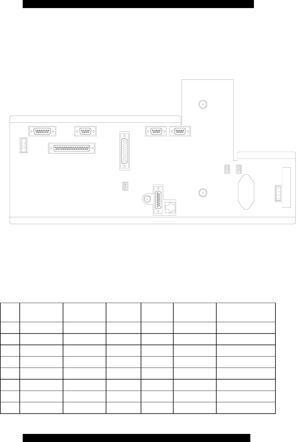
9.1.1 CE BACKPLANE
The G2BT Control Equipment Backplane has the I/O connections for the CE chassis. The
following diagram shows the location of the connectors.
J21
J23
J12 J7
J14
J13
J20
J15 J8
J17
J27
J26
J10
J22
J11
J9
G2BT CE Backplane
9.1.1.1 J7 External Controller Interface (37 Pin Female D Sub Connector)
PI
N PnP/xTIP I-20 SatRX SyLC SCM NET
NAMES CONNECTS
TO
J7
P1
SHIELD GND GND GND Backplane
J7
P2
RFC MAINT A R(A) AsyncRXD
+
AsyncRX
D+
MODEM_TX
DA
J3-P58, J16-P2, J25-P2
J7
P3
TX MAINT A T(A) AsyncTXD
+
AsyncTX
D+
MODEM_RX
DA
J3-P62, J16-P3, J25-P3
J7
P4
PT DATA A I(A) DTA+ DATA RS485_D+ J4-P37, J6-P41
J7
P5
PT FRAME A C(A) DCD+ KEY+ DIST_DCD J4-42, J6-P50
J7
P6
Wildcard out 1 Wildcard out 1 Wildcard
out 1
J7
P7
SGND GND GND GND Backplane
J7
P8
MARK A B(A) Wildcard
in 2+
BAUD MODEM_DC
DA
J3-P73, J16-P8, J25-P8

Sonik G2BT Base Transmitter User Manual
March 14, 2002 26 7M487C4
J7
P9
Wildcard out
2+
Wildcard out
2+
AsyncCTS
+
AsyncCT
S+
MODEM_CTS
A
J3-P67, J16-P5, J25-P5
J7
P1
0
Wildcard in 3 Wildcard in 3 Wildcard
in 3
J7
P1
1
TX OK+ Wildcard out
3+
AsyncDSR
+
AsyncDS
R+
MODEM_DSR
A
J3-P69, J16-P6, J25-P6
J7
P1
2
Wildcard in 4 Wildcard in 4 Wildcard
in 4
J7
P1
3
J7
P1
4
RFC MAINT B R(B) AsyncRXD
-
AsyncRX
D-
MODEM_TX
DB
J3-P12, J16-P14, J25-
P14
J7
P1
5
Wildcard in 6 Wildcard in 6 Wildcard
in 6
J7
P1
6
TX MAINT B T(B) AsyncTXD
-
AsyncTX
D-
MODEM_RX
DB
J3-P10, J16-P16, J25-
P16
J7
P1
7
PT CLOCK A S(A) CLK+ CLK RS485_CLK+ J4-P39, J6-P51
J7
P1
8
Wildcard in 7 Wildcard in 7 Wildcard
in 7
J7
P1
9
GND GND GND GND Backplane
J7
P2
0
RFC REQ+ Wildcard in 8+ AsyncDTR
+
AsyncDT
R+
MODEM_DTR
A
J3-P71, J16-P20, J25-
P20
J7
P2
1
Wildcard in 9+ Wildcard in 9+ AsyncRTS
+
AsyncRT
S+
MODEM_RTS
A
J3-P66, J16-P4, J25-P4
J7
P2
2
PT DATA B I(B) DTA- Data- RS485_D- J4-P36, J6-P42
J7
P2
3
Wildcard in 10 Wildcard in 10 Wildcard
in 10
J7
P2
4
PT FRAME B C(B) DCD- KEY- DIST_DCDB J4-P45
J7
P2
5
Wildcard in 9- Wildcard in 9- AsyncRTS
-
AsyncRT
S-
MODEM_RTS
B
J3-P14, J16-P19, J25-
P19
J7
P2
6
MARK B B(B) Wildcard
in 2-
Wildcard
in 2-
MODEM_DC
DB
J3-P4, J16-P10, J25-
P10
J7
P2
7
Wildcard out 2- Wildcard out 2- AsyncCTS
-
AsyncCT
S-
MODEM_CTS
B
J4-P70, J16-P13, J25-
P13
J7
P2
8
Wildcard out 4 Wildcard out 4 Wildcard
out 4
J7
P2
9
TX OK- Wildcard out 3- AsyncDSR
-
AsyncDS
R-
MODEM_RI J25-P22,J8-P22
J7
P3
0
RFC REQ- Wildcard in 8- AsyncDTR
-
AsyncDT
R-
MODEM_DTR
B
J3-P16, J16-P23, J25-
P23
J7
P3
1

Sonik G2BT Base Transmitter User Manual
March 14, 2002 27 7M487C4
J7
P3
2
Wildcard out 5 Wildcard out 5 Wildcard
out 5
J7
P3
3
Wildcard out 6 Wildcard out 6 Wildcard
out 6
9.1.1.2 J7 External ControllerInterface (37 Pin Female D Sub Connector)
P
I
N
PnP/xTIP I-20 SatRX SyLC SCM NET
NAMES CONN
ECTS
TO
J7
P3
4
Wildcard out
7
Wildcard out
7
Wildcard
out 7
J7
P3
5
PT CLOCK
B
S(B) CLK- CLK- RS485_CLK- J4-P40,
J6-P52
J7
P3
6
Wildcard out
8
Wildcard out
8
Wildcard
out 8
J7
P3
7
Wildcard out
9
Wildcard out
9
Wildcard
out 9
9.1.1.3 J8 CSU/DSU Interface (25 Pin Male D Sub Connector)
PIN FUNCTIO
N DIRECTI
ON
J16P1 GND To Backplane Backplane
J16P2 MODEM_TXD
A
From
Backplane
J3-P58, J7-P2, J25-P2 MODEM_TXDA
J16P3 MODEM_RXD
A
To Backplane J3-P62, J7-P3, J25-P2 MODEM_RXDA
J16P4 MODEM_RTS
A
From
Backplane
J3-P66, J7-P21, J25-P4 MODEM_RTSA
J16P5 MODEM_CTS
A
To Backplane J3-P67, J7-P9, J25-P5 MODEM_CTSA
J16P6 MODEM_DSR
A
To Backplane J3-P69, J7-P11, J25-P6 MODEM_DSRA
J16P7 GND To Backplane Backplane
J16P8 MODEM_DCD
A
To Backplane J3-P73, J7-P8, J25-P8 MODEM_DCDA
J16P9 MODEM_RXC
B
To Backplane J4-P33, J25-P9 MODEM_RXCB
J16P10 MODEM_DCD
B
To Backplane J3-P4, J7-P26, J25-P10 MODEM_DCDB

Sonik G2BT Base Transmitter User Manual
March 14, 2002 28 7M487C4
B
J16P11 MODEM_SCT
EB
From
Backplane
J3-P3, J25-P11 MODEM_SCTEB
J16P12 MODEM_TXC
B
To Backplane J4-P34, J25-P12 MODEM_TXCB
J16P13 MODEM_CTS
B
To Backplane J4-P70, J7-P27, J25-P13 MODEM_CTSB
J16P14 MODEM_TXD
B
From
Backplane
J3-P12, J7-P14, J25-P14 MODEM_TXDB
J16P15 MODEM_TXC
A
To Backplane J3-P60, J25-P15 MODEM_TXCA
J16P16 MODEM_RXD
B
To Backplane J3-P10, J7-P16, J25-P16 MODEM_RXDB
J16P17 MODEM_RXC
A
To Backplane J3-P18, J25-P17 MODEM_RXCA
J16P18 MODEM_LL To Backplane J3-P75, J7-P29, J25-P18 MODEM_LL
J16P19 MODEM_RTS
B
From
Backplane
J3-P14, J7-P25, J25-P19 MODEM_RTSB
J16P20 MODEM_DTR
A
From
Backplane
J3-P71, J7-P20, J25-P20 MODEM_DTRA
J16P21 MODEM_RL From
Backplane
J3-P6, J25-P21 MODEM_RL
J16P22 MODEM_RI To Backplane J3-P20, J25-P22 MODEM_RI
J16P23 MODEM_DTR
B
From
Backplane
J3-P16, J7-P30, J25-P23 MODEM_DTRB
J16P24 MODEM_SCT
EA
From
Backplane
J3-P64, J25-P24 MODEM_SCTEA
J16P25 MODEM_TM To Backplane J3-P8, J25-P25 MODEM_TM
9.1.1.4 J9 Backup Battery (4 Pin Male Snap and Lock Connector)
PIN FUNCTION DIRECTION CONNECTS TO
J9P1 +28VDC To Backplane J1P4-15
J9P2 GND To Backplane Backplane
J9P3 B+ To Backplane J1P54, J1P55
J9P4 B- To Backplane J1P56, J1P57
9.1.1.5 J10 Aux +5 Vdc (3 Pin Male Snap and Lock Connector)
PIN FUNCTION DIRECTION CONNECTS TO
J10P1 +5VDC From Backplane J1P24-31
J10P2 Not used

Sonik G2BT Base Transmitter User Manual
March 14, 2002 29 7M487C4
J10P3 GND To Backplane Backplane
9.1.1.6 J11 Aux +14 Vdc Interface (3 Pin Male Snap and Lock Connector)
PIN FUNCTION DIRECTION CONNECTS TO
J11P1 +14VDC From Backplane J1P16-23
J11P2 GND To Backplane Backplane
J11P3 GND To Backplane Backplane
9.1.1.7 J12 External Power Interface (10 Pin Male Snap and Lock
Connector)
PIN FUNCTION DIRECTION CONNECTS TO
J12P1 GND To Backplane Backplane
J12P2 GND To Backplane Backplane
J12P3 +5 Vdc From Backplane J1P24-31
J12P4 +5 Vdc From Backplane J1P24-31
J12P5 +14 Vdc From Backplane J1P16-23
J12P6 +14 Vdc From Backplane J1P16-23
J12P7 +28 Vdc From Backplane J1P4-15
J12P8 GND To Backplane Backplane
J12P9 +28 Vdc From Backplane J1P4-15
J12P10 GND To Backplane Backplane
9.1.1.8 J13 10 MHz Ref. (BNC FEMALE)
PIN FUNCTION DIRECTION CONNECTS TO
J13
OTR
CON
GND To Backplane Backplane
J13
Center
10 MHz Ref To Backpane J4P56
9.1.1.9 J14 GPS Sharing Interface ( 15 Pin Female D Sub Connector)
PIN FUNCTION DIRECTION CONNECTS TO

Sonik G2BT Base Transmitter User Manual
March 14, 2002 30 7M487C4
J14P1 Not used
J14P2 Not used
J14P3 Not used
J14P4 Not used
J14P5 GPS_RX+ From Backplane J5-P5
J14P6 GPS_1PPS+ From Backplane J5-P7
J14P7 GPS_RDY From Backplane J5-P10
J14P8 GND From Backplane
J14P9 GND From Backplane
J14P10 GND From Backplane
J14P11 GND From Backplane
J14P12 Not Used
J14P13 GPS_RX- From Backplane J5-P6
J14P14 GPS_1PPS- From Backplane J5-P8
J14P15 GPS_MSTR_SEL From Backplane J5-P9
9.1.1.10 J15 Debug Interface (9 Pin Female D Sub Connector)
PI
N FUNCTI
ON DIRECTI
ON Default Function CONNEC
TS TO
J15P
1
GND To Backplane Ground connection Backplane
J15P
2
DAC1 To Backplane Sub Channel 0 baseband J3P13
J15P
3
DAC3 To Backplane Composite Q waveform J3P31
J15P
4
DIG1 To Backplane GPS 1PPS J3P17
J15P
5
DIG3 To Backplane IO Strobe J3P21
J15P
6
DAC0 To Backplane Sub Channel 0 I waveform J3P11
J15P
7
DAC2 To Backplane Composite I waveform J3P32
J15P
8
DIG0 To Backplane Frame Pulse J3P15
J15P
9
DIG2 To Backplane Sync window J3P19

Sonik G2BT Base Transmitter User Manual
March 14, 2002 31 7M487C4
9.1.1.11 J17 Telco Interface (8 Conductor Modular Keyed Socket)
PIN FUNCTION DIRECTION CONNECTS TO
J24P1 SIG1 Programmable J25P73
J24P2 SIG2 Programmable J25P74
J24P3 SIG3 Programmable J25P75
J24P4 SIG4 Programmable J25P76
J24P5 SIG5 Programmable J25P77
J24P6 SIG6 Programmable J25P78
J24P7 SIG7 Programmable J25P79
J24P8 SIG8 Programmable J25P80
9.1.1.12 J20 Door Alarm Interface (3 Pin Male Snap and Lock
Connector)
PIN FUNCTION DIRECTION CONNECTS TO
J20P1 GND Backplane
J20P2 DOOR_ALM To Backplane J4-P25
J20P3 GND Backplane
9.1.1.13 J21 PA SPI Interface (15 Pin Female D Sub Connector)
PIN FUNCTION DIRECTION CONNECTS TO
J17P1 GND To Backplane Backplane
J17P2 PA_SPI_A5 From Backplane J4-P65
J17P3 PA_SPI_A4 From Backplane J4-P66
J17P4 PA_SPI_A3 From Backplane J4-P67
J17P5 PA_SPI_A2 From Backplane J4-P68
J17P6 PA_SPI_A1 From Backplane J4-P64
J17P7 PA_SPI_A0 From Backplane J4-P63
J17P8 PA_SPI_CLK From Backplane J4-P77
J17P9 PA_SPI_MOSI From Backplane J4-P78
J17P10 PA_SPI_MISO To Backplane J4-P75
J17P11 Not used
J17P12 Not used
J17P13 Not used
J17P14 Not used

Sonik G2BT Base Transmitter User Manual
March 14, 2002 32 7M487C4
J17P15 Not used
9.1.1.14 J22 Internal Detector Interface (9 Pin Female D Sub Connector)
PIN FUNCTION DIRECTION CONNECTS TO
J18P1 VREF1 To Backplane J2RCP8
J18P2 +28 Vdc From Backplane Backplane
J18P3 GND To Backplane Backplane
J18P4 GND To Backplane Backplane
J18P5 VFWD1 To Backplane J2RCP7
J18P6 SHIELD_GND To Backplane Backplane
J18P7 Not used
J18P8 Not used
J18P9 Not used
9.1.1.15 J23 Remote Detector Interface (9 Pin Female D Sub Connector)
PIN FUNCTION DIRECTION CONNECTS TO
J19P1 VREF2 To Backplane J2RCP16
J19P2 +28 Vdc From Backplane
J19P3 GND Backplane
J19P4 GND Backplane
J19P5 VFWD2 To Backplane J2RCP14
J19P6 SHIELD GND Backplane
J19P7 Not used
J19P8 Not used
J19P9 Not used
9.1.1.16 J26 Exciter RF Feedback (Female SMA)
PIN FUNCTION DIRECTIO
N CONNECTS TO
J21 CTR
CON
RF_FEEDBACK_IN To Backplane Exciter CCA
J21 OTR
CON
GND To Backplane Backplane

Sonik G2BT Base Transmitter User Manual
March 14, 2002 33 7M487C4
9.1.1.17 J27 Exciter RF Out (Female SMA)
PIN FUNCTION DIRECTIO
N CONNECTS TO
J22 CTR
CON
RF_OUT From Backplane To Splitter
J22 OTR
CON
GND To Backplane Backplane
9.1.1.18 Backplane Mating Connector Table
Connection Description Manufacturer MFR P/N
J7 37 Pin Male D sub
J8 25 Pin Female D sub
J9 4 Pin Snap and Lock Molex WM5864-ND
J10 Connector 3 Pin/Contact
Mod IV
AMP/Tyco
Electronics
102241-1, 1-
87523-9
J11 Connector 3 Pin/Contact
Mod IV
AMP/Tyco
Electronics
102241-1, 1-
87523-9
J12 10 Pin Male Snap and
Lock
Adamtech FCS-10-SG
J13 BNC(m)
J14 15 Pin Male D sub
J15 9 Pin Male D sub
J17 RJ45 Male
J20 Connector 3 Pin/Contact
Mod IV
AMP/Tyco
Electronics
102241-1, 1-
87523-9
J21 Connector 3 Pin/Contact
Mod IV
AMP/Tyco
Electronics
102241-1, 1-
87523-9
J22 9 Pin Male D sub
J23 9 Pin Male D sub
J26 SMA(m)
J27 SMA(m)

Sonik G2BT Base Transmitter User Manual
March 14, 2002 34 7M487C4
9
9
9.
.
.2
2
2
C
C
CE
E
E
P
P
PO
O
OW
W
WE
E
ER
R
R
S
S
SU
U
UP
P
PP
P
PL
L
LY
Y
Y
The control chassis power supply has been designed by Mesa Power Systems. It has its own AC
power supply with provision battery-back-up for up to 15 minutes of operation. Internally, it uses
an off-the-shelf AC-DC switching power converter. A simple micro-controller monitors the AC
supply, battery voltage and current, and battery charging. It communicates this status information
to the CPU via the SPI bus.
The back-up battery powers the control chassis, and does not power the RF power amplifiers, so
no RF output will be produced when operating off of the internal back-up supply. The internal
network interface will continue to operate off of the back-up supply.

Sonik G2BT Base Transmitter User Manual
March 14, 2002 35 7M487C4
10 USER INTERFACES
1
1
10
0
0.
.
.1
1
1
C
C
CO
O
OM
M
MM
M
MA
A
AN
N
ND
D
D
L
L
LI
I
IN
N
NE
E
E
E
E
ED
D
DI
I
IT
T
TO
O
OR
R
R
The command line editor accumulates keystrokes from user input into a command line to be
passed to a command line interpreter (CLI) then displays the results of the command. The
editor interacts with the operator allowing characters in the command to be inserted and
deleted before it is submitted to the CLI. A history buffer is maintained for each operator
session containing the previous 20 commands that can be recalled, edited, and resubmitted to
the CLI using the arrow keys.
If current session is logged on as the system administrator or the administrator is not logged
on and the current session is with the front panel console port, the command line editor will
also output the system console messages in-between operator input.
1
1
10
0
0.
.
.2
2
2
C
C
CO
O
ON
N
NS
S
SO
O
OL
L
LE
E
E
The front panel serial port, or Console, is managed by a Telnet “translator” task. In its idle
state, the console manager outputs the console messages out the serial port. When an
operator strikes a key the console manager initiates an internal Telnet session and simply
passes characters between the serial port and the TCP/IP socket. This relieves the rest of the
operator interface code from having to support user I/O coming from multiple places and
requiring separate decisions and API calls for all input and output.
Once a user session is initiated on the console port the console messages are no longer
displayed by this task because the command line editor then assumes this responsibility until
the session is exited. Console message output will also be yielded while the system
administrator is currently logged on through Telnet.
1
1
10
0
0.
.
.3
3
3
T
T
TE
E
EL
L
LN
N
NE
E
ET
T
T
A
A
AN
N
ND
D
D
C
C
CO
O
ON
N
NS
S
SO
O
OL
L
LE
E
E
P
P
PO
O
OR
R
RT
T
T
U
U
US
S
SE
E
ER
R
R
I
I
IN
N
NT
T
TE
E
ER
R
RF
F
FA
A
AC
C
CE
E
E
The user interface is presented at the control module’s front panel serial port or when the
system is accessed remotely using the Telnet protocol.
The uses interface allows for reading and modifying configuration parameters as well as
launching calibration, test and reset processes.
There are four levels of access in the user interface:

Sonik G2BT Base Transmitter User Manual
March 14, 2002 36 7M487C4
• Admin all display/set commands
• Oper1 all display commands, all set commands except critical system settings
• Oper2 all display commands, some set commands
• Oper3 all display commands, no set commands

Sonik G2BT Base Transmitter User Manual
March 14, 2002 37 7M487C4
11 SW DOWNLOAD PROCESS
There are three phases in the software download process:
1. Receive the software download file.
2. Write the software download file into Flash memory.
3. Cutover to the new version of downloaded software.
1
1
11
1
1.
.
.1
1
1
R
R
RE
E
EC
C
CE
E
EI
I
IV
V
VE
E
E
S
S
SO
O
OF
F
FT
T
TW
W
WA
A
AR
R
RE
E
E
D
D
DO
O
OW
W
WN
N
NL
L
LO
O
OA
A
AD
D
D
F
F
FI
I
IL
L
LE
E
E
The software download file is transferred to the G2BT Station remotely through the LAN
using TFTP, or locally through the front panel serial port using Xmodem or Ymodem
protocols. When one of the methods has been activated but not yet completed, the other
method handling is disabled (any data received using that protocol is ignored).
• TFTP (Trivial File Transfer Protocol)
The transmitter functions as a TFTP client; in this mode, the software download file will
be “pulled” or downloaded by the station from a predefined server. The server IP address,
download date, time and file name is specified through the user interface or through SNMP
MIB sets.
During download, the system keeps information on the number of packets that have been
transferred with or without success and the number of packets that have been transferred with
success. There are also user specified values to control the timeout value from packet ack/err
sent and the next packet received, number of retries that the station will send packet err to the
server before aborting the session and interval from when the station receives a data packet to
when it sends a packet ack/err.
• Front Panel Serial Port
The software download file can be transferred locally using the serial port and specifying the
Xmodem or Ymodem protocols through the serial program (typically Hyperterminal or
ProComm).
1
1
11
1
1.
.
.2
2
2
W
W
WR
R
RI
I
IT
T
TE
E
E
S
S
SO
O
OF
F
FT
T
TW
W
WA
A
AR
R
RE
E
E
D
D
DO
O
OW
W
WN
N
NL
L
LO
O
OA
A
AD
D
D
F
F
FI
I
IL
L
LE
E
E
I
I
IN
N
NT
T
TO
O
O
F
F
FL
L
LA
A
AS
S
SH
H
H
M
M
ME
E
EM
M
MO
O
OR
R
RY
Y
Y
The software download file always contains all binary images for the SCM software, the DSP
software and the FPGA configuration code.

Sonik G2BT Base Transmitter User Manual
March 14, 2002 38 7M487C4
The G2BT contains Flash memory to store two complete images of the software download
file (i.e. two complete images of each of the binary images for the SCM software, the DSP
software and the FPGA configuration code). One virtual Flash memory bank contains a copy
of the currently active software images, the other virtual Flash memory bank contains a copy
of a dormant set of binary images. The SCM controls this information by storing several
small arrays of software download status in the EEPROM.
The arrays in EEPROM contain the following information:
• FlashBank[active, dormant] = virtual bank 1 | virtual bank 2
• Version[active | dormant ] [SCM | DSP | FPGA | Loader | Revert] = version
The software download file is decoded, verified for platform and data integrity and then
written to the dormant virtual Flash memory bank. The Version[dormant][] array is updated
with the version values of the SCM, DSP and FPGA binary images as written in the software
download file.
1
1
11
1
1.
.
.3
3
3
C
C
CU
U
UT
T
TO
O
OV
V
VE
E
ER
R
R
T
T
TO
O
O
T
T
TH
H
HE
E
E
N
N
NE
E
EW
W
W
V
V
VE
E
ER
R
RS
S
SI
I
IO
O
ON
N
N
O
O
OF
F
F
D
D
DO
O
OW
W
WN
N
NL
L
LO
O
OA
A
AD
D
DE
E
ED
D
D
S
S
SO
O
OF
F
FT
T
TW
W
WA
A
AR
R
RE
E
E
The software binaries remain in the Flash memory as dormant until actively specified to be
cutover.
First the user specifies which version to cutover to through the user interface or through
SNMP MIB sets. The system verifies that these are valid versions. If valid, the SCM updates
the arrays in EEPROM to reflect the user specified versions. The actual cutover does not yet
occur.
Then the user activates the cutover process through the user interface or through SNMP MIB
sets. The activation can be NOW or TIMED (scheduled) depending on command parameters.
The system verifies that the specified cutover version(s) is different from the current active
version. This prevents unnecessary cutovers. If the cutover version(s) is different from the
active current version, the system disables paging, turns off all interrupts thereby halting all
network and front panel activity, and performs a warm CPU reset.
At reset, the boot loader loads the active SCM software into RAM and begins execution. The
SCM software sends the active FPGA configuration code to the FPGA and the active DSP
code to the DSP.

Sonik G2BT Base Transmitter User Manual
March 14, 2002 39 7M487C4
12 POWER CONTROL
1
1
12
2
2.
.
.1
1
1
I
I
IN
N
NT
T
TR
R
RO
O
OD
D
DU
U
UC
C
CT
T
TI
I
IO
O
ON
N
N
The power control function is designed to control keying and dekeying of the RF transmitter,
monitor the functionality and integrity of the exciter, power amplifiers, and the PA power
supplies, and operate the control loop that maintains the RF power output at the desired level.
1
1
12
2
2.
.
.2
2
2
C
C
CO
O
ON
N
NF
F
FI
I
IG
G
GU
U
UR
R
RA
A
AT
T
TI
I
IO
O
ON
N
N
M
M
MO
O
ON
N
NI
I
IT
T
TO
O
OR
R
RI
I
IN
N
NG
G
G
The station power control and power output equipment is periodically monitored to ensure a safe
shutdown or cutback to a lower output power. The monitoring rate is every 100 mS. The RF
amplifiers themselves will not output power into an open load for more than about 100mS.
The user interface variable pa installed should be set to the number of power amplifiers present.
If 4 are present, the desired output power may be set to 400W, if 1 is present, the output power
may not exceed 100W. If 4 are present, but 1 or more cannot be operated, the output power will
be automatically reduced as detailed in the power cutback and transmitter de-key section below.
The number of available PAs can be determined from the internal monitoring functions of the
PAs, which allow supply voltage, supply current, temperature, fan status, and power output be
measured. In the event of a problem, the gain of the PA can be reduced, or it can be shut down
entirely.
The exciter card is monitored to determine that the IF and RF synthesizer LOs are operating and
locked.
The integrity of the system output devices and cabling is determined by measuring forward and
reflected power at the 4 PA internal wattmeters and the system wattmeter.
1
1
12
2
2.
.
.3
3
3
P
P
PO
O
OW
W
WE
E
ER
R
R
C
C
CO
O
ON
N
NT
T
TR
R
RO
O
OL
L
L
A
A
AL
L
LG
G
GO
O
OR
R
RI
I
IT
T
TH
H
HM
M
M
The G2BT can be configured as either a high power station, transmitting a maximum of 400 watts
when fitted with 4 PAs, or as a low-power station transmitting a maximum of 100 watts when
configured with 1 PA. The desired power level may be selected by the user in the range 100W to
400W for the high power station, and 25W to 100W for the low power station. The station may
also cut back the output power as a response to fault conditions such as overheating.

Sonik G2BT Base Transmitter User Manual
March 14, 2002 40 7M487C4
The power reporting and control system take into account the number of carriers being
transmitted at any one time. The power setting and reporting value is the total station RF output
power, in watts. For example, if there are 4 carriers enabled, and the user sets the station power
to 400 watts, each carrier will be controlled to 100 watts. When the station is transmitting, it will
report 400 watts as being full power.
If the station is configured for 4 carriers, and the transmit data feed only tells the station to use
one of the carriers, the power output will be reported as 100 watts. If some or all of the
subcarriers dekey before the end of the frame, the power will be reported as if the carriers had
been transmitting for the entire frame. The power control algorithm takes into account the number
of carriers on the air at any instant, and normalizes that to the power output relative to the
maximum number of carriers that the station is configured to use. For example, if the station is
set up for 400W with 3 carriers enabled, each carrier will radiate 133W. The reported output
power when only 2 subchannels are active will be 267W.
1
1
12
2
2.
.
.4
4
4
P
P
PO
O
OW
W
WE
E
ER
R
R
C
C
CU
U
UT
T
TB
B
BA
A
AC
C
CK
K
K
A
A
AN
N
ND
D
D
S
S
SH
H
HU
U
UT
T
TD
D
DO
O
OW
W
WN
N
N
Power cutback is carried out when an operational failure is detected by the configuration monitor
task. The system may cut back by 1dB or 3dB, or may de-key the transmitter. An alarm and error
log entry is generated for all cutback and de-key events.
The following events trigger cutbacks and de-keying of the transmitter:

Sonik G2BT Base Transmitter User Manual
March 14, 2002 41 7M487C4
Cutback by 1 dB Cutback by 3 dB Station de-keys
VSWR at 1 PA RF output
connector > 3:1 VSWR at 1 PA RF output
connector > 10:1 VSWR at more than 1 PA
RF output connector >
10:1
VSWR at antenna
connector > 3:1 VSWR at antenna
connector > 10:1
Temperature of station
exceeds 65˚C Temperature of station
exceeds 70˚C Temperature of station
exceeds 80˚C
One or more PAs issue a
temperature warning 1 PA or 1 PSU fails
internally in a 400W
station
More than 1 PA and/or
PSU fails internally in a
400W station
The PA and/or PSU fails
internally in a 100W
station
Clipping of RF waveform
detected (FCC rules)
Exciter card loses lock
Cartesian feedback loop
fails or is disconnected
RF output power at
antenna connector
exceeds set power level
by 10%
Table 1, Power Cutback Conditions
If a cutback occurs due to a fault, the G2BT may revert to full power if the fault goes away for 60
seconds.
If a de-key occurs, the station will set the transmission paging mode user interface variable (tran
pa) to OFF, and the calibration test mode variable (cal t) to STOP, and will not allow
transmission even after cycling power until the paging mode variable is locally or remotely set to
ON, or the calibration test mode variable is locally or remotely set to START.

Sonik G2BT Base Transmitter User Manual
March 14, 2002 42 7M487C4
13 COMMAND LINE USER INTERFACE
The command line interface is a password-protected English language command interpreter. The
command structure is based on a hierarchy of parameter mnemonics that can be displayed or
modified and additional commands that can activate subprograms, which may display reports,
such as the “ping” command, or run interactively, such as the “menu” command. Subsets of
parameters can be displayed by entering partial commands and the output of such long reports is
then processed by a filter similar to the “more” utility on Unix system or the “/p” option on many
MS-DOS commands.
Wherever logical, the hierarchy and mnemonics of parameters mirror the SNMP MIB structure.
A command line editor maintains a history of the previous 20 commands entered which can be
recalled using the up and down arrow keys. Any single command line can be edited using the
right, left, backspace and delete keys or canceled using the escape key.
1
1
13
3
3.
.
.1
1
1
C
C
CO
O
ON
N
NV
V
VE
E
EN
N
NT
T
TI
I
IO
O
ON
N
NS
S
S
Convention Description
[brackets] Indicates an optional item in a syntax statement. Only type the
optional item, not the brackets themselves.
| Stands for “or” and separates items that you must select one or
the other of.
<key> Refers to a single key on the keyboard. For example, <F1> refers
to the key labeled “F1” on your keyboard.
UPPERCASE Indicates the actual commands, words, or characters that you
must type. Only the upper-case underlined characters must be
typed. Lower case characters are optional.
Italic Provides a placeholder for information that you must type.
<Tab> TAB key and VT100 arrow keys can be used for moving around
between fields in forms and viewing statistics in menu system.
Also <ESC> cancels the field edit or returns to previous menu.
Command Line
Editor Supports “editing” of command lines. <Left>, <Right>, <Home>,
<End>, <Insert>, <Delete>, and <Backspace> gives the user more
flexibility.
Oper1, Oper2 Indicates what user level is support for each command . Note:
Admin has display/set access to all commands, Oper3 has display
only access to all commands so these user levels are not indicated.

Sonik G2BT Base Transmitter User Manual
March 14, 2002 43 7M487C4
1
1
13
3
3.
.
.2
2
2
C
C
CO
O
OM
M
MM
M
MA
A
AN
N
ND
D
D
L
L
LI
I
IS
S
ST
T
T
13.2.1 ALARM...
There are a number of alarm events which operate and can be configured independently. Each
alarm event alarmName is managed by the following sub-commands. See Section “Alarms and
Management” for alarm management and conditions.
Oper1 Alarm [alarmName] Enable [ YES | NO ]
Set or display whether this alarm is operational. This command can either enable or
disable individual alarms or, when combined with the ALL command mnemonic, can be
used to turn all alarms on or off with the single command ALARM ALL ENABLE NO
or ALARM ALL ENABLE YES.
Oper1 Alarm [alarmName] SEverity [ OFF | INFO | MINOR | MAJOR | CRITICAL ]
Set or display the alarm’s severity. When the alarm severity is set to OFF the alarm event
is disabled, regardless of the ALARM alarmName ENABLE setting. Generation of
SNMP trap messages is also controlled by the THRESHOLD TRAPLEVEL setting. Trap
messages will only be sent if the configured severity is greater than or equal to the
threshold level.
Oper1 Oper2 Alarm [alarmName] STATUs [ SET | CLEAR ]
Set or display the current status of the alarm. Using this command an alarm can be
cleared, or set, by the operator by setting this value but the normal functioning of an
alarm event will not occur. If an alarm is manually set or cleared by the operator the
system may, depending on the alarm, change its status. That is to say manually changing
the alarm’s status is not “permanent” and does not override the system’s manipulation of
the alarm.
Oper1 Alarm [alarmName] Manual [ SET | CLEAR ]
Manually set or clear an alarm. Setting or clearing and alarm using this command will
also trigger normal alarm functioning. That is to say, trap messages, console message, or
log entries will be generated, depending on the alarm’s configuration, when this
command is used.
Alarm [alarmName] STATS Set Timestamp
Display the timestamp of the last time this alarm event occurred as YYYY/MM/DD
HH:MM:SS.
Alarm [alarmName] STATS Set Count
Display the number of times this alarm condition occurred since the last system startup.
Alarm [alarmName] STATS Clear Timestamp
Display the timestamp of the last time this alarm event was cleared as YYYY/MM/DD
HH:MM:SS.
Alarm [alarmName] STATS Clear Count
Display the number of times this alarm condition was cleared since the last system
startup.

Sonik G2BT Base Transmitter User Manual
March 14, 2002 44 7M487C4
Oper1 Oper2 Alarm [alarmName] COnsole Enable [ YES | NO ]
Set or display whether to print a message on the console when this alarm status
changes.
Oper1 Oper2 Alarm [alarmName] COnsole Interval [ 0...4294967295 ]
Set or display how often, in seconds, to redisplay a console message while the alarm
status is SET. Setting this value to zero disables repeating of the alarm message. Setting
this value to 60, for example, will cause a console message to be printed every 60
seconds informing the operator of the alarm until it’s status changes to CLEAR. If
console messages are not enabled this setting has no effect.
Oper1 Alarm [alarmName] Trapmsg Enable [ YES | NO ]
Set or display whether to send SNMP trap message when this alarm status changes. If this
value is set to YES an SNMP trap message will be sent to all defined SNMP destinations
(see SNMP [1..5] command). The THRESHOLD TRAPLEVEL and ALARM
alarmName SEVERITY settings also controls transmission of SNMP trap messages.
Oper1 Alarm [alarmName] Trapmsg Interval [ 0…60 ]
Set or display how often, in seconds, to retransmit an SNMP trap message while the
alarm status is SET. Setting this value to zero disables repeating SNMP trap messages.
Setting this value to 60, for example, will cause an SNMP trap message to be transmitted
every 60 seconds until it’s status changes to CLEAR. If SNMP trap messages are not
enabled this setting has no effect. The THRESHOLD TRAPLEVEL and ALARM
alarmName SEVERITY settings also controls transmission of SNMP trap messages.
Oper1 Oper2 Alarm [alarmName] Log Set [ YES | NO ]
Set or display whether an entry will be written to the alarm log when this alarm status
transitions from CLEAR to SET. If the alarm is not enabled, or the severity is set to OFF,
or if Log is set to NO, no log entry will be generated.
Oper1 Oper2 Alarm [alarmName] Log Clear [ YES | NO ]
Set or display whether an entry will be written to the alarm log when this alarm status
transitions from SET to CLEAR. If the alarm is not enabled, or the severity is set to OFF,
or the Log Clear is set to NO, no log entry will be generated.
13.2.2 CALIBRATION...
The following are the commands relating to station calibration.
Oper1 CAlibration Subchan [ 1…4 ] Pattern [ Disable | SymA | SymB | SymC | SymD |
BigComma | LittleComma | Staircase | PseudoRandom | ReFLEX50 |
Magellan1/4R25 | Magellan1/2R25 | Magellan3/4R25 | Carrier ]
Set or display the pattern used for calibration and test for the specified subchannel
Oper1 CAlibration Framerate [ 0…128 ]
Set or display the frame rate used for calibration and test. Note that a frame rate of 0
implies a single frame, 1 implies every frame, 2 implies every other frame, 3 implies
every 3rd frame, …
Oper1 CAlibration Subchan [ 1…4 ] FWdblocks [ 0…11 ]

Sonik G2BT Base Transmitter User Manual
March 14, 2002 45 7M487C4
Set or display the forward channel block count used for calibration and test for the
specified subchannel.
Oper1 CAlibration Testmode [ START | STOP ]
Set or display the calibration and test mode status. NOTE: The set command will only
take effect if the transmitter has been set in local or remote transmission mode. Refer to
command TRANSmission TXMode described below.
13.2.3 CLOCK...
The following are the commands relating to the station console port settings.
Oper1 Oper2 CLock Date [ YYYY/MM/DD ]
Display the current system clock date as “YYYY/MM/DD”. The system clock is read at
startup from the on board battery backed up RTC. The RTC and system date/time are
updated when:
• The operator manually changes the date or time.
• When GPS data is received indicating valid date/time data that is more than 1 second
different than the current system date/time.
Oper1 Oper2 CLock Time [ HH:MM:SS ]
Display the current system clock time of day as “HH:MM:SS”. “. The system clock is
read at startup from the on board battery backed up Real-Time-Clock (RTC). The RTC
and system date/time are updated when-
• The operator manually changes the date or time.
• When GPS data is received indicating valid date/time data that is more than 1 second
different than the current system date/time.
CLock Uptime
Display the time the system has been running since the last reboot as “DAYS
HH:MM:SS”. It is initialized to zero at startup and continually increments.
CLock Operation
Display the time the system has been operational as “DAYS HH:MM:SS”.
CLock Reflex Cycle
Display the current ReFLEX cycle number.
CLock Reflex Frame
Display the current ReFLEX frame number.
CLock Reflex State
Display the current ReFLEX frame state. The returned value will be MISSING,
RECEIVED (MDP packet received) or LAUNCHED (frame sent to DSP).
13.2.4 CONSOLE...
The following are the commands relating to the station console port settings.
Oper1 Oper2 COnsole Timeout [ 0...4294967295 ]

Sonik G2BT Base Transmitter User Manual
March 14, 2002 46 7M487C4
Set or display the console port user interface inactivity timeout period in seconds. Setting
this value to zero disables the session inactivity timeout function. Any other setting will
abort user sessions after the configured number of seconds expires with no input from the
user.
Oper1 Oper2 COnsole Baud [ 300 | 600 | 1200 | 2400 | 4800 | 9600 | 19200 | 38400 | 57600 | 115200
]
Set or display the baud rate operating on the front panel RS-232 serial console port.
Oper1 Oper2 COnsole Databits [ 7 | 8 ]
Set or display the number of data bits per asynchronous symbol transmitted and received
on the front panel RS-232 serial console port.
Oper1 Oper2 COnsole Stopbits [ 1 | 2 ]
Set or display the number of framing stop bits per asynchronous symbol transmitted and
received on the front panel RS-232 serial console port.
Oper1 Oper2 COnsole Parity [ NONE | ODD | EVEN | SPACE | MARK ]
Set or display the parity method for asynchronous symbols transmitted and received on
the front panel RS-232 serial console port.
13.2.5 CUTOVER...
The following are the commands relating to software cutover.
Oper1 CUtover Mode [ OFF | TIMED | NOW ]
Set or display the cutover mode. A value of OFF means that cutovers are disabled,
TIMED means that a cutover occurs at the below specified time (if dormant versions are
not the same as active versions), NOW means the cutover will occur immediately after a
software download occurs.
Oper1 CUtover Time [YYYY/MM/DD HH:MM:SS ]
Set or display the cutover time.
Oper1 CUtover Version [ version ]
Set or display the version to revert to in the event of cutover failure.
13.2.6 DISTRIBUTION...
The following are the commands relating to the station page data distribution settings.
Oper1 DIstribution Portselect [ ALL | SatRx | LAN ]
Set or display the distribution port selection. A value of ALL indicates that the
transmitter will accept valid MDP packets from all distribution ports. Any other setting
means that only the indicated distribution port can input MDP packets.
Oper1 DIstribution Hdlc Lowerlimitcrc [ 0…100 ]
Set or display the distribution lower hysteresis CRC limit for good HDLC frames
received. The parameter is a percentage of good HDLC frames received.
Oper1 DIstribution Hdlc Upperlimitcrc [ 0…100 ]

Sonik G2BT Base Transmitter User Manual
March 14, 2002 47 7M487C4
Set or display the distribution upper hysteresis CRC limit for good HDLC frames
received. The parameter is a percentage of good HDLC frames received.
Oper1 DIstribution Hdlc NUmcrcframes [ 0…30000 ]
Set or display the distribution HDLC frames CRC error measurement. The parameter is
the computational interval in frames.
Oper1 DIstribution Hdlc NEtzone 1 [ 0…65536 ]
Set or display the distribution network zone address 1.
Oper1 DIstribution Hdlc NEtzone 2 [ 0…65536 ]
Set or display the distribution network zone address 2.
Oper1 DIstribution Hdlc NEtzone 3 [ 0…65536 ]
Set or display the distribution network zone address 3.
Oper1 DIstribution Hdlc NEtzone 4 [ 0…65536 ]
Set or display the distribution network zone address 4.
Oper1 DIstribution Hdlc NEtzone Mask [ 0…65536 ]
Set or display the distribution network zone address mask.
DIstribution Satrx NETUnitaddr
Display the Satellite receiver network unit address.
DIstribution Satrx Swver
Display the Satellite Receiver SW Version.
DIstribution Satrx PRimarycarrierfreq [ 950…1450 ]
Set or display the Satellite Receiver primary carrier frequency in MHz.
DIstribution Satrx Lnbcontrolmode [ OFF | ON ]
Set or display the Satellite Receiver Low-Noise Block (LNB) mode.
DIstribution Satrx POrtsetting [ RS232 | RS485 ]
Set or display the Satellite Receiver port settings.
DIstribution Satrx Installed
Display whether the Satellite Receiver is installed. The returned value will be YES or
NO.
DIstribution Satrx Alignment Level
Display the Satellite Receiver alignment level. The returned value will be between 0 and
65536.
DIstribution Satrx Alignment Mode [ OFF | ON ]
Set or display the Satellite Receiver alignment tone mode.
13.2.7 DOWNLOAD…
The following are the commands relating to software downloads.

Sonik G2BT Base Transmitter User Manual
March 14, 2002 48 7M487C4
Oper1 DOwnload Mode [ OFF | NOW | TIMED ]
Set or display the remote software download mechanism. A value of OFF indicates
software downloads cannot be done remotely. A value of NOW will start a download
immediately. A value of TIMED indicates the station will begin making TFTP file
requests of the specified filename at the time specified to the specified server IP address.
Oper1 DOwnload SErver [ a.b.c.d ]
Set or display the TFTP Client mode server IP address in Internet dot notation.
Oper1 DOwnload File [ filename ]
Set or display the TFTP download file name.
Oper1 DOwnload TIME [ YYYY:MM:DD HH:MM:SS ]
Set or display the TFTP Client mode download date and time.
Oper1 DOwnload TIMEOut [0…4294967295 ]
Set or display the TFTP download timeout in milliseconds. This value indicates the
amount of time the station will wait after it has sent an acknowledge (or error) packet for
the next packet to arrive.
Oper1 DOwnload Interval [0…4294967295 ]
Set or display the TFTP packet interval in milliseconds. This value indicates the time
between packet receipt and packet acknowledgement.
Oper1 DOwnload Retries [0…4294967295 ]
Set or display the TFTP download retries. This value indicates the number of error
packets the station will send before it will abort the download session.
DOwnload Packets Received [ 0…4294967295 ]
Display the TFTP Client mode download packets received (successfully or not).
DOwnload Packets Programmed [ 0…4294967295 ]
Display the TFTP Client mode download packets successfully received.
Oper1 DOwnload Xmodem [filename ]
Set or display the XMODEM/YMODEM uploaded filename from the local front panel
serial port. If a filename is specified, this implies that a local file upload is being initiated.
Oper1 Oper2 DOwnload TRACe [ YES | NO ]
Set or display the software download trace status. The trace status sends out status
information to the front panel console.
13.2.8 EXCITER...
The following are the commands relating to the station exciter settings.
EXCiter Intselftest
Display the station exciter internal self-test results. The returned value will be PASS or
FAIL.
EXCiter Traininterval [ NOW | 0…60 ]

Sonik G2BT Base Transmitter User Manual
March 14, 2002 49 7M487C4
Set or display the tranlin training interval in minutes. A value of zero indicates training at
every keyup. A value of NOW indicates training will take place at the next available key
point (the set numerical value will not be altered).
13.2.9 EXIT
This command will end the user session.
13.2.10 FLASH...
The following are the commands relating to the firmware contained in flash memory.
Oper1 Flash Default
Restore the configuration to the factory default settings. NOTE: This does not
automatically save the default settings in Flash; a “FLASH SAVE” must also be entered
to achieve that.
Oper1 Flash Restore
Restore the configuration from Flash memory.
Oper1 Flash Save
Save the current configuration to Flash memory.
Flash View
Display the configuration in Flash memory.
13.2.11 GPS...
The following are the commands relating to the GPS settings.
Gps Model
Display the model of the GPS.
Gps STatus
Display the status of the GPS device driver. When no GPS is connected or the device is
not operating this command will return “NO SIGNAL”. When the GPS device is
operating but does not have adequate satellite visibility, is in power up search mode, or
cannot resolve an adequate time fix this command will return “SEARCHING”. When the
GPS device is reporting accurate timing information this command returns “GOOD”.
Gps Altitude
Displays the altitude reported by position device in meters.
Gps Dop Type
Displays the Dilution-Of-Precision type. The value will be either PDOP (3D) or HDOP
(2D).
Gps Dop Value
Displays the Dilution-Of-Precision value. This will be a number between 0 and 999, each
number representing a 0.1 resolution.
Gps LAtitude

Sonik G2BT Base Transmitter User Manual
March 14, 2002 50 7M487C4
Displays the latitude reported by position device in radians (degrees, minutes, seconds).
Gps LOngitude
Displays the longitude reported by position device in radians (degrees, minutes, seconds).
Gps SAtellite Tracked
Displays the number of tracked satellites.
Gps SAtellite Visible
Displays the number of visible satellites.
Gps SYnc
Displays the current state of the timing synchronization status. This information is the
equivalent of the Sync LED; the returned values will be “OFF” (Sync LED off),
“SEARCHING” (Sync LED red), “TRACKING” (Sync LED red), “LOCKED” (Sync
LED green) or “HOLDING” (Sync LED orange).
13.2.12 LOG…
The following are the commands relating to the Alarm logs.
Log Clear
Display the list of alarms that have been cleared.
Log Curr
Display the list of all currently active alarms.
Log HIGhest
Display the worst case active alarm condition. The return value could be CRITICAL,
MAJOR, MINOR, INFO.
Log HIStory
Display the list of all alarm history information.
Log Last
Display the last send alarm.
Log Sent
Display the number of alarms that have been sent.
13.2.13 NETWORK…
The following are the commands relating to the Ethernet LAN or Telnet settings.
Oper1 Network Gateway [ a.b.c.d ]
Set or display the IP address of the default gateway in Internet dot notation. This is the
address of the default network device to route packets through that are not immediately
addressable on the Ethernet LAN.
Oper1 Network Host [ hostname ]

Sonik G2BT Base Transmitter User Manual
March 14, 2002 51 7M487C4
Set or display the transmitter host name. The host name can be up to 16 characters.
Oper1 Network Lan Ipaddr [ a.b.c.d ]
Set or display the IP address of the Ethernet LAN link in Internet dot notation.
Oper1 Network Lan Subnet [ a.b.c.d ]
Set or display the IP address subnet mask of the Ethernet LAN interface for this device in
Internet dot notation.
Network Lan Macaddr
Display the Ethernet LAN MAC address.
Network Telnet ADMINName [ name ]
Set or display the Telnet administrator name.
Network Telnet ADMINPassword [ password ]
Set or display the Telnet administrator password.
Oper1 Network Telnet OPER1Name [ name ]
Set or display the specified Telnet operator name.
Oper1 Network Telnet OPER1Password [ password ]
Set or display the specified Telnet operator password.
Oper1 Network Telnet OPER2Name [ name ]
Set or display the specified Telnet operator name.
Oper1 Network Telnet OPER2Password [ password ]
Set or display the specified Telnet operator password.
Oper1 Network Telnet OPER3Name [ name ]
Set or display the specified Telnet operator name.
Oper1 Network Telnet OPER3Password [ password ]
Set or display the specified Telnet operator password.
Oper1 Network Telnet Idletimeout [ 0…86400]
Set or display the Telnet inactivity timeout in seconds. Setting this value to zero disables
the session inactivity timeout function. Any other setting will abort user sessions after the
configured number of seconds expires with no input from the user.
Oper1 Network Telnet Sessions
Display the number of currently active user sessions. NOTE: The number of Telnet
sessions is limited to 5, so that this parameter cannot exceed 6 (it includes the front panel
console if active). Also note that only one active “admin” session is allowed.
13.2.14 PA…
The following are the commands relating to the Power Amplifier settings.
PA Installed

Sonik G2BT Base Transmitter User Manual
March 14, 2002 52 7M487C4
Display the number of Power Amplifiers installed in the station transmitter.
PA Operational
Display the number of Power Amplifiers in the station that are currently operational.
PA [ 1…4 ] Attenlevel
Display the attenuation level of the specified Power Amplifier.
PA [1…4 ] Current
Display the DC supply current in Amps of the specified Power Amplifier.
Oper1 PA [ 1…4 ] Enable [ YES | NO ]
Set or display the state of the specified power amplifier. A YES value indicates that the
power amplifier is enabled, a NO value indicates that the power amplifier is not enabled.
PA [ 1…4 ] Fanstatus
Display the fan status of the specified Power Amplifier. The returned value will be FAIL
or OK.
PA [ 1…4 ] ONline
Display the online status of the specified Power Amplifier. The returned value will be
YES or NO.
PA [1…4] OUtputpwr
Display the output power in Watts of the specified Power Amplifier.
PA [1…4] OVerdrivestat
Display the overdrive status of the specified Power Amplifier. The returned value will be
OK, PROBLEM or FAIL.
PA [1…4 ] Rfltdpwr
Display the reflected power in Watts of the specified Power Amplifier.
PA [ 1…4 ] TEmperature
Display the temperature in degrees Celsius of the specified Power Amplifier.
PA [ 1…4 ] THermalstatus
Display the thermal status of the specified Power Amplifier. . The returned value will be
OK, PROBLEM or FAIL.
PA [1…4 ] Voltage
Display the DC supply voltage in Volts of the specified Power Amplifier.
13.2.15 PS…
PS [ 1…4 ] Acsense
Display the AC power status of the specified power amplifier power supply. The returned
value will be PASS or FAIL.
PS [ 1…4 ] Current

Sonik G2BT Base Transmitter User Manual
March 14, 2002 53 7M487C4
Display the current of the specified power amplifier power supply in Amps. The returned
value will be a number between 0 and 50.
Oper1 PS [ 1…4 ] Enable [ YES | NO ]
Set or display the state of the specified power amplifier power supply. A YES value
implies that the power supply is enabled, a NO value implies that the power supply is not
enabled.
PS [ 1…4 ] Overcurrent
Display the overcurrent status of the specified power amplifier power supply. The
returned value will be PASS or FAIL.
PS [ 1…4 ] Status
Display the overall status of the specified power amplifier power supply. The returned
value will be PASS or FAIL.
PS [ 1…4 ] Voltage
Display the voltage of the specified power amplifier power supply in Volts. The returned
value will be a number between 0 and 54.
13.2.16 PWRSUPPLY…
The following are the commands relating to the station power supply settings.
PWrsupply Acstatus
Display the AC power status of the power supply. The returned value will be AC or
BATTERY.
PWrsupply Currstatus
Display the current status of the power supply. The returned value will be FAIL or
PASS.
PWrsupply Fanstatus
Display the fan status of the power supply. The returned value will be FAIL or PASS.
PWrsupply Overallstatus
Display the overall status of the power supply. The returned value will be FAIL, OK or
PROBLEM.
PWrsupply Tempstatus
Display the temperature status of the power supply. The returned value will be FAIL or
PASS.
13.2.17 RESET…
The following is the command and options relating to resets.
Oper1 Reset
Perform a cold reset on the system..

Sonik G2BT Base Transmitter User Manual
March 14, 2002 54 7M487C4
13.2.18 SNMP…
The following are the commands relating to the SNMP settings.
Oper1 SNmp Getcommunity
Set or display the SNMP community name used to validate SNMP get request messages.
Changing this value does not take effect until the system is restarted.
Oper1 SNmp Setcommunity
Set or display the SNMP community name used to validate SNMP set request messages.
Changing this value does not take effect until the system is restarted.
Oper1 SNmp Trapcommunity
Set or display the SNMP community name encoded in SNMP trap messages the system
sends.
Oper1 SNmp Trap 1 [ a.b.c.d ]
Set or display an Internet IP address in Internet dot notation defining SNMP management
stations to be sent SNMP trap messages. SNMP trap messages can be generated by the
TCP/IP library for events such as system restart or network interface up or down, etc. or
can be generated by the alarm event functionality of the system. Setting an entry to
“0.0.0.0” disables that destination. Changes to this entry do not take effect until the
system is restarted.
Oper1 SNmp Trap 2 [ a.b.c.d ]
Set or display a second Internet IP address in Internet dot notation.
Oper1 SNmp Trap 3 [ a.b.c.d ]
Set or display a third Internet IP address in Internet dot notation.
Oper1 SNmp Trap 4 [ a.b.c.d ]
Set or display a fourth Internet IP address in Internet dot notation.
Oper1 SNmp Trap 5 [ a.b.c.d ]
Set or display a fifth Internet IP address in Internet dot notation.
13.2.19 STATISTICS…
The following are the commands relating to station statistics.
STatistics Grid Status
Display the status of the previous and current frames. The return value will be
MISSING, RECEIVED or LAUNCHED.
STatistics Grid Timedelta
Display the time delta between the frame received from the distribution port and the time
the frame is be must be launched, as well as the time delta between when the frame is
sent to the DSP for launching and the time the frame is be must be launched. Both time
delta values are in increments of 10ms ticks.
STatistics Cumframeloss [ 0…127 ]

Sonik G2BT Base Transmitter User Manual
March 14, 2002 55 7M487C4
Display the cumulative frame loss per specified frame. Frame loss is defined by frame
data that was not received, was received with data error, was not received in completion,
or was received too late to be launched. The return value will be a count between 0 and
255.
STatistics Subchanloading [ 1…4 ] [ 0…23 ]
Display the specified subchannel loading as a percentage of maximum data (2703360
bytes per hour) for the specified hour.
STatistics Cpu [ cpuNow | cpuMin | cpuMax | cpuAvg ]
Display the percentage of CPU utilization. The cpuNow value is updated on 10 second
intervals. The cpuMin, cpuMax, and cpuAvg values are computed from a sample
period of one hour. A value of zero would imply the processor was idle. A value of 100
would imply the processor was fully loaded.
STatistics Temp [ tempNow | tempMin | tempMax | tempAvg ]
Display the internal temperature of the transmitter in degrees centigrade. The now value
is updated on 10 second intervals. The min, max, and avg values are computed from a
sample period of one hour.
Oper1 Oper2 STatistics MDPPKTSRecvd [ 0…4294967295 ]
Set or displays the total number of MDP packets successfully received since this value
was last set to 0. This number will rollover to 0 when its maximum is exceeded.
Oper1 Oper2 STatistics MDPPKTSLost [ 0…4294967295 ]
Set or displays the total number of MDP packets not received or received with error since
this value was last set to 0. This number will rollover to 0 when its maximum is
exceeded.
Oper1 Oper2 STatistics TRansmittedFrames [ 0…4294967295 ]
Set or displays the total number of frames transmitted since this value was last set to 0.
This number will rollover to 0 when its maximum is exceeded.
13.2.20 THRESHOLD…
The following are the commands relating to alarm threshold settings.
Oper1 THreshold MDPTimeout [ 1…256 ]
Set or display the MDP timeout alarm threshold in seconds. When no MDP packets are
received within this timeout period, the mdpInputTimeout alarm will trigger. The
mdpInputTimeout alarm will clear when MDP packets are received.
Oper1 THreshold MDPCRC [ 0…32767 ]
Set or display the MDP CRC alarm threshold in number of packets. When the number of
MDP packets with CRC failures exceeds this value, the mdpPktCRCFail alarm will
trigger.
Oper1 THreshold MDPLostPkts [ 0…32767 ]
Set or display the lost MDP packets alarm threshold in number of packets. When the
number of MDP packets that have been lost (not received) exceeds this value, the
mdpPktsLostFail alarm will trigger.

Sonik G2BT Base Transmitter User Manual
March 14, 2002 56 7M487C4
Oper1 THreshold NOMDPSatrx [ 1…32767 ]
Set or display the alarm threshold in minutes of no MDP packets received from the
Satellite Receiver.When the number of minutes exceeds this value, the noMDPSatRx
alarm will trigger.
Oper1 THreshold NOMDPLan [ 1…32767 ]
Set or display the alarm threshold in minutes of no MDP packets received from the LAN.
When the number of minutes exceeds this value, the noMDPLan alarm will trigger.
Oper1 THreshold Freerunningtimeout [ 1…256 ]
Set or display the free running timeout alarm threshold in minutes. When no 1 PPS
signal is received from the GPS within this timeout period, the freeRunning alarm will
trigger. The freeRunning alarm will clear when a 1PPS signal is received from the GPS.
Oper1 THreshold TRaplevel [ OFF | INFO | MINOR | MAJOR | CRITICAL ]
Set or display the SNMP trap message severity level threshold. Alarm events that are
configured to generate SNMP trap messages will only send a message if the
corresponding severity level is equal to or greater than this setting. When this value is set
to OFF no SNMP trap messages will be sent.
Oper1 THreshold Gpstimeout [ 1…32767 ]
Set or display the GPS data timeout alarm threshold in seconds. The gpsNoData alarm
will trigger when no valid GPS protocol data units have been received on the GPS
interface for this period of time.
Oper1 THreshold Usersessions [ 0…6 ]
Set or display the user sessions threshold. The userSessionsExceeded alarm will trigger
when the number of active sessions (both console and Telnet) exceeds this value. The
userSessionsExceeded alarm will clear when the number of sessions drops to this value
or below.
Oper1 THreshold Sessionidletimeout [ 1…256 ]
Set or display the session idle threshold in seconds. The sessionTimeout alarm will
trigger when the idle time of an active session (both console and Telnet) exceeds this
value. The sessionTimeout alarm will clear when an active user session is terminated by
a correct exit sequence.
Oper1 THreshold Dekeytimeout [ 1…256 ]
Set or display the dekey timeout threshold in minutes. The dekeyTimeout alarm will
trigger when the station dekeyed exceeds this value. The dekeyTimeout alarm will clear
when the station is keying.
13.2.21 TRACE…
Enable various diagnostics output to either the “admin” telnet session console, or if not
opened to the front panel console port. NOTE: Only one trace can be active at one time and
trace states are not saved (always comes up from a power-on or reset with all trace messages
turned off).
TRACe Frame [ YES | NO ]
Set or display the state of the Frame timing message.

Sonik G2BT Base Transmitter User Manual
March 14, 2002 57 7M487C4
TRACe GPS [ YES | NO ]
Set or display the state of GPS diagnostics messages.
TRACe Mdp Hdlc [ YES | NO ]
Set or display the state of MDP via HDLC diagnostics messages.
TRACe Mdp Tcp [ YES | NO ]
Set or display the state of MDP via TCP diagnostics messages.
TRACe Mdp Udp [ YES | NO ]
Set or display the state of MDP via UDP diagnostics messages.
13.2.22 TRANSMISSION…
The following are the commands relating to station transmission settings.
TRANsmission Frequency [929.0000..941.0000 ]
Set or display the station center frequency in MHz.
Oper1, Oper2 TRANsmission INcompleteframe [ None | ALL ]
Set or display the station transmission mode when a frame has not received or not
received accurate subchannel information. A value of NONE indicates that an incomplete
frame is not keyed for any subchannels. A value of ALL indicates that good received
subchannels are transmitted normally and nothing is transmitted on the subchannel(s) that
is bad or missing.
Oper1 TRANsmission Launchdelay [ 0…1000 ]
Set or display the station paging frame launch delay in microseconds.
Oper1 TRANsmission Offset [ -500…500 ]
Set or display the station transmitter subchannel frequency offset in Hz.
Oper1 TRANsmission PAgingmode [ OFF | ON ]
Set or display the station paging mode status. A value of OFF indicates that paging
transmission is disabled, a value of ON indicates paging transmission is enabled.
Oper1, Oper2 TRANsmission PWRControlmode [ OFF | ON ]
Set or display the station power control mode status. A value of OFF indicates that power
control is disabled, a value of ON indicates power control is enabled. If set to OFF the
station output power will remain at or near it’s last value prior to disabling power control.
Power control should only be disabled for maintenance, since cutbacks will not take
effect.
TRANsmission PWROutput
Display the instantaneous station power output in Watts.
TRANsmission PWRReflected
Display the instantaneous station reflected power in Watts.
Oper1, Oper2 TRANsmission PWRSetting [ 0…400 ]

Sonik G2BT Base Transmitter User Manual
March 14, 2002 58 7M487C4
Set or display the station power output setting in Watts (this is the desired power setting,
not the measured output setting as indicated by command TRAN PWROutput).
Oper1 TRANsmission R25colorcode [ 0…127 ]
Set or display the color code index for ReFLEX25 sync transmission. This value is an
index that gets translated into a Color Code string. Refer to the ReFLEX25 protocol
document for specific information.
Oper1 TRANsmission SUbchan Config [ 1…4 ] MOde [ OFF | ON ]
Set or display the mode for the specified subchannel. A value of OFF indicates that no
data should be transmitted for this subchannel, a value of ON indicates data should be
transmitted for this subchannel.
Oper1 TRANsmission SUbchan Config [ 1…4 ] Frequency [ -20000… 20000 ]
Set or display the offset frequency for the specified subchannel in Hz.
TRANsmission SUbchan Config [ 1…4 ] Deviation [ 0… 2400 ]
Set or display the deviation for the specified subchannel in Hz.
Oper1 TRANsmission SUbchan Empty [ None | Sync | Idle | Ignore ]
Set or display the station transmission mode when a subchannel is received with a block
size of 0. A value of NONE indicates that the entire frame is not keyed for any
subchannels. A value of SYNC means that only the sync field will be transmitted on the
subchannel(s) that is of size 0. A value of IDLE means that sync and idle data pattern
will be transmitted on the subchannel(s) that is of size 0. A value of IGNORE indicates
that received subchannels are transmitted normally and nothing is transmitted on the
subchannel(s) that is of size 0.
TRANsmission TESTStatus
Display the station transmission test status. A value of ON indicates that we are currently
testing. A value of OFF indicates we are not testing. Refer to the CAlibration
Subchantest command for activating/deactivating the actual tests.
Oper1 TRANsmission TESTTimout [ 1…65536 ]
Set or display the test mode (local or remote) timeout value in minutes. This value
indicates the amount of time in minutes the transmitter will stay in test mode while no
test patterns are being transmitted.
Oper1 TRANsmission TXMode [ NORMAL | LOCAL | REMOTE ]
Set or display the station transmission mode. A value of NORMAL indicates we are
transmitting normally, a value of LOCAL indicates that we are in test mode triggered by
a front panel console session, a value of REMOTE indicates we are in test mode
triggered by a Telnet session.
13.2.23 VERSION…
The following are the commands to display various executing software versions.
Version Boot
Display the bootstrap loader software version.
Version Package

Sonik G2BT Base Transmitter User Manual
March 14, 2002 59 7M487C4
Display the executing software package version.
Version Machine
Display the machine serial number.
13.2.24 WATCH
Below describes the Watch command, which allows the user to define periodic commands.
Watch [ 1 … 3600] [COMMAND]
Specify a command to run between 1 to 3600 seconds. If no time is specified, the default
is 1 second. The command can be any valid command defined above.

Sonik G2BT Base Transmitter User Manual
March 14, 2002 60 7M487C4
14 ALARMS AND MANAGEMENT
The G2BT includes an SNMP agent allowing remote management and providing the primary
alarm notification mechanism to the NOC. Station configuration, status, and statistics can be
inspected using the SNMP protocol. Configuration parameters can also be set using SNMP.
Current alarm status and station statistics are presented through the SNMP MIB in table form.
Unsolicited alarm messages are delivered to the NOC through SNMP trap messages. Standard
MIB branches for system information, network interfaces, etc. and an ASN.1 MIB file will be
provided defining product specific configuration, statistics, and trap messages.
SNMP trap messages can be delivered to multiple management terminals. An overall SNMP trap
message severity threshold also allows the operator to configure the minimum severity level for
which trap messages will be delivered. This allows system operators to squelch the less
important messages during busy times without having to configure each alarm individually.
A Non-Volatile memory in the BT control module provides storage for XX hours of station
statistics and numerous log file entries.
1
1
14
4
4.
.
.1
1
1
A
A
AL
L
LA
A
AR
R
RM
M
M
M
M
MA
A
AN
N
NA
A
AG
G
GE
E
EM
M
ME
E
EN
N
NT
T
T
14.1.1 ALARM PROCESSING
The G2BT processes alarms based on the parameters set for each given alarm. When an alarm
transition occurs, the status for the given alarm is updated to either a “set” (ACTIVE condition)
or a “clear” (non-ACTIVE condition). A “set” or “clear” counter for the given alarm is
incremented and an associated date/time stamp is saved for this instance.
These parameters can be found as shown below for each alarm under the status and stats
parameter:
Alarm [alarm_name] STATUs = CLEARED
Alarm [alarm_name] STATS Set Timestamp = 1999/07/02 12:29:12
Alarm [alarm_name] STATS Set Count = 20197
Alarm [alarm_name] STATS Clear Timestamp = 1999/07/02 13:10:16
Alarm [alarm_name] STATS Clear Count = 278163
These alarm parameters are updated at every alarm transition instance.

Sonik G2BT Base Transmitter User Manual
March 14, 2002 61 7M487C4
Several parameters for the given alarm will provide control information as to how the alarm
instance will be handled subsequence to the status and stats update. These parameters control the
overall alarm handling, display to the console session, the sending of alarm event trap messages
to a network manager and the logging of the given alarm instance.
An alarm must be “enabled” and have a severity level of Critical, Major, Minor or Informational
associated with the given alarm before any subsequent processing takes place. Therefore if the
given alarm is not “enabled” or has a severity level of “off” no further alarm processing will take
place. These parameters can be found in the following two examples:
Alarm [alarm_name] Enable = NO
Alarm [alarm_name] SEverity = MAJOR
NOTE: If the given alarm is not “ENABLED”, then no further processing of the alarm takes
place. The RFA II receiver will NOT log or give any indication of a problem. The only
indication will be through the alarm status of any problems.
If the alarm “enable” is yes and the associated severity is other than “off”, then the given alarm is
handled according to the alarm control parameters as shown in the example below:
Alarm [alarm_name] COnsole Enable = YES
Alarm [alarm_name] TrapMsg Enable = YES
Alarm [alarm_name] Log Set = YES
Alarm [alarm_name] Log Clear = YES
The given alarm is displayed on the console session if enable is “yes”. The date/time is recorded
for the instance and then may be displayed again on the console session depending on the console
interval parameter as shown in the example:
Alarm [alarm_name] COnsole Interval = 0
NOTE: An interval of zero means that the alarm instance will be displayed one time. If other
than zero, the alarm instance will be displayed after the number of seconds given in the interval
parameter,

Sonik G2BT Base Transmitter User Manual
March 14, 2002 62 7M487C4
The given alarm is sent to a network manager via a SNMP trap message if TrapMsg enable is
“yes” AND the given alarm severity level is greater than or equal to the “Thresholds trapLevel”
parameter. Provided the given alarm instance meets the above criteria, the date/time is recorded
for the instance and then may be sent again to the network manager depending on the TrapMsg
interval parameter as shown in the example:
Alarm [alarm_name] TrapMsg Interval = 60
The given alarm is logged for historical purposes if enable is “yes” for the “set” transition or the
“clear” transition instance. If logging is not enabled for a given transition, then the given alarm
transition instance will not be found in the log.
The overall station health depends on only the alarms that are enabled and have a severity level
that is other than “off”. The system health displays the highest severity of all ACTIVE alarms.
The alarm LED on the front panel will be controlled based on the the overall system health status.
By definition, CRITICAL alarms indicate that the transmitter is shutdown (all subchannels are
dekeyed). Therefore CRITICAL alarms cannot be disabled, nor can non-critical alarms be
configured as CRITICAL.
14.1.2 ALARM TYPES
Alarm Name Description Defau
lt
Severi
ty
Solutions
General Station
cabinetIntrusion This alarm triggers when the
cabinet is opened.
Majo
r
This alarm clears when the
cabinet is closed.
cePwrFail This alarm triggers when the
station power supply is not
functioning.
Critic
al
This alarm clears when the
station power supply is
functioning.
cePwrProblem This alarm triggers when the
station power supply indicates
a problem but is still
functioning.
Major This alarm clears when the
station power supply is not
experiencing any problems.
ceOverCurrent This alarm triggers when the
station power supply indicates
an overcurrent.
Major This alarm clears when the
station power supply does not
indicate an overcurrent.

Sonik G2BT Base Transmitter User Manual
March 14, 2002 63 7M487C4
lostACPwr This alarm triggers when the
AC power is lost and the
system is running off the
battery.
Critic
al
This alarm clears when the AC
power is online.
g2btFail This alarm triggers when the
G2BT fails.
Critic
al
This alarm clears when the
G2BT is working properly.
parmsNotSaved This alarm triggers when the
user ADMIN logs off without
saving the system
configuration to FLASH
memory.
Info This alarm clears when the
saveParms command is issued
or when user ADMIN saves
the system configuration to
FLASH when terminating the
user session.
powerControlFail This alarm triggers when the
system is unable to control
excessive power output or
temperature using cutbacks.
Critic
al
This alarm clears when the
system can control excessive
power output or temperature.
reset This alarm triggers on system
startup. As the alarm
management software is
initialized two RESET alarm
events are generated. The first
event is a CLEAR event that
issues a SNMP trap message
containing the value of 9999
for the alarmIndex indicating
that all outstanding alarm
conditions should be reset. The
second event is a SET event
and operates as configured
using the ALARM RESET
command.
Major This alarm is not automatically
cleared by the system and can
only be manually cleared by
the operator.
resetPending This alarm triggers when an
operator enters the RESET
command.
Major The alarm status is CLEAR
upon reset. Since it never
transitions from SET to
CLEAR status no
corresponding console/SNMP
messages or log entries are
generated for the CLEAR
event.
statsLogFull This alarm triggers when the
statistics log is full.
Major This alarm clears when one or
more entries in the stats log is
cleared.
tempHigh This alarm triggers when the
temperature inside the station
cabinet exceeds the high
temperature threshold.
Major This alarm clears when the
temperature inside the station
cabinet falls below the high
temperature threshold.
tempLow This alarm triggers when the
temperature inside the station
cabinet falls below the low
temperature threshold.
Major This alarms clears when the
temperature inside the station
cabinet rises above the low
temperature threshold.

Sonik G2BT Base Transmitter User Manual
March 14, 2002 64 7M487C4
Distribution
mdpInputTimeou
t
This alarm triggers when no
MDP packets are received
within the MDP timeout
threshold.
Critic
al
This alarm clears when MDP
packets are received.
mdpPktsLostFail This alarm triggers when the
number of MDP packets that
have not been received
exceeds the MDP lost packet
threshold.
Major This alarm is not cleared
internally by the system.
noMDPSatRx This alarm triggers when no
MDP packets are received
from the Satellite Rx within
the noMDPSatRx timeout
threshold.
Minor This alarm is not cleared
internally by the system.
noMDPLan This alarm triggers when no
MDP packets are received
from the LAN within the
noMDPLan timeout threshold.
Minor This alarm is not cleared
internally by the system.
mdpPktCRCFail This alarm triggers when the
number of MDP packet CRC
failure rises above the MDP
packet CRC failure threshold.
Major This alarm is not cleared
internally by the system.
mdpPktBuffFull This alarm triggers when there
is not enough memory to
buffer incoming MDP packets.
Major This alarm is not cleared
internally by the system.
mdpProtocolFail This alarm triggers when an
MDP packet contains data that
does not conform to the MDP
Specification.
Minor This alarm clears when an
MDP packet is received that
contains data that conforms to
the MDP Specification.
satRxCRCFail This alarm triggers when the
Satellite Receiver subsystem
indicates it has received data
with a CRC error.
Minor This alarm clears when the
Satellite Receiver has received
good data.
satRxFail This alarm triggers when the
Satellite Receiver indicates a
failure, or when the CPU
cannot communicate normally
with it.
Major This alarms clears when the
Satellite Receiver does not
indicate an error and the CPU
can communicate normally
with it.
Transmission
dekeyTimeout This alarm triggers when the
station dekey time exceeds the
the dekey timeout threshold.
Critic
al
This alarm clears when the
station is keyed.
inLocalMode This alarm triggers when the
station is in local test mode.
Info This alarm clears when the
station is in remote mode.
pagingDisabled This alarm triggers when the
station has paging disabled.
Critic
al
This alarm clears when the
station has paging enabled.

Sonik G2BT Base Transmitter User Manual
March 14, 2002 65 7M487C4
stnCutback1dB This alarm triggers when the
station has been cutback 1dB
due to a problem other than
power amplifier or
temperature.
Major This alarm clears when the
station is no longer cutback
1dB.
stnCutback3dB This alarm triggers when the
station has been cutback 3dB
due to a problem other than
power amplifier or
temperature.
Major This alarm clears when the
station is no longer cutback
3dB.
stnShutdown This alarm triggers when the
station has been shutdown due
to a problem other than power
amplifier or temperature.
Critic
al
This alarm clears when the
station is no longer shutdown.
SW Download
cutoverFail This alarm triggers when a
failure occurs while switching
to new software version.
Major This alarm is not cleared
internally by the system.
downloadFail This alarm triggers when a
failure occurs during software
download.
Major This alarm is not cleared
internally by the system.
Network
admin This alarm triggers when the
user ADMIN logs on to the
system.
Info This alarm clears when the
ADMIN logs off.
admin2 This alarm triggers when the
user ADMIN is logged on to
the system and a second
session attempts to log on as
ADMIN.
Info This alarm is not cleared
internally by the system.
badLogon This alarm triggers when an
invalid logon attempt is made.
Info This alarm is not cleared
internally by the system.
lanErr This alarm triggers when
transmission or reception
errors are detected on the
Ethernet LAN device.
Major This alarm clears when
successful operation is restored
on the LAN interface and no
further errors are detected.
sessionTimeout This alarm triggers when a
user session has no activity for
longer than the
sessionIdleTimeout threshold.
Info This alarm is not cleared
internally by the system.
telnet This alarm triggers when a
Telnet user session is
activated.
Info This alarm clears when no
Telnet user sessions are active.
userSessionsExce
eded
This alarm triggers a user
session is intiated that causes
the number of active user
sessions to exceed the
userSession threshold.
Info This alarm clears when the
number of active user sessions
falls below the userSessions
threshold.

Sonik G2BT Base Transmitter User Manual
March 14, 2002 66 7M487C4
Exciter
Subsystem
exciterFail This alarm triggers when the
exciter fails.
Critic
al
This alarm clears when the
exciter is functioning
normally.
Power Amp
Subsystem
paFail This alarm triggers when a
power amplifier is not
functioning or reports a failure.
Major This alarm clears when all
power amplifiers are
functioning normally.
paOverdrive This alarm triggers when a
power amplifier is in an
overdrive condition.
Major This alarm clears when the
power amplifier is no longer in
an overdrive condition.
paThermal This alarm triggers when a
power amplifier has a thermal
problem.
Major This alarm clears when the
power amplifier no longer has
a thermal problem.
GPS Subsystem
gpsNoLock This alarm triggers when the
system has exceeded its
freerunning timeout threshold.
Critic
al
The alarm clears when the
system has syncronized to
accurate GPS time.
gpsFail This alarm triggers when the
GPS cannot track at least 4
satellites within the GPS
timeout threshold after system
startup.
Major The alarm clears when the
GPS is able to track at least 4
satellites.
uhsoFail This alarm triggers when the
UHSO does not generate
correctly a clock.
Major This alarm clears when the
UHSO generates an accurate
clock.
1
1
14
4
4.
.
.2
2
2
M
M
MA
A
AN
N
NA
A
AG
G
GE
E
EM
M
ME
E
EN
N
NT
T
T
I
I
IN
N
NF
F
FO
O
OR
R
RM
M
MA
A
AT
T
TI
I
IO
O
ON
N
N
B
B
BA
A
AS
S
SE
E
E
(
(
(M
M
MI
I
IB
B
B)
)
)
A MIB file will be released with each released version of software.

Sonik G2BT Base Transmitter User Manual
March 14, 2002 67 7M487C4
15 FACTORY DEFAULT VALUES
The following values are programmed into the unit, as the factory defaults.
Alarm All Enable = YES
Alarm CabinetIntrusion SEverity = MAJOR
Alarm CabinetIntrusion COnsole Enable = YES
Alarm CabinetIntrusion COnsole Interval = 60
Alarm CabinetIntrusion TrapMsg Enable = YES
Alarm CabinetIntrusion TrapMsg Interval = 0
Alarm CabinetIntrusion Log Set = YES
Alarm CabinetIntrusion Log Clear = YES
Alarm CEPwrFail Enable = NO
Alarm CEPwrFail SEverity = CRITICAL
Alarm CEPwrFail COnsole Enable = YES
Alarm CEPwrFail COnsole Interval = 60
Alarm CEPwrFail TrapMsg Enable = YES
Alarm CEPwrFail TrapMsg Interval = 0
Alarm CEPwrFail Log Set = YES
Alarm CEPwrFail Log Clear = YES
Alarm CEPwrProblem Enable = NO
Alarm CEPwrProblem SEverity = MAJOR
Alarm CEPwrProblem COnsole Enable = YES
Alarm CEPwrProblem COnsole Interval = 60
Alarm CEPwrProblem TrapMsg Enable = YES
Alarm CEPwrProblem TrapMsg Interval = 0
Alarm CEPwrProblem Log Set = YES
Alarm CEPwrProblem Log Clear = YES
Alarm CEOverCurrent Enable = NO
Alarm CEOverCurrent SEverity = MAJOR
Alarm CEOverCurrent COnsole Enable = YES
Alarm CEOverCurrent COnsole Interval = 60
Alarm CEOverCurrent TrapMsg Enable = YES
Alarm CEOverCurrent TrapMsg Interval = 0
Alarm CEOverCurrent Log Set = YES
Alarm CEOverCurrent Log Clear = YES
Alarm LostACPwr Enable = NO
Alarm LostACPwr SEverity = CRITICAL
Alarm LostACPwr COnsole Enable = YES
Alarm LostACPwr COnsole Interval = 60
Alarm LostACPwr TrapMsg Enable = YES
Alarm LostACPwr TrapMsg Interval = 0
Alarm LostACPwr Log Set = YES
Alarm LostACPwr Log Clear = YES
Alarm G2BTFail SEverity = CRITICAL
Alarm G2BTFail COnsole Enable = YES
Alarm G2BTFail COnsole Interval = 60
Alarm G2BTFail TrapMsg Enable = YES
Alarm G2BTFail TrapMsg Interval = 0
Alarm G2BTFail Log Set = YES
Alarm G2BTFail Log Clear = YES
Alarm ParmsNotSaved SEverity = INFO
Alarm ParmsNotSaved COnsole Enable = YES
Alarm ParmsNotSaved COnsole Interval = 60
Alarm ParmsNotSaved TrapMsg Enable = YES
Alarm ParmsNotSaved TrapMsg Interval = 0
Alarm ParmsNotSaved Log Set = YES
Alarm ParmsNotSaved Log Clear = YES
Alarm PwrCntrlFail SEverity = CRITICAL

Sonik G2BT Base Transmitter User Manual
March 14, 2002 68 7M487C4
Alarm PwrCntrlFail COnsole Enable = YES
Alarm PwrCntrlFail COnsole Interval = 60
Alarm PwrCntrlFail TrapMsg Enable = YES
Alarm PwrCntrlFail TrapMsg Interval = 0
Alarm PwrCntrlFail Log Set = YES
Alarm PwrCntrlFail Log Clear = YES
Alarm Reset SEverity = MAJOR
Alarm Reset COnsole Enable = YES
Alarm Reset COnsole Interval = 60
Alarm Reset TrapMsg Enable = YES
Alarm Reset TrapMsg Interval = 0
Alarm Reset Log Set = YES
Alarm Reset Log Clear = YES
Alarm ResetPending SEverity = MAJOR
Alarm ResetPending COnsole Enable = YES
Alarm ResetPending COnsole Interval = 60
Alarm ResetPending TrapMsg Enable = YES
Alarm ResetPending TrapMsg Interval = 0
Alarm ResetPending Log Set = YES
Alarm ResetPending Log Clear = YES
Alarm StatsLogFull SEverity = MAJOR
Alarm StatsLogFull COnsole Enable = YES
Alarm StatsLogFull COnsole Interval = 60
Alarm StatsLogFull TrapMsg Enable = YES
Alarm StatsLogFull TrapMsg Interval = 0
Alarm StatsLogFull Log Set = YES
Alarm StatsLogFull Log Clear = YES
Alarm TempHigh SEverity = MAJOR
Alarm TempHigh COnsole Enable = YES
Alarm TempHigh COnsole Interval = 60
Alarm TempHigh TrapMsg Enable = YES
Alarm TempHigh TrapMsg Interval = 0
Alarm TempHigh Log Set = YES
Alarm TempHigh Log Clear = YES
Alarm TempLow SEverity = MAJOR
Alarm TempLow COnsole Enable = YES
Alarm TempLow COnsole Interval = 60
Alarm TempLow TrapMsg Enable = YES
Alarm TempLow TrapMsg Interval = 0
Alarm TempLow Log Set = YES
Alarm TempLow Log Clear = YES
Alarm MDPInTimeout SEverity = CRITICAL
Alarm MDPInTimeout COnsole Enable = YES
Alarm MDPInTimeout COnsole Interval = 60
Alarm MDPInTimeout TrapMsg Enable = YES
Alarm MDPInTimeout TrapMsg Interval = 0
Alarm MDPInTimeout Log Set = YES
Alarm MDPInTimeout Log Clear = YES
Alarm MDPPktsLost SEverity = MAJOR
Alarm MDPPktsLost COnsole Enable = YES
Alarm MDPPktsLost COnsole Interval = 60
Alarm MDPPktsLost TrapMsg Enable = YES
Alarm MDPPktsLost TrapMsg Interval = 0
Alarm MDPPktsLost Log Set = YES
Alarm MDPPktsLost Log Clear = YES
Alarm NoMDPSatRx SEverity = MINOR
Alarm NoMDPSatRx COnsole Enable = YES
Alarm NoMDPSatRx COnsole Interval = 60
Alarm NoMDPSatRx TrapMsg Enable = YES
Alarm NoMDPSatRx TrapMsg Interval = 0
Alarm NoMDPSatRx Log Set = YES
Alarm NoMDPSatRx Log Clear = YES
Alarm NoMDPLAN SEverity = MINOR

Sonik G2BT Base Transmitter User Manual
March 14, 2002 69 7M487C4
Alarm NoMDPLAN COnsole Enable = YES
Alarm NoMDPLAN COnsole Interval = 60
Alarm NoMDPLAN TrapMsg Enable = YES
Alarm NoMDPLAN TrapMsg Interval = 0
Alarm NoMDPLAN Log Set = YES
Alarm NoMDPLAN Log Clear = YES
Alarm MDPPktCRCFail Enable = NO
Alarm MDPPktCRCFail SEverity = MAJOR
Alarm MDPPktCRCFail COnsole Enable = YES
Alarm MDPPktCRCFail COnsole Interval = 60
Alarm MDPPktCRCFail TrapMsg Enable = YES
Alarm MDPPktCRCFail TrapMsg Interval = 0
Alarm MDPPktCRCFail Log Set = YES
Alarm MDPPktCRCFail Log Clear = YES
Alarm MDPPktBuffFull SEverity = MAJOR
Alarm MDPPktBuffFull COnsole Enable = YES
Alarm MDPPktBuffFull COnsole Interval = 60
Alarm MDPPktBuffFull TrapMsg Enable = YES
Alarm MDPPktBuffFull TrapMsg Interval = 0
Alarm MDPPktBuffFull Log Set = YES
Alarm MDPPktBuffFull Log Clear = YES
Alarm MDPProtocolFail SEverity = MINOR
Alarm MDPProtocolFail COnsole Enable = YES
Alarm MDPProtocolFail COnsole Interval = 60
Alarm MDPProtocolFail TrapMsg Enable = YES
Alarm MDPProtocolFail TrapMsg Interval = 0
Alarm MDPProtocolFail Log Set = YES
Alarm MDPProtocolFail Log Clear = YES
Alarm SatRxCRCFail SEverity = MINOR
Alarm SatRxCRCFail COnsole Enable = YES
Alarm SatRxCRCFail COnsole Interval = 60
Alarm SatRxCRCFail TrapMsg Enable = YES
Alarm SatRxCRCFail TrapMsg Interval = 0
Alarm SatRxCRCFail Log Set = YES
Alarm SatRxCRCFail Log Clear = YES
Alarm SatRxFail Enable = NO
Alarm SatRxFail SEverity = MAJOR
Alarm SatRxFail COnsole Enable = YES
Alarm SatRxFail COnsole Interval = 60
Alarm SatRxFail TrapMsg Enable = YES
Alarm SatRxFail TrapMsg Interval = 0
Alarm SatRxFail Log Set = YES
Alarm SatRxFail Log Clear = YES
Alarm DekeyTimeout SEverity = CRITICAL
Alarm DekeyTimeout COnsole Enable = YES
Alarm DekeyTimeout COnsole Interval = 60
Alarm DekeyTimeout TrapMsg Enable = YES
Alarm DekeyTimeout TrapMsg Interval = 0
Alarm DekeyTimeout Log Set = YES
Alarm DekeyTimeout Log Clear = YES
Alarm InLocalMode SEverity = INFO
Alarm InLocalMode COnsole Enable = YES
Alarm InLocalMode COnsole Interval = 60
Alarm InLocalMode TrapMsg Enable = YES
Alarm InLocalMode TrapMsg Interval = 0
Alarm InLocalMode Log Set = YES
Alarm InLocalMode Log Clear = YES
Alarm PagingDisabled SEverity = CRITICAL
Alarm PagingDisabled COnsole Enable = YES
Alarm PagingDisabled COnsole Interval = 60
Alarm PagingDisabled TrapMsg Enable = YES
Alarm PagingDisabled TrapMsg Interval = 0
Alarm PagingDisabled Log Set = YES

Sonik G2BT Base Transmitter User Manual
March 14, 2002 70 7M487C4
Alarm PagingDisabled Log Clear = YES
Alarm Cutback1dB SEverity = MAJOR
Alarm Cutback1dB COnsole Enable = YES
Alarm Cutback1dB COnsole Interval = 60
Alarm Cutback1dB TrapMsg Enable = YES
Alarm Cutback1dB TrapMsg Interval = 0
Alarm Cutback1dB Log Set = YES
Alarm Cutback1dB Log Clear = YES
Alarm Cutback3dB SEverity = MAJOR
Alarm Cutback3dB COnsole Enable = YES
Alarm Cutback3dB COnsole Interval = 60
Alarm Cutback3dB TrapMsg Enable = YES
Alarm Cutback3dB TrapMsg Interval = 0
Alarm Cutback3dB Log Set = YES
Alarm Cutback3dB Log Clear = YES
Alarm CutbackShutdown SEverity = CRITICAL
Alarm CutbackShutdown COnsole Enable = YES
Alarm CutbackShutdown COnsole Interval = 60
Alarm CutbackShutdown TrapMsg Enable = YES
Alarm CutbackShutdown TrapMsg Interval = 0
Alarm CutbackShutdown Log Set = YES
Alarm CutbackShutdown Log Clear = YES
Alarm DownloadFail SEverity = MAJOR
Alarm DownloadFail COnsole Enable = YES
Alarm DownloadFail COnsole Interval = 60
Alarm DownloadFail TrapMsg Enable = YES
Alarm DownloadFail TrapMsg Interval = 0
Alarm DownloadFail Log Set = YES
Alarm DownloadFail Log Clear = YES
Alarm CutoverFail SEverity = MAJOR
Alarm CutoverFail COnsole Enable = YES
Alarm CutoverFail COnsole Interval = 60
Alarm CutoverFail TrapMsg Enable = YES
Alarm CutoverFail TrapMsg Interval = 0
Alarm CutoverFail Log Set = YES
Alarm CutoverFail Log Clear = YES
Alarm AdminLogged SEverity = INFO
Alarm AdminLogged COnsole Enable = YES
Alarm AdminLogged COnsole Interval = 60
Alarm AdminLogged TrapMsg Enable = YES
Alarm AdminLogged TrapMsg Interval = 0
Alarm AdminLogged Log Set = YES
Alarm AdminLogged Log Clear = YES
Alarm Admin2Logged SEverity = INFO
Alarm Admin2Logged COnsole Enable = YES
Alarm Admin2Logged COnsole Interval = 60
Alarm Admin2Logged TrapMsg Enable = YES
Alarm Admin2Logged TrapMsg Interval = 0
Alarm Admin2Logged Log Set = YES
Alarm Admin2Logged Log Clear = YES
Alarm BadLogon SEverity = INFO
Alarm BadLogon COnsole Enable = YES
Alarm BadLogon COnsole Interval = 60
Alarm BadLogon TrapMsg Enable = YES
Alarm BadLogon TrapMsg Interval = 0
Alarm BadLogon Log Set = YES
Alarm BadLogon Log Clear = YES
Alarm LANError SEverity = MAJOR
Alarm LANError COnsole Enable = YES
Alarm LANError COnsole Interval = 60
Alarm LANError TrapMsg Enable = YES
Alarm LANError TrapMsg Interval = 0
Alarm LANError Log Set = YES

Sonik G2BT Base Transmitter User Manual
March 14, 2002 71 7M487C4
Alarm LANError Log Clear = YES
Alarm SessionTimeout SEverity = INFO
Alarm SessionTimeout COnsole Enable = YES
Alarm SessionTimeout COnsole Interval = 60
Alarm SessionTimeout TrapMsg Enable = YES
Alarm SessionTimeout TrapMsg Interval = 0
Alarm SessionTimeout Log Set = YES
Alarm SessionTimeout Log Clear = YES
Alarm TelnetActive SEverity = INFO
Alarm TelnetActive COnsole Enable = YES
Alarm TelnetActive COnsole Interval = 60
Alarm TelnetActive TrapMsg Enable = YES
Alarm TelnetActive TrapMsg Interval = 0
Alarm TelnetActive Log Set = YES
Alarm TelnetActive Log Clear = YES
Alarm UsersExceeded SEverity = INFO
Alarm UsersExceeded COnsole Enable = YES
Alarm UsersExceeded COnsole Interval = 60
Alarm UsersExceeded TrapMsg Enable = YES
Alarm UsersExceeded TrapMsg Interval = 0
Alarm UsersExceeded Log Set = YES
Alarm UsersExceeded Log Clear = YES
Alarm ExciterFail Enable = NO
Alarm ExciterFail SEverity = CRITICAL
Alarm ExciterFail COnsole Enable = YES
Alarm ExciterFail COnsole Interval = 60
Alarm ExciterFail TrapMsg Enable = YES
Alarm ExciterFail TrapMsg Interval = 0
Alarm ExciterFail Log Set = YES
Alarm ExciterFail Log Clear = YES
Alarm PAFail SEverity = MAJOR
Alarm PAFail COnsole Enable = YES
Alarm PAFail COnsole Interval = 60
Alarm PAFail TrapMsg Enable = YES
Alarm PAFail TrapMsg Interval = 0
Alarm PAFail Log Set = YES
Alarm PAFail Log Clear = YES
Alarm ExciterFail SEverity = CRITICAL
Alarm ExciterFail COnsole Enable = YES
Alarm ExciterFail COnsole Interval = 60
Alarm ExciterFail TrapMsg Enable = YES
Alarm ExciterFail TrapMsg Interval = 0
Alarm ExciterFail Log Set = YES
Alarm ExciterFail Log Clear = YES
Alarm PAOverDrive SEverity = MAJOR
Alarm PAOverDrive COnsole Enable = YES
Alarm PAOverDrive COnsole Interval = 60
Alarm PAOverDrive TrapMsg Enable = YES
Alarm PAOverDrive TrapMsg Interval = 0
Alarm PAOverDrive Log Set = YES
Alarm PAOverDrive Log Clear = YES
Alarm PAThermal SEverity = MAJOR
Alarm PAThermal COnsole Enable = YES
Alarm PAThermal COnsole Interval = 60
Alarm PAThermal TrapMsg Enable = YES
Alarm PAThermal TrapMsg Interval = 0
Alarm PAThermal Log Set = YES
Alarm PAThermal Log Clear = YES
Alarm PSFail Enable = NO
Alarm PSFail SEverity = MAJOR
Alarm PSFail COnsole Enable = YES
Alarm PSFail COnsole Interval = 60
Alarm PSFail TrapMsg Enable = YES

Sonik G2BT Base Transmitter User Manual
March 14, 2002 72 7M487C4
Alarm PSFail TrapMsg Interval = 0
Alarm PSFail Log Set = YES
Alarm PSFail Log Clear = YES
Alarm PSOverCurrent Enable = NO
Alarm PSOverCurrent SEverity = MAJOR
Alarm PSOverCurrent COnsole Enable = YES
Alarm PSOverCurrent COnsole Interval = 60
Alarm PSOverCurrent TrapMsg Enable = YES
Alarm PSOverCurrent TrapMsg Interval = 0
Alarm PSOverCurrent Log Set = YES
Alarm PSOverCurrent Log Clear = YES
Alarm GPSNoLock SEverity = CRITICAL
Alarm GPSNoLock COnsole Enable = YES
Alarm GPSNoLock COnsole Interval = 60
Alarm GPSNoLock TrapMsg Enable = YES
Alarm GPSNoLock TrapMsg Interval = 0
Alarm GPSNoLock Log Set = YES
Alarm GPSNoLock Log Clear = YES
Alarm GPSFail SEverity = MAJOR
Alarm GPSFail COnsole Enable = YES
Alarm GPSFail COnsole Interval = 60
Alarm GPSFail TrapMsg Enable = YES
Alarm GPSFail TrapMsg Interval = 0
Alarm GPSFail Log Set = YES
Alarm GPSFail Log Clear = YES
Alarm UHSOFail SEverity = MAJOR
Alarm UHSOFail COnsole Enable = YES
Alarm UHSOFail COnsole Interval = 60
Alarm UHSOFail TrapMsg Enable = YES
Alarm UHSOFail TrapMsg Interval = 0
Alarm UHSOFail Log Set = YES
Alarm UHSOFail Log Clear = YES
CAlibration Framerate = 1
CAlibration Mode = STD
CAlibration Subchan 1 Pattern = CARRIER
CAlibration Subchan 1 Fwdblocks = 11
CAlibration Subchan 2 Pattern = CARRIER
CAlibration Subchan 2 Fwdblocks = 11
CAlibration Subchan 3 Pattern = CARRIER
CAlibration Subchan 3 Fwdblocks = 11
CAlibration Subchan 4 Pattern = CARRIER
CAlibration Subchan 4 Fwdblocks = 11
COnsole Timeout = 300
COnsole Baud = 9600
COnsole Databits = 8
COnsole Stopbits = 1
COnsole Parity = NONE
DIstribution Hdlc Lowerlimitcrc = 80
DIstribution Hdlc NUMcrcframes = 0
DIstribution Hdlc Upperlimitcrc = 90
DIstribution Portselect = ALL
DIstribution Satrx Lnbcontrolmode = OFF
DIstribution Satrx POrtsetting = RS485
DIstribution Satrx PRimarycarrierfreq = 1445
DOwnload File = g2btapp.pkg
DOwnload Interval = 0
DOwnload Mode = OFF
DOwnload Packets Programmed = 0
DOwnload Retries = 50
DOwnload Server = 10.0.1.30
DOwnload TIME = 2196/02/06 06:28:15
DOwnload TIMEOut = 5000
EXCiter Traininterval = 0

Sonik G2BT Base Transmitter User Manual
March 14, 2002 73 7M487C4
EXCiter DAC = 0x0330
EXCiter tranlin 01 = 0x0E
EXCiter tranlin 02 = 0x14
EXCiter tranlin 03 = 0x31
EXCiter tranlin 04 = 0xF1
EXCiter tranlin 05 = 0x18
EXCiter tranlin 06 = 0x27
EXCiter tranlin 07 = 0x3C
EXCiter tranlin 08 = 0x38
EXCiter tranlin 09 = 0xBB
EXCiter tranlin 0A = 0x51
EXCiter tranlin 0B = 0x7E
EXCiter tranlin 0C = 0xA5
EXCiter tranlin 0D = 0x40
EXCiter tranlin 0E = 0x20
EXCiter tranlin 0F = 0xFF
EXCiter tranlin 10 = 0x36
EXCiter tranlin 11 = 0x4D
EXCiter tranlin 12 = 0x00
EXCiter tranlin 13 = 0x1F
EXCiter tranlin 14 = 0x7F
EXCiter tranlin 15 = 0x13
EXCiter tranlin 16 = 0xFF
EXCiter tranlin 17 = 0x00
EXCiter tranlin 18 = 0x00
EXCiter tranlin 19 = 0x10
Network Host =
Network Telnet ADMINName = admin
Network Telnet ADMINPassword =
Network Telnet OPER1Name = oper1
Network Telnet OPER1Password =
Network Telnet OPER2Name = oper2
Network Telnet OPER2Password =
Network Telnet OPER3Name = oper3
Network Telnet OPER3Password =
Network Telnet Timeout = 300
PA Installed = 4
PA 1 Attenuation = 63
PA 2 Attenuation = 63
PA 3 Attenuation = 63
PA 4 Attenuation = 63
PA 1 phase = 0
PA 2 phase = 0
PA 3 phase = 0
PA 4 phase = 0
PA 1 Enable = YES
PA 2 Enable = YES
PA 3 Enable = YES
PA 4 Enable = YES
PS 1 Enable = YES
PS 2 Enable = YES
PS 3 Enable = YES
PS 4 Enable = YES
SNMP Getcommunity = public
SNMP Setcommunity = public
SNMP TRAPCommunity = public
STatistics Mdppktsrecvd = 0
THreshold Dekeytimeout = 20
THreshold Freerunningtimeout = 20
THreshold Gpstimeout = 10
THreshold MDPCrc = 0
THreshold MDPLostpkts = 256
THreshold MDPtimeout = 256

Sonik G2BT Base Transmitter User Manual
March 14, 2002 74 7M487C4
THreshold NOMDPLan = 10
THreshold NOMDPSatrx = 10
THreshold Sessionidletime = 256
THreshold TEMPHigh = 80
THreshold TEMPLow = 5
THreshold TRaplevel = MINOR
THreshold Usersessions = 6
TRANsmission Frequency = 940.775 MHz
TRANsmission INcompleteframe = ALL
TRANsmission Launchdelay = 203
TRANsmission PAgingmode = ON
TRANsmission Offset = 0
TRANsmission PWRControlmode = ON
TRANsmission PWRSetting = 400
TRANsmission R25colorcode = 0
TRANsmission Subchan Config 1 Deviation = 2400
TRANsmission Subchan Config 1 Frequency = -5000
TRANsmission Subchan Config 1 Mode = ON
TRANsmission Subchan Config 2 Deviation = 2400
TRANsmission Subchan Config 2 Frequency = 5000
TRANsmission Subchan Config 2 Mode = ON
TRANsmission Subchan Config 3 Deviation = 2400
TRANsmission Subchan Config 3 Frequency = 15000
TRANsmission Subchan Config 3 Mode = ON
TRANsmission Subchan Config 4 Deviation = 2400
TRANsmission Subchan Config 4 Frequency = -15000
TRANsmission Subchan Config 4 Mode = ON
TRANsmission Subchan Empty = IDLE
TRANsmission TESTStatus = OFF
TRANsmission TESTTImeout = 256
TRANsmission TXMode = NORMAL
dsp attenuation = 255
dsp Clip = 100
dsp DAC1 = i3
dsp DAC2 = bb3
dsp DAC3 = iout
dsp DAC4 = qout
dsp IGain = 0x7000
dsp QGain = 0x7000
dsp IOffset = 0
dsp QOffset = 0
dsp Forward Gain = 100
dsp Forward Offset = 0
dsp Reflected Gain = 100
dsp Reflected Offset = 0
dsp TP1 = 0
dsp TP2 = 1
dsp TP3 = 2
dsp TP4 = 4
dsp VARSelect = PWR
dsp Xf = 1