Vytek PC-VB User Manual
Vytek Inc
UserManual.wiki
>
Vytek
>
PC VB User Manual
User Manual
Navigation menu
Upload a User Manual
Namespaces
Wiki Guide
HTML
PDF
Info
Views
User Manual
Discussion / Help
Navigation
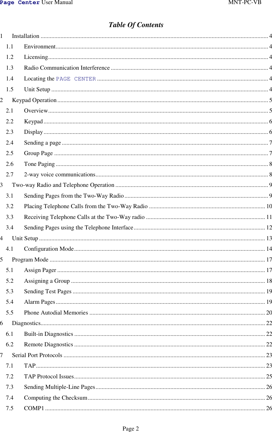
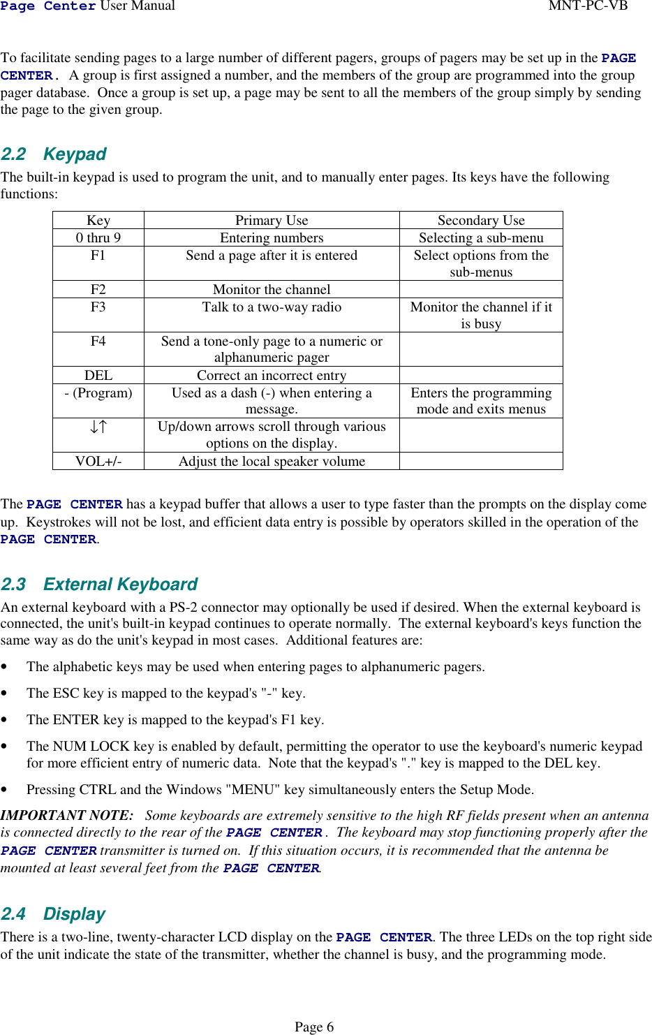
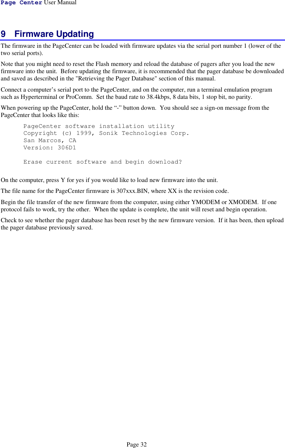
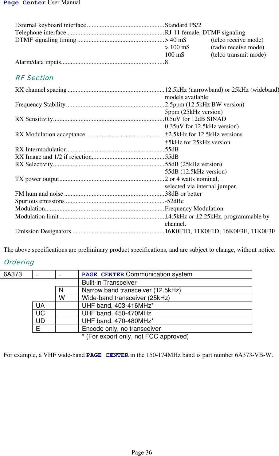
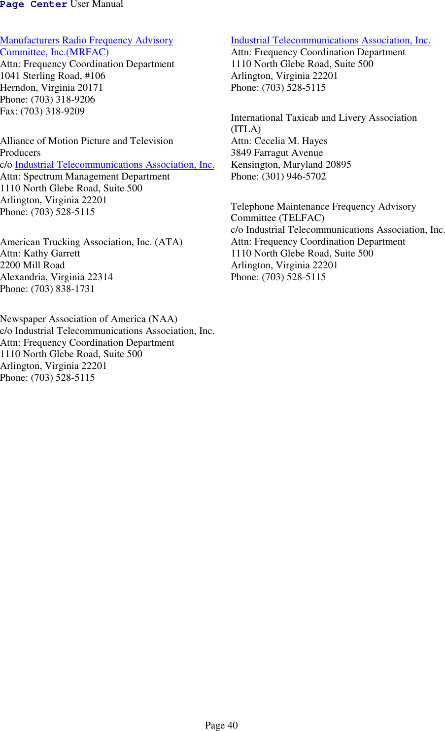
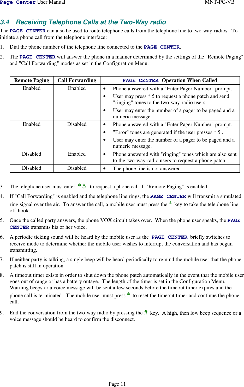
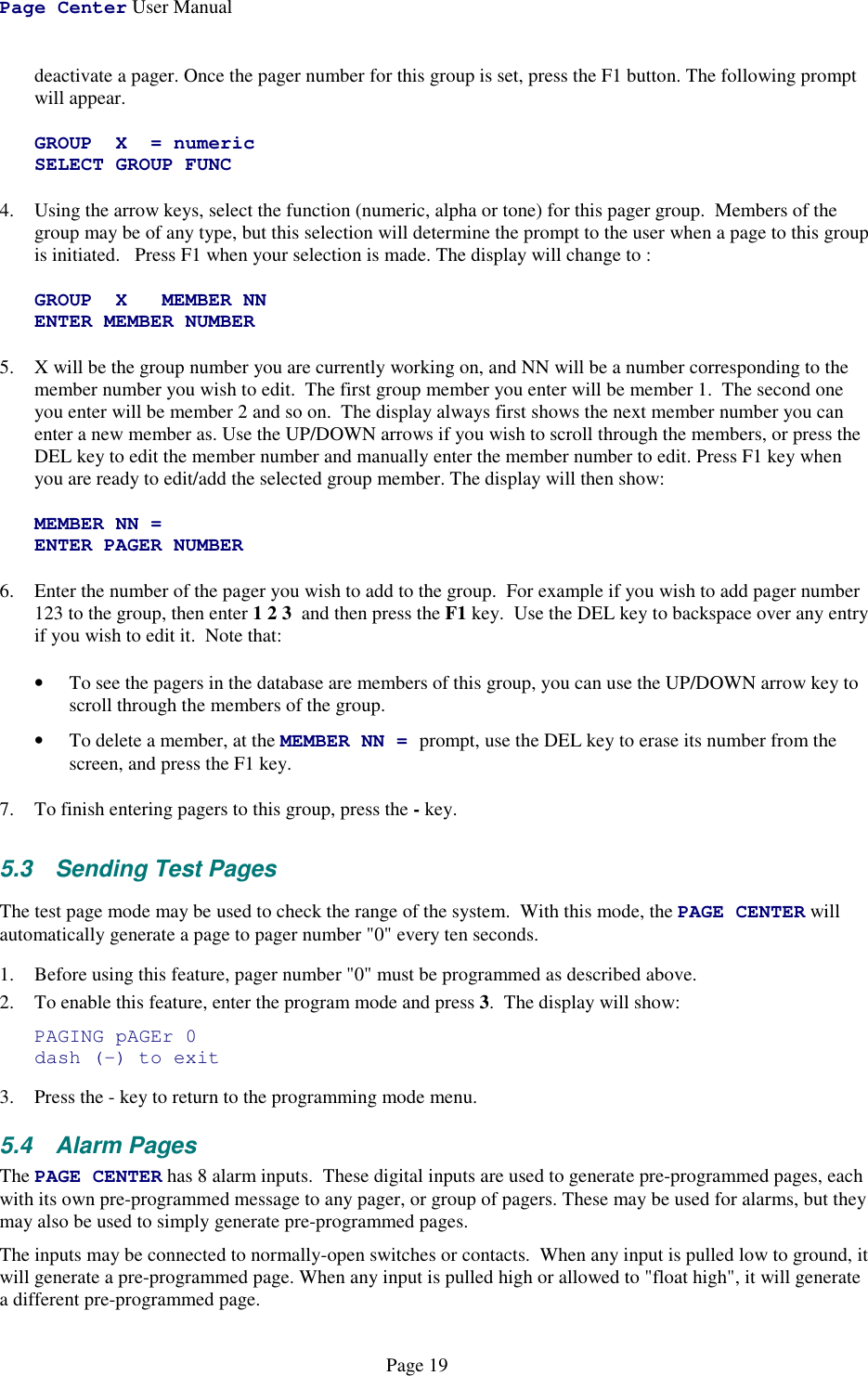
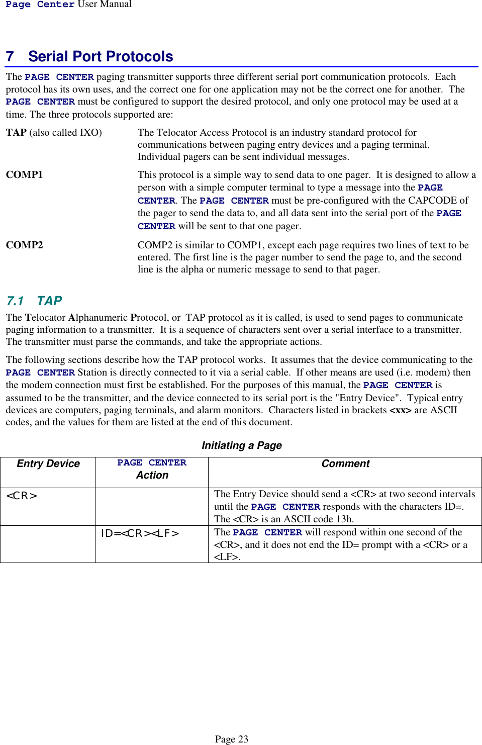
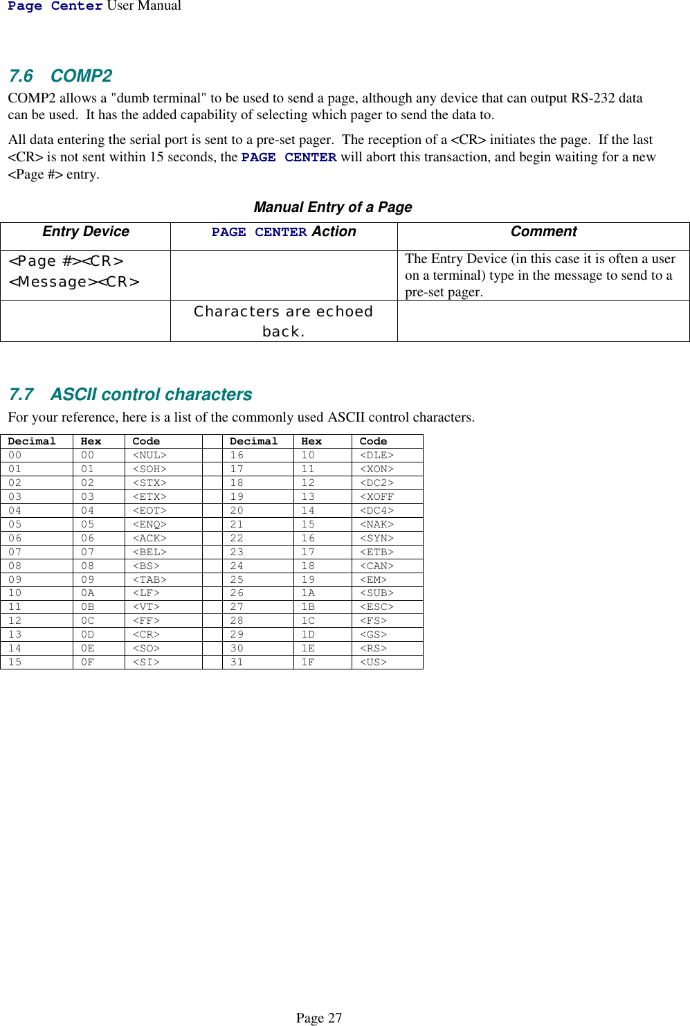
![Page Center User Manual MNT-PC-VBPage 93 Two-way Radio and Telephone OperationThe PAGE CENTER has a built-in radio transceiver enabling it to communicate with other two-way radios andto receive over-the-air commands to generate pages, connect to the telephone system, dial phone numbers andanswer incoming telephone calls. The telephone interface may be utilized for generating pages or initiatingphone patches with two-way-radios.To remotely control the PAGE CENTER with a two-way radio or from a telephone, the two-way radio ortelephone must be equipped with a DTMF encoder. All commands sent to the PAGE CENTER are entered viathe DTMF keypad, and in most cases, the commands are similar to the ones used locally on the PAGECENTER's built-in keypad. The two-way radio operation of the PAGE CENTER is a standard feature, but itmust be enabled before it will work3.1 Sending Pages from the Two-Way RadioThis section describes how to send a page with the PAGE CENTER using a DTMF keypad-equipped two-wayradio. The PAGE CENTER and the two-way radio must have previously been configured to communicate onthe same channel, and utilize the same CTCSS tones.To send a page to a pager from the two-way radio, you must:1. Send *9 to alert the PAGE CENTER that you intend to send a page.2. If desired, optionally listen to the receiver for the "Enter Pager Number" prompt, which is a sequence ofthree beeps. A series of alternating high and low beeps indicates an error in the command sequence or atimeout occurred. If voice prompts have been enabled, then a voice message will be heard instead of thebeeps.3. Enter the digits of the pager number you wish to page. If the pager's number is less than three digits inlength, then press the *key to terminate the pager's number. Note that the *key is not used to terminatethree digit pager numbers.4. If desired, optionally listen to the receiver for a low / high beep sequence, which signifies that the pagernumber was accepted. A series of alternating high and low beeps indicates an error in the pager number ora timeout occurred. If voice prompts have been enabled, then a voice message will be heard instead of thebeeps.5. Enter the numeric digits you wish to send to the pager. Do not enter any digits if you only wish to "beep"the pager. Note that the following DTMF keys have special meanings:DTMF Key Pager Character Comments* - Hyphen character# {none} Send the pageA Space characterB ] Right bracketC [ Left bracketD U Urgency indicator6. Press the # key to send the page.To send a new message to the same pager again, you may:1. Type *0 to alert the PAGE CENTER that you intend to send a page to the same pager number as before.2. Continue from step 4 of the instructions above to input the new message to be sent.](https://usermanual.wiki/Vytek/PC-VB/User-Guide-86641-Page-9.png)
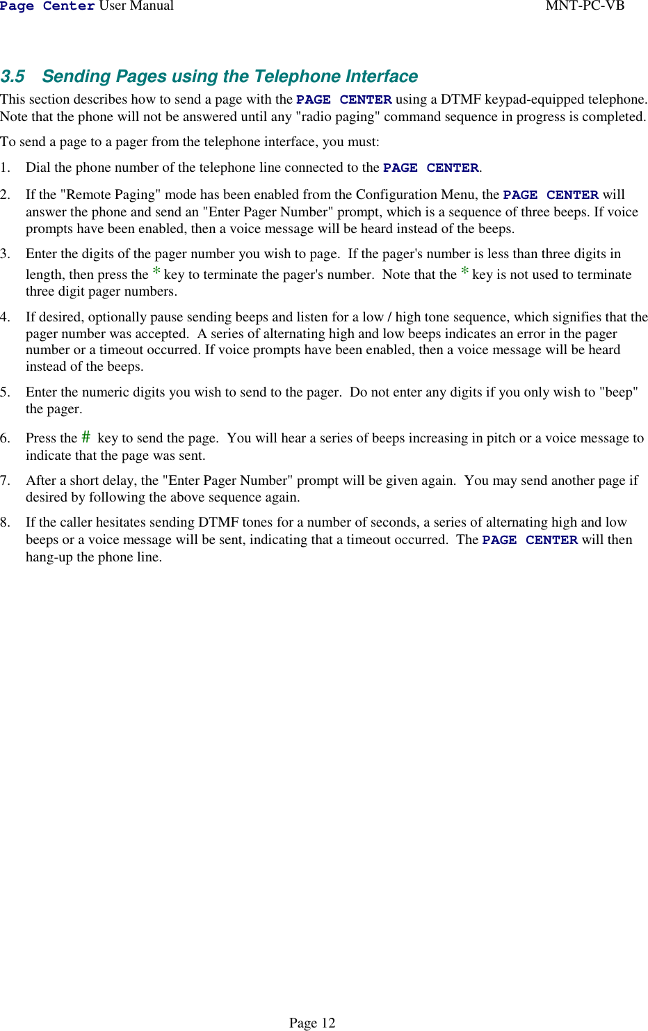
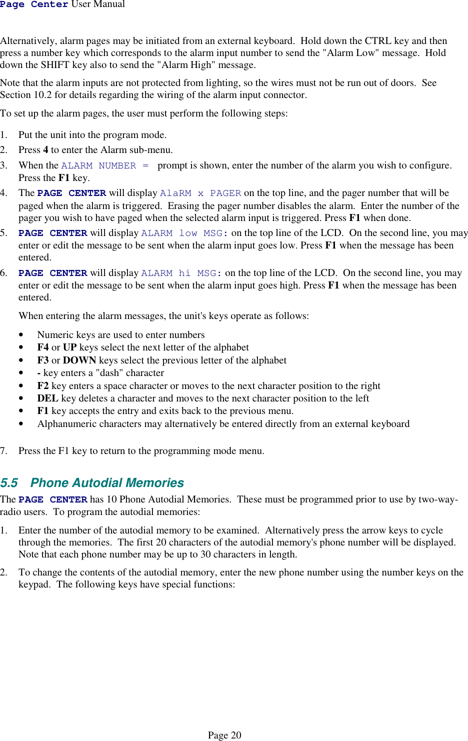
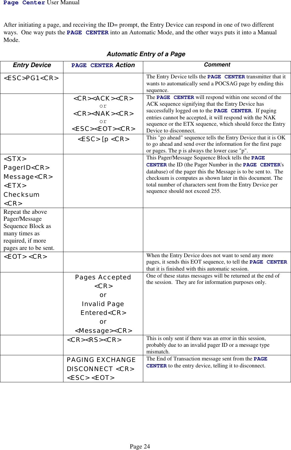
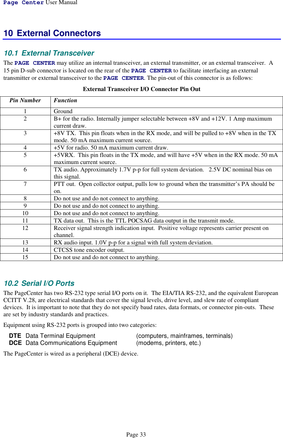
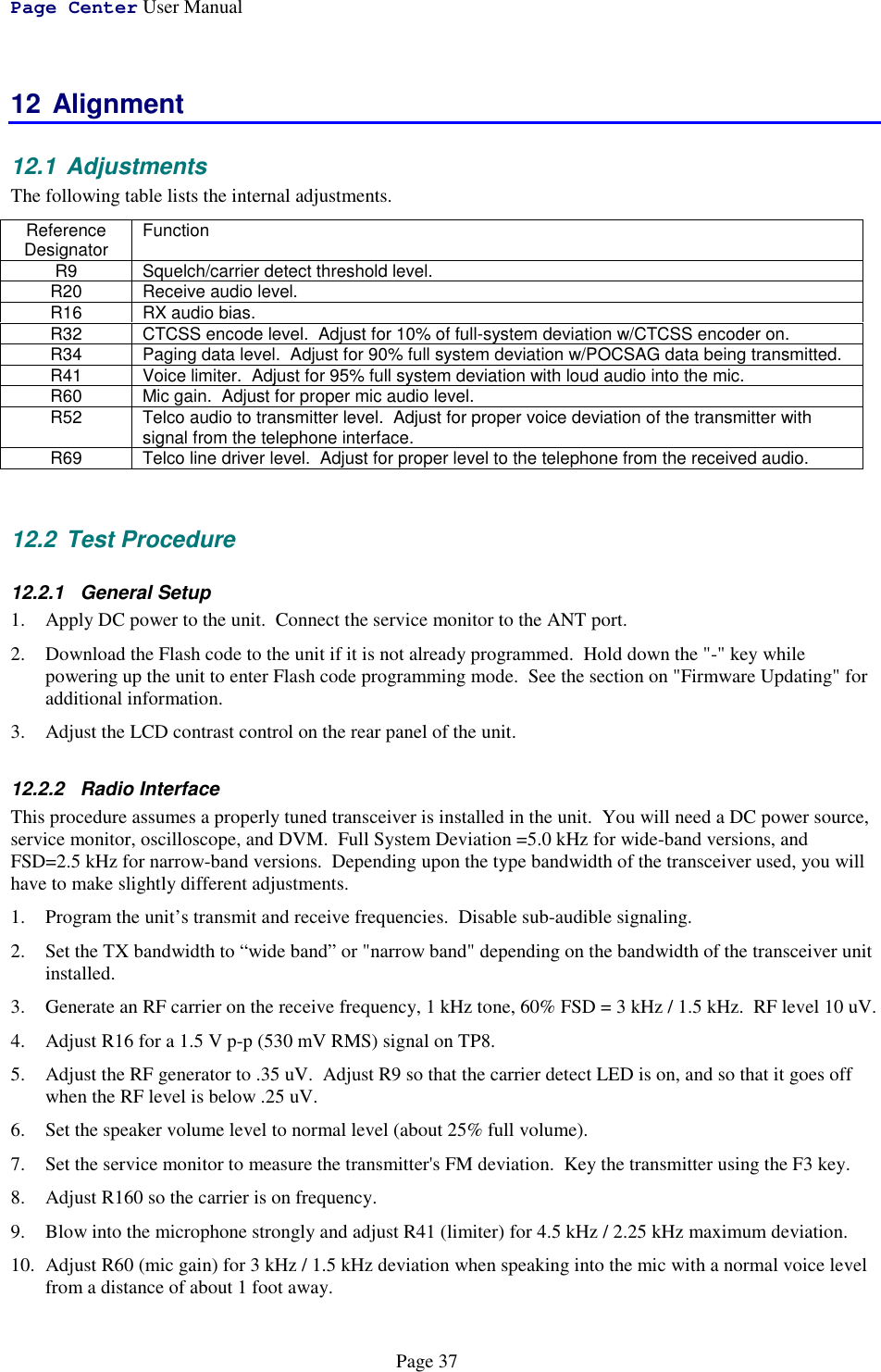
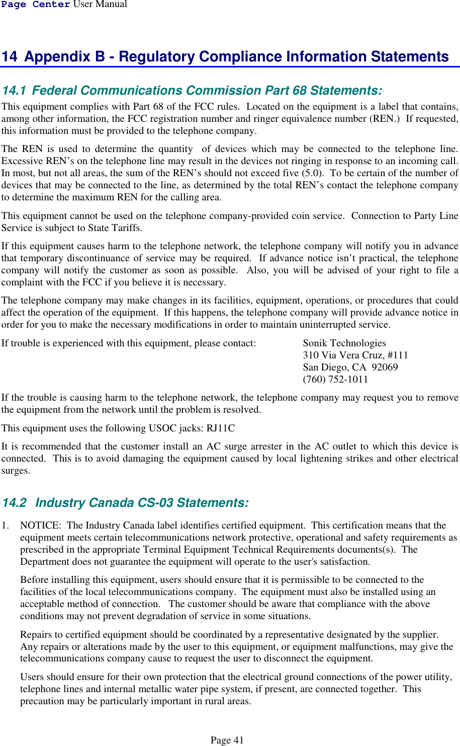
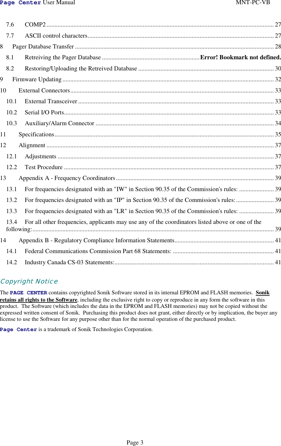
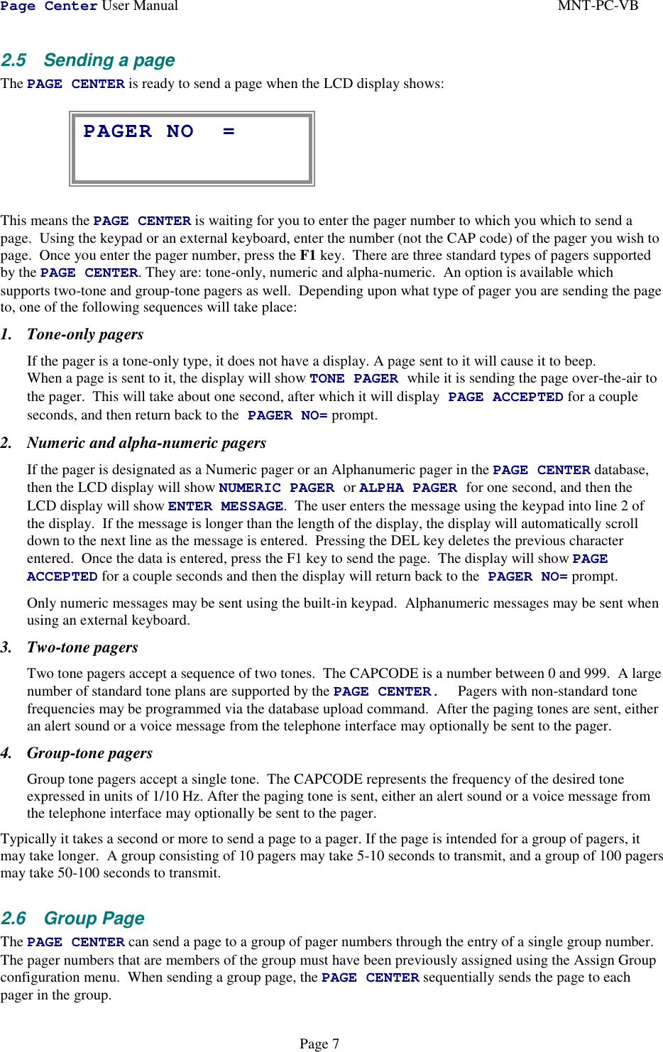
![Page Center User ManualPage 288 Database TransferFor convenience managing databases containing a large number of pagers, for backup purposes and to facilitatecloning databases from one unit to another, the PAGE CENTER database may be uploaded and downloadedfrom a host computer which is connected to either serial port which is configured for the TAP protocol.8.1 Database FormatThe PAGE CENTER database may be uploaded or downloaded as ASCII characters which can readily betransferred, stored and/or edited as desired. The format of the database output is as follows:DB1[0D]VERSION,{VERSION},{OPTIONS},[0D]SERIAL,{PORT},{BITS},{STOP},{PARITY},{FLOW},{BAUD},{TAP-TO},{COMP-TO},{MAN-TO},{PROTO},[0D]MODE,{SPKR},{BUSY},{REMOTE},{CALL},{AP-TIMER},{VOICE},{WARMUP},[0D]RADIO,{T-REF},{T-FREQ},{T-CTCSS},{BW},{R-REF},{R-FREQ},{R-CTCSS},{CD},{DATA},{TYPE},[0D]AUTODIAL,{MEMORY NUM},{PHONE NUM},[0D]PAGER,{0-999},{TYPE},{CAPCODE},{FORMAT},{GROUP},{ACTIVE},{DUR-A},{DUR-B},[0D]GROUP,{NUMBER},{PAGER NUM},{MEMBERS},{SPARE},{MEMBER 1},…{MEMBER N}[0D]DONE[0D]Where:DB1 Signifies that the database download follows[0D] Is an ASCII carriage returnVERSION Signifies that the version string follows{VERSION} Firmware version string{OPTIONS} Firmware optionsSERIAL Signifies that this line is data for a serial port{PORT} Port number for this line's data{BITS} Number of data bits (0= 7 bits, 1= 8 bits){STOP} Number of stop bits (0= 1 bit, 1= 2 bits){PARITY} Parity (0= No Parity, 1= Odd, 2= Even){FLOW} Flow control (0= None, 1= Xon/Xoff, 2= RTS/CTS){BAUD} Baud rate (0= 300, 1= 600, 2= 1200, 3= 2400, 4= 4800, 5= 9600, 6= 19200){TAP-TO} Timeout for TAP protocol in seconds{COMP-TO} Timeout for COMP protocol in seconds{MAN-TO} Timeout for manual entry mode in seconds{PROTO} Port protocol (0 = TAP, 1 = COMP1, 2 = COMP2)MODE Signifies that this line is data for mode settings{SPKR} Speaker enable mode on/off{BUSY} Busy channel lockout on/off{REMOTE} Remote enable on/off{CALL} Call forwarding on/off{AP-TIMER} Autopatch timer in seconds{VOICE} Voice Prompts on/off{WARMUP} Warmup signal on/off](https://usermanual.wiki/Vytek/PC-VB/User-Guide-86641-Page-28.png)
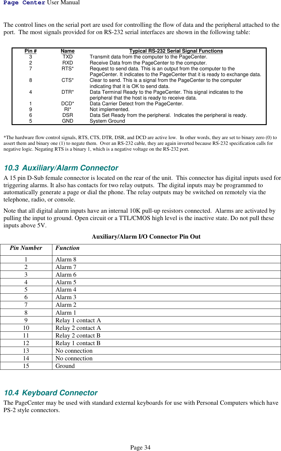
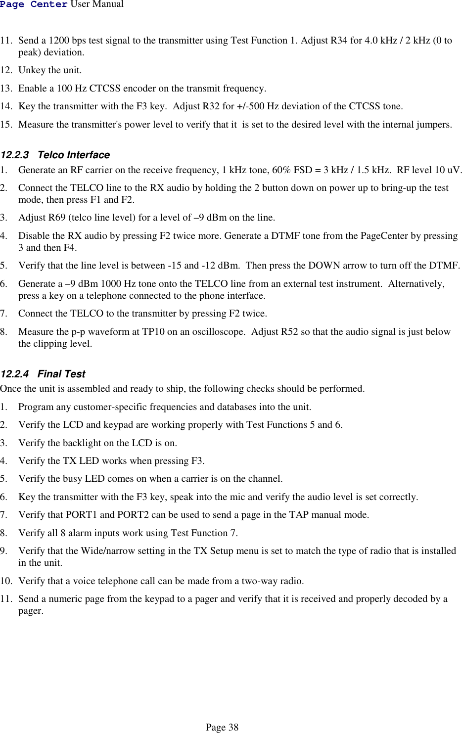
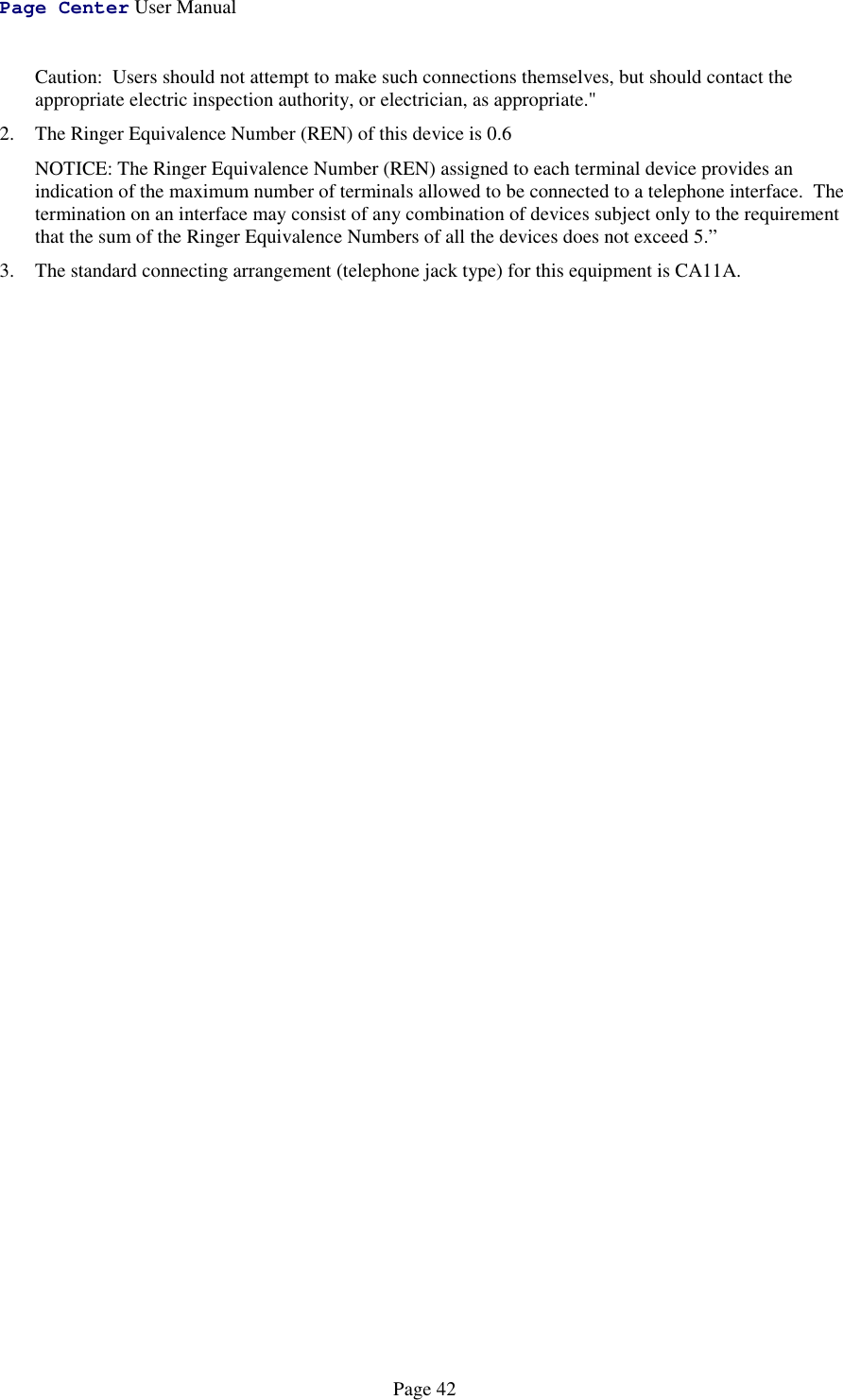
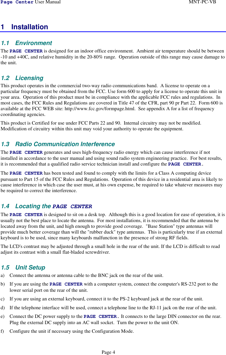
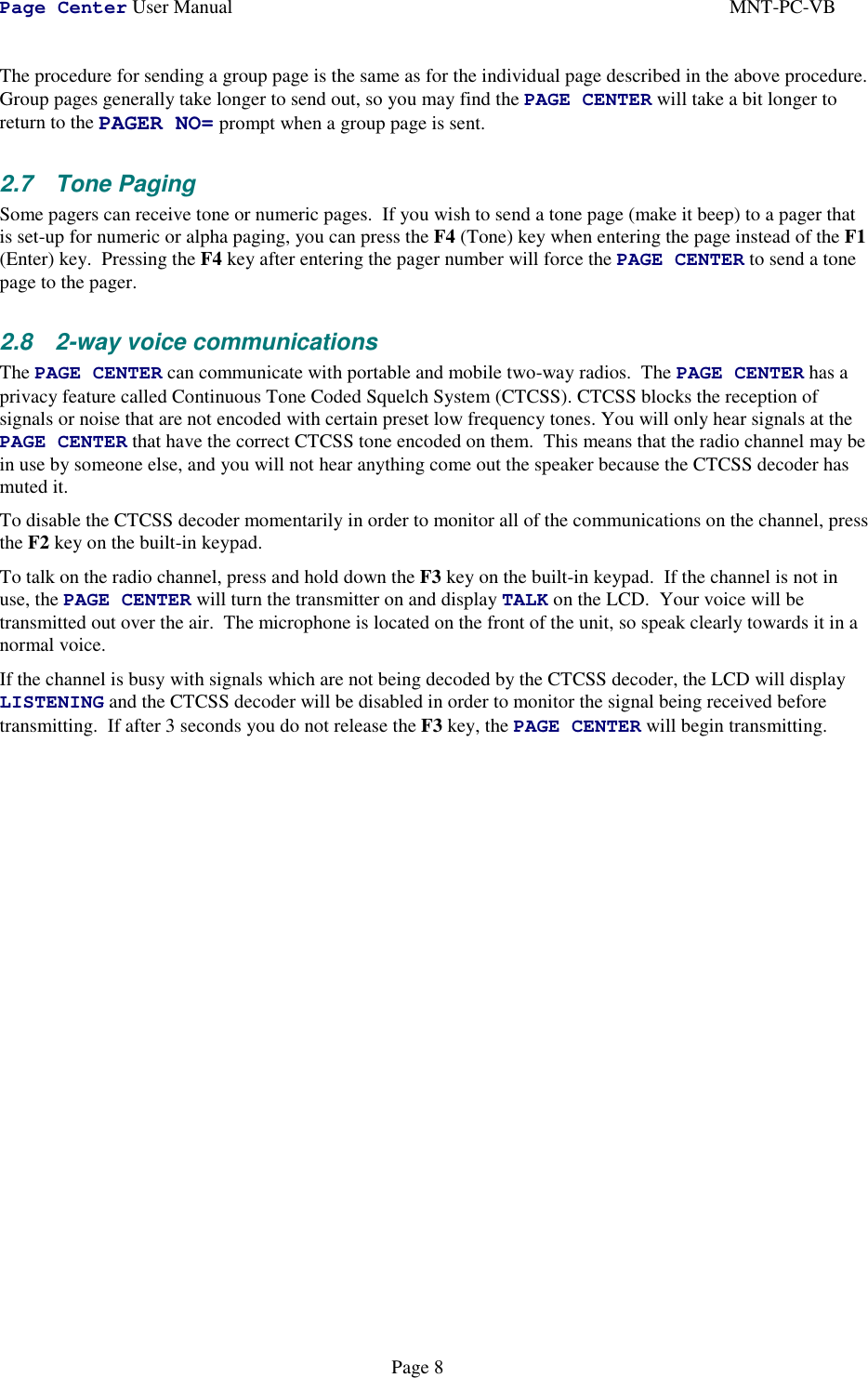
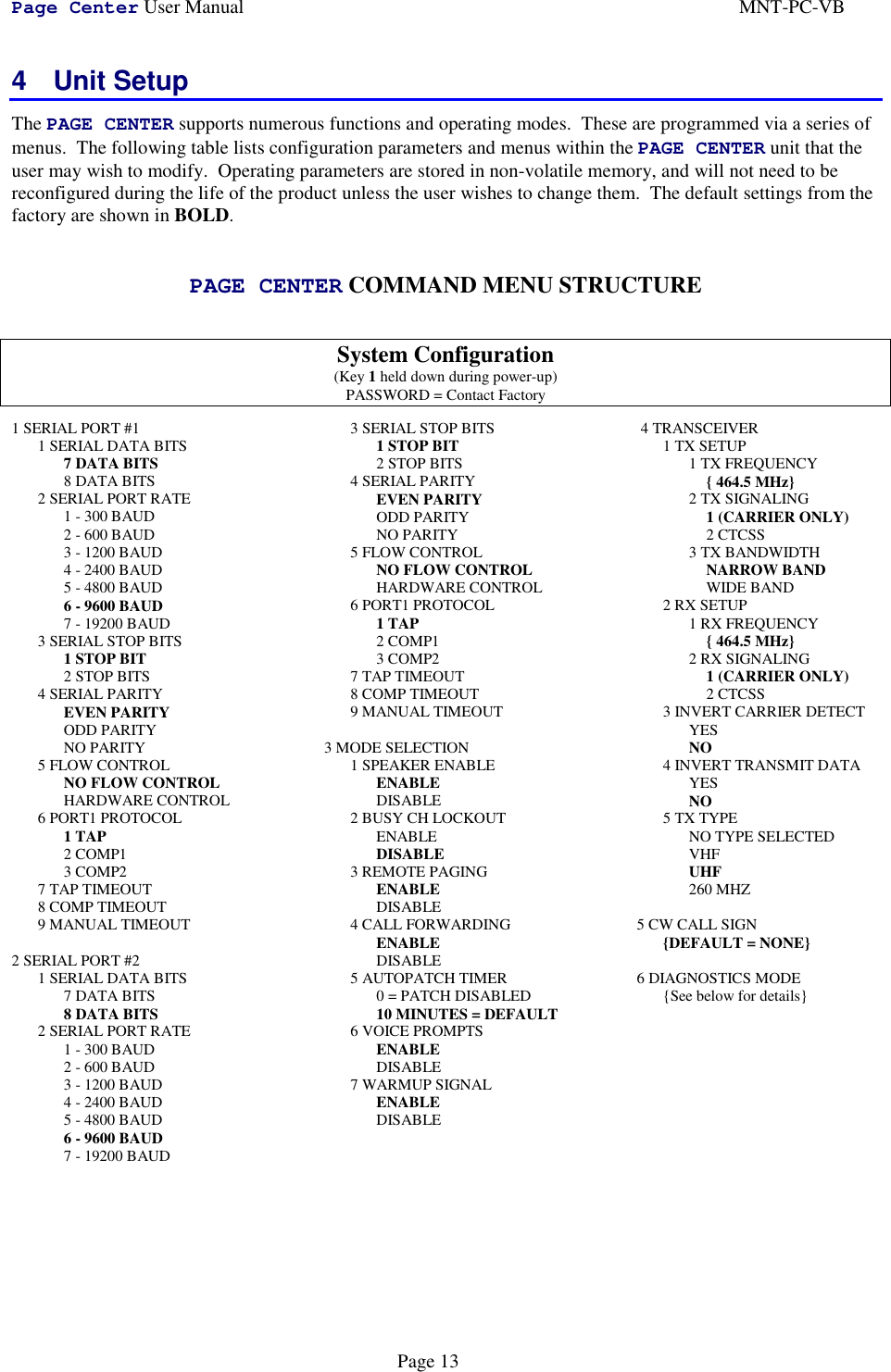
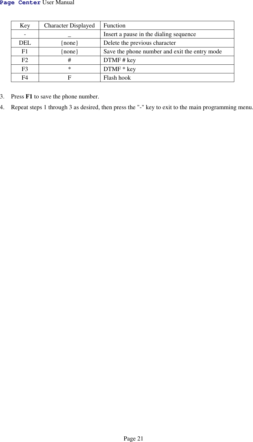
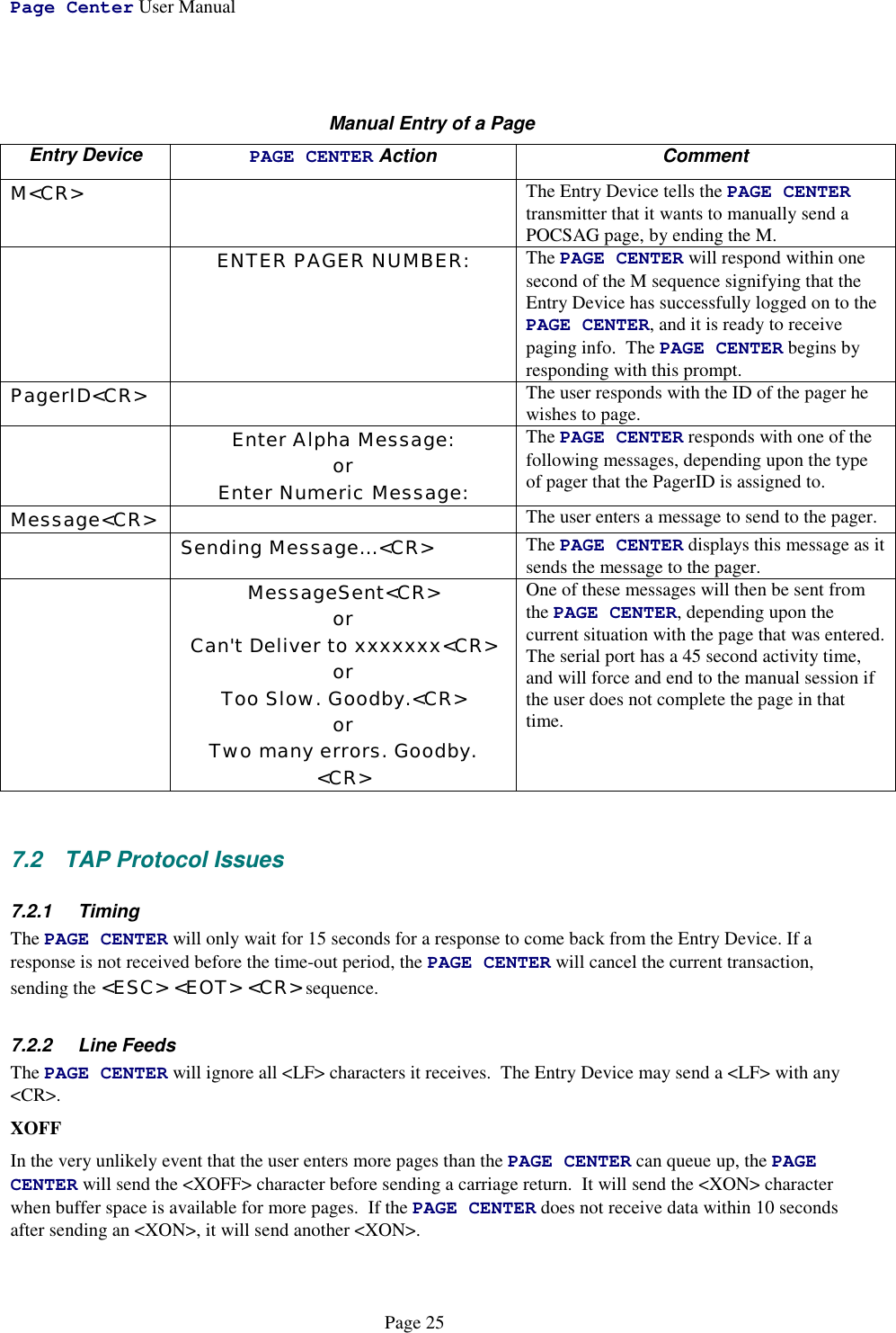
![Page Center User ManualPage 29RADIO Signifies that this line is data for the radio transceiver{T-REF} Transmit reference frequency in Hz{T-FREQ} Transmit frequency in Hz{T-CTCSS} Transmit CTCSS code (-1 = CTCSS off){BW} Transmit Bandwidth (0= wide, 1= narrow){R-REF} Receive reference frequency in Hz{R-FREQ} Receive frequency in Hz{R-CTCSS} Receive CTCSS code (-1 = CTCSS off){CD} Carrier detect inversion on/off{DATA} Transmit data inversion on/off{TYPE} Transceiver type codeAUTODIAL Signifies that this line is data for an autodial memory{MEMORY NUM} Memory number{PHONE NUM} Phone numberPAGER Signifies that this line is the data for a pager{0-999} Pager number for the data on this line{TYPE} Pager type: ALPHA, NUMERIC, TONE, ALERT or VOICE{CAPCODE} Pager CAPCODE. If the pager is a group it will be the group number minus 1. If DUR-A is not zero, CAPCODE contains frequencies of the two tones with the first tone's frequency in units of 1/10 Hz in bits 0 to 15 and the second tone's frequency in units of 1/10 Hz in bits 16 to 31.{FORMAT} Paging format: POC512, POC1200, POC2400, TWO-TONE or GROUP-TONE{GROUP} Is either Y if it is a group pager, or N if it is not a group pager{ACTIVE} Is either Y is the pager is enabled, or N if it is de-activated{DUR-A} Duration of first tone in units of 50 mS for two-tone pagers with random frequencies, 0 otherwise.{DUR-B} Duration of second tone in units of 50 mS for two-tone pagers with random frequencies, 0 otherwise.GROUP Signifies that this line is the data for a group of pagers{NUMBER} Group number (1-16){PAGER NUM} Pager number that references this group{MEMBERS} Number of pagers assigned to this group{SPARE} A blank entry for future use{MEMBER 1} The pager number for the first member. All other members follow this one, separated by commas.{MEMBER N} This is the pager number for the final member of the groupDONE This entry signifies the end of the database.8.2 Retreiving the DatabaseThe PAGE CENTER will send the contents of its database out the serial port when it is given the command<ESC>SDB<CR>. The database is sent out at the currently configured baud rate in an ASCII format, withcommas between the parameters and a <CR> at the end of each line. Example Output of the database:DB1[0D]VERSION,307D31,1,SERIAL,0,0,0,2,0,5,30,60,90,0,SERIAL,1,0,0,2,0,5,30,60,90,0,MODE,1,0,1,1,10,1,1,RADIO,6250,462925000,-1,0,6250,462925000,-1,0,0,2,[0D]AUTODIAL,0,8531212,[0D]](https://usermanual.wiki/Vytek/PC-VB/User-Guide-86641-Page-29.png)
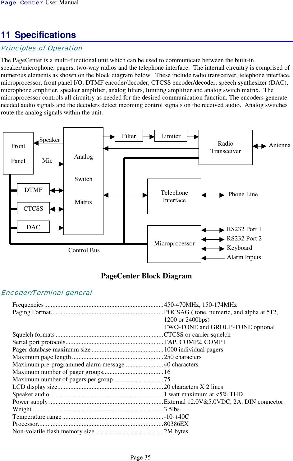
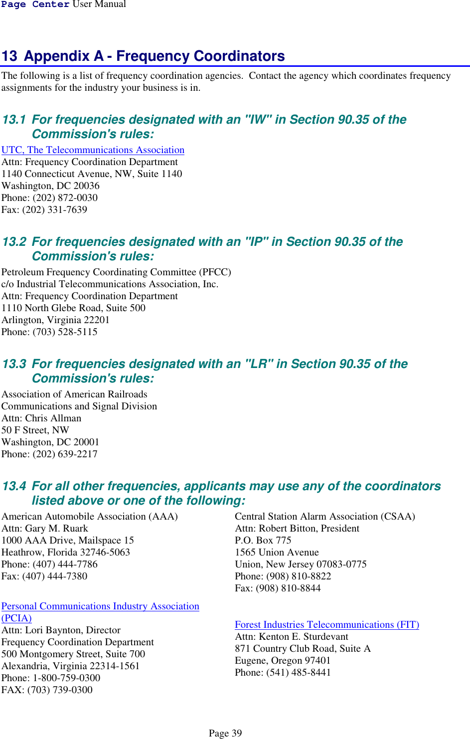
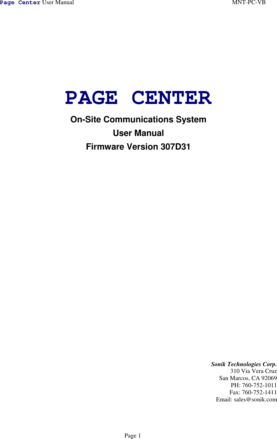
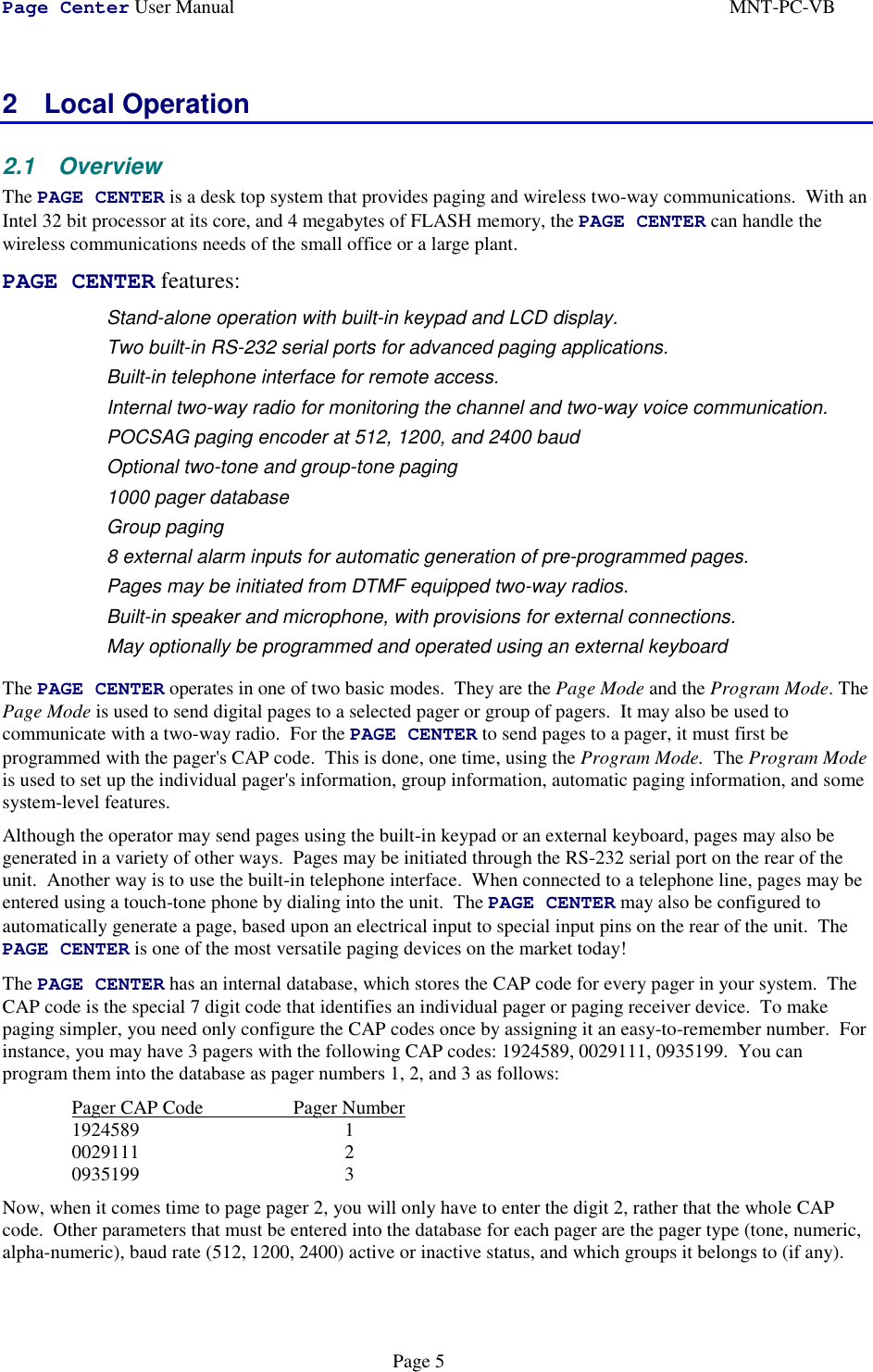
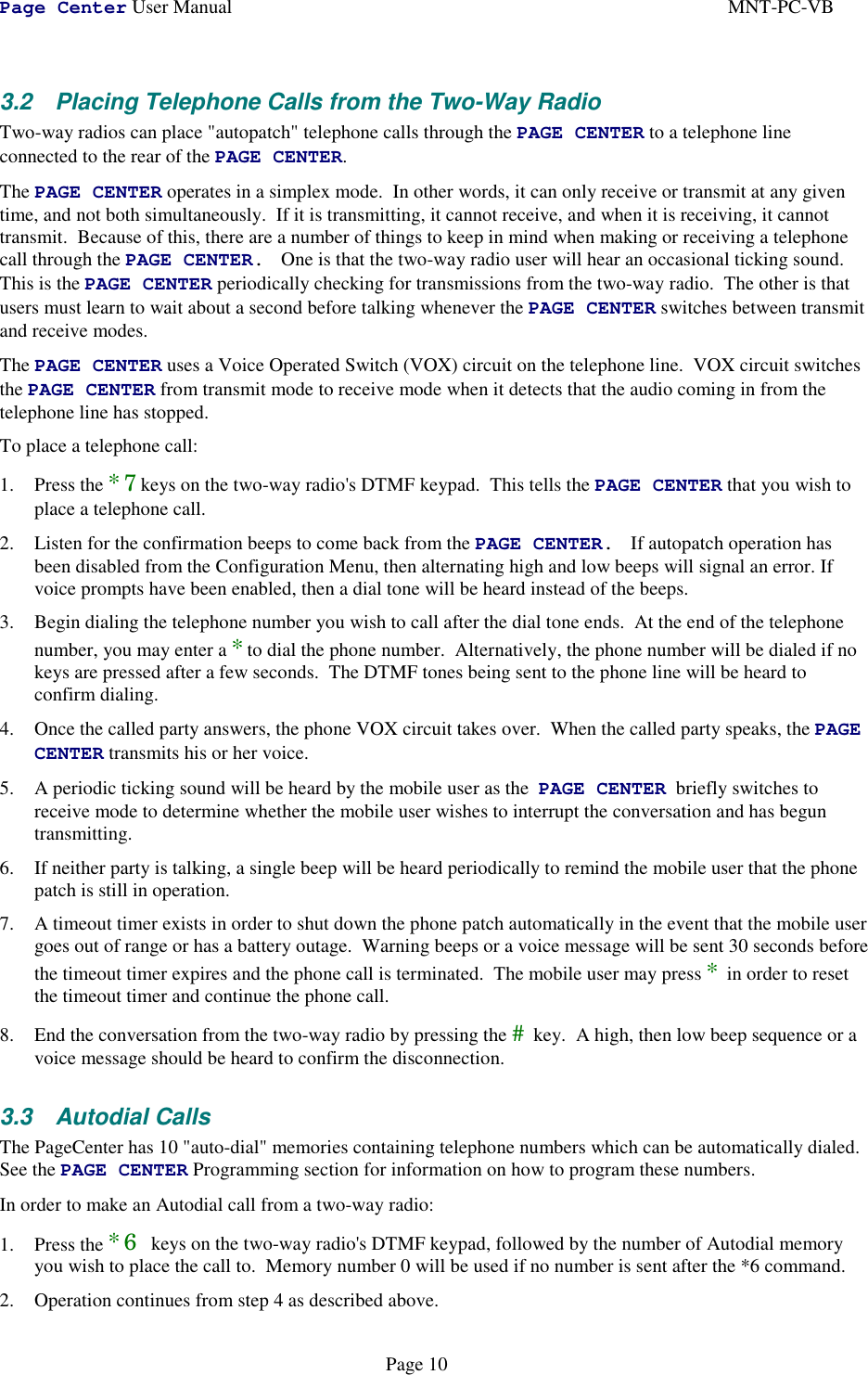
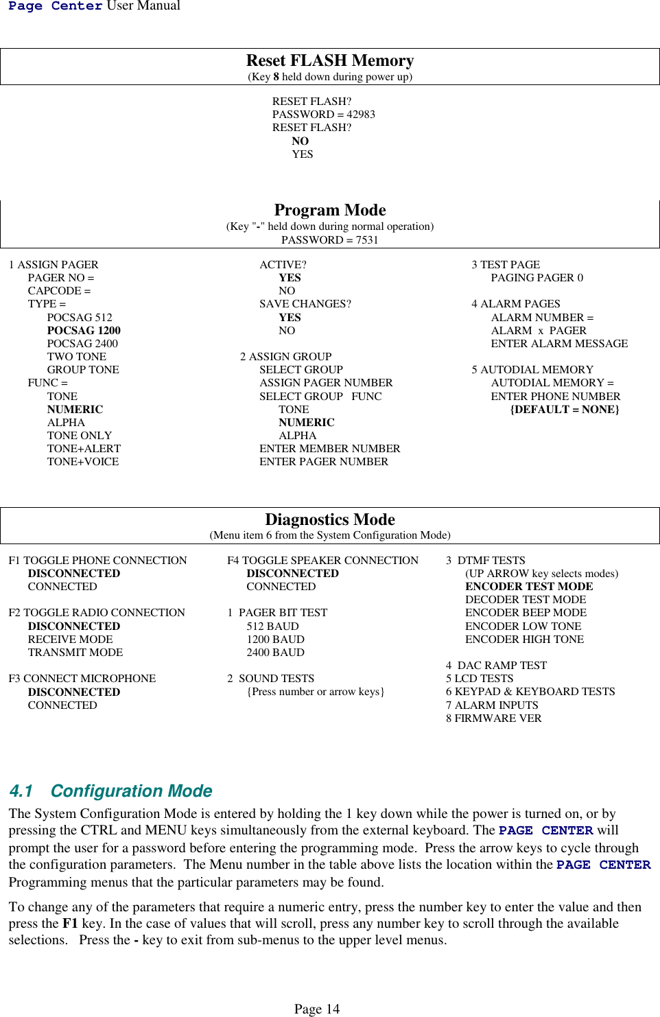
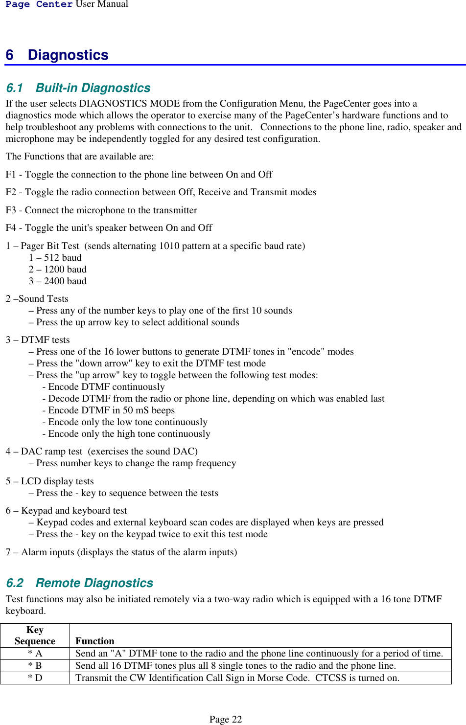
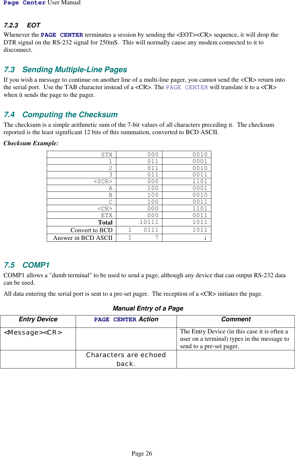
![Page Center User ManualPage 30AUTODIAL,1,18005551212,[0D]AUTODIAL,2,,[0D]AUTODIAL,3,,[0D]AUTODIAL,4,,[0D]AUTODIAL,5,,[0D]AUTODIAL,6,,[0D]AUTODIAL,7,,[0D]AUTODIAL,8,,[0D]AUTODIAL,9,,[0D]PAGER,0,ALPHA,9,POC1200,N,Y,0,0,[0D]PAGER,1,NUMERIC,0,POC2400,Y,Y,0,0,[0D]PAGER,2,NUMERIC,2,POC1200,N,Y,0,0,[0D]PAGER,3,NUMERIC,100303,POC1200,N,Y,0,0,[0D]PAGER,4,NUMERIC,4,POC1200,N,Y,0,0,[0D]PAGER,5,NUMERIC,5,POC1200,N,Y,0,0,[0D]PAGER,10,NUMERIC,10,POC2400,N,Y,0,0,[0D]PAGER,11,NUMERIC,11,POC1200,N,Y,0,0,[0D]PAGER,12,NUMERIC,12,POC512,N,Y,0,0,[0D]PAGER,13,ALPHA,13,POC512,N,Y,0,0,[0D]PAGER,14,ALPHA,14,POC1200,N,Y,0,0,[0D]PAGER,17,NUMERIC,0,0,0,Y,Y,0,0,[0D]PAGER,20,ALPHA,20100,POC512,N,Y,0,0,[0D]PAGER,21,NUMERIC,21,POC1200,N,Y,0,0,[0D]PAGER,22,NUMERIC,2200,POC1200,N,Y,0,0,[0D]PAGER,100,TONE,99,POC1200,N,Y,0,0,[0D]PAGER,101,NUMERIC,1010,POC512,N,Y,0,0,[0D]PAGER,102,ALPHA,1020,POC512,N,Y,0,0,[0D]PAGER,103,TONE,1030,POC1200,N,Y,0,0,[0D]PAGER,104,NUMERIC,1040,POC1200,N,Y,0,0,[0D]PAGER,105,ALPHA,1050,POC1200,N,Y,0,0,[0D]PAGER,105,ALPHA,1050,POC1200,N,Y,0,0,[0D]PAGER,106,TONE,1060,POC2400,N,Y,0,0,[0D]PAGER,107,NUMERIC,1070,POC2400,N,Y,0,0,[0D]PAGER,108,ALPHA,9,POC1200,N,Y,0,0,[0D]PAGER,109,ALPHA,9,POC1200,N,Y,0,0,[0D]PAGER,110,ALPHA,10,POC1200,N,Y,0,0,[0D]PAGER,115,NUMERIC,0,,Y,Y,0,0,[0D]PAGER,123,ALPHA,123,POC512,N,Y,0,0,[0D]PAGER,125,ALERT,131195,TWO-TONE,N,Y,0,0,[0D]PAGER,300,TONE,3000,GROUP-TONE,N,Y,0,0,[0D]PAGER,301,TONE,30000,GROUP-TONE,N,Y,0,0,[0D]PAGER,400,TONE,4000,GROUP-TONE,N,Y,0,0,[0D]PAGER,500,TONE,5000,GROUP-TONE,N,Y,0,0,[0D]PAGER,510,TONE,655380000,TWO-TONE,N,Y,20,20,[0D]PAGER,556,ALPHA,0,,Y,Y,0,0,[0D]PAGER,599,NUMERIC,599,POC1200,N,Y,0,0,[0D]PAGER,998,NUMERIC,997,POC1200,N,Y,0,0,[0D]PAGER,999,TONE,12345,POC2400,N,Y,0,0,[0D]GROUP,1,1,23,,100,101,102,103,104,105,106,107,108,109,110,999,104,104,105,105,105,104,106,107,108,106,109[0D]GROUP,5,556,3,,123,122,121[0D]GROUP,15,115,5,,123,10,1,23,20[0D]GROUP,16,17,3,,100,103,106[0D]DONE[0D]8.3 Restoring/Uploading the Retreived DatabaseIf the database is stored on a disk in the format shown above, it may be re-loaded into the PageCenter. Use aterminal emulation program to send the ASCII file into either serial port in a plain-text format. The serial portmust be configured for the TAP protocol.The PageCenter will answer every line sent into it with an OK> if the line was acceptable, or ER> if there wasan error in it. If any errors occur during uploading, a message will be displayed at the end of the uploadsequence and the information received will not be saved. If this occurs, reduce the data rate of the port in use orenable hardware flow control, then retry the upload operation.Note that the “DB1[0D]” sequence in the first line tells the PageCenter that a database file is going to be sentto it. The word “DONE” at the end of the file tells the PageCenter that the file has been sent. Once the word](https://usermanual.wiki/Vytek/PC-VB/User-Guide-86641-Page-30.png)
![Page Center User ManualPage 31DONE is received by the PageCenter, it will copy the database into its FLASH memory only if no errors weredetected.8.3.1 Erasing Pagers or Groups from the DatabaseUploading the database file to the PageCenter only adds and re-programs the pagers and groups specified. Itdoes not erase other pagers with entries stored in the unit's memory.If you want the pager database erased, use a text editor to add a line before the first PAGER entry in thedatabase. The only characters on the line should be:ERASEDATABASE[0D]This will tell the PageCenter to erase whatever is in its database before it adds the new pagers and groups fromthe ASCII file. If you only wish to erase the group information, and not the individual pagers, put a line in thefile that reads:ERASEGROUPS[0D]8.3.2 Programming Two-Tone Pagers with Non-Standard FrequenciesTwo-tone or group-tone pagers using non-standard frequencies and durations may be programmed via thedatabase upload command. Use a text editor to create an entry in the database file for the pager as followsbefore uploading the file to the unit:PAGER,{0-999},{TYPE},{CAPCODE},{FORMAT},N,{ACTIVE},{DUR-A},{DUR-B},Where:PAGER Signifies that this line is the data for a pager{0-999} Pager number for the pager{TYPE} Pager type: TONE, ALERT or VOICE{CAPCODE} Bits 0 to 15 = First tone's frequency in units of 1/10 Hz Bits 16 to 31 = Second tone's frequency in units of 1/10 Hz{FORMAT} Paging format: TWO-TONE or GROUP-TONE{ACTIVE} Is either Y is the pager is enabled, or N if it is de-activated{DUR-A} Duration of the first tone in units of 50 mS{DUR-B} Duration of the second tone in units of 50 mS. Set to 0 for group-tone pagers.8.3.3 Programming the Unit's ConfigurationThe unit configuration data stored in the SERIAL, MODE, RADIO and AUTODIAL entries are normallyignored when the database file is uploaded to the PageCenter as a security feature in order to preventunauthorized users from changing the unit's configuration.If it is desired to change the PageCenter's configuration with data downloaded previously from a PageCenterunit, use a text editor to add the following line to the database file immediately after the "DB1" entry:PASSWORD,xxxxxx,[0D]Where xxxxxx is the same password required to access the Configuration Mode from the PageCenter's frontpanel.](https://usermanual.wiki/Vytek/PC-VB/User-Guide-86641-Page-31.png)