WENZHOU MTLC ELECTRIC APPLIANCES ZW2P WIRELESS SWITCH User Manual
WENZHOU MTLC ELECTRIC APPLIANCES CO., LTD. WIRELESS SWITCH
Users Manual
INSTALLATION INSTRUCTIONS
-01-
DESCRIPTION
FEATURES
ZW2P
Plug-in Appliance
Voltage................................................................................ 120VAC, 60Hz
Maximum Load requirements:
Incandescent......................................................................................600W
Frequency................................................................................ 908.42 MHz
Operating Temperature............................................................... 32-104° F
Range.................................................................Up to 100 feet line of sight
between the Wireless Controller and the closest Z-Wave receiver module.
Wireless Lighting Control
SPECIFICATIONS
Module
Resistive...........................................................................................1800W
In a Z-Wave network, each device is designed to act as a wireless repeater.
WARNINGS AND CAUTIONS
-02-
OPERATIONS
Basic Operation
The connected light can be turned ON in two ways:
1. With a Z-wave remote.
2. Manually with the program button on the Z-Wave module.
Remote Control
Z-Wave remotes provide control of an Individual device, Groups of devices
and Scenes. Please refer to your remote control's instructions for detail on
its capabilities and instructions for adding and controlling devices.
Manual Control
The Program Button on the ZW2P appliance module allows the user to:
Provides manual and remote control
Blue LED show feedback from the controller
Ease of installation(no new wiring)
Compatible with other Z-Wave enabled devices
This appliance module is a Z-Wave enabled device and is fully compatible
with any Z-Wave enabled network. Z-Wave enabled devices displaying
the Z-Wave logo can also be used with it regardless of the manufacturer.
Repeaters will retransmit the RF signal from one device to another until the
intended device is reached. This ensures that the signal is received by its
intended destination by routing the signal around obstacles and radio dead
spots.
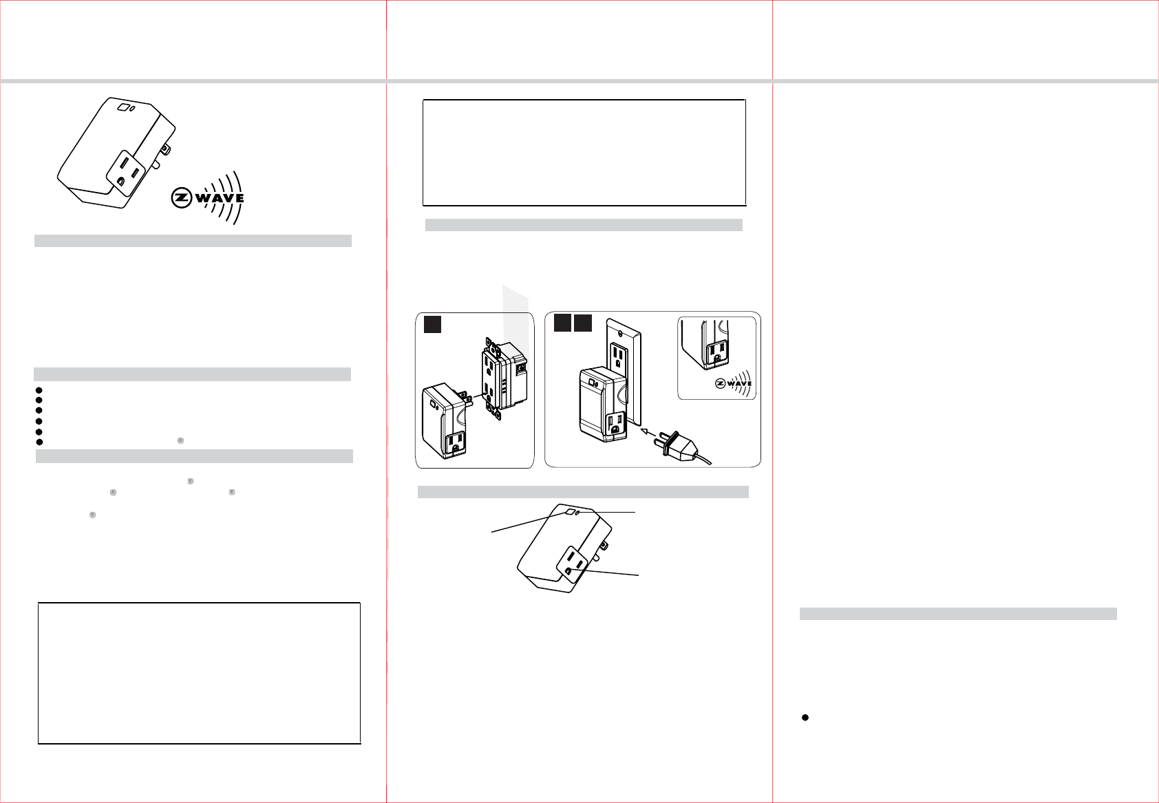
INSTALLATION
1. Plug the ZW2P Appliance Module into a 120VAC,60HZ outlet.
2
2. Plug the appliance or other electric device into the ZW2P Appliance
does not exceed 600 Watts.
3. Turn the knob or switch on the appliance or electric device to the ON
3
1.To manually turn ON the ZW2P Appliance Module, press and release the
program button.The blue indicator LED will turn ON, and the appliance or
device plugged into the ZW2P Appliance Module will also turn ON.
2.To manually turn OFF the ZW2P Appliance Module, simply press and
release the program button. The blue indicator will turn OFF and the appliance
or device plugged into the ZW2P Appliance Module will also turn OFF.
1
The four possible responses are:
- It will respond to ALL-ON and the ALL-OFF command (default).
- It will not respond to ALL-ON or ALL-OFF commands.
- It will respond to the ALL-OFF command but will not respond to the ALL-ON
command.
- It will respond to the ALL-ON command but will not respond to the ALL-OFF
command
All On/All Off
Depending upon your primary controller, the ZW2P appliance module can
be set to respond to ALL ON and ALL OFF commands in up to four different
ways. Some controllers may not be able to change the response from its
default setting. Please refer to your controller’s instructions for information
on whether or not it supports the configuration function and if so, how to
advanced controller. However, basic remotes do not have this capability.
ADVANCED OPERATION
The following Advanced Operation parameters require that you have an
Blue LED indicator
change this setting.
WIRELESS RANGE
This device complies with the Z-Wave standard of open-air, line of sight
transmission distances of 65 feet. Actual performance in a home depends
on the numbers of walls between the remote controller and the destination
device, the type of construction and the number of Z-Wave enabled devices
installed in the control network.
Things to consider regarding RF range:
- Each wall or obstacle (i.e.:refrigerator, big screen TV, etc.)between the
remote or a Z-Wave device and the destination device will reduce the
maximum range by approximately 25-30%.
-03-
Motor.................................................................................................1/2 HP
Z-Wave controled AC outlet
Ground 3-wire power connection for safety
Module. Make sure the appliance or electric device to be controlled
position.
Z-Wave Outlet
Program Button
To reduce the risk of electric shock, this product has a grounding
type plug that has a third (grounding) pin. This plug will only fit
into a grounding type power outlet. If the plug does not fit into the
outlet, connect a qualified electrician to install the proper outlet .
Do not change the plug in any way.
To be installed and/or used in accordance with approprite electrical codes
please consult a qualified electrician.
and regulations. Exercise extreme caution when using Z-Wave devices to
control appliances. Operation of the Z-Wave device may be in a different
room than the controlled appliance, also an unintentional activation may
occur if the wrong button on the remote is pressed. Z-Wave devices may
automatically be powered on due to timed event programming.Depending
upon the appliance, these unattended or unintentional operation could
If you are unsure or uncomfortable about performing the installation,
possibly result in a hazardous condition.
3. Refer to the instruction for your primary controller to access the setup
function and include or exclude devices.
By default setting , the led state is as same as relay state. For example, if relay
If configuration variable value "0" is set to 255 /0xFF (by
Configuration details
a. valid variable value, 0 (other variable value will be ignored)
b. valid configuration value, 0 /0xFF (other configuration value will be ignored)
c. valid configuration value bytes, 1 byte (other configuration value will be ignored)
is drived<00FF>led will be turned on.We use command_class_configuration to
configure led state.
default it is "0") led state will be contrary with relay state.
command_class_configuration
INSTALLATION INSTRUCTIONS
-05--04-
WARRANTY INFORMATION
Our company warranties its products to be free of defects in materials and
workmanship for a period of two (2) years. There are no obligations or
out of or in connection with the use or performance of this product or
other indirect damages with respect to loss of property, revenue, or profit,
or cost of removal, installation or reinstallation.
liabilities on the part of our company for consequential damages arising
Jun,2011
Restoring Factory Defaults
All Configuration Parameters can all be restored to their factory default settings
by using your primary controller to reset the device.
Over-Current Protection
Additional over-current protection is provided by an internal fuse which is
not user serviceable. Check your home’s circuit breakers before concluding
that the product must be replaced.
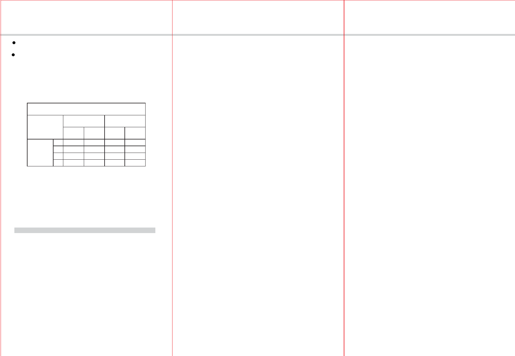
From the Remote (or repeating Z-Wave module) to
destination device:
Type of
Construction
Wood Frame with
Drywall
Brick, Tile or
Concrete
Plastic
J-Boxes*
Metal
J-Boxes
Plastic
J-Boxes*
Metal
J-Boxes
Number of
Walls or
Obstacles
0** 100’ 80’ 100’ 80’
1 70’ 56’ 60’ 48’
2 49’ 39’ 36’ 29’
3 34’ 27’ 21’ 17’
Z-Wave Enabled Devices.
- Wall mounted Z-Wave devices installed in metal junction boxes will suffer
a significant loss of range (approximately 20%) since the metal box blocks
a large part of the RF signal.
Effects of Home Construction on Wireless Range Between
The distances shown in the table below are typical examples.Actual
performance in your home will vary .
Note:
- Brick, tile or concrete walls block more of the RF signal than walls made
of wooden studs and plasterboard (drywall).
FCC STATEMENT
1. This device complies with Part 15 of the FCC Rules.
Operation is subject to the following two conditions:
(1) This device may not cause harmful interference, and
(2) This device must accept any interference received, including interference that may cause
undesired operation.
2. Changes or modifications not expressly approved by the party responsible for compliance could
void the user’s authority to operate the equipment.
FCC ID: ZZH-ZW2P
NOTE: This equipment has been tested and found to comply with the limits for a
Class B digital device, pursuant to Part 15 of the FCC Rules. These limits are
designed to provide reasonable protection against harmful interference in a
residential installation. This equipment generates, uses and can radiate radio
frequency energy and, if not installed and used in accordance with the
instructions, may cause harmful interference to radio communications. However,
there is no guarantee that interference will not occur in a particular installation.
If this equipment does cause harmful interference to radio or television reception,
which can be determined by turning the equipment off and on, the user is
encouraged to try to correct the interference by one or more of the following
measures:
-- Reorient or relocate the receiving antenna.
-- Increase the separation between the equipment and receiver.
-- Connect the equipment into an outlet on a circuit different
from that to which the receiver is connected.
-- Consult the dealer or an experienced radio/TV technician for help.