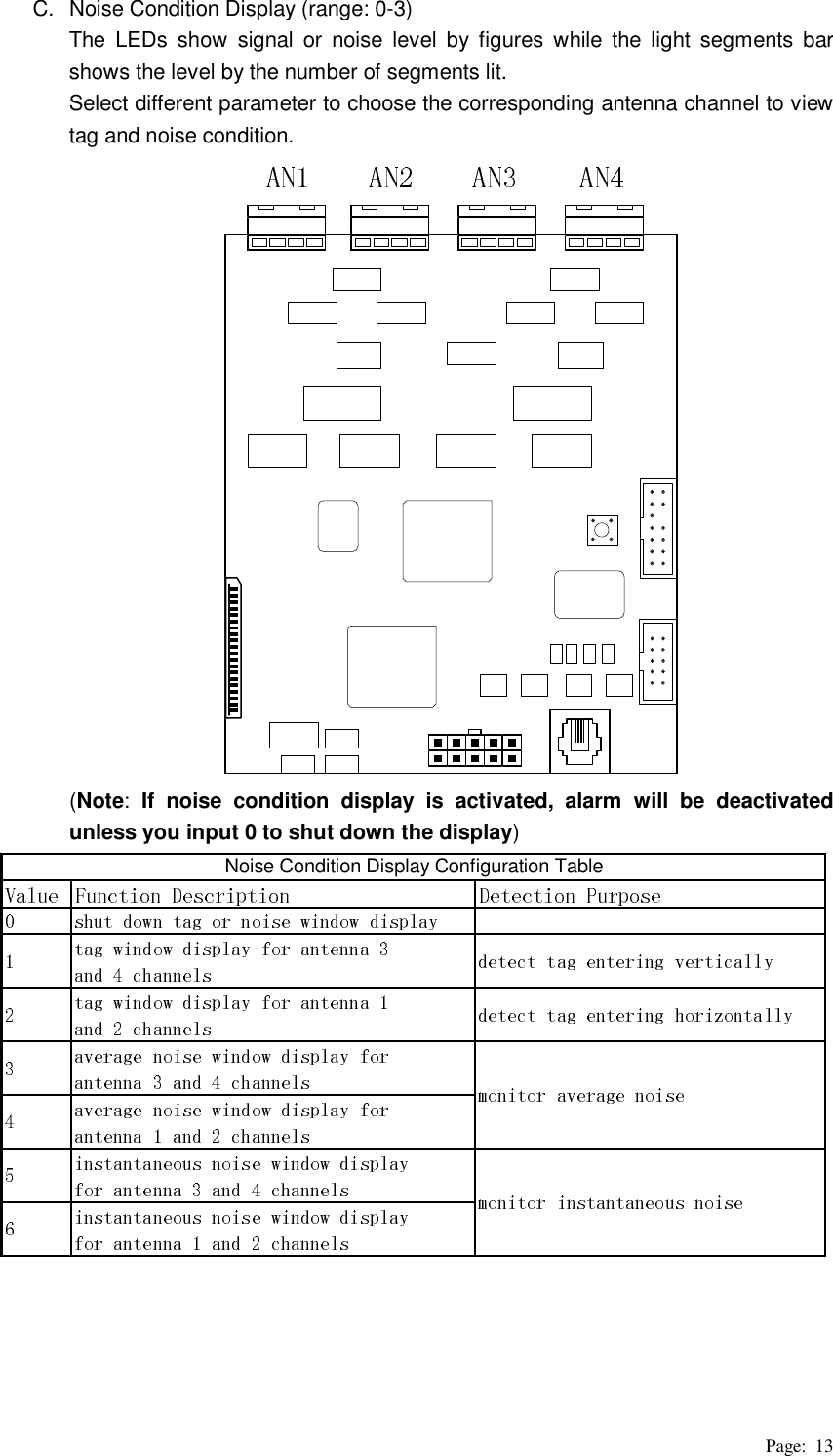
WG security MGSKG58 Electronic Article Surveillance System User Manual Overview
WG Security Products, Inc Electronic Article Surveillance System Overview
UserManual.wiki
>
WG security
>
MGSKG58 User Manual
User Manual
Navigation menu
Upload a User Manual
Namespaces
Wiki Guide
HTML
PDF
Info
Views
User Manual
Discussion / Help
Navigation

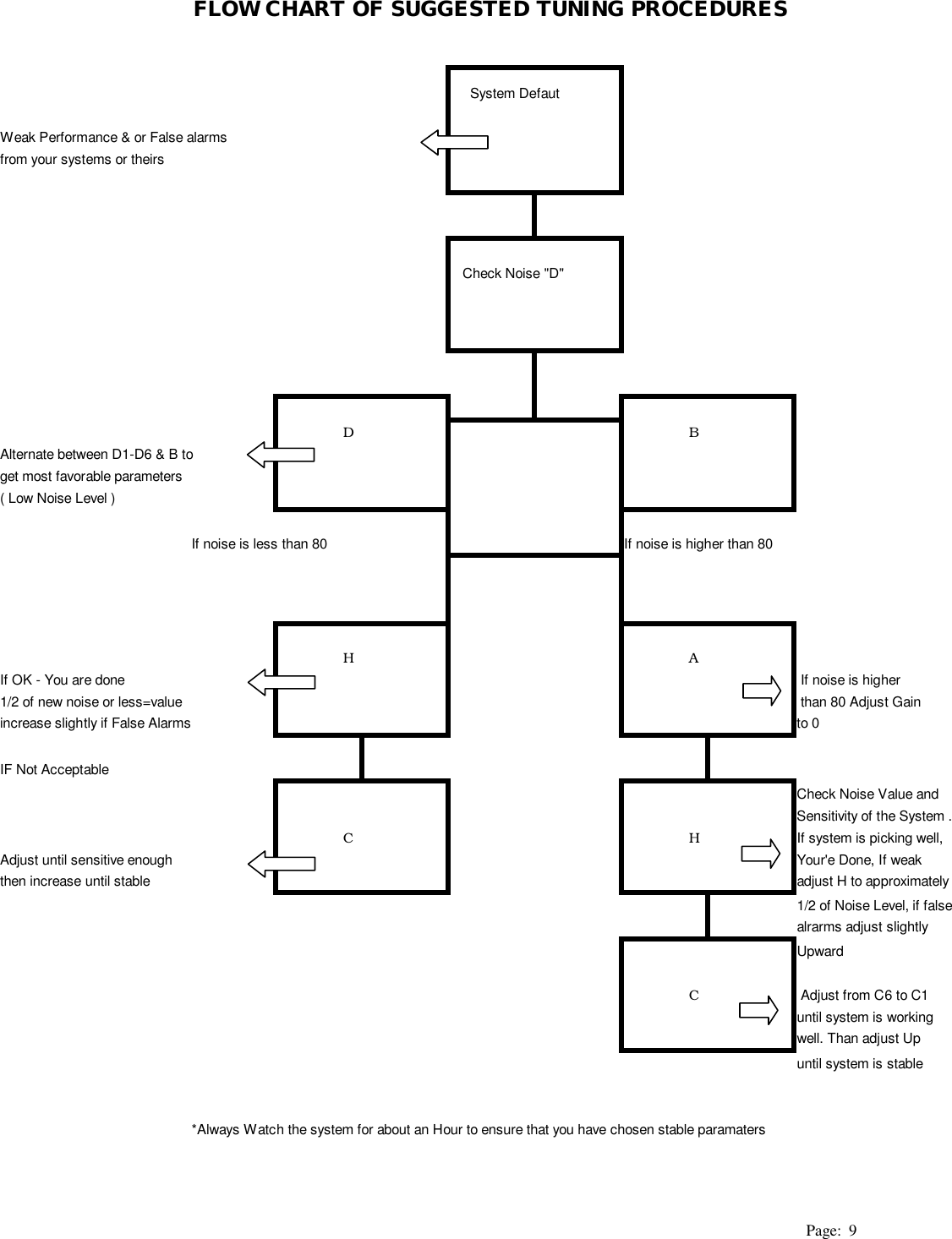
![Page: 8 Appendix (IR control keyboard function description) Default Parameters Table WGSPI Strongly recommends using the Self Tuning Mode when installing the system for the first time, please see [H] entry for instructions on how to operate this feature.](https://usermanual.wiki/WG-security/MGSKG58/User-Guide-272274-Page-10.png)