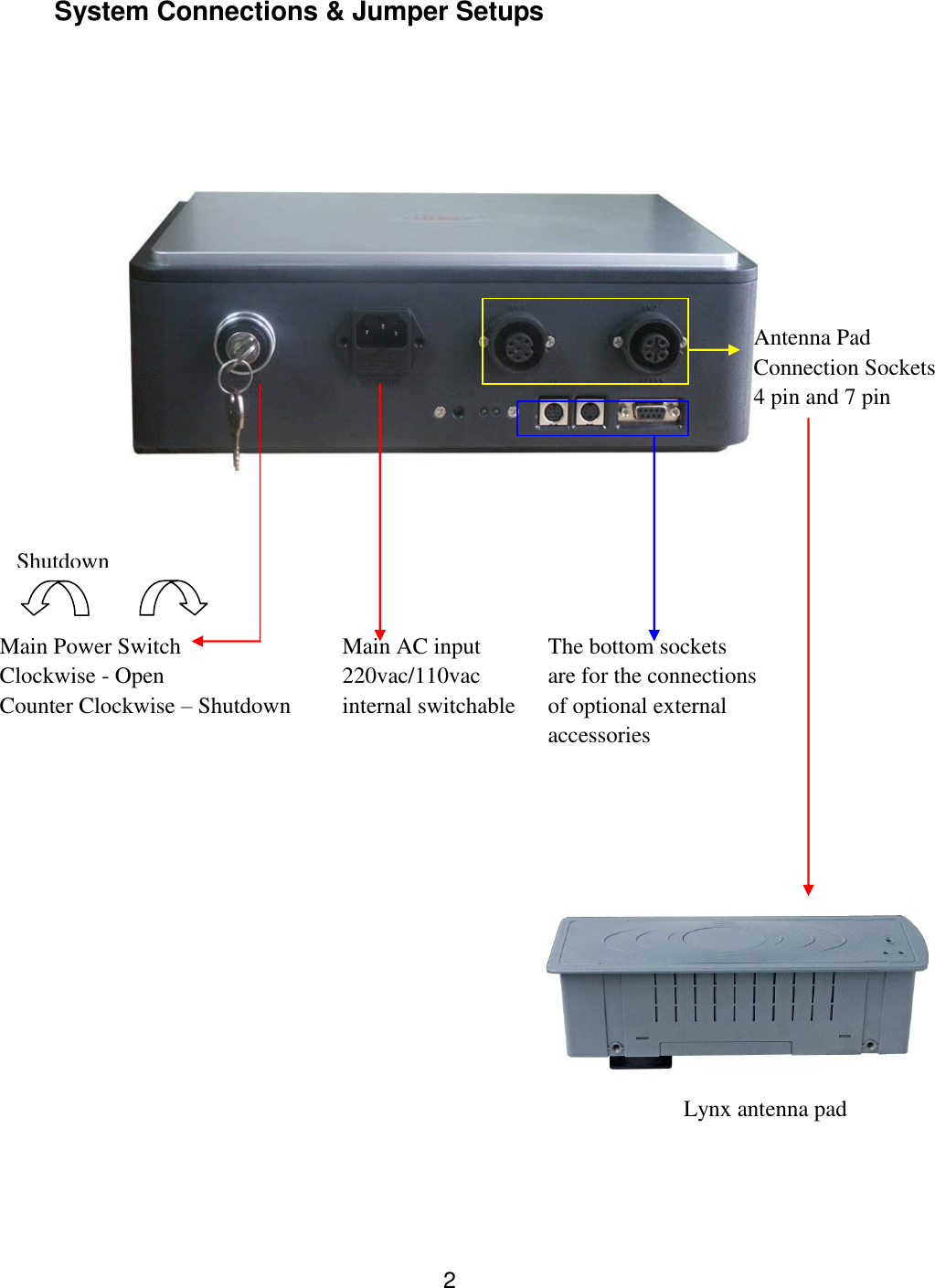
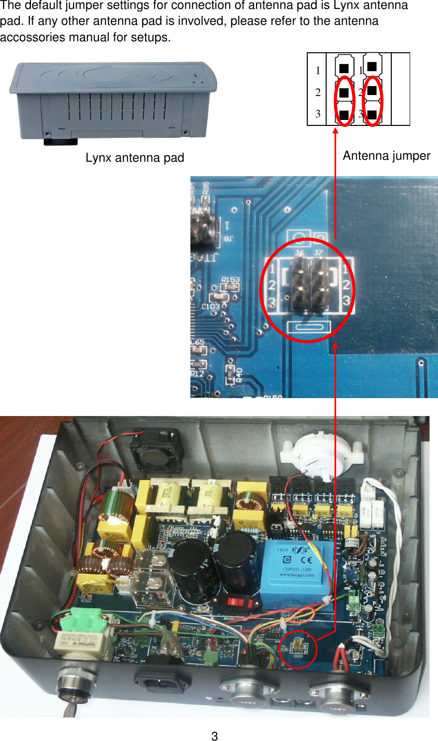
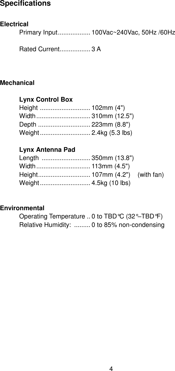
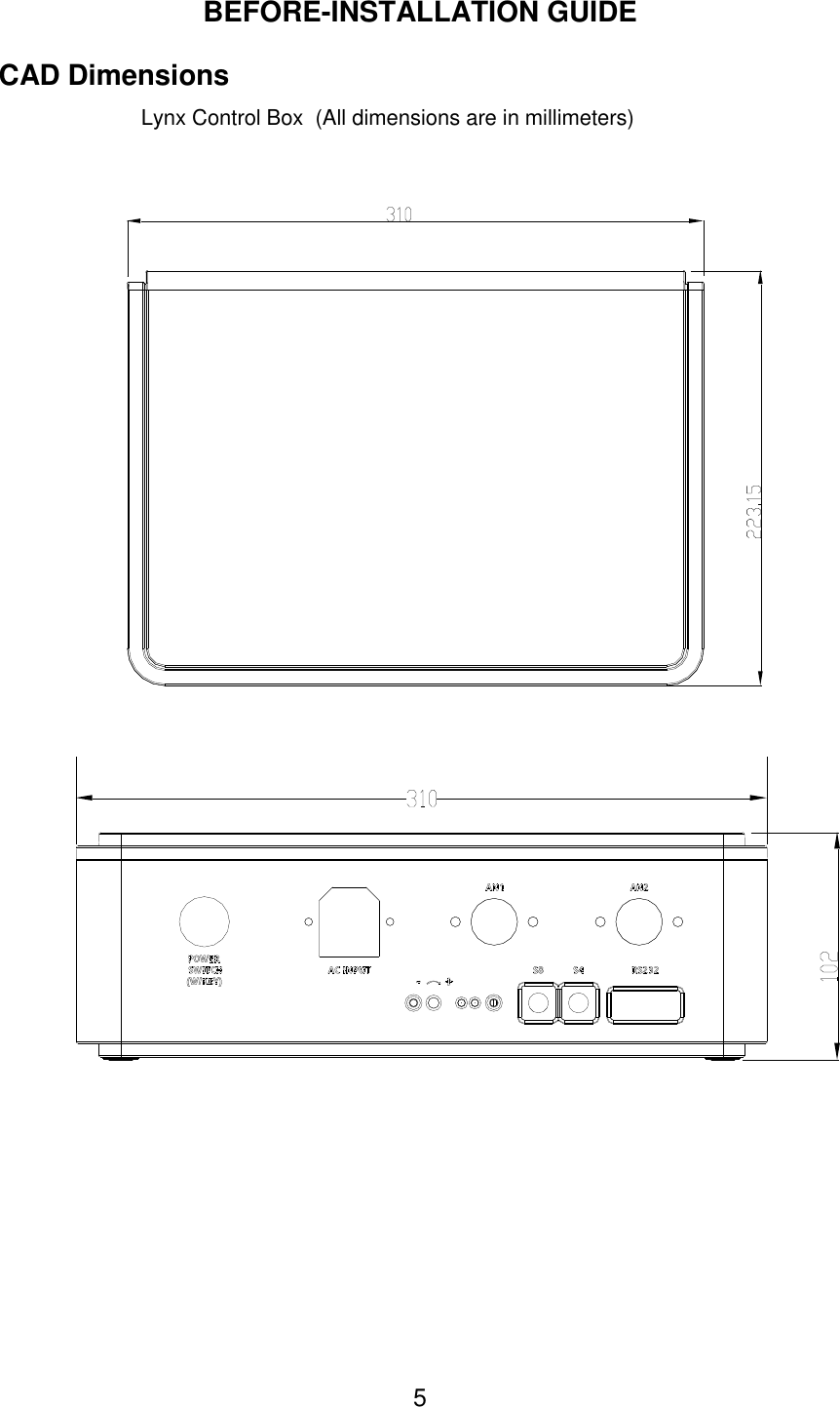
WG security WGLYNX Label Deactivator User Manual Overview
WG Security Products, Inc Label Deactivator Overview
UserManual.wiki
>
WG security
>
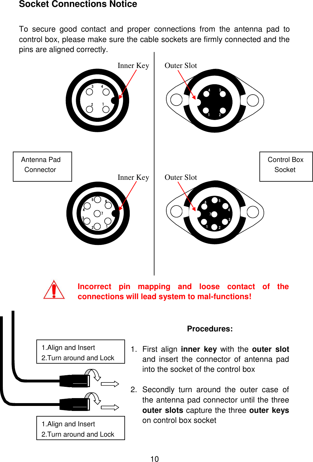
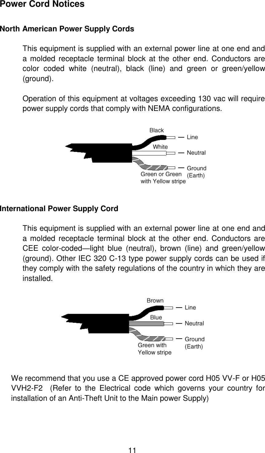
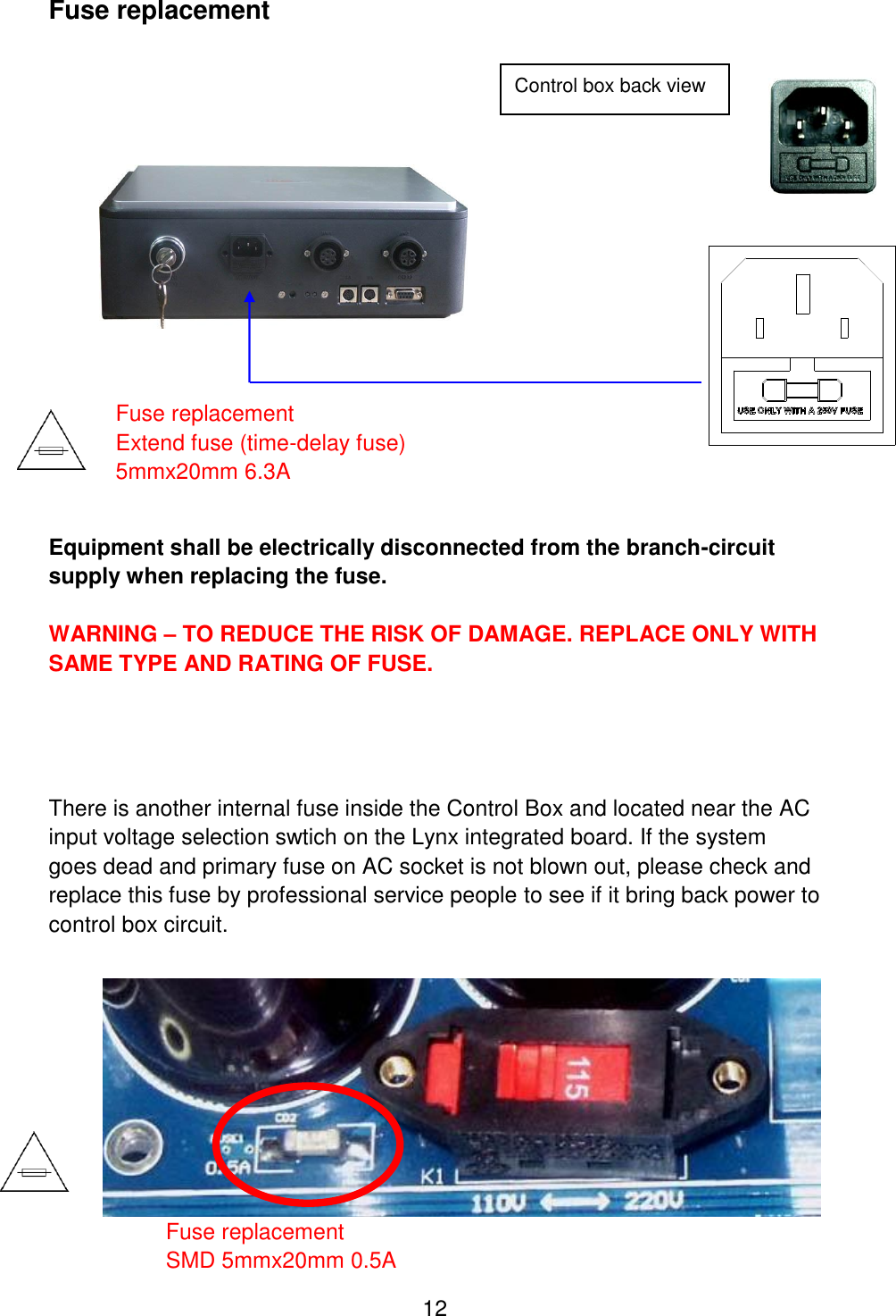
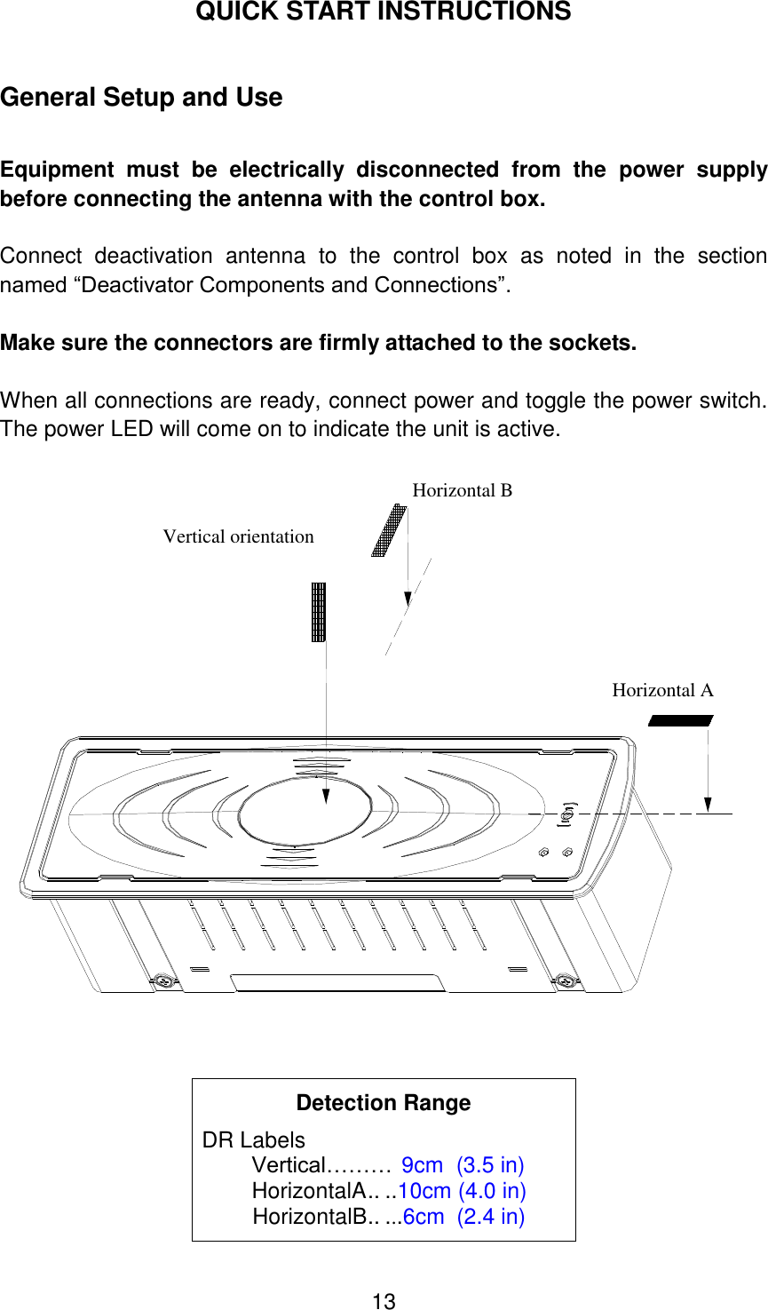
WGLYNX User Manual
User manual
Navigation menu
Upload a User Manual
Namespaces
Wiki Guide
HTML
PDF
Info
Views
User Manual
Discussion / Help
Navigation