WG security WGLYNX Label Deactivator User Manual Overview
WG Security Products, Inc Label Deactivator Overview
User manual

58kHz LynXTM
Control box
Instructions Manual
Version: 2008 July
Manual Part number: WG-LynX-IM July
(09150801)
WG SECURITY PRODUCTS INC.
3031 Tisch Way, Suite 602, San Jose, CA 95128 (USA)
Tel: 408-241-8000 ▪ Fax: 408-241-8082
For technical support in your country, visit our web site at www.wgspi.com.

TECHNICAL SUPPORT CONTACT INFORMATION
North America
South America
Carribean
Tel: 949-545-6005 x107
Fax: 949-545-6011
Email: service@wgspi.com
Rest of World
Tel: 408-241-8000
Fax: 408-241-8082
Email: support@wgspi.com
WARRANTY DISCLAIMER
WG Security Products Inc. makes no representation or
warranty with respect to the contents hereof and
specifically disclaims any implied warranties of
merchantability or fitness for any particular purpose.
Further, WG Security Products Inc. reserves the right
to revise this publication and make changes from time
to time in the content hereof without obligation of WG
Security Products Inc. to notify any person of such
revision or changes.
CRITICAL NOTE
As specified by FCC Regulations 15.21, any
changes or modifications not expressly approved
by the party responsible for compliance of this
equipment, will void the user’s permission and
authority to operate this equipment.
TABLE OF CONTENTS
OVERVIEW ..................................................................................................... 1
SYSTEM DESCRIPTION .................................................................................... 1
FEATURES ...................................................................................................... 1
SYSTEM CONNECTIONS & JUMPER SETUPS ...................................................... 2
SPECIFICATIONS ............................................................................................. 4
BEFORE-INSTALLATION GUIDE .................................................................. 5
CAD DIMENSIONS .......................................................................................... 5
CONTROL BOX INPUT POWER VOLTAGE CHECK ................................................ 7
INSTALLATION SITE POWER SUPPLY CHECK ...................................................... 7
INSTALLATION ............................................................................................... 8
PARTS LIST .................................................................................................... 8
DEACTIVATOR COMPONENTS AND CONNECTIONS .............................................. 9
SOCKET CONNECTIONS NOTICE ..................................................................... 10
POWER CORD NOTICES ................................................................................ 11
FUSE REPLACEMENT ..................................................................................... 12
QUICK START INSTRUCTIONS ................................................................... 13
GENERAL SETUP AND USE ............................................................................ 13
RECORDED MEDIA PRODUCTS DEACTIVATION .. ERROR! BOOKMARK NOT DEFINED.
1
OVERVIEW
System Description
Lynx is an advanced EAS label deactivator with highly integrated control box, providing
excellent deactivation reliability and high throughput. The Lynx can work with a series of
deactivation antenna pad. When working with different antennas pad, the deactivator can
adapt to different counter applications requiring different desktop space and performance,
offering great flexibility.
Features
Proximity Deactivation
The Lynx offers proximity deactivation, making it perfect for both source tagged
and retailer tagged merchandise.
Compact Size
The compact size of of Lynx antenna pad and the control box allows Lynx to
easily be integrated into a counter application.
Integrated Audible and Visual Notification.
Label deactivation notification is built into the Lynx.
External Control Accessible
Lynx includes external control access via RS-232 series port that connects to
POS machine, footswitch and external tuning hardware.
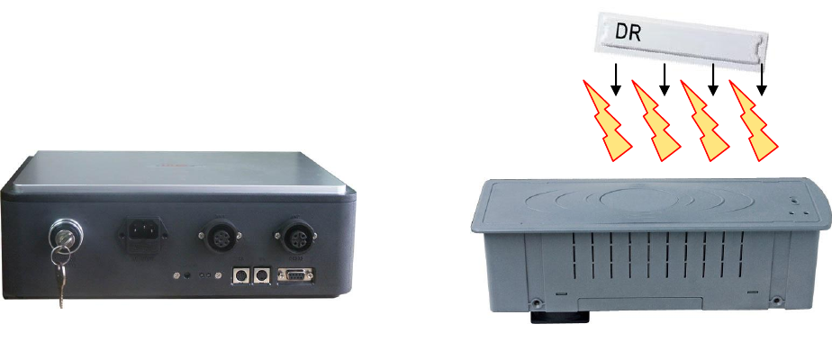
Double Resonant Labels for Deactivation
Lynx Control Box
Lynx Deactivation Pad
De-Gauss Field

2
System Connections & Jumper Setups
Main Power Switch
Clockwise - Open
Counter Clockwise – Shutdown
Main AC input
220vac/110vac
internal switchable
Antenna Pad
Connection Sockets
4 pin and 7 pin
Sockets
The bottom sockets
are for the connections
of optional external
accessories
Shutdown
Open
Lynx antenna pad
3
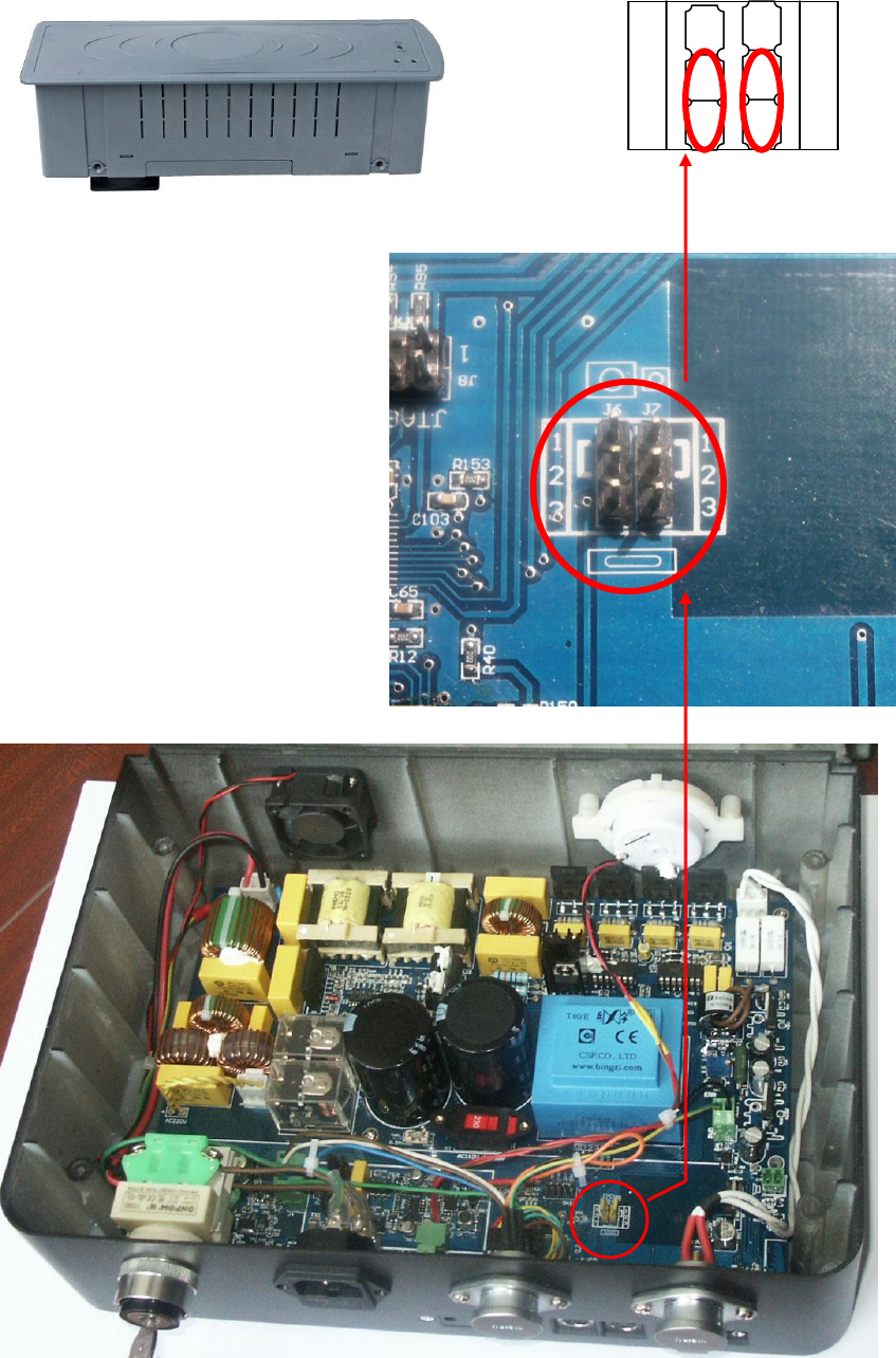
The default jumper settings for connection of antenna pad is Lynx antenna
pad. If any other antenna pad is involved, please refer to the antenna
accossories manual for setups.
Lynx antenna pad
1 1
2 2
3 3
■
■
■
■
■
■
Antenna jumper
4
Specifications
Electrical
Primary Input .................. 100Vac~240Vac, 50Hz /60Hz
Rated Current ................. 3 A
Ac Operating Phase...........0°, 120°, or 240°
Mechanical
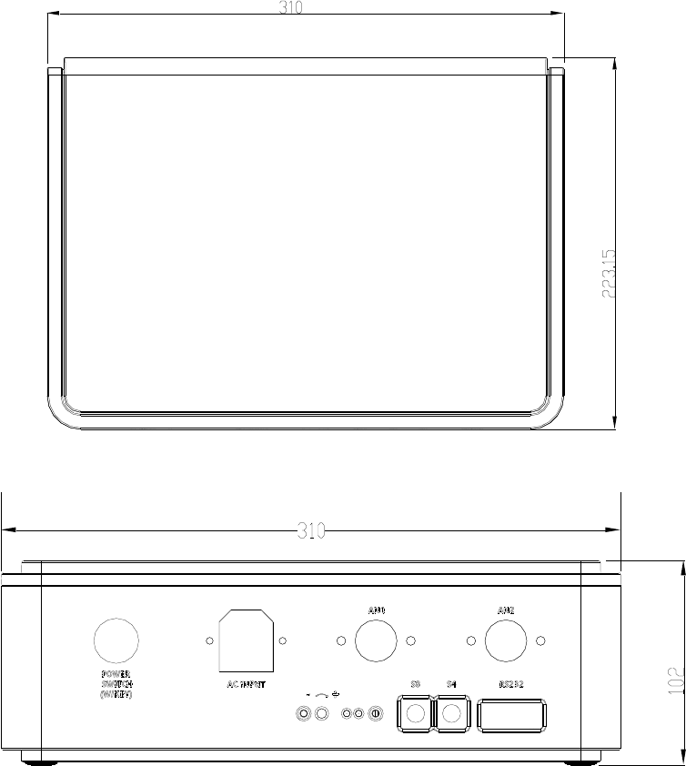
Lynx Control Box
Height ............................ 102mm (4")
Width .............................. 310mm (12.5")
Depth ............................. 223mm (8.8")
Weight ............................ 2.4kg (5.3 lbs)
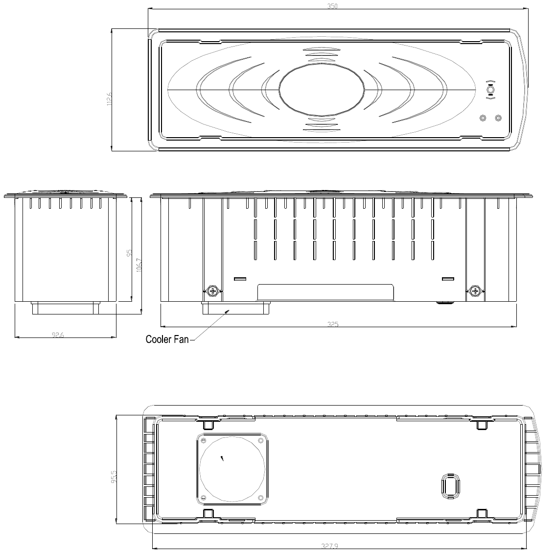
Lynx Antenna Pad
Length ........................... 350mm (13.8")
Width .............................. 113mm (4.5")
Height ............................. 107mm (4.2") (with fan)
Weight ............................ 4.5kg (10 lbs)
Environmental
Operating Temperature .. 0 to TBD°C (32°–TBD°F)
Relative Humidity: ......... 0 to 85% non-condensing
5
BEFORE-INSTALLATION GUIDE
CAD Dimensions
Lynx Control Box (All dimensions are in millimeters)
6
Lynx Antenna (All dimensions are in millimeters)
7
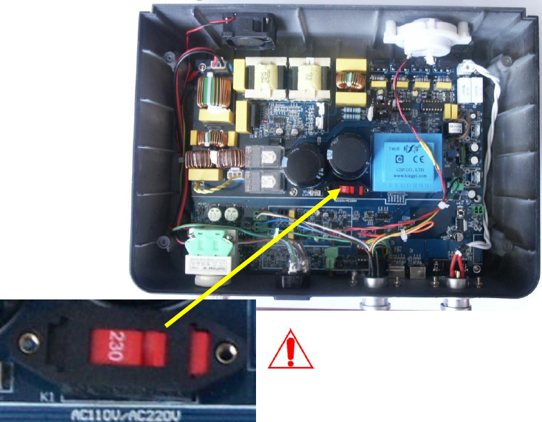
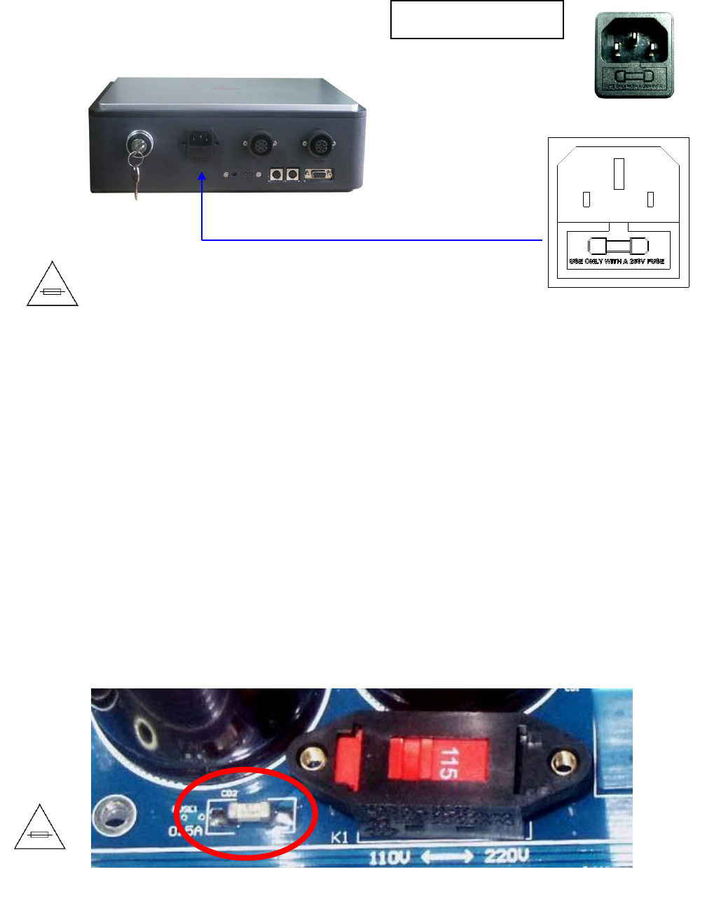
Control Box Input Power Voltage Check
Installation Site Power Supply Check
IT’S RECOMMENDED TO HAVE ALL CONTROL BOX ON THE SAME
POWER PHASE,otherwise you need to adjust B sync value step by step
to find a best position to sync different control box connected to power
source with difference phase.
IT’S RECOMMENDED TO HAVE ENOUGH CURRENT SUPPLY FOR
DEACTIVATORS IF THERE ARE MULTIPLE DEACTIVATORS SHARE
ONE POWER SUPPLY. The rated current for Lynx is 3A but the
suggested current draw for one FastPad is 7-8A for better performance, so
a 15 amp power box will better serve 2 deactivators instead of 3 or more.
IT’S RECOMMENDED TO HAVE GOOD GROUNDING FOR POWER
SUPPLY OF DEACTIVATORS. (Some time the poor grounding and high
noise from power supply will decrease the sensitivity or detection range.)
The number on the switch shows which AC input the
system is set to.
In North America, please place the switch at 115;
While in Europe, please place the switch at 230.

8
INSTALLATION
Parts List
Part Name
Order Number
Lynx Control Box
Lynx Antenna
Foot Switch
External Alarm and Lock
WG LynX-CB
WG LynX-AT
Lock Key (2)
Foot Switch
(Optional)
External Alarm
and Lock
(Optional)
Control box (1)
9
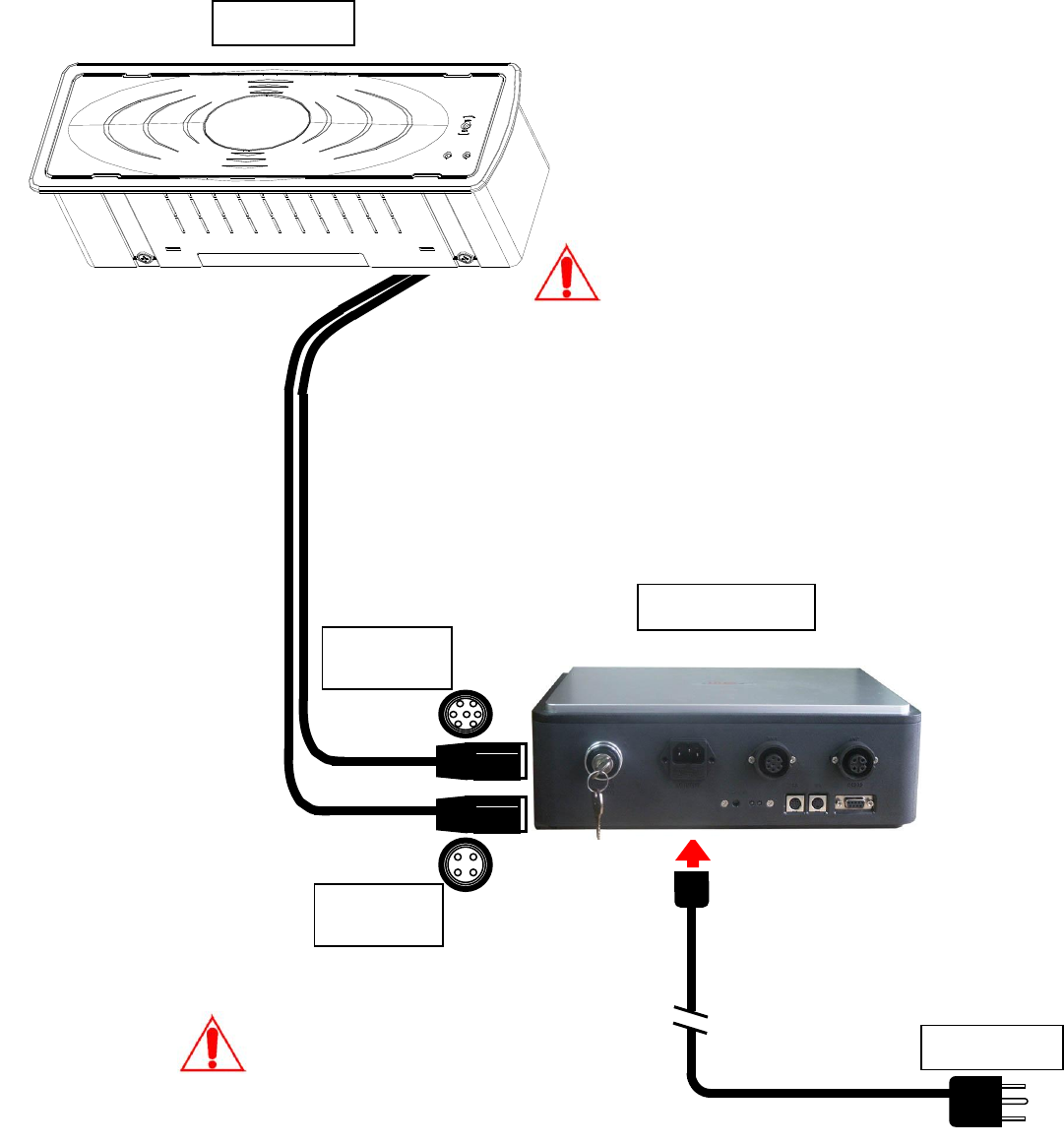
Deactivator Components and Connections
As shown in Figure 1, the deactivator consists of a detect/deactivator antenna
pad, power and control box. The cables used and connections are shown in
the following diagram. The antenna pad can be installed flush to the counter
with the flush mount kit.
Antenna
Control Box
7-pin
Connector
4-pin
Connector
Power Plug
Always match the antenna type (see page
3) with control box internal jumper setups
before connecting them; make sure they
are matched.
The control box hardware is identical to all
antennas but their internal jumper setups
are different and cannot be mixed.
HIGH VOLTAGE – HANDLE WITH
CARE!
Equipment must be electrically
disconnected from the branch-circuit
supply when connecting the antenna
with the control box.
10
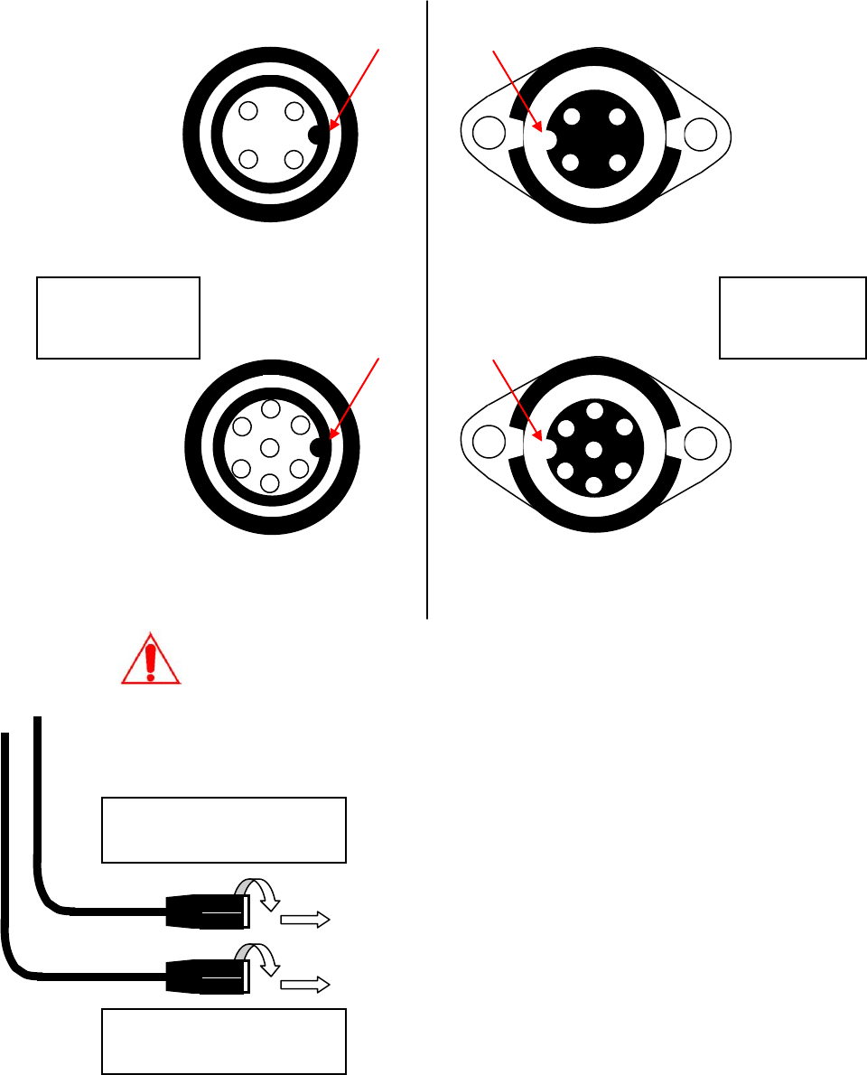
Socket Connections Notice
To secure good contact and proper connections from the antenna pad to
control box, please make sure the cable sockets are firmly connected and the
pins are aligned correctly.
1.Align and Insert
2.Turn around and Lock
Procedures:
1. First align inner key with the outer slot
and insert the connector of antenna pad
into the socket of the control box
2. Secondly turn around the outer case of
the antenna pad connector until the three
outer slots capture the three outer keys
on control box socket
Control Box
Socket
3
4
1
2
5
3
2
4
1
Inner Key
Antenna Pad
Connector
Incorrect pin mapping and loose contact of the
connections will lead system to mal-functions!
1
2
3
4
Outer Slot
Outer Slot
7
1
2
3
4
5
6
6
7
Inner Key
1.Align and Insert
2.Turn around and Lock
11
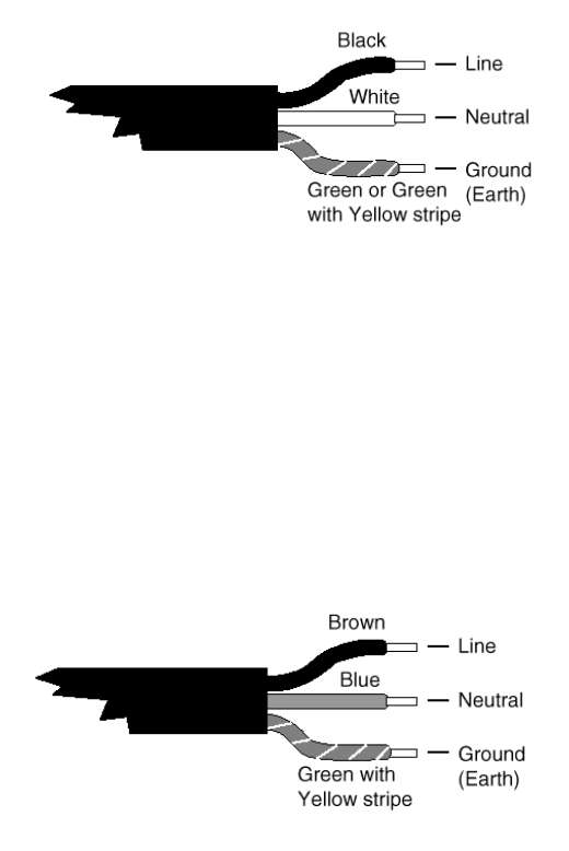
Power Cord Notices
North American Power Supply Cords
This equipment is supplied with an external power line at one end and
a molded receptacle terminal block at the other end. Conductors are
color coded white (neutral), black (line) and green or green/yellow
(ground).
Operation of this equipment at voltages exceeding 130 vac will require
power supply cords that comply with NEMA configurations.
International Power Supply Cord
This equipment is supplied with an external power line at one end and
a molded receptacle terminal block at the other end. Conductors are
CEE color-coded—light blue (neutral), brown (line) and green/yellow
(ground). Other IEC 320 C-13 type power supply cords can be used if
they comply with the safety regulations of the country in which they are
installed.
We recommend that you use a CE approved power cord H05 VV-F or H05
VVH2-F2 (Refer to the Electrical code which governs your country for
installation of an Anti-Theft Unit to the Main power Supply)
12
Fuse replacement
Equipment shall be electrically disconnected from the branch-circuit
supply when replacing the fuse.
WARNING – TO REDUCE THE RISK OF DAMAGE. REPLACE ONLY WITH
SAME TYPE AND RATING OF FUSE.
There is another internal fuse inside the Control Box and located near the AC
input voltage selection swtich on the Lynx integrated board. If the system
goes dead and primary fuse on AC socket is not blown out, please check and
replace this fuse by professional service people to see if it bring back power to
control box circuit.
Fuse replacement
Extend fuse (time-delay fuse)
5mmx20mm 6.3A
Control box back view
Fuse replacement
SMD 5mmx20mm 0.5A
13
QUICK START INSTRUCTIONS
General Setup and Use
Equipment must be electrically disconnected from the power supply
before connecting the antenna with the control box.
Connect deactivation antenna to the control box as noted in the section
named ―Deactivator Components and Connections‖.
Make sure the connectors are firmly attached to the sockets.
When all connections are ready, connect power and toggle the power switch.
The power LED will come on to indicate the unit is active.
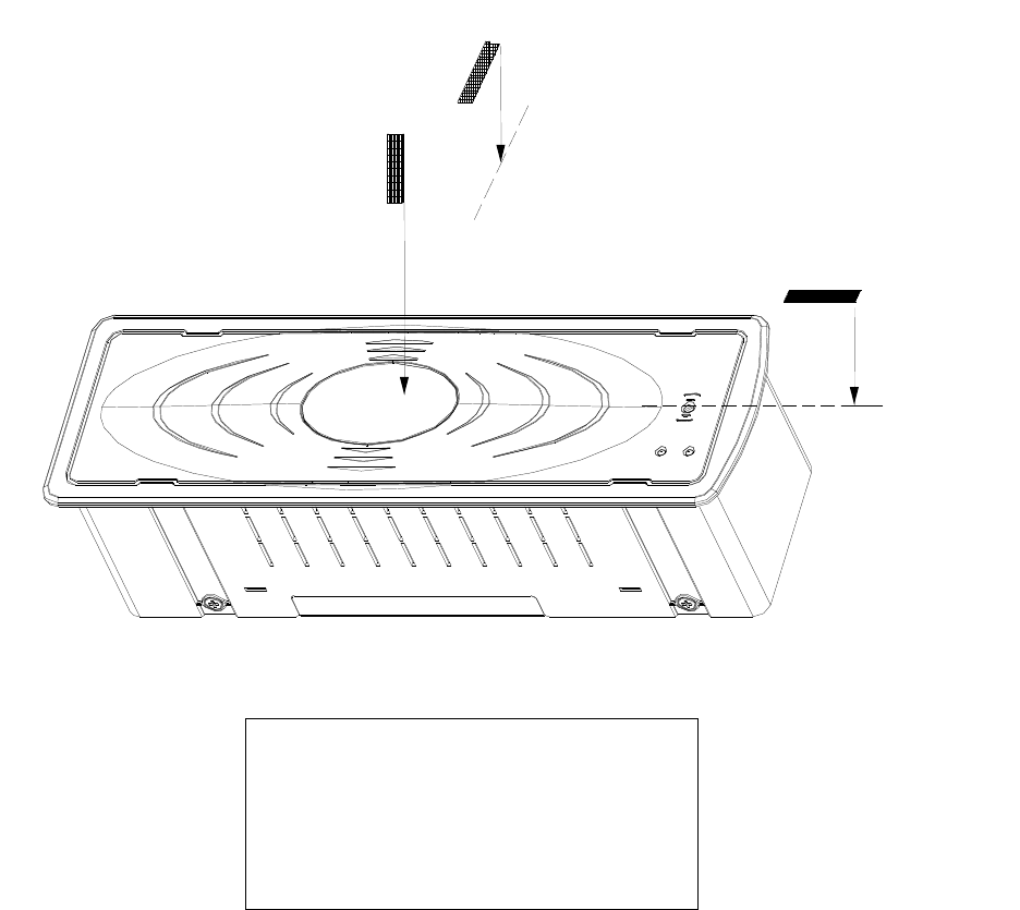
Detection Range
DR Labels
Vertical……… 9cm (3.5 in)
HorizontalA .. ..10cm (4.0 in)
HorizontalB .. ...6cm (2.4 in)
Horizontal B
Horizontal A
Vertical orientation

14
Vertical Deactivation Range
DR Labels
Vertical…….…..5cm (2 in)
HorizontalA .. ....3cm (1.2 in)
HorizontalB .... ...4cm (1.6 in)
Horizontal A
Horizontal A 3cm
Vertical orientation
5cm
Horizontal B
4cm
Horizontal A peak position 9cm