WG security WGBTLFG Floor Guard BTL System User Manual
WG Security Products, Inc Floor Guard BTL System Users Manual
User Manual

58Khz
Floor Guard
With Control Box
Installation Manual
Version: 2012
Manual Part Number: WG BTLFG IM
(120203A)
WG SECURITY PRODUCTS INC.
3031 Tisch Way, Suite 602, San Jose, CA 95128 (USA)
http://www.wgspi.com

This equipment has been tested and found to comply with the limits for a class B
digital device, pursuant to Part 15 of the Federal Communications Commission (FCC)
rules. These limits are designed to provide reasonable protection against harmful
interference in a residential installation. This equipment generates, uses, and can
radiate radio frequency energy and, if not installed and used in accordance with the
instructions, may cause harmful interference to radio communications. However,
there is no guarantee that interference will not occur in a particular installation. If this
equipment does cause harmful interference to radio or television reception, which
can be determined by turning the equipment off and on, the user is encouraged to try
to correct the interference by one or more of the following measures:
‧ Reorient or relocate the receiving antenna.
‧ Increase the separation between the equipment and receiver.
‧ Connect the equipment into an outlet on a circuit different from that to which the
receiver is connected.
‧ Consult the dealer or an experienced radio/TV technician for help.
The use of a shielded-type power cord is required in order to meet FCC emission
limits and to prevent interference to the nearby radio and television reception. It is
essential that only the supplied power cord be used. Use only shielded cables to
connect I/O devices to this equipment. You are cautioned that changes or
modifications not expressly approved by the party responsible for compliance could
void your authority to operate the equipment.
Note:
Any changes or modifications not expressly approved by the grantee of this device
could void the user's authority to operate the equipment.
RF exposure warning
This equipment complies with FCC radiation exposure limits set forth for an
uncontrolled environment.This equipment must be installed and operated in
accordance with provided instructions and the antenna(s) used for this transmitter
WARRANTY DISCLAIMER
WG Security Products Inc. makes no representation or
warranty with respect to the contents hereof and
specifically disclaims any implied warranties of
merchantability or fitness for any particular purpose.
Further, WG Security Products Inc. reserves the right
to revise this publication and make changes from time
to time in the content hereof without obligation of WG
Security Products Inc. to notify any person of such
revision or changes.
FCC ID: P9I-WGBTLFG
“This device complies with Part 15 of the FCC Rules. Operation is
subject to the following two conditions: (1) This device may not cause
harmful interference, and (2) This device must accept any interference
received, including interference that may cause undesired operation.”

Technical Support Contact Information
North America
South America
Tel: 949-545-6005
Toll Free: 888-633-5095
Fax: 949-545-6011
Email: service@wgspi.com
Rest of World
Tel: 4+49 8654 7715-21
Fax: 4+49 8654 7715-21
Email: support-ROW@wgspi.com
CRITICAL NOTE
As specified by FCC Regulations 15.21, any
changes or modifications not expressly approved
by the party responsible for compliance of this
equipment, will void the user’s permission and
authority to operate this equipment.
TABLE OF CONTENTS
OVERVIEW ............................................................................................................................... 5
SYSTEM OVERVIEW ................................................................................................................. 5
SYSTEM CONFIGURATION......................................................................................................... 2
FLOOR GUARD FEATURES & BENEFITS..................................................................................... 2
SPECIFICATIONS...................................................................................................................... 3
PRE-INSTALLATION INFORMATION..................................................................................... 4
FLOOR GUARD CONTROL UNIT DIMENSIONS ............................................................................. 4
FLOOR GUARD ANTENNA DIMENSIONS ..................................................................................... 5
INSTALLATION ........................................................................................................................ 6
PARTS LIST –FLOOR GUARD OVERALL SYSTEM ........................................................................ 6
QUICK START FOR SYSTEM CONNECTIONS ............................................................................... 7
INTERIOR CABLE AND CONNECTOR CONNECTIONS .................................................................... 8
POWER CORD NOTICES ........................................................................................................... 9
North American Power Supply Cords............................................................................... 9
International Power Supply Cord...................................................................................... 9
FUSE REPLACEMENT INFORMATION ........................................................................................ 10
OVERVIEW
System Overview
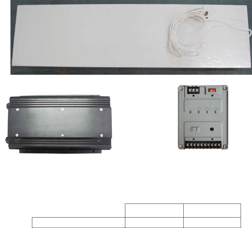
Floor-Guard systems consist of one sealed floor antenna, a 58khz control unit and a smart
power supply unit (WG SPS-24). The control unit provides all the control functions for the
transceiver, including tag detection and alarm notification. The floor antenna is fully sealed
and water-proof and can be buried in concrete or cement floor.
Detection Range ( up from floor )
Europe USA
Super Pencil Tag 0.9 m 3 ft
Floor Guard Control Unit
WG- 24vac Stepdown Transformer
WG SPS-24
Floor Antenna
( with ferrite antennas )
WG-
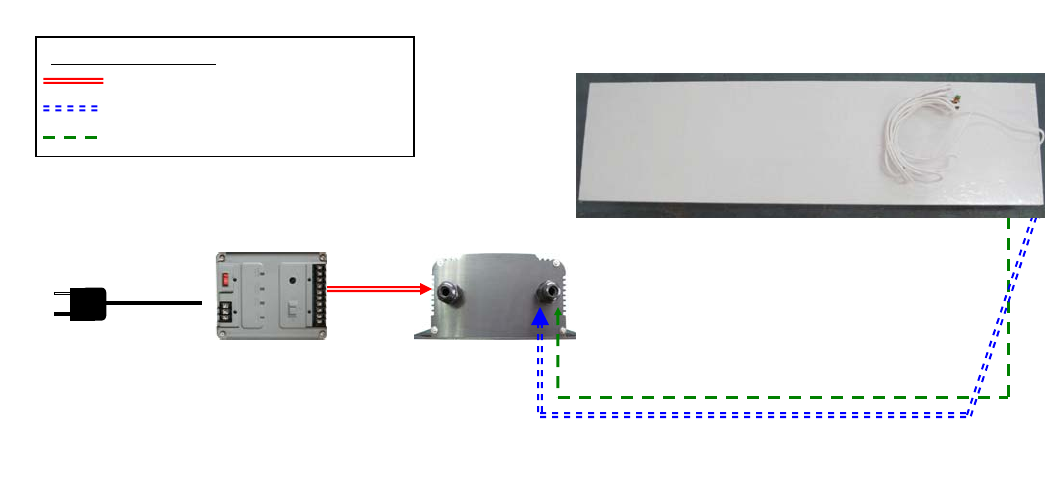
System Configuration
The PLCU controls the transceiver through the TX control cable. All detection information is
received through the RX cable. The Transformer power box powers the PLCU and
transceiver through two separate cables. The following diagram illustrates the connections.
Floor Guard Features & Benefits
• Ultra Thin Antenna Design
The ultra thin antenna less than 1 inch thickness can make the floor antenna easily
buried into the concrete floor in many multi floors shopping mall environment.
• Digital Signal Processing
The Premier Guard applies the latest and most advanced DSP technology for anti-
theft solutions, virtually eliminating false alarms while maintaining considerable
detection range.
• Integrated Audible and Visual Notification
Alarm notification is built into the Premier Guard on both the pedestal and controller.
Floor Guard
Buried antenna
6
p
cable
Control Unit
Ferrite AN1: brown and red wires
Ferrite AN2: orange and yellow wires
Connections Legend
WG SPS-24 6p Cable
TX Loop and Figure8 Driving Cable
RX Ferrite Rod Signal
Figure8 AN: blue and green wires
Loop AN: white and black wires
WGSPS
-
24
110/220vac
Maximum Connection Length:4 meters

Specifications
Electrical
Primary Input
(Stepdown Transformer) 230/115 ±10% @50/60Hz (Input)
26vac @ 4A (Output)
Pedestal Input 26vac @50/60Hz
Control Unit Input 26vac @50/60Hz
Control Unit Rated Current 1.8A @ 26vac
(The rated current data is given at driving 1500X400mm Floor Guard Antenna)
Transmitter Output 1.6ms Burst
Operating Frequency 58Khz
Mechanical
Floor Guard Antenna
Length 1500mm (59”)
Width 400mm (15.7”)
Thickness 25mm (1.0”)
Weight 15Kg (33.1lbs)
Floor Guard Control Unit
Length 302mm (11.9”))
Width 210mm (8.3”)
Height 97mm (3.8”)
Weight 2.8Kg (6.2lbs)
WG SPS-24 Smart Power Supply
Height 80mm ( 3.15” )
Width 110mm ( 4.33” )
Thickness 140mm ( 5.5” )
Weight 3 Kg ( 6.6 lbs)
Environmental
Maximum Operating
Temperature 45 °C (113°F)
Relative Humidity 0 to 85% non-condensing
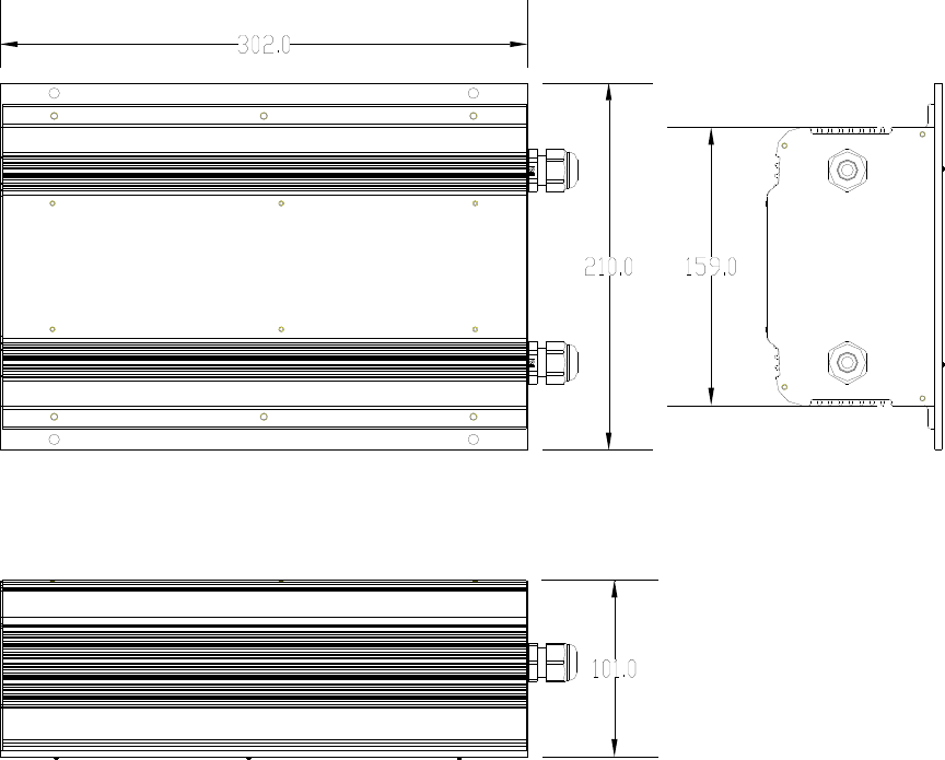
PRE-INSTALLATION INFORMATION
Floor Guard Control Unit Dimensions
(All dimensions are in millimeters)
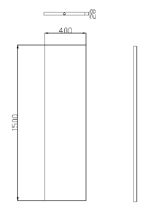
Floor Guard Antenna Dimensions
(All dimensions are in millimeters)
INSTALLATION
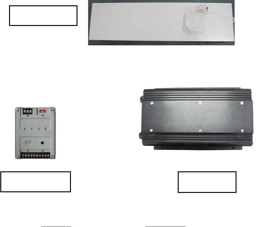
Parts List –Floor Guard Overall System
Part Name Order Number
1. Floor Guard Antenna WG
2. Floor Guard Control Unit WG
3. 24vac Smart Power Supply WG SPS-24
4. Digitool Tuning Software
Note: Digitool Tuning Software is provided upon
separate order
Control Box
WG
24vac Transformer
WG SPS-24
Floor Antenna
WG-

Quick Start for System Connections
A Floor Guard system consists of a smart power supply (WG SPS-24), a Floor Guard Control
Unit and a Floor Antenna.
The smart power supply has a 6-pins 24vac outputs that can only power the Floor Guard
Control Unit through 24vac and also communicate with the control unit for some tuning control
and remote alarm display features.
The PLCU is powered and controlled by the WG SPS-24 power supply unit. Also the control
unit has an 8-conductors cable with two 4pins connectors assembled on one end to connect
to the Floor Guard Control Unit transceiver board. One of the connectors is 4-pins connector
for TX transmitting signals from the Control Unit to drive a loop antenna coil and a figure8
antenna coil in Floor Guard antenna. The other connector is a 4-pins connector for RX signals
from the Control Unit to receive signals from Floor Guard ferrite antennas.
Notice: Both the TX and RX cables has wire orders that follow the pin and wire color
mapping and can not be transpose with the order.
Additional installation procedures are shown in greater detail in the following sections.
Floor Guard
Buried antenna
6
p
cable
Control Unit
Ferrite AN1: brown and red wires
Ferrite AN2: orange and yellow wires
Connections Legend
WG SPS-24 6p Cable
TX Loop and Figure8 Driving Cable
RX Ferrite Rod Signal
Figure8 AN: blue and green wires
Loop AN: white and black wires
WGSPS
-
24
110/220vac
Maximum Connection Length:4 meters
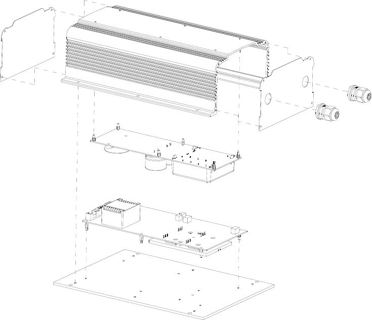
Interior Cable and Connector Connections
For interior Cable connection, user should open the control unit case, and take the two
PC boards –socket connection board and the BTL AM board (ver4.1) out for access to
the sockets for connection to FloorGuard antenna and the WG SPS-24 power supplies.
Cable outlet for
WG SPS-24
Cable outlet for
Floor antenna
Socket Connection Board
BTL AM Board (ver4.1)
Control Unit
Aluminum Chassis
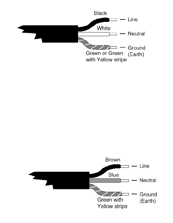
Power Cord Notices
North American Power Supply Cords
This equipment is supplied with an external power line at one end and a molded
receptacle terminal block at the other end. Conductors are color coded white (neutral),
black (line) and green or green/yellow (ground).
Operation of this equipment at voltages exceeding 130vac will require power supply
cords that comply with NEMA configurations.
International Power Supply Cord
This equipment is supplied with an external power line at one end and a molded
receptacle terminal block at the other end. Conductors are CEE color-coded—light
blue (neutral), brown (line) and green/yellow (ground). Other IEC 320 C-13 type
power supply cords can be used if they comply with the safety regulations of the
country in which they are installed.
We recommend that you use a CE approved power cord H05 VV-F or H05 VVH2-F2
(Refer to the electrical code which governs your country for installation of an Anti-Theft
Unit to the main power supply)
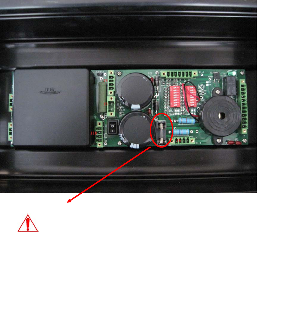
Fuse Replacement Information
The fuse holder is located on the control box inside Socket PC board.
WARNING – TO REDUCE THE RISK OF DAMAGE; REPLACE ONLY WITH
THE SAME FUSE TYPE AND RATING.
1. Equipment shall be electrically
disconnected from the branch-
circuit supply when replacing the
fuse.
2. Remove the fuse holder with a
screwdriver, rotating it in a
counterclockwise direction.
3. Replace the fuse in accordance
with the specification noted
below.
Fuse Replacement:
Extended Fuse (Time-Delay Fuse)
5mm x 20mm 24vac @ T3.15A/250V