WG security WGMG58 58kHz Electronic Article Surveillance System User Manual 2002
WG Security Products, Inc 58kHz Electronic Article Surveillance System 2002
User Manual

58KHz Mono-Guard Transceiver System Quick Start
58kHz MONO-GUARDTM
INSTALLATION
MANUAL
WG SECURITY PRODUCT INC.
161 San Lazaro Ave. Sunnyvale, CA 94086 USA
Tel: 1-877-494-2288 (Toll Free) 1-408-530-8070 Fax: 1-408-530-8074
Website: www.wgspi.com E-mail:info@wgspi.com

58KHz Mono-Guard Transceiver System Quick Start
Overview
1. System Description
Mono-Guard is a single pedestal transceiver Electronic Article Surveillance system
that detects 58KHz tags four feet either side of the pedestal. This system is plug and
play, which eliminates the need for expensive technicians during installation.
The Mono-Guard is software driven EAS system that works in combination with any
58KHz tag and label. The system’s transceiver listens for the unique signal that any
58KHz tag produces, and the sequence produced is then verified and multiplied in a
fraction of a second.
Technical DataEurope United States
Height 1470mm 58"
Width 440mm 15.5"
Depth 100mm 3.5"
Weight 10Kg 22lbs
Power 200-220vac 110vac
Operating Frequency 58kHz 58kHz
Maximum Tag Detection 2.2 meters 8 feet
IMPORTANT NOTICE:
To turn off the unit please unplug it from the main power source.
When installing this unit it is important that you follow the National Electrical Code
that governs your country.

58KHz Mono-Guard Transceiver System Quick Start
Digital Signal Processing
The Mono-GuardTM system applies the latest and most technically advanced
DSP technologies to address antitheft problems. It minimizes false alarms while
maintaining considerable detection range.
Self-Tuning Electronics
Other manufacturers need professional technicians to tune the system to
ensure proper functioning. But once the environment condition changes, the
systems best working position changes and requires tuning again. The
Mono-GuardTM system, benefiting from its fully digital electronics, constantly
detects the environment & automatically adapts to any changes. It will
always operate at its optimum performance from the beginning.
Software Driven
The Mono-GuardTM is fully digital software driven system, which allows
unprecedented flexibility especially in later versions.
Applications
This type of installation also
consists of a single Mono-
Guard
post while with coverage of a 6 foot
wide opening. The post is mounted
in the middle of the door with a 4
feet maximum detection on either
side. The Mono-
Guard can be
installed close
to a metal door or
frame with out decreasing the
detection range, how-
ever we do
recommend that the when using a
neon light, the system should be
installed 12 ft away, if this is not
possible you can install our noise
shield over the transformer to
eliminate this problem.

58KHz Mono-Guard Transceiver System Quick Start
This type of installation also
consists of a single Mono-
Guard
post while with coverage of a 6 foot
wide opening. The post is mounted
in the middle of the door with a 4
feet maximum detection on either
side. The Mono-
Guard can be
instal
led close to a metal door or
frame with out decreasing the
detection range, how-
ever we do
recommend that the when using a
neon light, the system should be
installed 12 ft away, if this is not
possible you can install our noise
shield over the transformer
to
eliminate this problem.
This type of installation consists
of one master and one slave
Mono-
Guard system with one
interconnection from slave to the
master. The gates are mounted
on both sides of the opening and
can cover a maximum range of
8 feet between the pedestals.
The Mono-
Guard can be installed
close to a metal door or frame
with out decreasing the detection
range, how-
ever we do
recommend that the when using
a neon light, the system should
be installed 12 ft away. If this is
not possible you ca
n install our
noise shield over the transformer
to eliminate this problem.

58KHz Mono-Guard Transceiver System Quick Start
Installation Procedures
Parts List
This type of installation consists of one master Mono-
Guard system and two slaves
with the master in middle and the slaves at the ends. Every gate-to-
gate distance is
both 8 feet
maximum; the three gates will cover a maximum distance of 16 feet.
Each slave post will be connected to master post.
The Mono-
Guard can be installed close to a metal door or frame with out
decreasing the detection range, how-ever we do recommend that the
when using a
neon light, the system should be installed 12 ft away, if this is not possible you can
install our noise shield over the transformer to eliminate this problem.
Base (1) Inflationary Spiral (6) Tools (2 sets)

58KHz Mono-Guard Transceiver System Quick Start
Power Cord Notices
North American Power Supply Cords
This equipment is supplied with an external power line at one end and a
molded receptacle terminal block at the other end. Conductors are color
coded white (neutral), black (line) and green or green/yellow (ground).
Operation of this equipment at voltages exceeding 130 Vac will require
power supply cords which comply with NEMA configurations.
Interconnection line (1)
Only for slave post
Bolt (2)
Gate body part (1 set)
Master or Slave Post

58KHz Mono-Guard Transceiver System Quick Start
International Power Supply Cord
This equipment is supplied with an external power line at one end and a
molded receptacle terminal block at the other end. Conductors are CEE
color coded—light blue (neutral), brown (line) and green/yellow (ground).
Other IEC 320 C-13 type power supply cords can be used if they comply
with the safety regulations of the country in which they are installed.
We recommend that you use a CE approved power cord H05 VV-F or H05 VVH2-F2
(Refer to the Electrical code which governs your country for installation of an
Anti-Theft Unit to the Main power Supply)
Attach the power cord to the field connector by following the wiring instructions below
We recommend using a power cord with a maximum length of 3 meters
L GND N
RED or BROWN = LIVE
BLACK or BLUE = NEATRAL
GREEN & YELLOW = GROUND

58KHz Mono-Guard Transceiver System Quick Start
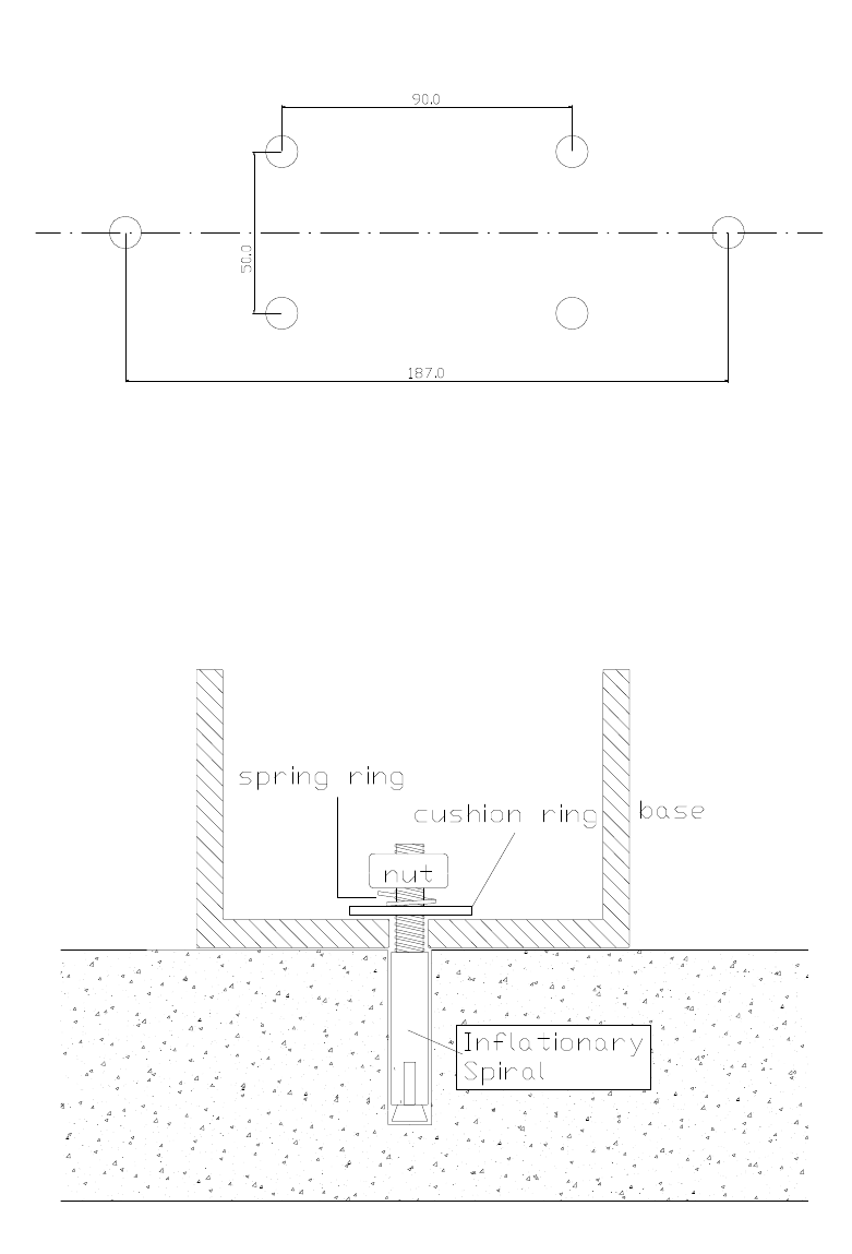
Drill six holes (10mm diameter 40mm deep) to install the base.
Put the Inflationary spirals into the holes
Install the base, allowing the spiral heads to go through the holes of the base
Attach the cushion rings then spring rings and nuts on the spiral heads, screw the
nuts down this will fix the base to the ground.
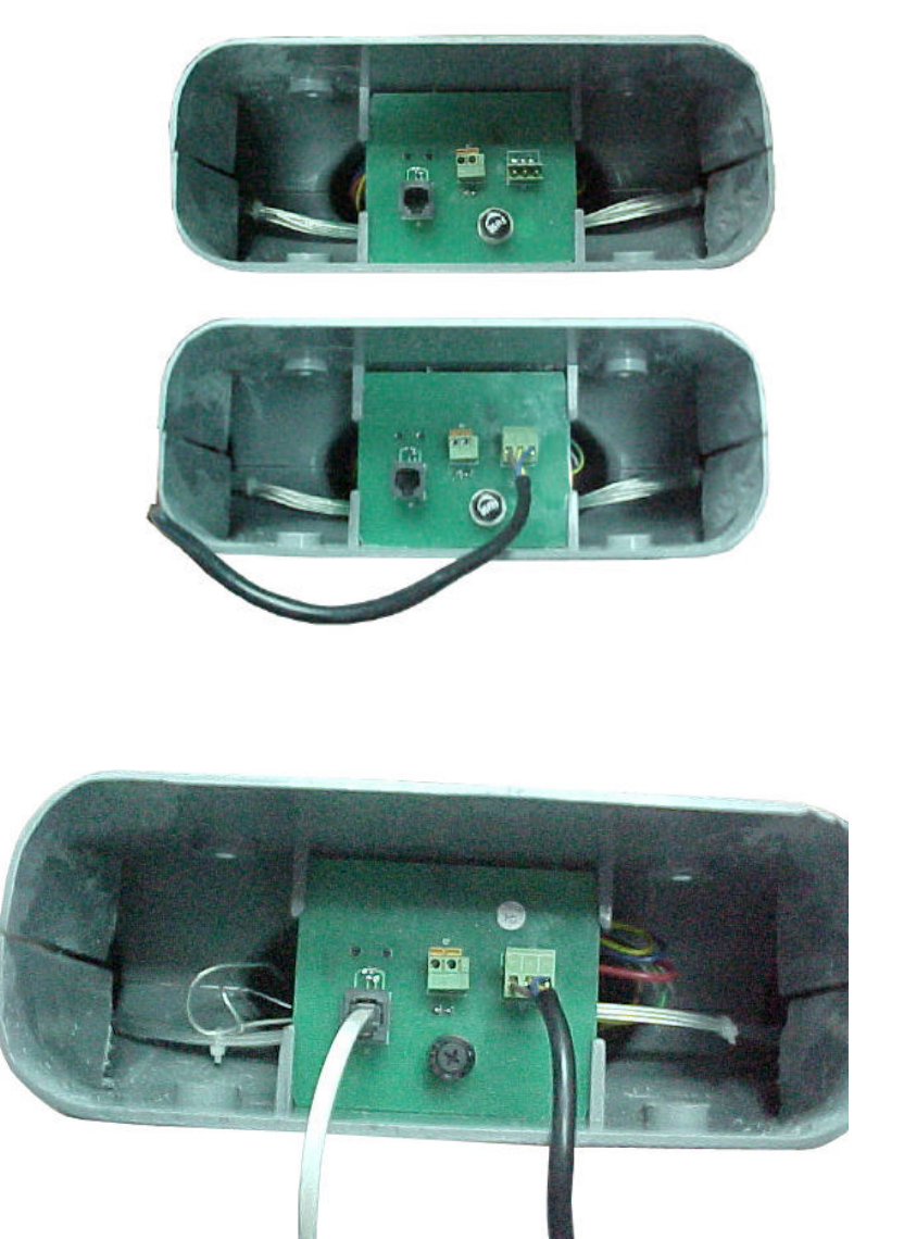
Attach the bottom of the gate to the mount. Plug the power line into the power socket on
the PC Board as the picture shows

58KHz Mono-Guard Transceiver System Quick Start
When using a slave post, connect the interconnection cable into the RJ45
socket on PC Board

58KHz Mono-Guard Transceiver System Quick Start
There are two external alarm outputs. First press down the yellow button, then insert the
external alarm wire into the wire holding hole and release the yellow button, the wire will
be fixed onto the system. Each external alarm output has a contact rating of 1A/220VAC
The system has a switch inside the gate body with an option of 220VAC (European
system) and 110VAC input (American system), and it has been set correctly before out
from the factory.

58KHz Mono-Guard Transceiver System Quick Start
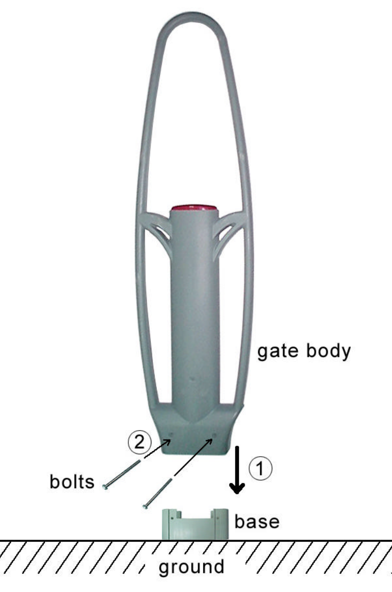
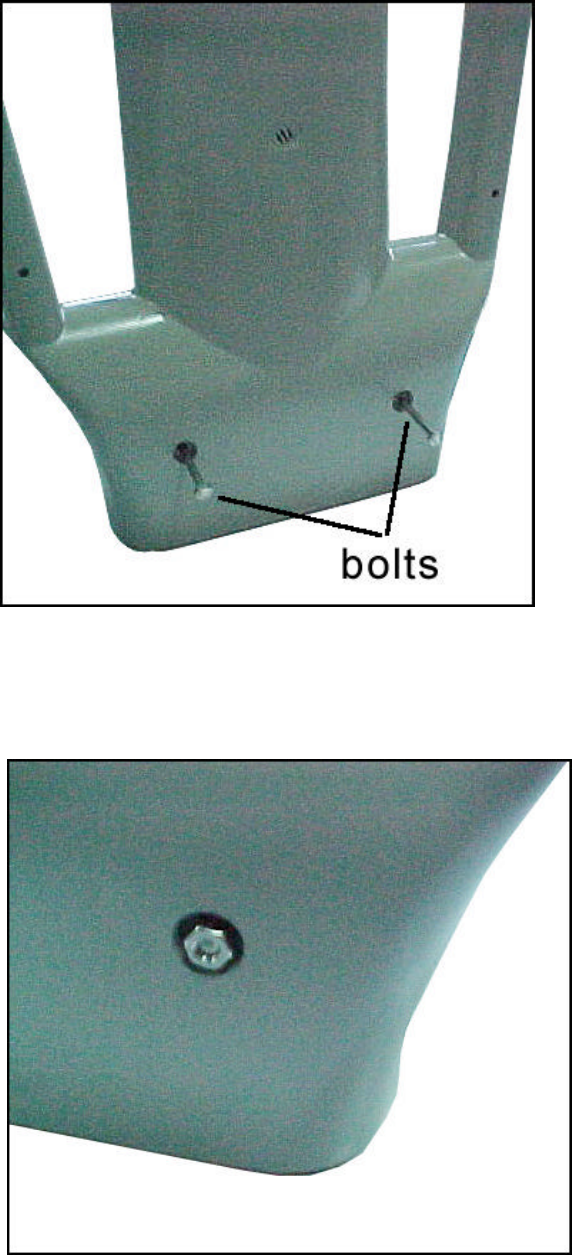
Place the gate body slick into the base track and cover the whole base. Put the two
bolts through the two tunnels at the lower part of the gate body.

58KHz Mono-Guard Transceiver System Quick Start
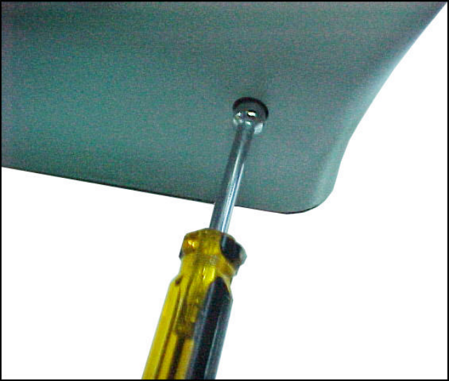
Put the nut onto the bolt head on the other side
Use the tool provided to screw down the nuts

58KHz Mono-Guard Transceiver System Quick Start
Operational Tests
The transceiver system is unique for its plug-on initial self-detection. When the first
time the system is applied with electricity, it takes the system one minute to detect
NONE-TAG environment around. Ensure that during this one minute any tag must be
kept 12 feet away from the detection zone of the system.
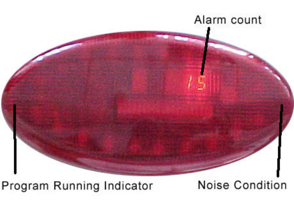
And after one minute, the program running indicator (a yellow led locates at the one
corner of alarm panel) will flash regularly, and the other green led (self-detection
indicator) at another corner of the panel will shut off, which means the system is
ready for detection.
Problems Encountered
If you ensure every step of the installation is correct, all the connections are ok, and the
system still malfunctions, Please call our technical support number (408) 530-8070)
Accessories
A noise shield is available to cover the electronic transformer. This eliminates the
problem of noise from the proximity of Neon Lighting.
58KHz Mono-Guard Transceiver System Quick Start
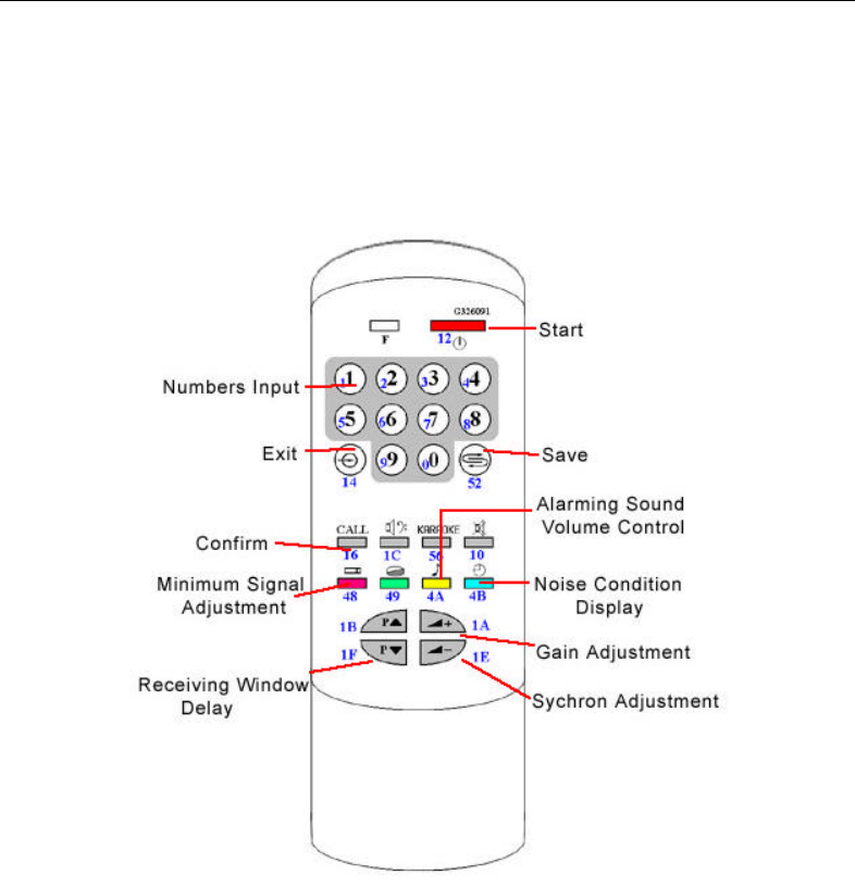
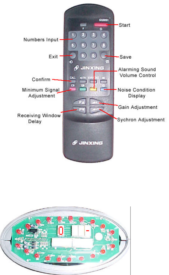
Appendix (IR control keyboard function description)
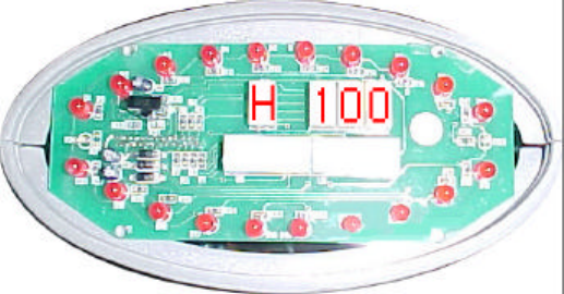
Usually, the most frequently used function is to adjust the Minimum Signal Adjustment
figures, (see entry H). The smaller the figure is, the more sensitive the system is while
the more vulnerable to false alarms. Properly tuning this figure to ensure the system
works at the certain distance at best sensitivity and with minimum false alarms.
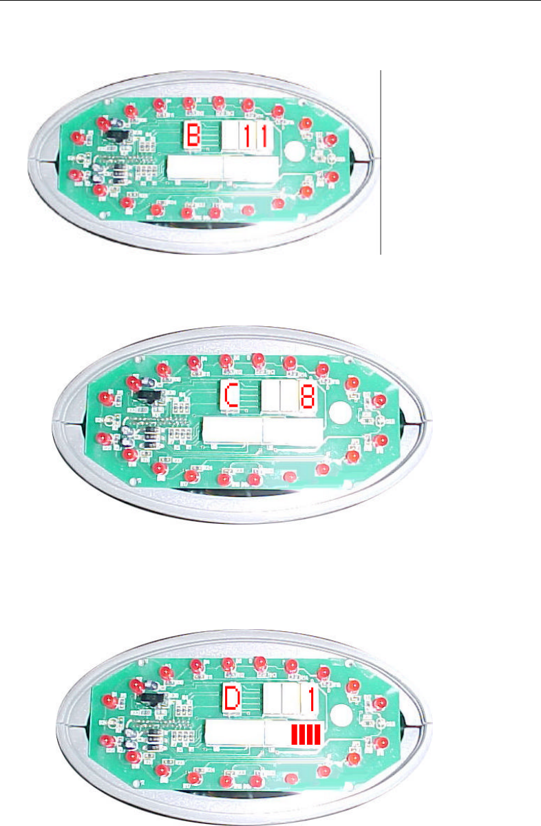
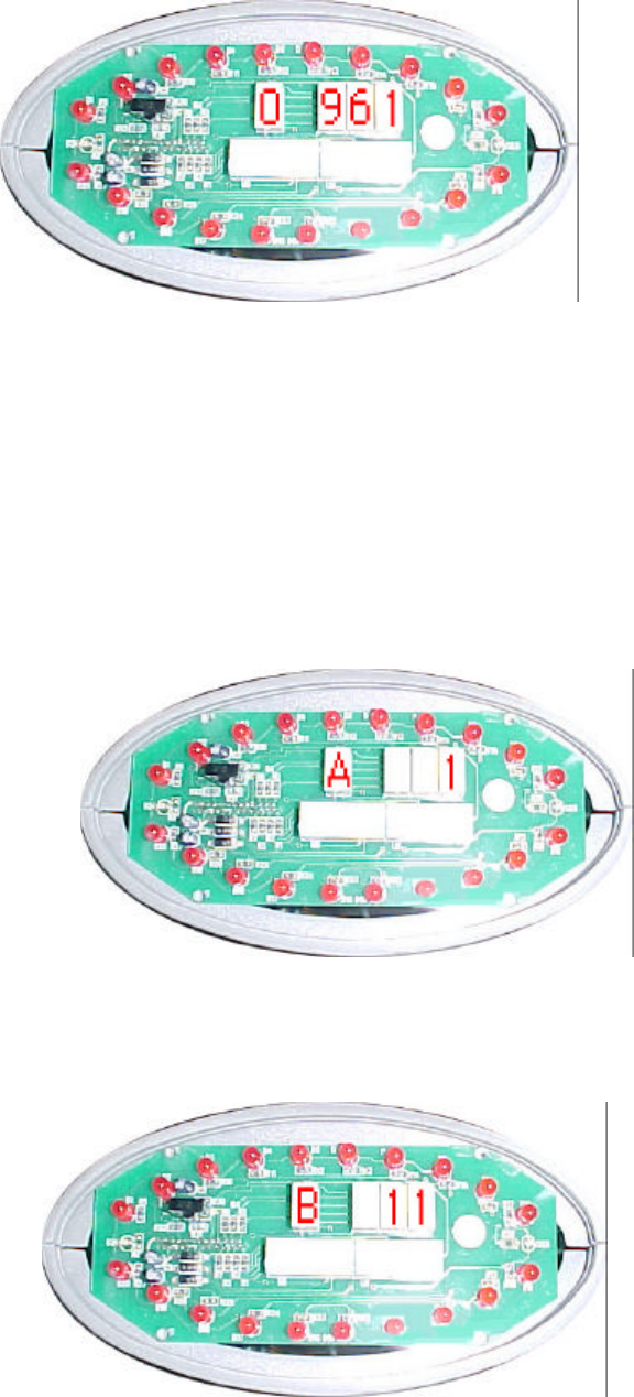
1. Press “start” button to initiate the control when panel shows the following state,
initiation is ready.

58KHz Mono-Guard Transceiver System Quick Start
2. Press password “961”
3. Press “confirm” button
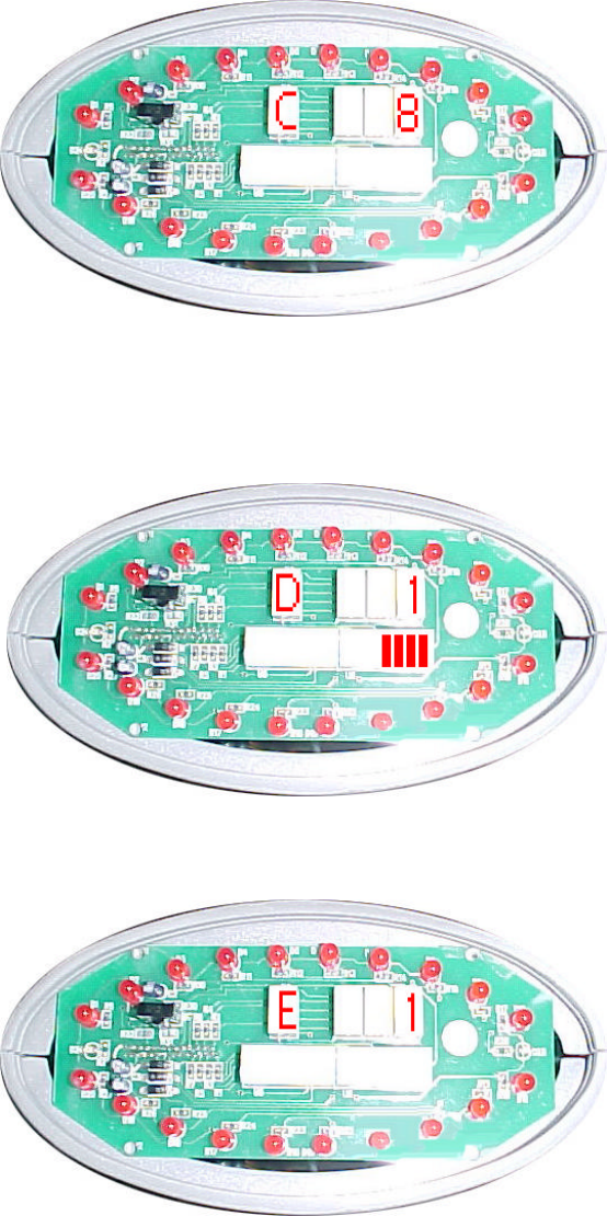
Then enter the control parameters input state. There usually are three steps in
parameters input. The first is select the parameter type, like Gain Adjustment, Sychron
Adjustment or Noise Condition Display; the second step is input the numbers; the third
step is to press “confirm” button.
A. Gain Adjustment
There are two choices here, input 1 to select high gain, 0 to low gain.
B. Sychron Adjustment
58KHz Mono-Guard Transceiver System Quick Start
Here is the time from zero crossing point to the start point of transmitting burst. You
can input 1~254, each stands for 30u seconds.
C. Receiving Window Delay
You can input a number from 1~14, the bigger the number, the later receiving
window will be opened.
D. Noise Condition Display
Here input 1 to show noise condition
Input 2 to show average noise condition
Input 3 to show signal condition
E. Alarming Sound Volume Control
The input range is 1~3, stands for three volume level from small to big.
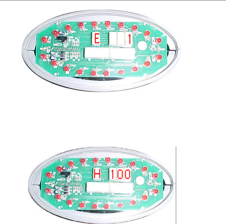
58KHz Mono-Guard Transceiver System Quick Start
H. Minimum Signal Adjustment
Change this figure to admit minimum signal amplitude, in another word any
signal smaller than the level here will be ignored.
Exit button
This button will return control box to last state.
Save button
This button will save all parameters to flash ROM, so when power shut
down the parameters will not be lost.
Note: after press this button, you should press “confirm” button to confirm
saving.
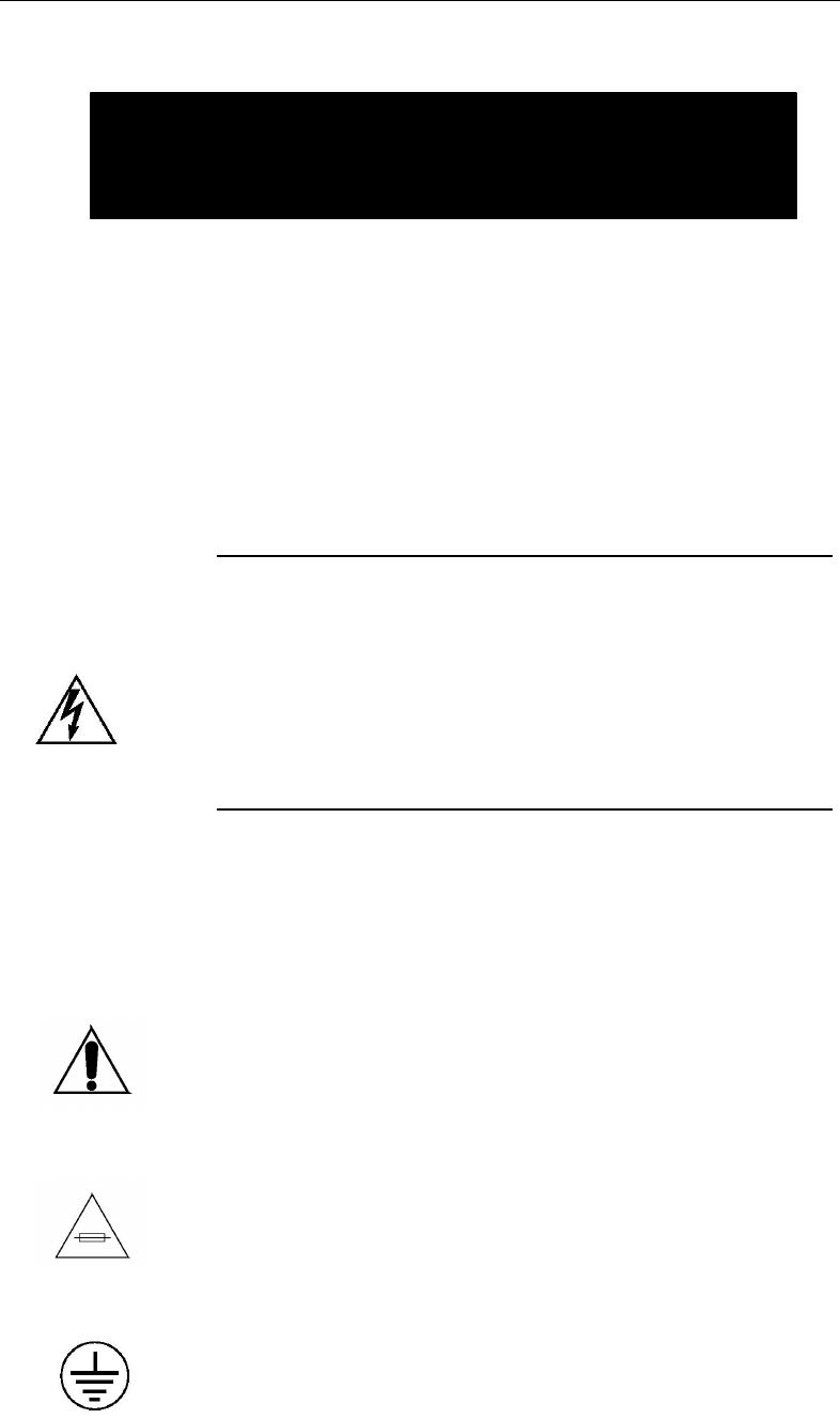
58KHz Mono-Guard Transceiver System Quick Start
Information on the following pages provides important safety
guidelines for both Operator and Service Personnel. Specific warnings
and cautions will be found throughout the manual where they apply,
but may not appear here. Please read and follow the important safety
information, noting especially those instructions related to risk of fire,
electric shock or injury to persons.
WARNING
Any instructions in this manual that require opening the equipment
cover or enclosure are for use by qualified service personnel only. To
reduce the risk of electric shock, do not perform any servicing other
than that contained in the operating instructions unless you are
qualified to do so.
Symbols and Their Meanings
The exclamation point within an equilateral triangle alerts the
user to the presence of important operating and maintenance
(servicing) instructions in the literature accompanying the
equipment.
The fuse symbol indicates that the fuse referenced in the text
must be replaced with one having the ratings indicated.
Important Safeguards and
Regulatory Notices
This symbol represents an internal protective grounding terminal. Such
a terminal must be connected to earth ground prior to making any other
connections to the equipment

58KHz Mono-Guard Transceiver System Quick Start
Danger
Electrical potential is still applied to some internal components even
when the power switch/breaker is in the off position. To prevent electrical
shock when working on this equipment, disconnect the AC line cord from
the AC source before working on any internal components.
A residual voltage may be present immediately after unplugging the
system due to slow discharge of large power supply capacitors. Wait 30
seconds to allow capacitors to discharge before working on the system.
Warnings
Heed all warnings on the unit and in the operating instructions.
Do not use this equipment in or near water.
Disconnect ac power before installing any options.
The attachment plug receptacles in the vicinity of the equipment are all to be
of a grounding type, and the equipment grounding conductors serving these
are to be connected to earth ground at the service equipment.
This equipment is grounded through the grounding conductor of the power
cord. To avoid electrical shock, connect the power cord to the equipment and
plug it into a properly wired receptacle before connecting the equipment
inputs and outputs.
Route power cords and other cables so that they are not likely to be
damaged.
Do not wear hand jewelry or watches when troubleshooting high current
circuits, such as the power supplies.
During installation, do not use the door handles or front panels to lift the
equipment as they may open abruptly and injure you.
To avoid fire hazard, use only components of the specified type, voltage
and current rating as referenced in the appropriate parts list.
Always refer fuse replacement to qualified service personnel.

58KHz Mono-Guard Transceiver System Quick Start
To avoid explosion, do not operate this equipment in an explosive
atmosphere unless it has been specifically certified for such operation.
Have qualified personnel perform safety checks after any completed
service.
Risk of electric shock is present. A grounded circuit conductor
(neutral) is provided with over current protection. Test all components
before touching.
Cautions
To prevent damage to equipment when replacing fuses, locate and
correct the trouble that caused the fuse to blow before applying power.
Verify that all power supply lights are off before removing the power
supply or servicing equipment.
Use only specified replacement parts.
Leave the base of the system clear for air exhaust cooling and to allow
room for cabling. Slots and openings in the system are provided for
ventilation. Do not block them.
To prevent damage to this equipment read the instructions in this
document for proper input voltage range selection.
Circuit boards in this equipment are densely populated with surface
mount and ASIC components. Special tools and techniques are required
to safely and effectively troubleshoot and repair modules that use SMT
or ASIC components. For this reason, service and repair of products
incorporating surface mount technology are supported only on a module
exchange basis. Customers should not attempt to troubleshoot or repair
modules that contain SMT components. It assumes no liability
for damage caused by unauthorized repairs. This applies to both in- and out-
of-warranty products.
Introduction
Congratulations on your purchase of one of the finest EAS systems on
the market. This is the Installation Instructions manual.

58KHz Mono-Guard Transceiver System Quick Start
Receiving Inspection
Inspect all shipping containers for any signs of damage. If any is
found, notify the shipping company. If there is no obvious damage,
continue with the unpacking instructions.
Unpacking Instructions
Place the containers on a flat level surface with enough room to move
the container around as needed. Remove all the remaining manuals and
the Floppy Disk software set. Compare the manuals against the
Inventory sheet and make a note of any discrepancies.
Carefully remove the contents of container and place on a flat level
surface. Compare the contents with the Part List to ensure that there no
missing items. Make a note of any discrepancies.
Equipment Inspection
Inspect all equipment for damage. Items to specifically check, and
damage to look for, are listed below:
All connectors for bent or broken pins
Cables for crimped or broken wires
Plastic housing for any obvious signs of damage
If any damage is found, contact Customer Service at the telephone number in
the front of this manual. If any item is damaged, DO NOT make any power
or signal connections to the unit unless otherwise advised to do so by
Customer Service.
If there are any discrepancies between the Manual Set Inventory sheet and the
manuals received, or between the Packing List and items received, contact
Customer Service at the telephone number at the front of this manual. If there
are no discrepancies and either no damage, or GVG-advised correction action
is made, continue with this manual.
Facility Checklist
The following checklist is a synopsis of information found in the
appropriate Installation Planning Guide. The Planning Guide should be
referred to for detailed site preparation information. Ensure that there are
sufficient AC power outlets of the required 3-prong grounded type and amp
rating for the intended equipment.
Overview
System Description
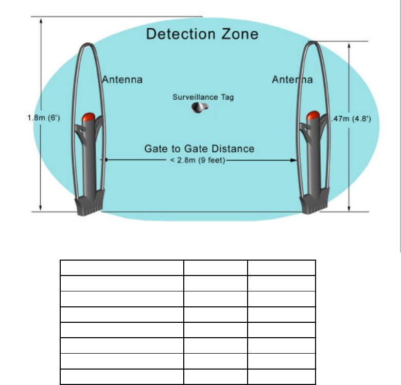
The Multi-Guard system is a dual pedestal Electronic Article Surveillance system that
works with any 58KHz accusto-magnetic tag. This system is plug and play, which
eliminates the need for expensive technicians during installation.
The Multi-Guard system is fully digital, software driven, and has the latest DSP technology
that constantly checks the environment: This eliminates false alarms that you get from
using other systems. The Multi-Guard system can operate at a higher level of sensitivity,
resulting in an excellent detection rate up to 2.8 meters (9 feet) between two pedestals.
Technical Data Europe United States
Height 1470mm 58"
Width 440mm 15.5"
Depth 100mm 3.5"
Weight 10Kg 22lbs
Power 200-220vac 110vac
Operating Frequency 58kHz 58kHz
Maximum Tag Detection 2.8 meters 9 feet
Features
Digital Signal Processing
The Multi-Guard system applies the latest and most technically advanced DSP
technologies to address antitheft problems. It minimizes false alarms while maintaining
considerable detection range.
Self-Tuning Electronics
Other manufacturers need professional technicians to tune their systems to ensure proper
functioning. But once the environment condition changes, the systems best working
position changes and requires tuning again. The Multi-Guard system, benefiting from its
fully digital electronics, constantly detects the environment & automatically adapts to any
changes. It will always operate at its optimum performance from the beginning.
Software Driven
The Multi-Guard is fully digital software driven system, which allows unprecedented
flexibility especially in later versions.
Applications
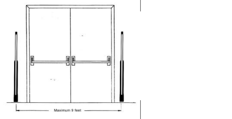
This type of installation consists of one
transmitter and one receiver pedestal.
The Multi-
Guard system uses an
interconnecti
on cable from the
transmitter to the receiver. The gates
are mounted on both sides of the
opening and cover a maximum
distance of 9 feet (when using our
Supersensor or Super Pencil tag)
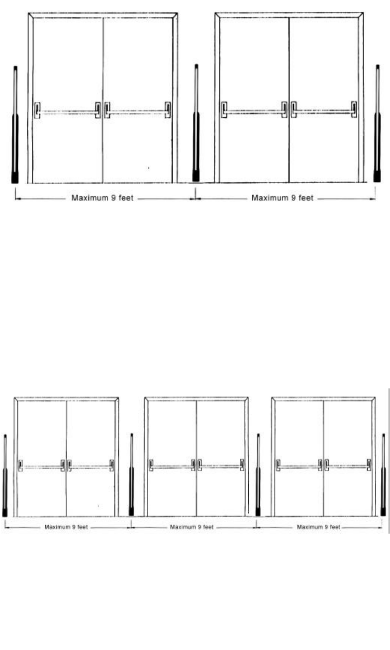
This type of installation consists of one receiver and two transmit
ters. Installing the
receiver in middle and the transmitters at the ends. Each transmitter post will be
connected to the receiver post. The Multi-
Guard system uses an interconnection
cable from the transmitter to the receiver. The gates are mounted on both
sides of the
opening and cover a maximum distance of 18 feet (when using our Supersensor or
Super Pencil tag)
Then the wider the opening, the more systems are needed. This type of installation
consists of two-transmitters and two-receiver pedestal with i
nterconnection from the
transmitter to the receiver. The gates are mounted on both sides of the opening and
cover a maximum distance of 27 feet. (When using our Supersensor or Super Pencil
tag)
Installation Procedures
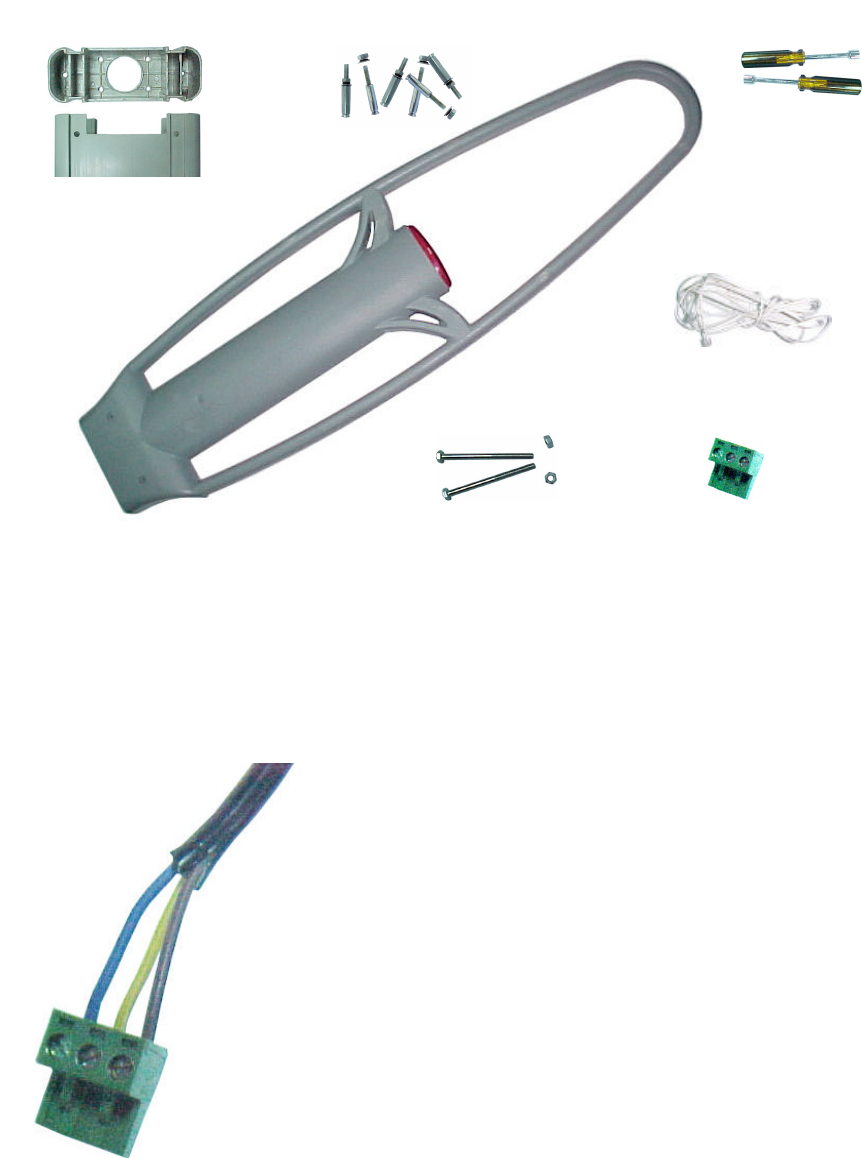
Parts List
Installation Procedures
Pipe the power line to where the post will be mounted
Mount the plug on the power line
Drill six holes (10mm diameter 40mm deep) to install the base.
Base (2) Inflationary spiral (12 sets)
Interconnection Cable (1)
Bolts (2 sets)
Power
line plug
(2)
Multi-Guard (1 Pair)
Transmitter & Receiver
Put the plug to face towards you with
the side where there are metal
screws. Connect the N line to left
terminal, the L line
to right terminal,
and the ground line to middle
terminal.
Tools (2 sets)
Put the Inflationary spirals into the holes
Install the base, allowing the spiral heads to go through the holes of the base
Attach the cushion rings then spring rings and nuts on the spiral heads, screw the nuts
down this will fix the base to the ground.
Lift the gate bottom mount the power line plug in to the power socket on the bottom of the
PC Board as the picture shows
Connect the interconnection cable in to the RJ45 socket on PC Board as the picture
shows, (both transmitter and receiver)
Put the gate body slick into the base track and cover the whole base.
Put the two bolts through the two tunnels at lower part of the gate body
Put the nut onto the bolt head on the other side
Use the tool to screw down the nuts
Operational Tests
Turn the power on; the system will begin its environment check and start running the
software program. Wait for several seconds and you will see the LED panel stop flashing.
When the system is in the idle position the number 0 on the alarm count generator will be
illuminated. On the left part of the panel, a program running indicator (Yellow Light) will
flash regularly. On the right corner, a noise condition indicator light (green) will flash with a
frequency associated with the noise level. The more frequently it flashes, the worse the
noise is. At this stage, the system is ready for tag detection.
Encountering Problems
If you ensure every step of the installation is correct, all the connections are ok, and the
system still malfunctions, Please call our technical support number (408) 530-8070)
Appendix (IR control keyboard function description)
Press, “start” button to initiate the control
When panel shows the following state, initiation is ready
Enter password “961”
Press “confirm” button
Then enter the control parameters input state. There are three steps in the parameters
input. The first is select the parameter type, like Gain Adjustment, Sychron Adjustment or
Noise Condition Display; the second step is input the numbers; the third step is to press
“confirm” button.
Gain Adjustment
There are two choices here, input 1 to select high gain, 0 to low gain.
Synchrony Adjustment
This is the time from zero crossing point to the start point of the transmitting burst. You can
input 1~254, each stands for 30 seconds.
Receiving Window Delay
You can input a number from 1~14, the bigger the number, the later receiving window will
be opened.
Noise Condition Display
Here input 1 to show noise condition
Input 2 to show average noise condition
Input 3 to show signal condition
Alarming Sound Volume Control
The input range is 1~3, stands for three volume level from small to big.
Minimum Signal Adjustment
Change this figure to admit minimum signal amplitude, in others words any signal smaller
than the level here will be ignored.
Exit button
This button will return control box to last state.
Save button
This button will save all parameters to flash ROM, so when power shut down the
parameters will not be lost.
Note: After you have pressed this button, you should press the, “confirm” button to confirm
you have saved the information.