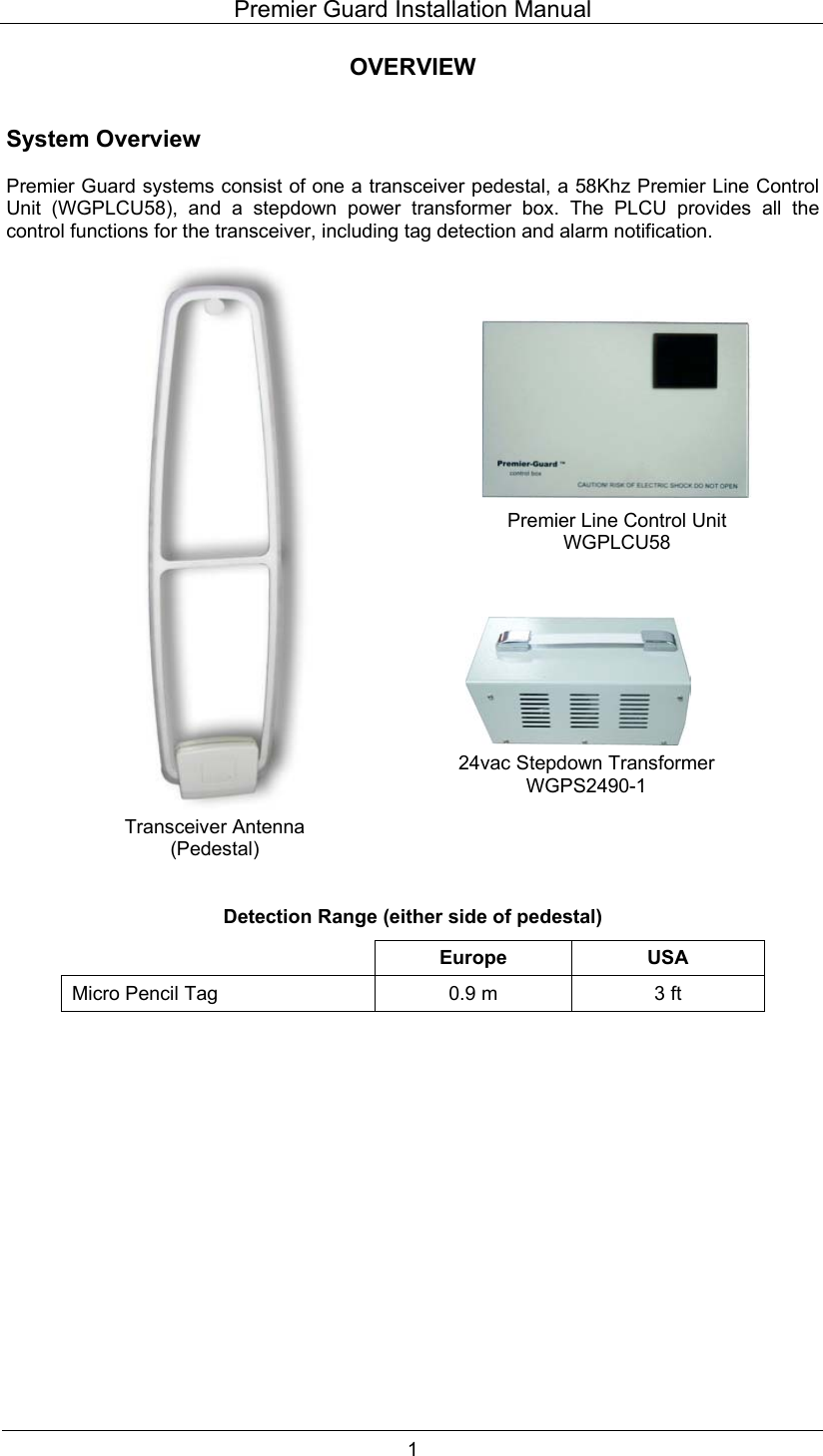
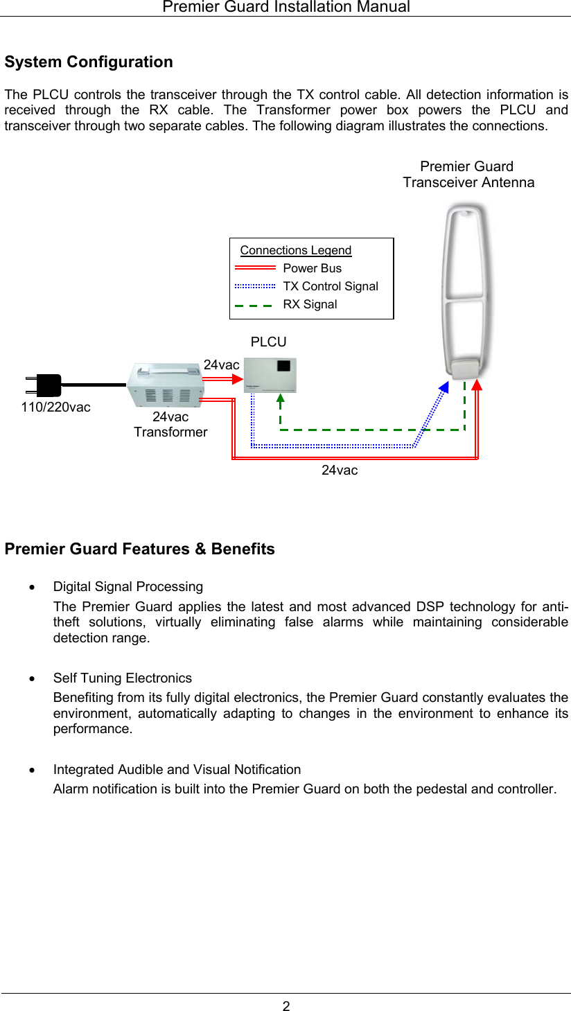
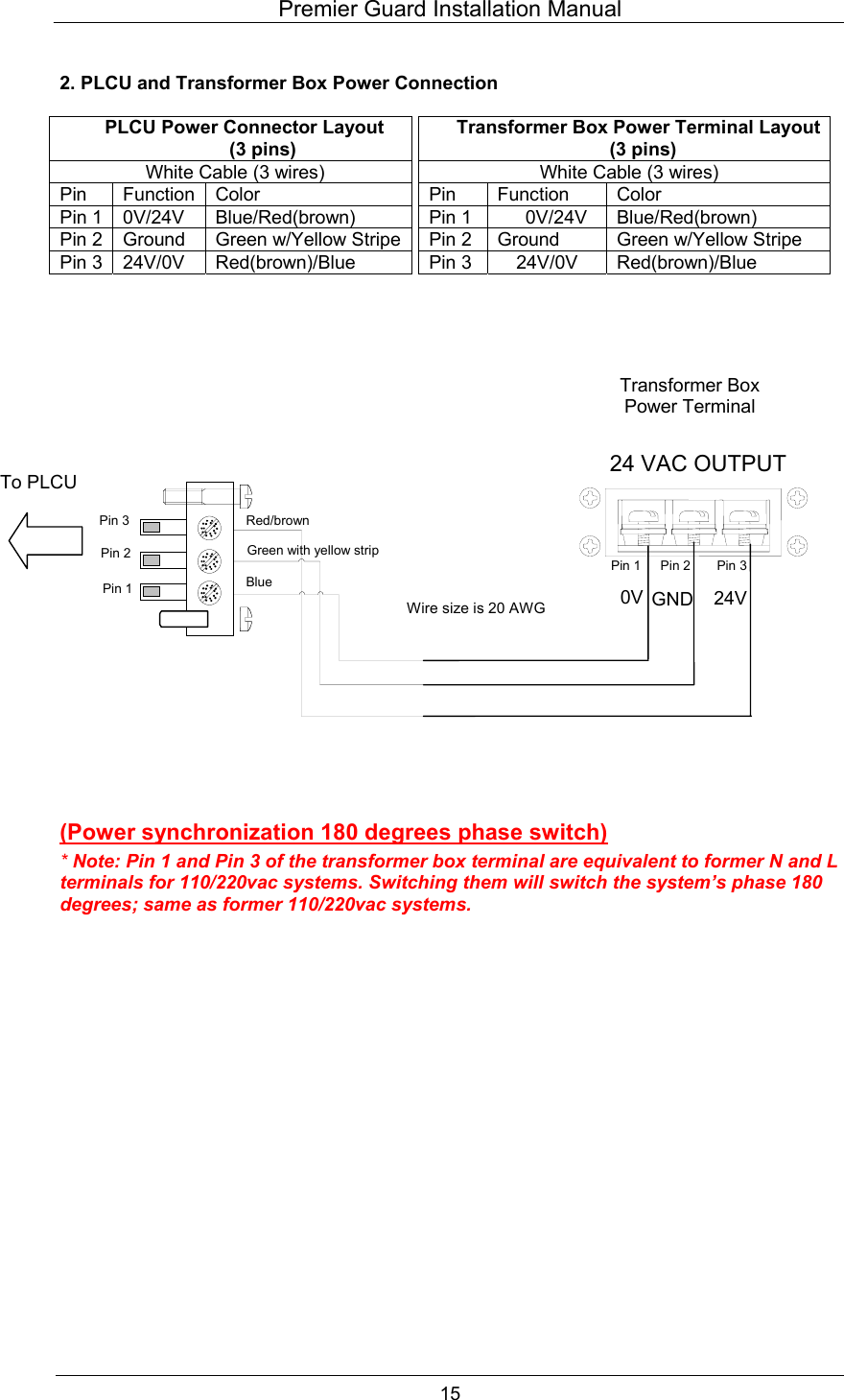
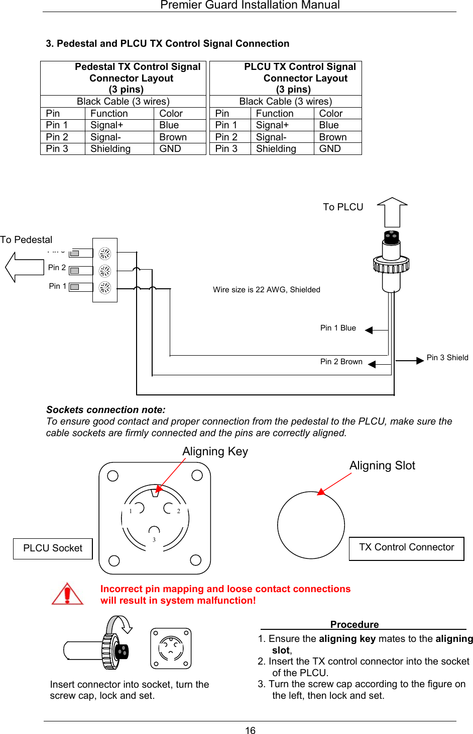
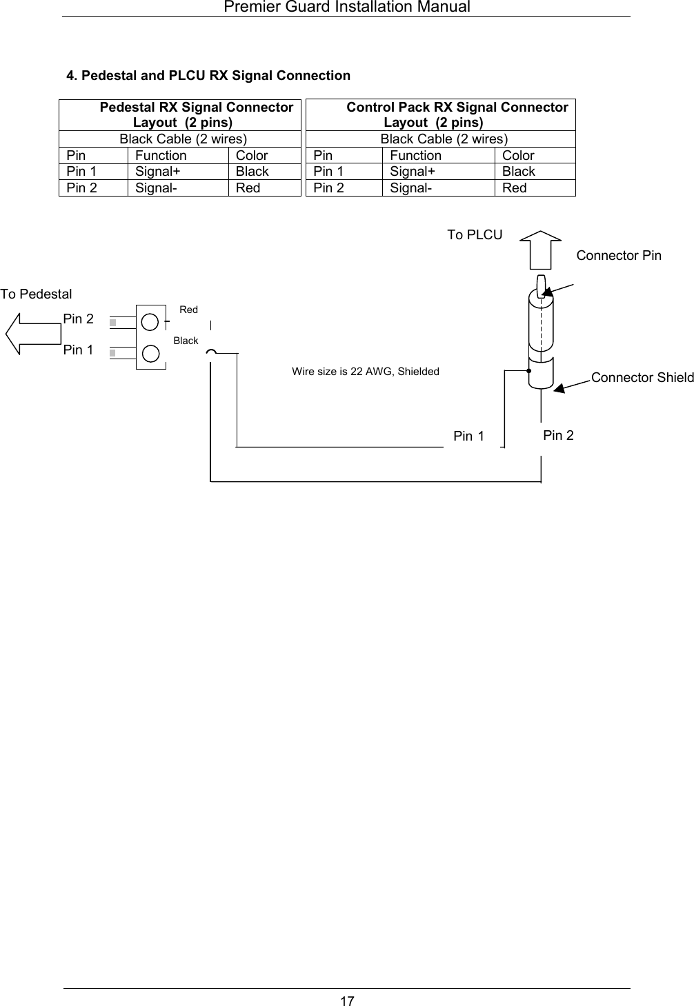
WG security WGPPTR58 EAS System User Manual Manual Premier Guard 011306A
WG Security Products, Inc EAS System Manual Premier Guard 011306A
UserManual.wiki
>
WG security
>
WGPPTR58 User Manual
>
Manual for Premier Guard
Contents
1.
Manual for Premier Guard
2.
User Manual for Premier Pro
Manual for Premier Guard
Navigation menu
Upload a User Manual
Namespaces
Wiki Guide
HTML
PDF
Info
Views
User Manual
Discussion / Help
Navigation
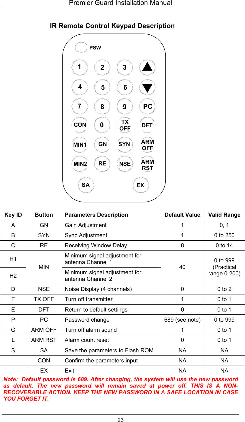
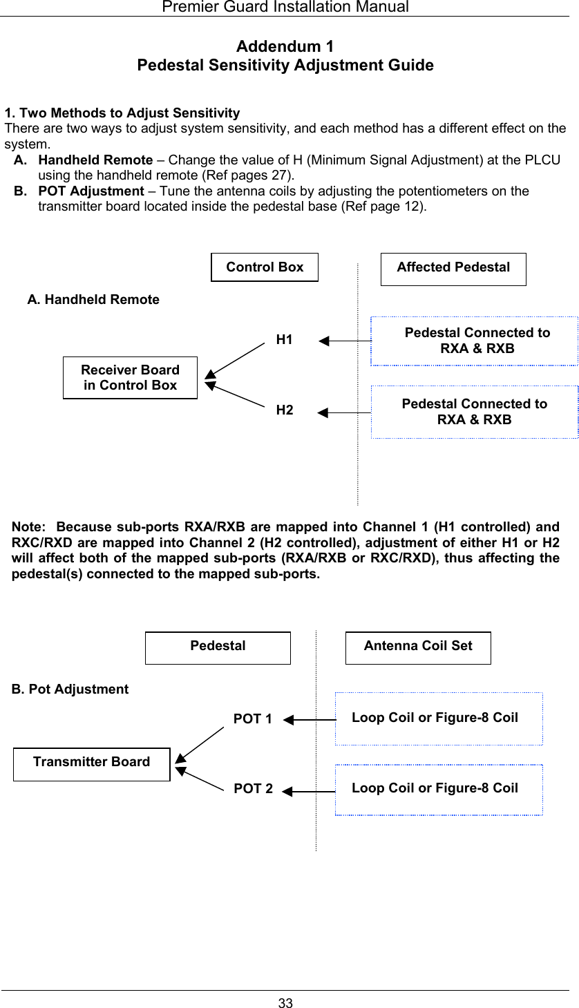
![Premier Guard Installation Manual 25 Remote Control Programming Without receiving remote control signals, the panel displays the alarm count, indicating the number of times the system has alarmed. See Figure 1. Figure 1. Alarm Count Press [PSW] button to open the remote control, then enter the password. The default password, if not previously changed, is 689. Figure 2. Display after [PSW] is Pressed Input Password 689 and press [CON] to confirm/accept the password. 01 0 0 6 98](https://usermanual.wiki/WG-security/WGPPTR58.Manual-for-Premier-Guard/User-Guide-925284-Page-29.png)
![Premier Guard Installation Manual 26 Note: Inputting the wrong password will cause an error message to be displayed as per the following picture. After three successive times of inputting an incorrect password, the remote will be disabled. You will need to turn system power off/on and input the password again. When the correct password is verified, the panel will display the following and is now ready for receiving configuration inputs. There are three basic steps to inputting a programming parameter: • Press function button. • Input parameter number. • Press [CON] to accept the parameter. After parameter confirmation, the panel will display the tag window signal. If there is no tag in the detection zone, the value reflects the noise level in the receiving window without a tag. The upper value reflects the signal level in the tag window from antenna channel 1. The lower value reflects the signal level in the tag window from antenna channel 2. (See NSE noise display entry; it’s the same value with D1) CH 1CH 2 0 E rr - 94- 13](https://usermanual.wiki/WG-security/WGPPTR58.Manual-for-Premier-Guard/User-Guide-925284-Page-30.png)
![Premier Guard Installation Manual 27 Key ID A: Gain Adjustment (Range: 0-1) • Press [GN] – panel displays as per Figure 3. • Input parameter number. • Press [CON] to accept the parameter. Figure 3. Key ID B: Sync Adjustment (Range: 0-250; increment: 1) This sets the time from zero crossing point to the start point of transmitting burst. It is important to eliminate crosstalk between different systems. Setting the default value to b-1 will in most cases not interfere with other AM products. • Press [SYN] – panel displays as per Figure 4.1. • Input parameter number. • Press [CON] to view the nose conditions. Display will be as per Figure 4.2. Figure 4.1 Under this entry, you can also see the different noise condition (from the light segment display and number indicator) at a different phase when the adjustment is applied. It will help you select a relatively “clean” phase environment for the system. Figure 4.2 CH 1CH 2 A 1 b 1 13- 74](https://usermanual.wiki/WG-security/WGPPTR58.Manual-for-Premier-Guard/User-Guide-925284-Page-31.png)
![Premier Guard Installation Manual 28 Key ID C: Receiving Window Delay (Range: 0-14; increment: 1) You can input a number from 1-14. The larger the number, the later the receiving window will be opened. • Press [RE] – panel displays as per Figure 5. • Input the parameter number. • Press [CON] to accept the parameter. Figure 5. Key ID D: Noise Condition Display (Range: 0-4) There are 6 noise level channels displaying different noise types from the two antenna channels. The noise value range is 0 to 999. Usually any noise larger than 100 will be considered as heavy noise. See details in the next table. Note: If the noise condition display is open, the alarm will be deactivated unless you input 0 to shut down the display. • Press [NSE] – panel displays as per Figure 6.1. • Input the parameter number. • Press [CON] to accept the parameter – panel displays as per Figure 6.2. Figure 6.1 Figure 6.2 CH 1CH 2 C 4 d 4 94- 13](https://usermanual.wiki/WG-security/WGPPTR58.Manual-for-Premier-Guard/User-Guide-925284-Page-32.png)
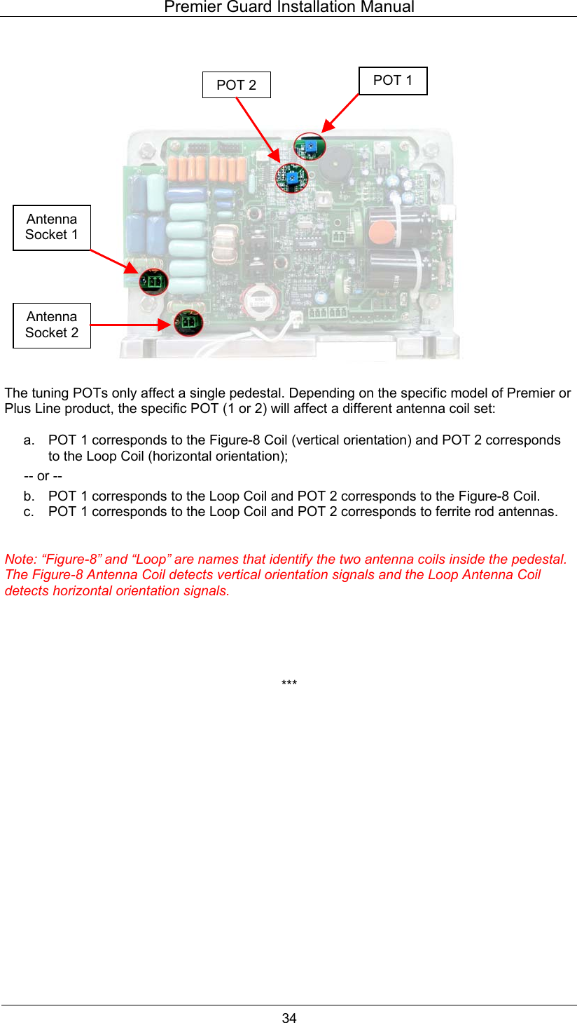
![Premier Guard Installation Manual 29 Noise Condition Display Configuration Table Value Function Description Detection Purpose 0 Shut down tag or noise window display. D1 Tag window display for channel one. Detect tag entering vertically. D2 Tag window display for channel two. Detect tag entering horizontally. D3 Average noise window display for channel one. D4 Average noise window display for channel two. Monitor average noise. Note: The average noise level (D3 & D4) is also weighted by the Minimum Signal Adjustment value. Therefore, if MIN (H value) is increased to be larger than the average noise level, D3 or D4 will only show the H value instead of the average noise value. Key ID H: Minimum signal Adjustment (Suggested increment: 20; practical range: 0-200) Decreasing this number will increase system sensitivity but also at the risk of false alarming. Vice versa, increasing the value will lower system sensitivity to avoid false alarms caused by uncontrollable environment noise. There is also an auxiliary POT for RX signal pre-process sensitivity adjustment (see page 18 and Addendum 1). There are two antenna channels. Channel 1 is related to vertical orientation and Channel 2 is related to horizontal orientation. H1 (MIN1) sets the minimum signal of Channel 1, and H2 (MIN2) sets the minimum signal of Channel 2. • Press [MIN] – panel displays as per Figure 7. • Input the parameter number. • Press [CON] to accept the parameter. Figure 7.1. Antenna Channel 1 Figure 7.2. Antenna Channel 2 H 1 04 H 2 04Note: See Addendum 1 for additional tuning instructions.](https://usermanual.wiki/WG-security/WGPPTR58.Manual-for-Premier-Guard/User-Guide-925284-Page-33.png)
![Premier Guard Installation Manual 30 After confirmation of H1 or H2 values, the panel will display the average noise level weighted by the minimum signal adjustment for both antenna channels as follows. (See NSE noise display entry. It’s the same value with D3, D4) D3 reflects the average noise level weighted by H1 (MIN1) in antenna channel 1. D4 reflects the average noise value weighted by H2 (MIN2) in antenna channel 2. Key ID F: TX Off (Default value: 1; valid range: 0-1) Value Action 0 Turn off Tx 1 Turn on Tx • Press [TX OFF] • Input the parameter number. • Press [CON] to accept the parameter. Input 0 will turn down the transmitting burst via software control. If system power is reapplied, the system will return to default state of 1. Key ID G: Alarm Sound Off (Default value: 1; valid range: 0-1) Value Action 0 Turn off alarm sound. 1 Turn on alarm sound. • Press [ARM OFF] • Input the parameter number. • Press [CON] to accept the parameter. Input 0 will turn down the alarm sound via software control. If system power is reapplied, the system will return to default state of 1. Key ID L: Alarm Count Reset (Default value: 0; valid range: 0-1) Value Action 0 Initial state. 1 Reset alarm count. • Press [ARM OFF] • Input the parameter number. • Press [CON] to accept the parameter. Input 1 will reset the alarm count to 0. CH 1CH 2 94- 13](https://usermanual.wiki/WG-security/WGPPTR58.Manual-for-Premier-Guard/User-Guide-925284-Page-34.png)
![Premier Guard Installation Manual 31 Key ID E: Load Default Settings (Default value: 0; valid range: 0-1) Value Action 0 Initial state. 1 Load default settings. Input 1 will load default settings. See Default Parameters Table. Key ID P: Password Change (Default value: 689; valid range: 0-999) You can input customer-defined passwords with this entry. Press [CON] button after inputting to activate the new password. Note: Please SAFEGUARD the new password if you have changed from the default. Once the new password is activated, the system will no longer recognize the 689 default password. Key ID EX: Exit Press [EX] to return to the alarm counter display status. Key ID SA: Save This button will save all current parameters to flash ROM and are saved, even after power shutdown. When the system is rebooted, it will load all previously saved parameters from flash ROM. • Press [SA] – panel displays as per Figure 8. • Input 1 • Press [CON] to accept the current parameters. Figure 8. 5 1](https://usermanual.wiki/WG-security/WGPPTR58.Manual-for-Premier-Guard/User-Guide-925284-Page-35.png)